
APA4320 - Autoradio CLARION - Kostenlose Bedienungsanleitung
Finden Sie kostenlos die Bedienungsanleitung des Geräts APA4320 CLARION als PDF.


| Produkttyp | Autoradio |
| Marke | Clarion |
| Modell | APA4320 |
| Einbaugröße | 1 DIN (180 x 50 mm) |
| Gewicht | ca. 1 kg (ohne Verpackung) |
| Betriebsspannung | 12 V DC |
| Stromaufnahme | max. 10 A |
| Ausgangsleistung | 4 x 50 W (max.) |
| Frequenzbereich UKW | 87,5 – 108 MHz |
| Frequenzbereich MW | 531 – 1602 kHz |
| CD-Player | Ja |
| Unterstützte Formate | CD, CD-R, CD-RW |
| AUX-Eingang | 3,5 mm Klinke |
| Senderspeicher | 30 FM, 12 MW |
| Display | LCD mit Hintergrundbeleuchtung |
| Fernbedienung | optional (nicht im Lieferumfang) |
| Sicherung | 15 A (im Gerät) |
| Reinigung | Mit einem weichen, trockenen Tuch |
| Reparaturfähigkeit | Nur von autorisiertem Fachpersonal |
| Lieferumfang | Autoradio, Einbauset, Bedienungsanleitung |
Häufig gestellte Fragen - APA4320 CLARION
Benutzerfragen zu APA4320 CLARION
0 Frage zu diesem Gerät. Beantworten Sie die, die Sie kennen, oder stellen Sie Ihre eigene.
Eine neue Frage zu diesem Gerät stellen
Laden Sie die Anleitung für Ihr Autoradio kostenlos im PDF-Format! Finden Sie Ihr Handbuch APA4320 - CLARION und nehmen Sie Ihr elektronisches Gerät wieder in die Hand. Auf dieser Seite sind alle Dokumente veröffentlicht, die für die Verwendung Ihres Geräts notwendig sind. APA4320 von der Marke CLARION.
BEDIENUNGSANLEITUNG APA4320 CLARION
clarion
APA4320
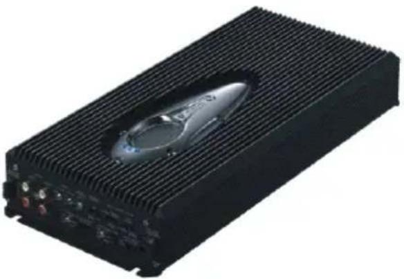
160W x 4 Channel Power Amplifier OPERATION AND INSTALLATION MANUAL
natural_image
Exterior view of a black electronic device with a central lens (no visible text or symbols)-1. INTRODUCTION
1) Strong Power Supply
The APA4320 uses a high performance MOS-FET and a strong power supply circuit with a DC-DC converter, high capacity low impedance capacitors, and a gapped E core choke coil. This makes for an extremely stable supply for power despite the harsh power fluctuations and environmental changes particular to cars and clear sound.
2) Designed for high sound quality
A low-noise operation amplifier and layered film capacitors reproduce the energetic low bass and clear, undistorted sound provided by such digital sources as Compact Discs and DVD.
3) Low distortion and wide output range.
The APA4320 offers stable playback with high output simultaneously from the 4 channels and low distortion even beyond the range of frequencies audible to the human ear.
4) Output Mode Selector
An output mode selector switch provides the following high output(rated):
• 4-channel mode…80W x 4
• 3-channel mode…80W x 2 + 230W x 1
• 2-channel mode…230W x 2
5) High pass/Low pass variable electronic crossovers
The APA4320 incorporates a selectable High Pass or Low Pass electronic crossover for all 4 channels. In both cases, the crossover point it fully adjustable between 55 Hz to 550 Hz and features a -12dB per octave roll off. The frequency range changeover switch enabled it to switch to 550 Hz to 5,500 Hz high region range (INPUT CH3/4 only) and effective for tweeter connection.
6) Bass extender circuitry(INPUT CH1/2 only) Adding "boost" to low frequency sound information make it able to perform frequency compensation according to the system, produces well-balanced output.
7) Protection circuit.
A protection circuit is used to constantly protect against damage to the amplifier from loads, short-circuits, overcurrents, overheating, etc.
2
AMPLIFIER CONTROLS AND POWER INDICATOR CONNECTIONS
Front Panel Layout
Gain Control
Adjustment of an amplifier Input level can be performed.
- To protect the speakers the gain control knobs are set to "MIN" position upon shipment. Once the audio system is installed and connected, turn the knobs clockwise to increase the output level.
- The output level differs according to the combination of main unit, amplifier and speakers.
- Be particularly careful not to set the gain control knobs too high when using speakers with a low input impedance.
- Gain control knob CH1/2 adjust the output level for the signals input to the INPUT CH1/2.
- Gain control knob CH3/4 adjust the output level for the signals input to the INPUT CH3/4.
INPUT Mode Selector Switch
· 2CH BASS : Input channel are CH1, CH2.
CH1, CH2 input signal are outputted from CH1, CH2 output terminal and CH3, CH4 output terminal.
Bass Extender work for CH1/2, CH3/4 all output channel at once.
· 2CH : Input channel are CH1, CH2.
CH1, CH2 input signal are outputted from CH1, CH2 output terminal and CH3, CH4 output terminal.
Bass Extender work only for OUTPUT CH1/2 (No effect for OUTPUT CH3/4).
· 4CH : Input Channel are CH1, CH2, and CH3, CH4.
CH1, CH2 input signal are outputted from CH1, CH2 output terminal.
CH3, CH4 input signal are outputted from CH3, CH4 Output terminal.
Bass Extender work only for OUTPUT CH1/2 (No effect for OUTPUT CH3/4)
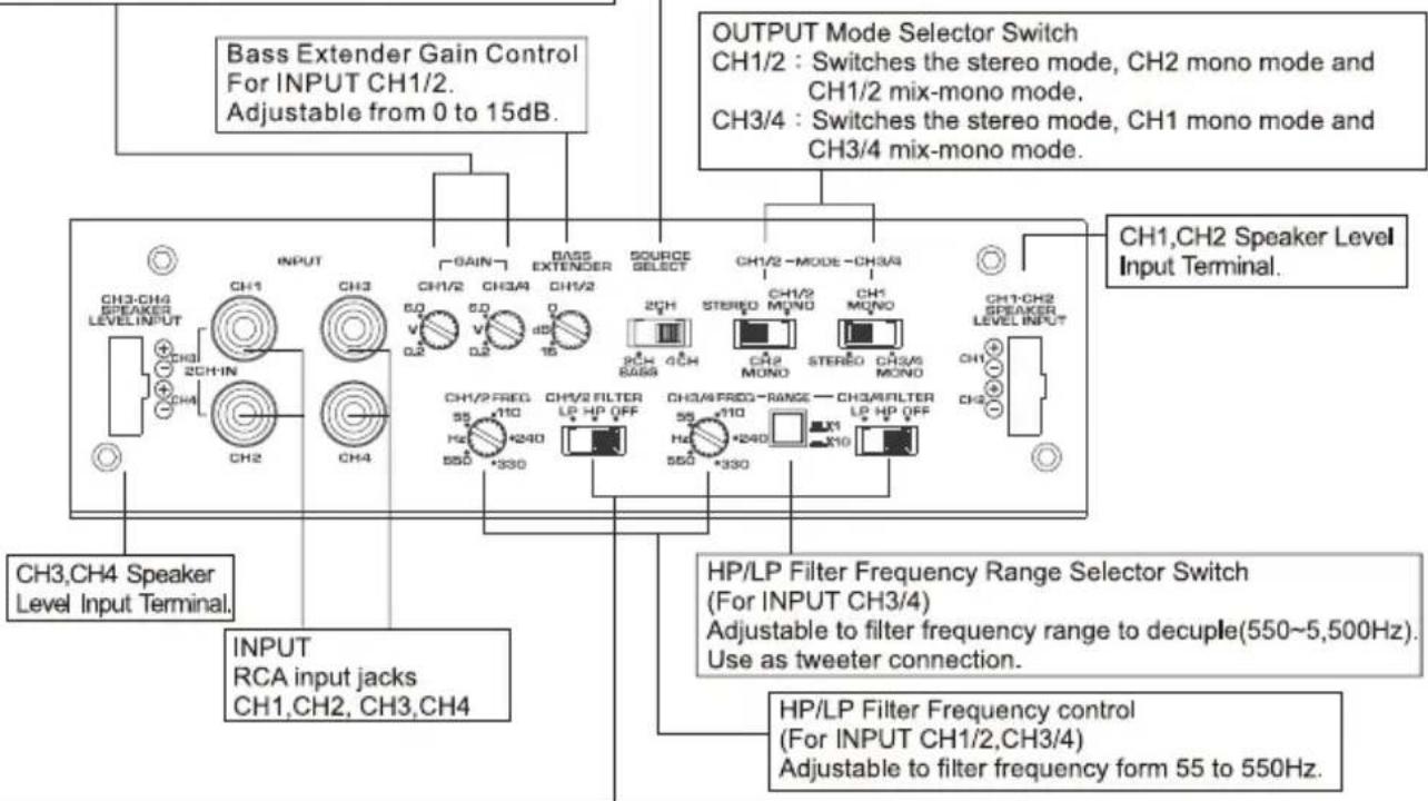
HP/LP Filter Selector Switch
For CH1/2,CH3/4
OFF : Full frequency audio signals are passed through the amplifier.
HP : Only the audio signals which cut low frequency are passed through the amplifier. (Adjust HP/LP Filter Frequency control form 55 to 550Hz).
LP : Only the audio signals which cut high frequency are passed through the amplifier. (Adjust HP/LP Filter Frequency control form 55 to 550Hz).
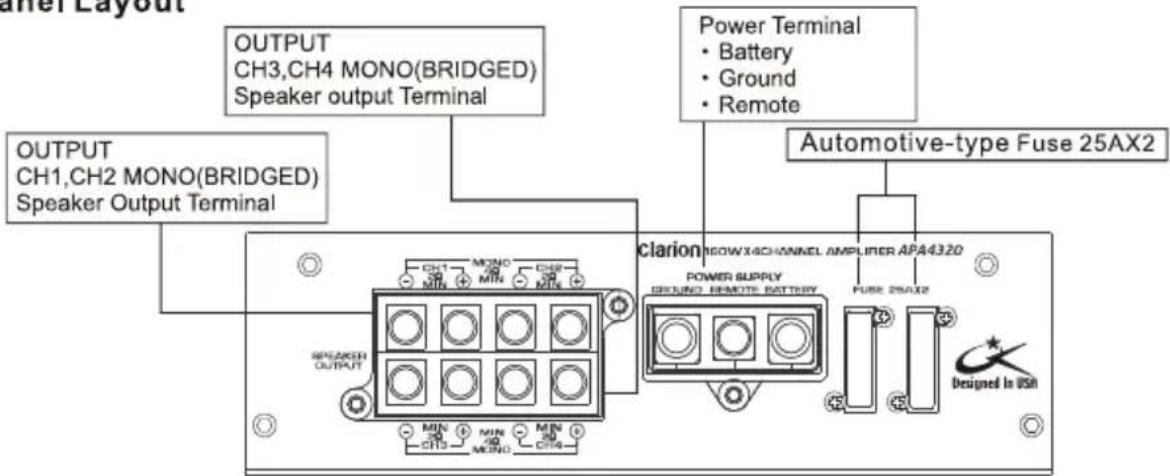
Rear Panel Layout
3. NOTE
1) Keep in mind that it will become the cause of battery stage fright if engine is cut and you use it for a long time.
2) When as follows, a protection circuit operates. Please use correctly after removing a cause.
- The leather film of a speaker code was torn and the code contacted the body.
• The speaker terminal short-circuited.
- The main part of amplifier carried out unusual generation of heat.
- When a large output which the main part of a speaker damages is performed continuously. Sound stops in this case.
* When sound does not come out after removing the above-mentioned cause, please consult with Clarion dealer.
4. INSTALLATION
Electrical Connections
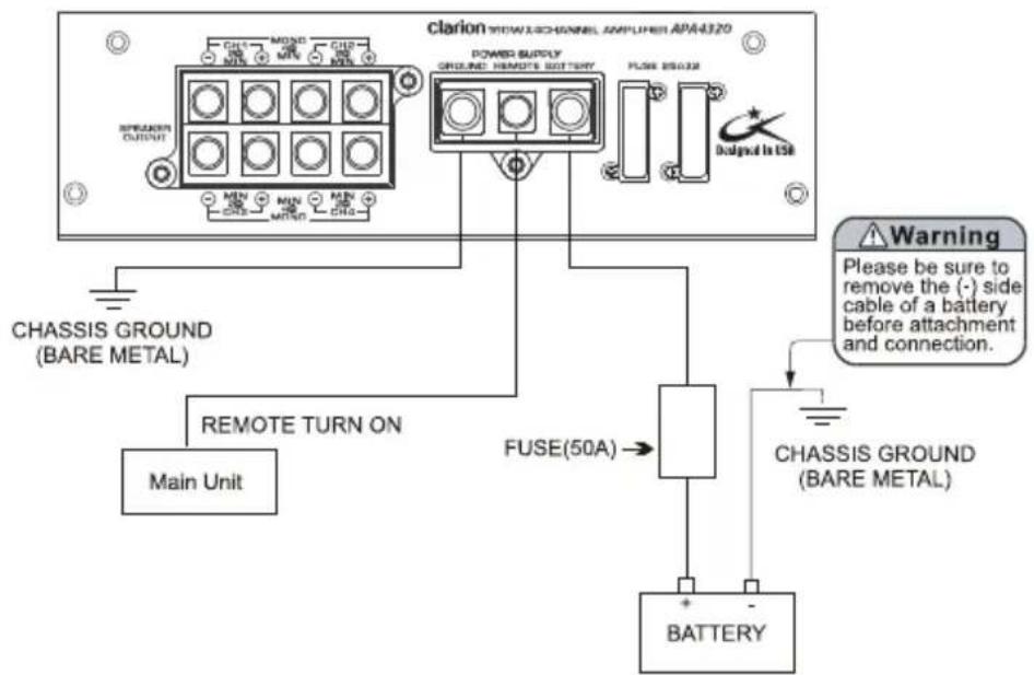
This Clarion Amplifier Designed for On-road Vehicle (DC 12V) Purpose.
This section lists mounting and wiring precautions for installing the Clarion APA4320 car audio amplifier. Combined with the experience of a professional installer, these safeguards are sufficiently detailed to successfully complete installation. If you do not have the necessary skills, do not install the amplifier yourself. Instead, see your authorized Clarion dealer for installation recommendations.
Mounting Precaution
- Although this Clarion amplifier incorporates a large heat sink and protection circuits, mounting any amplifier in a confined space without any air movement can still damage internal circuits over time. Choose a site that provides adequate ventilation around the amplifier. For easy system setup, mount the amplifier so the controls and fuse will be accessible after installation.
- When you attach this product, please choose the place distant as much as possible from the Antenna of vehicles. When it attaches near the antenna of vehicles, a noise may occur.
In Addition, Observe These Precautions:
- For the most efficient cooling, mount the amplifier so cool air runs along the length of the heatsink. Remember, any moving air will dissipate heat.
- Mount the amplifier on a rigid surface. Do not install the amplifier on plastic or other combustible material.
- Prior to drilling, make sure proposed mounting holes will not cut into the fuel tank, fuel lines, brake lines (under chassis), or electrical wiring.
Wiring Precautions
- Read all wiring precautions. If you are not sure of the connections, contact your authorized Clarion dealer.
- Before installation, make sure the main unit power switch is turned OFF.
- Disconnect the negative (-) lead at the battery before making any power connections.
- When making connections, be sure that each connection is clean and secure. Insulate final connections with electrical tape or shrink tubing. Failure to do so may damage your equipment.
- A secure, clean ground connection is critical to the performance of your Clarion car audio amplifier. Use the shortest ground wire possible to minimize resistance and avoid noise problems.
- Add an external fuse (50A) on the positive (+) power lead and connect it as close as possible to the vehicle's (+) battery terminal. Adding an external fuse will protect the electrical system from short-circuits that can cause fire.
- Refer to Figure — "Electrical connections" when making electrical connections. Connect the amplifier's positive (+) power lead via a fuse directly to the positive (+) terminal on the car battery. Do not connect this wire to the car's fuse panel. Use red-insulated 8-gauge wire for the amplifier's positive (+) power lead and the same gauge black-insulated wire for the ground.
- Since the speaker output terminal and power supply terminal of this product are block-type terminals, the tip of each connection code should make connection after about 1cm strip processing of the wire. To avoid short circuit, please tightly lock the terminal when doing the wiring. Also regular inspection is recommended on terminal for loosen connection.
- When replacing the amplifier's fuse, always use one having the same current rating (50A). Substituting with a higher-rated fuse can reduce protection and may result in serious damage to the amplifier.
- Never ground the speakers to the vehicle chassis or body.
- Make sure that your vehicle's electrical system (i.e., alternator, battery, etc.) is capable of handling the additional load.
- To avoid possible noise problems, run the amplifier's positive (+) power lead along one side of the vehicle to the battery. Run the remote turn-on wire and RCA audio cable down the center, and route the speaker wires along the remaining side. If wires must cross, run them perpendicular to each other.
- When creating passage holes for the power wire, use grommets to eliminate any sharp edges created during drilling. This will protect the wire from bring nicked and causing a short-circuit.
- Extra cable cause signal loss and act as an "antenna" for noise. Use only high-quality RCA cables that are no longer than necessary to make a direct connection with the main unit or equalizer.
■ Cautions on Installation
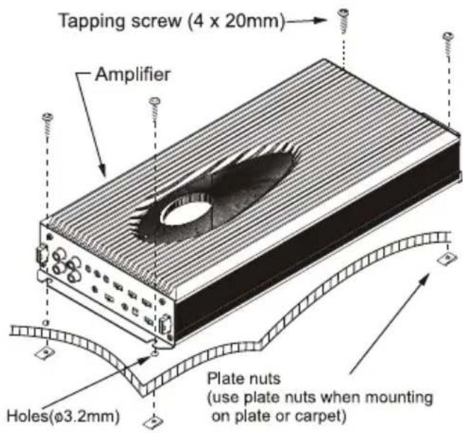
- Be sure to use the screws supplied with the amplifier to install it in your car. Mounting the unit using screws other than those supplied may lead to malfunctioning of the unit.
- When you mount the unit, be careful not to damage the wiring in your car with tools or parts such as tapping screws.
■ Installation Procedure
- Open four holes ( 3.2mm) to mount the unit.
- Use the four tapping screws (4x20mm) to secure the unit.
- When mounting the unit on a plastic plate or carpet, use the plate nuts.
■ After Installation
Battery connection. It checks once again whether there is any error in connection
and attachment, and the end terminal of a cable is connected to the (-) side terminal of a battery.
5. APPLICATIONS
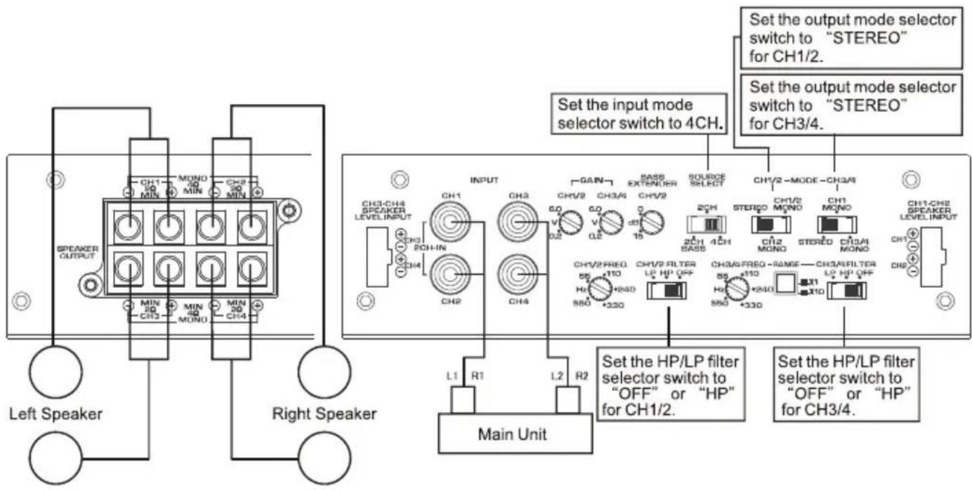
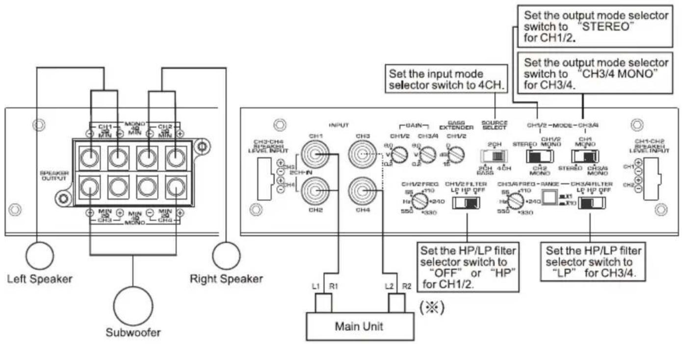
4 Channel Input
■ 4 Channel Mode
(※)Caution :
① When the subwoofer output terminal is beforehand connected to the main unit, please connect the sudwoofer output to CH3 or CH4.
② When a main unit uses amplifier in 3CH mode with 4CH mode output, please connect L2 To CH3, R2 to CH4.
2 Channel Input
4 Channel Mode
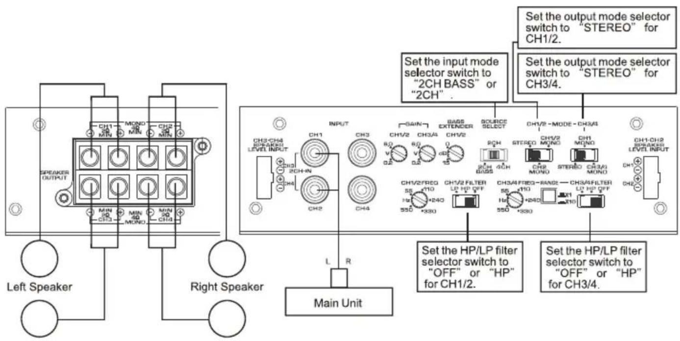
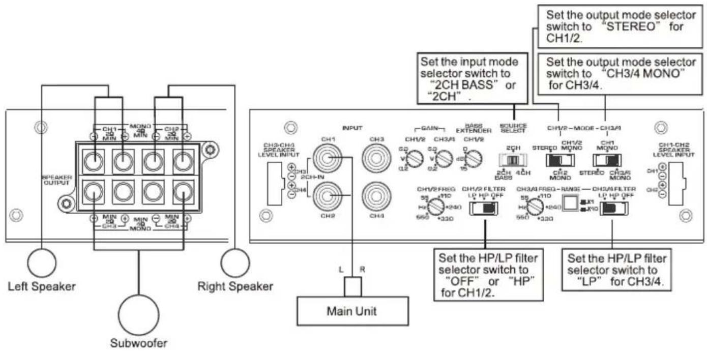
■ 2 Channel Mode
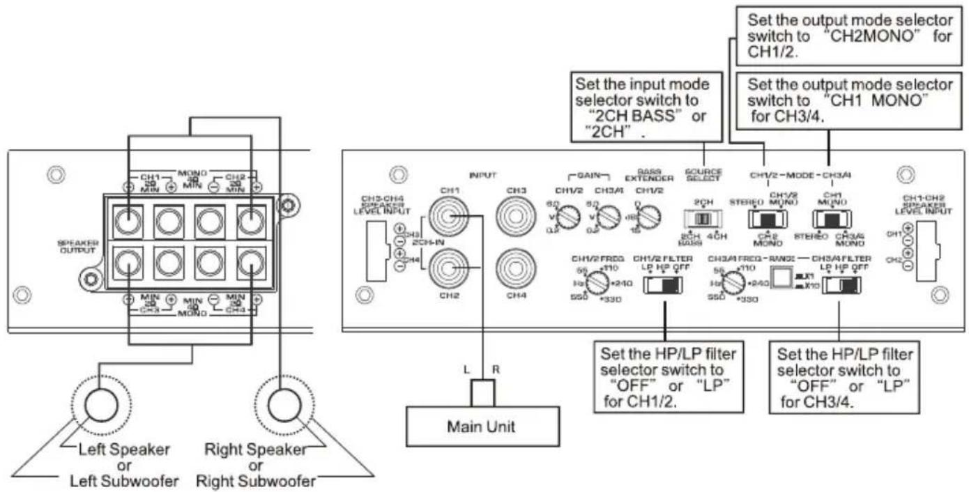
Caution:
When Subwoofer starts "pop" (electrical overload), please lower gain control volume and avoid the damage to subwoofer. If the sound of subwoofer begins to produce muddiness and distortion (amplifier allophone), please lower gain control volume, avoid that amplifier lapses into a regular functional stop state by fault load, and wait to recover clear low-pitched sound region sensitivity.
Adjustment of an electronic crossover function (HP / LP):
Caution:
Clarion recommends turning the amplifier off before changing any switch position.
This will eliminate any possible damage from transient spikes to the amplifier or speaker system while changing the switch setting.
(1) HP filter functional (mid-range / high region speaker correspondence) setup :
LPF/HPF control set to 125Hz is recommended. Listen to a variety of music style (Rock, Rap, R&B, etc...) and slowly increase or decrease the LPF/HPF control until the best performance is realized. For most a mid range speaker, the crossover point tends to be around 100Hz. Setting the crossover frequency too low may cause distortion is produced on a high reproduction level. In addition to it, there is a possibility of damaging usage's speaker. If such a situation occurs, please raise crossover frequency (please turn LPF/HPF control unit adjustment volume clockwise), and reduce distortion.
(2) LP filter function (subwoofer correspondence) setup :
LPF/HPF control set to 55Hz (the position turned to the limit of a counterclockwise rotation)
is recommended. Listen to a variety of music style (Rock, Rap, R&B, etc...) and slowly increase or decrease the LPF/HPF control until the best performance is realized. For most subwoofer systems, the crossover point tends to be between 55Hz and 120Hz.
Setting the crossover frequency too high may cause audio system to sound "boomy" or vocals and speech to become very "nasal" in tone.
Speaker Level Input
When you connect with a car audio without a RCA output terminal, please use a speaker level input terminal.
Caution:
Noise or pop sound may be made by a car audio to combine with this amplifier or by a position of a level of gain of this amplifier.
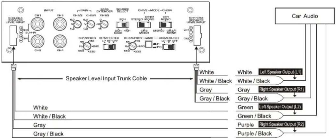
flowchart
graph TD
    A["Speaker Level Input Trunk Cable"] --> B["White"]
    A --> C["Gray"]
    A --> D["Green"]
    A --> E["Purple"]
    A --> F["Car Audio"]
    B --> G["White / Black"]
    C --> H["Gray / Black"]
    D --> I["Green / Black"]
    E --> J["Red / Black"]
    F --> K["Red / Black"]
    style A fill:#f9f,stroke:#333
    style B fill:#ccf,stroke:#333
    style C fill:#ccf,stroke:#333
    style D fill:#ccf,stroke:#333
    style E fill:#ccf,stroke:#333
    style F fill:#ccf,stroke:#333
6. FINAL SYSTEM CHECKS
- Start the engine and turn on the main unit. After a short two-second delay, slowly raise the volume and listen to the sound. If you hear any noise, static, distortion or no sound at all, check the connections, and also refer to the “Troubleshooting” section. Depending on your system design, the levels may become quite loud even care when adjusting the controls.
- Adjust the balance control from left to right and listen to the result. Audio imaging
Should match control setting.
- Increase the volume and verify that the APA4320 amplifier reproduces audio without distortion at all frequencies. If you hear distortion, check the connections and verify that the gain controls is set correctly. Another possibility is damaged (or under-powered) speakers. Once again, refer to the "Troubleshooting" section for additional help.
7. TROUBOLESHOOTING
| PROBLEM | POSSIBLE CAUSE | SOLUTION |
| No audio | Low or no turn-on voltage | Check remote connections at amplifier and main unit. |
| Blown fuse | Replace with new fast-blow fuse(same rating). | |
| Power wires not connected | ·Check power and ground connection at amplifier.·Check battery connections. | |
| Speakers not connected or blown | ·Check speaker connections at amplifier.·Measure coil impedance. | |
| Audio cycles on and off | Thermal protection circuits are shutting amplifier off | ·Check location for adequate ventilation.·Consult an authorized Clarion dealer. |
| Distored Sound | Gain controls is not set properly, or damaged speaker cones | ·Adjust gain control.·Check each speaker cone for signs of damage(e.g., frozen cone, burning smell, etc). |
| Sound lacks punch | Speakers wired incorrectly, which causes cancellation of bass frequencies | Check polarity of wires from amplifier to each speakers as illustrated in connection examples. |
| Whining or ticking noise in the sound with engine on | Amplifier is picking up alternator noise or radiated noise | ·Check power and ground connections on amplifier.·Check or move audio cables.·Install an in-line noise filter on main unit's power wire.·Check alternator and / or voltage regulator.·Test for weak battery or add water to battery. |
8. SPECIFICATIONS
| Rated Output | :80Wx4(4-channel mode)(20Hz~20kHz,0.05%,4Ω,4-channel simultaneous output)80Wx2+230Wx1(3-channel mode)230Wx2(2-channel mode) |
| Maximum Power | :160Wx4 |
| Frequency Response | :10Hz~50kHz(+/-1.0dB) |
| Harmonic Distortion | :0.025%(1kHz,10W,4Ω) |
| S/N Rate | :100dB |
| Applicable Speaker Impedance | :4Ω (2Ω~8Ω) |
| Input Sensibility | :200mV~6,000mV |
| Power Source Voltage | :14.4V |
| Ground | :Negative |
| Power Consumption | :37A(with 80Wx4 rated output)1.6A(amplifier ON,no input) |
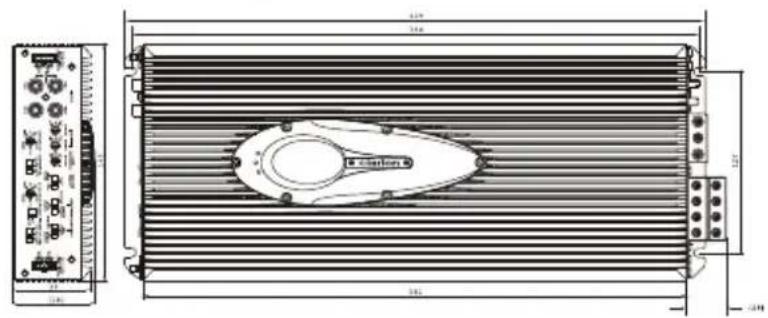
| External Dimensions | :165(W)x56(H)x409(D)mm |
| Weight | :3.9Kg |
※For improvement purposes, specifications and design are subject to change without prior notice.
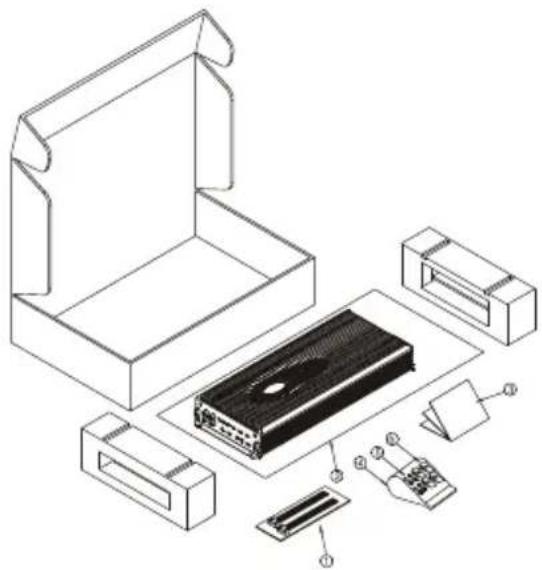
-9. PACKAGING CONTENT
| Number | Name | Quantity |
| 1 | Speaker Level Input Trunk Cable | 2 |
| 2 | Polyethylene Bag | 1 |
| 3 | User's Manual | 1 |
| 4 | Polyethylene Bag | 1 |
| 5 | Tapping Screw(4 x 20mm) | 4 |
| 6 | Plate Nut | 4 |
natural_image
Exploded view diagram of an electronic device showing internal components like a box, connectors, and a circuit board (no text or labels)
- clarion
- APA4320
- -1. INTRODUCTION
- 1) Strong Power Supply
- 2) Designed for high sound quality
- 3) Low distortion and wide output range.
- 4) Output Mode Selector
- 5) High pass/Low pass variable electronic crossovers
- 7) Protection circuit.
- 2
- AMPLIFIER CONTROLS AND POWER INDICATOR CONNECTIONS
- Front Panel Layout
- Gain Control
- INPUT Mode Selector Switch
- NOTE
- INSTALLATION
- Electrical Connections
- This Clarion Amplifier Designed for On-road Vehicle (DC 12V) Purpose.
- Mounting Precaution
- In Addition, Observe These Precautions:
- Wiring Precautions
- APPLICATIONS
- Channel Input
- Channel Input
- Caution:
- FINAL SYSTEM CHECKS
- TROUBOLESHOOTING
- SPECIFICATIONS
- -9. PACKAGING CONTENT
Marke : CLARION
Modell : APA4320
Kategorie : Autoradio