CT90 (1979) - Motorrad Honda - Kostenlose Bedienungsanleitung
Finden Sie kostenlos die Bedienungsanleitung des Geräts CT90 (1979) Honda als PDF.

| Produkttyp | Motorrad |
| Marke | Honda |
| Modell | CT90 (1979) |
| Motor | Einzylinder-Viertakt, 89 cm³ |
| Leistung | ca. 8 PS (5,9 kW) bei 8.500 U/min |
| Kühlung | Luftkühlung |
| Getriebe | 4-Gang manuell |
| Kraftübertragung | Kette |
| Rahmen | Stahlrohrrahmen |
| Vorderradfederung | Teleskopgabel |
| Hinterradfederung | Schwinge mit Federbeinen |
| Bremsen vorne | Trommelbremse |
| Bremsen hinten | Trommelbremse |
| Kraftstoffsystem | Vergaser |
| Kraftstofftank | ca. 5,5 Liter |
| Reifengröße vorne | 2.75-21 |
| Reifengröße hinten | 3.00-18 |
| Gesamtlänge | ca. 1.960 mm |
| Gesamtbreite | ca. 800 mm |
| Sitzhöhe | ca. 790 mm |
| Leergewicht | ca. 95 kg |
| Zündung | Magnetzündung |
| Batterie | 6V |
| Bedienungsanleitung | Kostenloser Download als PDF |
Häufig gestellte Fragen - CT90 (1979) Honda
Benutzerfragen zu CT90 (1979) Honda
0 Frage zu diesem Gerät. Beantworten Sie die, die Sie kennen, oder stellen Sie Ihre eigene.
Eine neue Frage zu diesem Gerät stellen
Laden Sie die Anleitung für Ihr Motorrad kostenlos im PDF-Format! Finden Sie Ihr Handbuch CT90 (1979) - Honda und nehmen Sie Ihr elektronisches Gerät wieder in die Hand. Auf dieser Seite sind alle Dokumente veröffentlicht, die für die Verwendung Ihres Geräts notwendig sind. CT90 (1979) von der Marke Honda.
BEDIENUNGSANLEITUNG CT90 (1979) Honda
Official
HONDA
SHOP MANUAL
CT90·110

natural_image
Illustration of a vintage motorcycle with blue outline and white frame, no visible text or symbolsCT90 '77-'79
CT110'80-'82
© HONDA MOTOR CO., LTD. 1982
PRINTED IN USA
6110205
IPC H A 5009802C
Thank you for your patronage.
This CD was purchased from @home backup. If it was purchased or obtained by any other means, you have illegally obtained this CD and are in violation of it copyrights.
Report copyright violations to:
@home backup
Attn: Manual Backups
2902 Grasmere St.
Garland, TX 75040
Unauthorized duplication or distribution is strictly prohibited.
INTRODUCTION
This shop manual contains service information and procedures for 1977 through 1979 CT90's and 1980 through 1982 Honda CT110's. Motorcycles manufactured after December 31, 1977 are equipped with emission controls. These are covered in this shop manual, in Section VII ('78½ EMISSIONS ADDENDUM).
CT110 service information begins on page 141.
ALL INFORMATION, ILLUSTRATIONS, DIRECTIONS AND SPECIFICATIONS INCLUDED IN THIS PUBLICATION ARE BASED ON THE LATEST PRODUCT INFORMATION AVAILABLE AT THE TIME OF APPROVAL FOR PRINTING. HONDA MOTOR CO., LTD. RESERVES THE RIGHT TO MAKE CHANGES AT ANY TIME WITHOUT NOTICE AND WITHOUT INCURRING ANY OBLIGATION WHATEVER.
NO PART OF THIS PUBLICATION MAY BE REPRODUCED WITHOUT WRITTEN PERMISSION.
HONDA MOTOR CO., LTD.
Service Publications Office
CONTENTS
I SPECIFICATIONS. 3
II SERVICE INFORMATION
- SERVICE DATA 5
- TORQUE SPECIFICATIONS 7
- SPECIAL TOOLS 8
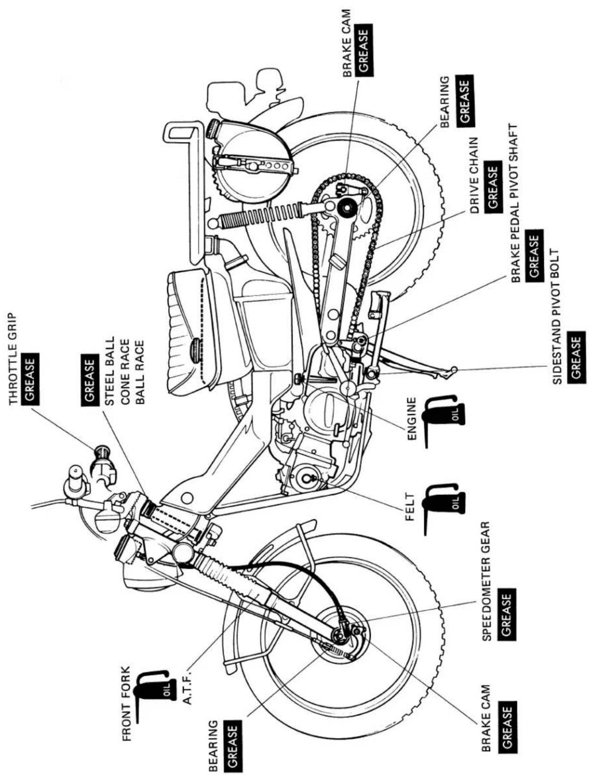
- LUBRICATION POINTS 9
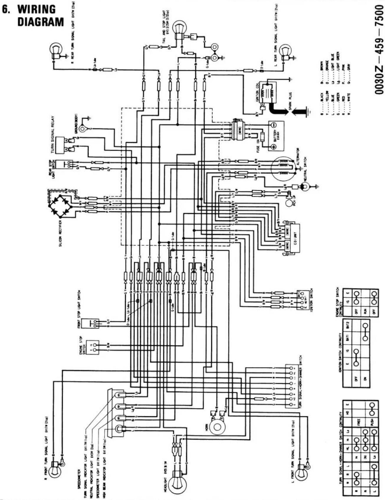
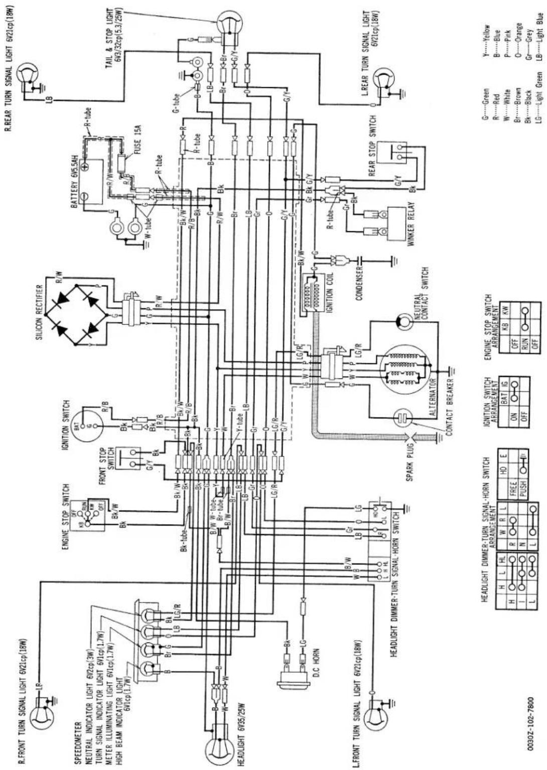
- WIRING DIAGRAM 10
- TROUBLE SHOOTING CHART 11
- MAINTENANCE SCHEDULE 20
III INSPECTION/ADJUSTMENT 22
IV ENGINE
- ENGINE REMOVAL/INSTALLATION 36
- CYLINDER HEAD/VALVES 38
- CYLINDER/PISTON 50
- LUBRICATION SYSTEM 56
- CLUTCH/GEAR SHIFT/OIL PUMP 57
- AUXILIARY TRANSMISSION 65
- A.C. GENERATOR/CAM CHAIN TENSIONER 68
- TRANSMISSION/CRANKSHAFT/KICK STARTER 71
- CARBURETOR 78
V FRAME
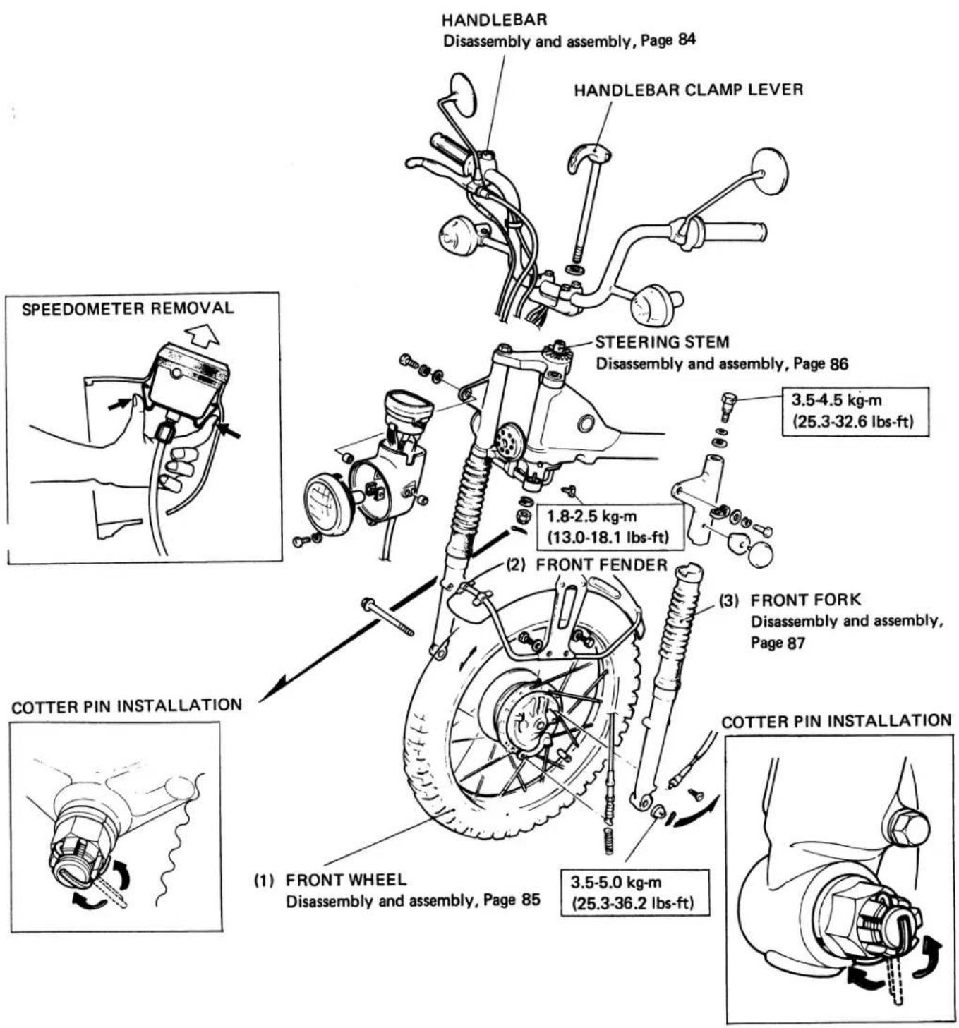
- FRONT WHEEL/FRONT SUSPENSION/STEERING 83
- REAR WHEEL/REAR SUSPENSION 90
- TAIL LIGHT/FUEL TANK 96
- WIRING 97
VI ELECTRICAL
- BATTERY CHARGING SYSTEM 99
- IGNITION SYSTEM 103
- SWITCHES 106
VII '78½ EMISSIONS ADDENDUM 109
VIII '79 ADDENDUM 137
IX '80 CT110 ADDENDUM 141
X '81 CT110 ADDENDUM 171
XI '82 CT110 ADDENDUM 185
| Items | Specifications |
| DIMENSION | |
| Overall Length | 1,870 mm (73.6 in) |
| Overall Width | 740 mm (29.1 in) |
| Overall Height | 1,060 mm (41.7 in) |
| Wheel Base | 1,220 mm (48.0 in) |
| Seat Height | 775 mm (30.5 in) |
| Ground Clearance | 165 mm (6.5 in) |
| Dry Weight | 90 kg (198.5 lb.) |
| FRAME | |
| Type | Back bone |
| Front Suspension, Travel | Telescopic fork, 102 mm (4.0 in) |
| Rear Suspension, Travel | Swing arm, 77 mm (3.0 in) |
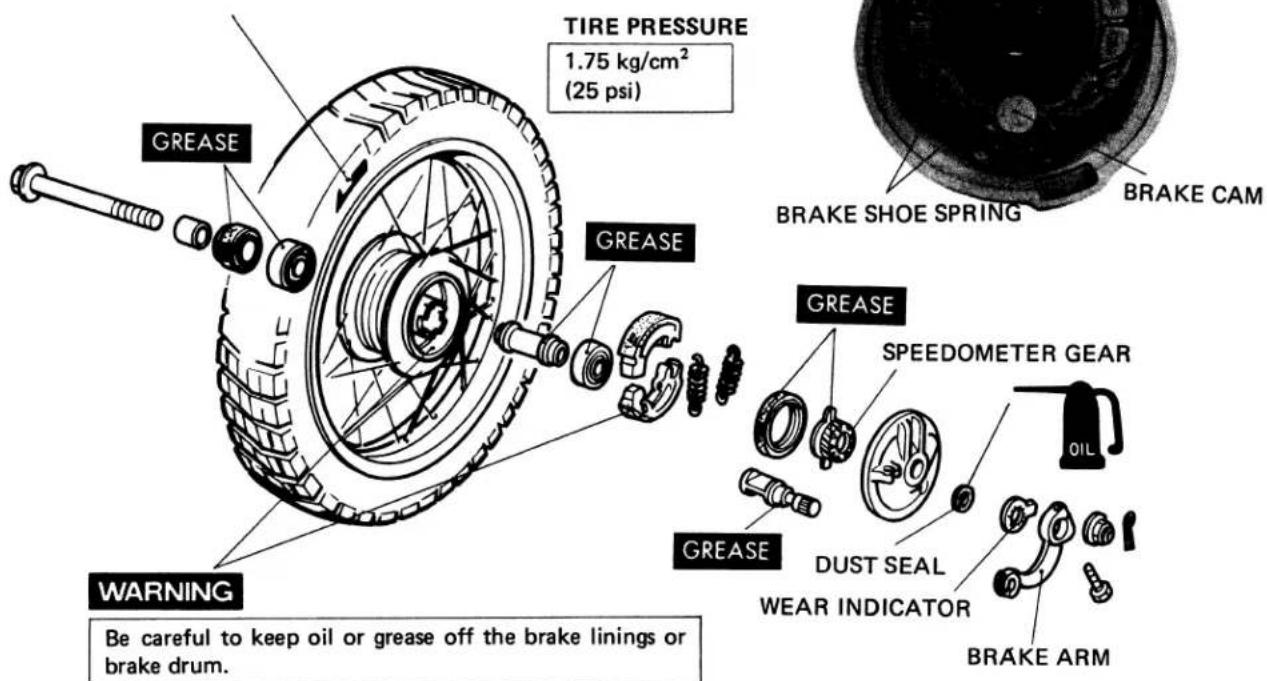
| Front Tire Size, Type | 2.75-17-4 PR Knobby, tire air pressure 1.75 kg/cm^2 (25 psi) |
| Rear Tire Size, Type | 2.75-17-4 PR Knobby, tire air pressure 2.25 kg/cm^2 (32 psi) |
| Front Brake | Internal expanding shoes |
| Rear Brake | Internal expanding shoes |
| Fuel Capacity | 5.5 lit. (1.4 U.S. gal. 1.21 Imp. gal.) |
| Fuel Reserve Capacity | 0.8 lit. (0.2 U.S. gal. 0.18 Imp. gal) |
| Auxiliary Fuel Tank Capacity | 2.3 lit. (0.6 U.S. gal. 0.54 Imp. gal) |
| Caster Angle | 63^ |
| Trail Length | 75 mm (3 in) |
| Front Fork Oil Capacity | 125 - 135 cc (4.2 - 4.6 ozs.)To fill dry fork assembly130 - 140 cc (4.4 - 4.7 oz.)To refill after draining120 - 130 cc (4.1 - 4.4 oz.) |
| ENGINE | |
| Type | Air cooled 4-stroke O.H.C. engine |
| Cylinder Arrangement | Single cylinder 75 inclined from vertical |
| Bore and Stroke | 50 x 45.6 mm (1.970 x 1.797 in) |
| Displacement | 89.5 cc (5.46 cu in) |
| Compression Ratio | 8.2 : 1 |
| Carburetor, Venturi Dia. | Piston valve type, venturi dia. 16 mm (0.64 in) |
| Valve train | Chain driven over head camshaft |
| Oil Capacity | 0.9 lit. (0.95 U.S. qt. 0.80 Imp. qt.) |
| Lubrication System | Forced pressure and wet sump |
| Fuel Required | Low-lead or regular gasoline of 91 research octane(86 pump octane) or higher |
| Air Filtration | Oiled polyurethane foam filter |
[ ] k9 (1978) model
| Items | Specifications |
| Intake Valve: OpensClosesExhaust Valve: OpensClosesValve ClearanceEngine Dry WeightAir Screw OpeningPilot Screw OpeningIdle Speed | 5° BTDC20° ABDC25° BBDC5° ATDCIN/EX. 0.05 mm (0.002 in)24 kg (52.9 lb.)1[1-1/4]1,300 rpm |
| DRIVE TRAINClutchTransmissionPrimary ReductionGear Ratio IIIIIIIVAuxiliary Transmission High/LowFinal ReductionGear Shift Pattern | Wet multi plate automatic4-speed constant mesh3.7222.5381.6111.1900.9581.000 / 1.8673.000, drive sprocket 15 T, driven sprocket 45 TLeft foot operated return system |
| ELECTRICALIgnitionIgnition Advance :“ F ” markMax. advanceStarting SystemAlternatorBattery CapacityFuse CapacitySpark PlugCondenser Capacity | Battery and ignition coil1,300 rpm10° TDC26° - 32°Kick starterA.C. Generator 0.062 kw/6,000 rpm6 V - 5.5 AH15 amp.U.S.A. modelD8HA (NGK), X24FS-U (ND)Canada modelDR8HS (NGK), X24FSR-U (ND)0.27 - 0.33 μF |
ENGINE
Unit: mm (in.)
| Item | Standard | Service Limit | ||||
| Cylinder | I.D. | 50.00-50.01 | (1.9685 - 1.9689) | 50.10 (1.9724) | ||
| Taper | 0 - 0.01 | (0 - 0.0004) | 0.05 (0.002) | |||
| Out-of-round | 0 - 0.01 | (0 - 0.0004) | 0.05 (0.002) | |||
| Piston O. D. | 49.97-49.99 | (1.9673 - 1.9681) | 49.80 (1.9606) | |||
| Piston pin I. D. | 14.002-14.008 | (0.5513 - 0.5515) | 14.04 (0.5528) | |||
| Piston pin O. D. | 13.994-14.000 | (0.5509 - 0.5512) | 13.960 (0.5496) | |||
| Piston ring end gap | Top/second | 0.15-0.35 | (0.006 - 0.014) | 0.50 (0.020) | ||
| Oil | 0.15-0.40 | (0.006 - 0.016) | 0.50 (0.020) | |||
| Piston-to-piston ring clearance | Top/second | 0.010-0.045 | (0.0004 - 0.0018) | 0.12 (0.0047) | ||
| Oil | 0.010-0.045 | (0.0004 - 0.0018) | 0.12 (0.0047) | |||
| Piston ring thickness | Top/second | 1.175-1.190 | (0.0463 - 0.0469) | 1.130 (0.0445) | ||
| Oil | 2.475-2.490 | (0.0974 - 0.0980) | 2.43 (0.957) | |||
| Valve stem O. D. | IN | 5.455-5.465 | (0.2148 - 0.2152) | 5.435 (0.2139) | ||
| EX | 5.435-5.445 | (0.2140 - 0.2144) | 5.415 (0.2132) | |||
| Valve guide I. D. | IN/EX | 5.475-5.485 | (0.2157 - 0.2161) | 5.525 (0.2175) | ||
| Valve-to-valve guide clearance | IN | 0.010-0.030 | (0.0004 - 0.0012) | 0.08 (0.0032) | ||
| EX | 0.030-0.050 | (0.0012 - 0.0020) | 0.10 (0.0040) | |||
| Valve spring | Free length | Outer | 31.8 | (1.252) | 30.6 (1.205) | |
| Inner | 26.5 | (1.043) | 25.5 (1.004) | |||
| Preload/length | Outer kg/mm (lbs./in.) | 19-21/22.3 | (41.8-46.21/0.878) | — | ||
| Inner kg/mm (lbs./in.) | 9.5-10.5/18.4 | (20.9-23.1/0.724) | — | |||
| Valve face width | IN/EX | 1.2-1.5 | (0.048 - 0.060) | 1.8 (0.072) | ||
| Valve seat width | IN/EX | 1.0 | (0.04) | 1.6 (0.064) | ||
| Cam height | IN/EX | 24.90-24.98 | (0.9803 - 0.9835) | 24.6 (0.9685) | ||
| Camshaft O. D. | R. End | 17.927-17.938 | (0.7058 - 0.7062) | 17.90 (0.7047) | ||
| L. End | 25.917 - 25.930 | (1.0204 - 1.0209) | 25.90 (1.0197) | |||
| Camshaft end bearing I. D. | R. End | 18.000-18.018 | (0.7087 - 0.7094) | 18.05 (0.7106) | ||
| L. End | 26.000-26.020 | (1.0236 - 1.0244) | 26.05 (1.0256) | |||
| Clutch disc thickness | 2.8-2.9 | (0.1102 - 0.1142) | 2.4 (0.0945) | |||
| Clutch plate thickness | 1.93-2.07 | (0.0760 - 0.0815) | 1.85 (0.0729) | |||
| Clutch plate warpage | 0.2 | (0.008) | 0.5 (0.02) | |||
| Clutch spring | Free length | 27.0 | (1.0630) | 26.0 (1.0236) | ||
| Preload/length kg/mm (lbs/in) | 10-10.4/15 | (22-22.9/0.591) | — | |||
| Crankshaft run out (at ends) | 0 - 0.015 | (0 - 0.0006) | 0.10 (0.0040) | |||
| Crankshaft bearing play | Axial | 0.10-0.35 | (0.004 - 0.019) | 0.8 (0.032) | ||
| Radial | 0. - 0.01 | (0. - 0.0004) | 0.05 (0.002) | |||
| Connecting rod small end I. D. | 14.012-14.028 | (0.5517- 0.5523) | 14.050 (0.5531) | |||
| Connecting rod big end side clearance | 0.10-0.35 | (0.004 - 0.019) | 0.8 (0.032) | |||
| Connecting rod big end radial clearance | 0 - 0.01 | (0 - 0.0004) | 0.05 (0.002) | |||
| Clutch drive gear I.D. | 24.00-24.02 | (0.9449 - 0.9457) | 24.15 (0.9508) | |||
| Clutch center guide O.D | 22.0-22.1 | (0.8661 - 0.8701) | 21.85 (0.8602) | |||
| Clutch center guide-to-crankshaft clearance | 0.005-0.047 | (0.0002 - 0.0019) | 0.15 (0.0060) | |||
| Item | Standard | Service Limit | |||
| Rocker arm shaft O. D. | 9.972–9.987 | (0.3926 – 0.3932) | 9.92 | (0.3906) | |
| Rocker arm I. D. | 10.000–10.015 | (0.3937 – 0.3943) | 10.10 | (0.3976) | |
| Primary drive gear I. D. | 24.00–24.02 | (0.945 – 0.946) | 24.15 | (0.951) | |
| Crankshaft-to-clutch center guide clearance | 0.005–0.047 | (0.0002 – 0.0019) | 0.15 | (0.060) | |
| Tensioner spring free length | Spring A | 65 | (2.6) | 60 | (2.4) |
| Spring B | 49.8 | (19.92) | 40 | (1.6) | |
| Oil pump | Inner-to-outer rotor clearance | 0.15 | (0.006) | 0.2 | (0.008) |
| Outer rotor-to-body clearance | 0.15–0.20 | (0.0060 – 0.0080) | 0.25 | (0.010) | |
| Rotor-to-cover clearance | 0.02–0.07 | (0.0008 – 0.0028) | 0.12 | (1.0047) | |
| Shift fork I. D. | 42.00 | (1.6535) | 42.1 | (1.6575) | |
| Shift fork ends thickness | 5.96–6.04 | (0.2346 – 0.2378) | 5.70 | (0.2244) | |
| Shift drum O. D. | 41.950–41.975 | (1.6516 – 1.6526) | 41.80 | (1.6457) | |
| Shift drum groove width | 6.1–6.2 | (0.2402 – 0.2441) | 6.4 | (0.2520) | |
| Shift fork-to-shift drum clearance | 0.05 | (0.0020) | 0.2 | (0.008) | |
| Auxiliary transmission | Idler gear shaft O. D. | 12.966–12.984 | (0.5105 – 0.5112) | 12.85 | (0.5140) |
| Idler gear I. D. | 13.000–13.018 | (0.5200 – 0.5207) | 13.10 | (0.5157) | |
FRAME
| Item | Standard | Service Limit | |||
| Front/rear axle shaft bend | 0 - 0.05 | (0 - 0.002) | 0.2 | (0.008) | |
| Front/rear wheel bearing play | Axial | 0 - 0.05 | (0 - 0.002) | 0.1 | (0.004) |
| Radial | 0.003-0.008 | (0.0001 - 0.0003) | 0.04 | (0.0016) | |
| Front/rear brake drum I. D. | 110.0 | (4.3307) | 111.0 | (4.3701) | |
| Wheel rim | Face runout | 0 - 0.5 | (0 - 0.02) | 1.0 | (0.04) |
| Eccentricity | 0 - 0.5 | (0 - 0.02) | 1.0 | (0.04) | |
| Front fork spring | Free length | 203 | (8.0) | 185 | (7.3) |
| Rear shock absorber spring | Free length | 223 | (8.78) | 207 | (8.16) |
| Front fork piston O. D. | 30.950-30.975 | (1.219 - 1.220) | 30.85 | (1.215) | |
| Front fork bottom case I. D. | 31.000-31.039 | (1.221 - 1.223) | 31.10 | (1.225) | |
| Brake lining thickness | 4.0 | (0.16) | 2.0 | (0.08) | |
ENGINE
| Tightening point | Q'ty | Thread dia. | Torque kg-m (lbs ft) |
| Cylinder head nut | 4 | 8 | 2.0 – 2.5 (14.5 – 18.1) |
| Camshaft sprocket bolt | 2 | 6 | 0.9 – 1.2 (6.5 – 8.7) |
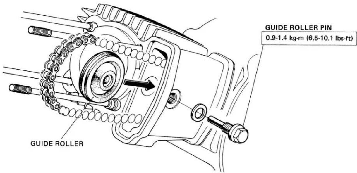
| Cam chain guide roller bolt | 1 | 6 | 0.9 – 1.4 (6.5 – 10.1) |
| Spark advancer bolt | 1 | 6 | 0.8 – 1.2 (5.8 – 8.7) |
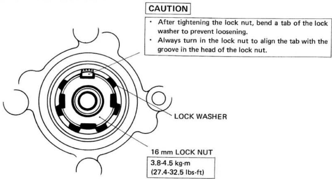
| Clutch lock nut | 1 | 16 | 3.8 – 4.5 (27.4 – 32.5) |
| A. C. generator rotor bolt | 1 | 8 | 2.6 – 3.2 (18.8 – 23.2) |
| A. C. generator stator bolt | 3 | 6 | 0.8 – 1.2 (5.8 – 8.7) |
| Shift drum bolt | 1 | 6 | 0.8 – 1.2 (5.8 – 8.7) |
FRAME
| Tightening point | Q'ty | Thread dia. | Torque kg-m (lbs-ft) |
| Handlebars setting bolts | 4 | 6 | 0.8 – 1.2 (5.8 – 8.7) |
| Steering stem nut | 1 | 22 | 6.0 – 7.0 (43.4 – 50.7) |
| Front fork bolt | 2 | 10 | 3.5 – 4.5 (25.3 – 32.6) |
| Steering bottom bridge bolt | 2 | 8 | 1.8 – 2.5 (13.0 – 18.1) |
| Swingarm pivot bolt | 1 | 10 | 4.0 – 6.0 (29.0 – 43.4) |
| Rear shock absorber upper nut | 2 | 10 | 2.5 – 3.5 (18.1 – 25.3) |
| Rear shock absorber lower nut | 2 | 8 | 2.5 – 3.5 (18.1 – 25.3) |
| Front axle nut | 1 | 10 | 3.5 – 5.0 (25.3 – 36.2) |
| Rear axle nut | 1 | 10 | 3.5 – 5.0 (25.3 – 36.2) |
| Rear axle sleeve nut | 1 | 16 | 3.5 – 4.5 (25.3 – 32.6) |
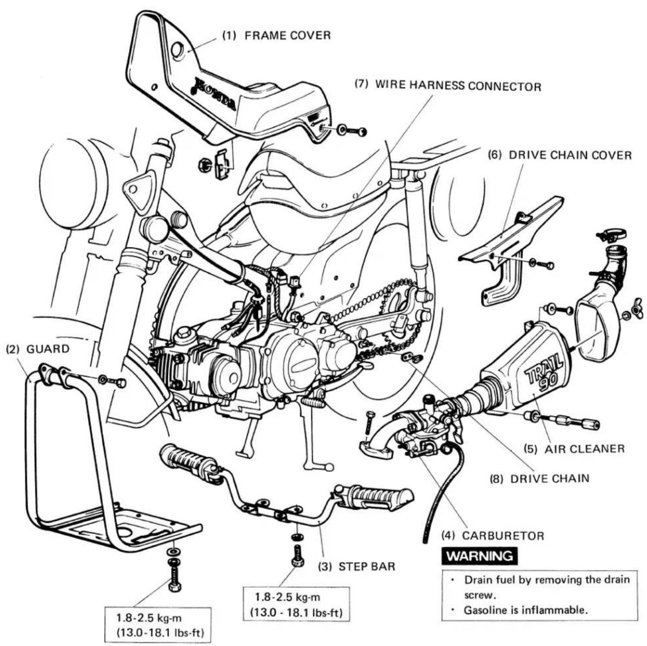
| Driven sprocket bolt | 4 | 8 | 1.8 – 2.5 (13.0 – 18.1) |
| Rear brake stop arm bolt | 2 | 8 | 1.8 – 2.5 (13.0 – 18.1) |
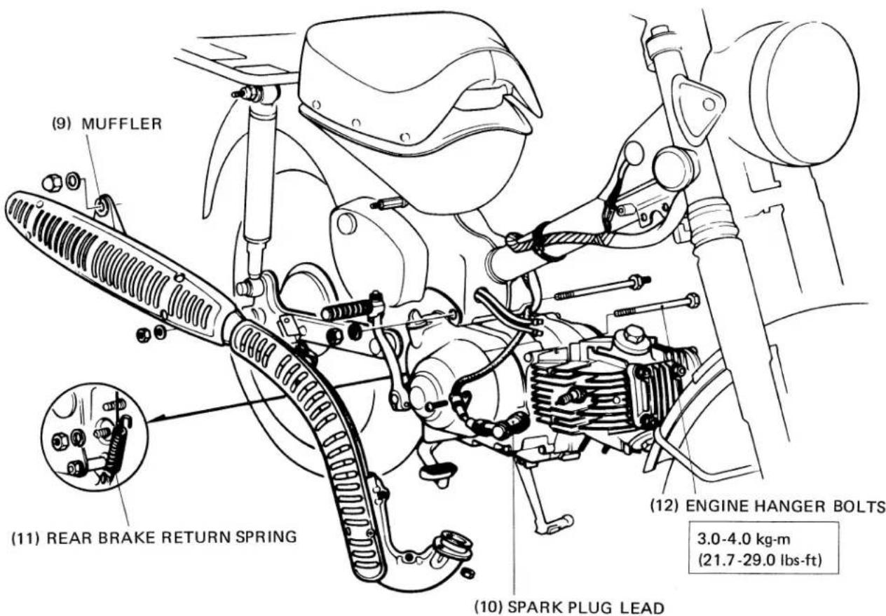
| Engine hanger bolt | 2 | 10 | 3.0 – 4.0 (21.7 – 29.0) |
| Step bar bolt | 14 | 8 | 1.8 – 2.5 (13.0 – 18.1) |
Torque specifications listed above are important tightening points. Others should be tightened to standard torque below.
Standard Torque Specifications
| Type | Torque kg-m (lbs-ft) | Type | Torque kg-m (lbs-ft) | ||
| 5 mm bolt and nut | 0.45 – 0.60 | (3.3 – 4.3) | 5 mm screw | 0.35 – 0.50 | (2.5 – 3.6) |
| 6 mm bolt and nut | 0.8 – 1.2 | (5.8 – 8.7) | 6 mm screw | 0.7 – 1.1 | (5.1 – 8.0) |
| 8 mm bolt and nut | 1.8 – 2.5 | (13.0 – 18.1) | 6 mm flange bolt and nut | 1.0 – 1.4 | (7.2 – 10.1) |
| 10 mm bolt and nut | 3.0 —4.0 | (21.7 – 29.0) | 8 mm flange bolt and nut | 2.4 – 3.0 | (17.4 – 21.7) |
| 12 mm bolt and nut | 5.0 —6.0 | (36.2 – 43.4) | 10 mm flange bolt and nut | 3.0 – 4.0 | (21.7 – 29.0) |
| TOOL NAME | PART NO. | REFERENCE PAGE |
| Float valve gauge | 07401 - 0010000 | 81 |
| 36mm pin spanner | 07902 - 0010000 | 86 |
| Tappet adjusting wrench | 07908 - 0010000 | 24 |
| Steering stem nut wrench | 07915 - 0300000 | 86 |
| 16mm lock nut wrench | 07916 - 3710000 | 58 |
| Clutch outer holder | 07932 - 0340000 | 58 |
| Rotor puller | 07933 - 2160000 | 69 |
| Valve guide driver | 07942 - 3290100 | 42 |
| Valve guide driver | 07942 - 1180100 | 42 |
| Valve spring compressor | 07957 - 3290001 | 41 |
| Valve guide reamer | 07984 - 0980000 | 42 |
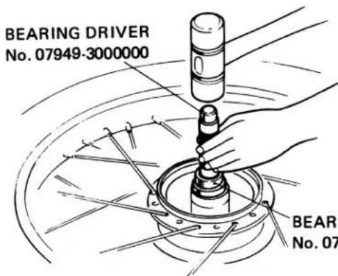
| Bearing driver | 07949 - 3000000 | 85, 91 |
| Bearing driver attachment | 07945 - 0980000 | 85, 91 |
| Bearing driver | 07949 - 6110000 | 92 |
| Bearing driver attachment | 07945 - 3330100 | 92 |
| Ball race driver | 07944 - 1150001 | 86 |
| Fork seal driver | 07974 - 1180001 | 87 |
| Oil seal guide | 07974 - 1280000 | 43 |
| Rear shock absorber dis/assembling tool | 07959 - 3290000 | 93 |
| Spring holder | 07967 - 1150100 | 93 |
A. ENGINE WILL NOT START (OR HARD STARTING)
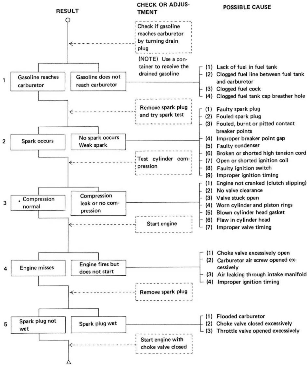
flowchart
graph TD
    A["1"] --> B["Gasoline reaches carburetor"]
    A --> C["Gasoline does not reach carburetor"]
    B --> D["2"]
    C --> E["3"]
    D --> F["Spark occurs"]
    D --> G["No spark occurs Weak spark"]
    E --> H["4"]
    H --> I["Engine misses"]
    H --> J["Engine fires but does not start"]
    H --> K["5"]
    J --> L["Spark plug not wet"]
    J --> M["Spark plug wet"]
    M --> N["START engine with choke valve closed"]
    N --> O["6"]
    O --> P["Flaw in cylinder head"]
    O --> Q["7"]
    P --> R["Flaw on shorted ignition coil"]
    Q --> S["Broken or shorted high tension cord"]
    R --> T["Open or shorted ignition switch"]
    S --> U["Faulty condenser"]
    T --> V["Faulty spark plug"]
    U --> W["Fouled spark plug"]
    V --> X["Lack of fuel in fuel tank"]
    W --> Y["Clogged fuel line between fuel tank and carburetor"]
    X --> Z["Clogged fuel cock"]
    Y --> AA["Clogged fuel tank cap breather hole"]
    Z --> AB["Remove spark plug and try spark test"]
    AA --> AC["Test cylinder compression"]
    AB --> AD["Start engine"]
    AC --> AE["Test cylinder compression"]
    AD --> AF["Start engine with choke valve closed"]
    AE --> AG["Start engine with choke valve closed"]
    AF --> AH["Start engine with choke valve closed"]
    AG --> AI["Start engine with choke valve closed"]
    AH --> AJ["Start engine with choke valve closed"]
    AI --> AK["Start engine with choke valve closed"]
    AJ --> AL["Start engine with choke valve closed"]
    AK --> AM["Start engine with choke valve closed"]
    AL --> AN["Start engine with choke valve closed"]
    AM --> AO["Start engine with choke valve closed"]
    AN --> AP["Start engine with choke valve closed"]
B. ENGINE LACKS POWER (AUX. TRANSMISSION OPERATES PROPERLY)
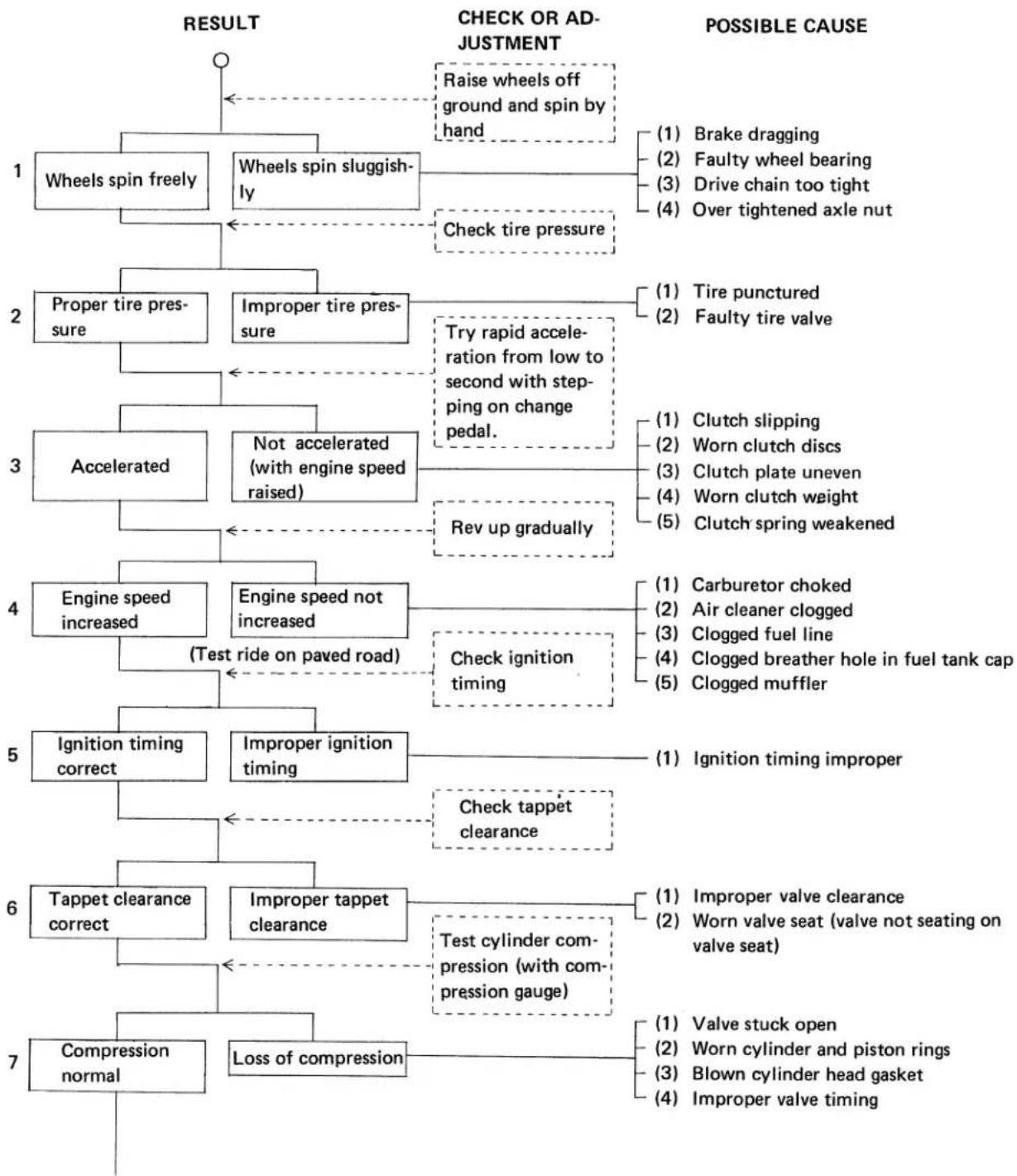
flowchart
graph TD
    A["1"] --> B["Wheels spin freely"]
    A --> C["Wheels spin sluggishly"]
    A --> D["Check tire pressure"]
    B --> E["2"]
    C --> F["3"]
    D --> G["4"]
    E --> H["1: Brake dragging"]
    E --> I["2: Faulty wheel bearing"]
    E --> J["3: Drive chain too tight"]
    E --> K["4: Over tightened axle nut"]
    F --> L["1: Tire punctured"]
    F --> M["2: Faulty tire valve"]
    G --> N["3: Clutch slipping"]
    G --> O["4: Worn clutch discs"]
    G --> P["5: Clutch plate uneven"]
    G --> Q["4: Worn clutch weight"]
    G --> R["5: Clutch spring weakened"]
    H --> S["4: Engine speed increased"]
    I --> T["5: Engine speed not increased"]
    J --> U["6: Test cylinder compression (with compression gauge)"]
    K --> V["7: Compression normal"]

    S --> W["1: Carburetor choked"]
    S --> X["2: Air cleaner clogged"]
    S --> Y["3: Clogged fuel line"]
    S --> Z["4: Clogged breather hole in fuel tank cap"]
    S --> AA["5: Clogged muffler"]

    W --> AB["1: Ignition timing improper"]
    X --> AC["2: Improper valve clearance"]
    Y --> AD["3: Worn valve seat (valve not seating on valve seat)"]
    Z --> AE["4: Blown cylinder head gasket"]
    AA --> AF["5: Improper valve timing"]

    subgraph RESULT
        direction TB
        B -->|Raise wheels off ground and spin by hand| B
        F -->|Try rapid acceleration from low to second with stepping on change pedal.| F
        G -->|Rev up gradually| G
        H -->|Engine speed not increased| H
        I -->|Check ignition timing| I
        J -->|Test ride on paved road| J
        K -->|Check tappet clearance| K
        L -->|Ignition timing correct| L
        M -->|Improper ignition timing| M
        N -->|Improper tappet clearance| N
        O -->|Loss of compression| O
        P -->|Reversed acceleration from low to second with stepping on change pedal.| P
        Q -->|Reversed acceleration from low to second with stepping on change pedal.| Q
        R -->|Reversed acceleration from low to second with stepping on change pedal.| R
        S -->|Improper tire pressure| S
        T -->|Not accelerated (with engine speed raised)| T
        U -->|Engine speed increased| U
        V -->|Engine speed not increased| V
        W -->|Ignition timing improved| W
        X -->|Improper ignition timing| X
        Y -->|Test cylinder compression (with compression gauge)| Y
        Z -->|Improper tire pressure| Z
        AA -->|Loss of compression| AA
        AB --> AB
        AC --> AB
        AD --> AB
        AE --> AB
        AF --> AB
        AG --> AB
        AH --> AB
        AI --> AB
        AJ --> AB
        AK --> AB
        AL --> AB
        AM --> AB
        AN --> AB
        AO --> AB
        AP --> AB
        AQ --> AB
        AR --> AB
        AS --> AB
        AT --> AB
        AU --> AB
        AV --> AB
        AW --> AB
        AX --> AB
        AY --> AB
        AZ --> AB
        BA --> AB
        BB --> AB
        BC --> AB
        BD --> AB
        BE --> AB
        BF --> AB
        BG --> AB
        BH --> AB
        BI --> AB
        BJ --> AB
        BK --> AB
        BL --> AB
        BM --> AB
        BN --> AB
        BO --> AB
        BP --> AB
        BPB --> AB
    end

    %% POSSIBLE CAUSE

    %% Legend:
    style RESULT fill:#f9f9f9,stroke:#333,stroke-width:2px
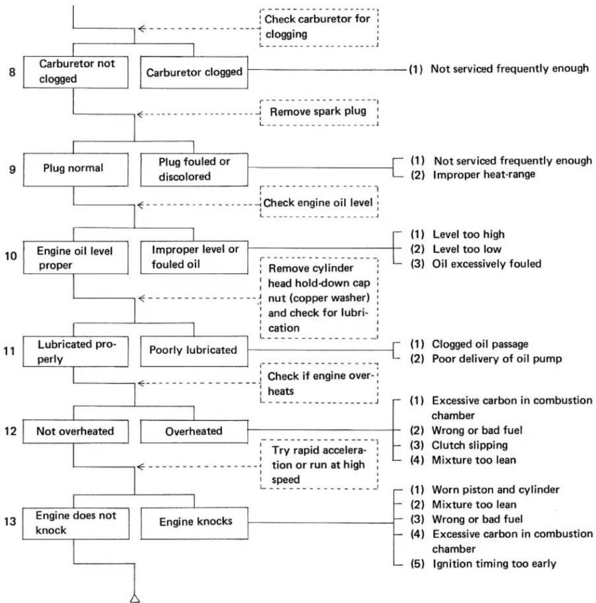
flowchart
graph TD
    A["Carburetor not clogged"] --> B["Check carburetor for clogging"]
    C["Carburetor clogged"] --> D["(1) Not serviced frequently enough"]
    E["Remove spark plug"] --> F["9) Plug normal"]
    F --> G["Plug fouled or discolored"]
    G --> H["Check engine oil level"]
    I["Engine oil level proper"] --> J["Improper level or fouled oil"]
    K["Lubricated properly"] --> L["Poorly lubricated"]
    M["Not overheated"] --> N["Overheated"]
    O["Engine does not knock"] --> P["Engine knocks"]
    Q["Check cylinder head hold-down cap nut (copper washer) and check for lubrication"] --> R["10) Level too high"]
    S["Remove spark plug"] --> T["11) Clogged oil passage"]
    U["Remove spark plug"] --> V["12) Poor delivery of oil pump"]
    W["Check if engine overheats"] --> X["13) Excessive carbon in combustion chamber"]
    Y["Try rapid acceleration or run at high speed"] --> Z["14) Worn piston and cylinder"]
    AA["Worn piston and cylinder"] --> AB["15) Mixture too lean"]
    AC["Worn piston and cylinder"] --> AD["16) Wrong or bad fuel"]
    AE["Worn piston and cylinder"] --> AF["17) Clutch slipping"]
    AG["Worn piston and cylinder"] --> AH["18) Mixture too lean"]
    AI["Worn piston and cylinder"] --> AJ["19) Worn piston and cylinder"]
    AK["Mixture too lean"] --> AL["20) Wrong or bad fuel"]
    AM["Mixture too lean"] --> AN["21) Excessive carbon in combustion chamber"]
    AO["Mixture too lean"] --> AP["22) Ignition timing too early"]
C. ROUGH IDLE OR POOR LOW SPEED PERFORMANCE (CARBURETOR IS CORRECTLY JETTED FOR LOCAL ALTITUDE.)
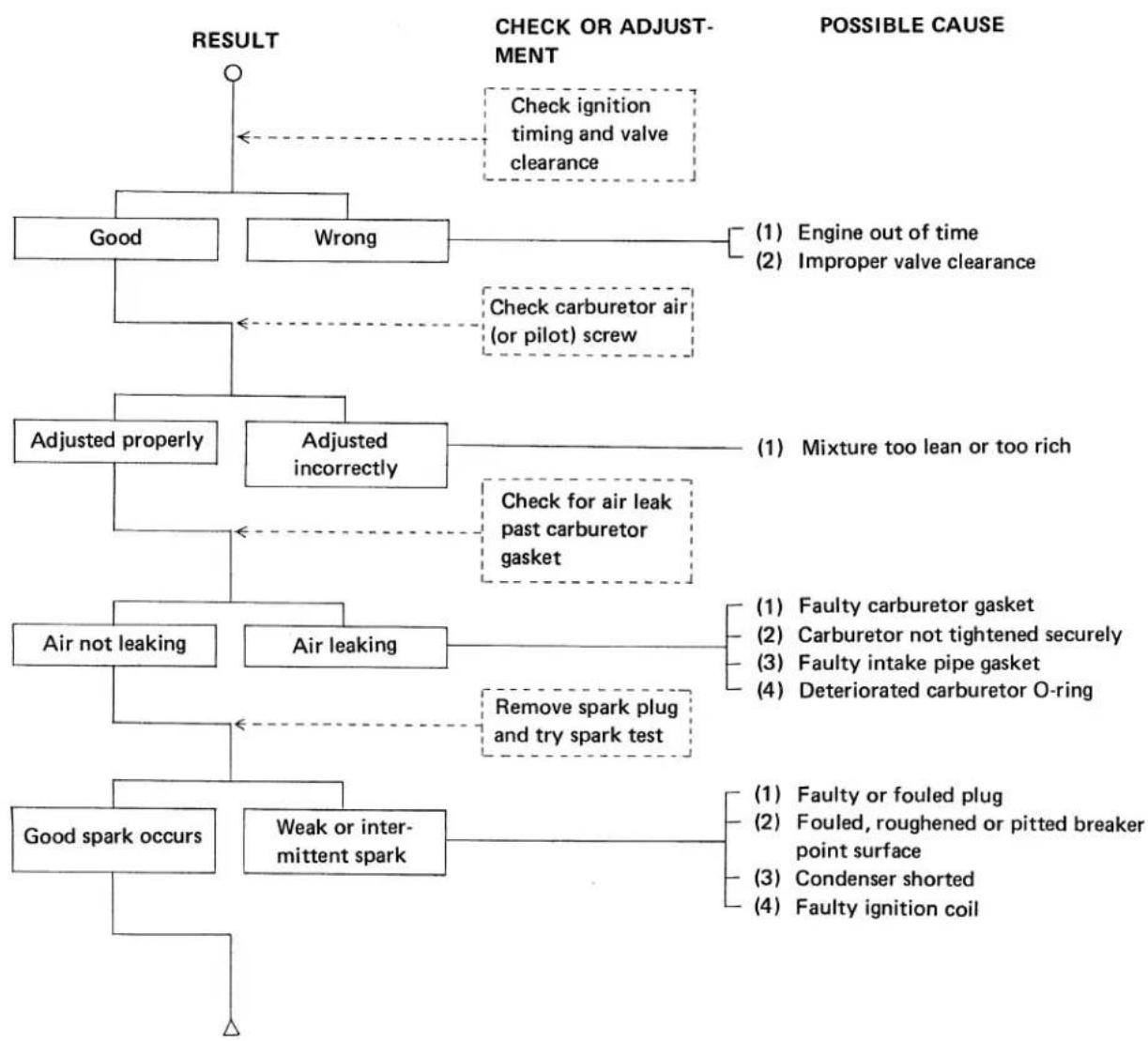
flowchart
graph TD
    A["RESULT"] --> B["Good"]
    A --> C["Wrong"]
    B --> D["Check ignition timing and valve clearance"]
    C --> E["Check carburetor air (or pilot) screw"]
    F["CHECK OR ADJUSTMENT"] --> G["Adjusted properly"]
    F --> H["Adjusted incorrectly"]
    F --> I["Air not leaking"]
    F --> J["Air leaking"]
    F --> K["Good spark occurs"]
    H --> L["Check for air leak past carburetor gasket"]
    H --> M["Remove spark plug and try spark test"]
    N["POSSIBLE CAUSE"] --> O["(1) Engine out of time\n(2) Improper valve clearance"]
    N --> P["(1) Mixture too lean or too rich"]
    Q["FAULTY CARBURETOR GASKET\n(2) CARBURETOR NOT TIGHTENED SECURELY\n(3) FAULTY INTAKE PIPE GASKET\n(4) DETERIORATED CARBURETOR O-RING"]
    R["FAULTY OR FOULED PLUG\n(2) FOULED, Roughened or pitted breaker point surface\n(3) CONDENSER SHORTED\n(4) FAULTY IGNITION COIL"]
D. ENGINE LACKS HIGH SPEED PERFORMANCE
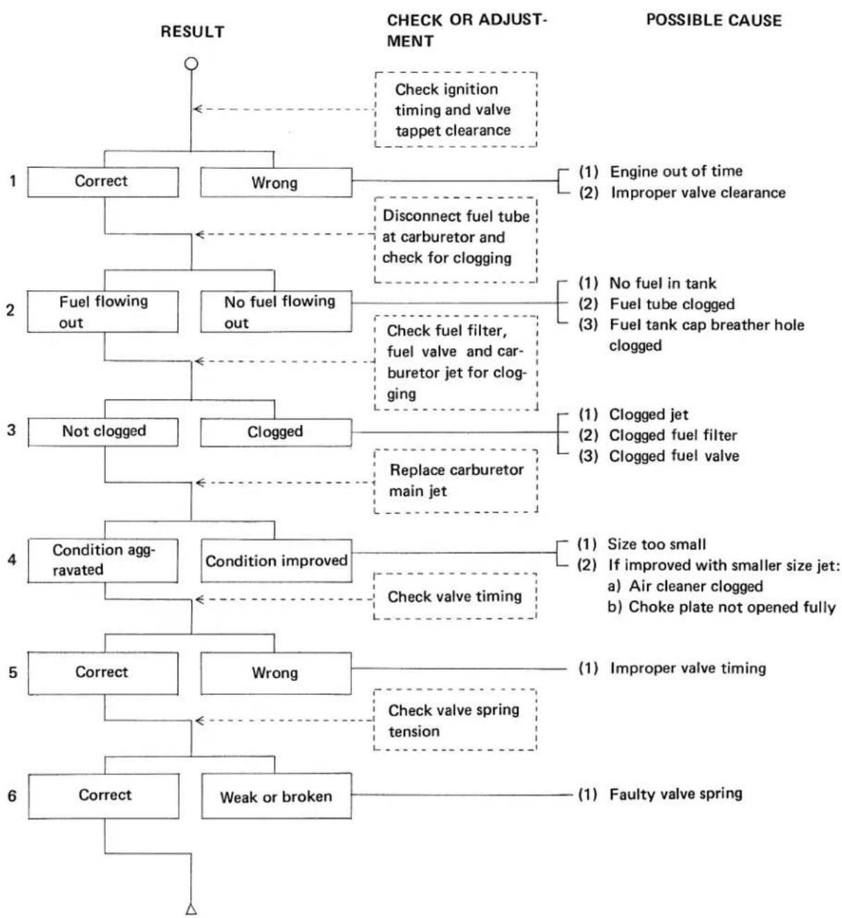
flowchart
graph TD
    A["1 Correct"] --> B["Check ignition timing and valve tappet clearance"]
    C["2 Fuel flowing out"] --> D["No fuel flowing out"]
    E["3 Not clogged"] --> F["Clogged"]
    G["4 Condition agg- ravated"] --> H["Condition improved"]
    I["5 Correct"] --> J["Wrong"]
    K["6 Correct"] --> L["Weak or broken"]

    M["1 Engine out of time\n2 Improper valve clearance"] --> N["(1) No fuel in tank\n2) Fuel tube clogged\n3) Fuel tank cap breather hole clogged"]
    O["1 Replace carburetor main jet"] --> P["(1) Clogged jet\n2) Clogged fuel filter\n3) Clogged fuel valve"]

    Q["1 Check valve timing"] --> R["(1) Size too small\n2) If improved with smaller size jet:\na) Air cleaner clogged\nb) Choke plate not opened fully"]
    S["1 Check valve spring tension"] --> T["(1) Improper valve timing"]
    U["1 Faulty valve spring"] --> V["(1) Faulty valve spring"]
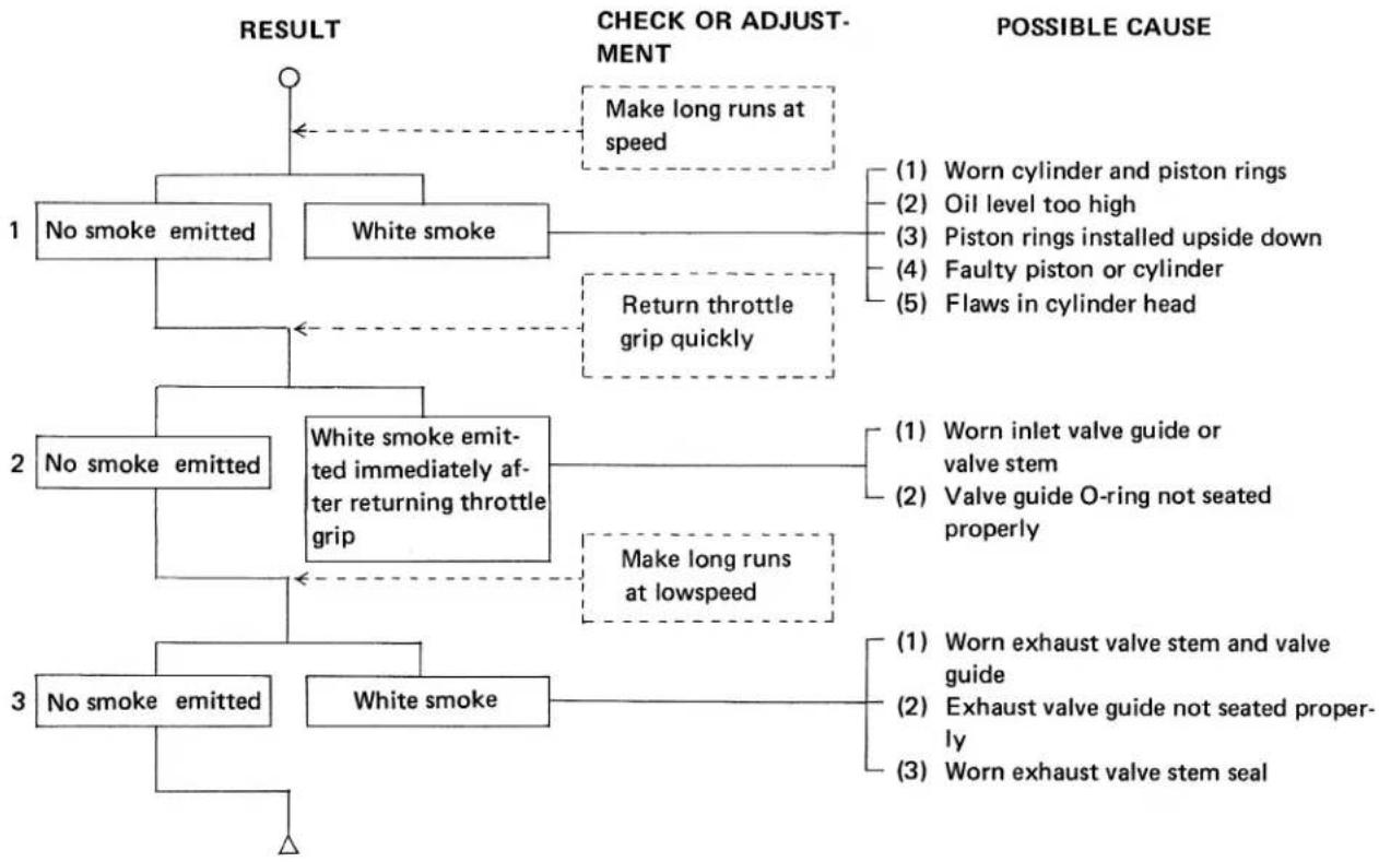
E. SMOKY EXHAUST
flowchart
graph TD
    A["RESULT"] --> B["1 No smoke emitted"]
    A --> C["2 No smoke emitted"]
    A --> D["3 No smoke emitted"]
    B --> E["Make long runs at speed"]
    C --> F["White smoke emitted immediately after returning throttle grip"]
    D --> G["White smoke"]
    E --> H["(1) Worn cylinder and piston rings"]
    E --> I["(2) Oil level too high"]
    E --> J["(3) Piston rings installed upside down"]
    E --> K["(4) Faulty piston or cylinder"]
    E --> L["(5) Flaws in cylinder head"]
    F --> M["(1) Worn inlet valve guide or valve stem"]
    F --> N["(2) Valve guide O-ring not seated properly"]
    G --> O["(1) Worn exhaust valve stem and valve guide"]
    G --> P["(2) Exhaust valve guide not seated properly"]
    G --> Q["(3) Worn exhaust valve stem seal"]
    C --> R["Return throttle grip quickly"]
    D --> S["Make long runs at lowspeed"]
    R --> H
    R --> I
    R --> J
    R --> K
    R --> L
    R --> M
    R --> N
    R --> O
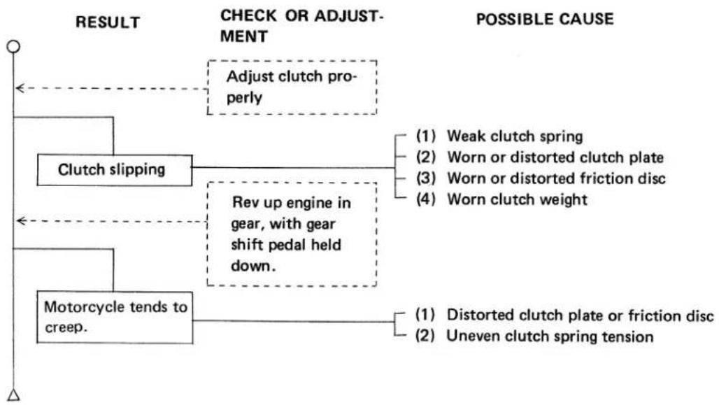
F. DEFECTIVE CLUTCH
flowchart
graph TD
    A["Start"] --> B["Clutch slipping"]
    B --> C["Rev up engine in gear, with gear shift pedal held down."]
    C --> D["Motorcycle tends to creep."]
    D --> E["Adjust clutch properly"]
    E --> F["(1) Weak clutch spring"]
    E --> G["(2) Worn or distorted clutch plate"]
    E --> H["(3) Worn or distorted friction disc"]
    E --> I["(4) Worn clutch weight"]
    D --> J["(1) Distorted clutch plate or friction disc"]
    D --> K["(2) Uneven clutch spring tension"]
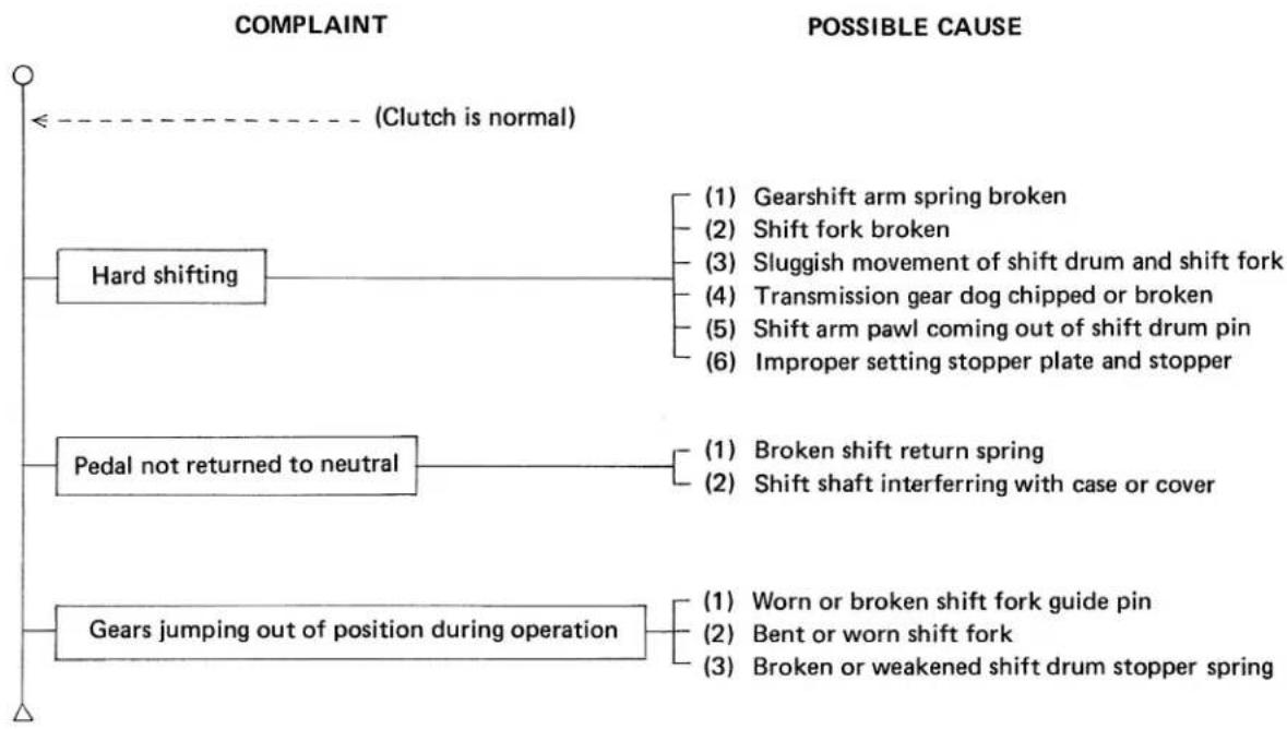
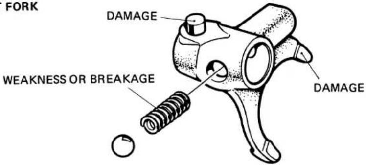
G. HARD SHIFTING
flowchart
graph TD
    A["Complaint"] --> B["Hard shifting"]
    B --> C["(1) Gearshift arm spring broken"]
    B --> D["(2) Shift fork broken"]
    B --> E["(3) Sluggish movement of shift drum and shift fork"]
    B --> F["(4) Transmission gear dog chipped or broken"]
    B --> G["(5) Shift arm pawl coming out of shift drum pin"]
    B --> H["(6) Improper setting stopper plate and stopper"]
    I["Possible CAUSE"] --> J["Pedal not returned to neutral"]
    J --> K["(1) Broken shift return spring"]
    J --> L["(2) Shift shaft interfering with case or cover"]
    M["Gears jumping out of position during operation"] --> N["(1) Worn or broken shift fork guide pin"]
    M --> O["(2) Bent or worn shift fork"]
    M --> P["(3) Broken or weakened shift drum stopper spring"]
    Q["Clutch is normal"] -.-> B
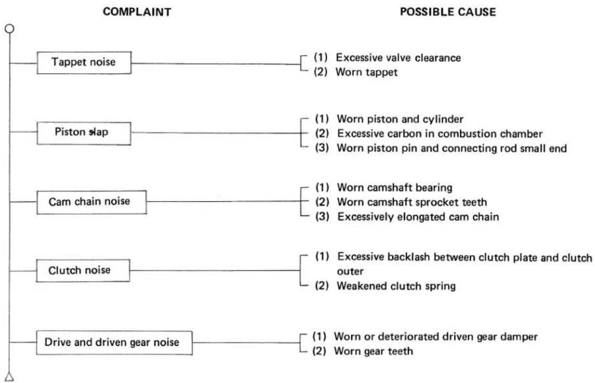
H. ENGINE NOISE
flowchart
graph TD
    A["COMPLAINT"] --> B["Tappet noise"]
    A --> C["Piston slap"]
    A --> D["Cam chain noise"]
    A --> E["Clutch noise"]
    A --> F["Drive and driven gear noise"]

    B --> G["(1) Excessive valve clearance\n(2) Worn tappet"]
    C --> H["(1) Worn piston and cylinder\n(2) Excessive carbon in combustion chamber\n(3) Worn piston pin and connecting rod small end"]
    D --> I["(1) Worn camshaft bearing\n(2) Worn camshaft sprocket teeth\n(3) Excessively elongated cam chain"]
    E --> J["(1) Excessive backlash between clutch plate and clutch outer\n(2) Weakened clutch spring"]
    F --> K["(1) Worn or deteriorated driven gear damper\n(2) Worn gear teeth"]
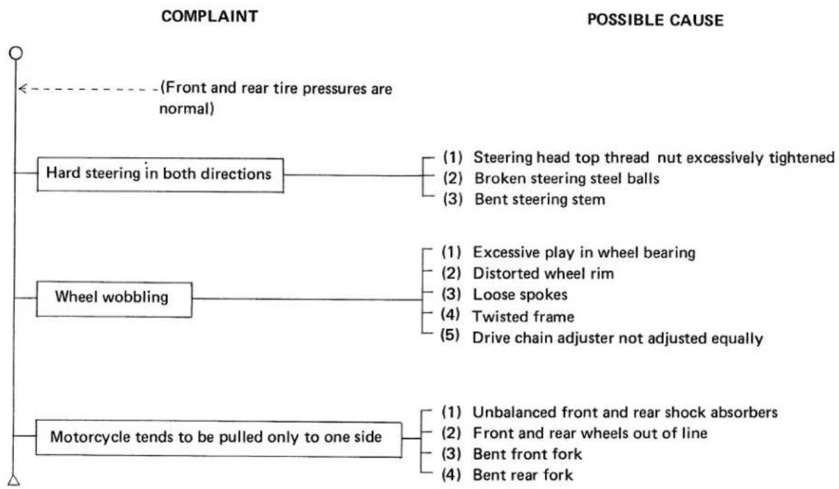
I. MOTORCYCLE PULLED TO ONE SIDE
flowchart
graph TD
    A["Complaint"] --> B["Hard steering in both directions"]
    A --> C["Wheel wobbling"]
    A --> D["Motorcycle tends to be pulled only to one side"]
    B --> E["(1) Steering head top thread nut excessively tightened"]
    B --> F["(2) Broken steering steel balls"]
    B --> G["(3) Bent steering stem"]
    C --> H["(1) Excessive play in wheel bearing"]
    C --> I["(2) Distorted wheel rim"]
    C --> J["(3) Loose spokes"]
    C --> K["(4) Twisted frame"]
    C --> L["(5) Drive chain adjuster not adjusted equally"]
    D --> M["(1) Unbalanced front and rear shock absorbers"]
    D --> N["(2) Front and rear wheels out of line"]
    D --> O["(3) Bent front fork"]
    D --> P["(4) Bent rear fork"]
    A -.-> Q["(Front and rear tire pressures are normal)"]
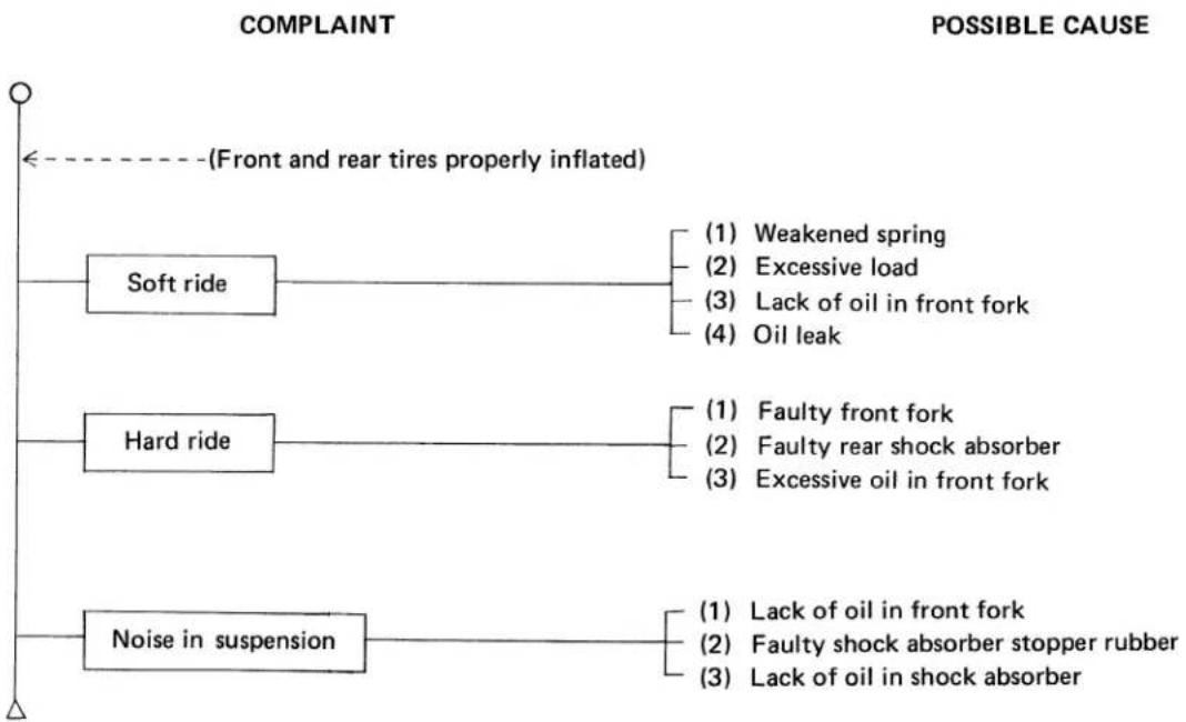
J. FAULTY FRONT AND REAR SHOCK ABSORBERS
flowchart
graph TD
    A["Complaint"] --> B["(Front and rear tires properly inflated)"]
    C["POSSIBLE CAUSE"] --> D["Soft ride"]
    C --> E["Hard ride"]
    C --> F["Noise in suspension"]
    D --> G["(1) Weakened spring"]
    D --> H["(2) Excessive load"]
    D --> I["(3) Lack of oil in front fork"]
    D --> J["(4) Oil leak"]
    E --> K["(1) Faulty front fork"]
    E --> L["(2) Faulty rear shock absorber"]
    E --> M["(3) Excessive oil in front fork"]
    F --> N["(1) Lack of oil in front fork"]
    F --> O["(2) Faulty shock absorber stopper rubber"]
    F --> P["(3) Lack of oil in shock absorber"]
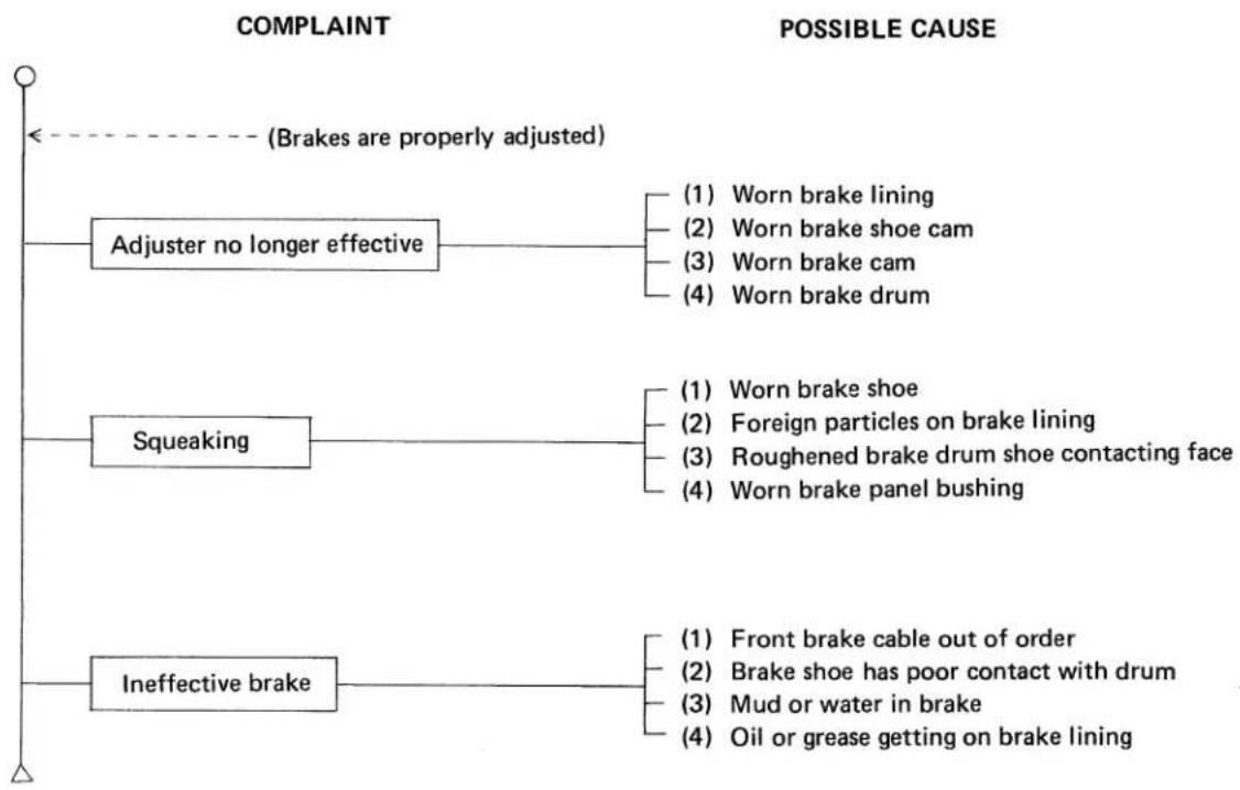
K. FAULTY BRAKE
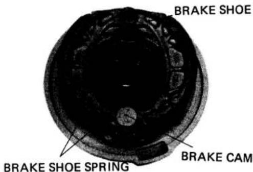
flowchart
graph TD
    A["COMPLAINT"] --> B["Adjuster no longer effective"]
    B --> C1["(1) Worn brake lining"]
    B --> C2["(2) Worn brake shoe cam"]
    B --> C3["(3) Worn brake cam"]
    B --> C4["(4) Worn brake drum"]
    A --> D["Squeaking"]
    D --> E1["(1) Worn brake shoe"]
    D --> E2["(2) Foreign particles on brake lining"]
    D --> E3["(3) Roughened brake drum shoe contacting face"]
    D --> E4["(4) Worn brake panel bushing"]
    A --> F["Ineffective brake"]
    F --> G1["(1) Front brake cable out of order"]
    F --> G2["(2) Brake shoe has poor contact with drum"]
    F --> G3["(3) Mud or water in brake"]
    F --> G4["(4) Oil or grease getting on brake lining"]
    H["(Brakes are properly adjusted)"] -.-> A
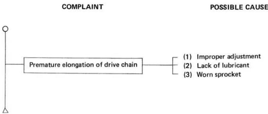
L. PREMATURE ELONGATION OF DRIVE CHAIN
flowchart
graph LR
    A["Complaint"] --> B["Premature elongation of drive chain"]
    C["Possible CAUSE"] --> D["(1) Improper adjustment"]
    C --> E["(2) Lack of lubricant"]
    C --> F["(3) Worn sprocket"]
1977 (K8) model
This maintenance schedule is based upon average riding conditions.
Machines subjected to severe use, or ridden in unusually dusty areas, require more frequent servicing.
| INITIAL SERVICE PERIOD | REGULAR SERVICE PERIOD Perform at every indicated month or mileage interval, whichever occurs first. | |||||
| ENGINE OIL | R | R | ||||
| CENTRIFUGAL OIL FILTER | C | |||||
| OIL FILTER SCREEN | C | |||||
| SPARK PLUG | I | |||||
| CONTACT BREAKER POINT | I | I | ||||
| IGNITION TIMING | I | I | ||||
| VALVE CLEARANCE | I | I | ||||
| CAM CHAIN TENSION | I | I | ||||
| POLYURETHANE FOAM AIR FILTER ELEMENT | (service more frequently\ if operated in dusty areas. C | |||||
| CARBURETOR | I | I | ||||
| THROTTLE OPERATION | I | I | ||||
| FUEL FILTER SCREEN | I | I | ||||
| FUEL LINES | C | |||||
| CLUTCH | I | I | ||||
| DRIVE CHAIN | ** I & L | I & L | ||||
| BRAKE SHOES | I | |||||
| BRAKE CONTROL LINKAGE | I | I | ||||
| WHEEL RIMS | I | I | ||||
| TIRES | I | I | ||||
| FRONT FORK OIL | *** R | |||||
| FRONT AND REAR SUSPENSION | I | I | ||||
| REAR FORK BUSHING | I | |||||
| STEERING HEAD BEARINGS | I | |||||
| SIDE STAND | I | |||||
| BATTERY | I | I | ||||
| LIGHTING EQUIPMENT | I | I | ||||
| NUTS, BOLTS (TIGHTEN) | I | I | ||||
I—Inspection, clean, adjust or replace if necessary. •R—Replace C—Clean L—Lubricate
**Initial service period 200 miles. *** Initial service period 1,500 miles.
1978 (K9) model
| FREQUENCYITEM | WHICHEVER →COMESFIRST↓ | ODOMETER READING [NOTE (2)] | |||
| 600 mi.(1000km) | 2400 mi.(4000km) | 4800 mi.(8000km) | 7200 mi.(12000km) | ||
| EVERY | |||||
| ENGINE OIL | YEAR | R | REPLACE EVERY1200mi. (2000km) | ||
| * ENGINE OIL FILTER ROTOR | C | ||||
| * ENGINE OIL FILTER SCREEN | C | ||||
| AIR CLEANER | NOTE (1) | C | C | C | |
| * FUEL LINES | I | I | I | ||
| SPARK PLUG | I | I | R | ||
| * VALVE CLEARANCE | I | I | I | I | |
| * CONTACT BREAKER POINTS | I | I | I | I | |
| * IGNITION TIMING | I | I | I | I | |
| * CAM CHAIN TENSION | A | A | A | A | |
| * THROTTLE OPERATION | I | I | I | I | |
| * CARBURETOR IDLE SPEED | I | I | I | I | |
| * CARBURETOR CHOKE | I | I | I | ||
| DRIVE CHAIN | NOTE (3) | INSPECT EVERY600mi. (1000 km) | |||
| BATTERY ELECTROLYTE | MONTH | I | I | I | I |
| BRAKE SHOE WEAR | I | I | I | ||
| BRAKE FREE PLAY | I | I | I | I | |
| * BRAKE LIGHT SWITCH | I | I | I | I | |
| * HEADLIGHT AIM | I | I | I | I | |
| SIDE STAND | I | I | I | ||
| CLUTCH | I | I | I | I | |
| * SUSPENSION | I | I | I | I | |
| * SPARK ARRESTOR | C | C | C | ||
| * NUTS, BOLTS, FASTENERS | I | I | I | I | |
| ** WHEELS/SPOKES | I | I | I | I | |
| ** STEERING HEAD BEARING | I | I | |||
I: INSPECTION, CLEAN, ADJUST, OR REPLACE IF NECESSARY.
C: CLEAN
R: REPLACE
A: ADJUST
** IN THE INTEREST OF SAFETY, WE RECOMMEND THESE ITEMS BE SERVICED ONLY BY AN AUTHORIZED HONDA DEALER.
* SHOULD BE SERVICE BY AN AUTHORIZED HONDA DEALER, UNLESS THE OWNER HAS PROPER TOOLS AND SERVICE DATA AND IS MECHANICALLY QUALIFIED.
NOTES (1) More frequent service may be required when riding in dusty areas.
(2) For higher odometer readings, repeat at the frequency interval established here.
(3) Initial service period 200 miles.
III INSPECTION/ADJUSTMENT
- CONTACT BREAKER POINT GAP
INSPECTION
- Remove the point and generator covers.
NOTE
Contact breaker point gap must be adjusted before the ignition timing adjustment is performed.
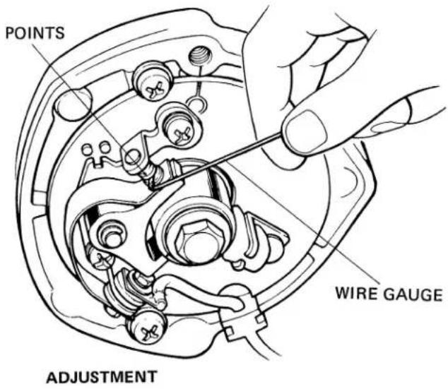
POINT GAP
0.3-0.4 mm (0.012-0.16 in.)
(1) Rotate the A.C. generator counterlockwise to find the position where the point gap is at maximum.
(2) Check the point gap with wire gauge.
POINT GAP
0.3-0.4 mm (0.012-0.016 in.)
- When adjustment is necessary, observe the following:
natural_image
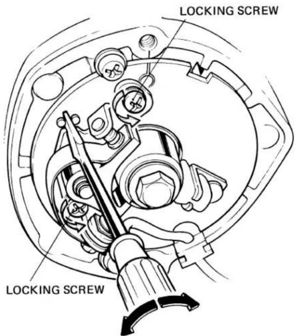
Technical diagram of a mechanical component with no visible text or symbols(1) Rotate the A. C. generator rotor counterclockwise to find the position where the point gap is at maximum.
(2) Loosen the contact breaker plate locking screws and move the contact breaker plate to achieve correct gap.
(3) When properly adjusted, retighten the locking screws.
NOTE
Do not allow the plate to move when tightening the locking screws.
(4) Rotate the A.C. generator rotor several times and recheck the breaker point gap. If the gap is incorrect, repeat the steps (1) thru (4) above.
- IGNITION TIMING
Do not perform this operation until point gap has been adjusted.
Static test (with a use of test lamp)
CAUTION
Use caution when adjusting the timing not to touch the points with a screwdriver.
Dynamic test (with a use of stroboscopic light)
Make the connections as described in the booklet furnished with the service tester.
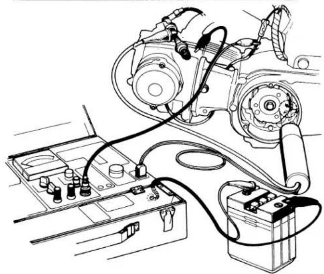
natural_image
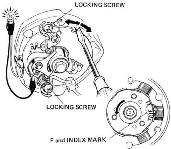
Technical line drawing of an automotive diagnostic setup with battery, test case, and motor components (no text or labels)(1) Remove the point and generator covers.
(2) Turn on the ignition switch.
(3) Rotate the A.C. generator rotor slowly in the counterclockwise direction.
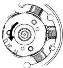
(4) Align the "F" mark on the rotor with the index mark on the stator on compression stroke.
(5) The contact breaker points should just start to open when both marks align (the timing light should come on). If the timing of the breaker point opening is incorrect, adjustment is made by loosening the base plate locking screws and carefully rotating the base plate until the light comes on.
TO ADVANCE TIMING....Rotate the base plate clockwise. TO RETARD TIMING.....Rotate the base plate counterclockwise.
(6) Retighten the base plate locking screws securely, exercising care not to allow the base plate to move.
(7) Rotate the A.C. generator rotor several times and recheck the timing. If the moment of point opening is incorrect, repeat the steps (3) thru (7) above.
Idling: 1300 rpm
"F" MARK ALIGNED WITH
INDEX MARK
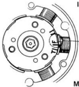
natural_image
Technical diagram of a mechanical component with labeled parts (I, M, TIF), no readable text or symbols beyond labelsF and INDEX MARK
Max. Advance: 2600 rpm
"ADVANCE" MARKS ALIGNED WITH INDEX MARK
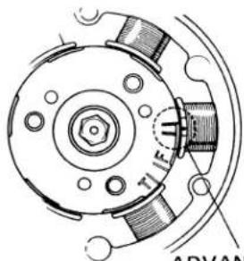
ADVANCE MARKS and INDEX MARK
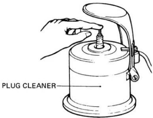
- SPARK PLUG
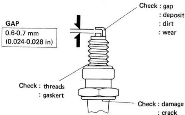
To install, first thighten finger tight, then tighten with a spark plug wrench to compress the washer.
- VALVE CLEARANCE
Valve tappet clearance inspection and adjustment should be performed while the engine is cold.
(1) Remove the tappet hole caps and generator cover.
VALVE CLEARANCE (IN, EX)
0.05 ± 0.02 mm (0.002 ± 0.0008 in.)
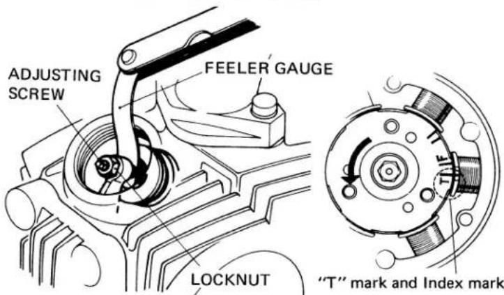
(2) Rotate the A.C. generator rotor in the counterclockwise direction and align the "T" mark on the rotor with the index mark on the stator.
Perform this operation with the cylinder at T.D.C. (top-dead-center) of the compression stroke. In this position, the intake and exhaust valves should be fully closed.
To clean use a plug cleaner or steel wire.
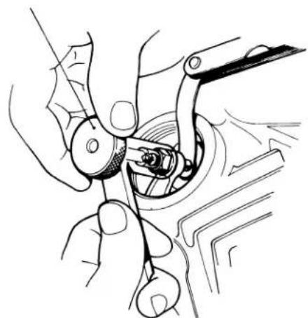
(3) Check the clearance of both valves by inserting a feeler gauge between the tappet adjusting screw and the valve stem.
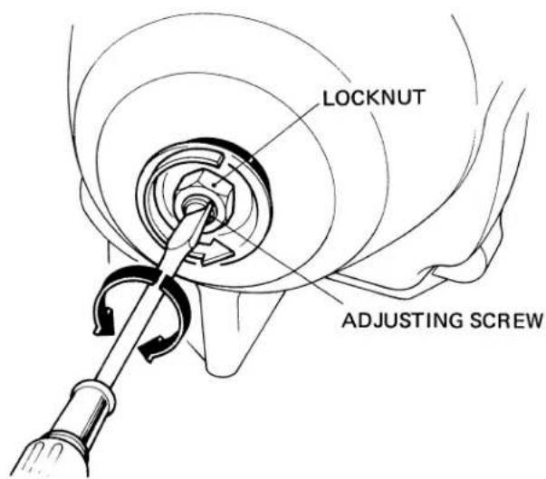
(4) Adjustment is made by loosening the tappet screw lock nut and turning the adjusting screw until there is a slight drag on the feeler gauge.
TAPPET ADJUSTING WRENCH
NO. 07908-0010000
natural_image
Line drawing of hands using a tool to adjust or install a mechanical component (no text or symbols visible)Hold the adjusting screw while the lock nut is being tightened.
(5) Rotate the A.C. generator rotor several times and re-check the clearance with the feeler gauge.
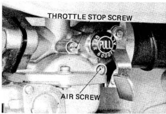
• IDLE SPEED AND MIXTURE
Perform this operation while the engine is hot.
- THROTTLE CABLE
(1) Minor adjustment is made with the upper adjuster.
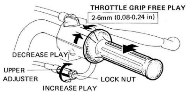
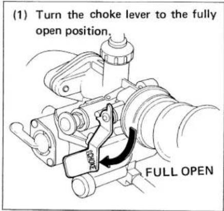
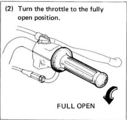
(1) With engine running at operating temperature, turn the throttle stop screw counterclockwise to obtain the lowest stable idle speed possible.
(2) Turn the air screw (pilot screw on 1978 (K9 model) in either direction to find the setting that produces the highest idle speed obtainable without readjusting the throttle stop screw.
NOTE: If air/pilot screw adjustment causes idle speed to increase beyond 1300 rpm, turn the throttle stop screw farther counterclockwise to lower the idle speed and repeat step 2.
(3) After air/pilot screw adjustment has been completed, adjust the throttle stop screw to achieve the specified idle speed of 1300 rpm. Open and close the throttle a few times to verify proper throttle response, prompt return to idle, and stable idle speed.
IDLE SPEED 1300 rpm
| STANDARD AIR SCREW OPENING | 1 turn1977(k8) model |
| STANDARD PILOT SCREW OPENING | 114 turn1978(k9)model |
(2) Major adjustment is made with the lower adjuster.
- If adjustment is to be made with the lower adjuster, loosen the upper adjuster.
• Make sure the rubber cap is tightened securely.
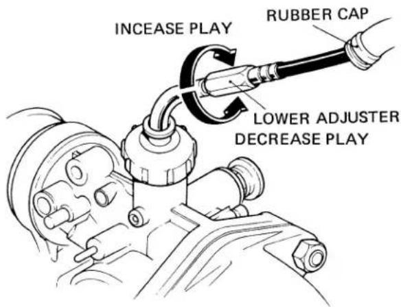
Replace the throttle cable if both adjustments are no longer effective.
• CAM CHAIN TENSIONER
Perform this adjustment while the engine is idling.
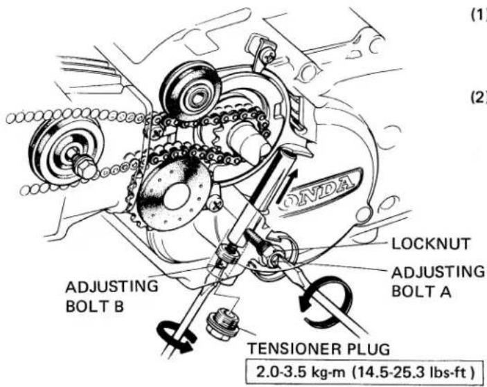
(1) Loosen the lock nut and loosen the adjusting bolt A approximately 112 turn. At this, the chain should be automatically adjusted by force of the tensioner springs.
(2) If the chain is still noisy, remove the tensioner plug and screw in the adjusting bolt B gradually until the cam chain is no longer noisy.
After completing adjustment tighten the adjusting bolt A, lock nut and plug.
• AIR CLEANER CLEANING
WARNING
Gasoline or low flash point solvents are highly flammable and must not be used to clean the air cleaner element.
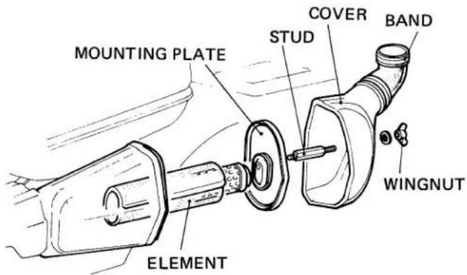
(1) Remove the wing nut and loosen the band, and remove the cover and band.
(2) Remove the stud and mounting plate.
(3) Pull out the air cleaner element.
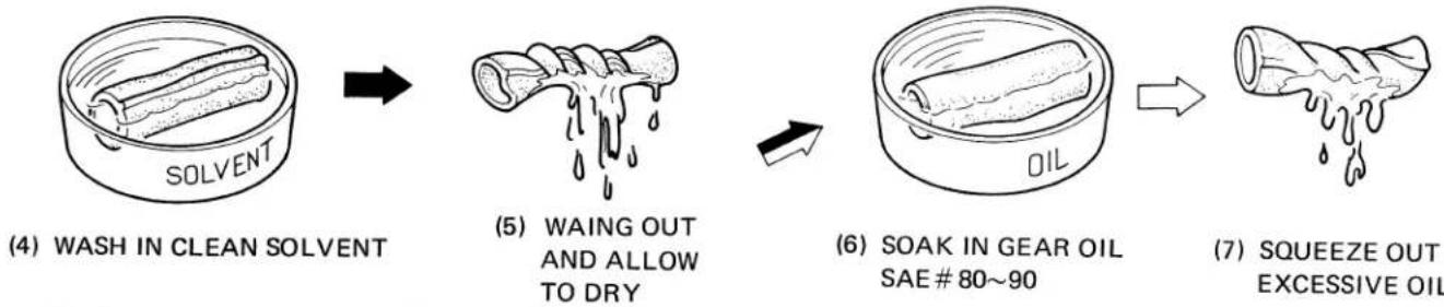
flowchart
graph LR
    A["(4) WASH IN CLEAN SOLVENT"] --> B["(5) WAING OUT AND ALLOW TO DRY"]
    B --> C["(6) SOAK IN GEAR OIL SAE # 80~90"]
    C --> D["(7) SQUEEZE OUT EXCESSIVE OIL"]
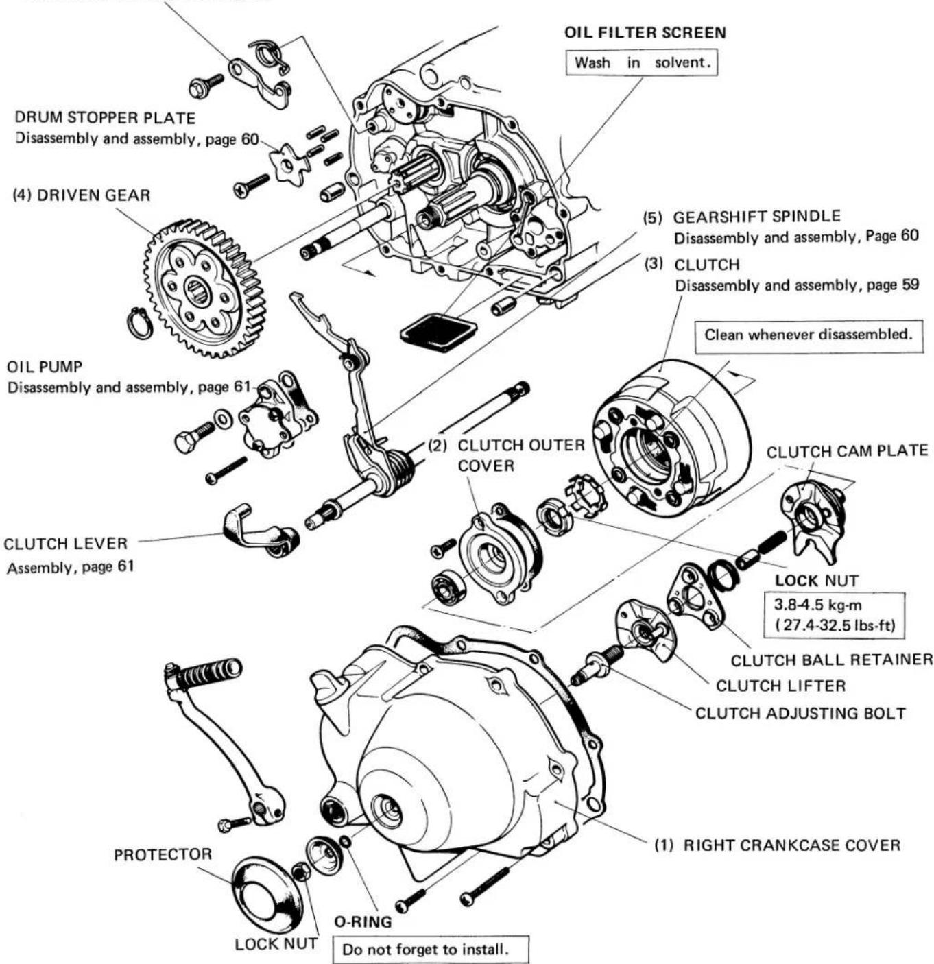
• OIL FILTER CLEANING
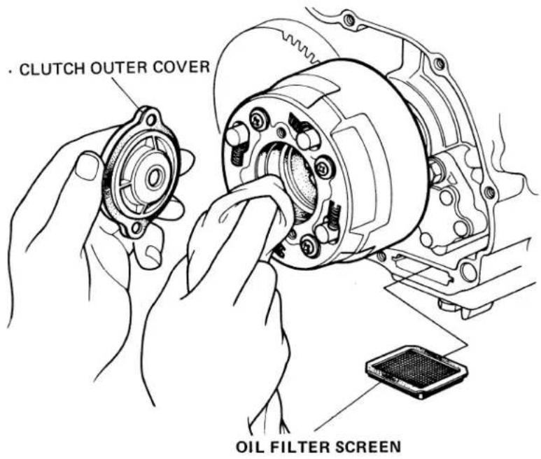
(1) Drain engine oil.
(2) Remove the kick pedal and right crankcase cover.
(3) Remove the clutch outer cover and clean the filter chamber with lintfree cloth.
(4) To clean the oil filter screen, pull the screen out, and wash in clean solvent.
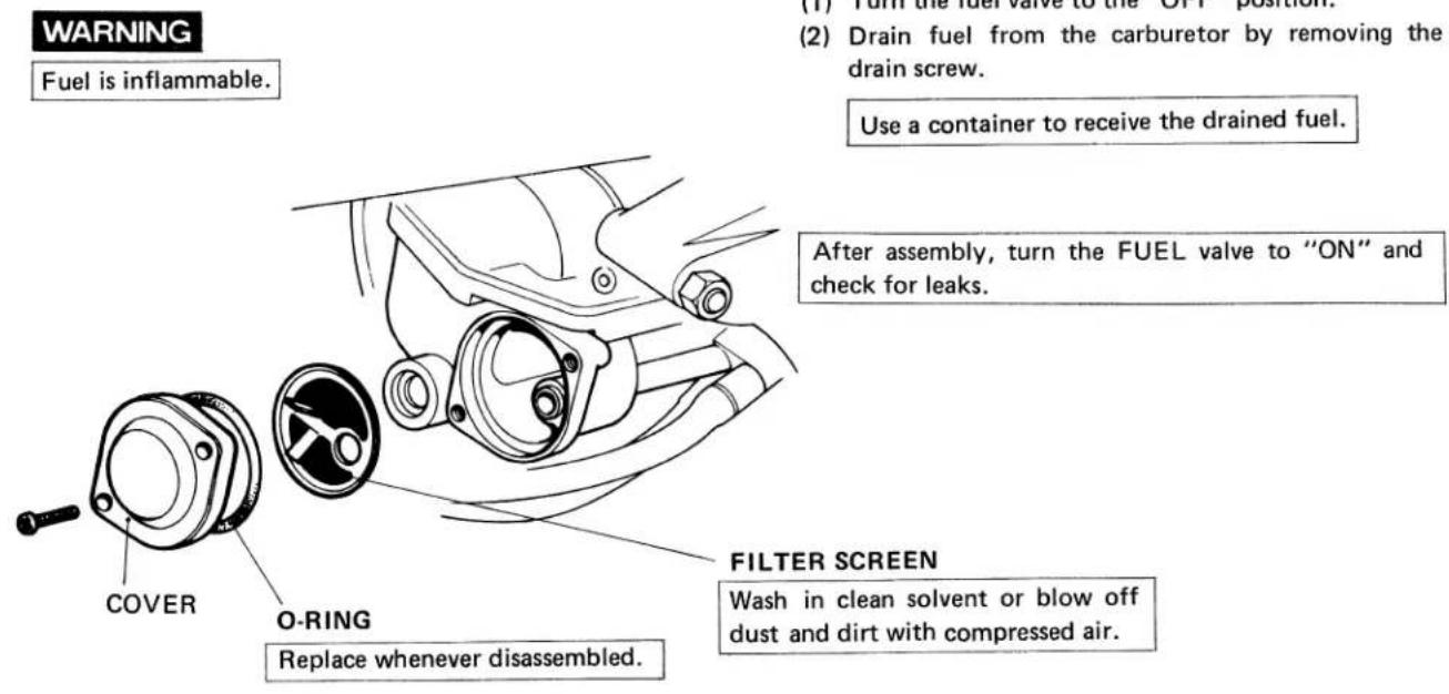
• FUEL FILTER CLEANING
- ENGINE OIL
- Oil Level
(1) Operate engine for approximately a few minutes.
(2) Stop the engine, place the motorcycle on the center stand.
(3) Check the oil level with the filler cap dipstick
(4) To check the oil level, insert the dipstick, but do not screw in. Oil level must be between the upper and lower level marks.
(5) If the level is low, fill with recommended grade oil to the upper level mark on the gauge. Drain the oil and pour fresh oil if the oil is contaminated.
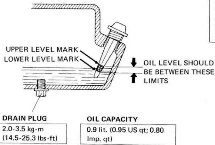
- Oil Change
(1) Remove the drain plug to drain oil from the engine.
(2) Operate the kick starter pedal several times to drain all residual oil remaining in the crankcase.
(3) Reinstall the drain plug and refill with fresh oil to the upper level mark.
(4) Recheck the oil level.
OIL SPECIFICATION
Use Honda 4-stroke oil or equivalent.
API service classification - SE
All temp. - SAE 10 - 40
Above 15°C (59°F) SAE 30
0^(32^)-15^(59^) SAE 20 or SAE 20W
Below 0^ C ( 32^ F) SAE 10W
- CLUTCH
(1) The clutch is adjusted with the engine off. Remove the cover protector and loosen the adjuster lock nut.
(2) Turn the clutch adjusting screw clockwise about one turn; do not turn excessively.
(3) Next, slowly turn the screw counterclockwise and stop when the screw meets resistance.
(4) From this point, turn the adjusting screw clockwise 1/8 to 1/4 turn, and tighten the lock nut.
- Don't turn out the adjusting screw more than necessary.
- Hold the adjusting screw while tightening the lock nut.
(5) Check the operation of the clutch.
NOTE
- After the adjustment has been made, check to see that the engine starts easily and that the clutch is not slipping and is properly disengaging.
• Make sure that the engine will not stall or lunge when the gears are shifted.
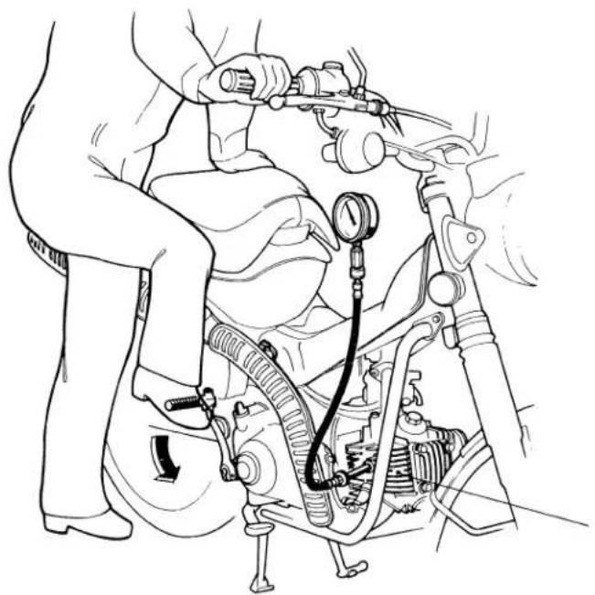
• CYLINDER COMPRESSION
Engine should be warmed up
Pressure
10-12 kg/cm² (142-170 psi)
natural_image
Line drawing of a car engine assembly with hoses and sensors (no text or symbols)■ Low compression is due to the following causes:
- Leaking valve
• Faulty piston rings, piston and cylinder - Blown cylinder head gasket
• Insufficient valve clearance.
■ Unusually high compression is due to excessive carbon deposits on the combustion chamber or on the piston head.
- Engine must be disassembled for complete inspection or repair in these cases.
NOTE
To avoid leaks, screw gauge adapter into spark plug hole securely.
(3) Kich several times
Kick with rapid, full strokes until gauge needle reaches the highest reading.
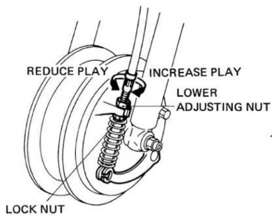
- FRONT BRAKE
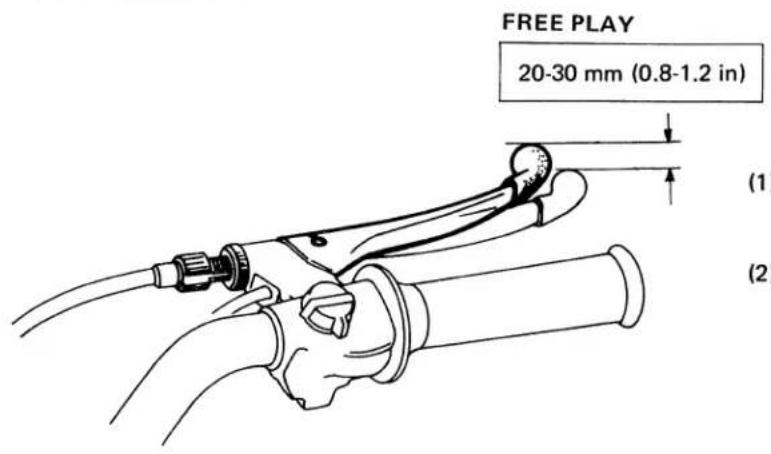
(1) Perform major free play adjustments at the front wheel. Loosen the lock nut and turn the adjusting nut to increase or decrease brake lever free play.
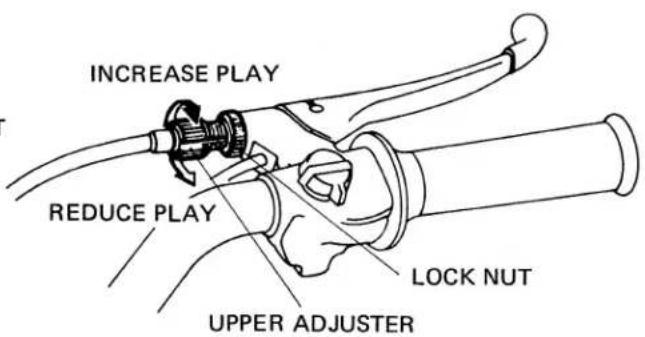
(2) Perform minor free play adjustments at the handlebar. Loosen the lock nut and turn the adjuster to increase or decrease brake lever free play.
natural_image
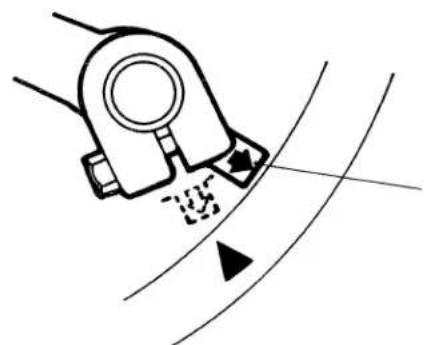
Diagram of a mechanical device emitting particles onto a curved surface with intersecting lines (no text or symbols)WEAR INDICATOR
If the “↑” mark on the indicator aligns with the “▲” mark on the brake panel at full application of the brake, replace the brake shoes.
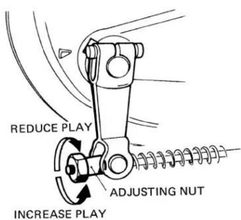
- REAR BRAKE
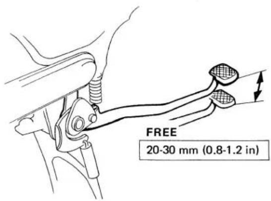
Adjust rear brake pedal free play by turning the adjusting nut which is located at the rear wheel.
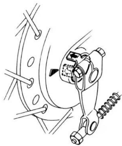
natural_image
Mechanical assembly diagram showing a brake caliper and spring mechanism (no text or labels)WEAR INDICATOR
If the “↑” mark on the indicator aligns with the “▲” mark on the brake panel at full application of brake, replace the brake shoes.
- REAR BRAKE STOPLIGHT SWITCH
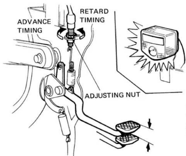
Turn the adjusting nut as required.
The stoplight should come on when the brake pedal is depressed to the point where the rear brake just starts to take hold.
- DRIVE CHAIN
• INSPECTION
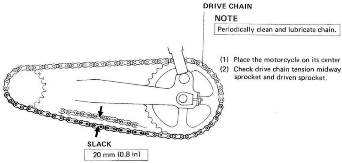
ADJUSTMENT
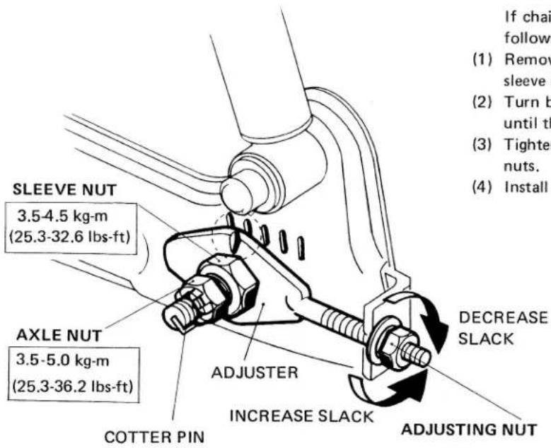
If chain slack is found to exceed the limit, adjust as follows:
(1) Remove the cotter pin, loosen the axle nut and sleeve nut.
(2) Turn both adjusting nuts an equal number of turns until the drive chain tension is obtained.
(3) Tighten the sleeve nut, axle nut and both adjusting nuts.
(4) Install the cotter pin and spread the ends.
- BATTERY
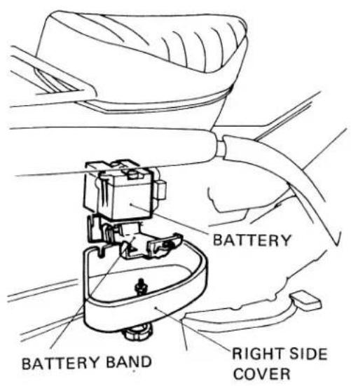
(1) Remove the right side cover.
(2) Remove the battery band bolt and pull the battery out.
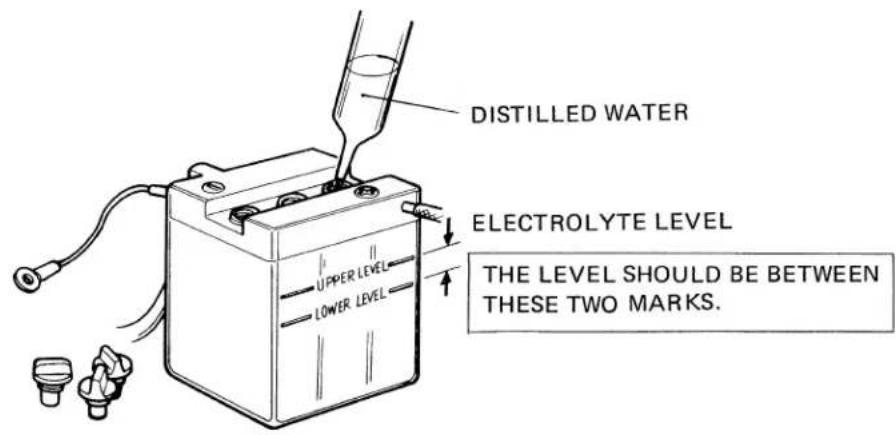
(3) Check electrolyte level. The level should be between the upper and lower level marks.
(4) If it is not, add distilled water to the upper level.
NOTE
- Replace the battery if sulfation is evident.
- Replace the battery if there is excessive sediment on the bottom of the cells.
WARNING
- The battery contains sulfuric acid and should be handled with care.
- Do not overfill beyond the UPPER level.
- Avoid contact with skin, eyes or clothing. Flush with water and get prompt medical attention when in contact with skin or eyes.
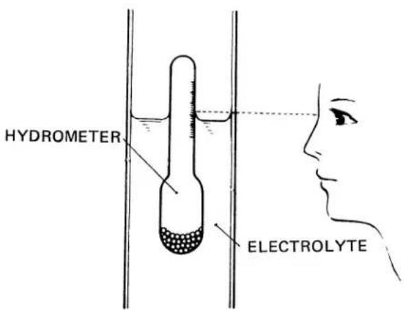
ELECTROLYTE SPECIFIC GRAVITY
1.260-1.280 [20°C (68°F)]
1.250 or below: Undercharged
1.220 or below: Recharge the battery
For relationship between electrolyte temperature and specific gravity, see page 102
• FRONT FORK OIL CHANGE
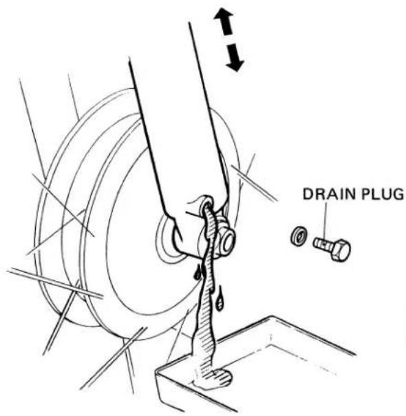
(1) Remove the front fork drain plugs and fork filler plugs.
(2) Drain the oil by pumping the fork up and down.
(3) Replace the drain plugs after draining.
- Drain and refill both fork legs at the same time.
FILLER PLUG
3.5-4.5 kg-m (25.3-32.6 lbs-ft)
ATF
To fill dry fork assembly 130-140 cc (4.4-4.7 oz.) To refill after draining 120-130 cc (4.1-4.4 oz.)
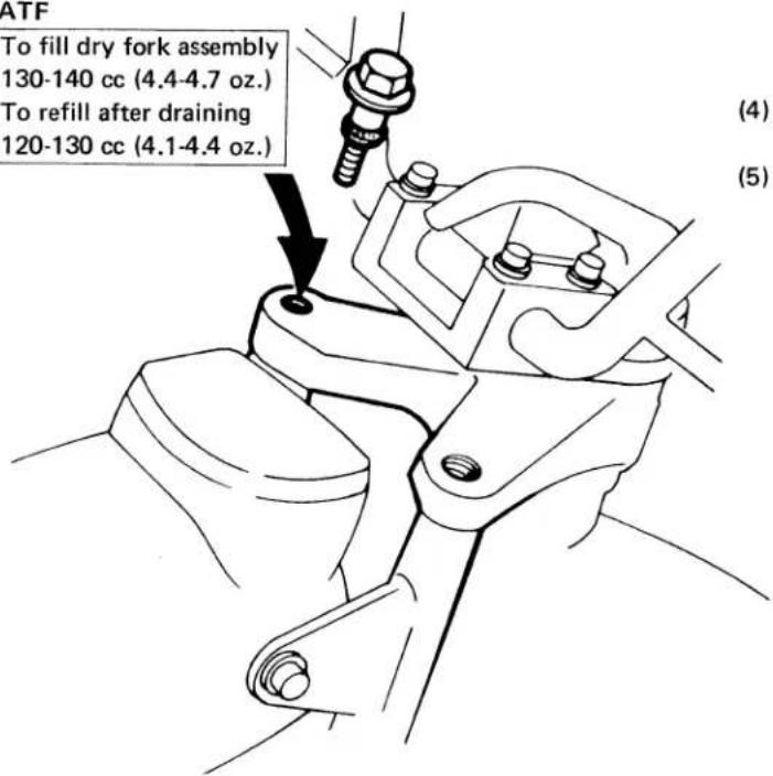
(4) Pour ATF (automatic transmission fluid) into each fork leg.
(5) Securely tighten the filler plugs.
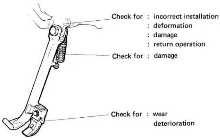
- SIDE STAND
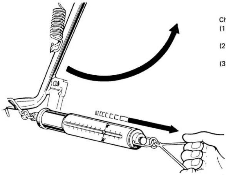
Check the side stand for proper return operation.
(1) With the side stand lowered, raise the stand off the ground using the center stand.
(2) Attach a spring scale to the lower end of the stand and measure the force required to raise the stand.
(3) The stand condition is correct if the measurement falls within 2-3kg (4.4-6.6 lbs.).
If excessive force is required to raise the stand, this may be due to neglected lubrication over tightened pivot bolt, worn side stand bar or bracket or otherwise excessive tension.
natural_image
Technical line drawing of a mechanical clamp or bracket with a circular symbol below (no text or labels)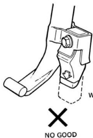
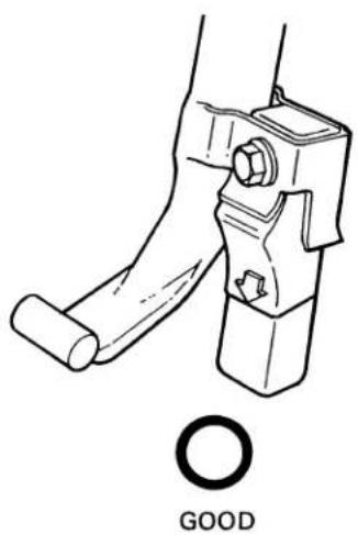
Check the rubber block for deterioration or wear. When the rubber block wear is so excessive that it is worn down to the wear line, replace it with a new one.
WEAR LIMIT LINE
- Shift the transmission into neutral position.
- Set the motorcycle on the center stand.
- Turn the ignition switch to the OFF position.
Perform the following with care while/after installing the engine.
- Rear brake adjustment .... page 31
- Stop light Switch adjustment .... page 31
- Drive chain adjustment .... page 32
• Installation direction of carburetor top .... page 78 - Installation direction of drive chain ..... page 90
- Connection of fuel tubes.... page 96
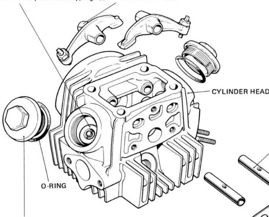
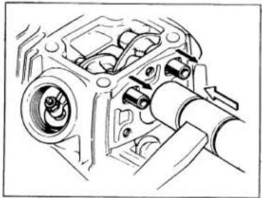
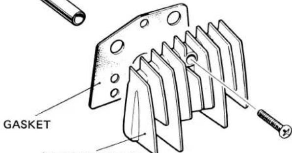
- Remove the intake pipe, exhaust muffler and generator cover.
a. DISASSEMBLY/ASSEMBLY
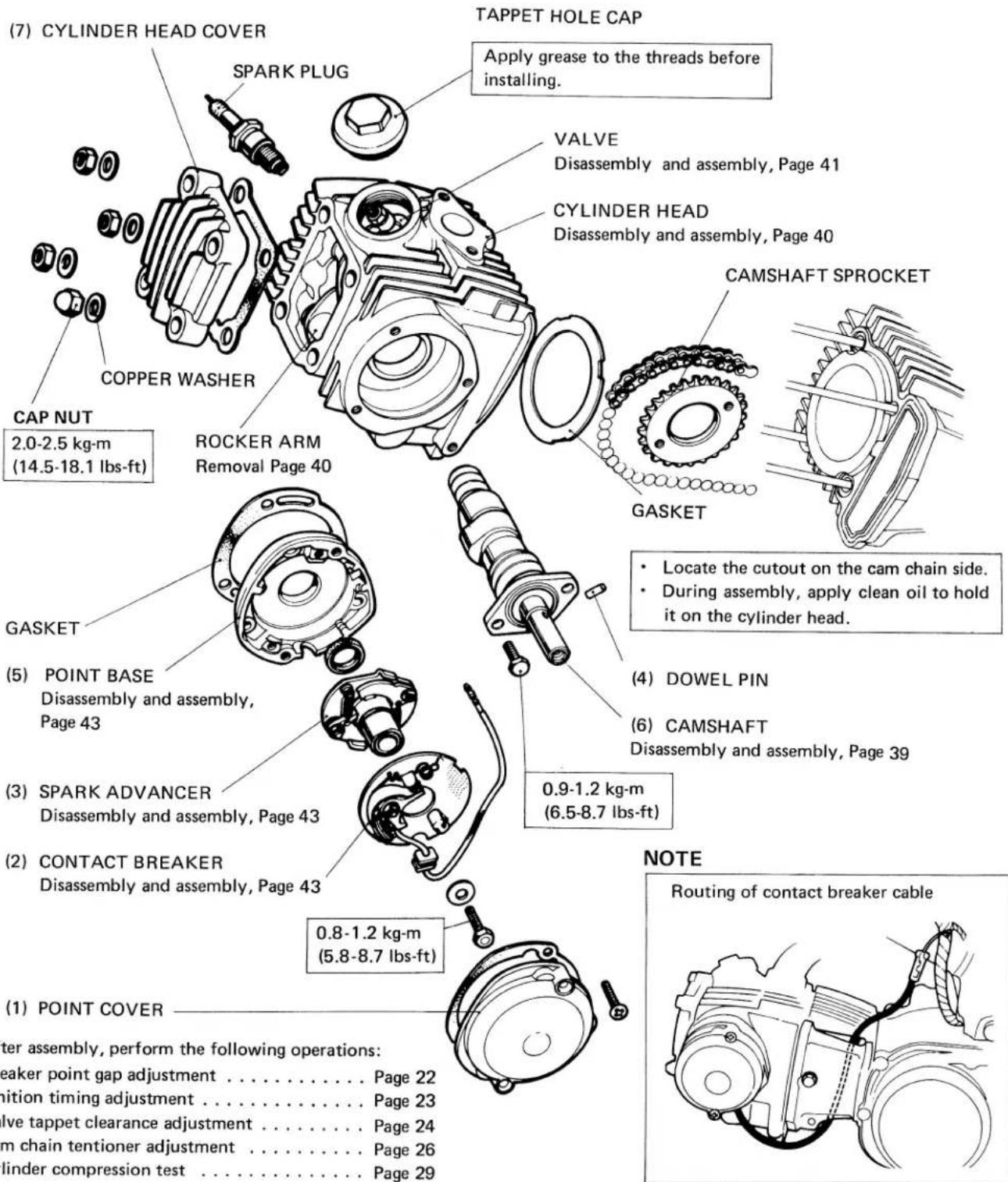
• CAMSHAFT DISASSEMBLY
natural_image
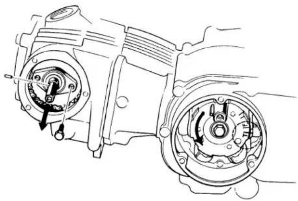
Technical line drawing of a mechanical assembly with two gears and a shaft (no text or symbols)(1) Rotate the A.C. generator rotor counterclockwise and align the "T" mark on the rotor with the index mark on the stator at compression stroke.
(2) Remove the two 6 mm bolts from the camshaft.
(3) Pull out the camshaft.
NOTE
The cylinder head hold-down nuts should be tight while the camshaft is removed. Failure to do so will result in difficulty in removing the shaft due to increased tension on the cam chain.
- CAMSHAFT ASSEMBLY (VALVE TIMING ADJUSTMENT)
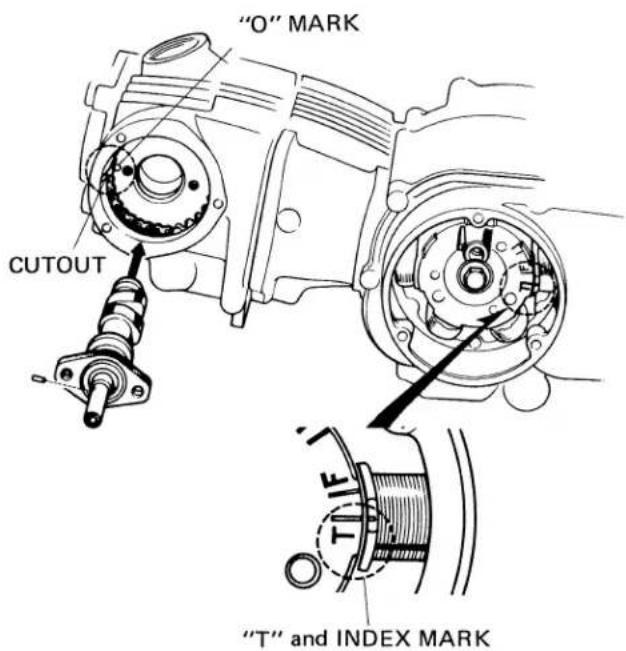
(1) Rotate the A.C. generator rotor and align the "T" mark on the rotor with the index mark (at T.D.C.).
(2) Place the cam chain on the camshaft sprocket.
(3) Install the cylinder head.
NOTE
Make sure that the "O" mark on the sprocket is aligned with the cutout in the cylinder head.
(4) Install the cylinder head cover and tighten to the specified torque.
(5) Install the camshaft and the two 6 mm bolts with the dowel hole in the shaft facing toward the "O" mark.
- ROCKER ARM DISASSEMBLY/ASSEMBLY
VALVE
Disassembly and assembly, Page 41
(4) ROCKER ARM
natural_image
Technical line drawing of a mechanical component with no visible text or symbols(2) ROCKER ARM SHAFT
(3) TAPPET HOLE CAP
Coat the threads with grease before installation.
(1) R-SIDE COVER
- VALVE DISASSEMBLY/ASSEMBLY
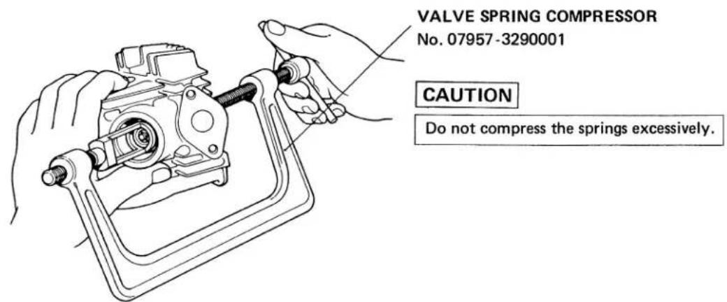
VALVE COTTER
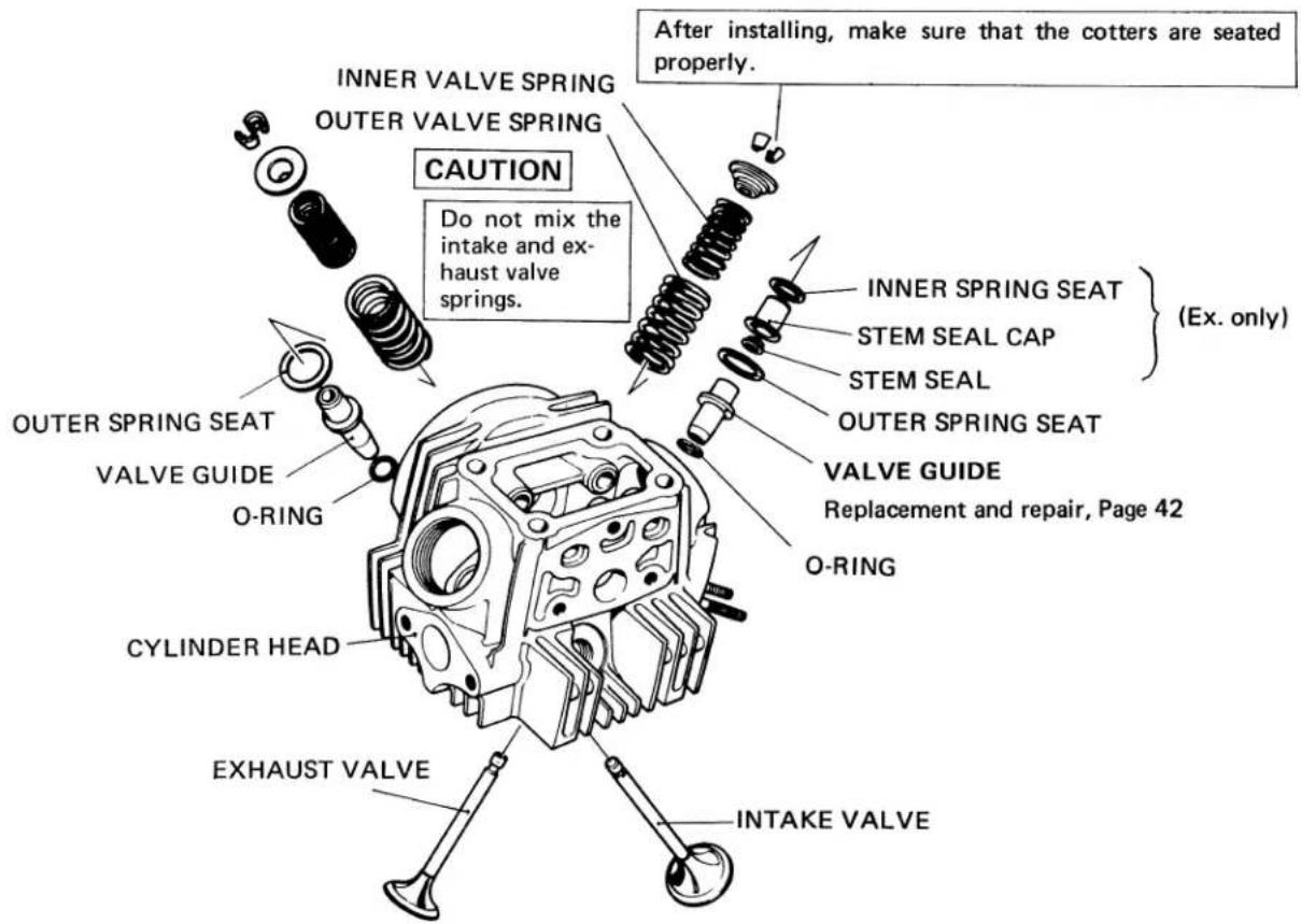
When installing a new valve, check the contact between the valve face and valve seat and correct if necessary.
• VALVE GUIDE REPLACEMENT/REPAIR
It is recommended to replace the valves when the valve guides are renewed.
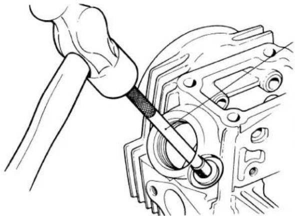
• DRIVING OUT VALVE GUIDE
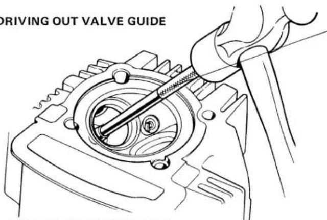
TOOL
VALVE GUIDE DRIVER
No. 07942-3290100
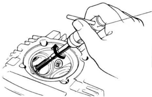
• DRIVING IN VALVE GUIDE
natural_image
Line drawing of a hand using a tool to adjust or install a mechanical component (no text or symbols present)VALVE GUIDE DRIVER
INTAKE: No.07942-1180100
EXHAUST: No. 07942-3290100
After a new valve guide has been driven to the proper depth, check that it is not damaged.
- REAMING VALVE GUIDE
After installing a new guide, ream the guide to size using the Valve Guide Reamer.
VALVE GUIDE I.D.
IN/EX 5.475-5.485 mm (0.2157-0.2161 in.)
natural_image
Hand using a tool to adjust or install a mechanical component (no text or symbols visible)VALVE GUIDE REAMER
No. 07984-0980000
• Always rotate the reamer in the clockwise direction when reaming the guide.
• To keep the reamed surface from being scratched, rotate the reamer clockwise as it is pulled out.
- Remove all traces of metal particles from the guide with solvent.
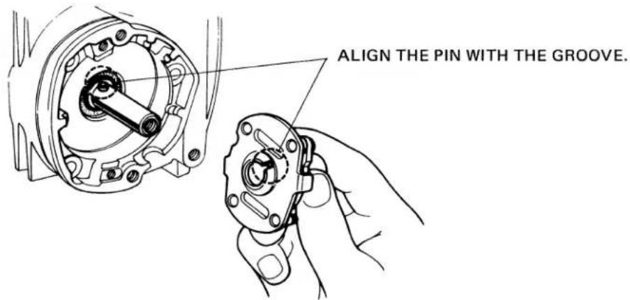
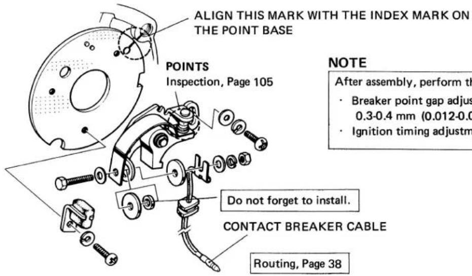
- CONTACT BREAKER POINT BASE ASSEMBLY
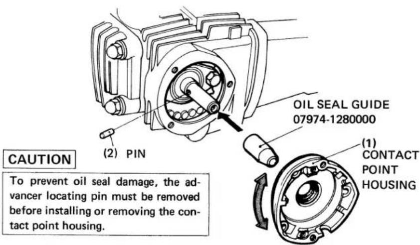
Place the oil seal guide over the camshaft end. Spread a thin film of oil on the guide to ease seal installation. Carefully install the contact point housing and oil seal. Remove the oil seal guide and check that the oil seal is properly seated. Insert the advancer locating pin.
• SPARK ADVANCER ASSEMBLY
- CONTACT BREAKER DISASSEMBLY/ASSEMBLY
b. INSPECTION
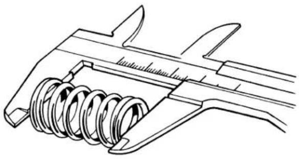
- VALVE SEAT WIDTH
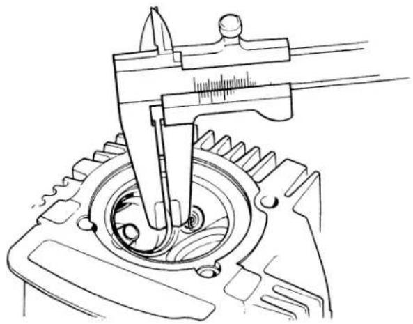
natural_image
Technical line drawing of a mechanical gear assembly with caliper (no text or symbols)Take measurements at several points.
| Standard | Service Limit | |
| IN/EX | 1.0 mm(0.04 in.) | 1.6 mm (Replace)(0.064 in.) |
- VALVE GUIDE I.D.
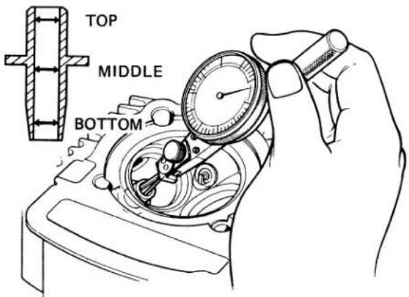
Measure the valve guide at the top, middle and bottom and in two directions at right angles to each other.
| Standard | Service Limit | |
| IN/EX | 5.475-5.485 mm(0.2157-0.2161 in.) | 5.525 mm (Replace)(0.2175 in.) |
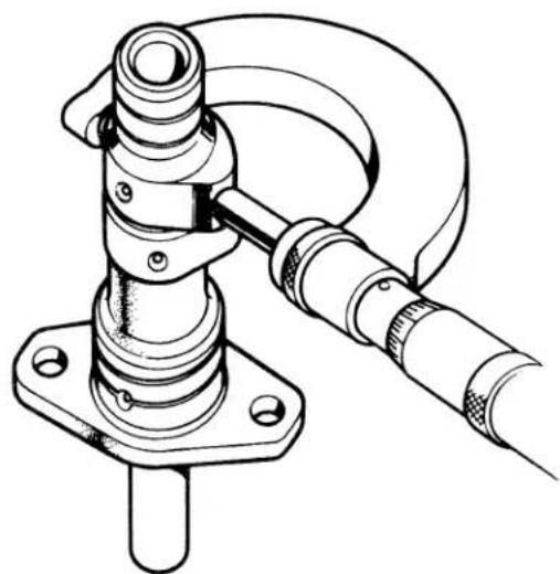
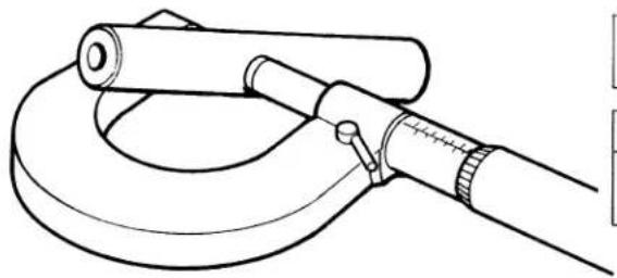
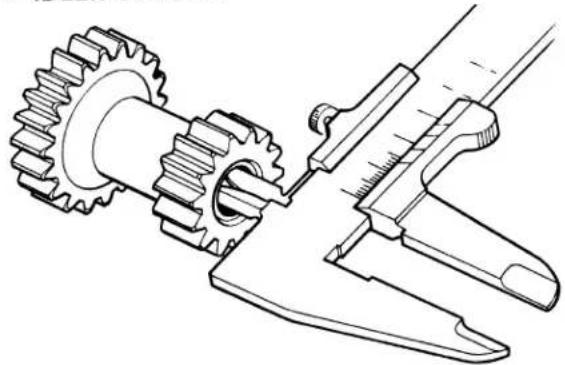
- VALVE STEM O.D.
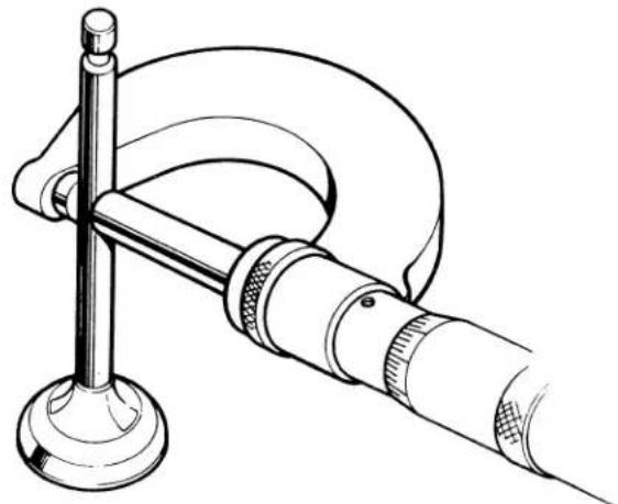
natural_image
Technical line drawing of a micrometer caliper with handle and base mount (no text or symbols)Measure the valve stem at three points along its sliding surface and in two directions at right angles to each other.
| Standard | Service Limit | |
| IN | 5.455-5.465 mm(0.2148-0.2152 in.) | 5.435 mm (Replace)(0.2139 in) |
| EX | 5.435-5.445 mm(0.2140-0.2144 in.) | 5.415 mm (Replace)(0.2132 in.) |
- VALVE FACE WIDTH
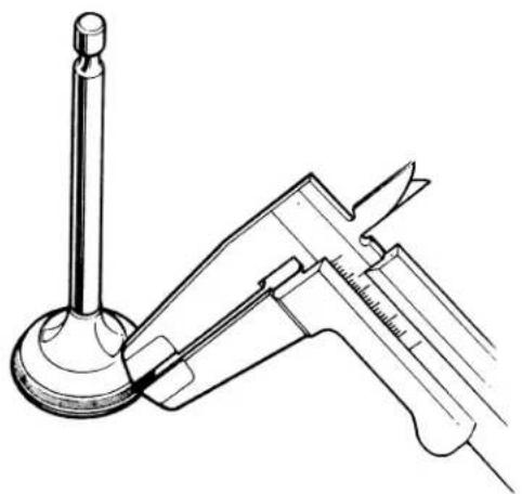
natural_image
Technical line drawing of a mechanical device with a cylindrical component and a lever mechanism (no text or symbols)Measure the valve face width at several points.
| Standard | Service Limit | |
| IN/EX | 1.2-1.5 mm(0.048-0.060 in.) | 1.8 mm (Replace)(0.072 in.) |
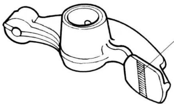
- ROCKER ARM I.D.
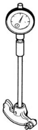
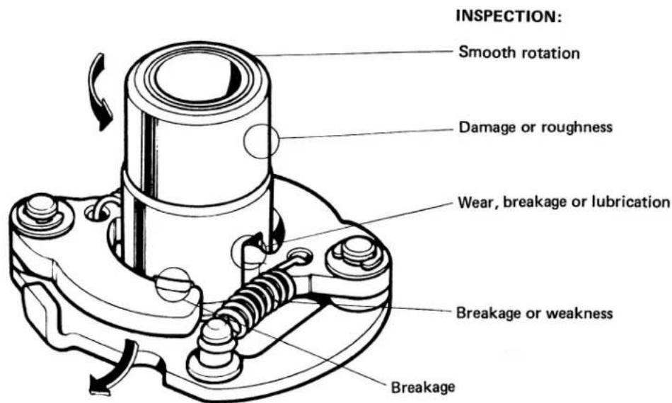
natural_image
Line drawing of a pressure gauge mounted on a stand, no text or symbols presentMeasure the rocker arm I.D. in two direction at right angles to each other.
| Standard | Service Limit | |
| IN/EX | 10.000-10.015 mm(0.3937-0.3943 in.) | 10.10 mm (Replace)(0.3976 in.) |
• ROCKER ARM WEAR/DAMAGE
natural_image
Line drawing of a mechanical component with no visible text or symbolsCheck for wear or damage.
- CAM HEIGHT
natural_image
Technical line drawing of a mechanical clamp or connector assembly (no text or symbols)| Standard | Service Limit | |
| IN/EX | 24.90-24.98 mm(0.9803-0.9835 in.) | 24.6 mm (Replace)(0.9685 in.) |
• CAMSHAFT O.D.
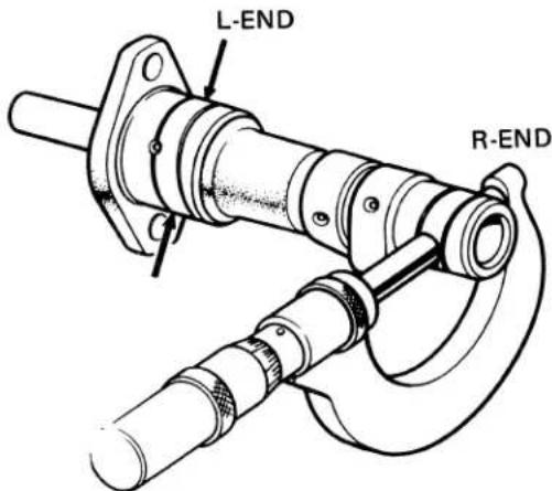
Measure the camshaft in two directions at right angles to each other (both ends).
| Standard | Service Limit | |
| L-END | 25.917-25.930 mm(1.0204-1.0208 in.) | 25.90 mm(1.0197 in.) |
| R-END | 17.927-17.938 mm(0.7058-0.7062 in.) | 17.90 mm (Replace)(0.7047 in.) |
• CAMSHAFT END HOLE I.D.
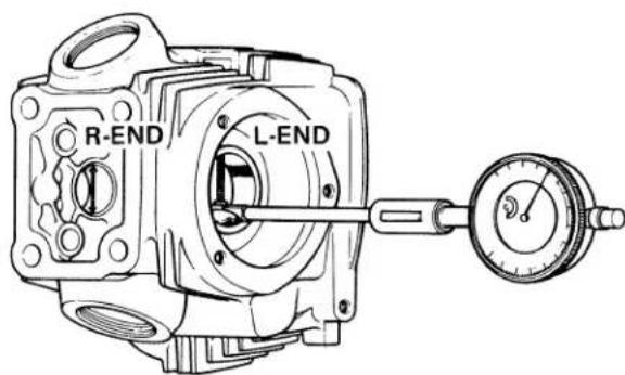
Measure the end hole in two directions at right angles to each other (both ends).
| Standard | Service Limit | |
| L-END | 26.000-26.020 mm(1.0236-1.0244 in.) | 26.05 mm (Replace)(1.0256 in.) |
| R-END | 18.000-18.018 mm(0.7087-0.7094 in.) | 18.05 mm (Replace)(0.7106 in.) |
- VALVE SPRING FREE LENGTH
natural_image
Technical line drawing of a mechanical spring assembly with caliper (no text or symbols)VALVE SPRING FREE LENGTH
| Standard | Service Limit | |
| OUTER SPRING | 31.8 mm(1.252 in.) | 30.6 mm (Replace)(1.205 in.) |
| INNER SPRING | 26.5 mm(1.043 in.) | 25.5 mm (Replace)(1.004 in.) |
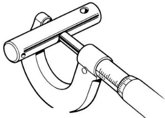
• ROCKER ARM SHAFT O.D.
natural_image
Line drawing of a micrometer caliper tool (no text or symbols present)Measure the rocker arm shaft at its sliding surface in two directions at right angles to each other.
| Standard | Service Limit | |
| IN/EX | 9.972-9.987 mm(0.3926-0.3932 in.) | 9.92 mm (Replace)(0.3906 in.) |
- SPARK ADVANCER
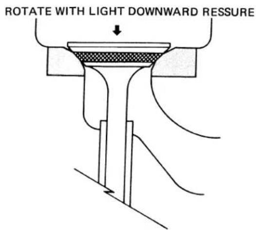
- VALVE SEAT REFACING
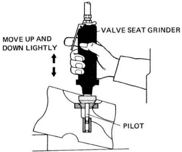
- Check the contact between the valve face and the seat. Coat the valve face lightly with Prussian blue, put the valve into the seat and turn it with light pressure about one full turn. - If the Prussian blue does not transfer evenly to the seat, or if the contact is excessive, the valve must be replaced, and the seat ground with a valve seat grinder.
NOTE
Grinding stones must be dressed before each usage to ensure that they will refinish valve seats accurately. Follow all instructions supplied with the grinder.
- VALVE SEAT REFACING
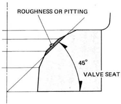
(1) Dress the grinding stones to assure even, uniform grinding of the valve seat.
(2) As a first step in the operation, remove all the roughness or pitting from the seat using the 45^ grinding stone.
NOTE
| Grinding should be performed until all pits in the seat are removed. |
| Grinding Stone (O. D.) | Grinding Angle | |
| IN | 29 mm (1.142 in) | 45^ |
| EX | 26 mm (1.024 in) |
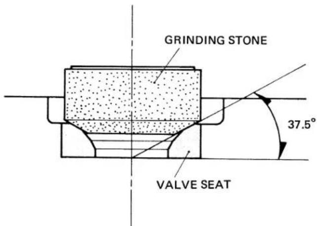
(3) Narrow the seat with the dressed 37.5^ stone.
| Grinding Stone (O. D.) | Grinding Angle | |
| IN | 29 mm (1.142 in) | 37.5° |
| EX | 26 mm (1.024 in) |
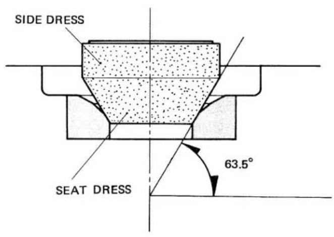
(4) Narrow the seat at the bottom with the 63.5^ grinding stone.
| Grinding Stone | Grinding Angle | |
| IN | 32 mm (1.260 in) | 63.5^ |
| EX | 26 mm (1.024 in) |
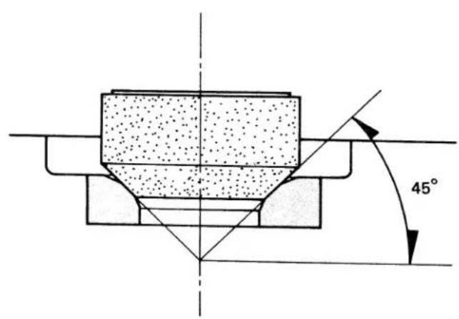
(5) Bring the seat to the correct width and location on the valve face with the 45^ stone as was used in Step (2).
STANDARD VALVE SEAT WIDTH 1.0 mm (0.04 in)
(6) Apply a small amount of fine grinding compound to the valve seat and lap the two surfaces lightly together by rotating the handle of a suction cup.
CAUTION
Do not allow the lapping compound to enter the valve guide.
(7) After lapping, apply a thin coating of Prussian blue to the seat, set the valve into the seat and rotate the valve one full turn.
The contact is satisfactory if the blue is transferred to the center of the valve evenly.
Perform the following operations after assembling:
Cam chain tensioner adjustment. . . . . . . . . . . . . . . . . . . . . . . . . . . . . . . . . . . . . . . . . . . . . . . . . . . . . . . . . . . . . . . . . . . . . . . . . . . .
Cylinder compression test Page 29
a. DISASSEMBLY/ASSEMBLY
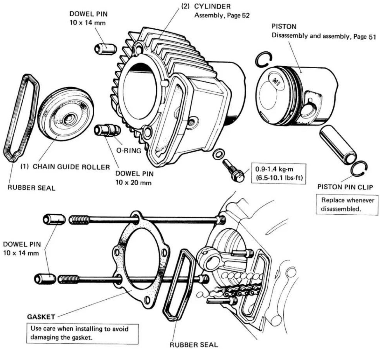
- PISTON
CAUTION
Avoid damaging the piston when installing.
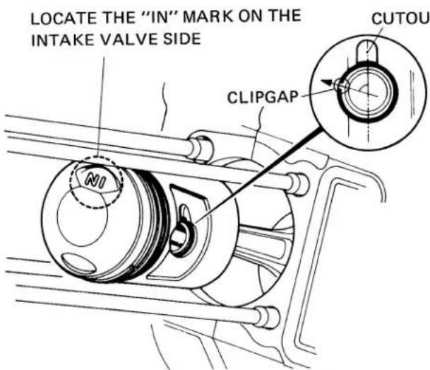
Install the clip so that the clip gap and cutout in the piston are not aligned.
Be careful to prevent the clip from falling into the crank-case.
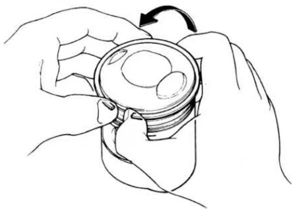
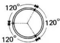
- PISTON RING
CAUTION
Avoid damaging the piston when installing and removing rings.
REMOVE RINGS IN THE ARROW DIRECTION.
natural_image
Line drawing of two hands holding a cylindrical container with a circular opening, rotating around it (no text or symbols)Position piston rings so end gaps are 120^ apart and no gap is in line with the ends of the piston pin.
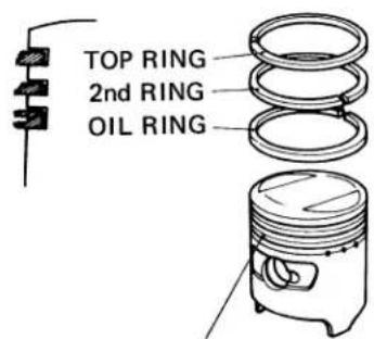
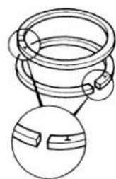
natural_image
Diagram of a mechanical component with two circular views showing internal features (no text or symbols)Before installing the piston rings, clean the ring grooves and oil holes thoroughly.
Install the rings with the markings up.
• CYLINDER INSTALLATION
Apply a thin coat of oil on the cylinder wall and piston rings before installing the cylinder. As the cylinder is installed, compress the piston rings with your fingers to ease entry of the piston into the cylinder.
CAUTION
Avoid damaging the piston rings when inserting the piston in the cylinder.
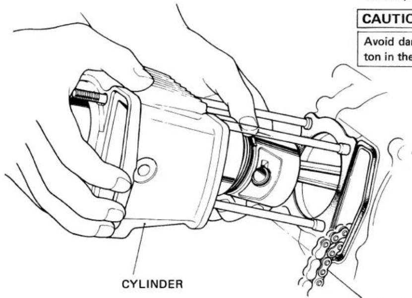
CAM CHAIN
After the piston has entered the cylinder, route the chain forward through the hole in the cylinder.
• GUIDE ROLLER ASSEMBLY
b INSPECTION
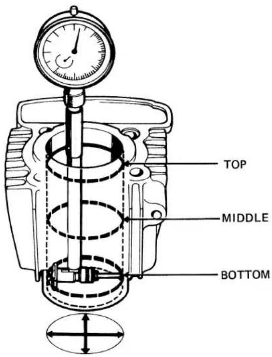
- CYLINDER
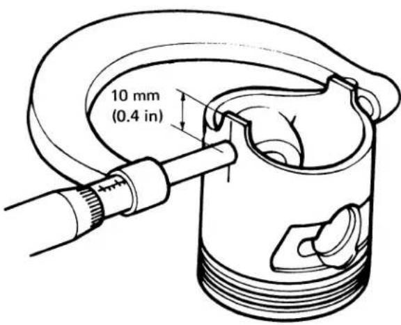
- PISTON O.D.
Measure I.D. of the cylinder in at least three places, top, middle and bottom of piston travel, and in two directions at right angles to each other.
| Standard | Service Limit | |
| I.D. | 50.00-50.01 mm(1.9685-1.9689 in.) | 50.10 (Repair or replace)(1.9724 in.) |
| TAPER | 0.01 mm(0.0004 in.) | 0.05 mm (Repair or replace)(0.002 in.) |
| OUT-OF-ROUND | 0.01 mm(0.0004 in.) | 0.05 mm (Repair or replace)(0.002 in.) |
If the above limits are exceeded, the cylinder must be rebored and oversize piston and piston rings fitted.
STANDARD OVERSIZES:
0.25 mm, 0.50 mm, 0.75 mm, 1.00 mm
(0.01 in, 0.02 in 0.03 in 0.04 in)
Measurements should be taken at a point 10 mm (0.4 in.) from the lower end.
| Standard | Service Limit |
| 49.97-49.99 mm(1.9673-1.9681 in.) | 49.80 mm (Replace)(1.9606 in.) |
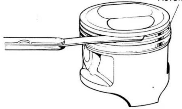
- PISTON-TO-PISTON RING CLEARANCE
PISTON RING
natural_image
Line drawing of a piston-cylinder joint with a fork inserted, showing internal components (no text or labels)| Standard | Service Limit |
| 0.010-0.045 mm(0.0004-0.0018 in.) | 0.12 mm (Replace)(0.0047 in.) |
- PISTON PIN BORE I.D.
natural_image
Technical line drawing of a piston-cylinder joint with pressure gauge (no text or symbols)| Standard | Service Limit |
| 14.002-14.008(0.5513-0.5515 in.) | 14.04 mm (Replace)(0.5528 in.) |
- PISTON RING END GAP
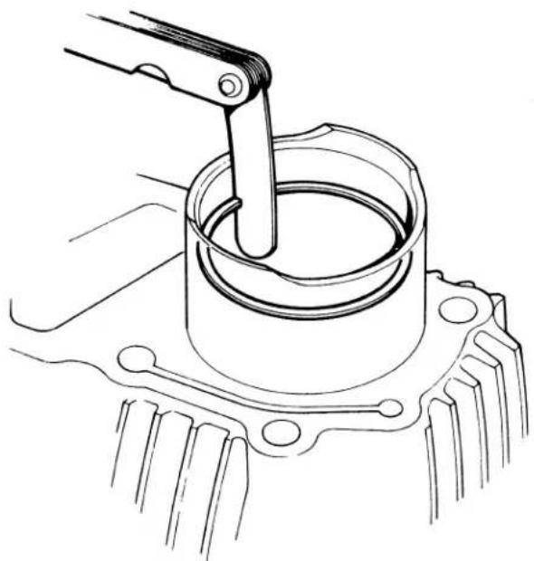
natural_image
Technical line drawing of a mechanical assembly with a lever and housing (no text or symbols)| Measure the ring end gap with the ring inserted in the cylinder to a point 10 mm (0.4 in.) from bottom. |
| Standard | Service Limit | |
| TOP/SECOND | 0.15-0.35 mm.(0.006-0014 in.) | 0.50 mm (Replace)(0.02 in.) |
| OIL | 0.15-0.40 mm(0.006-0.016 in) | 0.50 (Replace)(0.02 in) |
- PISTON RING THICKNESS
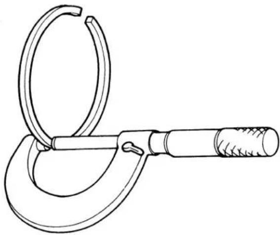
natural_image
Line drawing of a micrometer caliper with handle and ring (no text or symbols)- PISTON PIN O.D.
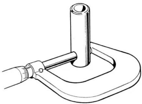
natural_image
Technical line drawing of a mechanical clamp or clamp device with a cylindrical component inserted into a curved base (no text or symbols)Take measurements at several points.
| Standard | Service Limit | |
| TOP and SECOND | 1.175-1.190 mm(0.0463-0.0469 in.) | 1.13 mm (Replace)(0.0445 in.) |
| OIL RING | 2.475-2.490 mm(0.0974-0.0980 in.) | 2.43 mm (Replace)(0.0957 in.) |
| Standard | Service Limit |
| 13.994-14.000 mm(0.5509-0.5513 in.) | 13.960 mm (Replace)(0.5496 in.) |
• LUBRICATION CIRCUIT DIAGRAM
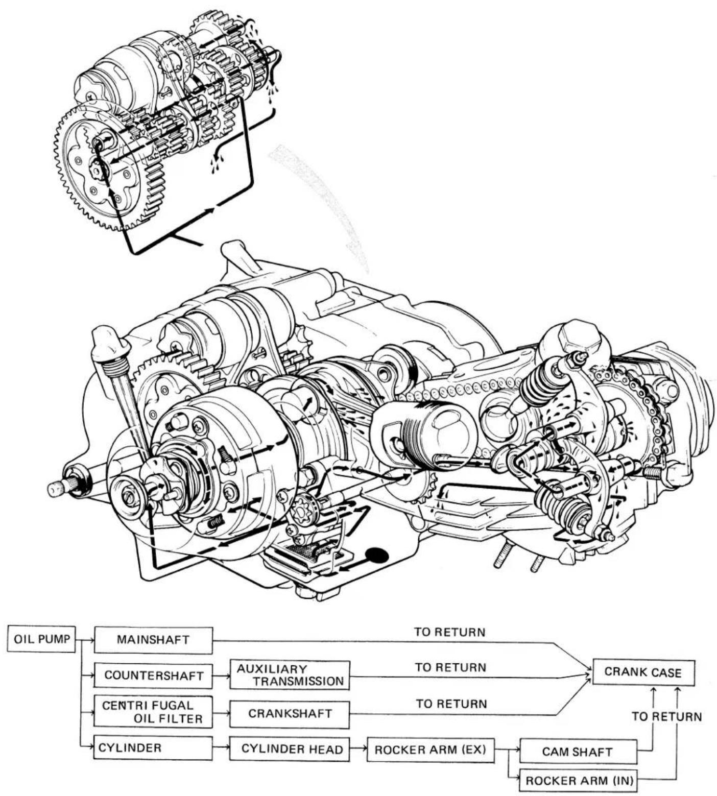
flowchart
graph TD
    A["Main Shaft"] --> B["COUNTERSHAFT"]
    B --> C["CENTRI FUGAL OIL FILTER"]
    C --> D["CYLINDER"]
    D --> E["AUXILIARY TRANSMISSION"]
    E --> F["CRANKSHAFT"]
    F --> G["CYLINDER HEAD"]
    G --> H["ROCKER ARM (EX)"]
    H --> I["CAM SHAFT"]
    I --> J["ROCKER ARM (IN)"]
    J --> K["TO RETURN"]
    K --> L["TO RETURN"]
    L --> M["TO RETURN"]
    M --> N["TO RETURN"]
    N --> O["TO RETURN"]
    O --> P["TO RETURN"]
    P --> Q["TO RETURN"]
    Q --> R["TO RETURN"]
    R --> S["TO RETURN"]
    S --> T["TO RETURN"]
    T --> U["TO RETURN"]
    U --> V["TO RETURN"]
    V --> W["TO RETURN"]
    W --> X["TO RETURN"]
    X --> Y["TO RETURN"]
    Y --> Z["TO RETURN"]
    Z --> AA["TO RETURN"]
    AA --> AB["TO RETURN"]
    AB --> AC["TO RETURN"]
    AC --> AD["TO RETURN"]
    AD --> AE["TO RETURN"]
    AE --> AF["TO RETURN"]
    AF --> AG["TO RETURN"]
    AG --> AH["TO RETURN"]
    AH --> AI["TO RETURN"]
    AI --> AJ["TO RETURN"]
    AJ --> AK["TO RETURN"]
    AK --> AL["TO RETURN"]
    AL --> AM["TO RETURN"]
    AM --> AN["TO RETURN"]
- Drain engine oil.
- Remove the step bar and shift pedal.
DRUM STOPPER
Disassembly and assembly, Page 60
After installation, check and adjust the clutch, Page 28.
a. DISASSEMBLY/ASSEMBLY
- CLUTCH REMOVAL AND INSTALLATION
- Drain the engine oil
- Remove the clutch outer cover.
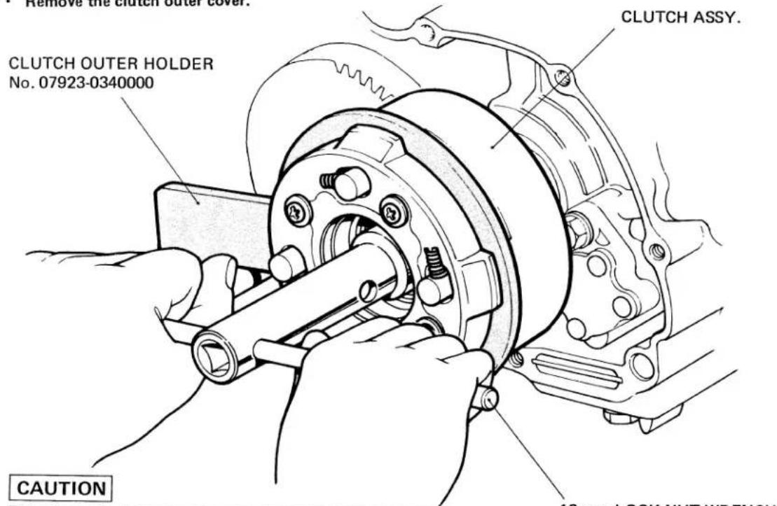
CAUTION
Do not hammer the clutch into or out of position, as this will result in a damaged clutch or other defect.
16 mm LOCK NUT WRENCH No. 07916-3710000
- LOCK WASHER INSTALLATION
CLUTCH DISASSEMBLY/ASSEMBLY
• DAMPER SPRING DISASSEMBLY/ASSEMBLY
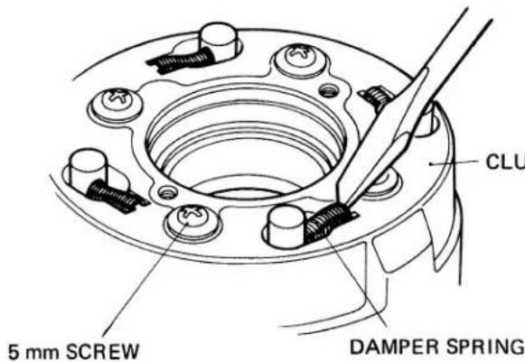
Tighten these screws in a criss-cross pattern and in two or more steps.
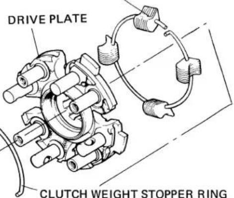
- CLUTCH WEIGHT INSTALLATION
CLUTCH WEIGHT STOPPER RING
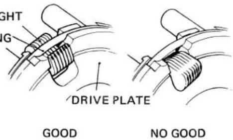
CLUTCH WEIGHT
DRIVE PLATE
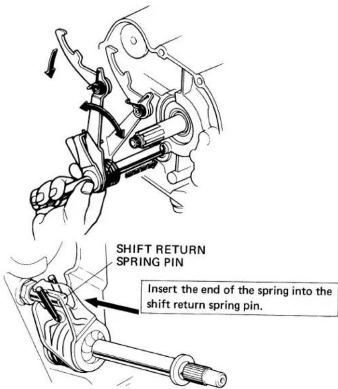
- SHIFT SPINDLE DISASSEMBLY/ASSEMBLY
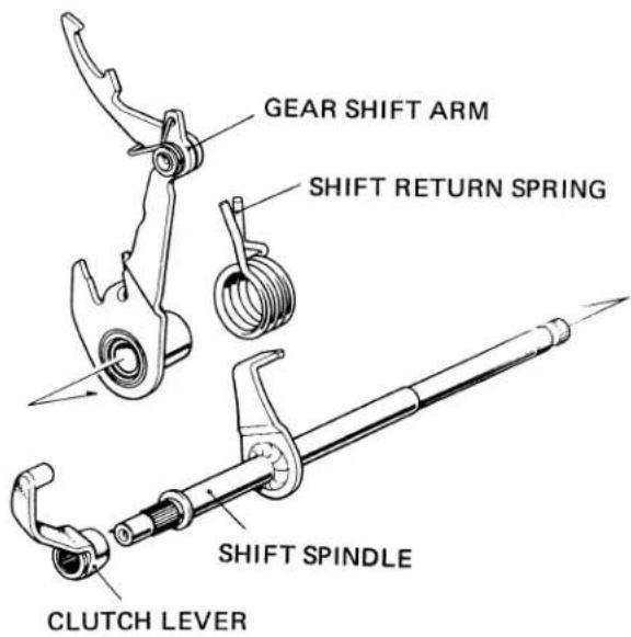
After installing the lever, check for operation.
The shift spindle hole in the left crankcase cover is provided with an oil seal and care must be used in installing the spindle to avoid damage to it by rotating it by hand.
-
DRUM STOPPER INSTALLATION
-
DRUM STOPPER PLATE INSTALLATION
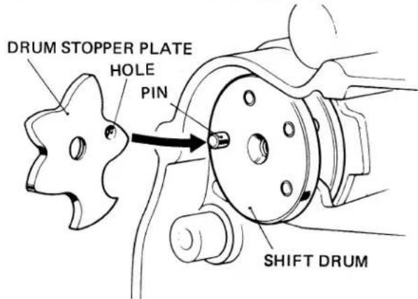
Hold the plate against the drum firmly until the pin on the drum has entered the pin hole.
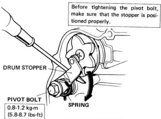
After the bolt has been tightened, check the stopper for operation.
- CLUTCH LEVER INSTALLATION
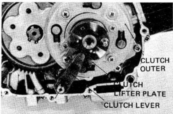
Install the clutch lever towards the center of the clutch as shown,
Check that the end of the rotor shaft engages the groove in the end of the sprocket shaft.
b. INSPECTION
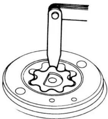
• OIL PUMP ROTOR TIP CLEARANCE
natural_image
Technical line drawing of a mechanical gear assembly with a lever and flange (no text or symbols)- OIL PUMP OUTER ROTOR-TO-BODY CLEARANCE
| Standard | Service Limit |
| 0.15 mm(0.006 in.) | 0.2 mm (Replace)(0.008 in.) |
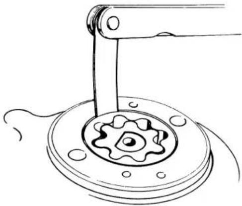
natural_image
Technical line drawing of a mechanical assembly with a gear and shaft (no text or symbols)| Standard | Service Limit |
| 0.15-0.20 mm(0.006-0.008 in.) | 0.25 mm (Replace)(0.010 in.) |
Check the rotors for wear, nicks or scratches, and for freedom of any foreign matter.
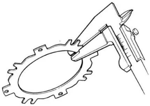
• FRICTION DISC THICKNESS
natural_image
Technical line drawing of a mechanical gear and caliper assembly (no text or symbols)| Standard | Service Limit |
| 2.8-2.9 mm(0.1102-0.1142 in.) | 2.4 mm (Replace)(0.0945 in.) |
Check the friction discs, replacing those which are found to be worn or damaged.
- CLUTCH PLATE THICKNESS
natural_image
Technical line drawing of a mechanical device with gear and caliper (no text or symbols)| Standard | Service Limit |
| 1.93-2.07 mm(0.0760-0.0815 in.) | 1.85 mm (Replace)(0.0729 in.) |
Take measurements at several points.
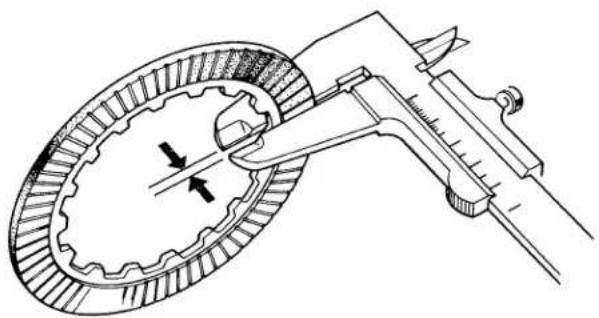
- CLUTCH PLATE WARPAGE
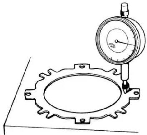
natural_image
Technical line drawing of a mechanical measurement setup with a dial indicator and gear base (no text or symbols)| Standard | Service Limit |
| 0.2 mm(0.008 in.) | 0.5 mm (Replace)(0.020 in.) |
The plate must be within specifications along its entire circumference.
- CLUTCH SPRING FREE LENGTH
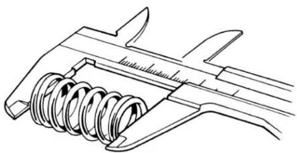
natural_image
Technical line drawing of a mechanical caliper with spring mechanism (no text or symbols)FREE LENGTH
| Standard | Service Limit |
| 27 mm(1.0630 in.) | 26 mm (Replace)(1.0236 in.) |
- CLUTCH DRIVE GEAR I.D.
| Standard | Service Limit |
| 24.00-24.02(0.9449-0.9457 in.) | 24.15 mm (Replace)(0.9508 in.) |
Check the driven gear if the drive gear is worn or damaged.
- CLUTCH CENTER GUIDE
natural_image
Technical drawing of a mechanical component with threaded shaft and central housing (no text or symbols)| Standard | Service Limit | |
| O.D. | 22.0-22.1 mm(0.8661-0.870 in) | 21.85 mm (Replace)(0.8602 in) |
| GUIDE-TO-CRANKSHAFT CLEARANCE | 0.005-0.047 mm(0.0002-0.0019 in) | 0.15 mm (Replace)(0.060 in) |

a. DISSASEMBLY/ASSEMBLY
b. INSPECTION
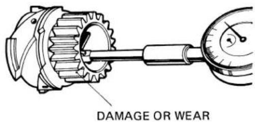
• IDLER GEAR I.D.
natural_image
Technical line drawing of a mechanical gear assembly with caliper (no text or symbols)• IDLER SHAFT O.D.
natural_image
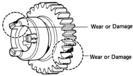
Technical line drawing of a micrometer caliper (no text or symbols present)- GEARS
CHECK FOR WEAR OR DAMAGE
natural_image
Technical line drawing of a mechanical gear assembly (no text or symbols)CHECK FOR WEAR OR BURNING
| Standard | Service Limit |
| 13.000-13.018 mm0.5118-0.5125 in.) | 13.10 mm(0.5157 in) |
| Standard | Service Limit |
| 12.966-12.984 mm(0.5105-0.5112 in) | 12.85 mm(0.5140 in) |
CHECK FOR WEAR OR DAMAGE
natural_image
Technical line drawing of a mechanical gear assembly (no text or symbols)CHECK FOR WEAR OR DAMAGE
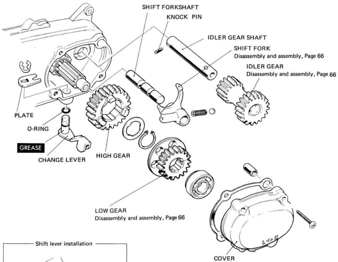
- SHIFT FORK
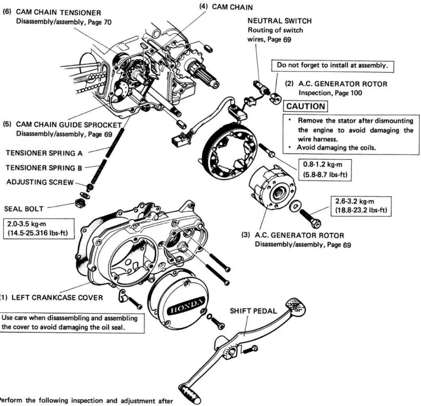
7. A.C.GENERATOR/CAM CHAIN TENSIONER
• Before disassembly, drain the oil from the engine.
- Remove the auxiliary transmission.
- Perform Steps (4) thru (6) after the cylinder has been removed.
Perform the following inspection and adjustment after assembling the tensioner:
Cam chain tension Page 26
a. DISASSEMBLY/ASSEMBLY
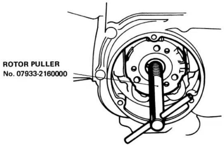
• A.C. GENERATOR ROTOR REMOVAL
• NEUTRAL SWITCH WIRE INSTALLATION
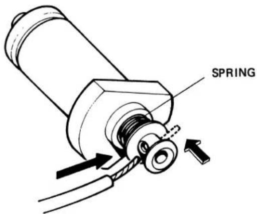
Route the end of the wire through the hole in the switch while compressing the spring.
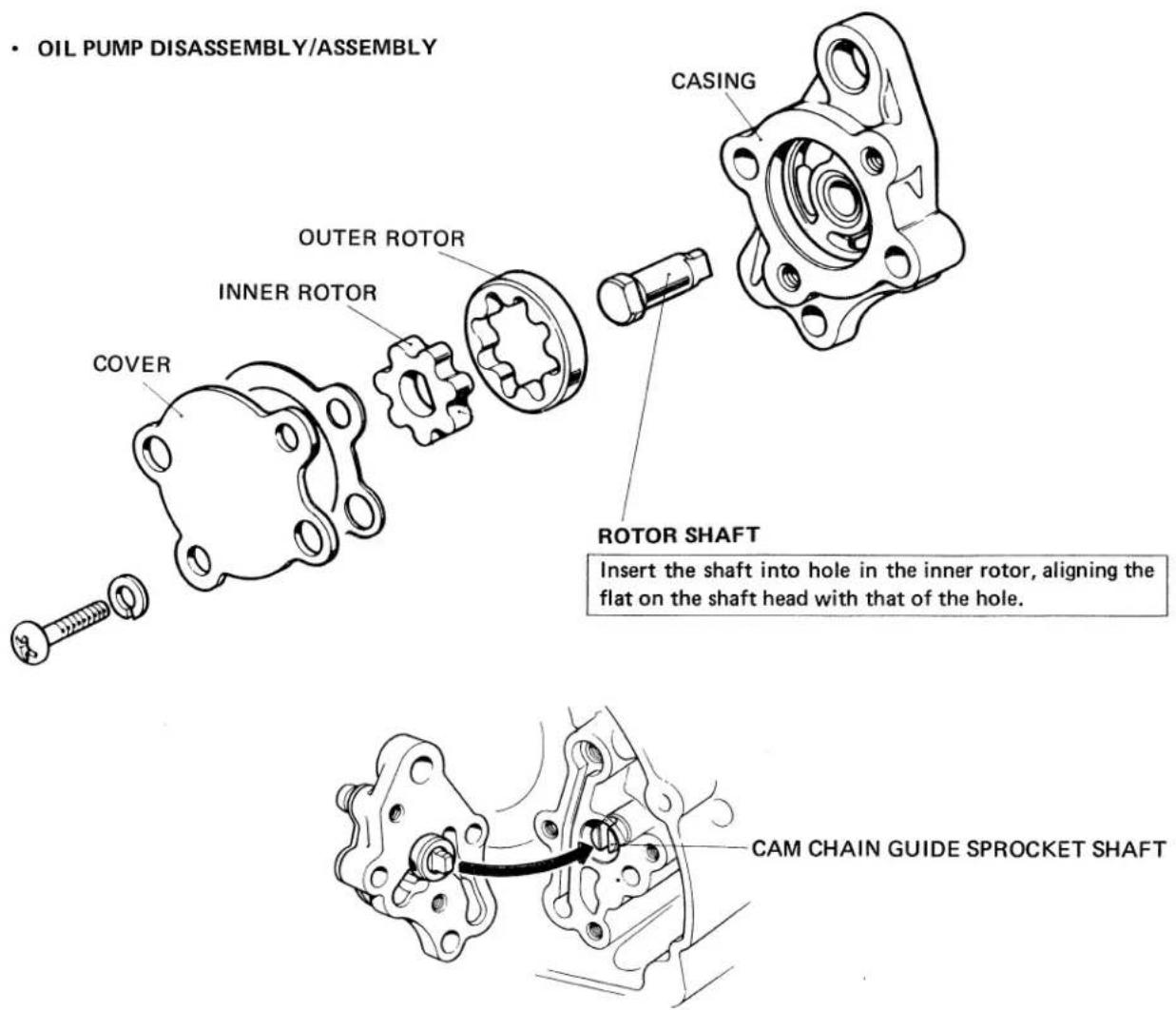
• CAM CHAIN GUIDE SPROCKET INSTALLATION
natural_image
Mechanical gear mechanism diagram showing gear meshing and rotational motion (no text or labels)- Align the cutout in the end with the pump rotor shaft while rotating the sprocket by hand.
- Apply clean engine oil to the shaft during assembly.
• CAM CHAIN TENSIONER DISASSEMBLY/ASSEMBLY
(1) Remove the cylinder head.
(2) Remove the cam chain.
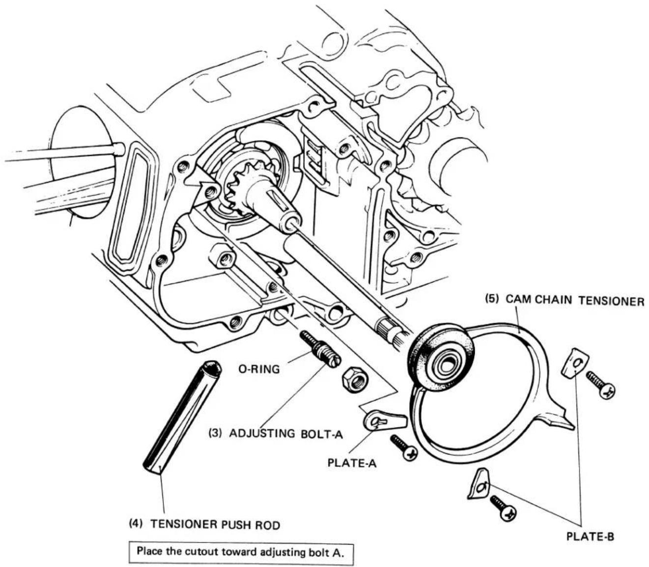
Parts (4) and (5) can be removed as an assembled unit.
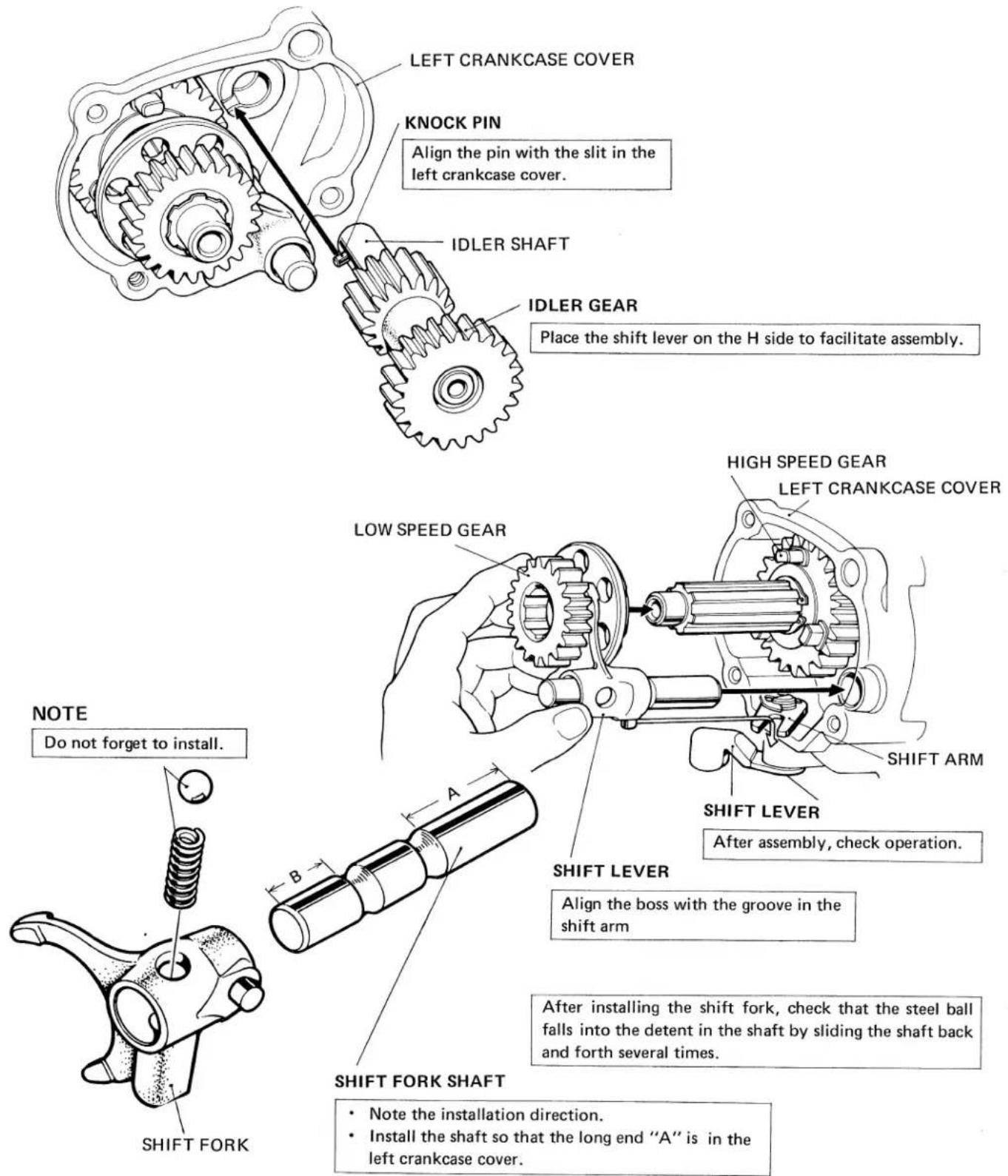
a. DISASSEMBLY/ASSEMBLY
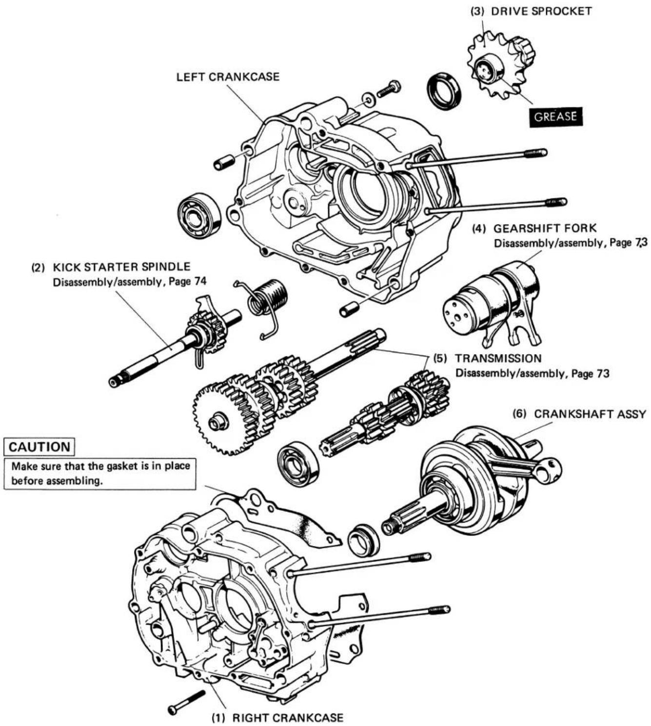
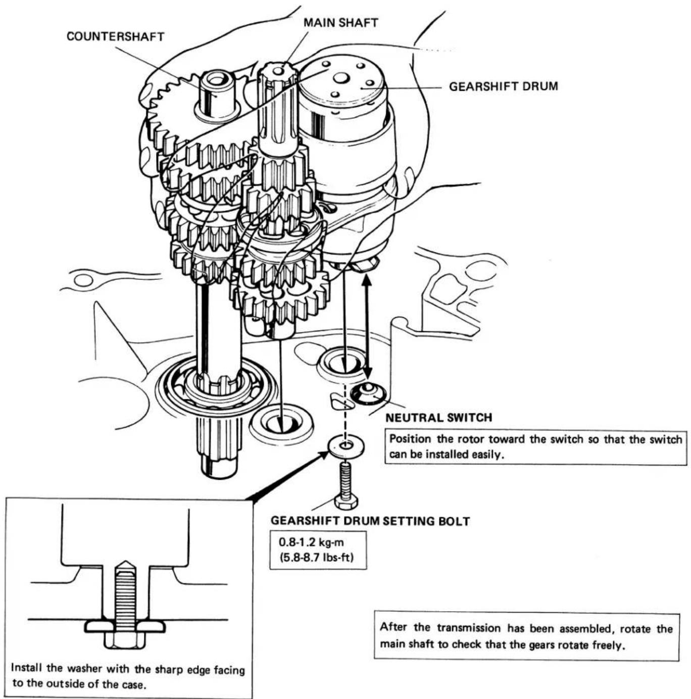
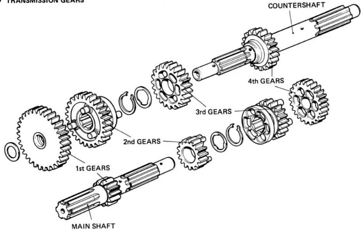
• TRANSMISSION ASSEMBLY
- With the gearshift drum in place, engage the counter-gear assembly with the main drive gear assembly. Then, while holding the assemblies together, slip the ends of the shafts into holes in the left crankcase.
• TRANSMISSION GEARS
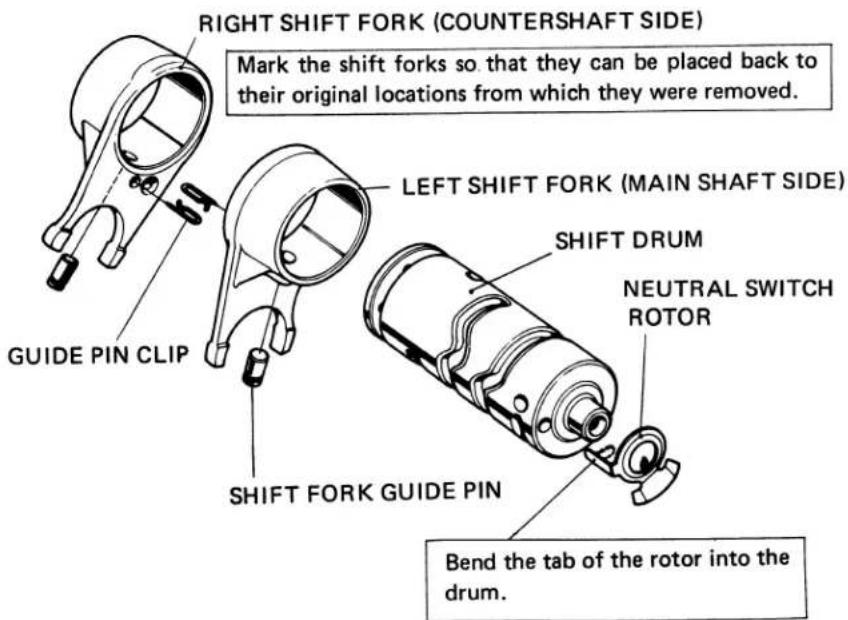
• GEARSHIFT DRUM ASSEMBLY
- KICK STARTER
- Assemble the ratchet spring (1), stopper (2) and return spring (3) in the order named.
(2) STOPPER
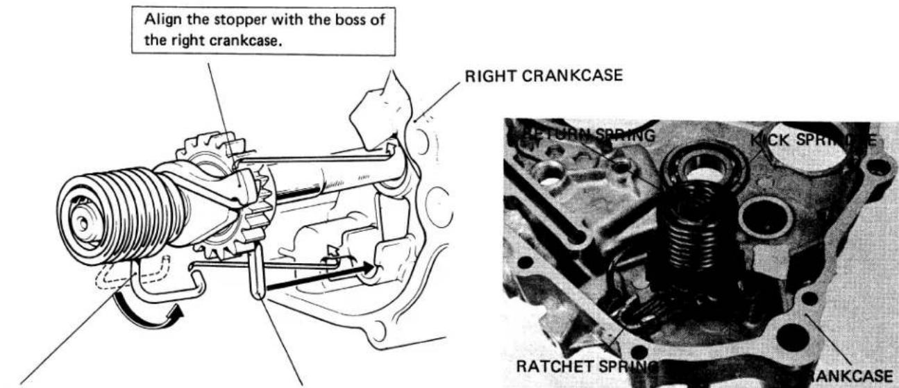
(3) RETURN SPRING
Place this end of the return spring into hole in the cutout in the right crankcase.
(1) RATCHET SPRING
Line up the spring with the groove in the right crankcase.
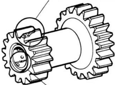
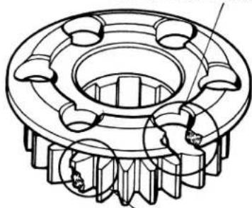
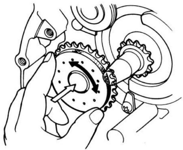
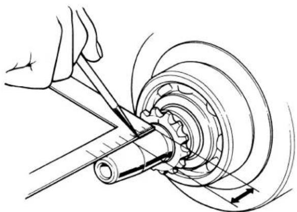
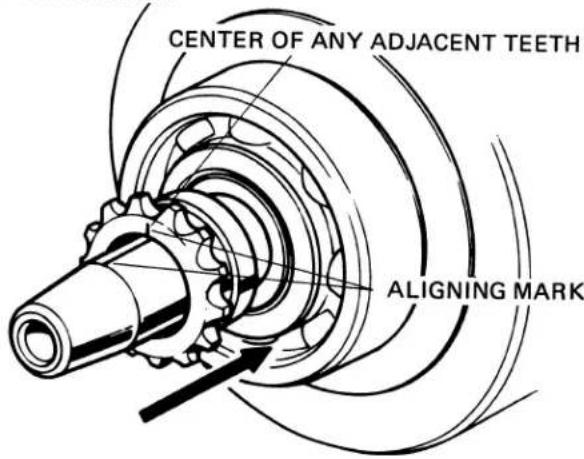
• TIMING GEAR
· DISASSEMBLY
Scribe an aligning mark over the crankshaft from the center between two teeth. Then, remove the sprocket.
natural_image
Technical illustration of a mechanical assembly with a tool and rotating component (no text or symbols)NEVER SCRIBE ACROSS OIL SEAL CONTACTING SURFACES.
· ASSEMBLY
Scribe an aligning mark over a new sprocket at the center of two teeth. Install the sprocket on the crankshaft with the marking on the sprocket aligned with the marking on the crankshaft.
b. INSPECTION
• TRANSMISSION GEARS
• GEARSHIFT DRUM/GUIDE PIN INSPECTION
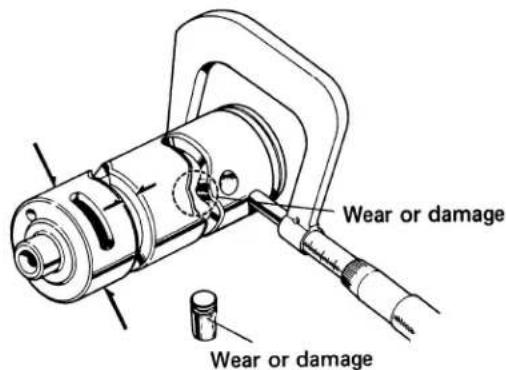
• GEARSHIFT FORK I.D.
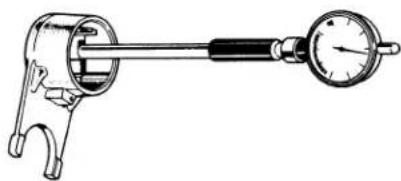
natural_image
Technical line drawing of a mechanical clamp or dial with a handle and base (no text or symbols)• GEARSHIFT FORK END THICKNESS
natural_image
Technical line drawing of a mechanical clamp or tool handling a circular component (no text or symbols)| Standard | Service Limit | |
| O.D. | 41.950-41.975 mm(1.6516-1.6526 in.) | 41.80 mm (Replace)(1.6457 in.) |
| Groove width | 6.1-6.2 mm(0.2402-0.2441 in.) | 6.4 mm (Replace)(0.2520 in.) |
Check the bore diameter in two positions at right angle to each other.
| Standard | Service Limit |
| 42.00 mm(1.6535 in.) | 42.10 mm (Replace)(1.6575 in.) |
| Standard | Service Limit |
| 5.96-6.04 mm(0.2346-0.2378 in.) | 5.70 mm (Replace)(0.2244 in.) |
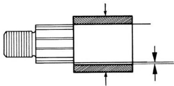
- CONNECTING ROD SMALL END I.D.
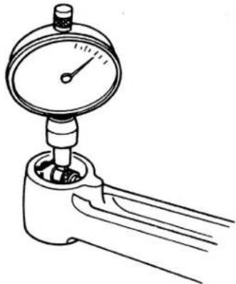
natural_image
Line drawing of a pressure gauge attached to a handle, with multiple force lines visible (no text or symbols)| Standard | Service Limit |
| 14.012-14.028 mm(0.5517-0.5523 in.) | 14.05 mm (Replace)(0.5531 in.) |
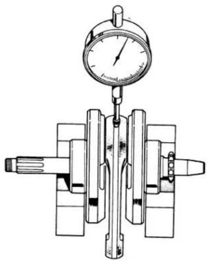
- CONNECTING ROD BIG END SIDE CLEARANCE
natural_image
Technical line drawing of a mechanical assembly with gears and shafts (no text or symbols)| Standard | Service Limit |
| 0.10-0.35 mm(0.004-0.019 in.) | 0.8 mm (Replace)(0.032 in.) |
- CONNECTING ROD BIG END RADIAL CLEARANCE
natural_image
Technical illustration of a mechanical pressure gauge assembly (no text or symbols)Measure the radial clearance in two directions.
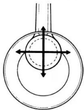
natural_image
Pure diagram of concentric circles with directional arrows, no text or symbols present| Standard | Service Limit |
| 0-0.01 mm(0-0.0004 in.) | 0.05 mm (Replace)(0.002 in) |
• CRANKSHAFT BEARING PLAY
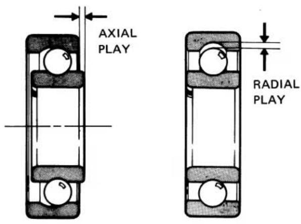
| Standard | Service Limit | |
| Axial play | 0.10-0.35 mm(0.004-0.019 in.) | 0.80 mm (Replace)(0.032 in.) |
| Radial play | 0.01 mm(0-0.0004 in.) | 0.05 mm (Replace)(0.002 in.) |
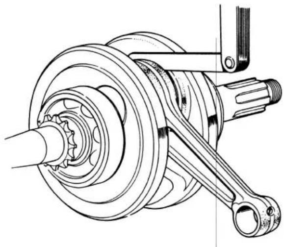
• CRANKSHAFT RUNOUT
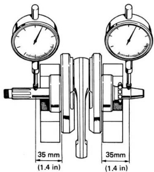
| Standard | Service Limit |
| 0-0.015 mm(0-0.0006 in.) | 0.1 mm (Replace)(0.004 in.) |
Measure runout at points shown.
1977 (K8) model
WARNING
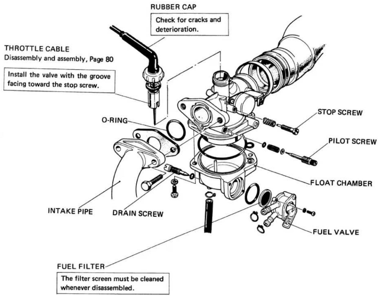
- Drain fuel from the carburetor by loosening the drain screw.
- Do not bring an open flame near gasoline. Wipe off spilled gasoline at once.
Perform the following operations after assembling the carburetor:
Throttle grip free play .... Page 25
Idle speed adjustment Page 25
WARNING
Clamp fuel tank tubes to seal them before disconnecting the tubes from the carburetor or dismantling the fuel valve.
- Check each tube for cracks or deterioration.
• To reconnect the tubes, refer to page 96.
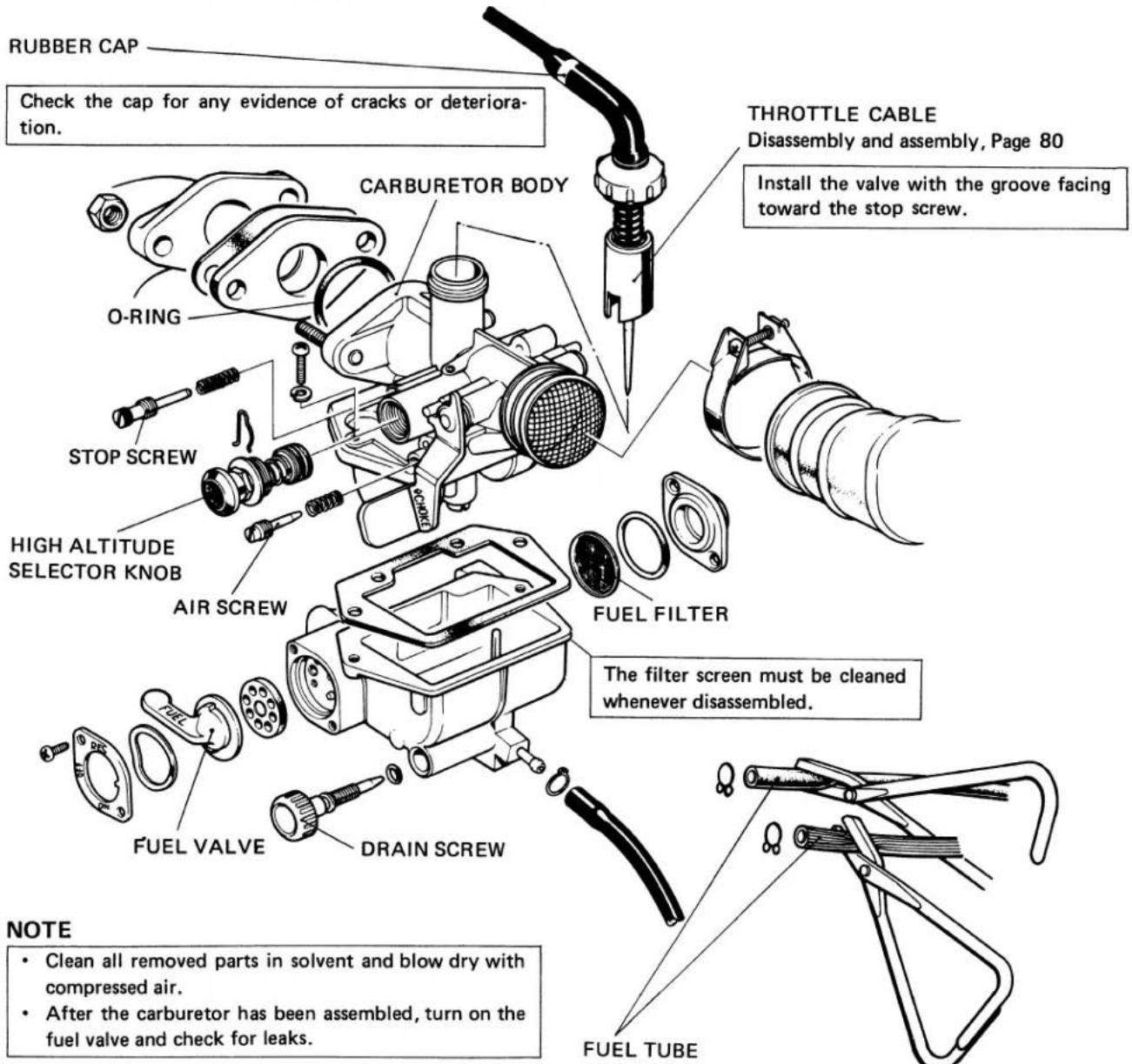
1978(K9) model
- Clean all removed parts in solvent and blow dry with compressed air.
- After the carburetor has been assembled, turn on the fuel valve and check for leaks.
Perform the following operations after assembling the carburetor:
Throttle grip free play .... Page 25
Idle speed adjustment Page 25
a. DISASSEMBLY/ASSEMBLY
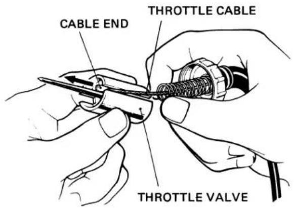
- THROTTLE VALVE
- Disconnect the end of the throttle cable from the groove in the throttle valve.
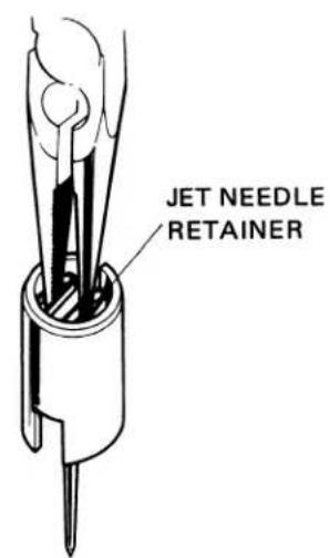
Set the jet needle retainer in the bottom properly at assembly.
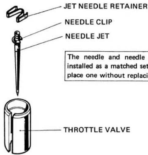
The needle and needle jet must be installed as a matched set. Do not replace one without replacing the other.
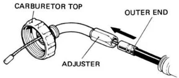
- At assembly, turn in the adjuster all the way as far as it will go.
• Make sure that the outer end of the throttle cable is inserted in the hole in the cable adjuster properly.
• CARBURETOR FLOAT AND JETS (1977 K8 model)
• CARBURETOR FLOAT AND JETS (1978 K9 model)
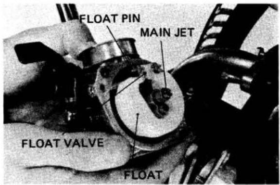
(1) Turn the fuel valve to OFF.
(2) Drain fuel from the carburetor by loosening the drain screw.
(3) Remove the throttle valve and air cleaner band. Remove the carburetor.
(4) Remove the float chamber for access to the float and jets.
WARNING
Gasoline is inflammable.
CAUTION
- Use extreme caution in assembling and disassembling the carburetor to avoid damaging the carburetor jets.
- Clean all removed parts in solvent and blow with compressed air.
b. INSPECTION
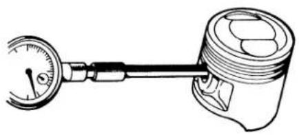
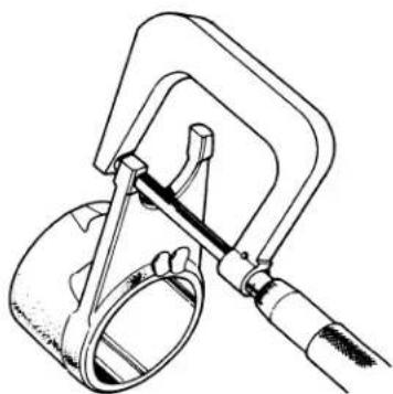
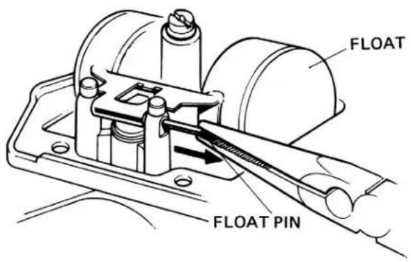
- FLOAT HEIGHT
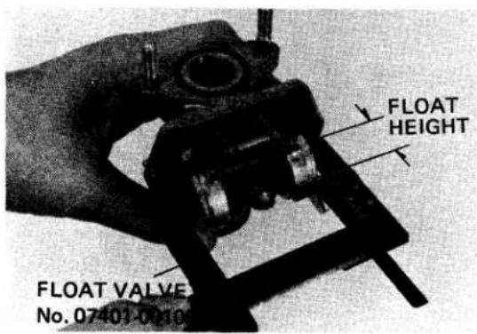
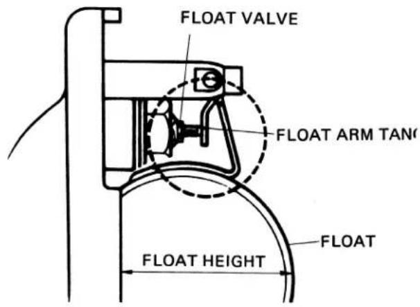
(1) Hold the carburetor with its main bore in a vertical position, so the float arm tang will just close the float valve, without compressing the spring loaded pin in the end of the valve.
(2) Position the gauge on the carburetor with the end of the float height indicator against the float. If the gauge has been set to the specified float height, and the carburetor float level is properly adjusted, the end of the indicator will just touch the float, without causing the float to move.
(3) If float height is found to be incorrect, carefully bend the float arm tang toward or away from the float valve until the specified float height is obtained.
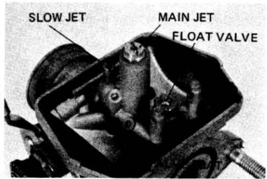
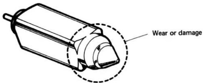
- FLOAT VALVE
• CARBURETOR SETTING TABLE
| 1977 (K8) model | 1978 (K9) model | |
| Identification mark | 556A | B27A |
| Main jet No. | # 62 | #65 |
| Slow jet No. | # 35 | #38 |
| Jet needle setting | 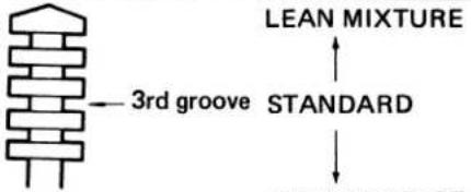 RICH MIXTURE RICH MIXTURE | 2nd groove |
| Air screw opening | 1 turn | 1-1⁄4 |
| Float height | 20 mm (0.8 in.) | 10.7 mm (0.43 in) |
| Idle speed | 1,300 rpm | ← |
After assembly, perform the following operations:
Throttle grip free play adjustment ..... Page 25
Brake lever free play adjustment ..... Page 30
a. DISASSEMBLY/ASSEMBLY
- HANDLEBAR

THROTTLE CABLE
Insert the end of the throttle cable in the holes in the throttle grip. Then make sure the cable is centered in the groove in the grip.
FRONT BRAKE STOPLIGHT SWITCH
Tighten the forward screw first, then tighten the rear screw.
BRAKE LEVER PIVOT BOLT
Do not tighten the bolt sufficiently to bind the brake lever.
Make sure that the lever operates freely, then tighten the lock nut.
BRAKE LEVER
LOCK NUT
HANDLEBAR UPPER HOLDER INSTALLATION
• Install the clamp with the punch mark forward.
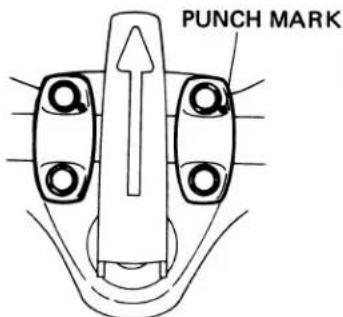
• Tighten the forward bolts first.
ENGINE STOP SWITCH
Align the dowel hole in the handlebar with the dowel on the switch.
0.8-1.2 kg-m
(5.8-8.7 lbs-ft)
HANDLEBAR
LOWER HOLDER
HANDLEBAR INSTALLATION
natural_image
Technical line drawing of a mechanical clamp or bracket assembly (no text or symbols)PUNCH MARK
Install the handlebar with the punch marks aligned with the top of the lower holders.
TURN SIGNAL INSTALLATION
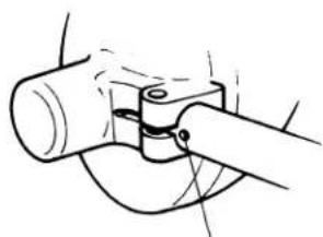
natural_image
Simple line drawing of a mechanical clamp or bracket assembly (no text or symbols)PUNCH MARK
Align the punch mark on the mount with the split in the signal.
- FRONT WHEEL
NOTE
Install tire with arrow pointing in direction of rotation.
BRAKE SHOE INSTALLATION
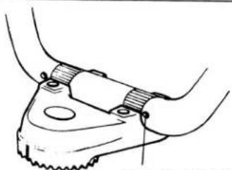
- DRIVING WHEEL BEARING
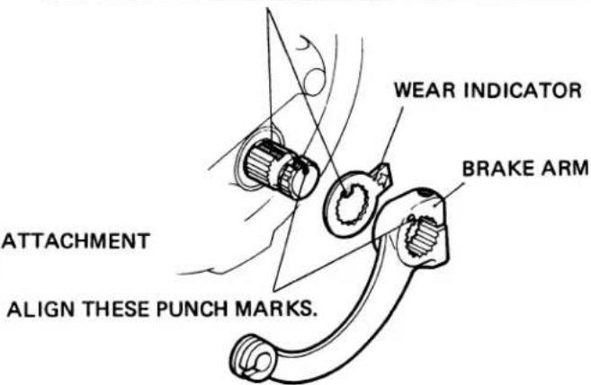
- BRAKE ARM INSTALLATION
Align the tab on the indicator with the cutouts in the brake arm.
NOTE
- Use caution in driving the bearing not to allow it to tilt.
• Install the bearing with the sealed end facing outside.
• STEERING STEM
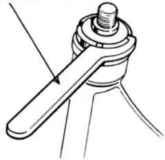
STEERING HEAD TOP THREAD NUT
36 mm PIN SPANNER
No. 07902-0010000
natural_image
Technical line drawing of a mechanical clamp or fastener assembly (no text or symbols)Screw in the top thread nut until resistance is felt, then, back it off about 18 turn to ensure smooth rotation without play in all directions.
6.0 - 7.0 kg-m (43.4 - 50.7 lbs-ft)
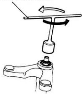
STEERING STEM NUT
STEERING STEM NUT REMOVAL
STEERING STEM NUT WRENCH
No. 07915-0300000
natural_image
Mechanical assembly diagram showing a lever and handle mechanism (no text or labels)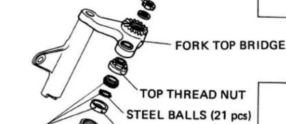
GREASE
TOP THREAD NUT
STEEL BALLS (21 pcs)
OP BALL RACE
BALL RACE DRIVER
No. 07944-1150001
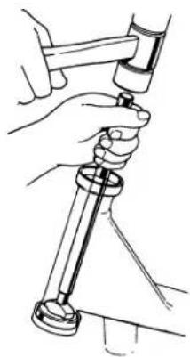
natural_image
Illustration of a hand using a tool to adjust or install a mechanical component (no text or symbols visible)STEERING STEM
FRONT FORK INSTALLATION
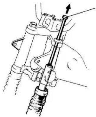
natural_image
Mechanical assembly diagram showing a hand holding a spring-loaded component with an arrow indicating direction (no text or symbols present)Pull up on each front fork into position in the top and bottom fork bridges using a long, 10-mm (pitch 1.5) bolt as shown.
- FRONT FORK
Before disassembly, drain oil from the fork and remove the 37 mm snap ring.
37 mm SNAP RING INSTALLATION
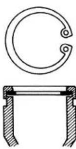
natural_image
Technical drawing of a mechanical component with a circular top and a cross-sectional view (no text or symbols)• Install the ring with the sharp edge end facing up.
FORK SEAL DRIVER
No. 07947-1180001
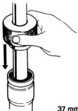
natural_image
Hand holding a mechanical component with a 37 mm scale indicator (no text or symbols on the diagram itself)37 mm SNAP RING OIL SEAL
CAUTION
Use care in assembling to avoid damaging the oil seal.
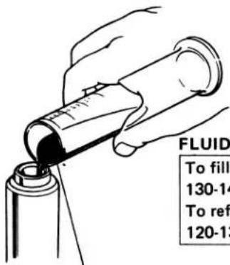
ATF (Automatic Transmission Fluid)
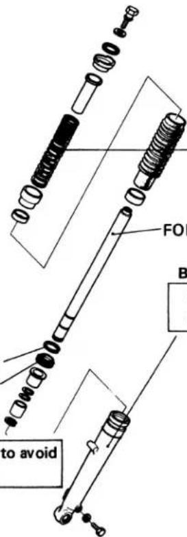
FORK SPRING
Install the spring with the narrow pich end up.
FORK PIPE
BOTTOM CASE
During assembly, be careful to prevent dust and dirt from entering.
NOTE
• After assembly, check for operation and signs of leaks.
- Wipe clean excess fluid from each fork.
• After assembling, check for oil leaks
b. Inspection
- FRONT AXLE BEND
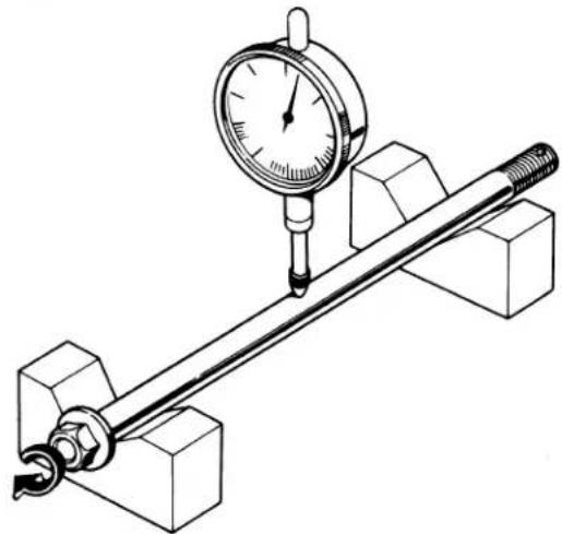
natural_image
Technical illustration of a mechanical measurement setup with a dial indicator and a rod mounted on a base (no text or symbols)| Standard | Service Limit |
| 0-0.05 mm(0-0.002 in.) | 0.2 mm (Replace)(0.008 in.) |
Actual bend is 1/2 of total indicator reading.
• FRONT WHEEL RUNOUTS
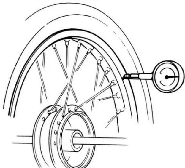
natural_image
Technical line drawing of a bicycle wheel assembly with suspension components (no text or symbols)| Standard | Service Limit | |
| Axial runout | 0-0.5 mm(0-0.02 in.) | 1.0 mm (Replace)(0.04 in.) |
| Radial runout | 0-0.5 mm(0-0.02 in.) | 1.0 mm (Replace)(0.04 in.) |
NOTE
Check the spokes for looseness.
- BRAKE LINING THICKNESS
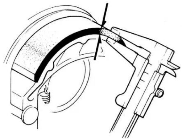
natural_image
Technical line drawing of a mechanical assembly with no visible text or symbols| Standard | Service Limit |
| 4.0 mm(0.16 in.) | 2.0 mm (Replace)(0.08) |
Take least measurement.
- BRAKE DRUM I.D.

natural_image
Illustration of a hand using a tool to lift a mechanical component (no text or symbols visible)| Standard | Service Limit |
| 110.0 mm(4.3307 in.) | 111.0 mm (Replace)(4.3701 in.) |
• FRONT WHEEL BEARING PLAY
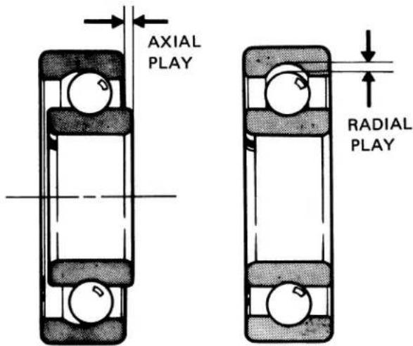
| Standard | Service Limit | |
| Axial play | 0-0.05 mm(0-0.002 in.) | 0.1 mm (Replace)(0.004 in.) |
| Radial play | 0.003-0.008 mm(0.0001-0.0003 in.) | 0.04 mm (Replace)(0.0016 in.) |
• FRONT FORK PIPE INSPECTION
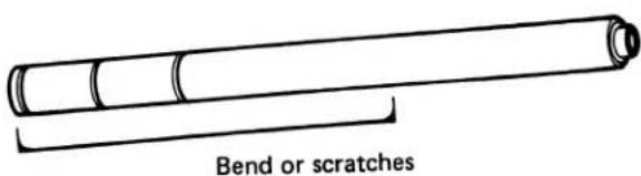
• FRONT FORK PISTON O.D.
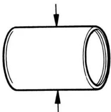
natural_image
Simple line drawing of a cylindrical object with an arrow indicating upward force or direction (no text or symbols)| Standard | Service Limit |
| 30.950-30.975 mm(1.219-1.220 in.) | 30.85 mm (Replace)(1.215 in.) |
• FRONT SUSPENSION SPRING FREE LENGTH
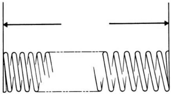
natural_image
Pure diagram of a coiled spring system without any text, numbers, or symbols| Standard | Service Limit |
| 203 mm(8.0 in.) | 185 mm (Replace)(7.3 in.) |
NOTE
The front suspension springs should be installed as a matched set.
• FRONT FORK BOTTOM CASE I.D.
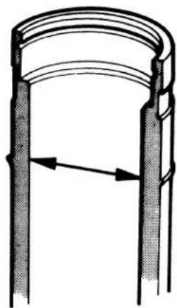
natural_image
Diagram of a cylindrical object with two vertical supports and an arrow indicating direction (no text or symbols)| Standard | Service Limit |
| 31.000-31.039 mm(1.221-1.223 in.) | 31.10 (Replace)(1.225 in.) |
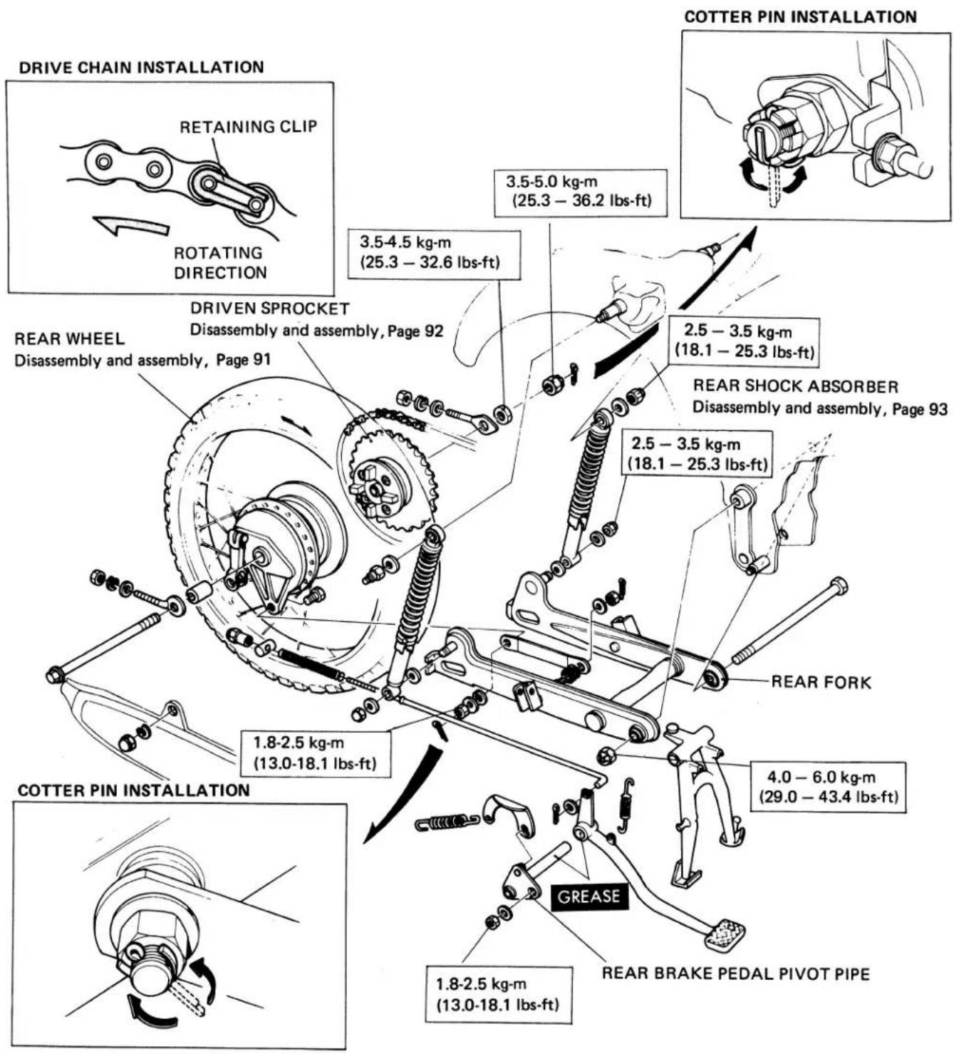
After assembling, perform the following operations:
Brake pedal play adjustment....Page 31
Rear brake stoplight switch adjustment ..... Page 31
Drive chain slack adjustment....Page 32
a. DISASSEMBLY/ASSEMBLY
- REAR WHEEL
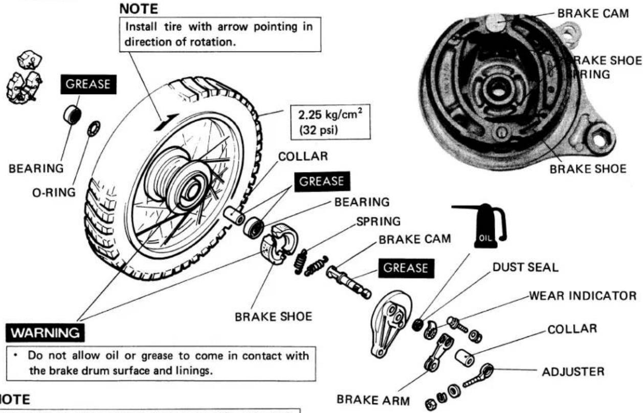
NOTE
The wheel can be removed by removing the axle shaft only (with the sleeve nut left intact) without removing the drive chain.
• DRIVING WHEEL BEARING
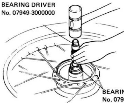
- BRAKE ARM INSTALLATION
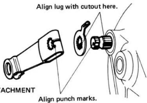
NOTE
-
Drive the bearing squarely, being careful not to allow it to tilt.
• Install the bearing with the shield end outward. -
DRIVEN FLANGE
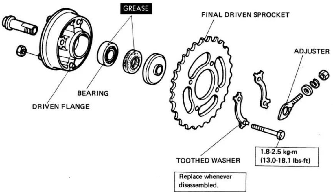
• DRIVING WHEEL BEARING
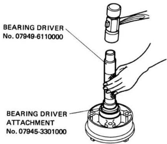
NOTE
Drive the bearing squarely, being careful not to allow it to tilt.
• TOOTHED WASHER INSTALLATION
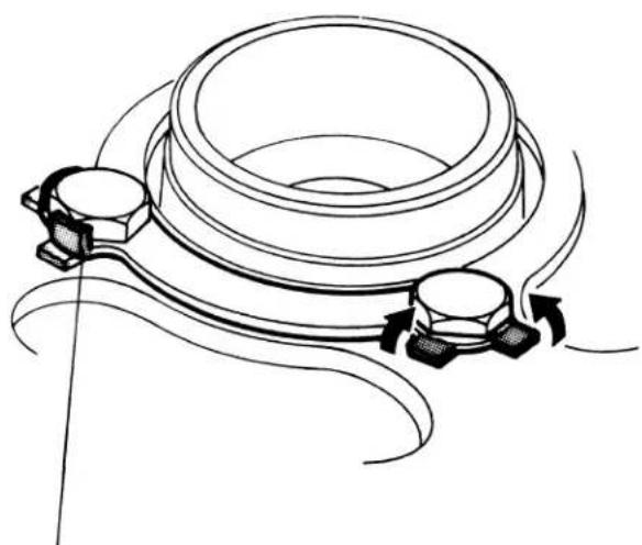
natural_image
Technical line drawing of a mechanical component with rotating parts and curved arms (no text or symbols)NOTE
Bend two tabs against the corresponding sides of head of each bolt.
- REAR SHOCK ABSORBER
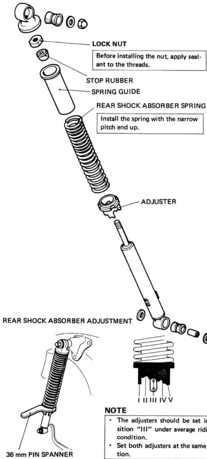
REAR SHOCK ABSORBER SPRING REMOVAL
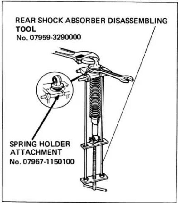
After installation, check the operation of the rear shock absorbers.
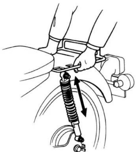
natural_image
Line drawing of a car suspension system with mechanical components and motion arrows (no text or symbols)NOTE
- The adjusters should be set in position "III" under average riding condition.
- Set both adjusters at the same position.
b INSPECTION
- REAR AXLE BEND
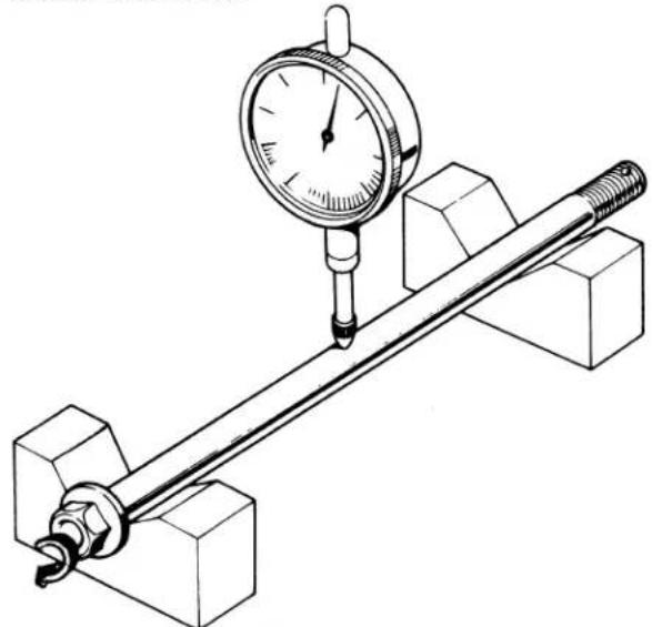
natural_image
Technical line drawing of a mechanical measurement setup with a dial indicator and rod (no text or symbols)| Standard | Service Limit |
| 0-0.05 mm(0-0.002 in) | 0.2 mm (Replace).(0.008 in.) |
Actual bend is 12 of total indicator reading.
- REAR WHEEL RUNOUT
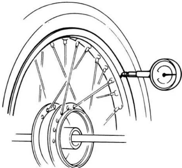
natural_image
Technical line drawing of a bicycle wheel assembly with suspension components (no text or symbols)| Standard | Service Limit | |
| Axial runout | 0-0.5 mm(0.02 in) | 1.0 mm (Replace)(0.04 in) |
| Radial runout | 0-0.5 mm(0.02 in.) | 1.0 mm (Replace)(0.04 in.) |
- BRAKE DRUM I.D.
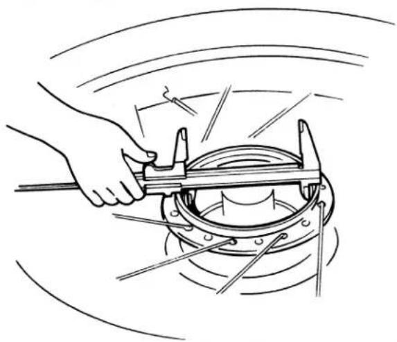
natural_image
Illustration of a hand using a tool to lift a mechanical component (no text or symbols visible)| Standard | Service limit |
| 110.0 mm(4.3307 in.) | 110.0 mm(4.370 in.) |
Check the diameter of the brake drum surface by using a clipper gauge and in two directions at right angles to each other.
- BRAKE LINIG THICKNESS
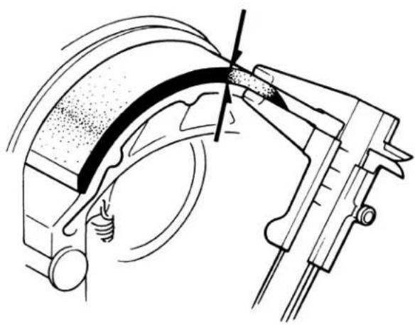
natural_image
Technical line drawing of a mechanical assembly with no visible text or symbols| Standard | Service Limit |
| 4.0 mm(0.16 in.) | 2.0 mm (Replace)(0.08 in.) |
- REAR WHEEL BEARING PLAY
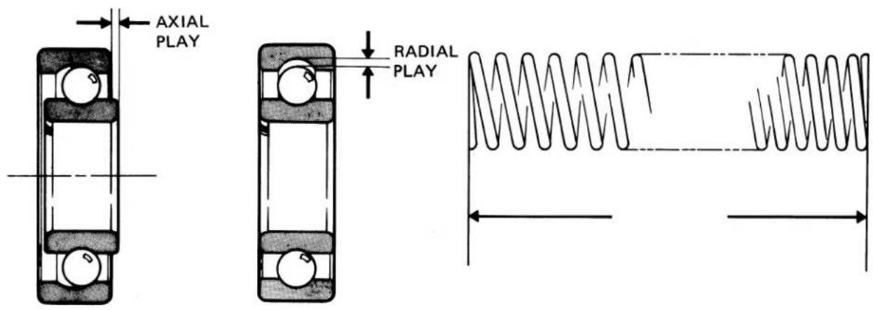
| Standard | Service Limit | |
| Axial play | 0-0.05 mm(0-0.002 in.) | 0.1 mm (Replace)(0.004 in.) |
| Radial play | 0.003-0.018 mm(0.0001-0.0007 in.) | 0.04 mm (Replace)(0.0016 in.) |
| Standard | Service Limit |
| 223 mm(8.78 in.) | 207 mm (Replace)(8.16 in.) |
- REAR SHOCK ABSORBER CHECK
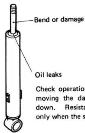
• FINAL DRIVEN SPROCKET CHECK
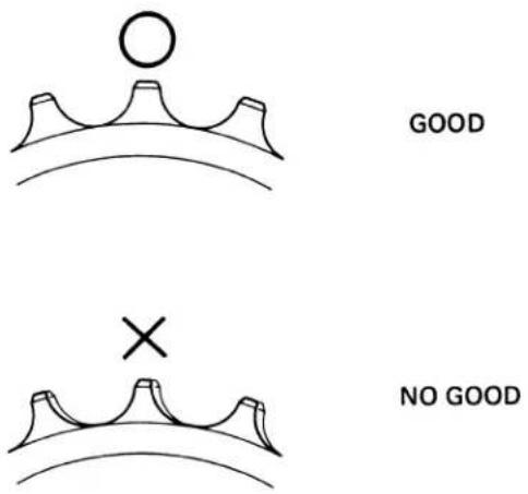
NOTE
Also check the drive chain if the sprocket is worn or damaged.
• TAILLIGHT
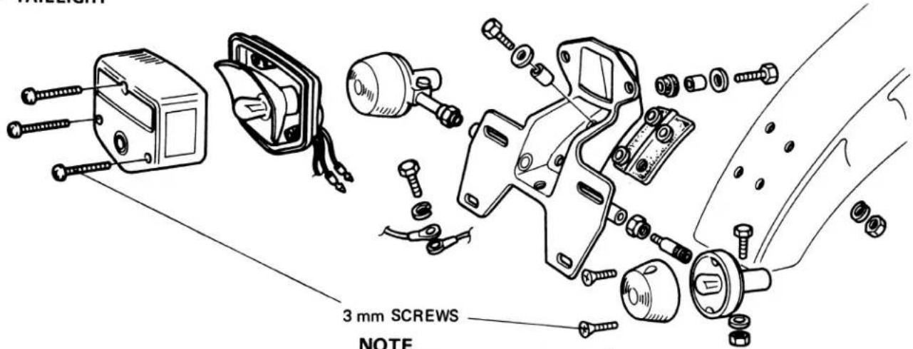
NOTE
Do not over tighten the screws, as over tightening may damage the lens.
- FUEL TANK
WARNING
Do not bring open flames near gasoline. Wipe off spilled gasoline at once.
FUEL TANK
5.5 liters (1.4 US gal; 1.2 Imp. gal); 0.8 liters for reserve (0.2 US gal; 0.18 Imp. gal)
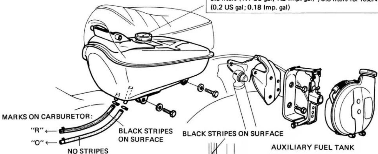
NOTE
• Thoroughly clean the interior of the fuel tank.
- Check the fuel tubes for evidence of cracks or deterioration.
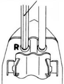
natural_image
Technical diagram of a mechanical assembly with labeled component R (no text or symbols beyond label)2.3 liters (0.6 US gal; 0.54 Imp. gal)
NOTE
Connect the tube with stripes to the "R" fitting on the fuel tank.
- CABLE ROUTING
CAUTION
Route the brake, throttle and speedometer cables as shown.
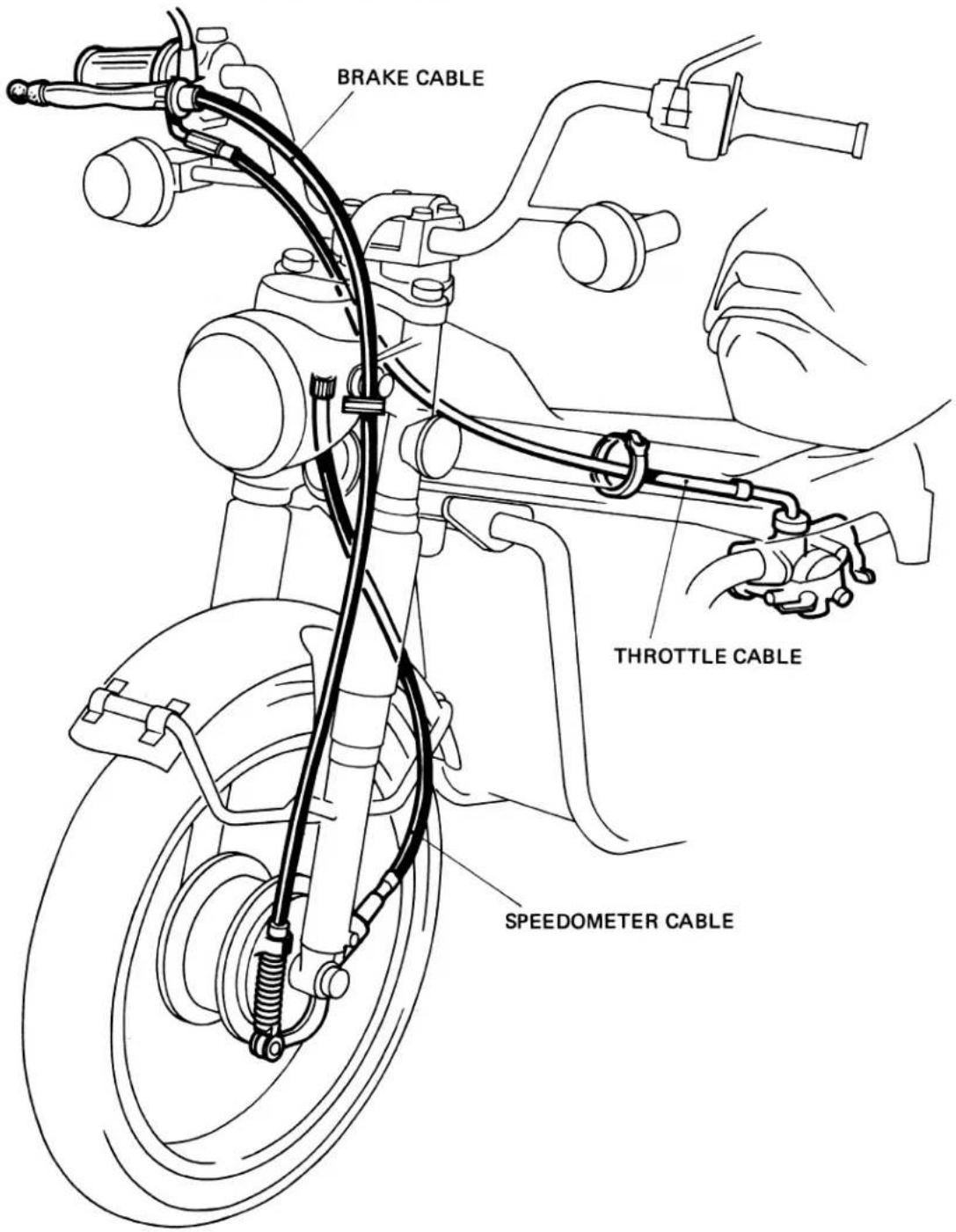
- WIRE HARNESS ROUTING
FRONT BRAKE
STOPLIGHT SWITCH
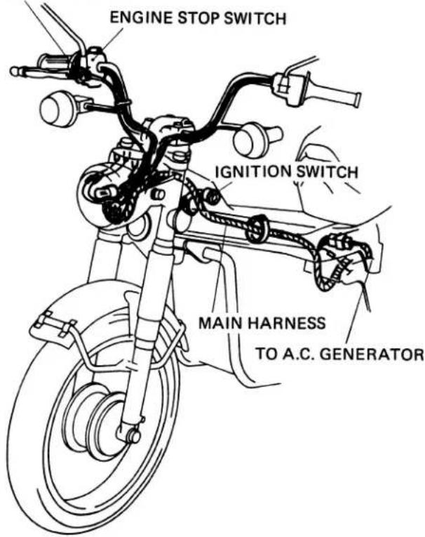
NOTE
Make sure that the battery cable is not pinched between the battery cover and frame.
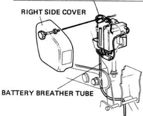
REAR HARNESS
Clamp the harness to the back of the rear fender.
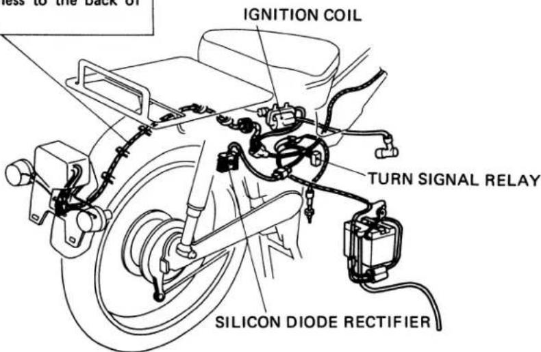
1. BATTERY CHARGING SYSTEM
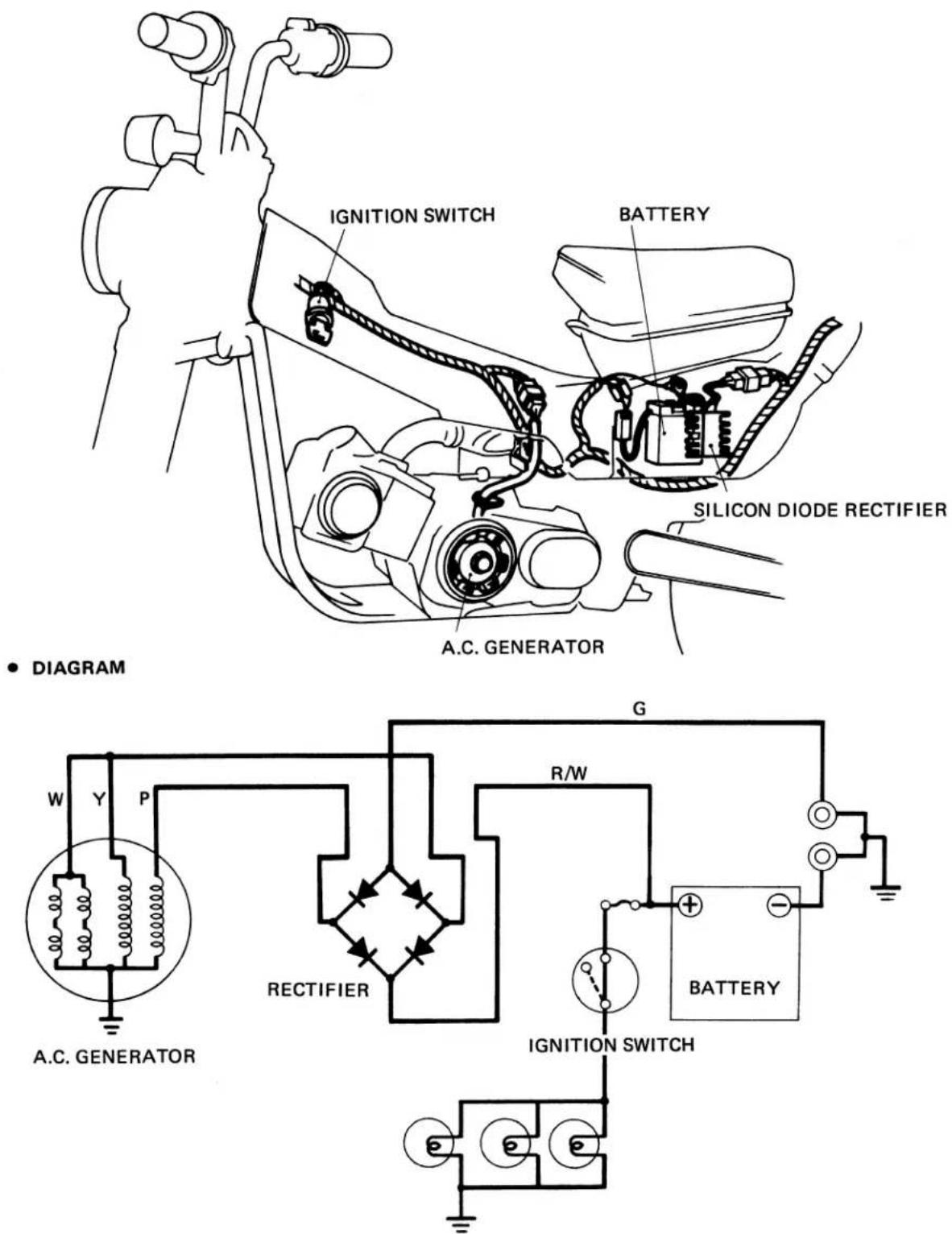
- CHARGING TEST
Connect the tester as shown below and run the engine at the following speeds:
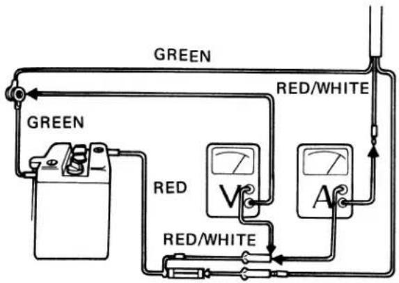
2,800 rpm .... Charging should start (6.8V min.)
5,000 rpm ..... 1A min (7.2V min)
10,000 rpm 3.0A min (8.8V min)
SPECIFIC GRAVITY OF BATTERY ELECTROLYTE :
1.260-1.280 [at 20°C (68°F)]
Raise the engine speed gradually and note the exact current and voltage indicated on the meters. Do not allow the needle of the meter to swing widely beyond the limit of needle travel.
• STATOR COIL CONTINUITY TEST
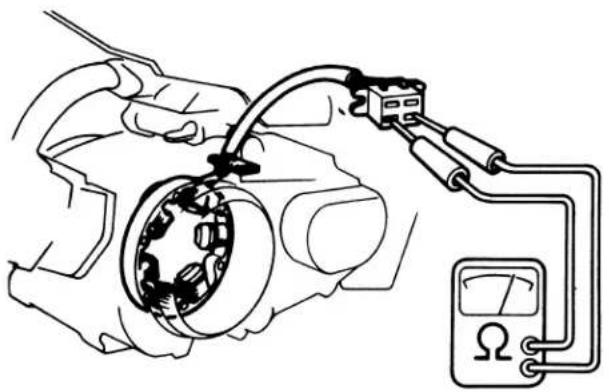
natural_image
Illustration of hands connecting a mechanical device to an analog multimeter (no text or symbols present)| Pink | Yellow | White |
The coil is normal if there is continuity between circuits (o-o).
- RECTIFIER CONTINUITY TEST
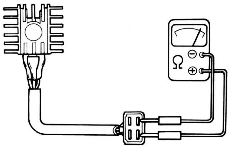
natural_image
Pure electrical circuit lines without any symbolsNOTE
Do not reverse porality.
| Negative (-) terminal\Positive (+) | RED/WHITE | PINK | YELLOW | GREEN |
| RED/WHITE | X | X | X | |
| PINK | 0 | X | X | |
| YELLOW | 0 | X | X | |
| GREEN | 0 | 0 | 0 |
The diode rectifier is normal if there is continuity between the terminals (marked "0"). There should be no continuity between the terminals marked "X".
• BATTERY SERVICE
- Charging Battery
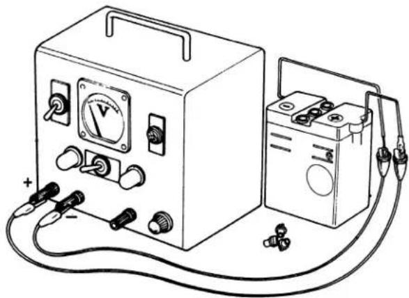
natural_image
Line drawing of a simple electrical testing setup with a voltmeter and battery, no text or symbols present| Hook-up instruction | Connect the positive (+) terminal of the charger to the positive (+) terminal of the battery. Connect the negative (−) terminal of the charger to the negative terminal of the battery. |
| Charging current | 0.5A |
| State of charge of battery | Continue charging until the specific gravity of the battery electrolyte is 1.260 to 1.280 [20°C (68°F)]. |
| Charging time | About 3-15 hours if specific gravity is below 1.220 [20°C (68°F)]. |
WARNING
- Do not allow open flame or cigarettes near the battery while charging.
- Quick charging is not advisable. Stop charging if the temperature of the battery electrolyte is over 45°C (113°F).
Electrolyte Temperature Vs Specific Gravity
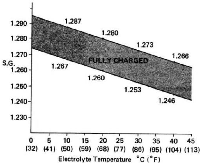
area
| Electrolyte Temperature (°C) | S.G. | |---|---| | 0 | 1.287 | | 10 | 1.280 | | 20 | 1.273 | | 30 | 1.266 | | 40 | 1.266 | | 50 | 1.267 | | 60 | 1.260 | | 70 | 1.253 | | 80 | 1.246 | (32) (32) (41) (50) (59) (68) (77) (86) (95) (104) (113) (113) (113) (113) (113) (113) (113) (113) (113) (113) (113) (113) (113) (113) (113) (113) (113) (113) (113) (113) (114) (114) (114) (114) (114) (114) (114) (114) (114) (114) (114) (114) (114) (114) (114) (114) (114) (114) (114) (114) (115) (115) (115) (115) (115) (115) (115) (115) (115) (115) (115) (115) (115) (115) (115) (115) (115) (1266) (40) (40) (40) (40) (40) (40) (40) (40) (40) (40) (40) (40) (40) (40) (40) (40) (40) (40) (40) (40) (40) (40)- The gravity of electrolyte changes 0.007 for every 10^ temperature.
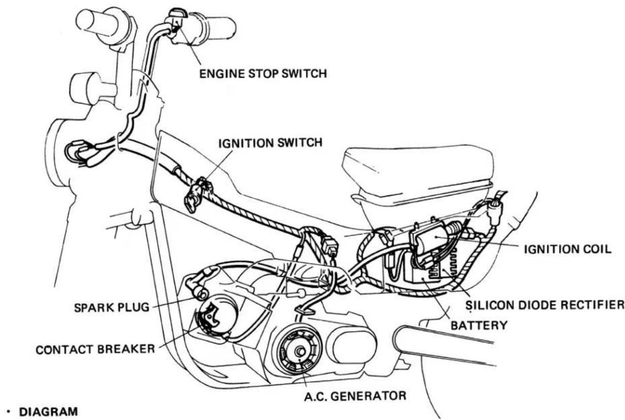
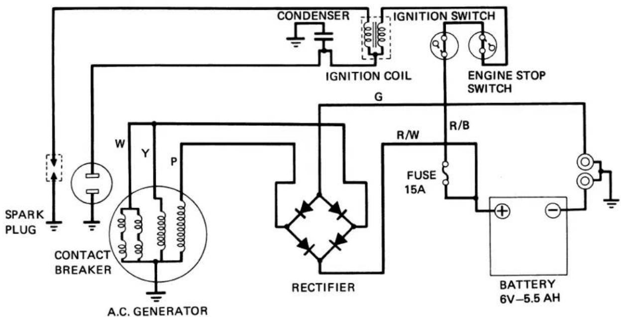
flowchart
graph TD
    A["SPARK PLUG"] --> B["CONTACT BREAKER"]
    B --> C["A.C. GENERATOR"]
    C --> D["IGNITION COIL"]
    D --> E["CONDENSER"]
    E --> F["IGNITION SWITCH"]
    F --> G["ENGINE STOP SWITCH"]
    G --> H["FUSE 15A"]
    H --> I["BATTERY 6V-5.5 AH"]
    I --> J["R/B"]
    J --> K["RECTIFIER"]
    K --> L["R/W"]
    L --> M["G"]
    M --> N["Ground"]
- IGNITION COIL 3-POINT SPARK TEST
Make the connections as described in the booklet furnished with the service tester.
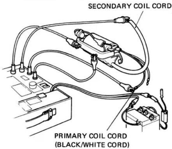
NOTE
• Perform this operation on an insulated surface.
- Keep the aligator clips on the secondary at least 50 mm away from each other.
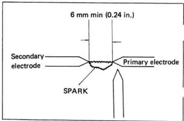
The ignition coil is normal if sparks jump across gap more than 6 mm (0.24 in.) under this test.
• CONDENSER CAPACITY TEST
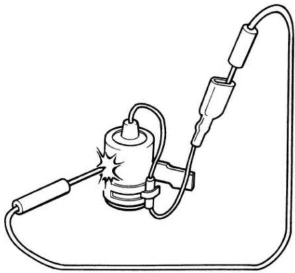
natural_image
Line drawing of a mechanical device with wires and a central component (no text or symbols)- Before making a capacity test, discharge the condenser by touching the positive center lead to any case ground.
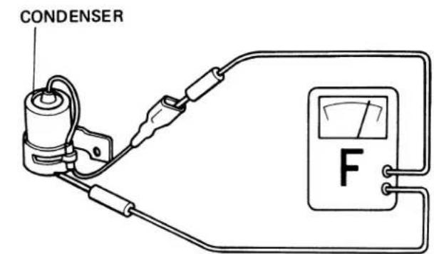
CAPACITY
0.27 - 0.33μF
Perform this operation on an insulated surface.
- IGNITION COIL CONTINUTY TEST
• Continuity between Primary and Secondary Coil Leads
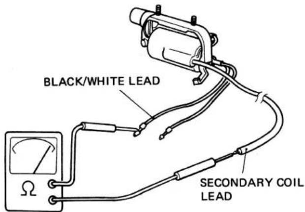
• Continuity between Primary coil Lead and Body Ground
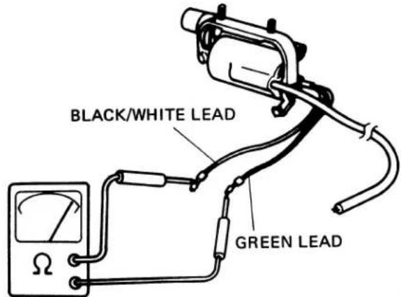
- CONTACT BREAKER POINT INSPECTION
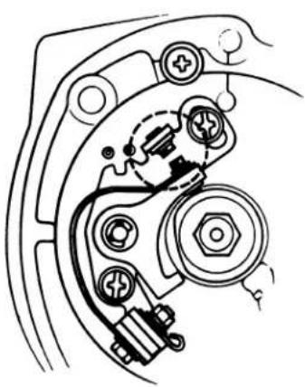
natural_image
Mechanical assembly diagram showing gear and housing components (no text or labels)
GOOD
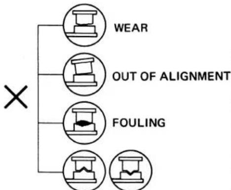
flowchart
graph TD
    A["×"] --> B["WEAR"]
    A --> C["OUT OF ALIGNMENT"]
    A --> D["FOULING"]
METAL TRANSFER
• Continuity between Secondary Coil Lead and Body Ground
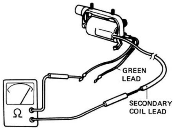
NOTE
Before making a continuity test, remove the noise suppressor cap. To remove, turn the cap in the counterclockwise direction.
The ignition coil is correct if there is continuity in all cases.
For inspection of point gap, see Page 22.
- IGNITION SWITCH
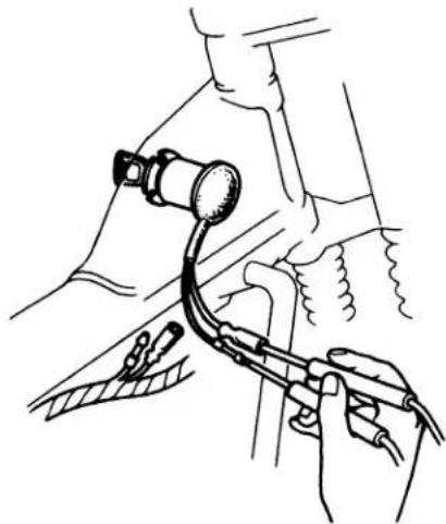
natural_image
Medical illustration showing hands performing a procedure with a catheter and tubing (no text or symbols)- TURN SIGNAL SWITCH
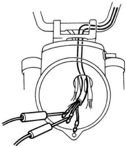
natural_image
Technical line drawing of a mechanical component with wires and connectors (no text or symbols)• HORN SWITCH
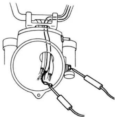
natural_image
Technical line drawing of a mechanical device with hoses and wires (no text or symbols)| switch\wire color | Black | Red/Blue |
The switch is normal if there is continuity between terminals (o-o).
| switch\wire color | Light Blue | Grey | Orange |
The switch is normal if there is continuity between terminals (o-o).
| switch\wire color | Light Green | Frame (ground) |
The switch is normal if there is continuity between terminals (o-o).
● HEAD LIGHT DIMMER SWITCH
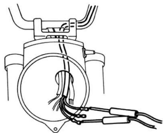
natural_image
Technical line drawing of a mechanical device with wires and connectors (no text or symbols)● ENGINE STOP SWITCH
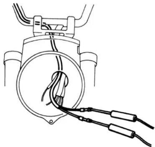
natural_image
Line drawing of a mechanical device with wires and connectors, no text or symbols present• FRONT BRAKE TOPLIGHT SWITCH
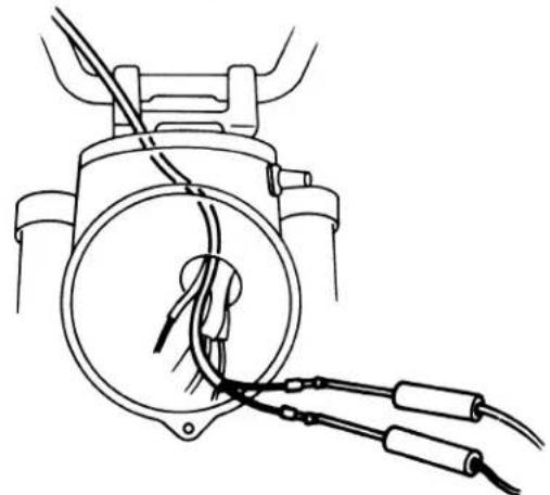
natural_image
Line drawing of a mechanical component with wires and connectors (no text or symbols)| Switch\Wire color | White | Green | Blue |
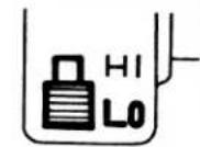 | |||
 |
The switch is normal if there is continuity between terminals (o-o).
| Switch\Wire color | Black | Black White | |
 | OFFRUNOFF | ||
 | OFFRUNOFF | ||
The switch is normal if there is continuity between terminals (o-o).
| Switch\Wire color | Black | Green/Yellow |
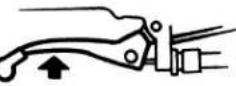 | ||
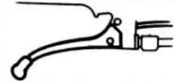 |
The switch is normal if there is continuity between terminals (o-o).
- REAR BRAKE STOPLIGHT SWITCH
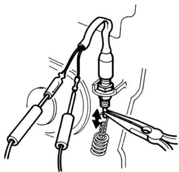
natural_image
Technical diagram of a mechanical assembly with springs and connecting rods (no text or labels)| Switch\Wire color | Black | Green/Yellow |
| PULL | ||
| FREE |
The switch is normal if there is continuity between terminals (O—O).
• HORN
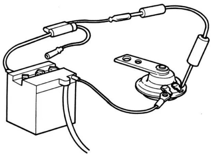
natural_image
Line drawing of a mechanical or electrical device with wires and components, no text or symbols presentINTRODUCTION
This addendum contains mandatory emissions maintenance for CT90's manufactured after December 31, 1977.
Follow the Maintenance Schedule recommendations (Page. 6) to ensure that the vehicle is in peak operating condition and the emission levels are within Federal Clean Air Act Standards. Performing the first scheduled maintenance is very important. It compensates for the initial wear that occurs during break-in.
Refer to the base CT90 Shop Manual for service items not described in this addendum.
ALL INFORMATION, ILLUSTRATIONS, DIRECTIONS AND SPECIFICATIONS INCLUDED IN THIS PUBLICATION ARE BASED ON THE LATEST PRODUCT INFORMATION AVAILABLE AT THE TIME OF APPROVAL FOR PRINTING. HONDA MOTOR CO., LTD. RESERVES THE RIGHT TO MAKE CHANGES AT ANY TIME WITHOUT NOTICE AND WITHOUT INCURRING ANY OBLIGATION WHATEVER.
NO PART OF THIS PUBLICATION MAY BE REPRODUCED WITHOUT WRITTEN PERMISSION.
HONDA MOTOR CO., LTD. Service Publications Office
CONTENTS
- SPECIFICATIONS ..... 110
-
EMISSION CONTROL SYSTEM .....112
-
CONTROL SYSTEM....112
-
EMISSION CONTROL INFORMATION LABEL....113
-
MAINTENANCE SCHEDULE....114
-
MAINTENANCE SCHEDULE....114
-
INSPECTION AND ADJUSTMENT .....115
-
ENGINE OIL....115
- ENGINE OIL FILTER SCREEN .....116
- CRANKCASE BREATHER.....117
- AIR CLEANER .....117
- FUEL LINES .....118
- SPARK PLUG 118
- VALVE CLEARANCE....119
- CONTACT BREAKER POINTS .....119
- IGNITION TIMING....120
- SPARK ADVANCER 121
- CAM CHAIN TENSION 121
- THROTTLE OPERATION 122
- CARBURETOR IDLE SPEED....122
- CARBURETOR CHOKE 122
- DRIVE CHAIN....123
- BATTERY....124
- BRAKE SHOE WEAR ..... 125
- BRAKE SYSTEM ..... 125
- STOP LIGHT SWITCH....127
- HEADLIGHT AIM 127
- CLUTCH FREE PLAY 128
- SIDE STAND....128
- SUSPENSION....128
- SPARK ARRESTER 129
- NUTS, BOLTS, FASTENERS ..... 130
- WHEELS....130
-
STEERING HEAD BEARING....131
-
CARBURETOR .....132
-
CARBURETOR SPECIFICATIONS .....132
- DISASSEMBLY AND ASSEMBLY.....132
- PILOT SCREW INITIAL SETTING .....132
- PILOT SCREW ADJUSTMENT .....133
-
HIGH ALTITUDE ADJUSTMENT.....133
-
BREATHER SYSTEM....134
-
TROUBLESHOOTING.....135
| Item | Metric | English | |
| DIMENSIONS | |||
| Overall length | 1870 mm | 73.6 in | |
| Overall width | 740 mm | 29.1 in | |
| Overall height | 1060 mm | 41.7 in | |
| Wheel base | 1220 mm | 48.0 in | |
| Seat height | 775 mm | 30.5 in | |
| Ground clearance | 165 mm | 6.5 in | |
| Dry weight | 90 kg | 198.5 lb | |
| FRAME | |||
| Type | Back bone | ||
| Front suspension, travel | Telescopic fork, 102 mm (4.0 in) | ||
| Rear suspension, travel | Swing arm, 77 mm (3.0 in) | ||
| Front tire size, type | 2.75-17-4PR Knobby, (Tire air pressure: 1.75 kg/cm2·25 psi) | ||
| Rear tire size, type | 2.75-17-4PR Knobby, (Tire air pressure: 2.25 kg/cm2·32 psi) | ||
| Front brake | Internal expanding shoes | ||
| Rear brake | Internal expanding shoes | ||
| Fuel capacity | 5.5 lit. | 1.4 US. gal. | |
| Fuel reserve capacity | 0.8 lit. | 0.2 US. gal. | |
| Auxiliary fuel tank capacity | 2.3 lit. | 0.6 US. gal. | |
| Caster angle | 63° | ||
| Trail length | 75 mm | 3 in | |
| Front fork oil capacity To fill dry fork assy. 130-140 cc | 4.4-4.7 US oz. | ||
| To refill after draining 120-130 cc | 4.1-4.4 US oz. | ||
| ENGINE | |||
| Type | Air cooled 4-stroke O.H.C. engine | ||
| Cylinder arrangement | Single cylinder 75° inclined from vertical | ||
| Bore and stroke | 50 x 45.6 mm | 1.970 x 1.797 in | |
| Displacement | 89.5 cc | 5.46 cu in | |
| Compression ratio | 8.2 : 1 | ||
| Compression pressure | 12 kg/cm2(1000~1200 rpm) | 170 psi (1000~1200 rpm) | |
| Carburetor, venturi dia. | Piston valve type, 16 mm (0.64 in) | ||
| Valve train | Chain driven over head camshaft | ||
| Oil capacity | 0.9 lit | 0.95 US qt | |
| Lubrication system | Forced pressure and wet sump | ||
| Fuel required | All gasoline of 91 research octane (86 pump octane) or higher | ||
| Air filtration | Oiled polyurethane foam filter | ||
| Valve timing IN Opens | 5° BTDC (at 1mm lift) 58° BTDC (at 0 lift) | ||
| Closes | 20° ABDC (at 1 mm lift) 73° ABDC (at 0 lift) | ||
| EX Opens | 25° BBDC (at 1 mm lift) 74° BBDC (at 0 lift) | ||
| Closes | 5° ATDC (at 1 mm lift) 65° ATDC (at 0 lift) | ||
| Item | Metric | English | ||
| Valve clearance IN/EXEngine dry weightIdle speed | 0.05 mm24 kg1300 ± 100 rpm | 0.002 in53 lb | ||
| DRIVE TRAINClutchTransmissionPrimary reductionGear ratio IIIIIIIVAuxiliary transmission High/LowFinal reductionGear shift pattern | Wet multi-plate semi-automatic4-speed constant mesh3.7222.5381.6111.1900.9581.000/1.8673.000, 15/45Left foot operated return system | |||
| ELECTRICALIgnitionIgnition advance "F" markFull advance markRPM from "F" to max. advanceStarting systemAlternatorBattery capacityFuse capacitySpark plug | Battery and ignition coil10° BTDC, Static and idle speed36°-42° BTDC1950-4800 rpmKick starterAC. generator, 0.062 kw/6000 rpm6 V - 5.5 AH15 A | |||
| UsageBrand | For cold climate (below 5°C, 41°F) | Standard | For extended high speed operation | |
| NGKND | D6HAX20FS-U | D8HAX24FS-U | D8HAX24FS-U | |
| 0.27-0.33μF | ||||
| CARBURETORIdentification numberMain jetJet needle markFloat heightPilot screw | Standard2,000m (6,500 ft) max. | High altitude1,500m (5,000 ft) min. | ||
| PB28A# 6518A10.7mm (0.43 in)See page 24 ~ 25. | ←# 60←←← | |||
1. CONTROL SYSTEM (U.S.A.only)
The CT90 is equipped with two Separate Emission Control Systems.
*Exhaust Emission Control System
The exhaust emission control system is composed of a factory pre-set carburetor. No adjustment should be made except to the idle speed with the throttle stop screw.
* Crankcase Emission Control System
The engine is equipped with a "Closed System" to prevent crankcase emissions from entering the atmosphere. Blow-by gas is returned to the combustion chamber through the air cleaner and carburetor.
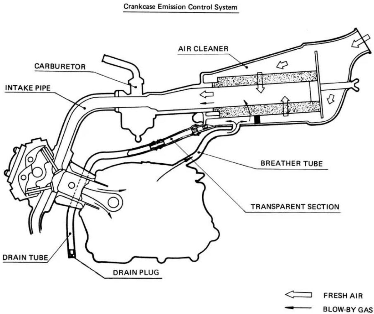
2. EMISSION CONTROL INFORMATION LABEL (U.S.A. only)
CT90's manufactured after December 31, 1977 have an Emission Control Information Label on the frame as shown. It contains basic tune-up specifications for CT90's manufactured after December 31, 1977. Refer to the Shop Manual for more details.
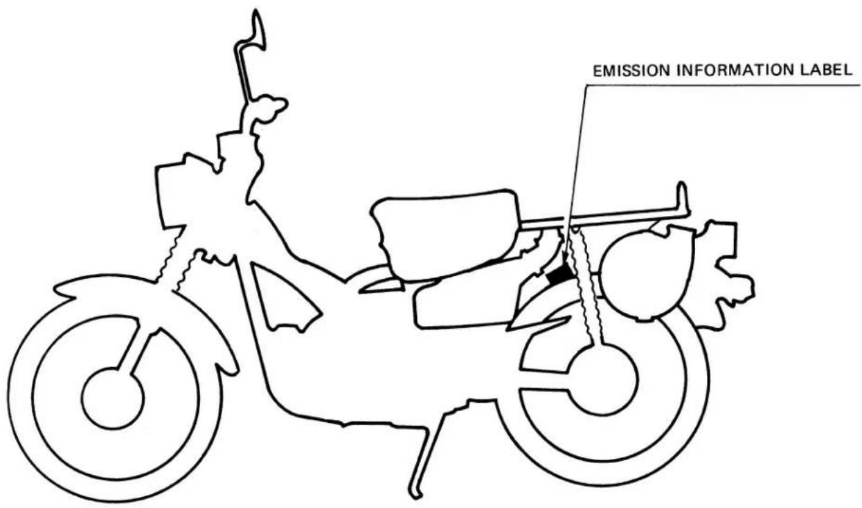
Perform the PRE-RIDE INSPECTION in the Owner's Manual at each maintenance period.
I: Inspect, Clean, Adjust, Lubricate or Replace if necessary.
C: Clean
R: Replace
A: Adjust
| ITEM\FREQUENCY | WHICHEVER OCCURSFIRST →↓ | ODOMETER READINGNOTE (4) | Refer to | ||||
| 600mi.(1000km) | 2400mi.(4000km) | 4800mi.(8000km) | 7200mi.(12000km) | ||||
| EVERY | |||||||
| EMISSION RELATED ITEMS | ENGINE OIL | YEAR | R | REPLACE EVERY1200mi. (2000km) | Page 7 | ||
| * ENGINE OIL FILTER SCREEN | C | Page 8 | |||||
| CRANKCASE BREATHER NOTE (1) | C | C | C | Page 9 | |||
| AIR CLEANER NOTE (2) | C | C | C | Page 9 | |||
| * FUEL LINES | I | I | I | Page 10 | |||
| SPARK PLUG | I | I | R | Page 10 | |||
| * VALVE CLEARANCE | I | I | I | I | Page 11 | ||
| * CONTACT BREAKER POINTS | I | I | I | I | Page 11 | ||
| * IGNITION TIMING | I | I | I | I | Page 12 | ||
| * CAM CHAIN TENSION | A | A | A | A | Page 13 | ||
| * THROTTLE OPERATION | I | I | I | I | Page 14 | ||
| * CARBURETOR IDLE SPEED | I | I | I | I | Page 14 | ||
| * CARBURETOR CHOKE | I | I | I | Page 14 | |||
| NON-EMISSION RELATED ITEMS | DRIVE CHAIN NOTE (3) | I EVERY 600mi. (1000km) | Page 15 | ||||
| BATTERY | MONTH | I | I | I | I | Page 16 | |
| BRAKE SHOE WEAR | I | I | I | Page 17 | |||
| BRAKE SYSTEM | I | I | I | I | Page 17 | ||
| * STOP LIGHT SWITCH | I | I | I | I | Page 19 | ||
| * HEADLIGHT AIM | I | I | I | I | Page 19 | ||
| CLUTCH FREE PLAY | I | I | I | I | Page 20 | ||
| SIDE STAND | I | I | I | Page 20 | |||
| * SUSPENSION | I | I | I | I | Page 20 | ||
| * SPARK ARRESTER | C | C | C | Page 21 | |||
| * NUTS, BOLTS, FASTENERS | I | I | I | I | Page 22 | ||
| ** WHEELS | I | I | I | I | Page 22 | ||
| ** STEERING HEAD BEARING | I | I | Page 23 | ||||
* Should be serviced by an authorized HONDA dealer, unless the owner has proper tools and service data and is mechanically qualified.
** In the interest of safety, we recommend these items be serviced ONLY by an authorized HONDA dealer. NOTE:
(1) More frequent service may be required when riding in rain or at full throttle openings. (U.S.A. only)
(2) More frequent service may be required when riding in dusty areas.
(3) Initial service period 200 miles (300km).
(4) For higher odometer readings, repeat at the frequency interval established here.
1. ENGINE OIL
• ENGINE OIL LEVEL CHECK
- Place the vehicle on its center stand, and remove the oil filler cap/dipstick and wipe it clean.
- Reinsert the dipstick and check the oil level.
NOTE
Do not screw in the dipstick when making this check.
- If the oil level is below the lower level mark, fill to the upper level mark with the recommended oil.
• ENGINE OIL CHANGE
- Remove oil filler cap and drain plug after the engine is warm, and drain the oil.
- Install the drain plug, and check the sealing washer condition. dition.
TORQUE: 2.0–3.5 kg·m (14.5–25.3 ft·lbs)
- Fill crankcase with the recommended oil.
OIL CAPACITY: 0.9 lit. (0.95 US.qt.) approximately.
RECOMMENDED OIL:
Use HONDA 4-STROKE OIL or equivalent.
API SERVICE CLASSIFICATION: SE VISCOSITY:
General, all temperatures; SAE 10W–40 Alternate;
| Above 15°C/59°F | SAE 30 |
| 0°C/32°F - 15°C/59°F | SAE 20 or SAE 20W |
| Below 0°C/32°F | SAE 10W |
- Reinstall the oil filler cap.
- Start the engine and allow it to idle for 2-3 minutes.
- Stop the engine, and make sure that the oil level is at the upper level mark with the vehicle in an upright position, and that there are no oil leaks.
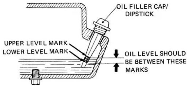
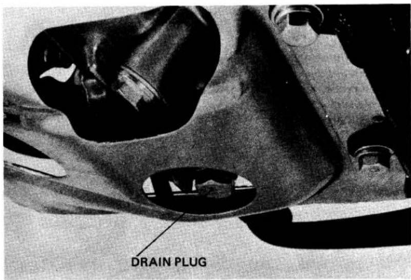
OIL SPECIFICATION
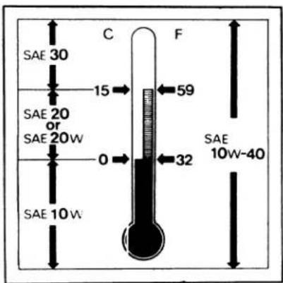
2. ENGINE OIL FILTER SCREEN
NOTE
Perform this maintenance before filling the engine with oil.
- Warm up the engine.
-
Remove the oil filler cap and drain plug and drain the oil.
Turn the fuel valve "OFF". Loosen the carburetor drain plug and drain gasoline from the float bowel. -
Remove the kick starter pedal and foot peg, and loosen four bolts on crankcase protector.
- Remove the right crankcase cover.
- Remove and clean the oil filter screen.
- Reinstall the oil filter screen and right crankcase cover.
-
Reinstall the foot peg.
-
Reinstall the kick starter pedal.
- Retighten four lock bolts on the crank-case protector.
- Fill the crankcase with the recommended engine oil, and start the engine.
- Stop the engine, check the oil level and for oil leaks.

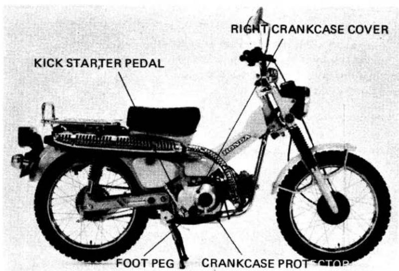
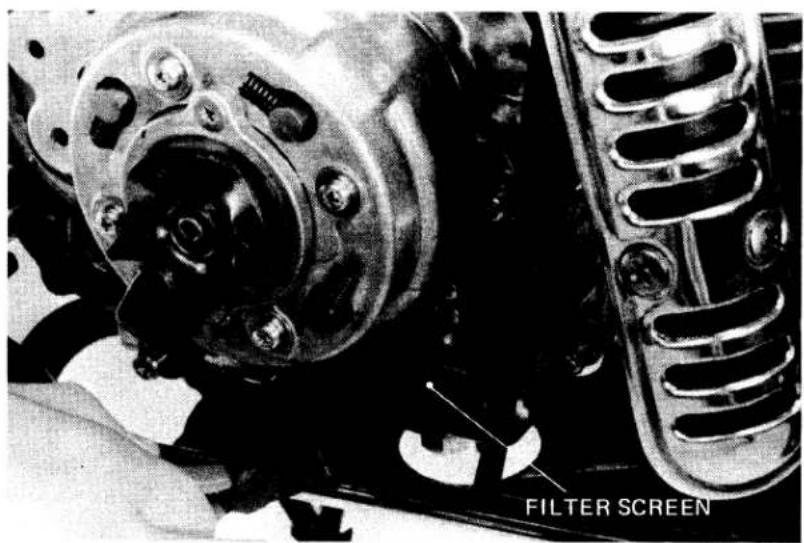
3. CRANKCASE BREATHER (U.S.A.only)
- Remove the drain plug from the drain tube, and drain deposits.
- Reinstall the drain plug.
NOTE
Service more frequently when driven in rain or at full throttle openings, or if deposit level can be seen in the transparent section of drain tube.
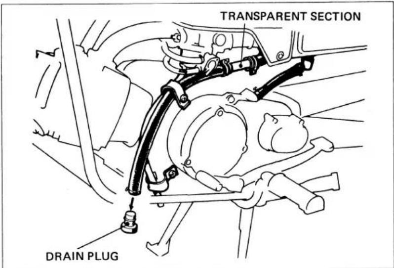
4. AIR CLEANER
- Remove the air cleaner connecting tube and cover.
- Remove the air cleaner cover stud, element cap, and air cleaner element.
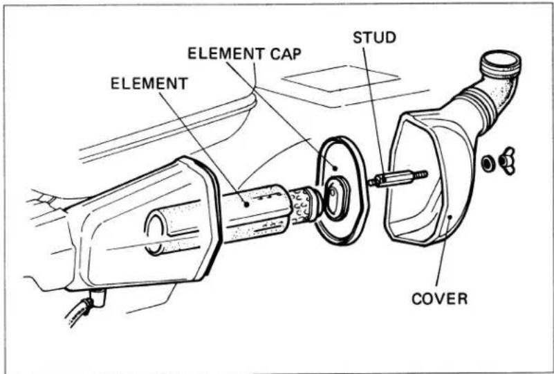
- Wash the air cleaner element in non-flammable or high flash point solvent and allow to dry.
- Soak the air cleaner element in gear oil (#80 - #90), and squeeze out excess.
- Reinstall the air cleaner element.
- Reinstall the cap and air cleaner cover stud.
- Reinstall the air cleaner case cover and air cleaner connecting tube.
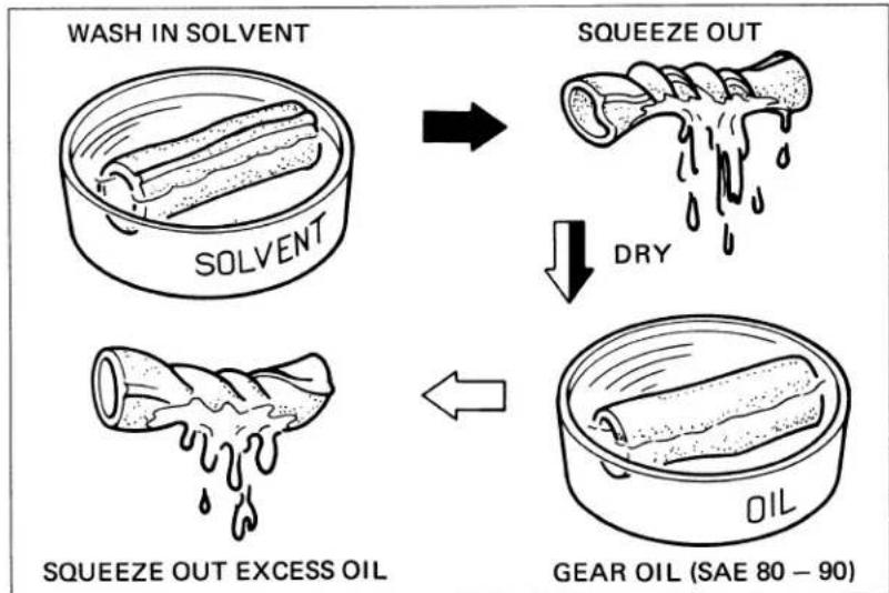
flowchart
graph TD
    A["WASH IN SOLVENT"] --> B["SQUEEZE OUT"]
    B --> C["DRY"]
    C --> D["SQUEEZE OUT EXCESS OIL"]
    D --> E["GEAR OIL (SAE 80 – 90)"]
5. FUEL LINES
Replace any parts which show signs of deterioration, damage or leakage.
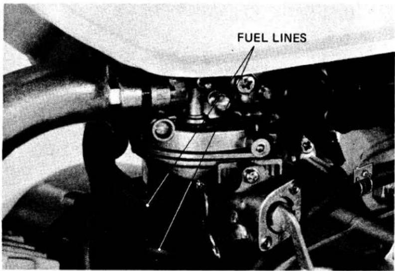
6. SPARK PLUG
- Disconnect the spark plug cap, and remove spark plug.
- Visually inspect the spark plug electrodes for wear.
The center electrode should have square edges and the side electrode should have a constant thickness. Discard the spark plug if there is apparent wear or if the insulator is cracked or chipped. If the spark plug deposits can be removed by sandblasting it can be reused.
| Spark Plugs VS Operating Conditions | |||
| Brand\Usage | For cold climate (below 5°C, 41°F) | Standard | For extended high speed driving |
| NGK | D6HA | D8HA | D8HA |
| ND | X20FS-U | X24FS-U | X24FS-U |
- Use a feeler gauge to make sure the spark plug gap is 0.6–0.7mm (0.024–0.028 in). Adjust by bending the side electrode.
- Reinstall the spark plug and reconnect the spark plug cap.
NOTE
First turn the spark plug finger tight, then tighten' with a spark plug wrench.
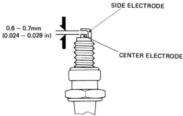
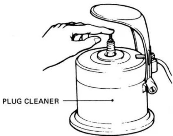
7. VALVE CLEARANCE
NOTE
Valve clearance adjustment must be performed while the engine is cold. (below 35^ C, 95^ F)
- Remove the generator cover and valve adjusting caps.
- Rotate the rotor counterclockwise, and align the "T" mark on the rotor with the index mark on the stator. The piston must be at T.D.C. of the compression stroke.
- Measure the intake and exhaust valve clearances with a 0.05mm (0.002 in) feeler gauge. Insert the feeler gauge between the valve adjusting screw and valve stem.
- Adjust by loosening the valve adjusting screw lock nut and turning the adjusting screw until there is a slight drag on the feeler gauge.
- Hold the adjusting screw and tighten the lock nut.
- Recheck the clearance.
- Reinstall the generator cover and valve adjusting caps.
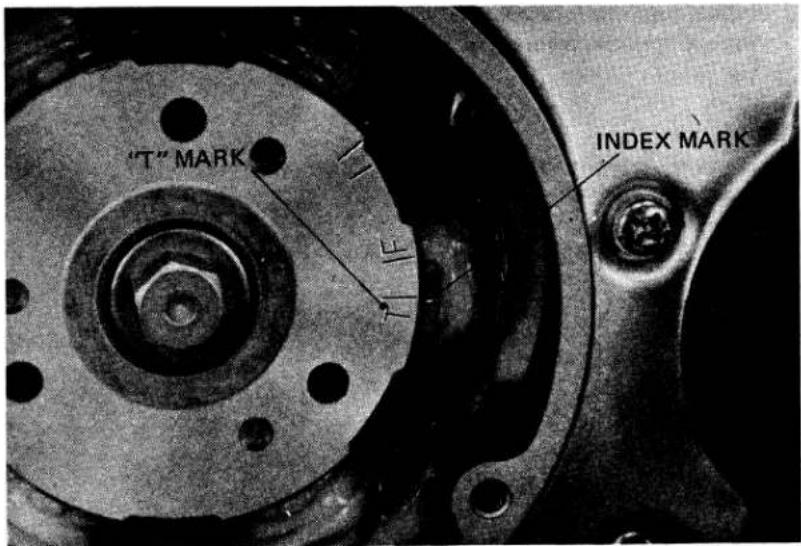
VALVE ADJUSTING WRENCH
No. 07908-0010000
VALVE CLEARANCE (IN/EX): 0.05mm (0.002 in)
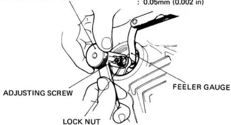
8. CONTACT BREAKER POINTS
- Remove the generator and point covers.
- Clean the point contact surfaces with an electrical contact cleaner to remove any oil film or dirt. If the contact surfaces are level but grayish in color or are slightly pitted, file them lightly with a point file. If the points have a noticeable transfer of metal from one surface to the other, have evidence of heavy arcing, or are worn at an angle, they should be replaced.
CORRECT
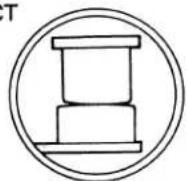
PITTED
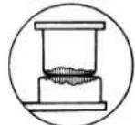
REPAIR OR REPLACE
ONE SIDE CONTACT

BURNED
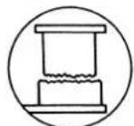
BADLY WORN


REPLACE
- Rotate the rotor countercockwise, and measure the maximum point gap with a fleer gauge.
POINT GAP: 0.3–0.4 mm (0.012–0.016 in) - Adjust by loosening two contact breaker plate locking screws and moving the contact breaker plate.
- Retighten the locking screws and recheck the point gap.
9. IGNITION TIMING ADJUSTMENT
NOTE
Adjust the contact breaker point gap before adjusting ignition timing.
- STATIC TIMING
- Obtain a fully charged 6V battery and a continuity light (6V-3W).
- Connect one lead of the continuity light to the contact breaker terminal, and the other lead to the battery positive (+) terminal.
- Ground the battery negative (—) terminal to the frame.
NOTE
This check can also be made using the battery on the vehicle; make sure that the ignition switch is ON.
-
Rotate the rotor counterclockwise and align the "F" mark on the rotor with the index mark on stator. The timing is correct if the light goes out when both marks align.
-
If the timing is advanced, adjust by loosening the contact breaker locking screws and rotate the base plate counterclockwise.
If the timing is retarded, rotate the base plate clockwise.
Retighten the locking screws and recheck the timing.
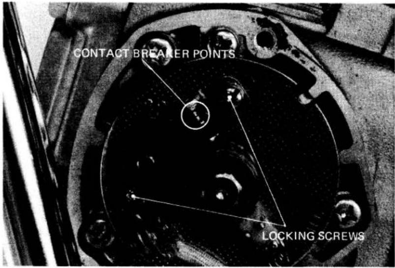
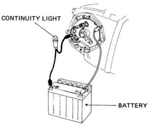
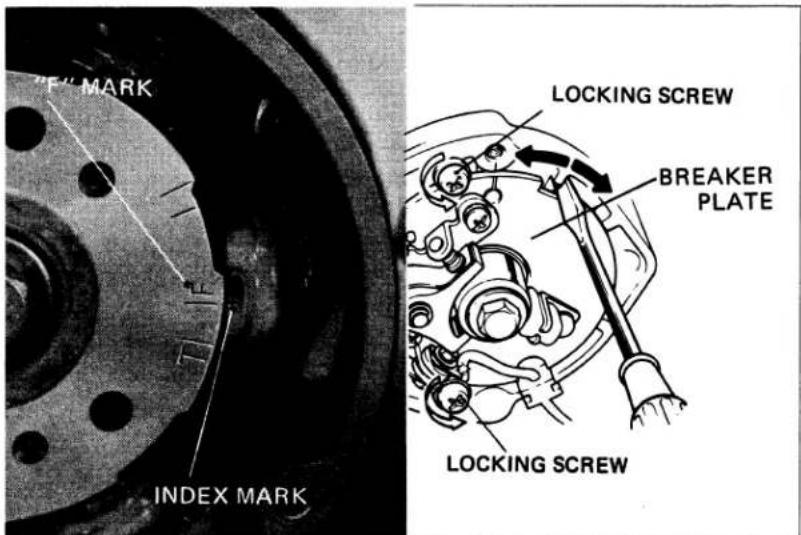
• DYNAMIC TIMING
- Connect a tachometer and a stroboscopic timing light.
- Start the engine and adjust the idle in neutral to 1,300 ± 100 rpm.
- The timing is correct, if the "F" mark on the rotor aligns with the index mark on the stator.
- If necessary, adjust the timing as described for use with a continuity light step 5.
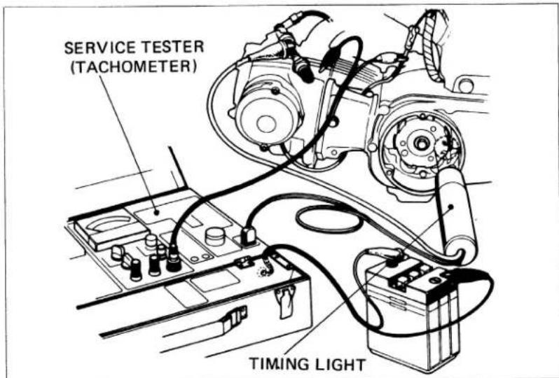
10. SPARK ADVANCER
NOTE
Before performing this test, check and adjust the ignition timing.
- Connect a tachometer and a timing light.
- Start the engine.
- Make sure the index mark on the stator is between the full-advance marks on the rotor at 4,800 rpm.
- If not, check the spark advancer operation.
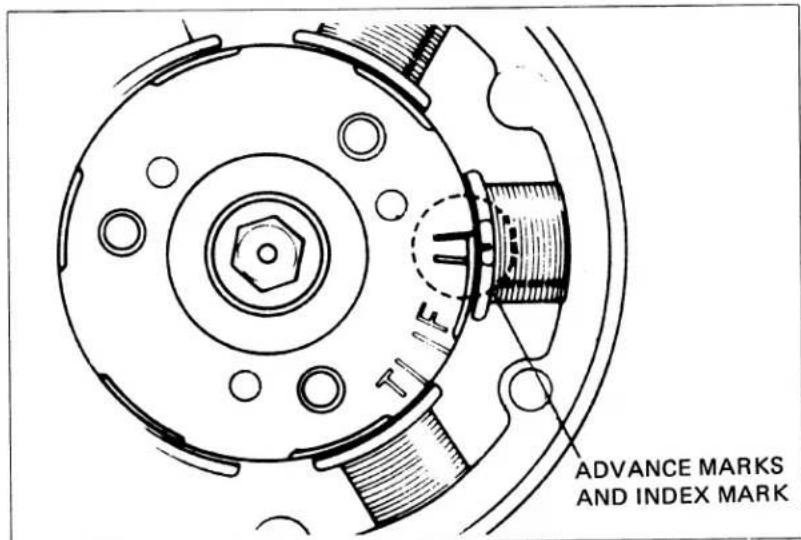
11. CAM CHAIN TENSION
- Start the engine and allow it to idle.
- Loosen the cam chain tensioner lock nut and tensioner adjusting bolt A.
- When adjusting bolt A is loosened, the tensioner will automatically position itself to provide the correct tension.
- Retighten adjusting bolt A and lock nut.
TORQUE: 0.9–1.4 kg-m (6.5–10.0 ft-lbs) NOTE
If the chain is still noisy, remove tensioner plug and screw in adjusting bolt B gradually until cam chain is no longer noisy.
After adjustment, tighten the lock bolt, lock nut and plug.
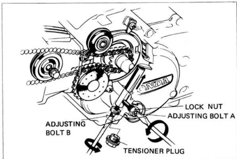
12. THROTTLE OPERATION
- Check that there is no deterioration, damage or kinks in the throttle cable, and that the throttle grip free play is 2–6 mm (1/8–1/4 in) at the throttle grip outer flange.
- Check for smooth throttle grip rotation. Check that the throttle grip returns automatically from the fully open to the fully closed position when released. Check in all steering positions.
- Adjust with either the upper or lower cable adjuster, or replace if necessary. Tighten the lock nuts.
NOTE
Install rubber cap securely after adjustment.
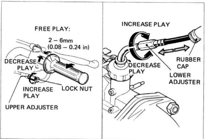
13. CARBURETOR IDLE SPEED
NOTE
The engine must be warm for accurate idle adjustment. Ten minutes of stop and go driving is sufficient.
- Place the vehicle on its center stand. Warm up the engine and determine if the engine idle speed is 1,300 ± 100 rpm with the transmission in neutral.
- Adjust the idle speed with the throttle stop screw.
NOTE
The pilot screw is factory pre-set. Do not adjust the pilot screw except after overhauling the carburetor or if a high altitude main jet is installed (See page 25.).
14. CARBURETOR CHOKE
- Disconnect the air cleaner tube from the carburetor.
- Check the choke lever for smooth operation and that the choke plate opens and closes folly. Inspect the choke plate for damage.
- Reinstall the carburetor and connect the air cleaner tube.
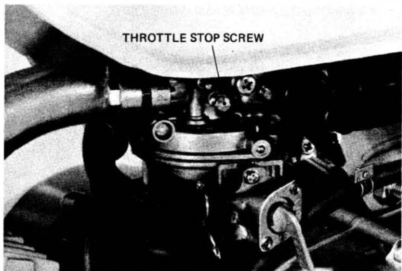
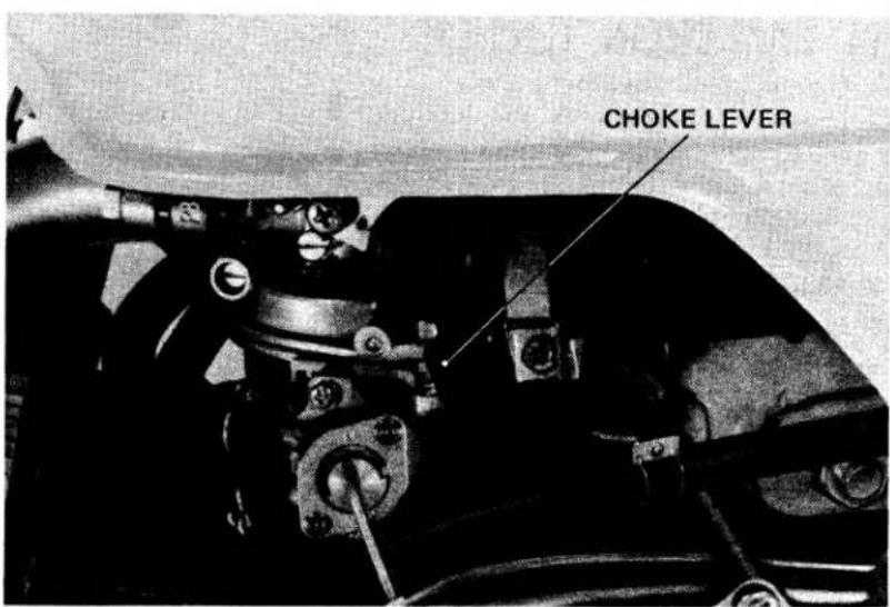
15. DRIVE CHAIN
NOTE
Perform this maintenance with the ignition switch off.
- DRIVE CHAIN FREE PLAY
- Place the vehicle on its center stand and shift the transmission into neutral.
- Measure the drive chain free play midway between the sprockets on the lower chain run.
FREE PLAY : 15–25 mm (5/8–1 in)
- ADJUSTMENT
- Remove the cotter pin from rear axle nut, and loosen the nut.
- Turn nuts on both adjusters as required until the correct drive chain free play is obtained.
NOTE
Be sure that the index mark aligns with the same graduation of the scale on both sides.
- Tighten the axle nut and install a new cotter pin.
TORQUE : 3.5–5.0 kg-m (26–36 ft-lbs)
- Lubricate the drive chain.
• CLEANING / LUBRICATION
When the drive chain becomes extremely dirty, it should be removed and cleaned prior to lubrication.
Remove the master link retaining clip.
NOTE
Do not bend or twist the clip.
Remove the master link. Remove the drive chain. Clean the drive chain with non-flammable or high flash point solvent and brush and allow to dry. Inspect the drive chain for possible wear or damage. Replace any chain that is damaged or excessively worn. Inspect the sprocket teeth for excessive wear or damage. Replace if necessary.
NOTE
Never install a new drive chain on worn sprockets or a worn chain on new sprockets. Both chain and sprockets must be in good condition, or the new replacement chain or sprockets will wear rapidly.
Commercial aerosol type drive chain lubricants are recommended.
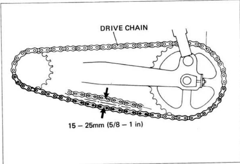
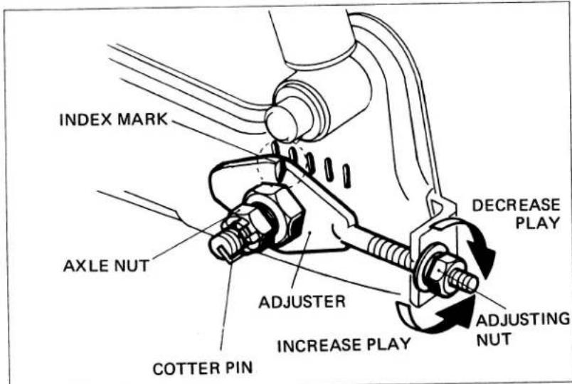
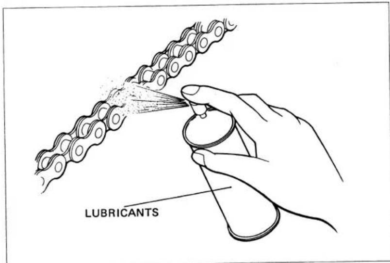
Lubricate the drive chain. Saturate each chain link joint. Install the drive chain and master link. Install the master link retaining clip so that the closed end faces the direction of forward wheel rotation. Master links are reusable, if they remain in excellent condition, but it is recommended that a new master link be installed whenever the drive chain is reassembled. Adjust the drive chain. (See page 15.)
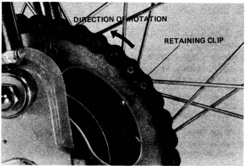
16. BATTERY
- Remove the right side cover.
- Remove the battery band bolt and remove the battery.
- Check the fluid level. Add distilled water to the upper level mark. The electrolyte level must be maintained between the upper and lower level marks.
- If sulfation forms or sediments (paste) accumulate on the bottom, replace the battery.
NOTE
Add distilled water only. Tap water will shorten the service life of the battery.
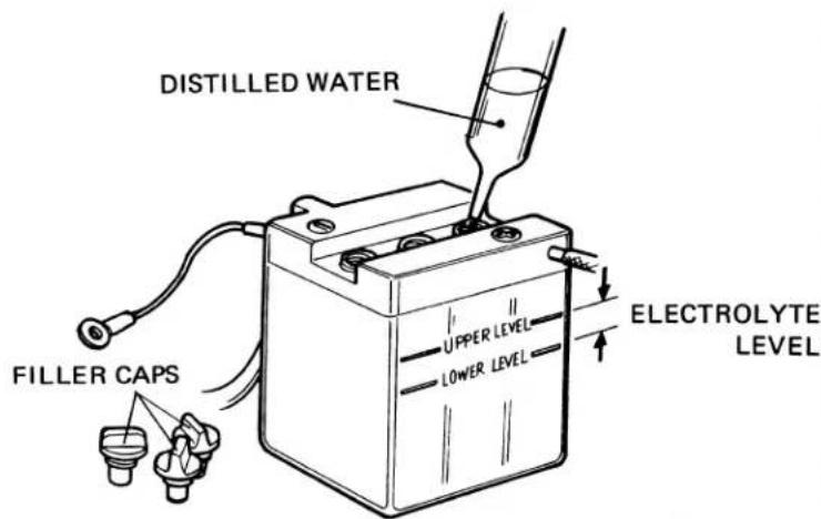
WARNING
The battery electrolyte contains sulfuric acid. Protect your eyes, skin and clothing. In case of contact, flush thoroughly with water and call a doctor if your eyes were exposed.
- Route the battery breather tube as shown in the diagram.
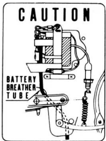
17. BRAKE SHOE WEAR
Replace the brake shoes if the arrow on the brake arm aligns with the reference mark "▲" on the backing plate during full application.
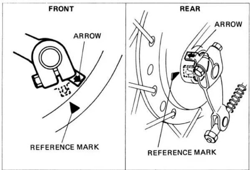
18. BRAKE SYSTEM
• FRONT BRAKE FREE PLAY
- Measure the brake lever free play at lever end.
FREE PLAY : 20–30mm (3/4–1-1/4 in)
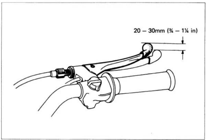
- Make major adjustments with the adjuster located at the front wheel hub. Loosen the lock nut and turn the adjusting nut.
NOTE
Turn in the upper adjuster on the brake lever before adjusting at the wheel hub. Tighten the lock nut.
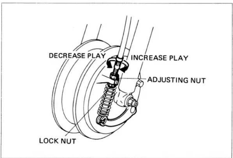
- Minor adjustment can be made with the upper adjuster located on the brake lever. Loosen the lock nut and turn the adjuster. Tighten the lock nut.
- Recheck the brake operation.
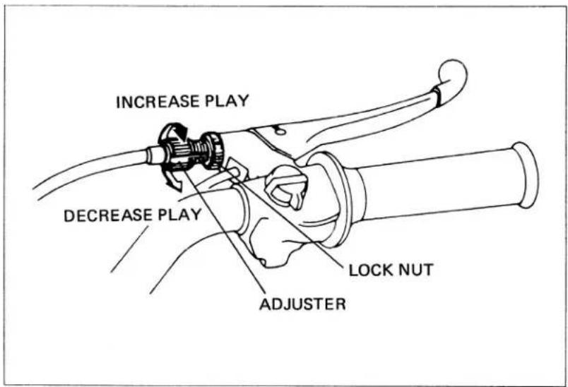
- REAR BRAKE FREE PLAY
- Check the brake pedal free play. FREE PLAY : 20–30mm (3/4–1-1/4 in)
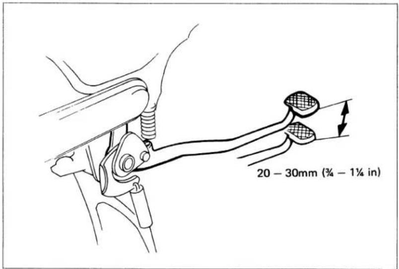
- If adjustment is necessary, turn the rear brake adjusting nut.
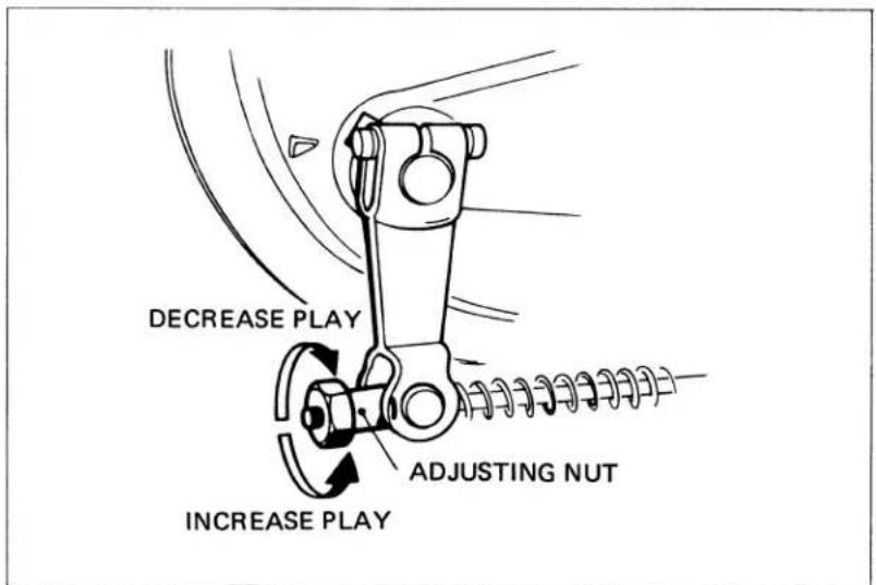
- BRAKE LINKAGE INSPECTION
Check the brake rod and brake lever for loose connections, excessive play, bending or damage. Replace or repair if necessary. Inspect the brake and stopper arms for loose connections or damage. Check that the cotter pin is installed properly.

19. BRAKELIGHT SWITCH
Adjust the brakelight switch so that the brakelight will come on when the brake pedal is depressed 20 mm (3/4 in) where the brake begins engagement. Adjust by turning the switch adjusting nut.
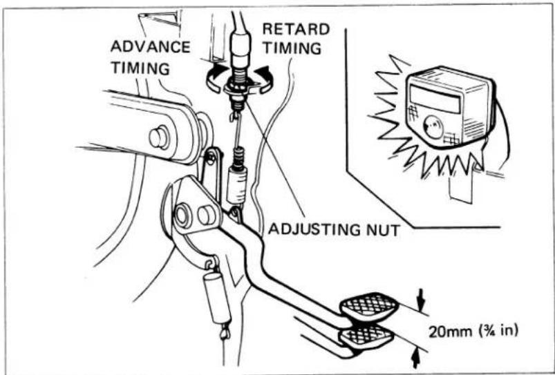
20. HEADLIGHT AIM
Headlight beam can be adjusted vertically and horizontally.
- Adjust vertically by loosening the head-light mounting bolts.
- Adjust the horizontal beam with the beam adjusting screw shown.
NOTE
Adjust the headlight beam as specified by local laws and regulations.
WARNING
An improperly adjusted headlight may blind oncoming drivers, or it may fail to light the road for a safe distance.
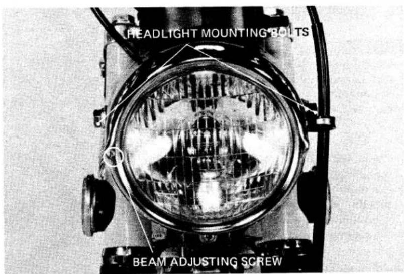
21. CLUTCH FREE PLAY
• INSPECTION
- Check that the engine starts easily without the clutch slipping.
- Check that clutch operation is smooth and light when changing gears, especially when down shifting to neutral.
- ADJUSTMENT
- Loosen the adjusting screw lock nut.
- Turn the adjusting screw clockwise one turn.
- Slowly turn the adjusting screw counterclockwise until a resistance is felt.
- Then turn the adjusting screw clockwise 1/8-1/4 turn, and tighten the lock nut.
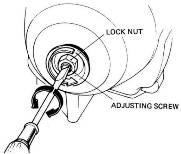
22. SIDE STAND
- Check the rubber pad for deterioration or wear.
- Replace if any wear extends to wear line as shown.
- Check the side stand spring for damage or loss of tension, and the side stand assembly for freedom of movement and bend.
NOTE
When replacing, use a rubber pad with the mark "BELOW 259 lbs ONLY". Spring tension is correct if the measurements fall with 2–3 kg (4.4–6.6 lbs.) when pulling the side stand lower end using a spring scale.
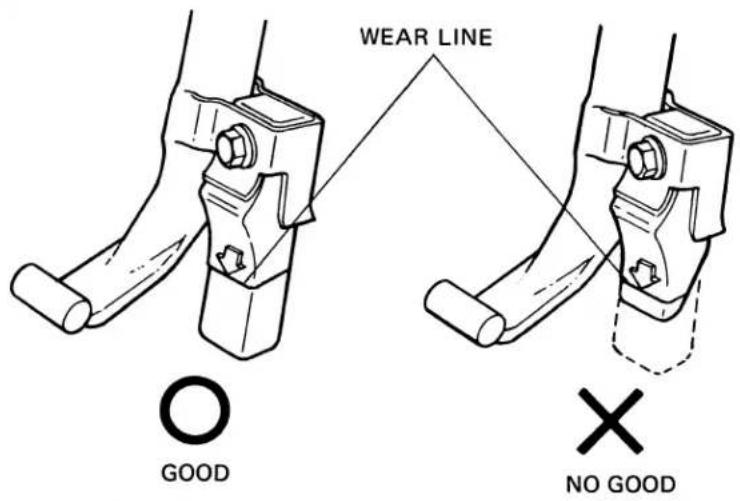
23. SUSPENSION
WARNING
Do not ride a vehicle with faulty suspension. Loose, worn or damaged suspension components may impair vehicle stability, safety and rider control.
- FRONT
- Check the action of the front forks by compressing them several times.
- Check the entire fork assembly for signs of leaks, or damage. Replace any components which are unrepairable.
- Torque all bolts and nuts.
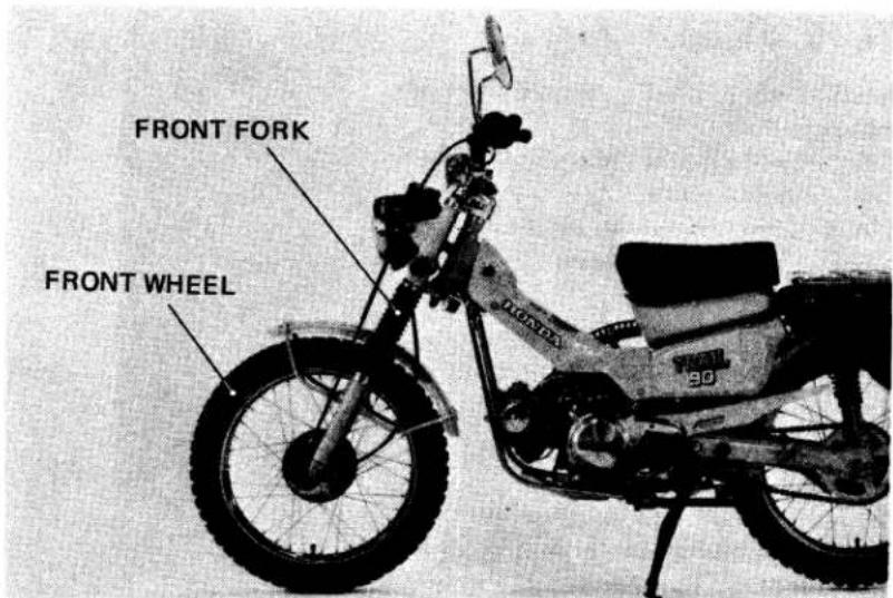
- REAR
- Place the vehicle on its center stand.
- Move the rear wheel sideways with force to see if the swing arm bushings are worn. Replace if excessively worn.
- Check the entire suspension assembly to see if it is securely mounted, damaged or distorted.
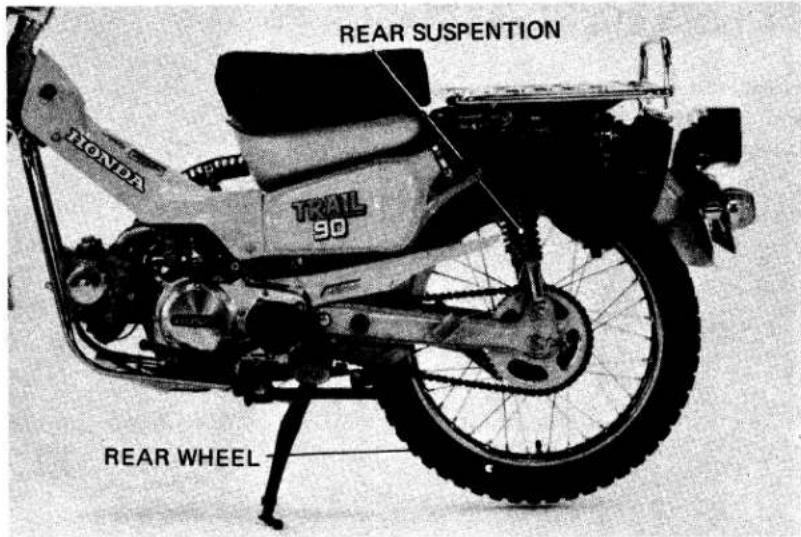
24. SPARK ARRESTER
Clean the spark arrester periodically.
- Remove the spark arrester mounting bolt.
- Remove the spark arrester.
- Start the engine and remove carbon from the muffler by momentarily revving up the engine.
- Clean the spark arrester with a wire brush.
- Reinstall the spark arrester and mounting bolt.
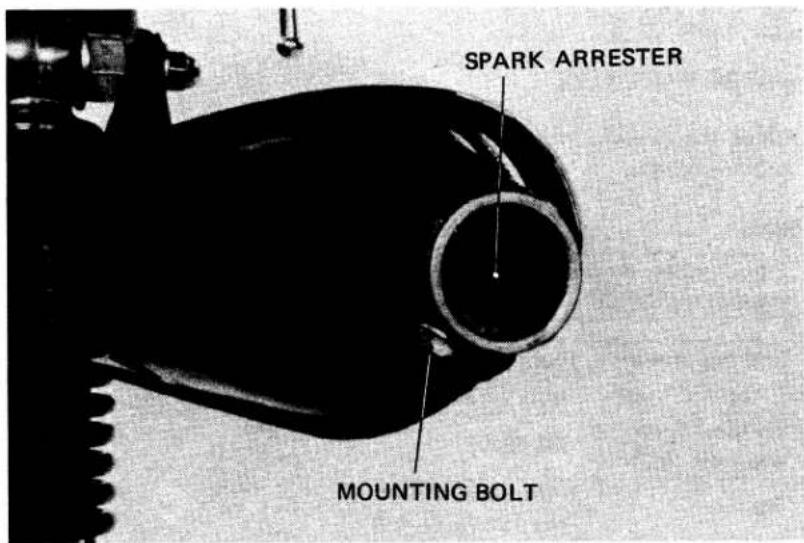
WARNING
- Do not perform this maintenance immediately after the engine has been run because the exhaust system becomes very hot.
- Because of the fire hazard ensure that there are no combustible materials in the area.
- Exhaust gases contain poisonous carbon monoxide. Perform this operation only in a well ventilated area.
- Wear eye protection.
25. NUTS, BOLTS, FASTENERS
Check that all chassis nuts, bolts and fasteners are tightened to their correct torque values. (Refer to page 7)
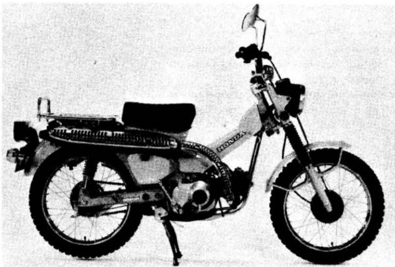
natural_image
Black-and-white photo of a Honda motorcycle with visible engine and front wheel (no text or symbols)26. WHEELS
- TIRE PRESSURE
Check the tires for cuts, imbedded nails, or other objects.
NOTE
| Tire pressure should be checked when the tires are COLD. |
| Cold tire pressure kg/cm2 (psi) | Front; 1.75 (24) |
| Rear; 2.25 (32) | |
| Vehicle capacity load limit kg(lbs) | 100 (220) |
| Tire size | Front; 2.75-17-4PR |
| Rear; 2.75-17-4PR |
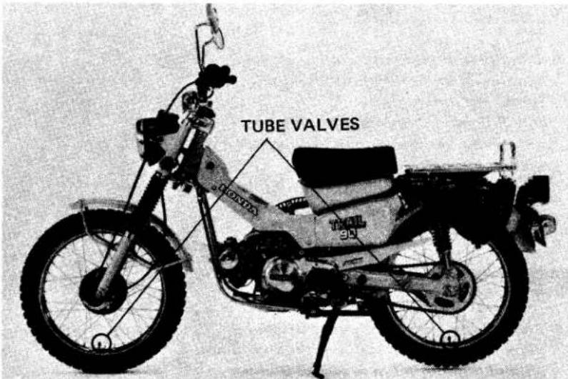
WARNING
Replace tires when tread depth becomes less than 3 mm (1/8 in).
• WHEEL SPOKE RETIGHTENING
- Retighten the wheel spokes periodically.
TORQUE: 0.15–0.30 kg-m
(1.1-2.2 ft-lbs)
- Check front and rear wheel trueness.
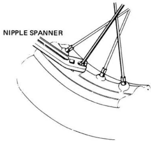
27. STEERING HEAD BEARING
NOTE
Check that the control cables do not interfere with the rotation of the handlebars.
Raise the front wheel off the ground. Check that the handlebar rotates freely.
If the handlebar moves unevenly, binds or has vertical movement, adjust the steering head bearing by turning the steering head adjusting nut with a pin spanner.
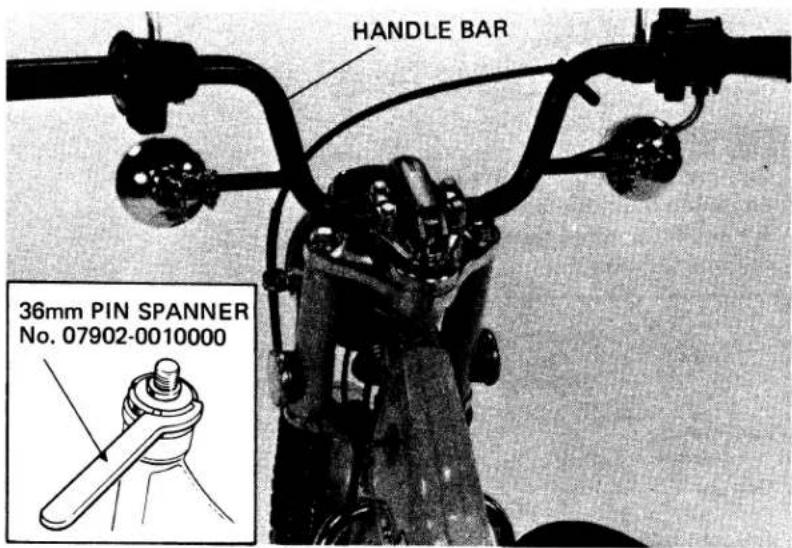
1. CARBURETOR
SPECIFICATIONS
WARNING
| Gasoline is extremely flammable and is explosive under certain conditions. Do not smoke or allow flames or sparks in your working area. |
| Item | Standard spec.(2,000m.6,500ftmax.) | High altitude spec.(1,500m.5,000ftmin.) |
| Identification number | PB28A | ← |
| Main jet | #65 | #60(optional) |
| Jet needle mark | 18A | ← |
| Float height | 10.7mm (0.43 in) | ← |
| Idle speed | 1,300±100rpm | ← |
| Pilot screw | See page 24 |
2. DISASSEMBLY
AND ASSEMBLY
Refer to the base CT90 Shop Manual for disassembly and assembly procedures.
NOTE
When disassembling fuel system parts, not the O-ring locations. Replace them with new ones during reassembly. The float bowl has a drain plug that can be loosened to drain residual gasoline.
3. PILOT SCREW
INITIAL SETTING
NOTE
The pilot screw is factory pre-set. Do not adjust unless the carburetor is overhauled or a high altitude main jet installed.
Turn the pilot screw clockwise until it seats lightly and back it out 1-1/4 turns. This is a preliminary setting prior to the final Pilot Screw Adjustment.
CAUTION
Damage to the pilot screw seat will occur if the pilot screw is tightened against the seat.
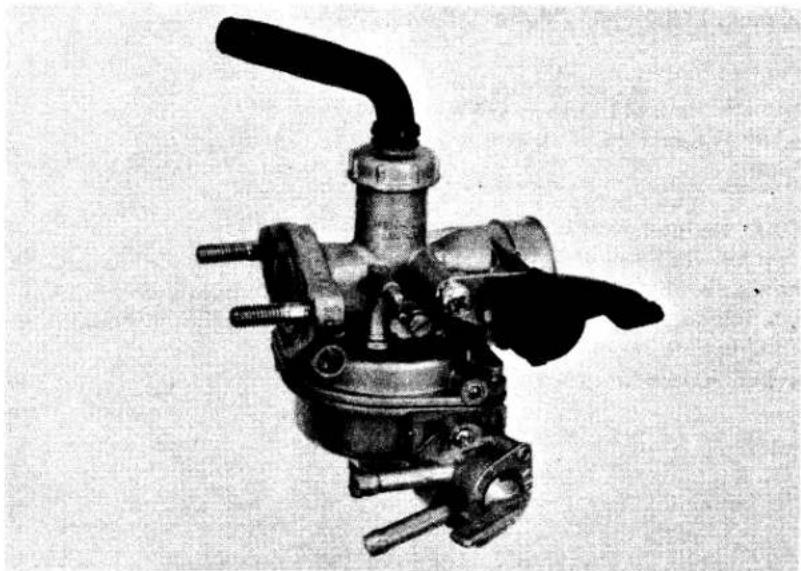
natural_image
Mechanical component with lever and multiple ports (no visible text or symbols)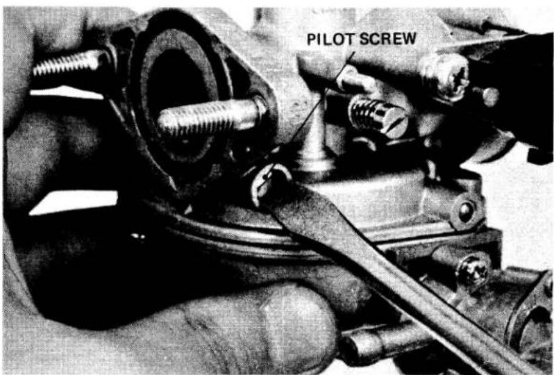
4.PILOT SCREW
ADJUSTMENT
- Warm up the engine to operating temperature. Stop and go driving for ten minutes is sufficient.
- Attach a tachometer.
- Adjust the idle speed with the throttle stop screw.
IDLE SPEED : 1,300 ± 100 rpm
- Screw the pilot screw in gradually until the engine stops.
- Turn the pilot screw 1 turn out from this position.
- Restart the engine and readjust the idle speed stop screw, if necessary.
5. HIGH ALTITUDE
ADJUSTMENT
The carburetor must be adjusted for high altitude riding (above 2000m 6500ft).
STANDARD SETTING : 2000m (6500ft)
max.
HIGH ALTITUDE SETTING : 1500m
(5000ft) min.
High altitude carburetor adjustment is done as follows:
- Remove and disassemble the carburetor.
- Replace the main jet with the high altitude type. (See page 24.)
- Assemble and install the carburetor.
- Screw the pilot screw in 3/8 of a turn.
- Start the engine and adjust the idle speed with the throttle stop screw.
NOTE
* Adjust the idle speed at high altitude to ensure proper high altitude operation.
* Readjust the pilot screw if the engine idles rough, misses, or stalls, according to the instructions on pages 24 and 25.
CAUTION
Sustained operation at altitudes lower than 1,500m (5,000 ft) with the high altitude specifications may cause engine overheating and damage.
Reinstall the standard main jet and turn the pilot screw 3/8 turn out when operating the vehicle below 1,500 m (5,000 ft).
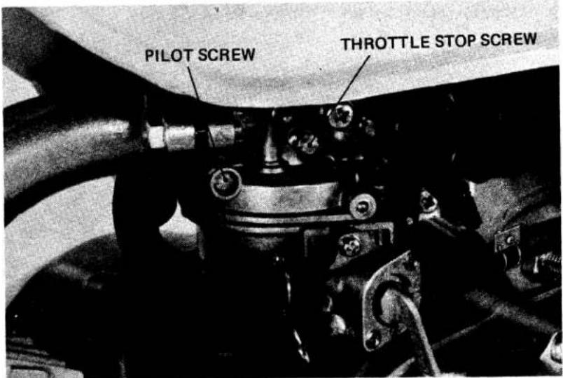
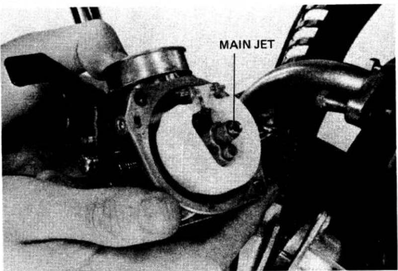
Check the pipe routing and secure the drain plug.
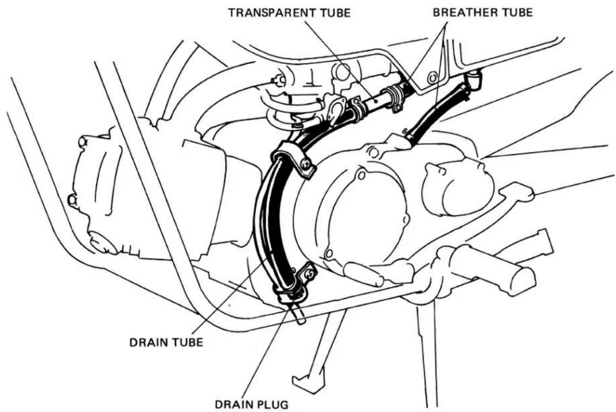
1. Engine cranks but won't start
* No spark at plug — Ref. 2
* Ignition malfunction
* No fuel in tank
* No fuel to carburetor
* Engine flooded with fuel
* Air cleaner clogged
* Intake air leak
* Improper choke operation
* Improper throttle operation
* Low oil level — Ref. 6
* No or low oil pressure — Ref. 8, 10
2. Hard starting or stalling after starting
* Worn spark plug and /or breaker points
* Ignition timing incorrect — Ref. 1
'* Ignition malfunction
* Idle speed incorrect
* Incorrect idle air/fuel mixture — Ref. 4, 5
* Carburetor malfunction
* Fuel contaminated
* Improper choke operation
* Low compression – Ref. 3
* Clogged muffler
* Oil level low — Ref. 6
* No or low oil pressure — Ref. 8, 10
3. Rough idle
* Worn spark plug and/or breaker points
* Ignition timing incorrect — Ref. 1
* Ignition malfunction
* Idle speed incorrect
* Incorrect carburetor air/fuel mixture — Ref. 4, 5
* Carburetor malfunction
* Fuel contaminated
* Low compression — Ref. 3
4. Misfiring during acceleration
* Worn spark plug, breaker points and/or ignition wires
* Incorrect ignition timing — Ref. 1
* Ignition malfunction
* Incorrect carburetor air/fuel mixture — Ref. 4, 5
5. Backfiring
* Ignition timing incorrect — Ref. 1
* Ignition malfunction
* Incorrect carburetor air/fuel mixture — Ref. 4, 5
* Carburetor malfunction
6. Poor performance (Driveability) and poor fuel economy
* Ignition timing incorrect — Ref. 1
* Ignition malfunction
* Incorrect carburetor air/fuel mixture — Ref. 4, 5
* Fuel system clogged
* Low compression — Ref. 3
* Oil level too low — Ref. 6
* Oil contamination – Ref. 7
* Low oil pressure — Ref. 8
* High oil pressure — Ref. 9
Ref. 1: Ignition timing incorrect
* Incorrect breaker point gap
* Faulty spark advancer
Ref. 2: No spark at plug
* Poorly connected, broken or shorted wires
* Faulty ignition switch
* Faulty ignition coil
* Faulty high tension cord
* Faulty AC generator
* Battery charge low
* Burned or pitted contact breaker points
* Faulty spark plug
* Ignition timing incorrect
Ref. 3: Low compression
* Incorrect valve adjustment
* Burned or bent valves
* Incorrect valve timing
* Weak valve spring
* Leaking or damaged head gasket
* Warped or cracked cylinder head
* Improper valve seating
* Worn piston rings and/or cylinder
Ref. 4: Lean mixture
* Clogged fuel jets
* Faulty float valve
* Float level low
* Fuel cap vent blocked
* Fuel strainer screen clogged
* Restricted fuel line
* Intake air leak
* Pilot screw misadjusted
Ref. 5: Rich mixture
* Clogged air jets
* Faulty float valve
* Float valve too high
* Choke stuck closed
* Pilot screw misadjusted
* Clogged air cleaner
Ref. 6: Oil level low
* External oil leaks
* Worn piston rings
* Worn valve guide and/or stem seal
Ref. 7: Oil contamination
* Engine oil not changed regularly
* Worn piston rings
*Oil filter rot cleaned regularly.
Ref. 8: Low oil pressure; Oil pressure lamp lights on.
* Plugged oil filter screen
* Worn oil pump
* Oil level low
Ref. 9: High oil pressure; Broken oil ring or gasket
* Incorrect oil being used
Ref. 10: No oil pressure
* No oil in crankcase
* Faulty oil pump
* Leaks from oil circuit
INTRODUCTION
This HONDA CT90 1979 Shop Manual Addendum contains information pertinent to the 1979 CT90. Refer to the base shop manual for procedures and service data not included in this addendum.
CONTENTS
MAINTENANCE SCHEDULE 138
INSPECTION AND ADJUSTMENT ....139
ALL INFORMATION, ILLUSTRATIONS, DIRECTIONS AND SPECIFICATIONS INCLUDED IN THIS PUBLICATION ARE BASED ON THE LATEST PRODUCT INFORMATION AVAILABLE AT THE TIME OF APPROVAL FOR PRINTING. HONDA MOTOR CO., LTD. RESERVES THE RIGHT TO MAKE CHANGES AT ANY TIME WITHOUT NOTICE AND WITHOUT INCURRING ANY OBLIGATION WHATEVER.
NO PART OF THIS PUBLICATION MAY BE REPRODUCED WITHOUT WRITTEN PERMISSION.
HONDA MOTOR CO., LTD. Service Publications Office
I. MAINTENANCE SCHEDULE
Perform the PRE-RIDE INSPECTION in the Owner's Manual at each maintenance period.
I: Inspect, Clean, Adjust, Lubricate or Replace if necessary.
C: Clean
R: Replace
A: Adjust
L: Lubricate
| ITEM\FREQUENCY | WHICHEVER OCCURSFIRST →↓ | ODOMETER READINGNOTE (3) | Refer to 781⁄2EmissionsAddendum | ||||
| 600mi.(1000km) | 2500mi(4000 km) | 5000mi.(8000 km) | 7.500mi.(12000 km) | ||||
| EVERY | |||||||
| EMISSION RELATED ITEMS | ENGINE OIL | YEAR | R | REPLACE EVERY1250mi (2000 km) | Page 7 | ||
| • ENGINE OIL FILTER SCREEN | C | Page 8 | |||||
| CRANKCASE BREATHER | NOTE (1) | C | C | C | Page 9 | ||
| AIR CLEANER | NOTE (2) | C | C | C | Page 9 | ||
| • FUEL LINES | I | I | I | Page 10 | |||
| SPARK PLUG | I | I | R | Page 10 | |||
| • VALVE CLEARANCE | I | I | I | I | Page 11 | ||
| • CONTACT BREAKER POINTS | I | I | I | I | Page 11 | ||
| • IGNITION TIMING | I | I | I | I | Page 12 | ||
| • CAM CHAIN TENSION | A | A | A | A | Page 13 | ||
| • THROTTLE OPERATION | I | I | I | I | Page 14 | ||
| • CARBURETOR IDLE SPEED | I | I | I | I | Page 14 | ||
| • CARBURETOR CHOKE | I | I | I | Page 14 | |||
| NON-EMISSION RELATED ITEMS | DRIVE CHAIN | NOTE (4) | I, L EVERY 300 mi (500 km) | Page 15 | |||
| BATTERY | MONTH | I | I | I | I | Page 16 | |
| BRAKE SHOE WEAR | I | I | I | Page 17 | |||
| BRAKE SYSTEM | I | I | I | I | Page 17 | ||
| • BRAKE LIGHT SWITCH | I | I | I | I | Page 19 | ||
| • HEADLIGHT AIM | I | I | I | I | Page 19 | ||
| CLUTCH FREE PLAY | I | I | I | I | Page 20 | ||
| SIDE STAND | I | I | I | Page 20 | |||
| • SUSPENSION | I | I | I | I | Page 20 | ||
| • SPARK ARRESTER | C | C | C | Page 21 | |||
| • NUTS, BOLTS, FASTENERS | NOTE (4) | I | I | I | I | Page 22 | |
| •• WHEELS/SPOKES | NOTE (4) | I | I | I | I | Page 22 | |
| •• STEERING HEAD BEARING | I | I | Page 23 | ||||
* Should be serviced by an authorized HONDA dealer, unless the owner has proper tools and service data and is mechanically qualified.
** In the interest of safety, we recommend these items be serviced ONLY by an authorized HONDA dealer.
NOTES: (1) Service more frequently when riding in rain or at full throttle (U.S.A. only)
(2) Service more frequently if riding in dusty areas.
(3) For higher odometer readings, repeat at the frequency interval established here.
(4) Service more frequently when riding OFF-ROAD.
II. INSPECTION AND ADJUSTMENT
1. ENGINE OIL
• ENGINE OIL LEVEL CHECK
- Place the vehicle on its center stand, and remove the oil filler cap/dipstick and wipe it clean.
- Reinsert the dipstick and check the oil level.
NOTE
Do not screw the dipstick in when making this check.
- If the oil level is below the lower level mark, fill to the upper level mark with the recommended oil.
• ENGINE OIL CHANGE
- Remove oil filler cap and drain plug after the engine is warm, and drain the oil.
- Install the drain plug, and make sure that the sealing washer is in good condition.
TORQUE: 2.0–3.5 kg-m (15–25ft-lbs)
- Fill crankcase with the recommended oil.
OIL CAPACITY: 0.9 lit. (0.95 US.qt.) approx.
RECOMMENDED OIL:
Use HONDA 4-STROKE OIL or equivalent.
API SERVICE CLASSIFICATION: SE VISCOSITY:
General, all temperatures; SAE 10W–40 Alternates:
| Above 15°C/60°F | SAE 30 |
| -10°C/15°F-15°C/60°F | SAE 20 or SAE 20W |
| Above -10°C (15°F) | SAE 20W-50 |
| Below 0°C/32°F | SAE 10W |
- Reinstall the oil filler cap.
- Start the engine and allow it to idle for 2-3 minutes.
- Stop the engine and make sure that the oil level is at the upper level mark with the vehicle in an upright position, and that there are no oil leaks.
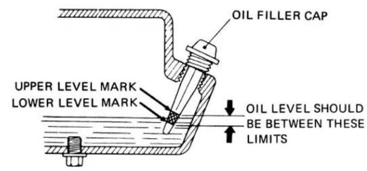
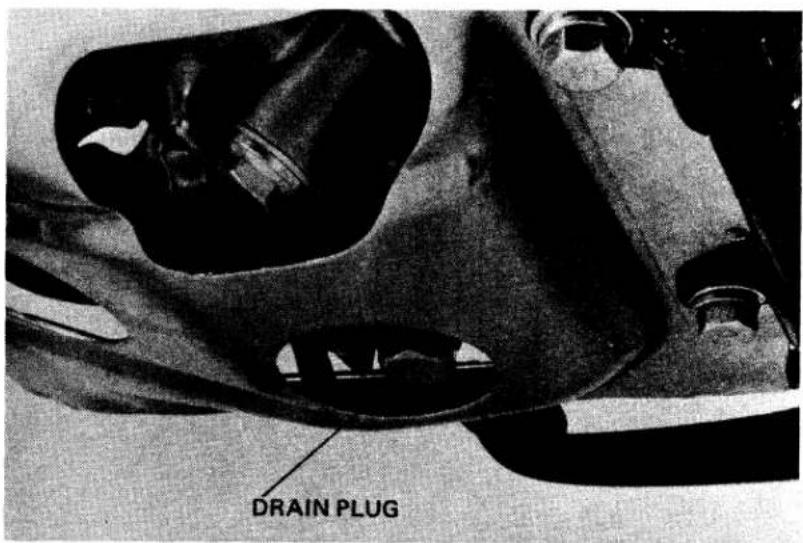
OIL SPECIFICATION
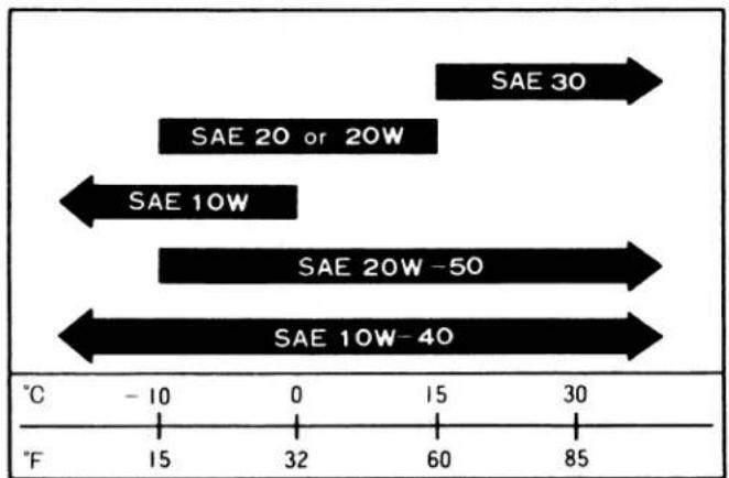
MEMO
INTRODUCTION
This 1980 Shop Manual Addendum contains information for the 1980 CT110. Refer to the base shop manual for procedures and service data not included in this addendum.
ALL INFORMATION, ILLUSTRATIONS, DIRECTIONS AND SPECIFICATIONS INCLUDED IN THIS PUBLICATION ARE BASED ON THE LATEST PRODUCT INFORMATION AVAILABLE AT THE TIME OF APPROVAL FOR PRINTING. HONDA MOTOR CO., LTD. RESERVES THE RIGHT TO MAKE CHANGES AT ANY TIME WITHOUT NOTICE AND WITHOUT INCURRING ANY OBLIGATION WHATEVER.
NO PART OF THIS PUBLICATION MAY BE REPRODUCED WITHOUT WRITTEN PERMISSION.
HONDA MOTOR CO., LTD.
Service Publications Office
CONTENTS
I. SPECIFICATIONS ..... 142
II. SERVICE INFORMATION.....144
III. INSPECTION/ADJUSTMENT....151
IV. ENGINE....155
V. CARBURETOR 161
VI. REAR WHEEL/TAIL LIGHT....164
VII. ELECTRICAL 166
VIII. WIRING DIAGRAM 170
I. SPECIFICATIONS
| Items | Specifications |
| DIMENSION | |
| Overall Length | 1,870 mm (73.6 in) |
| Overall Width | 750 mm (29.5 in) |
| Overall Height | 1,060 mm (41.7 in) |
| Wheel Base | 1,220 mm (48.0 in) |
| Seat Height | 775 mm (30.5 in) |
| Ground Clearance | 180 mm (7.1 in) |
| Dry Weight | 89 kg (196 lb) |
| FRAME | |
| Type | Back bone |
| Front Suspension, Travel | Telescopic fork, 102 mm (4.0 in) |
| Rear Suspension, Travel | Swing arm, 77 mm (3.0 in) |
| Front Tire Size, Type | 2.75-17-4 PR Knobby, tire air pressure 1.75 kg/cm^2 (24 psi) |
| Rear Tire Size, Type | 2.75-17-4 PR Knobby, tire air pressure 2.25 kg/cm^2 (32 psi) |
| Front Brake | Internal expanding shoes |
| Rear Brake | Internal expanding shoes |
| Fuel Capacity | 5.5 lit. (1.5 U.S. gal, 1.2 Imp. gal) |
| Fuel Reserve Capacity | 0.8 lit. (0.2 U.S. gal, 0.18 Imp. gal) |
| Auxiliary Fuel Tank Capacity | 2.3 lit. (0.6 U.S. gal, 0.54 Imp. gal) |
| Caster Angle | 63^ |
| Trail Length | 82 mm (3.2 in) |
| Front Fork Oil Capacity | To fill dry fork assembly130 - 140 cc (4.4 - 4.7 ozs)To refill after draining120 - 130 cc (4.1 - 4.4 ozs) |
| ENGINE | |
| Type | Air cooled 4-stroke O.H.C. engine |
| Cylinder Arrangement | Single cylinder 75 inclined from vertical52 x 49.5 mm (2.047 x 1.948 in) |
| Bore and Stroke | |
| Displacement | 105.1 cc (6.39 cu in) |
| Compression Ratio | 8.5 : 1 |
| Carburetor, Venturi Dia. | Piston valve type, venturi dia. 18 mm (0.71 in) |
| Valve train | Chain driven over head camshaft |
| Oil Capacity | 1.1 lit. (1.2 U.S. qt. 1.0 Imp. qt) |
| Lubrication System | Forced pressure and wet sump |
| Fuel Required | All gasoline 91 RON min. |
| Air Filtration | Oiled polyurethane foam filter |
| Intake Valve: OpensClosesExhaust Valve: OpensClosesValve ClearanceEngine Dry WeightPilot Screw SettingIdle Speed | 5° BTDC20° ABDC25° BBDC5° ATDCIN/EX. 0.05 mm (0.002 in)23 kg (51 lb)See page 1621,300 rpm |
| DRIVE TRAINClutchTransmissionPrimary ReductionGear Ratio IIIIIIIVFinal ReductionGear Shift PatternDrive Chain | Wet multi-plate automatic4-speed constant mesh3.7222.5381.6111.1900.9583.000, drive sprocket 15 T, driven sprocket 45 TLeft foot operated return system 1-N-2-3-4D.I.D. 428D, RK428M; 104 links |
| ELECTRICALIgnitionIgnition Advance :“ F ” markMax. advanceStarting SystemAlternatorBattery CapacityFuse CapacitySpark Plug[ ] Canada ModelCondenser Capacity | A.C. generator and ignition coil10° BTDC22 ± 2° at 3,400 rpmKick starterA.C. Generator, 66w/5,000 rpm6V - 4 AH10 amp.For cold climate ND X22ES-U [X22 ESR-U](below 5°C/41°F) NGK D7EA [DR7ES]Standard ND X24ES-U [X24ESR-U]NGK D8EA [DR8ES-L]For extended high ND X27ES-U [X27ESR-U]speed riding NGK D9EA [DR8ES]0.25μF ± 10% |
II. SERVICE INFORMATION
1. SERVICE DATA
ENGINE
Unit: mm (in.)
| Item | Standard | Service Limit | ||||
| Cylinder | I.D. | 52.020-52.030 (2.0480-2.0483) | 52.10 (2.051) | |||
| Taper | 0-0.010 (0-0.0004) | 0.05 (0.002) | ||||
| Out-of-round | 0-0.010 (0-0.0004) | 0.05 (0.002) | ||||
| Piston O. D. | 51.970-51.990 (2.0461-2.0468) | 51.80 (2.039) | ||||
| Piston pin I. D. | 15.002-15.008 (0.5906-0.5909) | 15.04 (0.5921) | ||||
| Piston pin O. D. | 14.994-15.000 (0.5903-0.5906) | 14.96 (0.589) | ||||
| Piston ring end gap | Top | 0.15-0.35 (0.006-0.014) | 0.50 (0.020) | |||
| Second | 0.15-0.35 (0.006-0.014) | 0.50 (0.020) | ||||
| Piston-to-piston ring clearance | Top | 0.010-0.040 (0.0004-0.0016) | 0.12 (0.005) | |||
| Second | 0.015-0.045 (0.0006-0.0018) | 0.12 (0.005) | ||||
| Piston ring thickness | Top | 1.175-1.190 (0.0463-0.0469) | 1.13 (0.044) | |||
| Second | 1.175-1.190 (0.0463-0.0469) | 1.13 (0.044) | ||||
| Valve stem O. D. | IN | 5.450-5.465 (.0.2146-0.2152) | 5.435 (0.2139) | |||
| EX | 5.430-5.445 (0.2138-0.2144) | 5.415 (0.2132) | ||||
| Valve guide I. D. | IN/EX | 5.475-5.485 (0.2157-0.2161) | 5.525 (0.2175) | |||
| Valve-to-valve guide clearance | IN | 0.010-0.035 (0.0004-0.0014) | 0.08 (0.003) | |||
| EX | 0.030-0.055 (0.0012-0.0022) | 0.10 (0.004) | ||||
| Valve spring | Free length | Outer | 35.0 (1.38) | 33.7 (1.32) | ||
| Inner | 31.1 (1.22) | 29.9 (1.18) | ||||
| Preload/length | Outer kg/mm (lbs./in.) | 7.2-8.8/29.6 (15.88-19.40/1.17) | — | |||
| Inner kg/mm (lbs./in.) | 3.5-4.3/25.5 (7.72-9.48/1.00) | — | ||||
| Valve face width | IN/EX | 1.2-1.5 (0.05-0.06) | 1.8 (0.07) | |||
| Valve seat width | IN/EX | 1.0 (0.04) | 1.6 (0.06) | |||
| Cam height | IN/EX | 24.118-24.278 (0.9495-0.9756) | 23.8 (0.94) | |||
| Camshaft O. D. | R. End | 17.934-17.945 (0.7060-0.7065) | 17.90 (0.705) | |||
| L. End | 25.932-25.945 (1.0210-1.0215) | 25.90 (1.020) | ||||
| Camshaft end bearing I. D. | R. End | 18.000-18.018 (0.7087-0.7094) | 18.05 (0.711) | |||
| L. End | 26.000-26.020 (1.0236-1.0244) | 26.05 (1.026) | ||||
| Clutch disc thickness | 2.8-2.9 (0.1102-0.1142) | 2.4 (0.10) | ||||
| Clutch plate thickness | 1.93-2.07 (0.076-0.082) | 1.85 (0.073) | ||||
| Clutch plate warpage | 0.2 (0.01) | 0.5 (0.02) | ||||
| Clutch spring | Free length | 27.0 (1.06) | 26.0 (1.02) | |||
| Preload/length kg/mm (lbs/in) | 10.4/15 (22.9/0.6) | — | ||||
| Crankshaft run out (at ends) | 0-0.025 (0-0.0010) | 0.10 (0.004) | ||||
| Crankshaft bearing play | Axial | 0.10-0.35 (0.004-0.019) | 0.8 (0.03) | |||
| Radial | 0.-0.01 (0.-0.0004) | 0.05 (0.002) | ||||
| Connecting rod small end I. D. | 15.016-15.034 (0.5912-0.5919) | 15.05 (0.593) | ||||
| Connecting rod big end side clearance | 0.10-0.35 (0.004-0.019) | 0.8 (0.03) | ||||
| Connecting rod big end radial clearance | 0-0.01 (0-0.0004) | 0.05 (0.002) | ||||
| Clutch drive gear I.D. | 24.00-24.02 (0.945-0.496) | 24.15 (0.951) | ||||
| Clutch center guide O.D. | 22.00-22.10 (0.866-0.870) | 21.85 (0.860) | ||||
| Clutch center guide-to-crankshaft clearance | 0.005-0.047 (0.0002-0.0019) | 0.15 (0.006) | ||||
mm (in)
| Item | Standard | Service Limit | |||
| Rocker arm shaft O. D. | 9.972–9.987 | (0.3926–0.3932) | 9.92 | (0.391) | |
| Rocker arm I. D. | 10.000–10.015 | (0.3937–0.3943) | 10.10 | (0.398) | |
| Crankshaft-to-clutch center guide clearance | 0.005–0.047 | (0.0002–0.0019) | 0.15 | (0.060) | |
| Tensioner spring free length | Spring A | 65 | (2.6) | 60 | (2.4) |
| Spring B | 49.8 | (19.92) | 40 | (1.6) | |
| Oil pump | Inner-to-outer rotor clearance | 0.15 | (0.006) | 0.2 | (0.01) |
| Outer rotor-to-body clearance | 0.15–0.20 | (0.006–0.008) | 0.25 | (0.010) | |
| Rotor-to-cover clearance | 0.02–0.07 | (0.001–0.003) | 0.12 | (0.005) | |
| Shift fork I. D. | 42.00 | (1.654) | 42.1 | (1.66) | |
| Shift fork ends thickness | 5.96–6.04 | (0.235–0.238) | 5.70 | (0.224) | |
| Shift drum O. D. | 41.950–41.975 | (1.6516–1.6526) | 41.80 | (1.646) | |
| Shift drum groove width | 6.1–6.2 | (0.240–0.244) | 6.4 | (0.25) | |
| Shift fork-to-shift drum clearance | 0.05 | (0.002) | 0.2 | (0.01) | |
FRAME
| Item | Standard | Service Limit | |||
| Front/rear axle shaft runout | 0-0.05 | (0-0.002) | 0.2 | (0.01) | |
| Front/rear wheel bearing play | Axial | 0-0.05 | (0-0.002) | 0.1 | (0.004) |
| Radial | 0.003-0.008 | (0.0001-0.0003) | 0.04 | (0.002) | |
| Front/rear brake drum I. D. | 110.0 | (4.33) | 111.0 | (4.37) | |
| Wheel rim | Face runout | 0-0.5 | (0-0.02) | 1.0 | (0.04) |
| Eccentricity | 0-0.5 | (0-0.02) | 1.0 | (0.04) | |
| Front fork spring | Free length | 203 | (8.0) | 185 | (7.3) |
| Rear shock absorber spring | Free length | 223 | (8.8) | 207 | (8.2) |
| Front fork piston O. D. | 30.95-30.97 | (1.219-1.220) | 30.85 | (1.215) | |
| Front fork slider I.D. | 31.00-31.04 | (1.221-1.223) | 31.10 | (1.225) | |
| Brake lining thickness | 4.0 | (0.16) | 2.0 | (0.08) | |
2. TORQUE SPECIFICATIONS
ENGINE
| Tightening point | Q'ty | Thread dia. | Torque kg-m (lbs-ft) |
| Cylinder head nut | 4 | 8 | 1.8 – 2.1 (13.0 – 15.2) |
| Camshaft sprocket bolt | 2 | 6 | 0.9 – 1.2 (6.5 – 8.7) |
| Cam chain guide roller bolt | 1 | 6 | 0.9 – 1.4 (6.5 – 10.1) |
| Spark advancer bolt | 1 | 6 | 0.8 – 1.2 (5.8 – 8.7) |
| Clutch lock nut | 1 | 16 | 4.0 – 5.0 (29.0 – 36.2) |
| A. C. generator rotor nut | 1 | 14 | 6.0 – 7.0 (43.4 – 50.7) |
| Shift drum bolt | 1 | 6 | 0.8 – 1.2 (5.8 – 8.7) |
FRAME
| Tightening point | Q'ty | Thread dia. | Torque kg-m (lbs-ft) |
| Handlebar setting bolts | 4 | 6 | 0.8 – 1.2 (5.8 – 8.7) |
| Steering stem nut | 1 | 22 | 6.0 – 7.0 (43.4 – 50.7) |
| Front fork bolt | 2 | 10 | 3.5 – 4.5 (25.3 – 32.6) |
| Steering stem bolt | 2 | 8 | 1.8 – 2.5 (13.0 – 18.1) |
| Swingarm pivot bolt | 1 | 10 | 4.0 – 6.0 (29.0 – 43.4) |
| Rear shock absorber upper nut | 2 | 10 | 2.5 – 3.5 (18.1 – 25.3) |
| Rear shock absorber lower nut | 2 | 8 | 2.5 – 3.5 (18.1 – 25.3) |
| Front axle nut | 1 | 10 | 3.5 – 5.0 (25.3 – 36.2) |
| Rear axle nut | 1 | 10 | 4.0 – 5.0 (28.9 – 36.2) |
| Rear brake stop arm bolt | 2 | 8 | 1.8 – 2.5 (13.0 – 18.1) |
| Engine hanger bolt | 2 | 10 | 3.0 – 4.0 (21.7 – 29.0) |
| Foot peg bolt | 4 | 8 | 1.8 – 2.5 (13.0 – 18.1) |
Torque specifications listed above are important tightening points. Others should be tightened to standard torque specifications below.
Standard Torque Specifications
| Type | Torque kg-m (lbs-ft) | Type | Torque kg-m (lbs-ft) | ||
| 5 mm bolt and nut | 0.45 – 0.60 | (3.3 – 4.3) | 5 mm screw | 0.35 – 0.50 | (2.5 – 3.6) |
| 6 mm bolt and nut | 0.8 – 1.2 | (5.8 – 8.7) | 6 mm screw | 0.7 – 1.1 | (5.1 – 8.0) |
| 8 mm bolt and nut | 1.8 – 2.5 | (13.0 – 18.1) | 6 mm flange bolt and nut | 1.0 – 1.4 | (7.2 – 10.1) |
| 10 mm bolt and nut | 3.0 —4.0 | (21.7 – 29.0) | 8 mm flange bolt and nut | 2.4 – 3.0 | (17.4 – 21.7) |
| 12 mm bolt and nut | 5.0 —6.0 | (36.2 – 43.4) | 10 mm flange bolt and nut | 3.0 – 4.0 | (21.7 – 29.0) |
3. TOOLS
SPECIAL TOOLS
| TOOL NAME | TOOL NO. |
| Ball race driver | 07944-1150001 |
| Valve guide reamer | 07984-0980000 |
COMMON TOOLS
| TOOL NAME | TOOL NO. | SPECIAL TOOL NO. |
| Float level gauge | 07401-0010000 | —— |
| Pin spanner | 07702-0010000 | 07902-2400000 |
| Tappet adjust wrench 8 x 9 | 07708-0030100 | 07908-0010000 |
| Tappet adjuster B | 07708-0030400 | |
| Lock nut wrench 20 x 24 | 07716-0020100 | 07916-6390001 |
| Lock nut wrench 26 x 30 | 07716-0020200 | 07915-0300000 |
| Extension bar | 07716-0020500 | —— |
| Flywheel puller | 07733-0010000 | 07933-0010000 |
| Bearing driver outer 37 x 40 | 07746-0010200 | 07945-098000007946-3640000 |
| Driver pilot 12 | 07746-0040200 | —— |
| Bearing driver outer 12 x 47 | 07746-0010300 | 07946-300020007945-3330100 |
| Driver pilot 20 | 07746-0040500 | —— |
| Driver handle inner B | 07746-0020100 | 07945-8120200 |
| Driver handle inner C | 07746-0030100 | 07945-3330200 |
| Bearing driver inner 25 | 07746-0030200 | 07945-3710200 |
| Driver handle outer A | 07749-0010000 | 07949-300000007949-6110000 |
| Driver body | 07747-0010100 | 07947-1180001 |
| Driver attachment | 07747-0010300 | |
| Valve spring compressor | 07757-0010000 | 07957-3290001 |
| Shock absorber compressor | 07959-3290001 | —— |
| Nipple spanner | 07701-0020100 | —— |
| Valve guide remover 5.5 | 07742-0010100 | 07942-3290100 |
| Valve guide driver B | 07742-0020200 | 07942-3290200 |
| Valve guide cutter | 07742-0030100 | —— |
| Pilot 5.5 mm | 07742-0030200 | —— |
4. MAINTENANCE SCHEDULE
Perform the PRE-RIDE INSPECTION in the Owner's Manual at each scheduled maintenance period.
I: Inspect and Clean, Adjust, Lubricate or Replace, if necessary.
C: Clean
R: Replace
A: Adjust
L: Lubricate
| FREQUENCYITEM | WHICHEVER→COMESFIRST ↓ | ODOMETER READING (NOTE 4) | |||||
| 600mi.(1,000km) | 2,500mi.(4,000km) | 5,000mi.(8,000km) | 7,500mi.(12,000km) | Refer to | |||
| EVERY | |||||||
| EMISSION RELATED ITEMS | * FUEL LINE | I | I | I | Page 118 | ||
| * THROTTLE OPERATION | I | I | I | I | Page 122 | ||
| * CARBURETOR-CHOKE | I | I | I | Page 122 | |||
| AIR CLEANER | NOTE 1 | C | C | C | Page 117 | ||
| CRANKCASE BREATHER (USA only) | NOTE 2 | C | C | C | Page 117 | ||
| SPARK PLUG | R | R | R | Page 151 | |||
| * VALVE CLEARANCE | I | I | I | I | Page 152 | ||
| * CONTACT BREAKER POINTS | I | I | R | I | Page 152 | ||
| * IGNITION TIMING | I | I | I | I | Page 153 | ||
| ENGINE OIL | YEAR | R | REPLACE EVERY1,250mi. (2,000km) | Pages 151 | |||
| * ENGINE OIL FILTER SCREEN | C | Page 116 | |||||
| * CAM CHAIN TENSION | A | A | A | A | Page 121 | ||
| * CARBURETOR-IDLE SPEED | I | I | I | I | Page 122 | ||
| NON-EMISSION RELATED ITEMS | DRIVE CHAIN | NOTE 3 | I, L EVERY 300mi. (900km) | Page 123 | |||
| BATTERY | MONTH | I | I | I | I | Page 154 | |
| BRAKE SHOE WEAR | I | I | I | Page 125 | |||
| BRAKE SYSTEM | I | I | I | I | Page 125 | ||
| * BRAKE LIGHT SWITCH | I | I | I | I | Page 127 | ||
| * HEADLIGHT AIM | I | I | I | I | Page 127 | ||
| CLUTCH | I | I | I | I | Page 128 | ||
| SIDE STAND | I | I | I | Page 128 | |||
| * SUSPENSION | I | I | I | I | Page 128 | ||
| ** SPARK ARRESTER (USA only) | C | C | C | Page 129 | |||
| * NUTS, BOLTS, FASTENERS | NOTE 3 | I | I | I | I | Page 130 | |
| ** WHEELS/SPOKES | NOTE 3 | I | I | I | I | Page 130 | |
| ** STEERING HEAD BEARING | I | I | Page 131 | ||||
* Should be serviced by an authorized HONDA dealer, unless the owner has proper tools and service data and is mechanically qualified.
** In the interest of safety, we recommend these items be serviced ONLY by an authorized HONDA dealer.
NOTE:1. Service more frequently when riding in dusty areas.
- Service more frequently when riding in rain or at full throttle. (USA ONLY)
- Service more frequently when riding OFF-ROAD.
- For higher odometer readings, repeat at the frequency interval established here.
5. CABLE AND HARNESS ROUTING
- CABLE ROUTING
Route the brake, throttle and speedometer cables as shown.
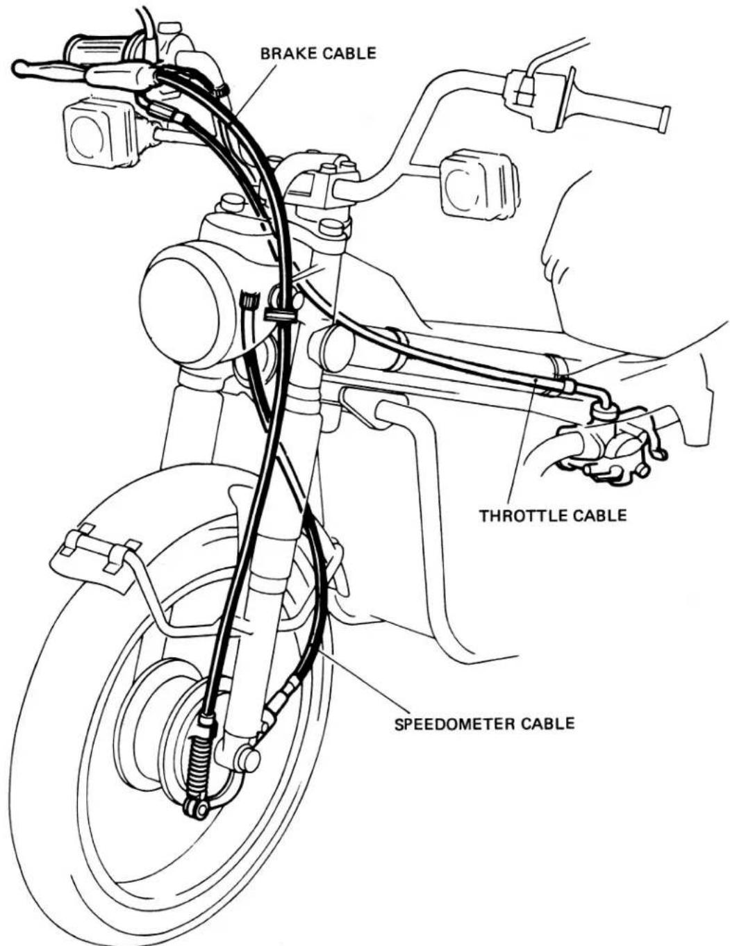
- WIRE HARNESS ROUTING
FRONT BRAKE
STOPLIGHT SWITCH
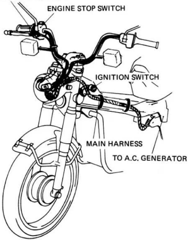
NOTE
Make sure that the battery cable is not pinched between the battery cover and frame.
RIGHT SIDE COVER
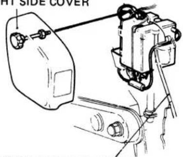
BATTERY BREATHER TUBE
REAR HARNESS
Clamp the harness to the back of the rear fender.
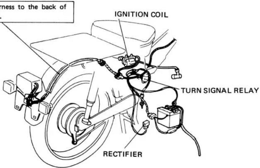
III. INSPECTION/ADJUSTMENT
1. ENGINE OIL CHANGE
Remove oil filler cap and drain plug after the engine is warm, and drain the oil. Install the drain plug, and check the sealing washer condition.
TORQUE: 2.0–3.5 kg-m
(14.5–25.3 ft-lbs)
Fill crankcase with the recommended oil.
OIL CAPACITY: 1.1 lit. (1.2 US qt, 1.0
Imp qt) approximately.
RECOMMENDED OIL:
Use HONDA 4-STROKE OIL or equivalent.
API SERVICE CLASSIFICATION: SE
VISCOSITY: SAE 10W-40
Reinstall the oil filler cap.
Start the engine and allow it to idle for 2–3 minutes.
Stop the engine, and make sure that the oil level is at the upper level mark with the vehicle in an upright position, and that there are no oil leaks.
Other viscosities shown in the chart may be used when the average temperature in your riding area is within the indicated range.
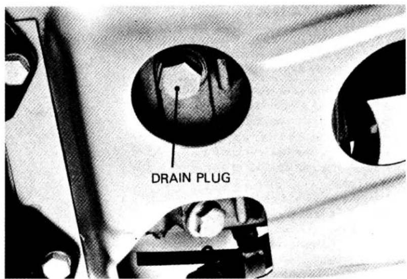
OIL VISCOSITIES
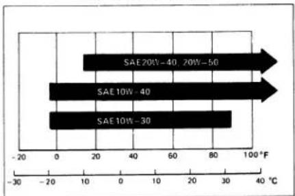
bar
| Category | Value (°C) | |---|---| | SAE 20W-40, 20W-50 | 20 | | SAE 10W-40 | 40 | | SAE 10W-30 | 30 |2. SPARK PLUG REPLACEMENT
Clean any dirt from around the spark plug base.
Disconnect the spark plug cap.
Remove and discard the spark plug.
Measure the new spark plug gap using a wire-type feeler gauge.
Adjust the plug gap by bending the side electrode carefully.
SPARK PLUG CAP: 0.6–0.7mm
(0.024-0.028 in)
With the spark plug washer attached, thread the spark plug in by hand to prevent cross-threading.
Tighten the spark plug 12 turn with a spark plug wrench to compress the washer.
Connect the spark plug cap.
RECOMMENDED SPARK PLUG
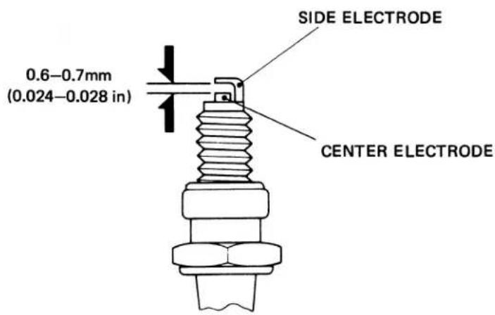
| UsageManufacturer | For cold climate(below 5°C, 41°F) | Standard | For extendedhigh speed riding | |
| USAModel | ND | X22ES-U | X24ES-U | X27ES-U |
| NGK | D7EA | D8EA | D9EA | |
| CANADAModel | ND | X22ESR-U | X24ESR-U | X27ESR-U |
| NGK | DR7ES | DR8ES-L | DR8ES |
3. VALVE CLEARANCE
NOTE
Inspect and adjust valve clearance while the engine is cold (below 35°C, 95°F).
Remove the left crankshaft hole cap, timing mark hole cap and adjuster caps.
Turn the crankshaft counterclockwise and align the "T" mark on the rotor with the index mark on the left crankcase cover. The piston must be at TDC of the compression stroke.
Measure the intake and exhaust valve clearances with a 0.05mm (0.002 in) feeler gauge. Insert the feeler gauge between the valve adjusting screw and valve stem.
Adjust by loosening the lock nut and turning the adjusting screw until there is a slight drag on the feeler gauge.
Hold the adjusting screw and tighten the lock nut.
Recheck the valve clearance.
Reinstall the removed parts in the reverse order of disassembly.
4. CONTACT BREAKER POINTS
Remove the crankshaft hole cap and point cover.
Clean the point contact surfaces with an electrical contact cleaner to remove any oil film or dirt. If the contact surfaces are level but grayish in color or are slightly pitted, file them lightly with a point file. If the points have a noticeable transfer of metal from one surface to the other, have evidence of heavy arcing, or are worn at an angle, they should be replaced.
Rotate the crankshaft counterclockwise and measure the maximum point gap with a feeler gauge.
POINT GAP: 0.3–0.4mm (0.012–0.016 in)
Adjust by loosening the two point locking screws and moving the contact breaker plate to achieve the correct gap.
Tighten the locking screws and recheck the point gap.
Adjust the ignition timing after the point gap has been adjusted (page 153).
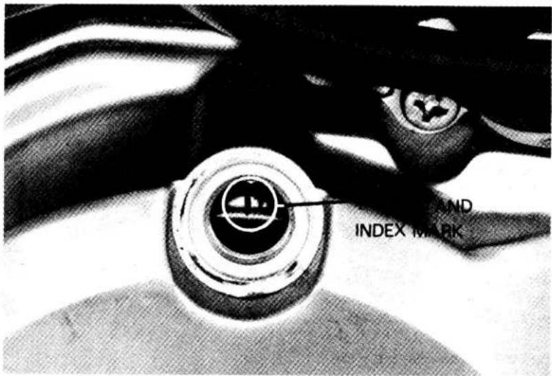
VALVE ADJUSTING WRENCH
No. 07908-0010000
VALVE CLEARANCE (IN/EX): 0.05mm (0.002 in)
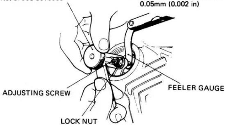
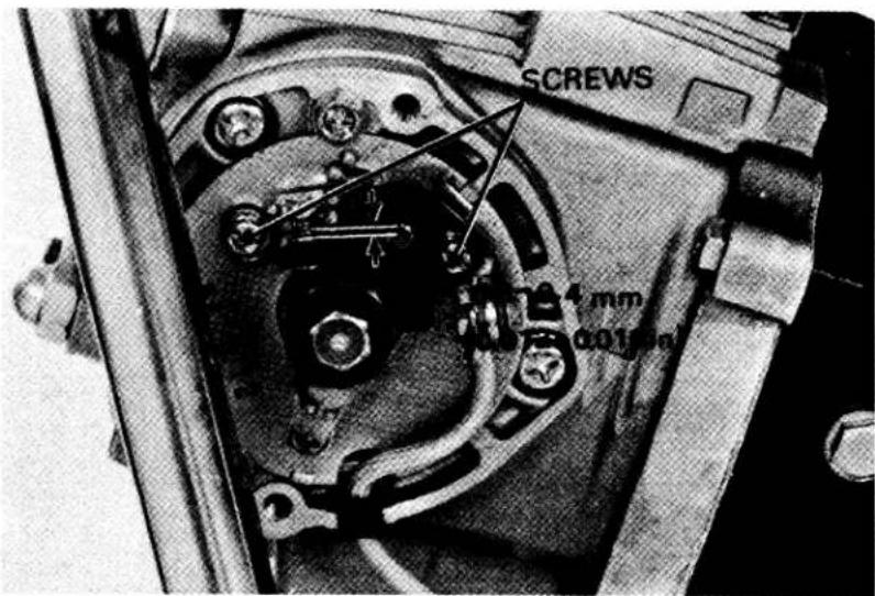
5. IGNITION TIMING
NOTE
Adjust the contact breaker point gap before this adjustment.
STATIC
Obtain a fully charged 6V battery and a continuity light (6V-3W).
Remove the crankshaft hole cap, timing mark hole cap and point cover.
Connect one lead of the continuity light to the contact breaker terminal, and the other lead to the fully charged battery positive (+) terminal. Ground the battery negative (−) terminal to the frame.
Rotate the crankshaft counterclockwise and align the "F" mark on the rotor with the index mark on the left crankcase cover. The timing is correct if the light goes out when both marks align.
If the timing is incorrect, loosen the contact breaker base plate locking screws.
Rotating the base plate clockwise will advance the ignition timing.
Rotating the base plate counterclockwise will retard the ignition timing.
Tighten the base plate locking screws. Recheck the ignition timing and point gap. Install the removed parts in the reverse order of disassembly.
DYNAMIC
Connect a tachometer and a stroboscopic timing light.
Remove the timing mark cap and start the engine and adjust the idle speed to 1,300 ± 100 rpm.
The timing is correct, if the "F" mark on the rotor aligns with the index mark on the left crankcase cover.
If necessary, adjust the ignition timing by removing the point cover and loosening the point base plate locking screws and turning the base plate.
Disconnect the timing light and tachometer and install the removed parts in the reverse order of disassembly.
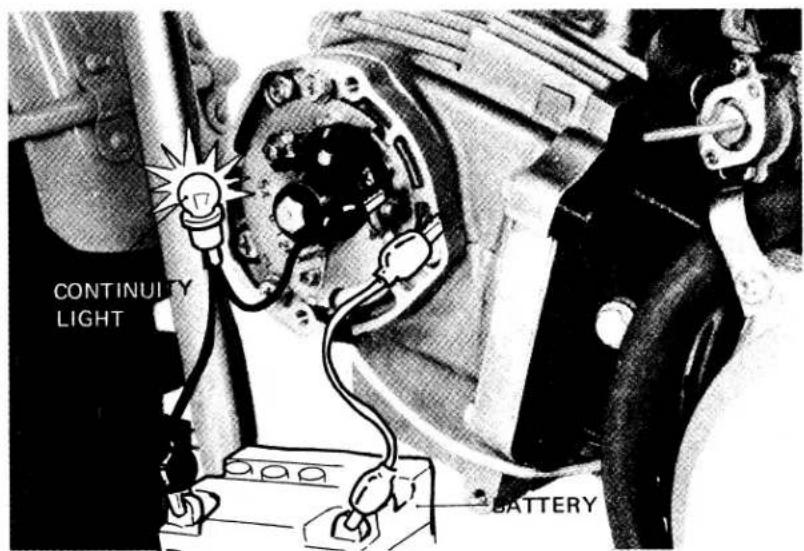
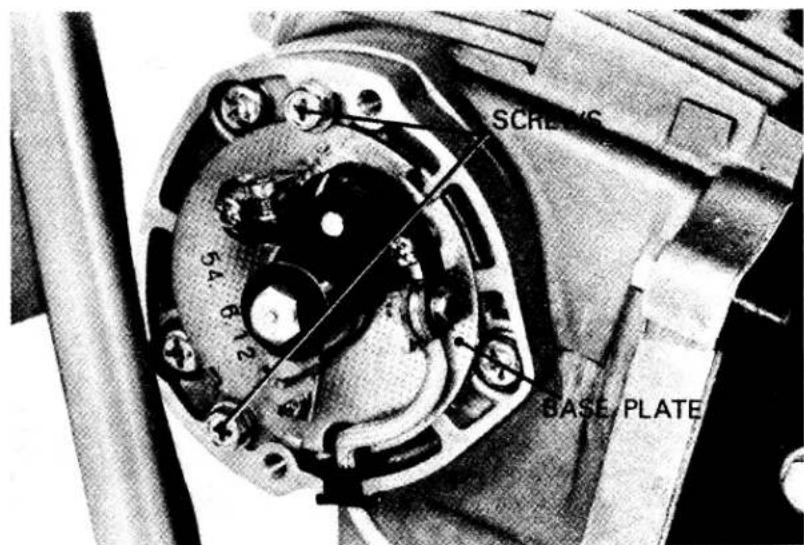
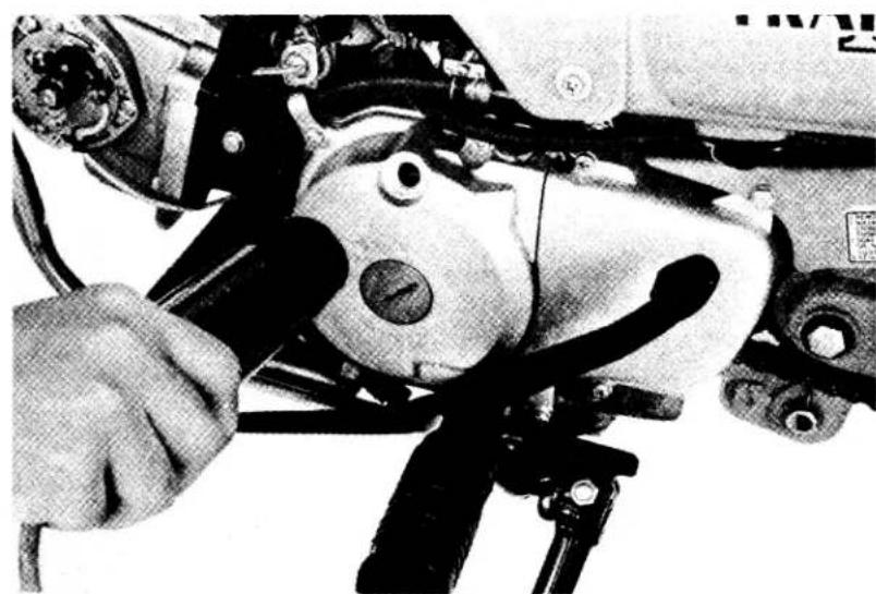
natural_image
Close-up of a mechanical assembly with hands operating a tool (no visible text or symbols)6. SPARK ADVANCER
NOTE
Before performing this test, check and adjust the ignition timing.
Remove the timing mark cap.
Connect a tachometer and a stroboscopic timing light.
Start the engine.
Make sure the index mark on the left crank-case cover is between the full-advance marks on the rotor at 3,400 rpm.
If not check the spark advancer operation.
7. CONTROL CABLE LUBRICATION
Disconnect the throttle and brake control cables at their upper ends. Thoroughly lubricate the cables and their pivot points with a commercially available cable lubricant.
8. BATTERY
Remove the frame right side cover.
Remove the battery holder and battery.
Check the fluid level.
Remove the battery cover and filler caps. Add distilled water to the upper level mark. The electrolyte level must be maintained between the upper and lower level marks. If sulfation forms or sediments (paste) accumulate on the bottom, replace the battery.
NOTE
Add distilled water only. Tap water will shorten the service life of the battery.
WARNING
The battery electrolyte contains sulfuric acid.
Protect your eyes, skin and clothing. In case of contact, flush thoroughly with water and call a doctor if your eyes were exposed.
Route the battery breather tube as shown in the diagram.
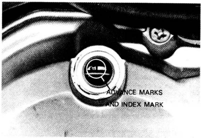
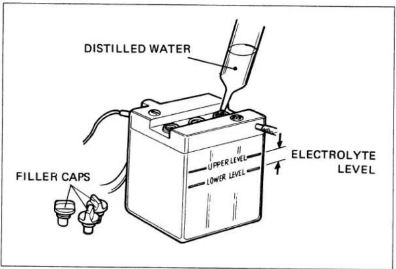
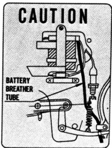
IV. ENGINE
1. CYLINDER HEAD/VALVES
For dis/assembly procedures and service information not described, refer to the base shop Manual.
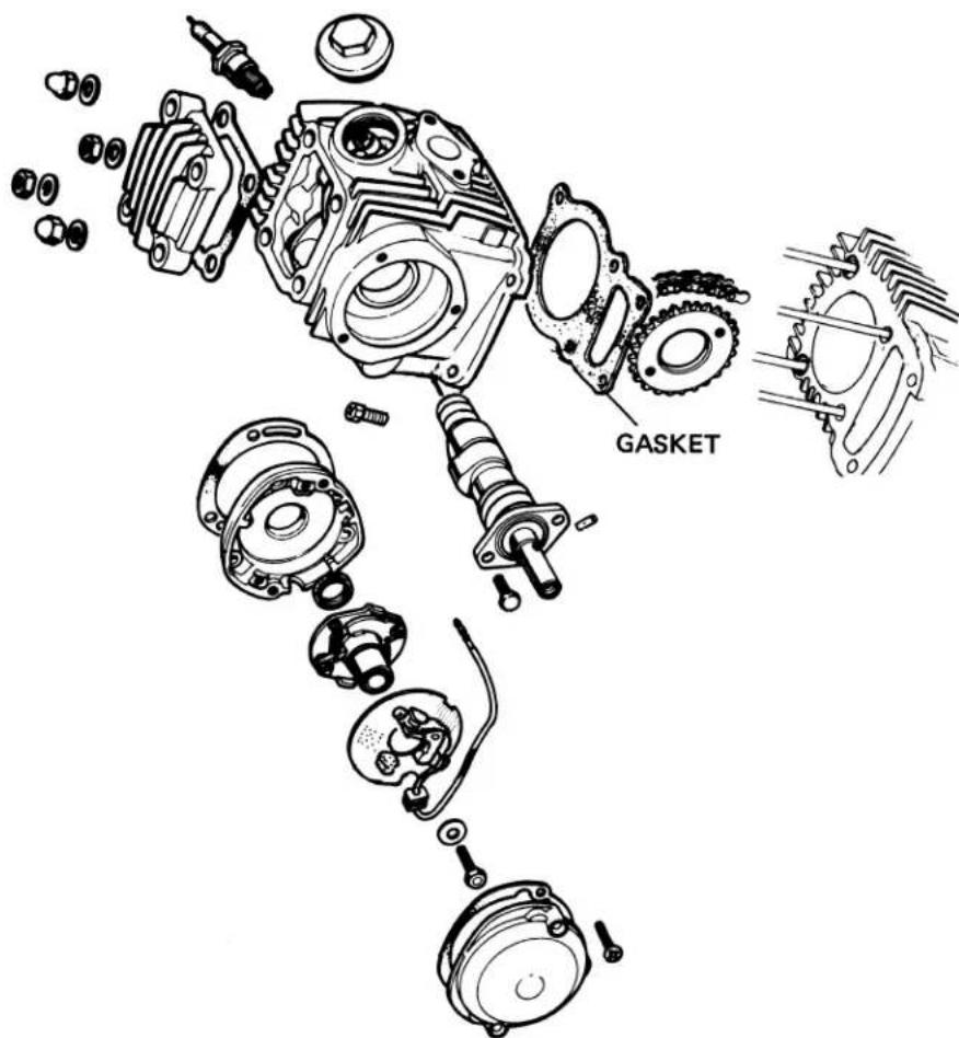
- CONTACT BREAKER POINT DIS/ASSEMBLY
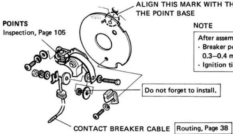
2. CYLINDER/PISTON
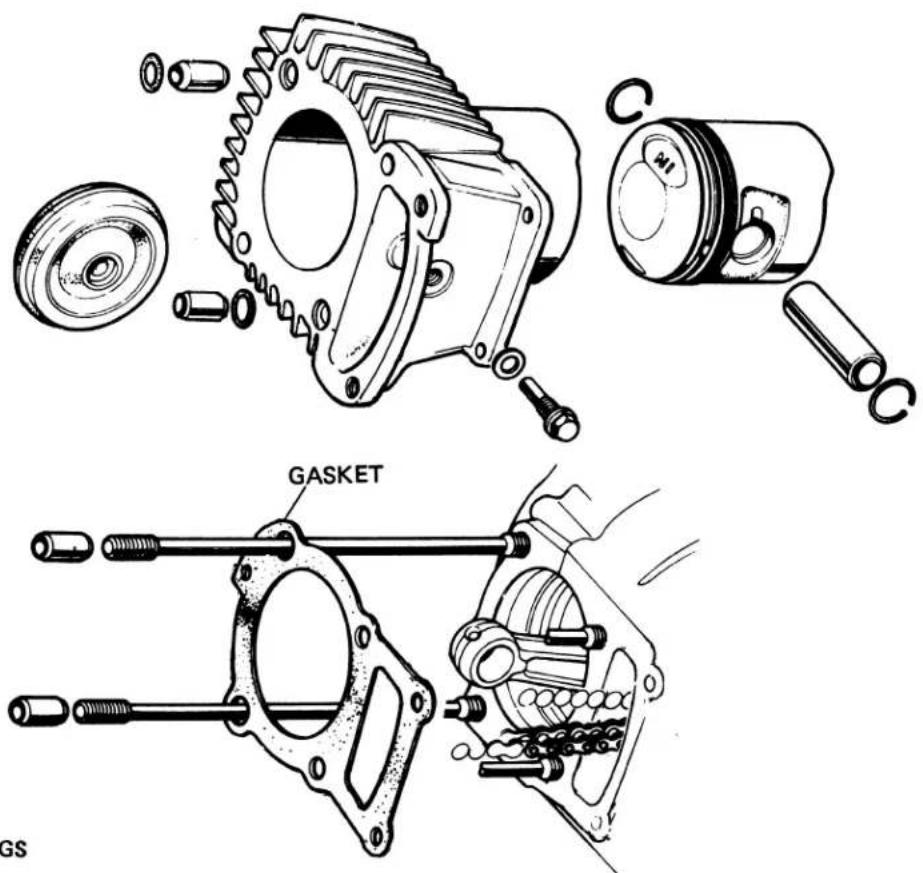
- PISTON RINGS
FACE THE MARKS UP
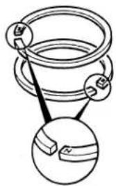
natural_image
Diagram of a mechanical component with two circular views showing internal structure (no text or symbols)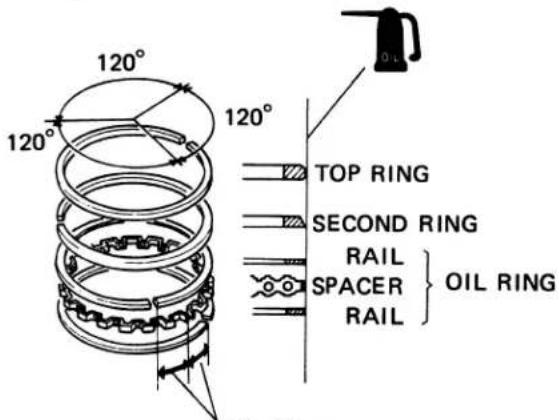
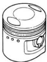
NOTE
- Clean the ring grooves and oil holes before installing the piston rings. When installing, be sure the rings do not bind in their grooves.
• Install the oil ring spacer first, then rails. Stagger oil ring end gap. -
Position 1st, 2nd, and oil rings so end gaps are 120 degrees apart and no gap is in line with the piston pin ends.
-
A.C. GENERATOR/CAM CHAIN TENSIONER
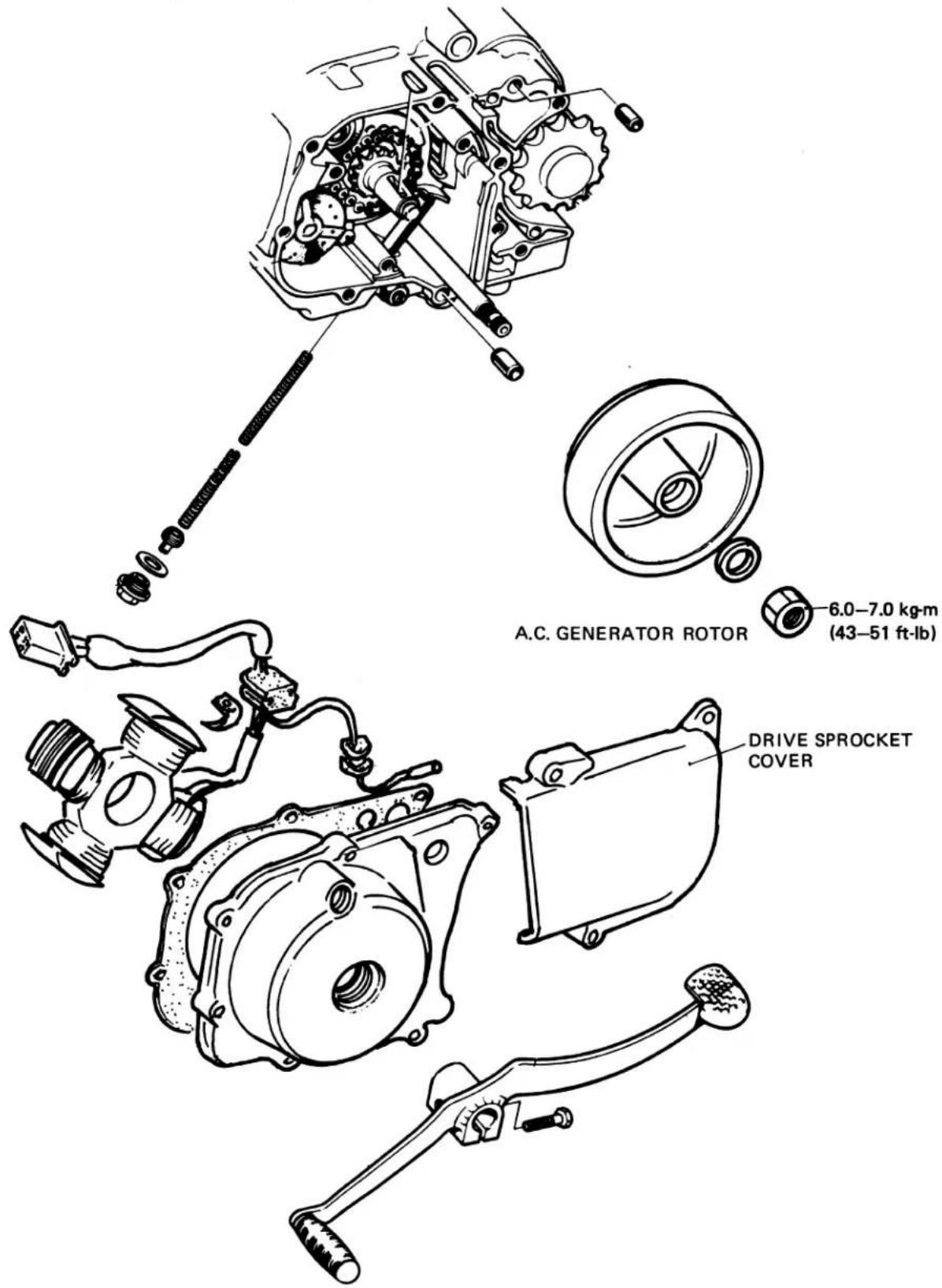
- A.C. GENERATOR REMOVAL Drain the oil from the engine. Disconnect the A.C. Generator wires. Remove the drive sprocket cover. Remove gearshift pedal.
Remove the left crankcase cover.
Remove the A.C. Generator rotor.
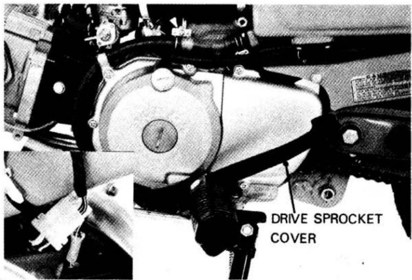
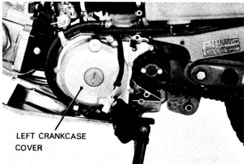
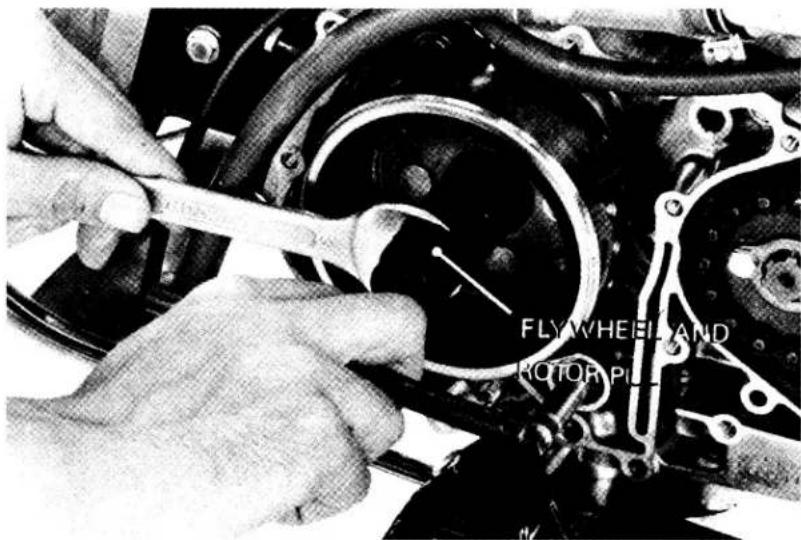
• CAM CHAIN TENSIONER REMOVAL
Remove the seal bolt, adjust bolt B, and tensioner spring A and B (See page 68)
Loosen the lock nut and adjusting bolt A. Remove the tensioner push rod.
Remove the tensioner set plate A and B. Remove the cam chain guide sprocket.
Remove the cam chain from the crankshaft sprocket and remove the cam chain tensioner.
• CAM CHAIN TENSIONER INSTALLATION
Install the cam chain tensioner in the reverse order of the removal.
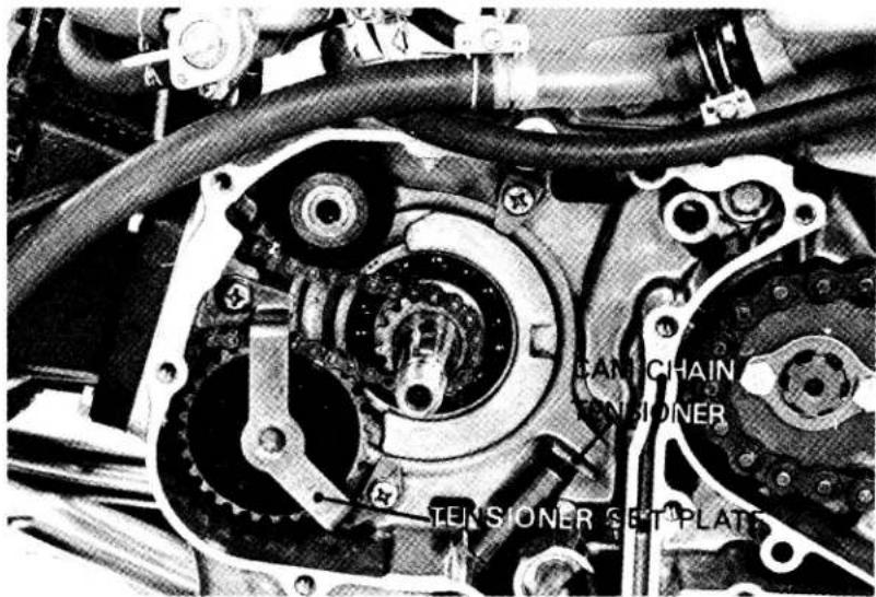
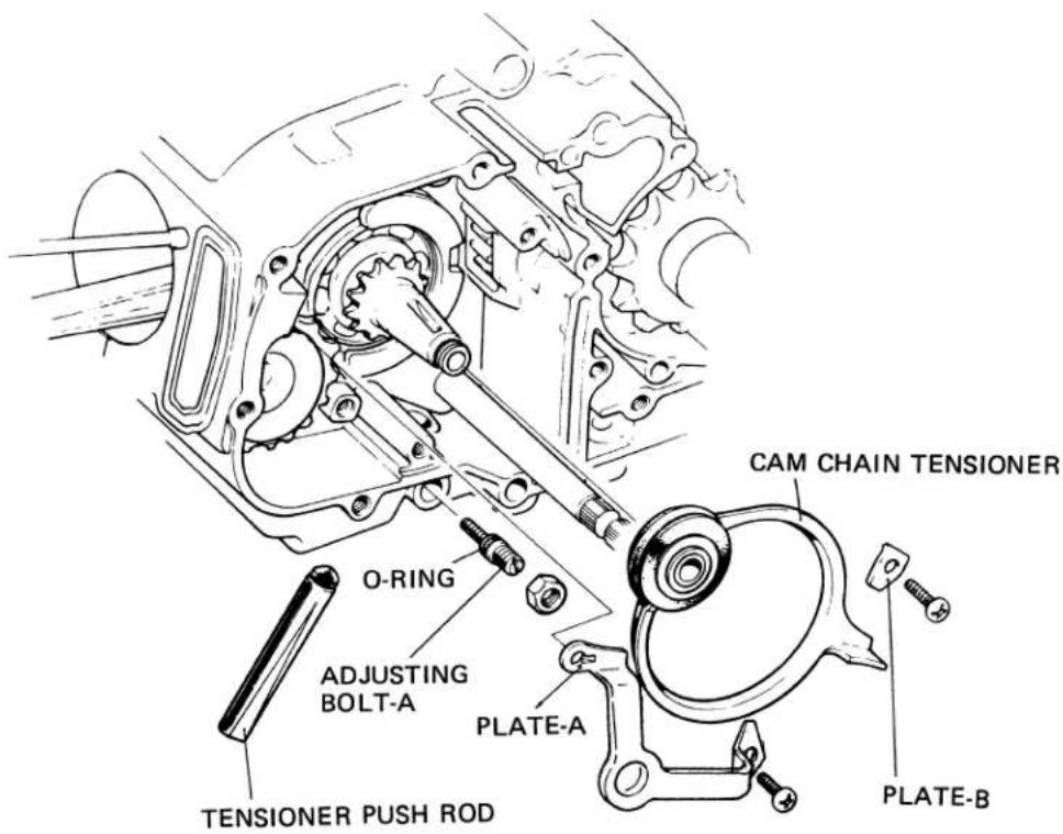
Place the cutout toward adjusting bolt A.
• NEUTRAL SWITCH INSTALLATION
Install the neutral switch onto the left crank-case.
Install the rubber seal on the switch.
Install the left crankcase cover.
Connect the neutral switch wire connector to the neutral switch as shown.
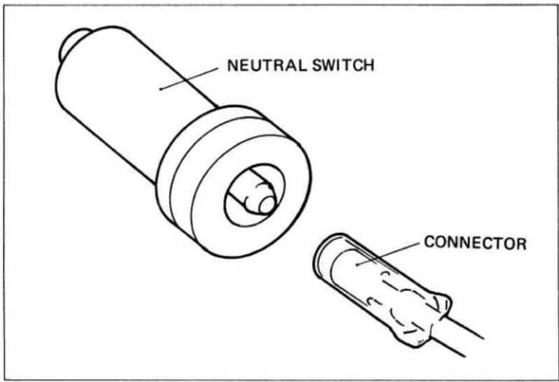
- STATOR COIL REMOVAL/INSTALLATION
Remove the drive sprocket cover.
Disconnect the stator wires.
Remove the gearshift pedal.
Remove the left crankcase cover.
Remove the stator coil.
Install the stator coil and wire holder as shown.
Install the left crankcase cover in the reverse order of the removal.
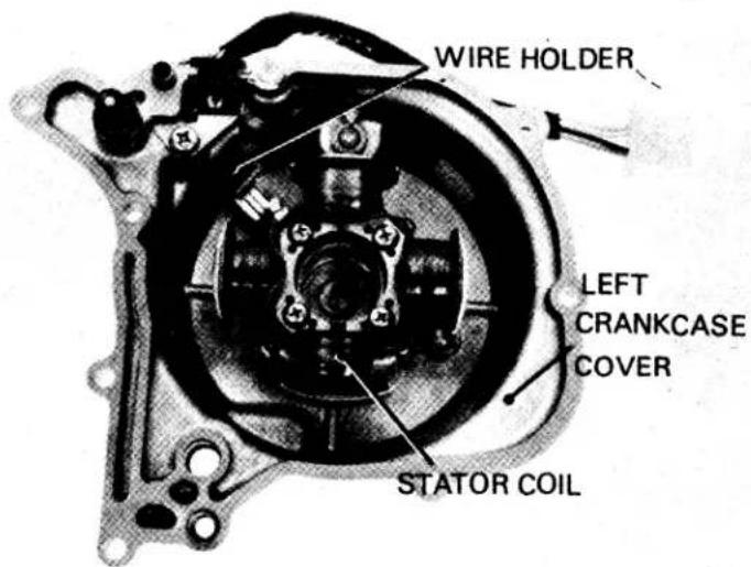
V. CARBURETOR
1. CARBURETOR SPECIFICATIONS
| Identification mark | PB21A |
| Main jet | #72 |
| Jet needle mark | 17D |
| Float level | 10.7 mm |
| Idle speed | 1300 ± 100 rpm |
| Pilot screw setting | See page 162 |

2. PILOT SCREW REMOVAL/INSTALLATION
NOTE
The pilot screw is factory pre-set and should not be removed unless the carburetor is overhauled.
Remove the carburetor.
Remove the float chamber.
Turn the pilot screw in and carefully count the number of turns before it seats lightly. Make a note of this to use as a reference when installing the pilot screw.
CAUTION
Damage to the pilot screw and seat will occur if the pilot screw is tightened against the seat.
Remove the pilot screw with the limiter cap attached.
CAUTION
Any forcible attempt to remove the pilot screw limiter cap will break the screw.
Inspect the pilot screw for wear and replace if necessary.
Install the pilot screw and return it to its original position as noted during removal. Perform pilot screw adjustment if a new pilot screw is installed.
NOTE
Do not install a limiter cap on a new pilot screw until after adjustment has been made (see below).
PILOT SCREW WITH LIMITER CAP
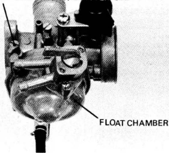
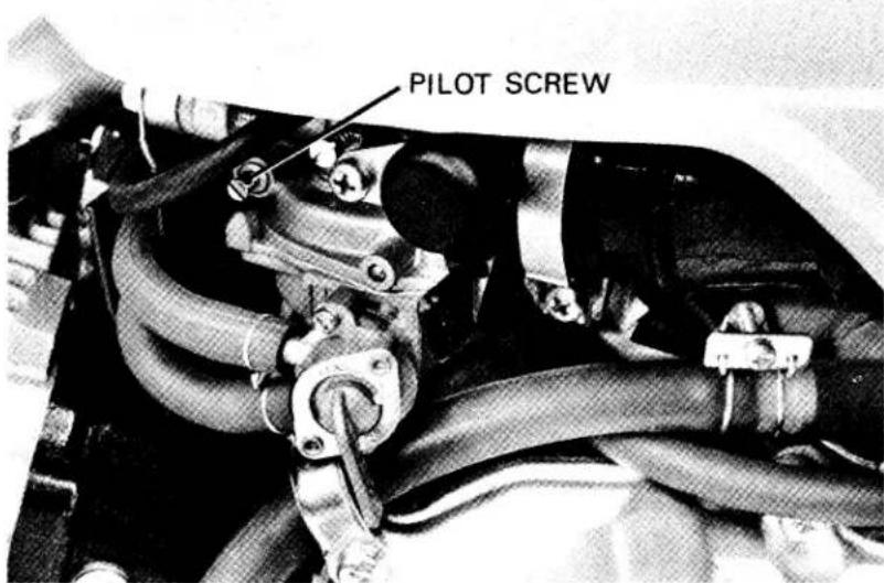
3. PILOT SCREW ADJUSTMENT
NOTE
· The pilot screw is factory pre-set and no adjustment is necessary unless the pilot screw is replaced (see removal above).
Turn the pilot screw clockwise until it seats lightly and back it out to the specification given.
This is an initial setting prior to the final pilot screw adjustment.
INITIAL OPENING: 1-1/2 TURNS OUT
CAUTION
Damage to the pilot screw and seat will occur it the pilot screw is tightened against the seat.
Warm the engine up to operating temperature. Stop and go driving for 10 minutes is sufficient.
Connect a tachometer.
Adjust the idle speed with the throttle stop screw.
IDLE SPEED: 1300 rpm
Turn the pilot screw in or out to obtain the highest engine speed.
Readjust the idle speed to 1300 ± 100 rpm, using the throttle stop screw.
• LIMITER CAP INSTALLATION
If the pilot screw has been replaced, a new limiter cap must be installed after pilot screw adjustment is completed.
After adjustment, cement the limiter cap over the pilot screw, using LOCTITE® #601 or equivalent. The limiter cap should be placed against its stop, preventing further adjustment the would enrich the fuel mixture (limiter cap position permits clockwise rotation and prevents counterclockwise rotation).
NOTE
A pilot screw limiter cap must be installed. It prevents misadjustment that could cause poor performance and increase emissions.
• HIGH ALTITUDE ADJUSTMENT
For sustained High altitude operation (above 2,000 m/6,500 ft) install a #70 main jet and readjust idle speed.
(1) Remove the carburetor from the engine and remove the float bowl.
(2) Replace the standard #72 main jet with the high altitude #70 main jet.
(3) Assemble and install the carburetor.
(4) Adjust idle speed to 1300 ± 100 rpm., using the throttle stop screw.
CAUTION
Sustained operation at altitudes lower than 1,500m (5,000 ft) with the high altitude main jet installed may cause engine overheating and damage. For sustained operation below 1,500 m (5,000 ft), reinstall the standard main jet and readjust idle speed.
| Standard 2000m (6500ft) max. | High altitude type. 1500m (5000ft) min. | |
| Main jet Idle speed Pilot screw opening | #72 1300 ±100rpm Factory pre-set | #70 ← ← |
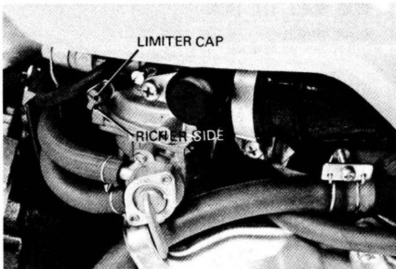
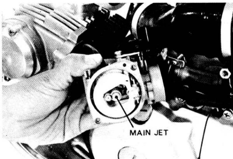
VI. REAR WHEEL/TAIL LIGHT
1. REAR WHEEL
- REAR WHEEL DISASSEMBLY/ASSEMBLY
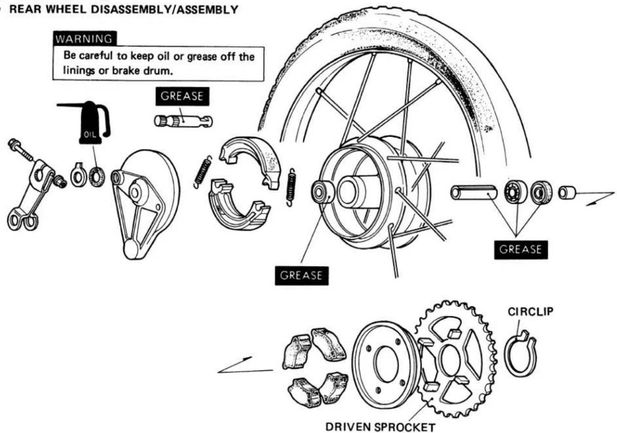
- REAR WHEEL BEARING INSTALLATION
Drive the right bearing in first, then install the distance collar and drive in the left bearing.
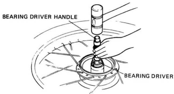
NOTE
- Drive the bearing squarely, being careful not to allow it to tilt.
- Install the bearing with the shield end outward.
2. REAR SHOCK ABSORBER
3. TAILLIGHT AND TURN SIGNAL
- LENS REMOVAL/INSTALLATION
Remove the lens by pulling the top edge forward.
Install the lens by pressing it in, bottom edge first, then top.
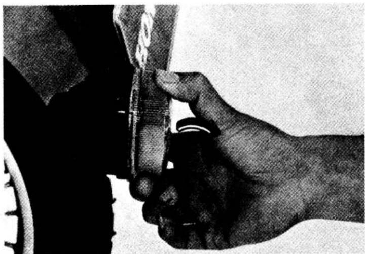
natural_image
Close-up of a hand adjusting a tire component, no visible text or symbolsLOCK NUT
Before installing the nut, apply sealant to the threads.
STOP RUBBER
REAR SHOCK ABSORBER SPRING
Install the spring with the narrow pitch end up.
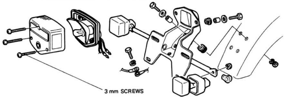
CAUTION
Overtightening the screws may damage the lens.
VII. ELECTRICAL
1. BATTERY CHARGING SYSTEM
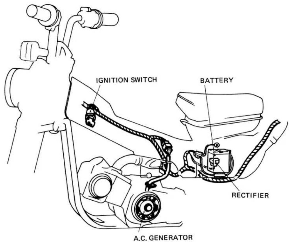
- DIAGRAM
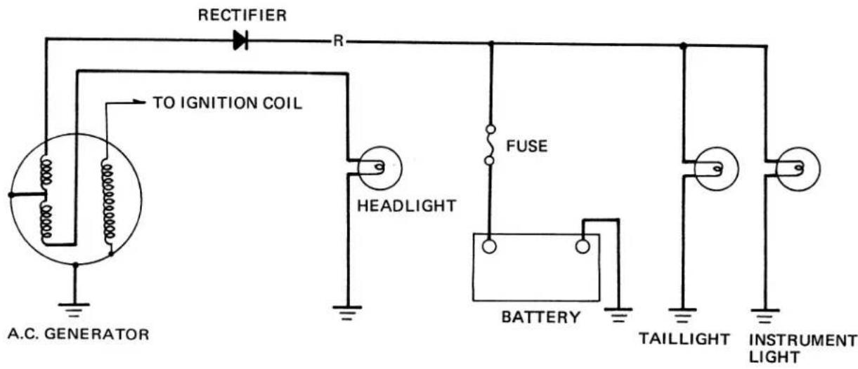
- CHARGING TEST
Connect a tachometer. Turn high beam on.
Connect the tester as shown below and run the engine at the following speeds:
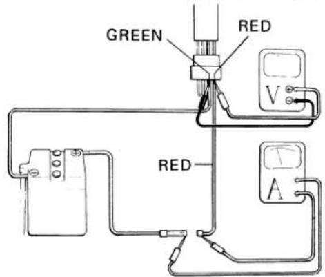
2,500 rpm .... .Charging should start (6.8V min.)
5,000 rpm .....0.8A min. (8.7V min.)
SPECIFIC GRAVITY OF BATTERY ELECTROYTE:
1.260-1.280 [at 20°C (68°F)]
NOTE
Raise the engine speed gradually and note the exact current and voltage indicated on the meters. Do not allow the needle of the meter to swing beyond the limit of needle travel.
• STATOR COIL CONTINUITY TEST
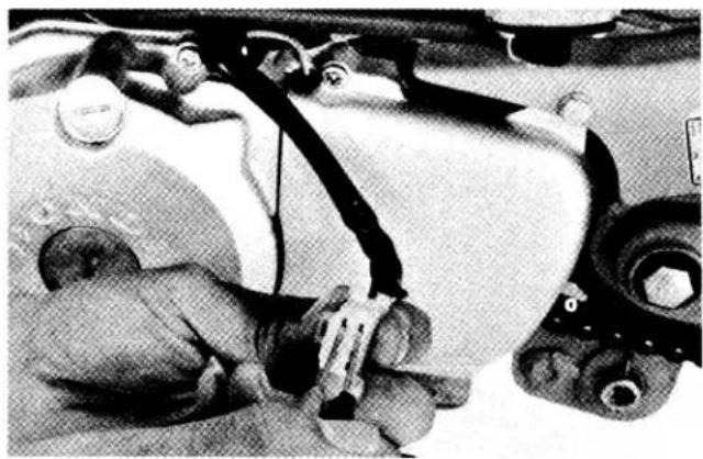
natural_image
Close-up of a car's engine compartment with visible wiring and valve (no text or symbols)| Black/white | Yellow | White |
The coil is normal if there is continuity between circuits (o-o).
Refer to stator coil replacement on page 161, if necessary.
Rectifier Test
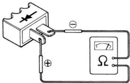
The rectifier is normal if there is continuity only in one direction. Replace the rectifier if there is continuity in the reverse direction.
NOTE
The direction of continuity depends on your tester's polarity.
2. IGNITION SYSTEM
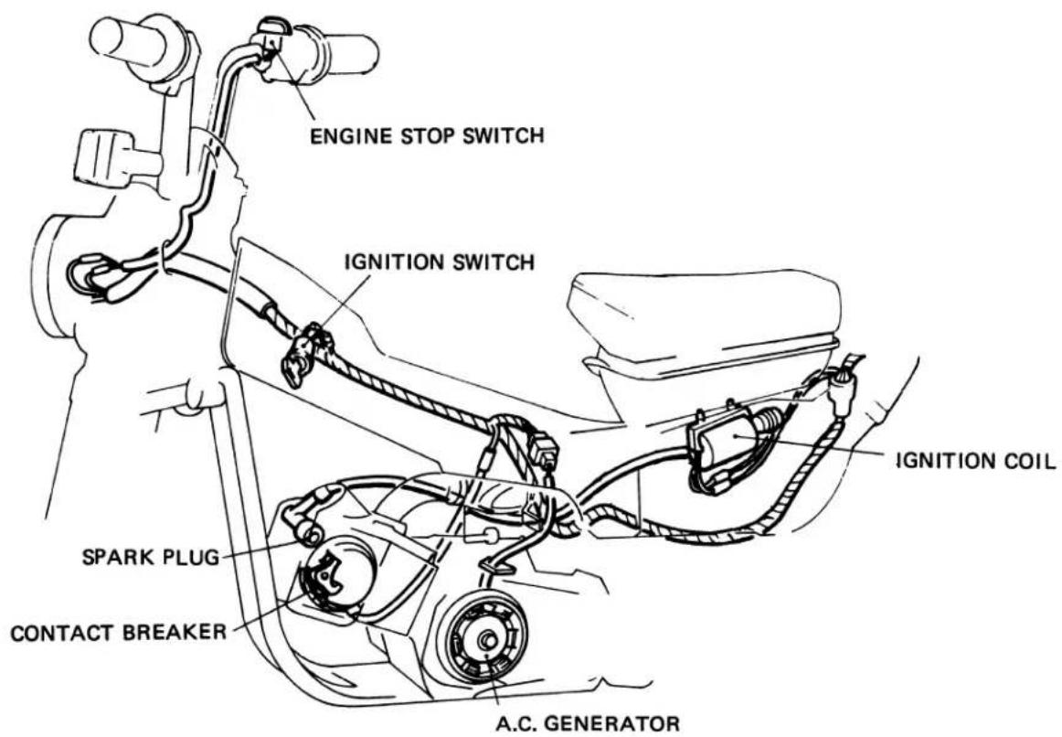
- DIAGRAM
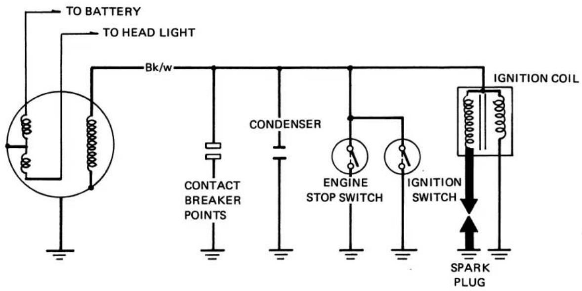
3. SWITCHES
- IGNITION SWITCH
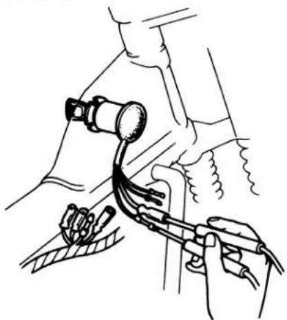
natural_image
Line drawing of a medical procedure involving a catheter and tubing (no text or symbols)| switch\wire color | Red | Black | Green | Black/White |
The switch is normal if there is continuity between terminals (o-o).
● HORN, HEADLIGHT DIMMER, ENGINE STOP SWITCH
Remove the headlight, disconnect the switch leads and check for continuity. The switch is normal if there is continuity between terminals (o-o).
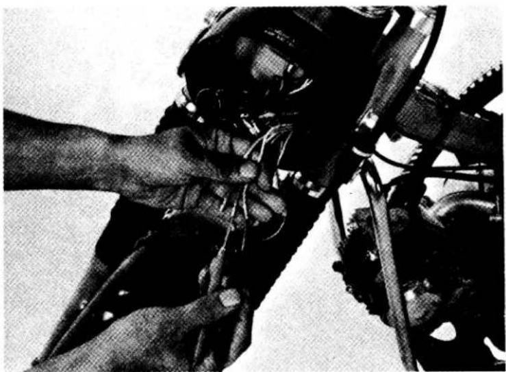
natural_image
Black-and-white photo of a person operating a robotic arm with visible wiring and mechanical components (no text or symbols)- HORN SWITCH
| switch\wire color | Light Green | Green |
The switch is normal if there is continuity between terminals (o-o).
• HEADLIGHT DIMMER SWITCH
| Switch\Wire color | Blue/White | Blue | White |
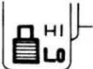 | |||
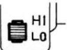 | |||
 |
The switch is normal if there is continuity between terminals (o-o).
- ENGINE STOP SWITCH
| Switch\Wire color | Green | Black/White |
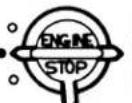 OFFRUNOFF OFFRUNOFF | ||
 OFFRUNOFF OFFRUNOFF |
The switch is normal if there is continuity between terminals (o-o).
VIII. WIRING DIAGRAM
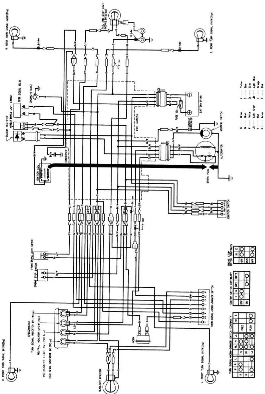
0030Z-459-6700
INTRODUCTION
This 1981 Shop Manual Addendum contains information for the 1981 CT110. Refer to the base shop manual and the 1980 CT110 Addendum for procedures and service data not included in this addendum.
ALL INFORMATION, ILLUSTRATIONS, DIRECTIONS AND SPECIFICATIONS INCLUDED IN THIS PUBLICATION ARE BASED ON THE LATEST PRODUCT INFORMATION AVAILABLE AT THE TIME OF APPROVAL FOR PRINTING. HONDA MOTOR CO., LTD. RESERVES THE RIGHT TO MAKE CHANGES AT ANY TIME WITHOUT NOTICE AND WITHOUT INCURRING ANY OBLIGATION WHATEVER.
NO PART OF THIS PUBLICATION MAY BE REPRODUCED WITHOUT WRITTEN PERMISSION.
HONDA MOTOR CO., LTD.
Service Publications Office
CONTENTS
- SPECIFICATIONS ..... 172
- LUBRICATION SYSTEM ..... 172
- AUXILIARY TRANSMISSION ..... 173
- A.C. GENERATOR/CAM CHAIN TENSIONER 176
- CARBURETOR 178
- CABLE AND HARNESS ROUTING ..... 180
- BATTERY 182
- TAILLIGHT AND TURN SIGNALS ..... 182
- WIRING DIAGRAM ..... 183
1. SPECIFICATIONS
The specifications below are only those which are new for 1981.
See pages 142 - 146 for other CT110 specifications which apply to the 1981 model.
| Items | Specifications | ||
| Dry Weight | 92.5 kg (203.5 lbs) | ||
| Engine Dry Weight | 24.9 kg (54.9 lbs) | ||
| Pilot Screw Setting | See page 179 | ||
| Idle Speed | 1,500 ± 100 rpm | ||
| Gear Ratio | I | High Range | 2.538 : 1 Low Range |
| II | 1.611 : 1 | ||
| III | 1.190 : 1 | ||
| IV | 0.958 : 1 | ||
2. LUBRICATION SYSTEM
• LUBRICATION CIRCUIT DIAGRAM
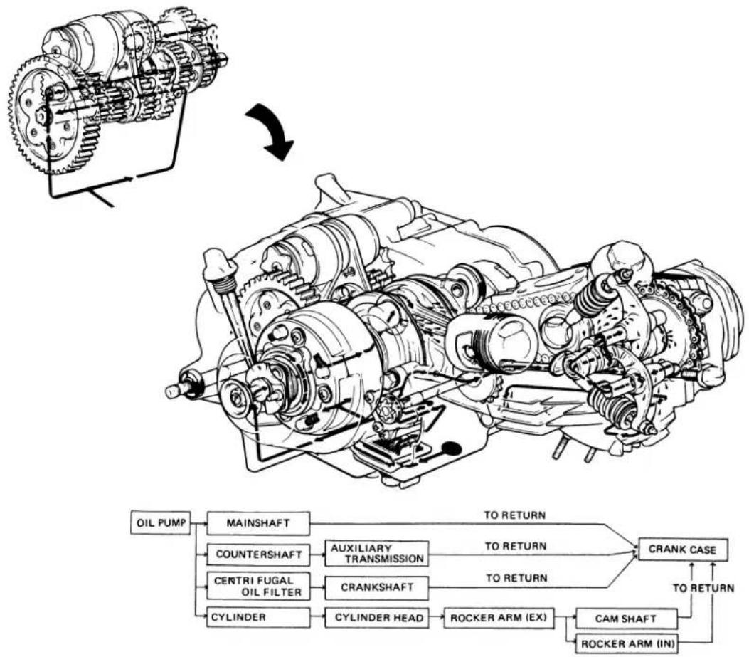
flowchart
graph TD
    A["Oil Pump"] --> B["Mainshaft"]
    B --> C["AUXILIARY TRANSMISSION"]
    C --> D["TO RETURN"]
    D --> E["CRANK CASE"]
    E --> F["TO RETURN"]
    F --> G["CYLINDER"]
    G --> H["CYLINDER HEAD"]
    H --> I["ROCKER ARM (EX)"]
    I --> J["TO RETURN"]
    J --> K["CAM SHAFT"]
    K --> L["ROCKER ARM (IN)"]
    L --> M["TO RETURN"]
    M --> N["CENTRI FUGAL OIL FILTER"]
    N --> O["CRANKSHAFT"]
    O --> P["TO RETURN"]
    P --> Q["TO RETURN"]
    Q --> R["POINTERSHRAFT"]
    R --> S["TO RETURN"]
    S --> T["POINTERSHRAFT"]
    T --> U["TO RETURN"]
    U --> V["POINTERSHRAFT"]
3. AUXILIARY TRANSMISSION
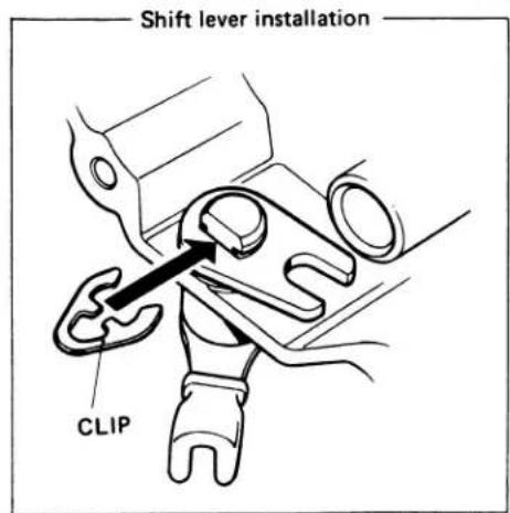
a. DISSASEMBLY/ASSEMBLY
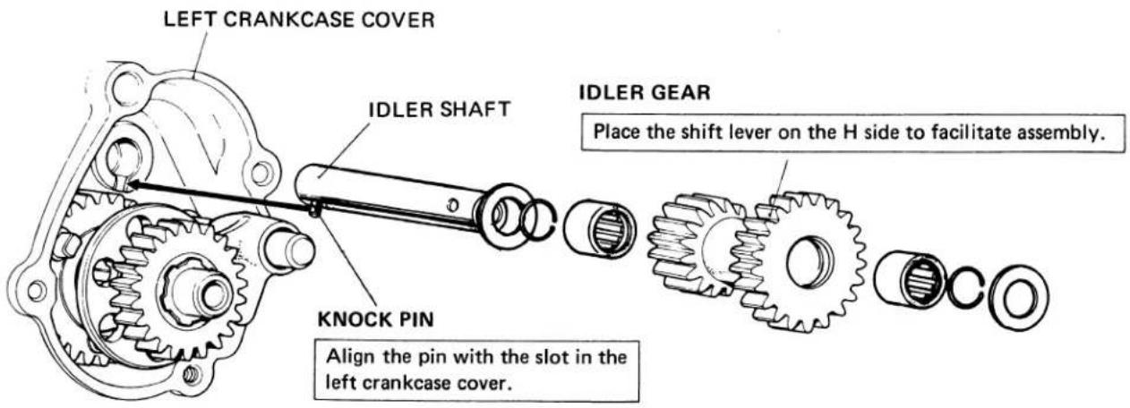
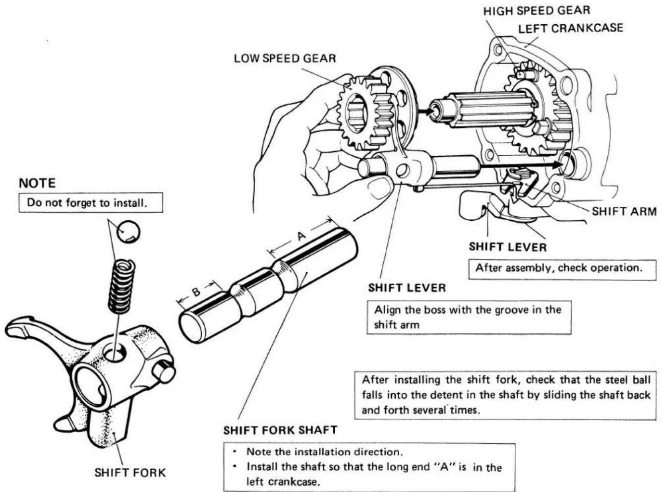
b. INSPECTION
• IDLER GEAR
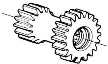
natural_image
Technical line drawing of a gear and shaft assembly (no text or symbols)Make sure that the bearings rotate smoothly and are in good condition.
• IDLER SHAFT O.D.

natural_image
Line drawing of a micrometer caliper tool (no text or symbols present)| Standard | Service Limit |
| 13.000–12.989 mm(0.5118–0.5114 in) | 12.979 mm(0.5110 in) |
- GEARS
CHECK FOR WEAR OR DAMAGE
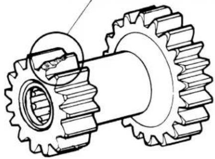
natural_image
Technical line drawing of a gear assembly with no visible text or symbolsCHECK FOR WEAR OR DAMAGE
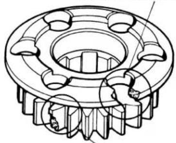
natural_image
Technical line drawing of a mechanical gear assembly (no text or symbols)CHECK FOR WEAR OR DAMAGE
- SHIFT FORK
WEAKNESS OR BREAKAGE
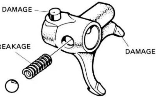
4. A.C.GENERATOR/CAM CHAIN TENSIONER
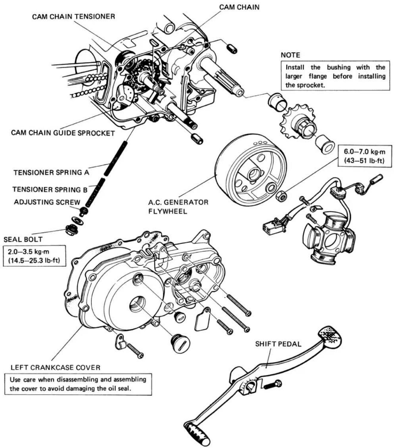
• A.C. GENERATOR REMOVAL
Drain the oil from the engine.
Disconnect the A.C. Generator wires.
Loosen the foot peg bracket bolts.
Remove gearshift pedal.
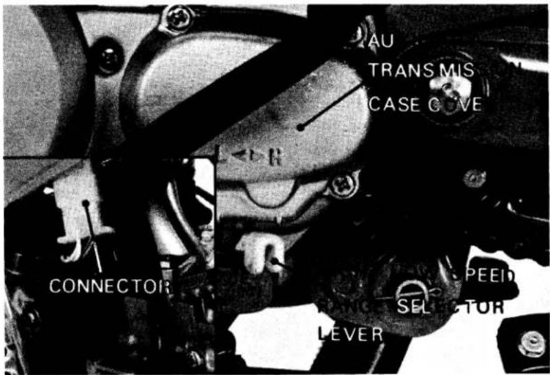
Remove the auxiliary transmission case cover and gears.
Remove the left crankcase cover.
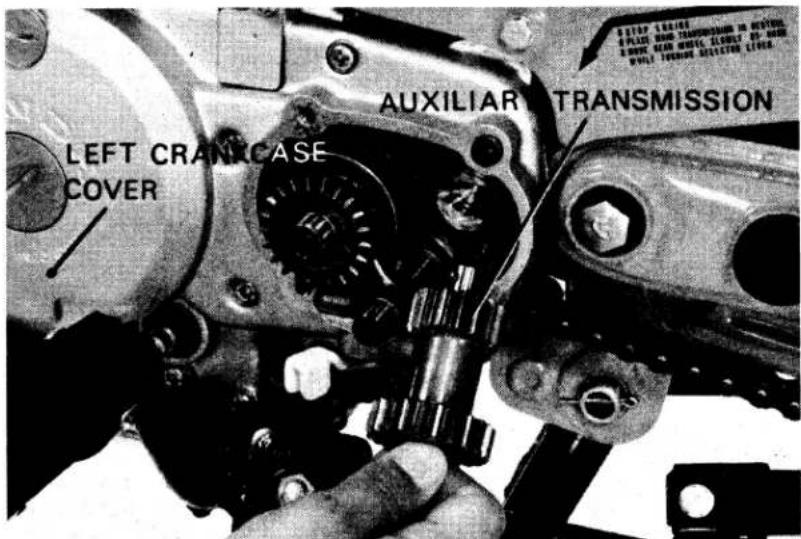
Remove the A.C. Generator rotor using the flywheel and rotor puller.
FLYWHEEL AND ROTER PULLER
(T/N 07933-0010000)
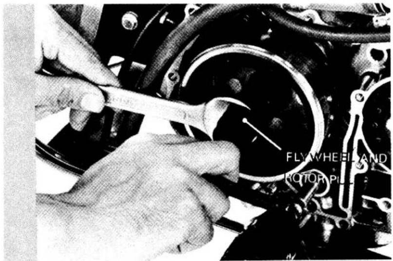
5. CARBURETOR
• CARBURETOR SPECIFICATIONS
| Identification mark | PB21A |
| Main jet | #72 |
| Jet needle mark | 17D |
| Float level | 10.7 mm |
| Idle speed | 1500 ± 100 rpm |
| Pilot screw setting | See page 179 |
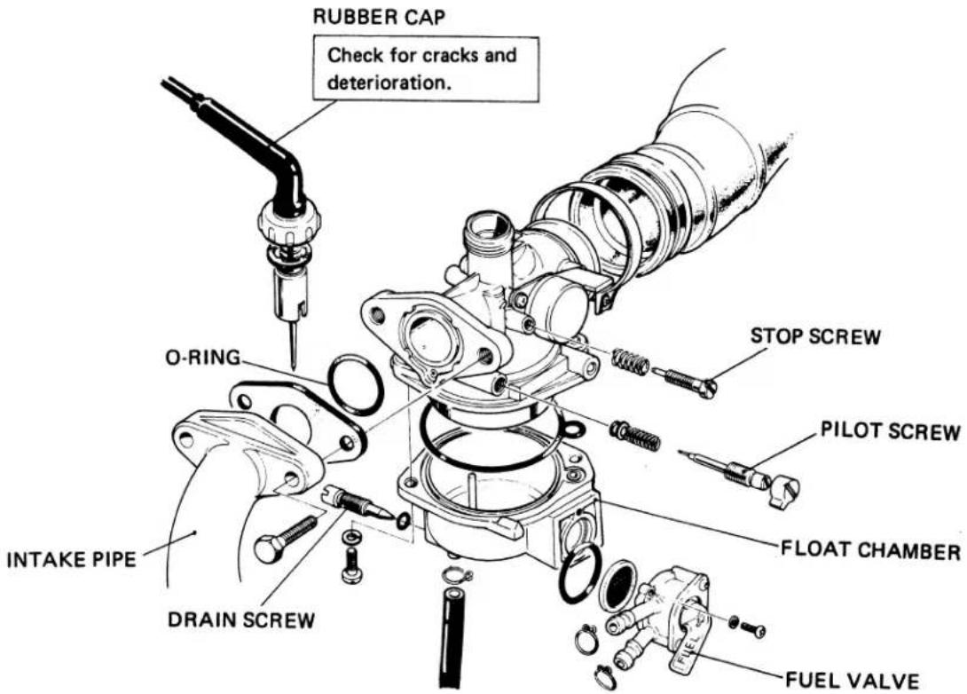
• PILOT SCREW ADJUSTMENT
NOTE
- The pilot screw is factory pre-set and no adjustment is necessary unless the pilot screw is replaced. - Refer to page 162 for pilot screw removal/installation.
Turn the pilot screw clockwise until it seats lightly and back it out to the specification given.
This is an initial setting prior to the final pilot screw adjustment.
INITIAL OPENING: 1-1/2 TURNS OUT
CAUTION
Damage to the pilot screw and seat will occur if the pilot screw is tightened against the seat.
Warm the engine up to operating temperature. Stop and go driving for 10 minutes is sufficient.
Connect a tachometer.
Adjust the idle speed with the throttle stop screw to 1500 rpm
Turn the pilot screw in or out to obtain the highest engine speed.
Readjust the throttle stop screw to obtain the specified idle speed.
IDLE SPEED: 1500 ± 100 rpm
• HIGH ALTITUDE ADJUSTMENT
For sustained High altitude operation (above 2,000 m/6,500 ft) install a #70 main jet and readjust idle speed.
(1) Remove the craburetor from the engine and remove the float bowl.
(2) Replace the standard #70 main jet.
(3) Assemble and install the carburetor.
(4) Adjust idle speed to 1500 ± 100 rpm., using the throttle stop screw.
CAUTION
Sustained operation at altitudes lower than 1,500m (5,000 ft) with the high altitude main jet installed may cause engine overheating and damage. For sustained operation below 1,500 m (5,000 ft), reinstall the standard main jet and readjust idle speed.
| Standard 2000m (6500ft) max. | High altitude type. 1500m (5000ft) min. | |
| Main jet Idle speed Pilot screw opening | #72 1500 ± 100rpm Factory pre-set | #70 ← ← |
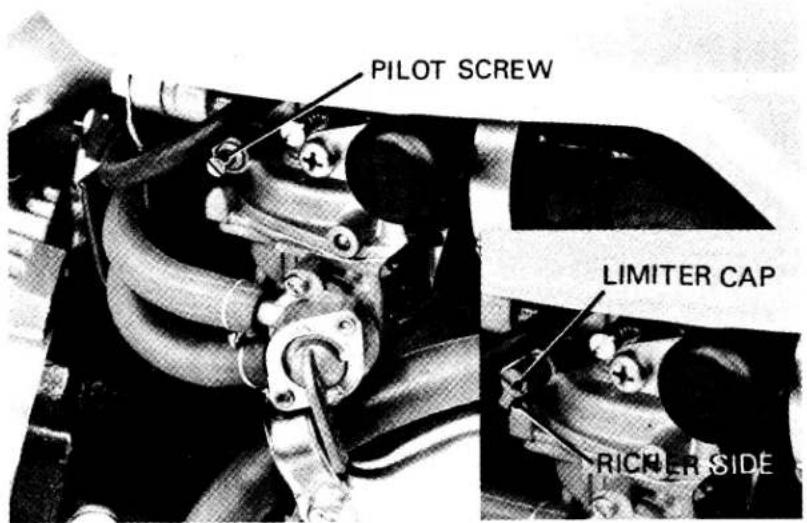
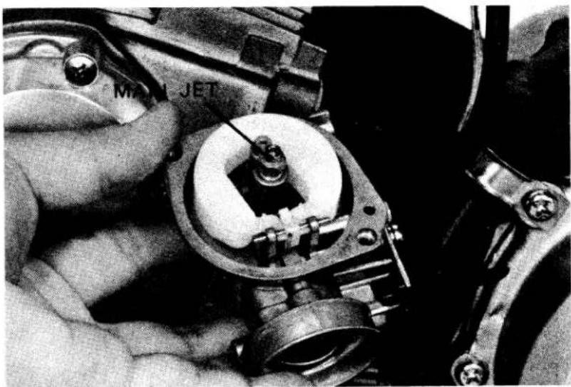
natural_image
Close-up of a hand using a mechanical tool to adjust a component, no visible text or symbols6. CABLE AND HARNESS ROUTING
- CABLE ROUTING
Route the brake, throttle and speedometer cables as shown.
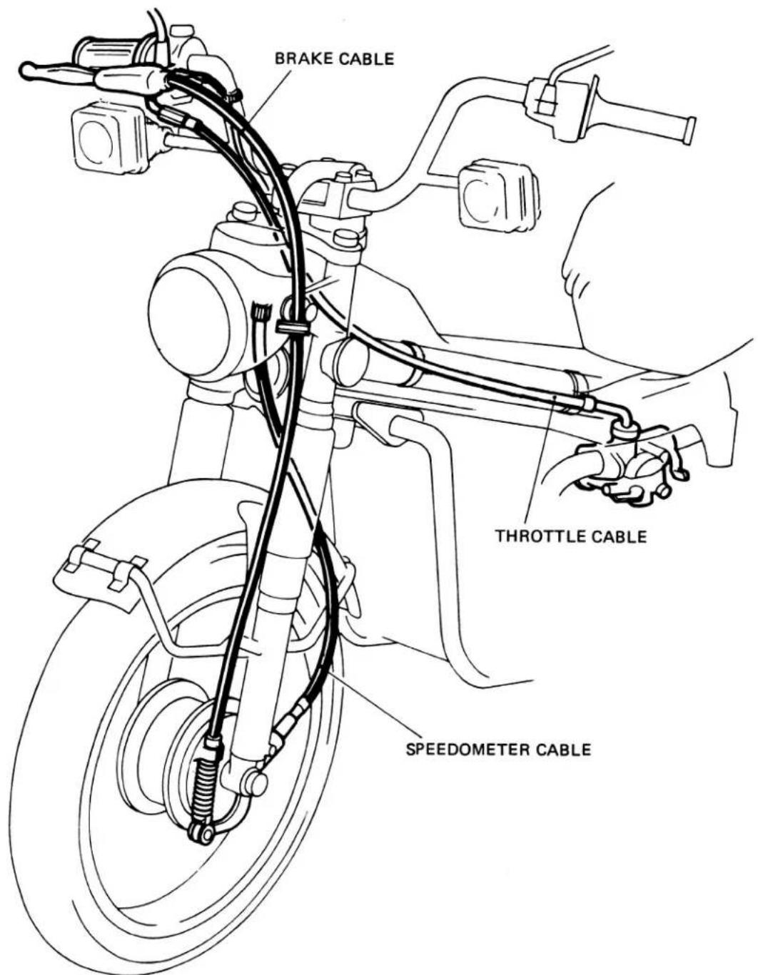
- WIRE HARNESS ROUTING
FRONT BRAKE
STOPLIGHT SWITCH
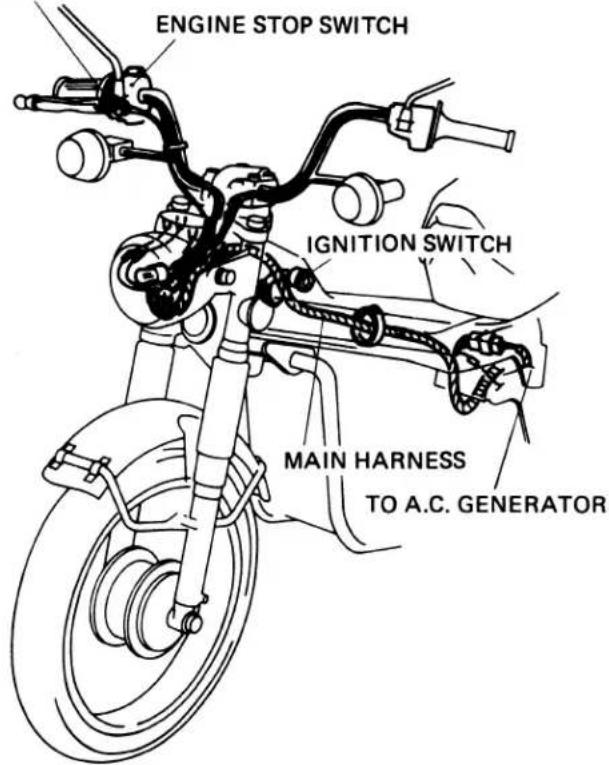
NOTE
Make sure that the battery cable is not pinched between the battery cover and frame.
RIGHT SIDE COVER
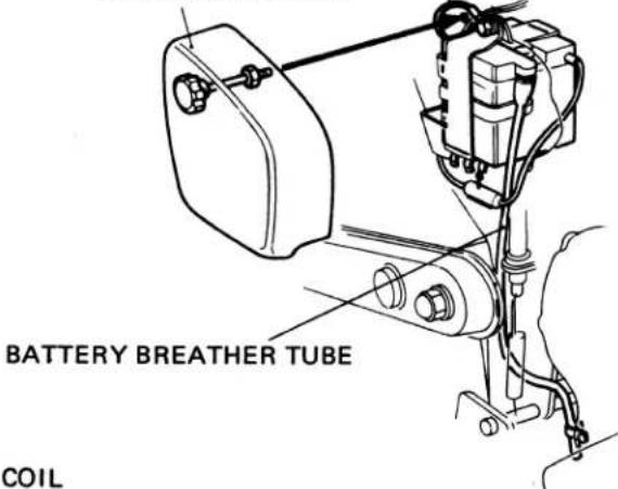
REAR HARNESS
Clamp the harness to the back of the rear fender.
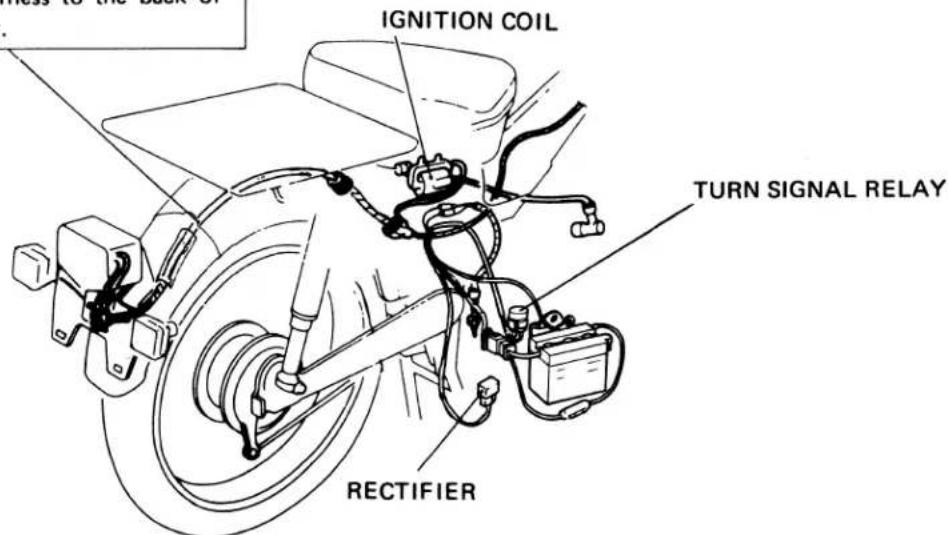
7. BATTERY
Remove the frame right side cover.
Remove the battery holder and battery.
Check the fluid level.
Remove the battery cover and filler caps.
Add distilled water to the upper level mark.
The electrolyte level must be maintained between the upper and lower level marks. If sulfation forms or sediments (paste) accumulate on the bottom, replace the battery.
NOTE
Add distilled water only. Tap water will shorten the service life of the battery,
WARNING
The battery electrolyte contains sulfuric acid.
Protect your eyes, skin and clothing. In case of contact, flush thoroughly with water and call a doctor if your eyes were exposed.
CAUTION
When checking battery electrolyte level or adding distilled water, make sure the breather tube is connected to the battery breather outlet.
8. TAILLIGHT AND TURN SIGNALS
- LENS REMOVAL/INSTALLATION
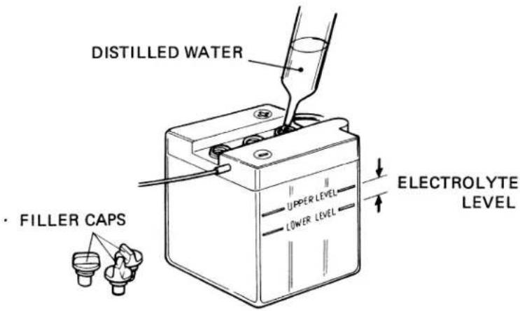
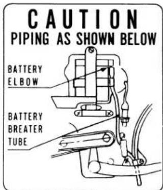

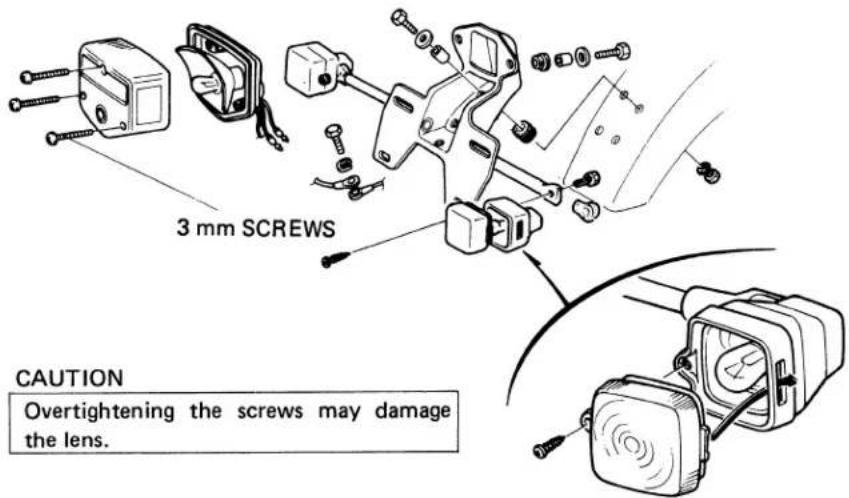
- WIRING DIAGRAM
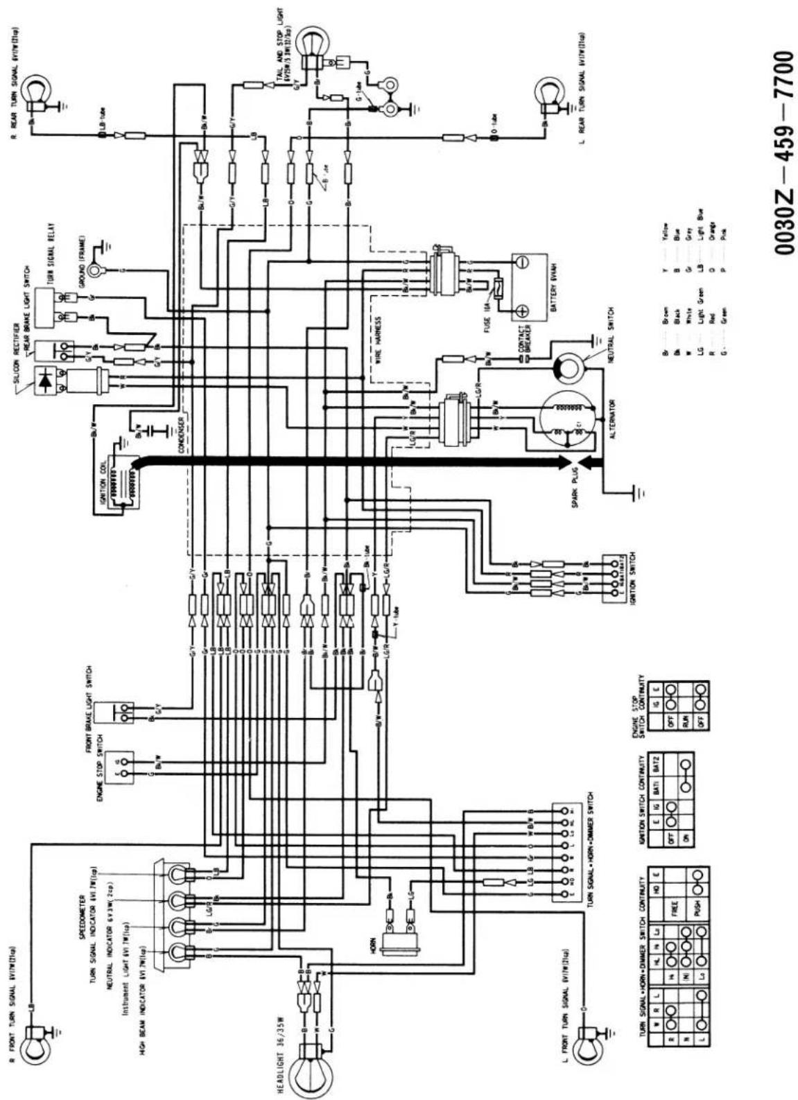
MEMO
INTRODUCTION
This Shop Manual Addendum contains information for the 1982 CT110. Refer to the base shop manual and the previous addendums for procedures and service data not included in this addendum.
ALL INFORMATION, ILLUSTRATIONS, DIRECTIONS AND SPECIFICATIONS INCLUDED IN THIS PUBLICATION ARE BASED ON THE LATEST PRODUCT INFORMATION AVAILABLE AT THE TIME OF APPROVAL FOR PRINTING. HONDA MOTOR CO., LTD. RESERVES THE RIGHT TO MAKE CHANGES AT ANY TIME WITHOUT NOTICE AND WITHOUT INCURRING ANY OBLIGATION WHATEVER.
NO PART OF THIS PUBLICATION MAY BE REPRODUCED WITHOUT WRITTEN PERMISSION.
HONDA MOTOR CO., LTD.
Service Publications Office
CONTENTS
I. SPECIFICATIONS ..... 186
II. SERVICE INFORMATION....187
III. INSPECTION/ADJUSTMENT....192
IV. CARBURETOR 192
V. IGNITION SYSTEM 194
VI. WIRING DIAGRAM....198
1. SPECIFICATIONS
This addendum lists only specifications which are new for 1982. Refer to the base shop manual and to previous addendums for information not covered here.
| FRAMECaster Angle | 68° | |
| ELECTRICALIgnitionA.C. GeneratorSpark Plug | CDI6V, 102W/5,000 rpm | |
| Standard | DR8ES-L (NGK) or X24ESR-U (ND) | |
| For cold climate,below 5°C (41°F) | DR7ES (NGK) or X22ESR-U (ND) | |
| For extendedhigh speed riding | DR8ES (NGK) or X27ESR-U (ND) | |
2. SERVICE INFORMATION
TROUBLESHOOTING
ENGINE DOES NOT START OR IS HARD TO START
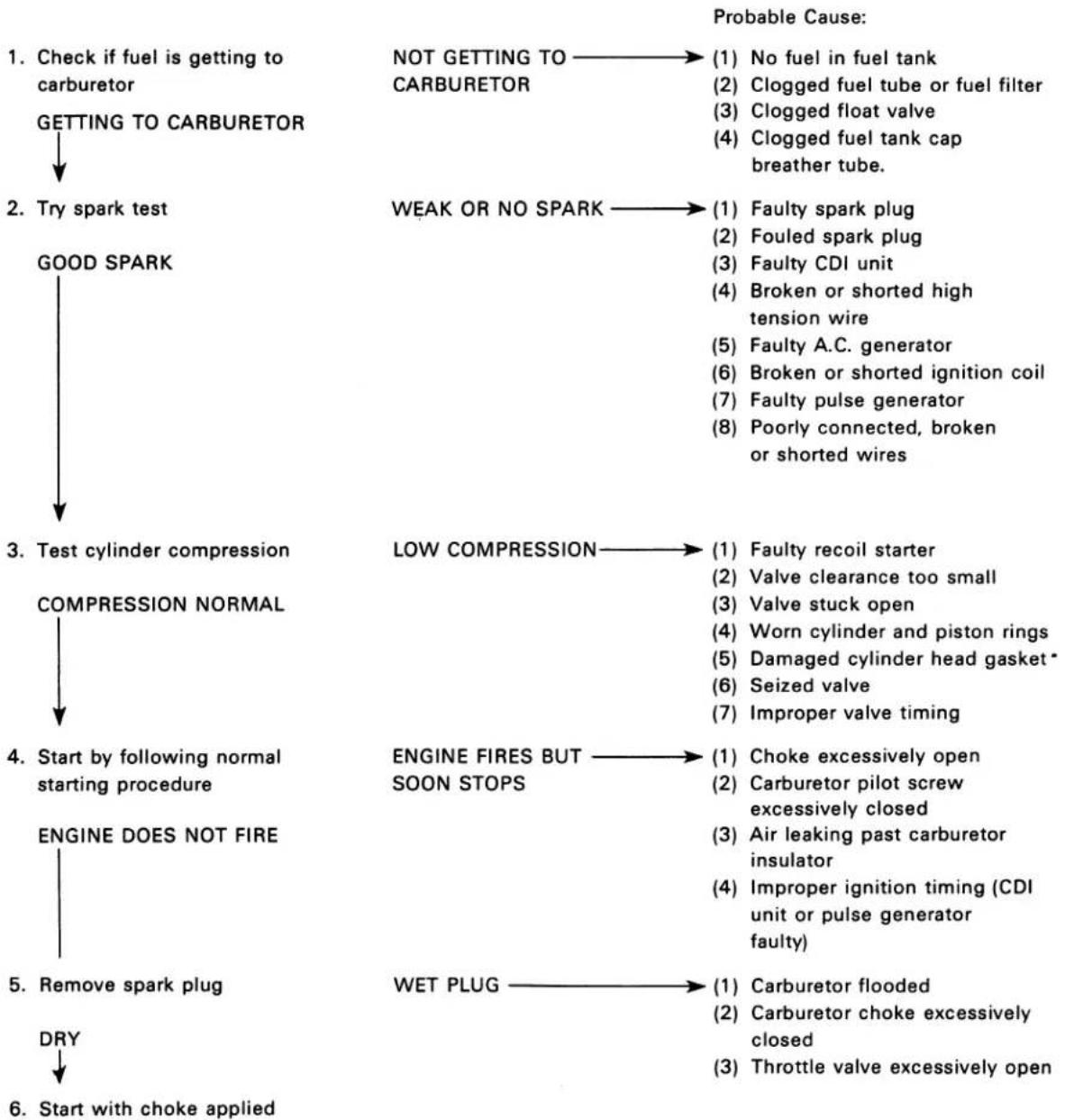
flowchart
graph TD
    A["1. Check if fuel is getting to carburetor"] --> B["GETTING TO CARBURETOR"]
    B --> C["2. Try spark test"]
    C --> D["GOOD SPARK"]
    D --> E["3. Test cylinder compression"]
    E --> F["COMPRESSION NORMAL"]
    F --> G["4. Start by following normal starting procedure"]
    G --> H["ENGINE DOES NOT FIRE"]
    H --> I["5. Remove spark plug"]
    I --> J["DRY"]
    J --> K["6. Start with choke applied"]

    L["NOT GETTING TO CARBURETOR"] --> M["(1) No fuel in fuel tank"]
    L --> N["(2) Clogged fuel tube or fuel filter"]
    L --> O["(3) Clogged float valve"]
    L --> P["(4) Clogged fuel tank cap breather tube"]

    Q["WEAK OR NO SPARK"] --> R["(1) Faulty spark plug"]
    Q --> S["(2) Fouled spark plug"]
    Q --> T["(3) Faulty CDI unit"]
    Q --> U["(4) Broken or shorted high tension wire"]
    Q --> V["(5) Faulty A.C. generator"]
    Q --> W["(6) Broken or shorted ignition coil"]
    Q --> X["(7) Faulty pulse generator"]
    Q --> Y["(8) Poorly connected, broken or shorted wires"]

    Z["LOW COMPRESSION"] --> AA["(1) Faulty recoil starter"]
    Z --> AB["(2) Valve clearance too small"]
    Z --> AC["(3) Valve stuck open"]
    Z --> AD["(4) Worn cylinder and piston rings"]
    Z --> AE["(5) Damaged cylinder head gasket*"]
    Z --> AF["(6) Seized valve"]
    Z --> AG["(7) Improper valve timing"]

    AH["ENGINE FIRES BUT SOON STOPS"] --> AI["(1) Choke excessively open"]
    AH --> AJ["(2) Carburetor pilot screw excessively closed"]
    AH --> AK["(3) Air leaking past carburetor insulator"]
    AH --> AL["(4) Improper ignition timing (CDI unit or pulse generator faulty)"]

    AM["WET PLUG"] --> AN["(1) Carburetor flooded"]
    AM --> AO["(2) Carburetor choke excessively closed"]
    AM --> AP["(3) Throttle valve excessively open"]
ENGINE LACKS POWER
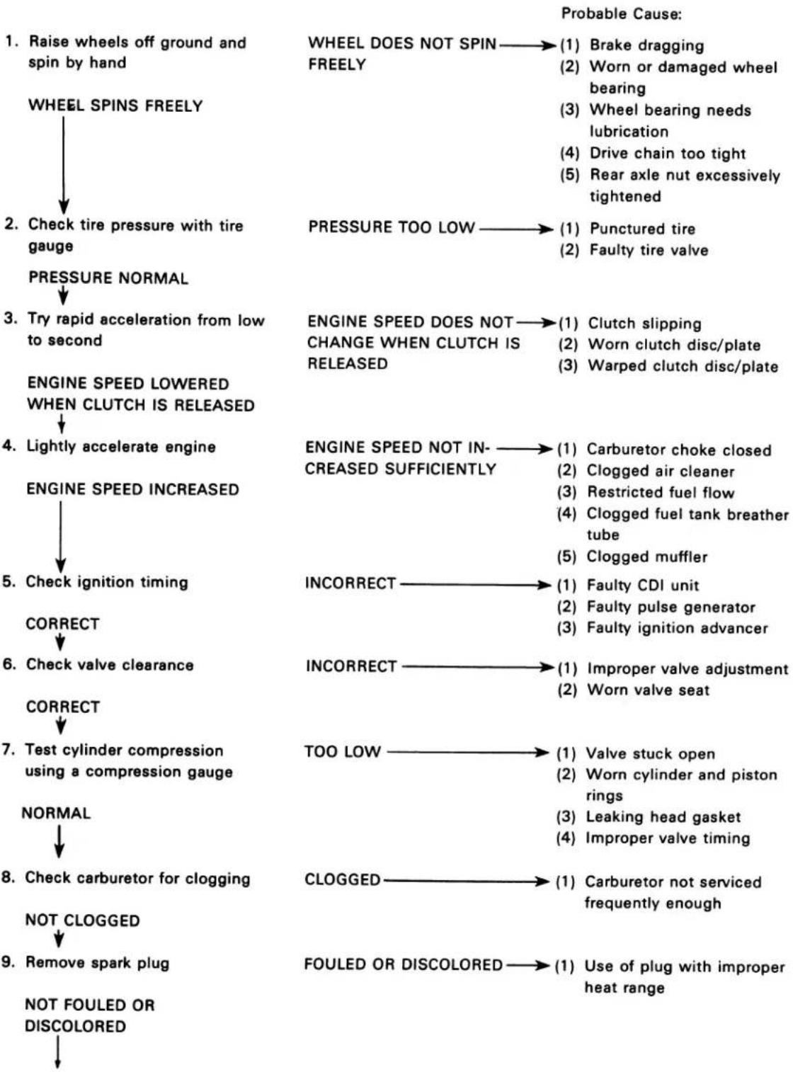
flowchart
graph TD
    A["1. Raise wheels off ground and spin by hand"] --> B["WHEEL SPINS FREELY"]
    B --> C["2. Check tire pressure with tire gauge"]
    C --> D["PRESSURE NORMAL"]
    D --> E["3. Try rapid acceleration from low to second"]
    E --> F["ENGINE SPEED LOWERED WHEN CLUTCH IS RELEASED"]
    F --> G["4. Lightly accelerate engine"]
    G --> H["ENGINE SPEED INCREASED"]
    H --> I["5. Check ignition timing"]
    I --> J["CORRECT"]
    J --> K["6. Check valve clearance"]
    K --> L["CORRECT"]
    L --> M["7. Test cylinder compression using a compression gauge"]
    M --> N["NORMAL"]
    N --> O["8. Check carburetor for clogging"]
    O --> P["NOT CLOGGED"]
    P --> Q["9. Remove spark plug"]
    Q --> R["NOT FOULED OR DISCOLORED"]

    S["1. WHEEL DOES NOT SPIN FREELY"] --> T["(1) Brake dragging"]
    S --> U["(2) Worn or damaged wheel bearing"]
    S --> V["(3) Wheel bearing needs lubrication"]
    S --> W["(4) Drive chain too tight"]
    S --> X["(5) Rear axle nut excessively tightened"]

    Y["PRESSURE TOO LOW"] --> Z["(1) Punctured tire"]
    Y --> AA["(2) Faulty tire valve"]

    AB["ENGINE SPEED DOES NOT CHANGE WHEN CLUTCH IS RELEASED"] --> AC["(1) Clutch slipping"]
    AB --> AD["(2) Worn clutch disc/plate"]
    AB --> AE["(3) Warped clutch disc/plate"]

    AF["ENGINE SPEED NOT INCREASED SUFFICIENTLY"] --> AG["(1) Carburetor choke closed"]
    AF --> AH["(2) Clogged air cleaner"]
    AF --> AI["(3) Restricted fuel flow"]
    AF --> AJ["(4) Clogged fuel tank breather tube"]
    AF --> AK["(5) Clogged muffler"]

    AL["INCORRECT"] --> AM["(1) Faulty CDI unit"]
    AL --> AN["(2) Faulty pulse generator"]
    AL --> AO["(3) Faulty ignition advancer"]

    AP["INCORRECT"] --> AQ["(1) Improper valve adjustment"]
    AP --> AR["(2) Worn valve seat"]

    AS["TOO LOW"] --> AT["(1) Valve stuck open"]
    AS --> AU["(2) Worn cylinder and piston rings"]
    AS --> AV["(3) Leaking head gasket"]
    AS --> AW["(4) Improper valve timing"]

    AX["CLOGGED"] --> AY["(1) Carburetor not serviced frequently enough"]
    AX --> AZ["FOULED OR DISCOLORED"] --> BA["(1) Use of plug with improper heat range"]
- Remove oil level gauge and check oil level
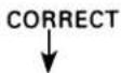
- Remove cylinder head cover and inspect lubrication
VALVE TRAIN LUBRICATED PROPERLY
- Check if engine overheats

- Accelerate or run at high speed ENGINE DOES NOT KNOCK
OIL LEVEL INCORRECT →(1) Oil level too high
(2) Oil level too low
(3) Contaminated oil
VALVE TRAIN NOT → (1) Clogged oil passage
LUBRICATED PROPERLY (2) Clogged oil control orifice
OVERHEATED → (1) Excessive carbon build-up in combustion chamber
(2) Use of improper quality of fuel
(3) Clutch slipping
(4) Fuel-air mixture too lean
ENGINE KNOCKS → (1) Worn piston and cylinder
(2) Fuel-air mixture too lean
(3) Use of improper grade of fuel
(4) Excessive carbon build-up in combustion chamber
(5) Ignition timing too advanced (Faulty CDI unit or spark advancer)
POOR PERFORMANCE AT LOW AND IDLE SPEEDS
- Check ignition timing and valve clearance

- Check carburetor pilot screw adjustment
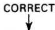
- Check if air is leaking past carburetor insulator

- Try spark test
GOOD SPARK
INCORRECT → (1) Improper valve clearance
(2) Improper ignition timing (Faulty CDI unit or spark advancer)
INCORRECT →(1) Fuel-air mixture too lean
(2) Fuel-air mixture too rich
LEAKING → (1) Deteriorated insulator O-ring
(2) Loose carburetor
WEAK OR INTERMITTENT → (1) Faulty, carbon or wet SPARK fouled spark plug
(2) Faulty CDI unit
(3) A.C. generator faulty
(4) Faulty ignition coil
(5) Faulty pulse generator
(6) Faulty spark advancer
POOR PERFORMANCE AT HIGH SPEEDS
flowchart
graph TD
    A["1. Check ignition timing and valve clearance"] --> B["2. Disconnect fuel tube at carburetor"]
    B --> C["3. Remove carburetor and check for clogged jet"]
    C --> D["4. Clean valve timing"]
    D --> E["5. Check valve spring tension NOT WEAKENED"]

    F["INCORRECT"] --> G["(1) Improper valve clearance"]
    F --> H["(2) Faulty CDI unit"]
    F --> I["(3) Faulty pulse generator"]
    F --> J["(4) Faulty spark advancer"]

    K["FUEL FLOW RESTRICTED"] --> L["(1) Lack of fuel in tank"]
    K --> M["(2) Clogged fuel line"]
    K --> N["(3) Clogged fuel tank breather tube"]
    K --> O["(4) Clogged fuel valve"]

    P["CLOGGED"] --> Q["(1) Clean"]

    R["INCORRECT"] --> S["(1) Cam sprocket not installed properly"]

    T["WEAK"] --> U["(1) Faulty spring"]
MAINTENANCE SCHEDULE
Perform the PRE-RIDE INSPECTION in the Owner's Manual at each scheduled maintenance period.
I: Inspect and Clean, Adjust, Lubricate or Replace, if necessary.
C: Clean
R: Replace
A: Adjust
L: Lubricate
| FREQUENCYITEM | WHICHEVER →COMESFIRST ↓ | ODOMETER READING (NOTE 4) | |||||
| 600mi.(1,000km) | 2,500mi.(4,000km) | 5,000mi.(8,000km) | 7,500mi.(12,000km) | Refer toPage | |||
| EVERY | |||||||
| EMISSION RELATED ITEMS | ·FUEL LINE | I | I | I | 118 | ||
| ·FUEL STRAINER | C | C | C | C | 193 | ||
| ·THROTTLE OPERATION | I | I | I | I | 122 | ||
| ·CARBURETOR-CHOKE | I | I | I | 122 | |||
| AIR CLEANER | NOTE 1 | C | C | C | 117 | ||
| CRANKCASE BREATHER (USA only) | NOTE 2 | C | C | C | 117 | ||
| SPARK PLUG | R | R | R | 151 | |||
| ·VALVE CLEARANCE | I | I | I | I | 152 | ||
| ENGINE OIL | YEAR | R | REPLACE EVERY1,250mi. (2,000km) | 151 | |||
| ·ENGINE OIL FILTER SCREEN | C | 116 | |||||
| ·CAM CHAIN TENSION | A | A | A | A | 121 | ||
| ·CARBURETOR-IDLE SPEED | I | I | I | I | 122 | ||
| NON-EMISSION RELATED ITEMS | DRIVE CHAIN | NOTE 3 | I, L EVERY 300mi. (500km) | 123 | |||
| BATTERY | MONTH | I | I | I | I | 154 | |
| BRAKE SHOE WEAR | I | I | I | 125 | |||
| BRAKE SYSTEM | I | I | I | I | 125 | ||
| ·BRAKE LIGHT SWITCH | I | I | I | I | 127 | ||
| ·HEADLIGHT AIM | I | I | I | I | 127 | ||
| CLUTCH | I | I | I | I | 128 | ||
| SIDE STAND | I | I | I | 128 | |||
| ·SUSPENSION | I | I | I | I | 128 | ||
| ·SPARK ARRESTER (USA only) | C | C | C | 129 | |||
| ·NUTS, BOLTS, FASTENERS | NOTE 3 | I | I | I | I | 130 | |
| ·WHEELS/SPOKES | NOTE 3 | I | I | I | I | 130 | |
| ·STEERING HEAD BEARING | I | I | 131 | ||||
* Should be serviced by an authorized HONDA dealer, unless the owner has proper tools and service data and is mechanically qualified.
** In the interest of safety, we recommend these items be serviced ONLY by an authorized HONDA dealer.
NOTES: 1. Service more frequently when riding in dusty areas.
- Service more frequently when riding in rain or at full throttle. (USA ONLY)
- Service more frequently when riding OFF-ROAD.
- For higher odometer readings, repeat at the frequency interval established here.
3. INSPECTION/ADJUSTMENT
ENGINE OIL RECOMMENDATION
Use HONDA 4-STROKE OIL or equivalent. API SERVICE CLASSIFICATION: SE or SF Viscosity: SAE 10W-40
Other viscosities may be used when the average temperature in your riding area is within the chart's indicated range.
FUEL STRAINER
Turn the fuel valve OFF.
Loosen the carburetor drain screw and drain the fuel from the carburetor into a suitable container.
WARNING
Gasoline is flammable and is explosive under certain conditions. Do not smoke or allow flames or sparks near the equipment while draining fuel.
Remove the fuel filter bolt and pull out the fuel filter and O-rings.
Wash the fuel filter in clean non-flammable or high flash point solvent.
Reinstall the fuel filter and new O-rings into the fuel valve. Then make sure the new O-rings are in place.
Hand tighten the fuel filter bolt, then torque to specification.
TORQUE: 3-5 N·m (0.3-0.5 kg·m, 2-4 ft·lb)
After installing, turn the fuel valve ON and check that there are no fuel leaks.
4. CARBURETOR
SLOW JET
Remove the carburetor (see pages 78-79).
Remove the float chamber body.
Remove the float arm pin.
Remove the float and float valve.
Remove the main jet, needle jet holder, needle jet and slow jet.
Blow out all jets and body openings with compressed air.
Inspect each part for wear and damage.
bar
RECOMMENDED OIL VISCOSITIES | Oil Type | Viscosity (°F) | | :--- | :--- | | SAE 20W-40, 20W-50 | 15 | | SAE 10W-40 | -5 | | SAE 10W-30 | 90 |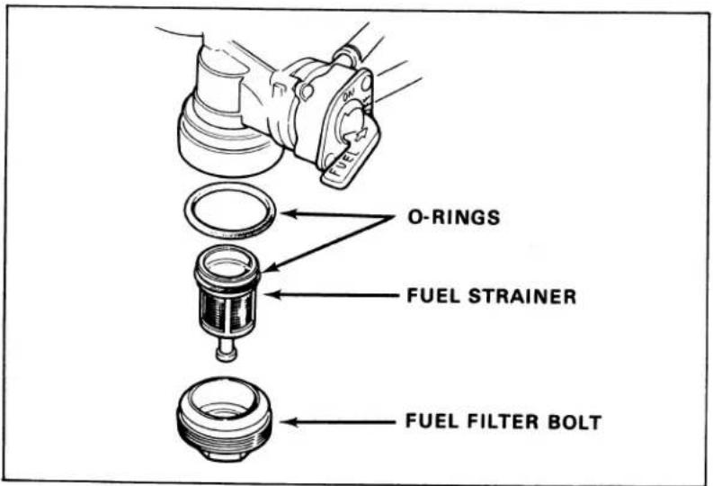
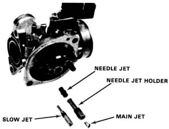
HIGH ALTITUDE ADJUSTMENT (U.S.A. only)
When the vehicle is to be operated continuously above 6,500 feet (2,000 m), the carburetor must be readjusted as described below to improve driveability and decrease exhaust emissions.
Remove the carburetor.
Remove the carburetor float chamber.
Remove the #72 main jet and install the #70 main jet.
MAIN JET SPECIFICATIONS
| Altitude | Main Jet |
| Above 6,500 feet (2,000 m) | #70 |
| Below 5,000 feet (1,500 m) | #72 |
Reassemble and install the carburetor.
Warm up the engine to operating temperature. Stop and go driving for 10 minutes is sufficient.
Adjust the idle speed to 1,500 ± 100 rpm with the throttle stop screw.
NOTE
This adjustment must be made at high altitude to ensure proper high altitude operation.
Attach the Vehicle Emission Control Information Update label as shown.
NOTE
- Instructions for obtaining Vehicle Emission Control Information Update labels are given in Service Newsletter No. 132.
- Do not attach the label to any part that can be easily removed from the vehicle.
CAUTION
Continuous operation at an altitude lower than 5,000 feet (1,500 m) with the carburetor adjusted for high altitudes may cause the engine to idle roughly and stall and could cause engine damage from overheating.
When the vehicle is to be operated continuously below 5,000 feet (1,500 m), reinstall the #72 main jet and adjust the idle speed to 1,500 ± 100 rpm. Be sure to do these adjustments at low altitude.
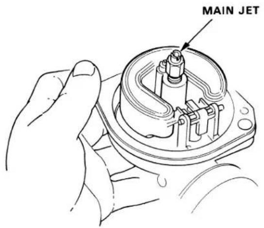
VEHICLE EMISSION CONTROL UPDATE LABEL

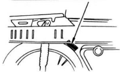
natural_image
Line drawing of a car front view showing steering wheel and dashboard (no text or symbols)5. IGNITION SYSTEM
Ignition timing does not normally need to be adjusted since the CDI (Capacitive Discharge Ignition) is factory pre-set.
| Item | Specification | |
| Spark plug | Standard | DR8ES-L (NGK) or X24ESR-U (ND) |
| For cold climate below 5°C (41°F) | DR7ES (NGK) or X22ESR-U (ND) | |
| For extended high speed riding | DR8ES (NGK) or X27ESR-U (ND) | |
| Spark plug gapIgnition timingInitialAdvance startsFull advanceA.C. generator | 0.6-0.7 mm (0.0024-0.0028 in)10 ± 2° BTDC at 1,500 rpm (F mark)1,950 ± 150 rpm32 ± 2° BTDC at 3,400 rpm102 W at 5,000 rpm | |
IGNITION
TROUBLESHOOTING
The probable causes listed below cover ignition-related trouble only. Refer to Troubleshooting, page 187, and qualify other factors that affect performance (fuel delivery, compression, etc.).
Engine starts hard or not at all
- No spark at plug
- Improper ignition timing
- Faulty spark plug
No spark at plug
- Engine stop switch "OFF"
- Poorly connected, broken or shorted wires
— Between A.C. generator and ignition coil
— Between CDI unit and engine stop switch
— Between CDI unit and ignition coil
— Between ignition coil and spark plug
— Between pulse generator and CDI unit
- Faulty ignition coil
- Faulty CDI unit
- Faulty pulse generator
- Faulty A.C. generator
Engine starts but runs poorly
- Ignition primary circuit
— Faulty ignition coil
— Loose or bare wire
— Faulty A.C. generator
- Ignition secondary circuit
— Faulty plug
— Faulty CDI unit
— Faulty pulse generator
— Faulty high tension wire
- Improper ignition timing
— Faulty advancer rotor
— Faulty pulse generator
— Faulty CDI unit
IGNITION COIL
REMOVAL
Remove the exhaust pipe.
Remove the fuel tank (page 96).
Remove the spark plug cap from the spark plug.
Remove the two bolts holding the ignition coil.
Disconnect the ignition coil wire.
Remove the ignition coil.
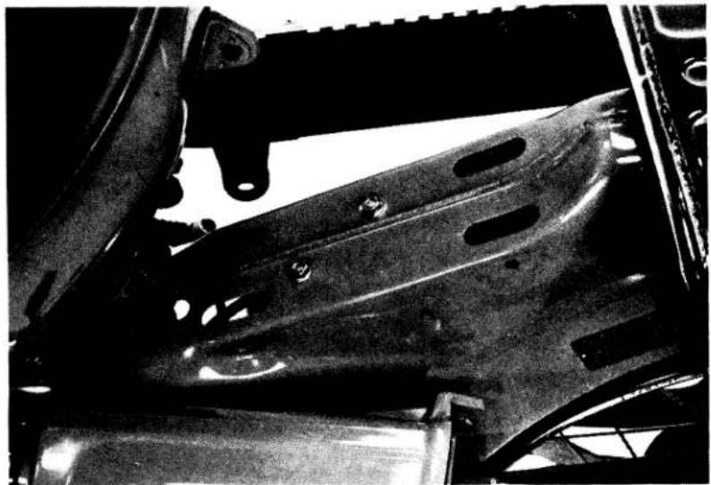
natural_image
Close-up of a car's undercarriage frame with visible bolts and structural components (no text or symbols)INSPECTION
Check the resistance of the primary and secondary coils.
PRIMARY COIL: 0.2 - 0.8 Ω
SECONDARY COIL: 8 - 15K Ω
If either resistance is not within its specified range, replace the coil.
INSTALLATION
Install the ignition coil in the reverse order of removal.
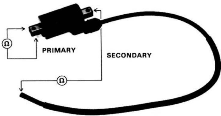
A.C. GENERATOR
Disconnect the A. C. generator wire coupler and test as follows:
NOTE
It is not necessary to remove the stator coil to make this test.
Check the resistance for the wires listed.
Yellow and ground: 0.3 — 0.6 Ω
Black/red and ground: 290 — 520 Ω
Pink and white/yellow: 0.3 — 0.6 Ω
If one or more resistance is not within the ranges given, replace the stator (page 160).
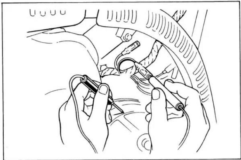
natural_image
Line drawing of hands using a tool to adjust or install a car wheel (no text or symbols visible)CDI UNIT
Remove the right side cover, and battery case.
Disconnect the CDI wire coupler.
Remove the CDI unit.
CDI UNIT INSPECTION
Replace the CDI unit if any of the readings are not within the limits shown in the table.
Check resistances between the leads with either a SANWA (P/N 7308-002-0000) or KOWA (TH-5H) electrical tester.
Make sure the tester is equipped with serviceable batteries.
Select the correct range and perform zero adjustment before testing to ensure accurate readings.
SANWA: xK
KOWA: x100
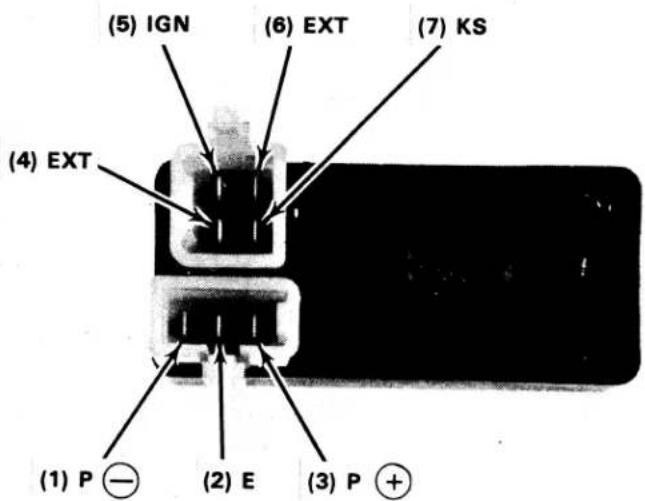
| (一) (+) | (7) | (6) | (4) | (2) | (3) | (1) | (5) |
| (7) | |||||||
| (6) | 5-100 | ||||||
| (4) | |||||||
| (2) | 1-50 | 0 | |||||
| (3) | 2-60 | 2-60 | 2-60 | ||||
| (1) | 1-50 | 0 | |||||
| (5) |
PULSE GENERATOR RESISTANCE
Disconnect the pulse generator wires.
Measure the resistance between the blue/yellow and green wires.
RESISTANCE: 90-110 Ω
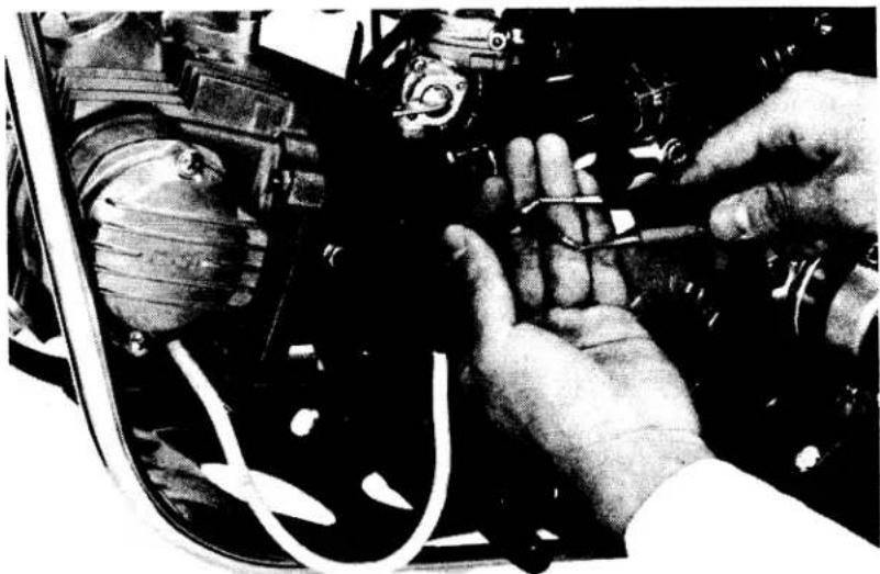
natural_image
Close-up of hands working on an automotive engine component with visible wiring and valve (no text or symbols)IGNITION TIMING
Remove the timing hole cap.
Connect a timing light.
Start the engine and allow it to idle.
IDLE (1,500 rpm): F mark should be aligned with index mark.
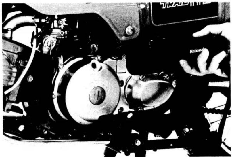
natural_image
Close-up of a mechanical assembly with visible gears and components, no readable text or symbols