Z50R (1985) - Motorrad Honda - Kostenlose Bedienungsanleitung
Finden Sie kostenlos die Bedienungsanleitung des Geräts Z50R (1985) Honda als PDF.

Benutzerfragen zu Z50R (1985) Honda
0 Frage zu diesem Gerät. Beantworten Sie die, die Sie kennen, oder stellen Sie Ihre eigene.
Eine neue Frage zu diesem Gerät stellen
Laden Sie die Anleitung für Ihr Motorrad kostenlos im PDF-Format! Finden Sie Ihr Handbuch Z50R (1985) - Honda und nehmen Sie Ihr elektronisches Gerät wieder in die Hand. Auf dieser Seite sind alle Dokumente veröffentlicht, die für die Verwendung Ihres Geräts notwendig sind. Z50R (1985) von der Marke Honda.
BEDIENUNGSANLEITUNG Z50R (1985) Honda
Z50R
1985 HONDA
OWNER'S MANUAL
IMPORTANT NOTICE
- OPERATOR ONLY. NO PASSENGER.
This motorcycle is designed and constructed as an operator only model. The seating configuration does not safely permit the carrying of a passenger. Do not exceed the vehicle capacity load as shown on the tire information label.
- FOR OFF-ROAD USE ONLY.
This motorcycle is designed and manufactured for off-road use only. Obey local laws and regulations.
- READ OWNER'S MANUAL CAREFULLY.
- NOT RECOMMENDED FOR CHILDREN UNDER 7 YEARS OLD.
Pay special attention to statements preceded by the following words.
WARNING
Indicates a strong possibility of severe personal injury or loss of life if instructions are not followed.
CAUTION:
Indicates a possibility of personal injury or equipment damage if instructions are not followed.
NOTE:
Gives helpful information.
This manual should be considered a permanent part of the motorcycle and should remain with the motorcycle when resold.
IONDA Z50R OWNER'S MANUAL
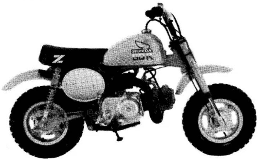
natural_image
Side view of a Honda motorcycle with visible wheels and engine components (no text or symbols)All information in this publication is based on the latest product information available at the time of approval for printing. HONDA MOTOR CO., LTD. reserves the right to make changes at any time without notice and without incurring any obligation. No part of this publication may be reproduced without written permission.
© Honda Motor Co., Ltd. 1984
WELCOME,
The motorcycle presents you a challenge to master the machine, a challenge to adventure. You can ride over many types of terrain on a vehicle that responds to your commands as no other does. Unlike an automobile, there is no metal cage around you. Like an airplane, a pre-ride inspection and regular maintenance are essential to your safety. Your reward is freedom.
To meet the challenges safely, and to enjoy the adventure fully, you should become thoroughly familiar with this owner's manual BEFORE YOU RIDE THE MOTOR-CYCLE.
When service is required, remember that your Honda dealer knows your motorcycle best. If you have the required mechanical "know-how" and tools, your dealer can supply you with an official Honda Shop Manual to help you perform many maintenance and repair tasks.
Pleasant riding, and thank you for choosing a Honda!
CONTENTS
MOTORCYCLE SAFETY ...... 1
Message To Parents 2
Protective Apparel 4
Modifications 4
Loading and Accessories 5
DESCRIPTION 6
Parts Location 6
Serial Numbers 9
Color label 10
Parts Function 10
Fuel 11
Engine Oil 13
Tires 15
OPERATION 17
Pre-ride Inspection 17
Starting the Engine 18
Break-in 20
Riding 20
Braking 22
Parking 22
Tool Kit 23
MAINTENANCE 24
Maintenance Schedule 25
Engine Oil 27
Spark Plug 28
Contact Breaker Point Gap and Ignition Timing 29
Valve Clearance 30
Cam Chain 32
Air Cleaner 3
Spark Arrester 34
Throttle Cable 3:
Carburetor 30
Fuel Filter 3
Clutch 3
Drive Chain 31
Front Brake 4
Rear Brake 4
Front Suspension 4:
Rear Suspension 40
Side Stand 4
Front Wheel Removal 4'
Rear Wheel Removal 41
CLEANING 4
STORAGE GUIDE 50
NOISE EMISSION CONTROL SYSTEM (USA ONLY).... 52
SPECIFICATIONS 53
MOTORCYCLE SAFETY
Read these WARNING LABELS before you ride!
MESSAGE TO PARENTS
This motorcycle is designed for junior riders (rider weight of 150 pounds or less). It is a fine learning motorcycle as long as the following precautions are observed:
* The parent or instructor must be fully familiar with the motorcycle, the motorcycle controls, and the control functions before starting to teach a junior rider. Both instructor and student must fully understand everything in this manual before riding instruction begins.
* The Z50R is an OPERATOR ONLY model. The rider weight limit of 150 pounds must be observed.
* The student rider must be of sufficient size to hold the motorcycle up while straddling it with both feet on the ground. The rider must also have
sufficient strength to pick up the motorcycle if it is on its side.
* The practice location must be a level, uncongested off-road area free of obstacles.
* It is illegal to ride the Z50R on public streets, roads or highways. It must be ridden only in off-road areas where such activities are permitted. If it becomes necessary to cross a public roadway, remember to get off the Z50R and push it across.
* For safety, the Z50R must be properly maintained. Be sure to make a “Pre-ride Inspection” before riding and be sure to impress the student rider with the importance of checking all the items thoroughly before riding the motorcycle.
* A prime objective in the instruction process is developing the student's self-confidence. This self-confidence comes with a total familiarization with the motorcycle controls and their functions, plus lots of PRACTICE.
* Always obey local off-road riding laws and regulations.
* Obtain permission to ride on private property. Avoid posted areas and obey "no trespassing" signs.
* When basic riding techniques have been mastered by the young rider remember these next few words of caution: The young rider should always ride in the company of an adult on another motorcycle so they can assist each other in the event of trouble.
* Familiarity with the motorcycle is critically important should a problem occur far from help.
* Caution the young rider never to ride beyond his ability and experience or faster than conditions warrant.
* If you are not familiar with the terrain lead the way and ride cautiously. Hidden rocks, holes or ravines could spell trouble.
PROTECTIVE APPAREL
-
Most motorcycle accident fatalities are due to head injuries: ALWAYS wear a helmet. You should also wear a face shield or goggles, boots, gloves, and protective clothing.
-
The exhaust system becomes very hot during operation, and it remains hot after operation. Never touch any part of the hot exhaust system. Wear clothing that fully covers your legs.
-
Do not wear loose clothing which could catch on the control levers, kickstarter, footpegs, drive chain, or wheels.
MODIFICATIONS
WARNING
* Modification of the motorcycle, or removal of original equipment, may render the vehicle unsafe or illegal. Obey all federal, state, and local equipment regulations.
* Spark arresters and mufflers are required in most 'areas. Don't modify your exhaust system.
* Remember that excessive noise bothers everyone and creates a bad image for motorcycling.
LOADING AND ACCESSORIES
WARNING
* A motorcycle is sensitive to changes in weight distribution. Improper loading of cargo and mounting of accessories can impair the motorcycle's stability and performance. To prevent an accident, use extreme care when mounting accessories and riding with cargo.
These general guidelines may help you decide whether or how to equip your motorcycle:
The vehicle capacity load is 150 lbs. The combined weight of the rider and cargo must not exceed this limit.
-
Keep cargo and accessory weight low and close to the center of the motorcycle. Load weight equally on both sides to minimize imbalance. As weight is located farther from the motorcycle's center of gravity, handling is proportionally affected.
-
All cargo and accessories must be secure for stable handling. Recheck security frequently.
-
Do not attach large or heavy items to the handlebars, front forks, or fender. Unstable handling or slow steering response may result.
DESCRIPTION
PARTS LOCATION
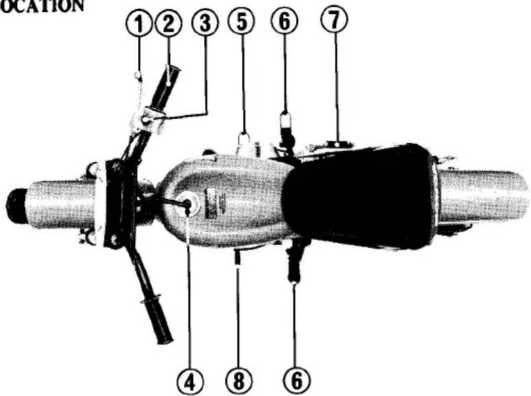
(1) Front brake lever
(2) Throttle grip
(3) Engine stop switch
(4) Fuel tank cap
(5) Rear brake pedal
(6) Footpeg
(7) Kickstarter
(8) Gearshift pedal
(1) Choke lever
(2) Gearshift pedal
(3) Fuel valve
(1) Kickstarter
(2) Oil filler cap
(3) Rear brake pedal
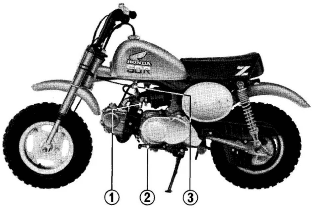
SERIAL NUMBERS
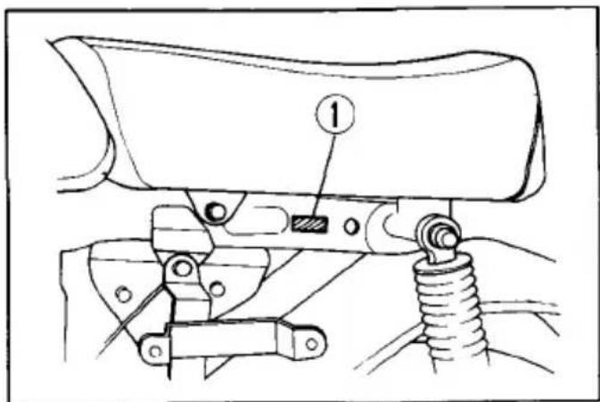
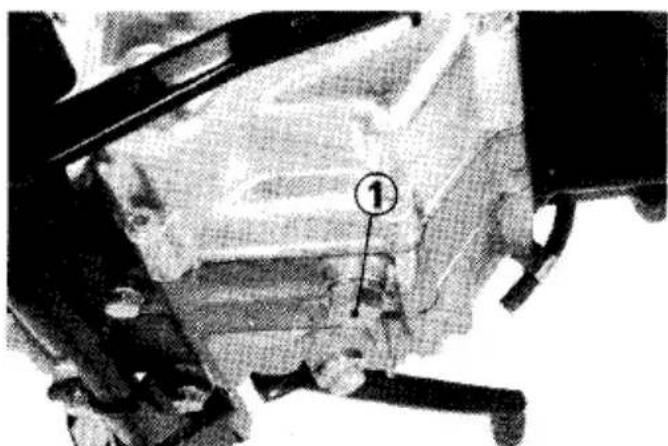
The frame and engine serial numbers are required when registering your motorcycle. They may also be required by your dealer when ordering replacement parts. The frame serial number (1) is stamped on the left of the steering head.
The engine serial number (2) is located on the left side of the engine. Record the numbers here for your reference.
FRAME NO. ____
natural_image
Close-up of a person using a mechanical device with no visible text or symbols(1) Frame serial number
ENGINE NO. ____
(2) Engine serial number
COLOR LABEL
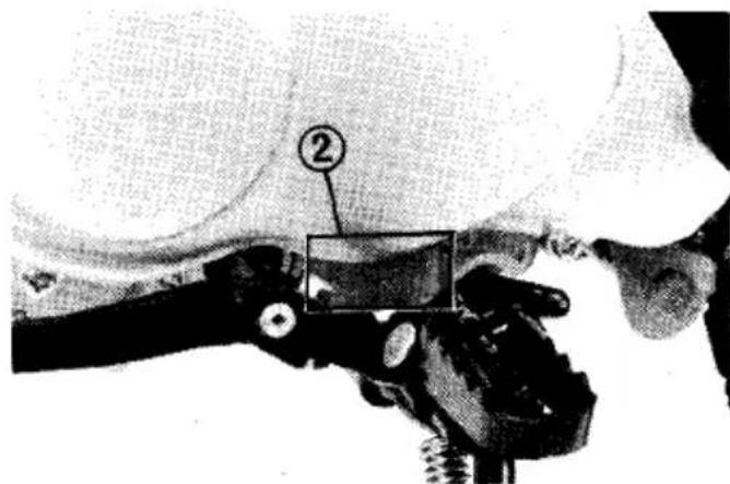
The color label (1) is attached to the frame below the seat. It is helpful when ordering replacement parts. Record the color and code here for your reference.
COLOR
CODE
(1) Color label
PARTS FUNCTION
Engine Stop Switch
The three-position engine stop switch (1) is next to the throttle grip. When the switch is in the RUN position, the engine will operate. When the switch is in either OFF position the engine will not operate.
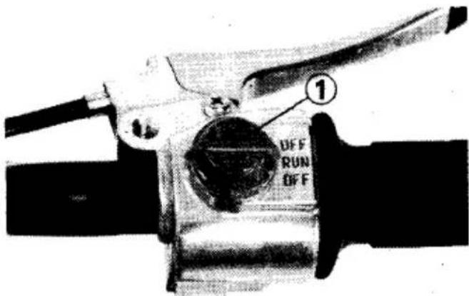
(1) Engine stop switch
FUEL
Fuel Valve
The three way fuel valve (1) is under the left side of the fuel tank.
OFF
With the fuel valve in the OFF position, fuel cannot flow from the tank to the carburetor. Turn the valve off whenever the motorcycle is not in use.
ON
With the fuel valve in the ON position, fuel will flow from the main fuel supply to the carburetor.
RES
With the fuel valve in the RES position, fuel will flow from the reserve fuel supply to the carburetor. Use the reserve fuel only when the main supply is gone. Refill the tank as soon as possible after switching to RES. The reserve fuel supply is 0.7l (0.18 U S gal)
WARNING
* Be careful not to touch any hot engine parts while operating the fuel valve.
NOTE:
* Do not operate the motorcycle with the fuel valve in the RES position after refueling. You may run out of fuel with no reserve.
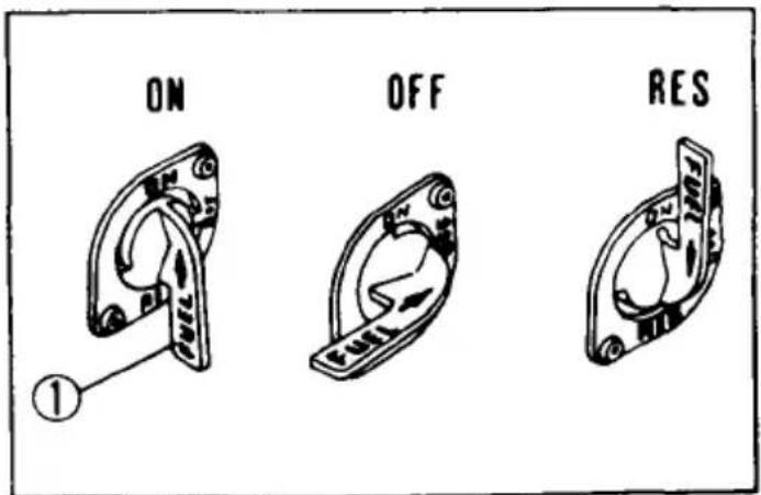
(1) Fuel valve
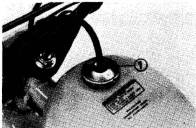
Fuel Tank
Fuel tank capacity is 5.0 ℓ (1.3 US gal) including 0.7 ℓ (0.18 US gal) in the reserve supply. The fuel tank cap (1) is removed by twisting it counterclockwise. Any automotive gasoline with a pump octane number ( + M2 ) of 86 or higher, or a research octane number of 91 or higher may be used.
If "knocking" or "pinging" occurs, try a different brand of gasoline or a higher octane grade. Also, check the ignition
natural_image
Close-up of a vintage office lamp with a metallic stand and a small label (no visible text or symbols)(1) Fuel tank cap
timing if knocking or pinging continues. After refueling, be sure to tighten the fuel tank cap firmly.

WARNING
* Gasoline is extremely flammable and is explosive under certain conditions. Refuel in a well ventilated area with engine stopped. Do not smoke or allow open flames or sparks in the area where the motorcycle is refueled or where gasoline is stored.
* Do not overfill the tank. After refueling, make sure the tank cap is closed securely.
ENGINE OIL
Engine Oil Level Check
Check the engine oil level each day before operating the motorcycle.
The oil filler cap (1) is on the right crank-case cover and contains a dipstick for measuring oil level. The oil level must be maintained between the upper (2) and lower (3) level marks on the dipstick.
- With the motorcycle standing upright on level ground, remove the oil filler cap/dipstick and wipe it clean.
- Reinsert the dipstick without screwing it in and check the oil level. The oil should be between the upper (2) and lower (3) level marks on the dipstick.
- If required, add the specified oil up to the upper level mark. Do not overfill.
- Replace the filler cap/dipstick. Check for oil leaks.
CAUTION:
* Running the engine with insufficient oil can cause serious engine damage.
(1) Oil filler cap/dipstick (3) Lower level mark
(2) Upper level mark
Engine Oil Recommendation
USE HONDA 4-STROKE OIL OR AN EQUIVALENT.
Use only high detergent, premium quality motor oil certified to meet or exceed US automobile manufacturers' requirements for Service Classification SE or SF.
Motor oils intended for Service SE or SF will show this designation on the container. The use of special oil additives is unnecessary and will only increase operating expenses.
CAUTION:
* Engine oil is a major factor affecting the performance and service life of the engine. Non-detergent, vegetable, or castor based racing oils are not recommended.
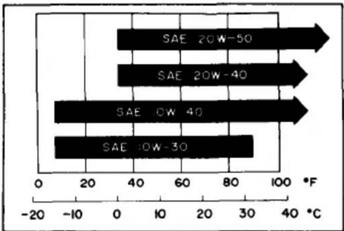
Recommended Oil Viscosity
SAE 10W-40
Other viscosities shown in the chart below may be used when the average temperature in your riding area is within the indicated range.
bar
| Category | Value (°F) | |---|---| | SAE 20W-50 | 100 | | SAE 20W-40 | 80 | | SAE OW 40 | 60 | | SAE 30W-30 | 40 |IRES
roper air pressure will provide maximum ability, riding comfort and tire life. heck tire pressures frequently and adjust necessary.
OTE:
Tire pressure should be checked when the tires are "cold," before you ride.
'heck the tires for cuts, imbedded nails, r other sharp objects.
IOTE:
Off-road tires are standard on this model. Select the right replacement tires in accordance with the following specifications:
| Cold tire pressures psi (kPa, kg/cm2) | Front: 14 (100, 1.0) |
| Rear: 14 (100, 1.0) | |
| Vehicle capacity load | 68 Kg (150 lbs) |
| Tire size | Front: 3.50-8-2PR |
| Rear: 3.50-8-2PR |

WARNING
* Improper tire inflation will cause abnormal tread wear and create a safety hazard. Underinflation may result in the tire slipping on, or coming off of the rim.
* Operation with excessively worn tires is hazardous and will adversely affect traction and handling.
* Replace tires before tread depth at the center of the tires reaches the following limit:
| Minimum tread depth |
| 3 mm (1/8 in) |
OPERATION
PRE-RIDE INSPECTION
WARNING
* If the Pre-ride Inspection is not performed, serious damage or an accident may result.
Inspect your motorcycle every day before you ride it. The items listed here will only take a few minutes to check and, in the long run, can save time, expense and possibly your life.
-
Engine oil level—If required, add engine oil (page 13). Check for leaks.
-
Fuel level-fill the fuel tank when necessary (page12). Check for leaks.
-
Front and rear brakes—check operation. If necessary adjust free play (pages 42—45).
-
Tires-check condition and pressure (page 15).
-
Drive chain-check condition and slack (pages 38—42). Adjust and lubricate if necessary.
-
Throttle-check for smooth opening and closing in all steering positions, Adjust free play if necessary (page 35).
-
Engine stop switch—check for proper function (page 10).
Correct any discrepancy before you ride. Contact your authorized Honda dealer for assistance if you cannot correct the problem.
STARTING THE ENGINE
WARNING
* Never run the engine in a closed area. The exhaust contains poisonous carbon monoxide gas.
* Do not try to start the motorcycle with the transmission in gear. You may injure yourself or damage the motorcycle.
PREPARATION
Make sure the transmission is in neutral, and the engine stop switch is at RUN.
Turn the fuel valve to ON.
STARTING PROCEDURE
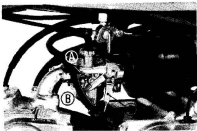
Cold Engine
-
Raise the choke lever to Fully Closed (A).
-
Open the throttle slightly and operate the kickstarter with the right foot, starting from the top of the stroke and following through to the bottom with a rapid and continuous kick.
CAUTION:
* Do not allow the kickstarter to snap back against the pedal stop. Engine case damage may result.
natural_image
Black-and-white photo of a mechanical assembly with labeled parts A and B, no readable text or symbols present.(1) Choke lever
Ⓐ Fully Closed
⑧ Detent position
© Fully Open
- Immediately after the engine starts, push the choke lever down to the Detent position (B).
- About a half minute after the engine starts, push the choke lever down all the way to Fully Open (C).
- If idling is unstable, open the throttle slightly.
Warm Engine
When the engine is to be re-started while still warm, follow the "Cold Engine" Starting Procedure; however, do not use the choke.
Starting in Extremely Cold Weather
Prime the engine before starting by cranking the engine several times with the kickstarter. The engine stop switch should be OFF, the choke Fully Closed (A) and the throttle opened slightly. Follow the "Cold Engine" Starting Procedure.
CAUTION:
* Extended use of the choke may impair piston and cylinder wall lubrication.
Flooded Engine
If the engine fails to start after several repeated attempts, it may have become flooded with excess fuel. To clear the engine, turn off the engine stop switch and lower the choke lever to Fully Open (C). Open the throttle fully and crank the engine several times with the kickstarter.
Turn the engine stop switch to RUN and open the throttle slightly; start the engine using the kickstarter.
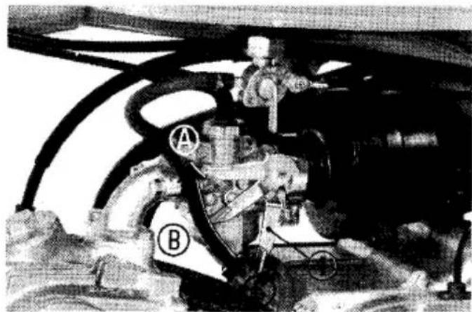
natural_image
Black-and-white photo of a mechanical assembly with labeled components (A and B), no visible text or symbols.(1) Choke lever
Ⓐ Fully Closed
⑧ Detent position
© Fully Open
BREAK-IN
During the first week of operation, operate your new Z50R so the engine neither pulls laboriously nor approaches maximum speed in any gear. Avoid full throttle operation, and select your gear changes to spare the engine undue stress. Careful break-in operation during the initial mileage will measurably extend the service life of the engine.
RIDING
WARNING
* Review Motorcycle Safety (pages 1—5) before you ride.
* Make sure the side stand is fully retracted before riding the motorcycle. If the stand is extended, it may interfere with control during a left turn.
1. After the engine has warmed up, the motorcycle is ready for riding.
2. Close the throttle and depress the gearshift pedal to shift into 1st (low) gear.
3. Increase engine speed by gradually opening the throttle.
- When your speed increases, close the throttle and shift to 2nd gear by depressing the gearshift pedal.
CAUTION:
* Do not shift gears without closing the throttle. The engine and drive train could be damaged by overspeed and shock.
Shifting pattern
- This sequence is repeated to shift to 3rd gear.
Depress the pedal to shift to a higher gear and raise the pedal to shift to a lower gear. Each stroke of the pedal engages the next gear in sequence. The pedal automatically returns to the horizontal position when released.
WARNING
* Do not downshift when traveling at a speed that would force the engine to overrev in the next lower gear, or cause the rear wheel to lose traction.
CAUTION:
* Do not tow the motorcycle or coast for long distances while the engine is off. The transmission will not be properly lubricated and damage may result.
BRAKING
- For normal braking, gradually apply both front and rear brakes while down-shifting to suit your road speed.
- For maximum deceleration, close the throttle and apply the front and rear brakes firmly.
WARNING
* Independent use of only the front or rear brake reduces stopping performance. Extreme braking may cause either wheel to lock, reducing control of the motorcycle.
* When possible reduce speed or brake before entering a turn; closing the throttle or braking in mid-turn may cause wheel slip. Wheel slip will reduce control of the motorcycle.
* When riding in wet or rainy conditions, or on loose surfaces, the ability to maneuver and stop will be reduced. All of your actions should be smooth
under these conditions. Sudden acceleration, braking or turning may cause loss of control. For your safety, exercise extreme caution when braking, accelerating or turning.
* When descending a long, steep grade, use engine compression braking by downshifting, with intermittent use of both brakes. Continuous brake application can overheat the brakes and reduce their effectiveness.
PARKING
- After stopping the motorcycle, shift the transmission into neutral, turn the fuel valve OFF, and turn the ignition switch OFF
- Use the side stand to support the motorcycle while parked.
CAUTION:
* Park the motorcycle on firm, level ground to prevent overturning.
Tool Kit
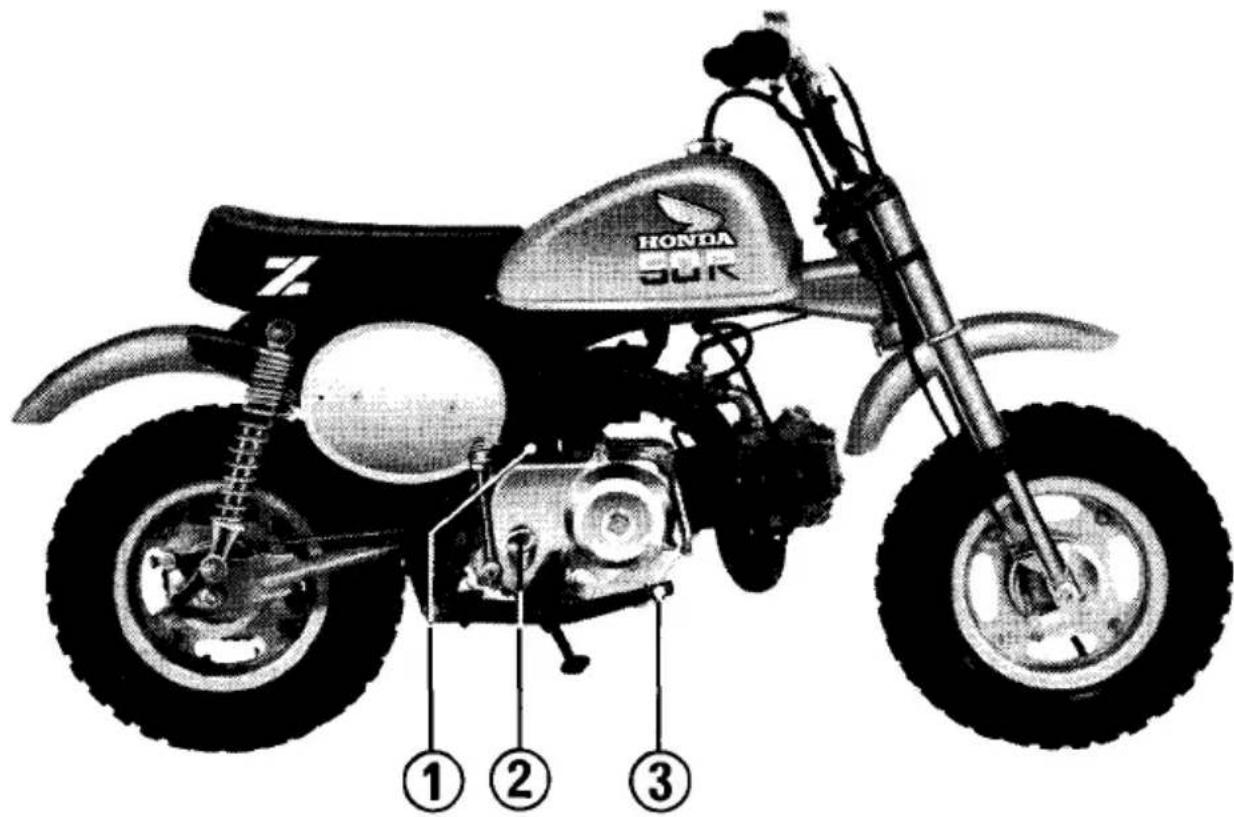
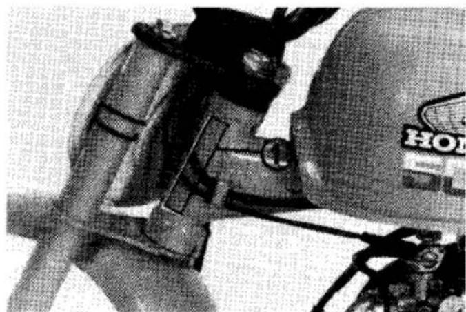
The spark plug wrench (1) and its handle (2) are attached to the bottom of the seat.
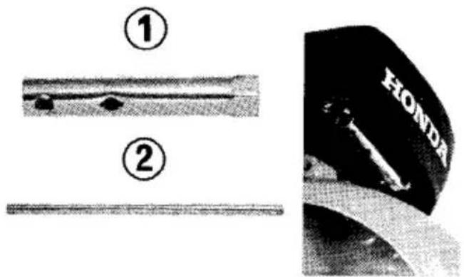
(1) Spark plug wrench
(2) Handle
MAINTENANCE
- The U.S. Environmental Protection Agency requires manufacturers to certify that motorcycles built after January 1, 1983 comply with applicable noise emission standards for one year or 3,000 km (1,865 miles) after the time of sale to the ultimate purchaser, when operated and maintained according to the instructions provided. Compliance with the terms of the Distributor's Warranty for the Honda Motorcycle Noise Emission Control System is necessary in order to keep the noise emission control system in effect. (USA only)
- The maintenance intervals shown in the following schedule are based upon average riding conditions. Machines subjected to severe use, or ridden in muddy or dusty areas require more frequent servicing.
- Consult your authorized Honda dealer for recommendations applicable to your individual needs and use.
- If your motorcycle is involved in a collision, have your Honda dealer inspect the major components including frame, suspension and steering parts for misalignment or damage.
WARNING
* Stop the engine and support the motorcycle securely on a level surface before performing any maintenance.
* Use new, genuine Honda parts or their equivalent for maintenance and repair. Parts which are not of equivalent quality may impair the safety of your motorcycle.
MAINTENANCE SCHEDULE
Items marked * should be serviced by an authorized Honda dealer or by a qualified service facility that normally does this kind of work; or you may perform most
of the work yourself if you are mechanically qualified and have the proper tools. Refer to the official Honda Shop Manual.
I: Inspect and Clean, Adjust, Lubricate, or Replace, if necessary.
C: Clean. R: Replace. A: Adjust. L: Lubricate.
| NOTE:(1) Replace every 30 operating days or every 3 months, whichever comes first.(2) Service more frequently when riding in dusty areas. | INITIAL SERVICE PERIOD(First week of operation) | REGULAR SERVICE PERIOD(Every 30 operating days) | Refer to page | ||
| ENGINE OIL | NOTE(1)(2) | R | R | 27 | |
| * | CONTACT BREAKER POINTS | I | I | 29 | |
| * | IGNITION TIMING | I | I | 29 | |
| * | VALVE CLEARANCE | I | I | 30 | |
| SPARK PLUG | I | 28 | |||
| * | CARBURETOR | I | I | 36 | |
| AIR CLEANER ELEMENT | NOTE (2) | C | 33 | ||
| INITIAL SERVICE PERIOD(First week of operation) | REGULAR SERVICE PERIOD(Every 30 operating days) | Refer to page | ||
| THROTTLE CABLE | I | I | 35 | |
| FUEL LINE | I: (EVERY YEAR) | - | ||
| * | FUEL FILTER | C: (EVERY YEAR) | 37 | |
| DRIVE CHAIN | I | I | 38 | |
| * | CLUTCH | I | I | 37 |
| SPARK ARRESTER | C | 34 | ||
| BRAKE CONTROL LINKAGE | I | I | 42 | |
| * | BRAKE SHOES | I: (EVERY YEAR) | 43,45 | |
| * | STEERING HEAD BEARING | I: (EVERY YEAR) | - | |
| TIRES | I | I | 15 | |
| ALL NUTS, BOLTS, FASTENERS | I | I | - | |
Engine Oil
Engine oil quality is the chief factor affecting engine service life. Change the engine oil when specified by the Maintenance Schedule.
NOTE:
* Change engine oil with the engine warm and the motorcycle held upright to assure complete and rapid draining.
natural_image
Close-up of a mechanical component with numbered annotation (1) and no visible text or symbols(1) Drain plug
-
Remove the oil filler cap/dipstick and drain plug (1) to drain the oil.
-
After the oil has completely drained, make, sure the sealing washer is in good condition and install the drain plug.
Drain plug torque: 20–25 N.m (2.0–2.5 kg-m, 14–18 ft-lb)
-
Fill the crankcase through the oil filler opening with approximately 0.7ℓ(0.74 U S qt), of the recommended grade oil, (see page 14).
-
Install the oil filler cap/dipstick.
-
Start the engine and let it idle for a few minutes.
-
Stop the engine.
-
Make sure that the oil level is at the upper level mark with the motorcycle in an upright position, and that there are no oil leaks.
Spark Plug
Recommended plug:
Standard:
CR6HS (NGK) or U20FSR-U (ND)
-
Clean any dirt from around the spark plug base.
-
Disconnect the spark plug cap, and remove spark plug.
-
Visually inspect the spark plug electrodes for wear. The center electrode should have square edges and the side electrode should not be eroded. Discard the spark plug if there is apparent wear or if the insulator is cracked or chipped.
-
Make sure the spark plug gap (1) is 0.6–0.7 mm (0.024–0.028 in) using a feeler gauge. If adjustment is necessary, bend the side electrode (2) carefully.
-
With the plug washer attached, thread the spark plug in by hand to prevent cross-threading.
-
Tighten a new spark plug 1/2 turn with a spark plug wrench to compress the washer. If you are reusing a plug, it should only take 1/8-1/4 turn after the plug seats.
CAUTION:
* The spark plug must be securely tightened. An improperly tightened plug can become very hot and possibly damage the engine.
* Never use a spark plug with an improper heat range.
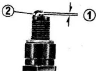
(1) Spark plug gap
(2) Side electrode
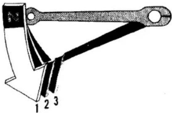
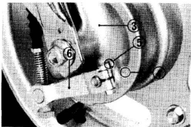
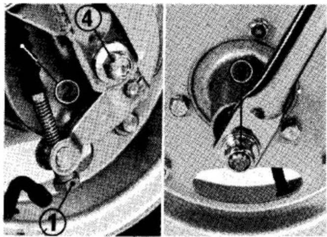
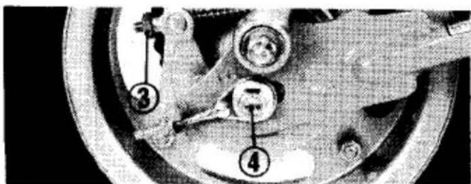
Contact Breaker Point Gap and Ignition Timing
Adjustment of the point gap and ignition timing are made at the same time. To adjust, proceed as follows:
- Remove the left crankcase cover screws, and remove the crankcase cover.
- Rotate the flywheel counterclockwise until the F mark (4) aligns with the index mark (3). Ignition timing is correct if the contact breaker points just begin to open at this moment.
- If ignition timing is incorrect, loosen the contact breaker locking screw (2) and adjust the breaker point gap.
(1) Contact breaker point gap
(2) Contact breaker locking screw
Increasing the gap will advance ignition timing. Decreasing the gap will retard ignition timing.
- Retighten the contact breaker locking screw and recheck ignition timing.
NOTE:
* Point gap must remain within limits of 0.3–0.4 mm (0.012–0.016 in) after ignition timing has been set. If correct timing results in a point gap which is outside these limits, replace the contact breaker points.
(3) Index mark (4) F mark
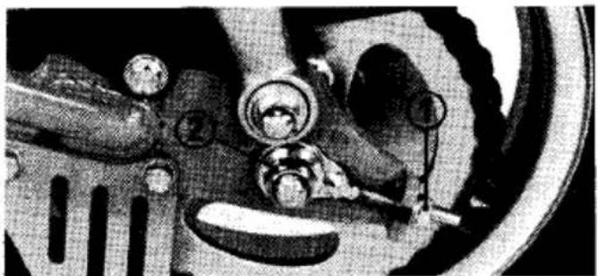
Valve Clearance
Excessive valve clearance will cause noise, and little or no clearance will cause valve damage and loss of power. Therefore, the valve clearance should be maintained properly. The valve clearance must be checked when the engine is cold.
NOTE:
* The checking or adjusting of the clearance should be performed while the engine is cold. The clearance will change as the engine temperature rises.
- Remove the left crankcase cover.
- Remove the adjusting caps.
- Rotate the generator flywheel counterclockwise until the T mark (2) on the flywheel lines up with the index mark (1) on the crankcase. In this position, the piston may either be on the compression or exhaust stroke.
The adjustment must be made when the piston is at the top of the compression stroke when both the intake and exhaust valves are closed.
This condition can be determined by moving the rocker arms. If they are free, it is an indication that the valves are closed and that the piston is on the compression stroke. If they are tight and the valves are open, rotate the
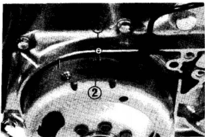
(1) Index mark
(2) T mark
flywheel 360° and realign the T mark to the index mark. Check the clearance of both valves by inserting the 0.05 mm (0.002 in) feeler gauge between the adjusting screw and the valve stem.
If it is necessary to make an adjustment, loosen the adjusting screw lock nut (4) and turn the adjusting screw (3) so there is a slight resistance when the feeler gauge (5) is inserted.
(3) Adjusting screw
(5) Feeler gauge
(4) Adjusting screw lock nut
After completing the adjustment, tighten the adjusting screw lock nut while holding the adjusting screw to prevent it from turning. Finally, recheck the clearance to make sure that the adjustment has not been disturbed. Reinstall the adjusting caps.
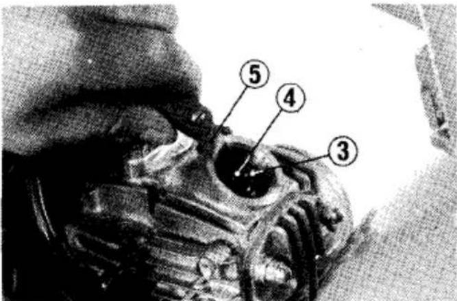
Cam Chain
When the cam chain is noisy, adjust the tension in the following manner:
- Start the engine.
-
Loosen the lock nut (1), and loosen the tensioner adjusting bolt (2) approximately one half turn. Tighten the lock nut.
-
If the chain is still noisy even after the above adjustment, loosen the lock nut (1) adjusting bolt (2) and the 14 mm sealing bolt located at the bottom of the crankcase, and screw in the tensioner bolt (3) gradually with the engine running, until the cam chain becomes quiet. After completing the adjustment, tighten the tensioner adjusting bolt, lock nut, and 14 mm sealing bolt securely.
(1) Tensioner adjusting bolt lock nut
(2) Tensioner adjusting bolt
(3) Tensioner bolt
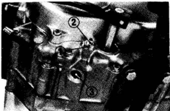
Air Cleaner
The air cleaner element must be cleaned and oiled at least once every 30 operating days. If your motorcycle is operated in dusty areas, more frequent servicing will be required. Your Honda dealer can help you to determine the correct service interval for your particular riding conditions.
- Remove the two attaching screws (1), the air cleaner case (2) and air cleaner element (3).
(1) Air cleaner cover attaching screws
(2) Air cleaner case
- Wash the air cleaner element in clean non-flammable or high flash point solvent and allow to dry thoroughly.
WARNING
* Never use gasoline or low flash point solvents for cleaning the air cleaner element. A fire or explosion could result.
-
Soak the air cleaner element in clean gear oil (SAE 80 SAE 90) until saturated, then squeeze out any excess oil.
-
Reinstall the air cleaner element.
-
Reinstall the air cleaner case.
natural_image
Close-up of mechanical components with no visible text or symbols(3) Air cleaner element
Spark Arrester
The exhaust system spark arrester must be purged of accumulated carbon periodically (see the Maintenance Schedule for servicing period).
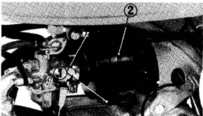
- Remove the right hand number plate. Remove the diffuser pipe (1) by removing the securing bolt (2).
WARNING
* Do not perform this operation immediately after the engine has been run because the exhaust system becomes very hot.
-
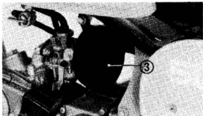
Remove the carbon trap clean out cap (3).
-
Start the engine and rev it several times while blocking the end of the exhaust pipe with a rag.
WARNING
* Because of the increased fire hazard ensure that there are no combustible materials in the area when purging the spark arrester.
* Wear eye protection. * Never run the engine in a closed area. The exhaust contains poisonous carbon monoxide gas.
-
After clearing the carbon from the trap, reinstall the clean out cap and tighten securely.
-
Remove the carbon from the diffuser pipe and reinstall it. Install the number plate.
(1) Diffuser pipe (2) Securing bolt
natural_image
Close-up of a mechanical component with numbered annotation (3) and no visible text or symbols(3) Clean out cap
Throttle Cable
Check for smooth rotation of the throttle grip from the fully closed to the fully open position. Check at full left and full right steering positions. Inspect the condition of the throttle cable from the throttle grip down to the carburetor. If the cable is kinked, chafed or improperly routed, it should be replaced and/or rerouted.
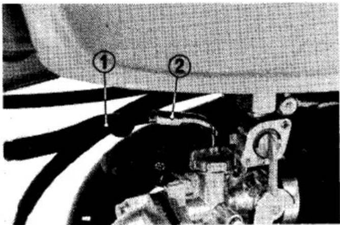
(1) Rubber cap
(2) Throttle cable adjuster
WARNING
* For safe operation and positive engine response, the throttle cable must be properly adjusted.
Standard throttle grip free play is approximately 2–6 mm (1/8–1/4 in) of grip rotation. Adjust free play with the throttle cable adjuster (2).
Turn the adjuster to obtain 2–6 mm (1/8–1/4 in) of throttle grip free play.
Lubricate the cable with a commercially available cable lubricant to prevent premature wear and corrosion.
Carburetor
Idle Speed
The engine must be warm for accurate idle adjustment. Ten minutes of stop-and-go riding is sufficient.
NOTE:
* Do not attempt to compensate for faults in other systems by carburetor adjustment. See your authorized Honda dealer for regularly scheduled carburetor adjustments.
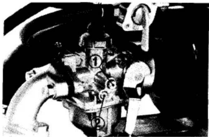
(1) Throttle stop screw
(2) Air screw
- Warm up the engine and hold the motorcycle upright.
- Adjust idle speed with the throttle stop screw.
IDLE SPEED: 1,500±100 rpm
Fuel Mixture
- Adjust the fuel mixture by turning the air screw (2) clockwise until you hear the engine miss or decrease in speed, then counterclockwise until the engine again misses or decreases in speed. Center the air screw exactly between these two extreme positions. Usually the correct setting (between extremes of rich and lean) will be found to be 1-1/2 turns open from a fully closed position.
- If idle speed changes after adjusting fuel mixture, readjust the idle speed by turning the throttle stop screw.
Fuel Filter
The fuel filter is incorporated in the fuel valve which is mounted on the bottom of the fuel tank on the left side. Accumulations of dirt in the filter will restrict the flow of fuel and cause the carburetor to malfunction; therefore, the fuel filter should be serviced periodically by your authorized Honda dealer.
Clutch
To adjust the clutch:
- Loosen the adjuster lock nut (1).
- Turn the clutch adjuster (2) clockwise one turn; do not turn excessively.
- Slowly turn the adjuster counterclockwise until a slight resistance is felt.
- From this position, turn the adjuster clockwise 1/8 to 1/4 turn, and tighten the lock nut.
- After adjustment, test ride the motorcycle to be certain the clutch operates properly.
The engine should start easily with the kickstarter without the clutch slipping. When shifting gears, the clutch operation should be smooth and light, especially when shifting into neutral.
NOTE:
* If proper adjustment cannot be obtained or the clutch does not work correctly, see your authorized Honda dealer.

(1) Lock nut
(2) Clutch adjuster
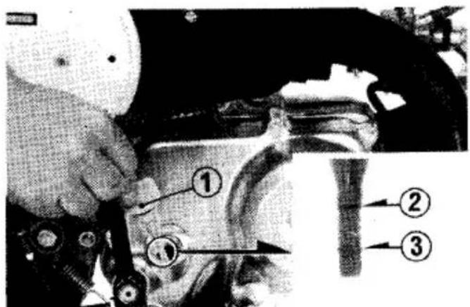
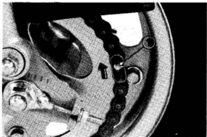
Drive Chain
The service life of the drive chain is dependent upon proper lubrication and adjustment. Poor maintenance can cause premature wear or damage to the drive chain and sprockets. Under severe usage, or when the motorcycle is ridden in dusty areas, more frequent maintenance will be necessary.
Inspection:
- Turn the engine off, place the motor-cycle on the side stand and shift the transmission into neutral.
- Check slack in the lower drive chain run midway between the sprockets. Drive chain slack should be adjusted to allow 15–25 mm (5/8–1 in) vertical movement by hand.
- Roll the motorcycle and check drive chain slack as the wheel rotates. Drive chain slack should remain constant as the wheel rotates. If the chain is slack in one section and taut in another,
it indicates some links are worn, kinked, or binding. Kinking and binding can frequently be eliminated by lubrication.
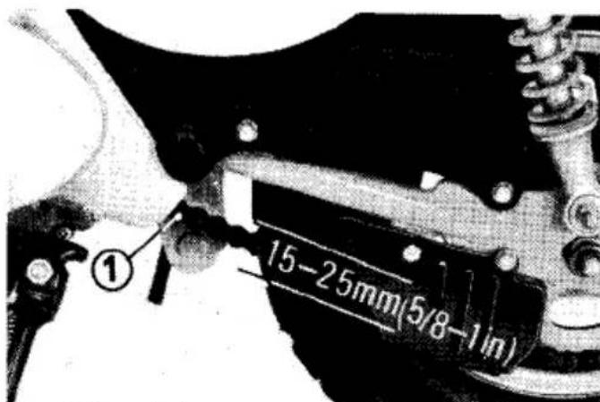
(1) Drive chain
- Inspect the sprocket teeth for wear or damage.

- If the drive chain or sprockets are excessively worn or damaged, they should be replaced. Never use a new chain with worn sprockets; rapid chain wear will result.
Adjustment:
If the drive chain requires adjustment, the procedure is as follows:
- Loosen the rear axle nut (1).
- Turn the adjusting nut (4) on both the right and left chain adjusters (5) an equal number of turns to increase or decrease chain slack. Align the chain adjuster index marks (2) with the corresponding scale (3) graduations on both sides of the swing arm.
NOTE:
* If the drive chain slack is excessive when the rear axle is moved to the furthest limit of adjustment, the drive chain is worn and must be replaced.
-
Torque the rear axle nut to 45-55 N·m (4.5-5.5 kg·m, 33-40 ft-lb)
-
Tighten the adjusting nuts.
-
Recheck drive chain slack.
- Rear brake pedal free play is affected when repositioning the rear wheel to adjust drive chain slack. Check rear brake pedal free play and adjust as necessary (page 44).
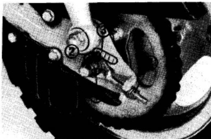
(1) Rear axle nut
(3) Graduated scale
(2) Adjuster index mark
(4) Adjusting nut
Lubrication:
Commercially prepared drive chain lubricants may be purchased at most motorcycle shops and should be used in preference to motor oil or other lubricants. Saturate each chain link joint so that the lubricant penetrates between the link plates, pins, bushings, and rollers.
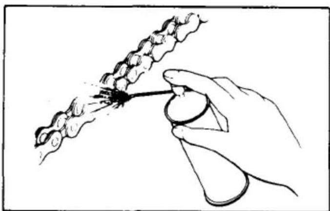
natural_image
Hand holding a tool interacting with a chain of chains, no text or symbols visibleRemoval and Cleaning:
When the drive chain becomes extremely dirty, it should be removed and cleaned prior to lubrication.
-
With the engine off, carefully remove the master link retaining clip (1) with a pair of pliers. Do not bend or twist the clip. Remove the master link. Remove the drive chain from the motorcycle.
-
Clean the drive chain in solvent and allow it to dry. Inspect the drive chain for possible wear or damage. Replace any chain that has damaged rollers loose fitting links, or otherwise appears unserviceable.
-
Inspect the sprocket teeth for possible wear or damage. Replace if necessary. Never use a new drive chain on badly worn sprockets. Both chain and sprockets must be in good condition, or the new replacement chain or sprocket will wear rapidly.
-
Lubricate the drive chain.
-
Pass the chain over the sprockets and join the ends of the chain with the master link. For ease of assembly, hold the chain ends against adjacent rear sprocket teeth while inserting the master link.
The master link is the most critical part affecting the security of the drive chain. Master links are reusable, if they remain in excellent condition, but it is
natural_image
Close-up of mechanical components with no visible text or symbols(1) Retaining clip
recommended that a new master link retaining clip be installed whenever the drive chain is reassembled.
Install the master link retaining clip (1) so that the closed end of the clip will face the direction of forward wheel rotation.
- Adjust the drive chain and rear brake pedal free play.
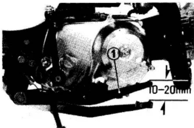
Front Brake
Adjustment:
Brakes are items of personal safety and should always be maintained in proper adjustment.
Free play, measured at the tip of the front brake lever (1), should be maintained at 10–20 mm (3/8–3/4 in). Free play is the distance the brake lever moves before the brake starts to engage.
- Adjust brake lever free play with the front brake adjusting nut (2). Turning the nut clockwise will decrease free play and turning the nut counterclockwise will increase free play.
Make sure the cut-out on the adjusting nut is seated on the brake arm pin.
- Apply the brake several times and check for free wheel rotation when released.
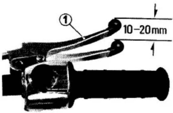
(1) Front brake lever
NOTE:
* If proper adjustment cannot be obtained by this method, see your authorized Honda dealer.
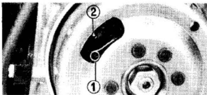
Wear indicator:
When the brake is applied, an arrow (5), attached to the brake arm (6), moves toward a reference mark (4) on the brake panel (3).
If the arrow aligns with the reference mark on full application of the brake, the brake shoes must be replaced.
See your authorized Honda dealer for this service.
natural_image
Close-up of a mechanical component with no visible text or symbols(2) Front brake adjusting nut
Other checks:
Check the brake cable for kinks or signs of wear that could cause sticking or failure. Lubricate the brake cable with a commercially available cable lubricant to prevent premature wear and corrosion.
Make sure that the brake arm, spring and fasteners are in good condition.
(3) Brake panel
(5) Arrow
(4) Reference mark
(6) Brake arm
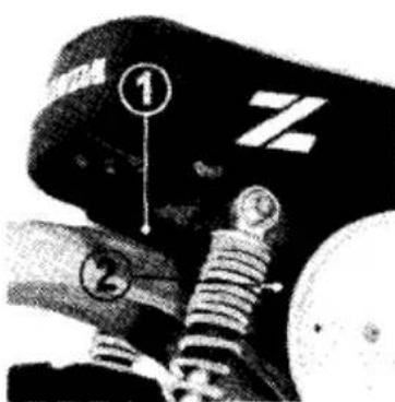
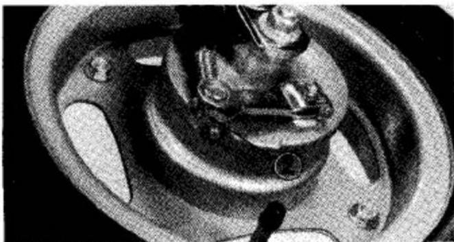
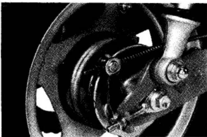
Rear Brake
To adjust the rear brake:
- Place the motorcycle on its side stand.
- Measure the distance the rear brake pedal (1) moves before the brake starts to take hold.
- Free play should be 10–20 mm (3/8–3/4 in). If adjustment is necessary, turn the rear brake adjusting nut (2).
(1). Rear brake pedal
Make sure that the cut-out on the adjusting nut is seated on the brake arm pin.
- Apply the brake several times and check for free wheel rotation when released.
NOTE:
* If proper adjustment cannot be obtained by this method, see your authorized Honda dealer.
natural_image
Close-up of a car brake system with suspension components (no visible text or symbols)(2) Rear brake adjusting nut
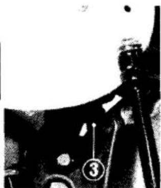
Wear indicator:
When the rear brake is applied, an arrow (3) attached to the rear brake arm (4) moves toward a reference mark (2) on the rear brake panel (1).
If the arrow aligns with the reference mark on full application of the rear brake, the brake shoes must be replaced. See your authorized Honda dealer for this service.
Other checks:
Make sure that the brake rod, brake arm, spring and fasteners are in good condition.
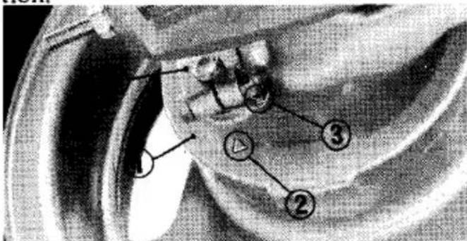
(1) Brake panel
(3) Arrow
(2) Reference mark
(4) Brake arm
Front Suspension
Check front fork action by locking the front brake and pumping the forks up and down several times. The suspension should function smoothly. If it is damaged or binding, the suspension should be repaired before the motorcycle is operated. Check the security of all front fork and handlebar mounting bolts.
WARNING
* If any suspension components appear worn or damaged, consult your Honda dealer for further inspection. The suspension components are directly related to safety and your Honda dealer is qualified to determine whether or not replacement parts or repairs are needed.
* Do not operate the motorcycle with loose, worn, or damaged steering or front suspension components, as handling will be adversely affected.
Rear Suspension
Check the rear suspension periodically by careful visual examination. Note the following items:
-
Swingarm bushing should be checked by pushing hard against the side of the rear wheel while the motorcycle is on a support block and feeling for looseness of the bushings.
-
Check all suspension component attachment points for security of their respective fasteners.
WARNING
* If any suspension components appear worn or damaged, consult your Honda dealer for further inspection.
Side Stand
Check the side stand spring for damage and loss of tension, and the side stand assembly for freedom of movement.
If the side stand is squeaky or stiff, clean the pivot area and lubricate the pivot bolt with clean engine oil.
Front Wheel Removal
- Raise the front wheel off the ground by placing a support block under the engine.
- Remove the front brake adjusting nut, (1) and remove the front brake cable (2) from the brake arm.
- Remove the axle nut (3).
- Remove the axle. Remove the wheel.
Installation Notes:
• Reverse the removal procedure.
- Tighten the axle nut to 45–55 N·m (4.5–5.5 kg·m, 33–40 ft·lb) torque.
- Adjust the brake (page 42).
- Apply the brake several times and check for free wheel rotation when released.
WARNING
* If a torque wrench was not used for installation, see your dealer as soon as possible to verify proper assembly.
(1) Front brake adjusting nut
(2) Front brake cable
(3) Front axle nut
(4) Front axle
Rear Wheel Removal
- Raise the rear wheel off the ground by placing a support block under the engine.
- Loosen the drive chain adjusting nuts (1) and remove the rear axle nut (2).
- Remove the chain joint clip and drive chain.
- Remove the rear brake adjusting nut (3) and separate the rear brake rod from the rear brake arm.
- Pull out the rear axle (4) and remove the rear wheel.
natural_image
Close-up of mechanical components with no visible text or symbols(1) Drive chain adjusting nut
(2) Rear axle nut
Installation Notes:
- Reverse the removal procedure.
- Tighten the axle nut to 45–55 N·m (4.5–5.5 kg·m, 33–40 ft·lb) torque.
• Install the chain joint clip with the closed end facing in the direction of chain rotation, (page 41). - Adjust the brake (page 44) and drive chain (page 38).
WARNING
* If a torque wrench was not used for installation, see your dealer as soon as possible to verify proper assembly.
- Apply the brake several times and check for free wheel rotation when released.
(3) Rear brake adjusting nut
(4) Rear axle
CLEANING
Clean your motorcycle regularly to protect the surface finishes and inspect for damage, wear, and oil seepage.
CAUTION:
* Avoid spraying high pressure water (typical in coin-operated car washes) at the following areas: Wheel Hubs Engine Stop Switch Muffler Outlet Under Fuel Tank Drive Chain Under Seat
- After cleaning, rinse the motorcycle thoroughly with plenty of clean water. Strong detergent residue can corrode alloy parts.
- Dry the motorcycle, start the engine, and let it run for several minutes.
-
Lubricate the drive chain immediately after washing and drying the motor-cycle.
-
Test the brakes before riding the motorcycle. Several applications may be necessary to restore normal braking performance.
WARNING
* Braking performance may be impaired immediately after washing the motor-cycle.
STORAGE GUIDE
STORAGE
Extended storage, such as for winter, requires that you take certain steps to reduce the effects of deterioration from non-use of the motorcycle. In addition, necessary repairs should be made BEFORE storing the motorcycle; otherwise, these repairs may be forgotten by the time the motorcycle is removed from storage.
- Change the engine oil.
- Lubricate the drive chain.
- Drain the fuel tank and carburetor. Spray the inside of the tank with an aerosol rust-inhibiting oil.
Reinstall the fuel cap on the tank.
WARNING
* Gasoline is flammable and is explosive under certain conditions. Do not smoke or allow flames or sparks near the equipment while draining fuel.
- Remove the spark plug and pour a tablespoon (15–20 cc) of clean engine oil into the cylinder. Operate the kick-starter several times to distribute the oil, then reinstall the spark plug.
NOTE:
* When turning the engine over, the Engine Stop Switch should be OFF and the spark plug placed in its cable cap and grounded to prevent damage to the ignition system.
- Wash and dry the motorcycle. Wax all painted surfaces. Coat chrome with rust-inhibiting oil.
- Inflate the tires to their recommended pressures. Place the motorcycle on blocks to raise both tires off the ground.
- Cover the motorcycle (don't use plastic or other coated materials) and store in an unheated area, free of dampness with a minimum of daily temperature variation. Do not store the motorcycle in direct sunlight.
REMOVAL FROM STORAGE
- Uncover and clean the motorcycle. Change the engine oil if more than 4 months have passed since the start of storage.
- Drain any excess aerosol rust-inhibiting oil from the fuel tank. Fill the fuel tank with fresh gasoline.
- Perform all Pre-ride Inspection checks (page 17). Test ride the motorcycle at low speeds in a safe riding area.
NOISE EMISSION CONTROL SYSTEM (USA ONLY)
TAMPERING WITH THE NOISE CONTROL SYSTEM IS PROHIBITED: Federal law prohibits the following acts or the causing thereof: (1) The removal or rendering inoperative by any person, other than for purposes of maintenance, repair, or replacement, of any device or element of design incorporated into any new vehicle for the purpose of noise control prior to its sale or delivery to the ultimate purchaser or while it is in use; or (2) the use of the vehicle after such device or element of design has been removed or rendered inoperative by any person.
AMONG THOSE ACTS PRESUMED TO CONSTITUTE TAMPERING ARE THE ACTS LISTED BELOW:
- Removal of, or puncturing the muffler, baffles, header pipes or any other component which conducts exhaust gases.
- Removal of, or puncturing of any part of the intake system.
- Lack of proper maintenance.
- Replacing any moving parts of the vehicle, or parts of the exhaust or intake system, with parts other than those specified by the manufacturer.
SPECIFICATIONS
| ITEM | |
| DIMENSIONS | |
| Overall length | 1,300 mm (51.2 in) |
| Overall width | 605 mm (23.8 in) |
| Overall height | 810 mm (31.9 in) |
| Wheelbase | 895 mm (35.2 in) |
| WEIGHT | |
| Dry weight | 49.5 kg (109.1 lbs) |
| CAPACITIES | |
| Engine oil | 0.8 ℓ (0.8 US qt) After disassembly |
| 0.7 ℓ (0.74 US qt) After draining | |
| Fuel tank | 5.0 ℓ (1.3 US gal) |
| Fuel reserve tank | 0.7 ℓ (0.18 US gal) |
| Vehicle capacity load | 68 kg (150 lb) |
| Passenger capacity | None, operator only |
| ENGINE | |
| Bore and stroke | 39.0 × 41.4 mm (1.54 × 1.63 in) |
| Compression ratio | 9.5 : 1 |
| Displacement | 49 cc (3.0 cu in) |
| Contact breaker point gap | 0.3 - 0.4 mm (0.012 - 0.016 in) |
| Spark plug | CR6HS (NGK) or U20FSR-U (ND) |
| Spark plug gap | 0.6 - 0.7 mm (0.024 - 0.028 in) |
| Valve clearance (cold) | 0.05 mm (0.002 in) |
| CHASSIS AND SUSPENSION | |
| Caster | 25° |
| Trail | 42 mm (1.7 in) |
| Tire size (front and rear) | 3.50-8-2PR |
| Tire pressure (front and rear) | 14 psi (100 kPa, 1.0 kg/cm2) |
| POWER TRANSMISSION | |
| Primary reduction | 3.722 |
| Final reduction | 2.846 |
| Gear ratio, 1st | 3.181 |
| 2nd | 1.823 |
| 3rd | 1.190 |
MEMO