CDX-GT970US - CD-afspiller SONY - Gratis brugsanvisning og manual
Find enhedens vejledning gratis CDX-GT970US SONY i PDF-format.

Brugerspørgsmål om CDX-GT970US SONY
0 spørgsmål om dette apparat. Besvar dem du kender, eller stil dit eget.
Stil et nyt spørgsmål om dette apparat
Download vejledningen til din CD-afspiller i PDF-format gratis! Find din vejledning CDX-GT970US - SONY og tag din elektroniske enhed tilbage i hånden. På denne side er alle dokumenter nødvendige for brugen af din enhed offentliggjort. CDX-GT970US af mærket SONY.
BRUGSANVISNING CDX-GT970US SONY
SONY.
3-283-553-31 (1)
FM/AM Compact Disc Player
Installation/Connections
Instalación/Conexiones
نصب/اتصالات
CDX-GT970US
© 2008 Sony Corporation Printed in Thailand
=
|||


Front speaker Altavoz frontal بندگوی جنوبی

Rear speaker Altavoz posterior بندگوی عقیس

Active subwoofer Altavoz potenciador de graves activo ووفر فرعى ل №ال

Power amplifier Amplificador de potencia تقويت كننده نېرو


Rotary commander RM-X4S Mando rotatorio RM-X4S RM-X4S فرمان دهنده گردان

USB device Dispositivo USB USB
Cautions
- This unit is designed for negative ground (earth) 12 V DC operation only.
- Do not get the leads under a screw, or caught in moving parts (e.g. seat railing).
- Before making connections, turn the car ignition off to
- Before heating connections, then the -lighted cell to avoid short circuits.
- Connect the yellow and red power supply leads only
• Run all ground (earth) leads to a common
ground (earth) point. - Be sure to insulate any loose unconnected leads with
electrical tape for safety. Notes on the power supply load (yellow) - When connecting this unit in combination with other stereo components, the connected car circuit's rating
must be higher than the sum of each component's fuse. When no car circuits are rated high enough, correct
When the bus defaults are fixed high enough, connected the unit directly to the battery.
Parts list 1
- The numbers in the list are keyed to those in the instructions.
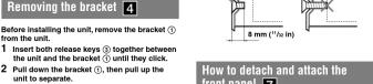
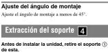
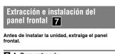
- The bracket ① is attached to the unit before shipping. Before mounting the unit, use the release key ② to
Before mounting the unit, the release keys (6) to remove the bracket ① from the unit. For details, see "Removing the bracket (4)" on the reverse side of the
sheet. - Keep the release keys ③ for future use as they are also necessary if you remove the unit from
your car. Caution
instructions. - The bracket ① is attached to the unit before shipping. Before mounting the unit, use the release keys ③ to
remove the bracket ① from the unit. For details, see "Removing the bracket (4)" on the reverse side of the
Removing the bucket (1-4) on the reverse side of the sheet. - Keep the release keys ③ for future use as the are also necessary if you remove the unit from
are also necessarily if you remove the car from your car.
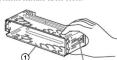
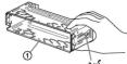
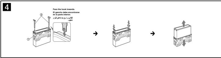
Handle the bracket ⑤ carefully to avoid injuring your fingers.

Before installing, make sure that the catches on both sides of the bracket ① are bent inwards 2 mm ( 110 in). If the catches are straight or bent outwards, the unit will not be installed securely and may spring out.
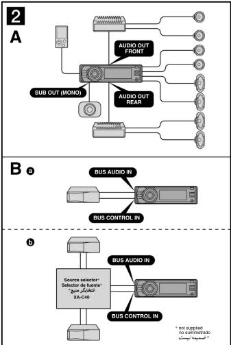
Connection example 2
Notes (2-A)
- Be sure to co the amplifier.
- The alarm will only sound if the bell-in amplifier is used.
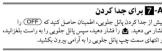
Tip (F-9-0)
For connecting two or more CD/MD chargers selector XA-C40 (not supplied) is necessary.
Notes (2-A)
- Be sure to connect the ground (earth) lead before connecting the amplifier.
- The alarm will only sound if the built-in amplifier is used.
For connecting two or more CD/MD changers, the source
Connection diagram 3
① To a metal surface of the car First connect the black ground (earth) le
- The electric air dust/glass (dark) lead with sensitive the yellow and red power supply loads.
- To the power antenna (serial) control lead or
To the power antenna (aerial) control lead of power supply lead of antenna (aerial) booster
Notes
- It is not necessary to connect this lead if there is no power
antenna (aerial) or antenna (aerial) booster, or with a manually-operated telescopic antenna (aerial).
- When your car has a built-in FMAM antenna (serial) in the rearside glass, see "Notes on the control and power supply orders."
③ To AMP REMOTE IN of an optional power
amplifier
This connection is only for amplifiers. Connecting any other
④ To the interface cable of a car telephone
⑤ To a car's illumination signal
Be sure to connect the black ground (earth) lead to a metal
surface of the car first.
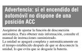
A To the +12 V power terminal which is
- To the 142 power terminal which is energized in the accessory position of the ignition switch.
Notes
a) if there is no necessary position, respect to the .47.1
- If there is no accessory position, connects to the +12 V power (battery) terminal which is energized at all times.
Be sure to connect the black ground (earth) lead to a metal surface of the car first.
- When you can be a built-in EU/AM antenna (serial) in
- When your car has a brown Ti-MeAs starch (bents) in the rearside glass, see "Notes on the control and power supply leads."
⑦ To the +12 V power terminal which is energized at all times
Be sure to connect the black ground (earth) lead to a metal surface of the car first.
Notes on the control and power supply leads
- The power antenna (serial) control lead (blue) supplied +12 W DC when you turn on the tuner. - When your car has built-in FM/AM antenna (serial) in the rear.
When your ear has been in a series of similar (serial) in the room-side glass, connect the power antenna (aerial) control lead (blue) or the accessory power supply lead (red) to the power
(please) of the necessary power supply kits (red) to the power terminal of the existing antenna (aerial) booster. For details, consult your dealer.
- A power antenna (aerial) without a relay box cannot be used with this unit.
Memory hold connection When the yellow power supply lead is connected, power will
always be supplied to the memory circuit even when the ignition switch is turned off.
Notes on speaker connection • Below connecting the speakers, turn the unit off
- Use speakers with an impedance of 4 to 8 ohms, and with adequate power handling capacities to avoid its damage.
- Do not connect the speaker terminals to the car chassis, or connect the terminals of the right speakers with those of the
left speaker. - Do not connect the ground (earth) load of this unit to the
negative (−) terminal of the speaker. - Do not attempt to connect the speakers in parallel.
- Connect only passive speakers. Connecting active speakers (with built-in amplifiers) to the speaker terminals may damage
the unit. - To avoid a malfunction, do not use the built-in speaker leads
installed in your car if the unit shares a common negative (−) lead for the right and left speakers.
- Do not connect the unit's speaker leads to each other.
Now on connection If speaker and amplifier are not connected correctly, "FAILURE"
appears in the display. In this case, make sure the speaker and amplifier are connected correctly.
Diagrama de conexión 3
Precauciones
- Esta unidad se diseñó para alimentarse sólo con cc de 12 V de masa negativa.
- No coloque los cables debajo de ningún tornillo, ni los abrasione con partes móviles (n. e), los raíles del
Los operadas que para el valor (p. 1) de rualles del asiento).
- Antes de realizar las conexiones, desactive el encendido del automóvil para evitar cortocircuitos.
- Conecte los cables de entrada de alimentación amarillo y rolo solmente después de haber
conectado los demás.
- Conecte todos los cables de conexión a masa a un punto común.
- Por razones de seguridad, asegúrese de aislar con cinta vislante los cables ueltos que no están conectados.
Notas sobre el cable de fuente de alimentación
(amarillo)
- Cuianas concele esta utilidad en combinación con otros componentes estéreo, la capacidad nominal del circuito
conectado del automóvil debe ser superior a la suma del fusible de cada componente.
- Si no hay circuitos del automóvil con capacidad
bomatal sullesiemente alta, conecte la unidad directamente a la batería.
The Ground Truth image displays a single, solid horizontal line. According to Rule 2 (UNDERSCORE & LINE RULES), if the GT contains lines used for stylistic emphasis or as background elements (like ruled paper), the OCR result must ignore them. The line in the GT is clearly a stylistic or background line, not a placeholder for text. Therefore, the OCR should not have output any underscores. Outputting `____` constitutes an error under Rule 2, as it hallucinates placeholder symbols where none are semantically intended. Hence, the OCR result is inconsistent with the Ground Truth.
Lista de componentes 1
- Los números de la lista corresponden a los de las
instrucciones. - La unidad de Compañía con el presente ①. Antes
- La unidad se comercianiza con el sopole (1). Alles de montarla, utilice las llaves de liberación (2) para
extraer el soporte ① de la unidad. Para obtener más información, consulte "Extracción del soporte (6)1" en
el dorso de la hoja.
- Conserve las llaves de liberación ① para utilizarias en el futuro, ya que también las
necesitará si retira la unidad del automóvil.
Precaución
Tenga mucho ciudados al manipular el sopore (5) para evitar posibles lesiones en los dedos.
Nota Antes de instalar la unidad, compruebe que los enganches de
ambos lados del soporte (1) están doblados hacia dentro 2 mm. Si no lo están o están doblados hacia afuera, la unidad no se
instalará correctamente y puede saltar.
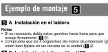
Eiemplo de conexiones 2
Ejemplo de conexiones
Notas (2-A) - Asegúrea de aspectas primer el cable de conquete a masa
- Hugarose de conócular primero el cable de sinaldo a hasta antes de realizar la conexión del amplificador. - La alarma sopará únicamente si se utiliza el amplificador.
- La Martina sonado enciamierto de se grazo de ampliobasir incorporado.
Sugerencia (B-B-O) Si desea conectar dos o más cambiadores de CD/MD,
necesitará el selector de fuente XA-C40 (no suministrado).
① A una superficie metálica del automóvil Correcte nitzero el cable de conexión a masa negro, y después
Los cables amarillo y rojo de entrada de alimentación.
Al cable de control de la antena motorizada o al cable de fuente de alimentación del
amplificador de señal de la antena
Notas - Si no se dispone de antenna motorizada ni de amplificador
de antena, o se utiliza una antena telescópica accionada manualmente, no será necesario conectar este cable.
- Si el automóvil incorpora una antena de FM/AM en el cristal trasero o lateral, consulte "Notas sobre los cables de control y
de fuente de alimentación".
A AMP REMOTE IN DE UN AMLIFICADOR DE potencia opcional
Esta conexión es solo para amplificadores. La conexión de cualquier otro sistema puede dañar la unidad.
④ Al cable de interfaz de un teléfono p automóvil
⑤ A una señal de iluminación del automóvil
Asegúrese da conectar primero el cable de conexión a masa negro a una superficie metálica del automóvi.
⑥ Al terminal de alimentación de +12 V que
recibe energía en la posición de acc interruptor de la llave de encendido
Notas - Si no hay posición de accesorio, contradicto al terminal de
- Or hay posión de dosolor, considio al terminar de alimentación (batería) de +12 V que recibe energía sin integración.
Asegúrese de conectar primero el cable de conexión a mas
- Si el automóvil incorpora una antena de FM/AM en el cristal
Insero o lateral, consorte "Notas sobre los cables de control y de fuente de alimentación".
Al terminal de alimentación de +12 V que recibe energía sin interrupción
Asegúrese de conectar primero el cable de conexión a masa, como o una superficie metófica del su Armiardi.
Notas sobre los cables de control y de fuente de alimentación
- El cable de control de la antena motorizada (azul) suministrará oc de + 12 V cuando conecte la alimentación del sintonizador.
- Si el automóvil dispone de una antena de FM/AM incorporada en el cristal trazero o lateral, conecte el cable de control de antena
motorizada (azul) o el cable de entrada de alimentación auxiliar (roici) al terminal de alimentación del amplificador de antena
existente. Para obtener más información, consulte a su distribuido - Con esta unidad no es posible utilizar una antena motorizada sin
caja de reló.
Conexión para protección de la memoria Si conecta el cable de entrada de alimentación amarillo, el circuito
de la memoria recibirá siempre alimentación, aunque apague el interruptor de encendido.
Notas sobre la conexión de los altavoces - Antos do conectar los altavones, disconcerto la alimentación de
- Aries de correctar los intervoces, desconoce la alimentación de la unidad. - Utilio altvones con una impodencia de 4 a 8 (2) con la capacidad
- Oficio analizadores con una impedancia de 4 a 0.11 con la capacidad de potencia adecuada para evitar que se dañen. - No respecto los tominales de altarca al obras del automévil, ni
- No correcte los terminales de altavoz, al crisis del automone, no conecte los terminales del altavoz derecho con los del izquierdo. - No consento el sabío de conferición a mayo de esta unidad al
- No correcte en close de corexion a finada de esta unidad al terminal negativo (−) del alta»oz.
- No interna conectar los altavocidos en paralleb. - Conecte solamente altavoces pasivos. Si conecta altavoces
activos (con amplificaciones incorporadas) a los territoriales de altavoz, puede darlar la unidad.
Para evitar falsa de funcionamiento, no unice los días de altavoz incorporados instalados en el automóvil si la unidad
comparte un cable negativo común (−) para los altavoces derecho e izquierdo.
- No conecte los cables de altavaz de la unidad entre s.l. Nota sobre la conseñón
Si el altavoz y el amplificador no están correctados correctamente aparecerá "FAIL LRF" en la portalla. Si es así, compuve la
eparacenta 1 M2O 12" en la panilla. Of el dos, complosse la conexión del altavoz y el amplificador.
3 نمودار اتصال
١ به یک سطح فلزی اتومیل
ابلا سبم سباه زمین را وصل کلید، سبس سبم های منام برق زرد و قرészرا وصل کلید.
به سيم کتترل آنتن هوايى برقى ۵۱ سيم منبع برق تقویت
کننده هوايى
• فر صورت که آنین هواپی رار قریکا ۱ کلويت کنیده هواپی وجرد نداری (۱)
يک آشن هوای کلکوی کدی وصل کردان آین سیم فصروری لیست.
• متحامى له الومیل لها داراق يکف اشن هواي لله عَتَى / کتاری م. بالشد، "نکات در مورد سیم های کتراز و
منج برق، را ملاحظه نهايد.
يک تقویت کننده نیرو اختياری AMP REMOTE IN به
دېگرى مكن است دستگاه را خراب کد.
٣ به کابل ایترفیس تلدن یک اتومیل
٢٥ به سیکتال روتستایی یک الومبیل
بِهَ ترمینال برق ١٣٥ ولَنْ
احتراق نیرو می نیرد
• اکر هیجر موقعت جائی، retirement لدارد، به تر مسال برق (بایطري)
۱۲۰ رکت که همواره نجرو می گیرد رصل کنید.
اฒمینان حاصل کنید که آبندا سیم سیاه زمین را به سطع فلزی
• مکام که اتوISA. لسایداری کیک آکن. مواس. FMAM
شبله علیم/کتاری می باشد، نکات در مورد سبم های کترال و
ملاوي برق، را ملا inhibة نهاب Chad.
الحصاني حماسا، كنام كه انتاً جام صناء مزن راً ٥٤ صنج فلأي ١٠ وست دا شفوارة يزرو ملى ييرد
ات در مورد سيم هاكى كتشرل و منبع برق
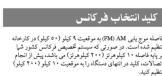
مکامی که شنا موج پاب را روشن می کنید سیم کترل انتن هوای ۶۰۴ (الس) - سف مکم + ۱۳ و استدًا لامین می کن.
منگاسی که اتومیا. تنا دارای یک آنتن: هواهی, در تبینه FMAM
عَقَلِي / كُنَارِي مِي بِاشُفْ سِيم كُتَرِلَ أَتَّن هُوايى بِرِقِي (آي) بِ سِيم منَح
براي جامى (قُر Metro) راً به قر Metroات براي تطويت لستنده المئ قواي م baggage وصل کتید: براي جزلياش، با فروشتمه خود مشورت نأيید.
يکه آنن هواکی بدون یک ایستگاه لقویت لمی لواند با این دستگاه مورد
الإستعمال مراز كرد الصال حفظ حافته
هنگامی که سیم منبع برق زرød وصل می شود، برق هیشه به مدار حانطه
ت در مورد اتصال بندگه
يッチ لز وصل کردان بلتندگوه، دستنگاه را خاموشر کتید.
الزبلتندکلورها با اسیدانس ۶ لا۸ آهم، وبا طرفیت پالای برق استفاده کید الناز صیدویم آنر جلوگی ک. کنقد
ترمیال های یلندگورا به لسای ارumsیل وصل تکنید با ترمیال های
بندگورهای راست را به ترمینال های بندگورهای چپ وصل تکید. سیم: مدن آمن دستگاریا بوت صالد مف. (–) بندگو وصل کنید.
سی نکنید بلندگرها را بطور موزی وصل کنید.
تُنَا بِمْدَكُرْهَاي نُجْرَ فَعَال رَا وَصْلَ كَنَّدِ وَصْلَ كَرْدِبِ بِمْدَكُرْهَاي فَعَال أَبَا لَقُمْرِت
برای اجتناب ازیک سوه، عملکرد، از سیم های پلندگری دانGLÍ لNPب
لُنَدَهِ در الْمِبِيلِ لَحُودَدِرَ صورَالِي كَهِ مِسْتَكَاءَ دَارَانِ يَكِ سَيم مُشْفِي (١)
• سيم های بکندگوی دستگاه را به یکندگر رصل کنید.
لكله در مورد اتصال
"FAILURE"
حاصل کنید که پلیدگور و تقویت کنیده بطور صحیح نسب شده اند.
احтировات
• این دستگاهتها برای عملیات برق مستطیم ۱۳ ولت مفی زمین طراحي
• سیمرازیر یک بیچ قرار ندهید، یا میان قطعات متحر ک (یرای مثال ریا)
ص(||تى) كېر ندهيد.
کولنام جلوو گیری کنید: کلیل ار الجد ۱۳۰۵ تکلیا احتراق مروخیل را حاسویس کید ۶۰۲۹ ور کلیل ۱۳۰۵ تکلیا ۱۳۰۵ تکلیا ۱۳۰۵ تکلیا ۱۳۰۵ تکلیا ۱۳۰۵ تکلیا ۱۳۰۵ تکلیا ۱۳۰۵ تکلیا ۱۳۰۵ تکلیا 1
• سيم های منبع يرق نزید و قرهز راتhetا هنگانی که سلیر سبم ها وصل
• تمام سسر های زمن: رایه بک نقطه مشتر کی زمن: بکشید.
• اطلمیتنان حاصل کتید که به منظور اینی هر سیم وصل لشده شل را رها
نوار برفي عابق بندی کید.
• هنگام وصل کردن این دستگاه در تركیب یا اجزای استاریو دیدگر، سطمر
midار الوميل وصل شده باید از مجموع هر فیوز اجزا بالاتر باشد.
مُحْتَلِي بِه بِأَرْرِي وَرَصْلَ كَنْدَ.
1 لیست قسمت های
• تهاره ها در لیست با تهاره ها در دستورالعمل ها مطایق لنده اند.
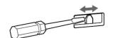
• قلاب ① يش از ارسال به دستگاه وصل شده است. قبل از نXP
دستگاه، از کلیدهای آزادسازی ① برای خارج کردن قلاپ ① از
دستكاء استفاده کنید. برای جزیلات، خارج کردی قلاب (۳)
در سمعت پیشکت بر که را ملاحطه نیاپید، کاند ۶۰۱- لیکساین ۶۰۱- ③ را ای ۶۰۱- ایکساین ۶۰۱- آنده نگالیم ۶۰۱- و ای
الجانيكله أن ها در صورتى، كە شما دستكاه را از التوميل خود
خارج كنید نبز ضروری هستند.
الحصّط
本报告书(以下简称“本报告”)的披露信息如下:
بُشْرِ الْتَحِبِ، اطْمِنَانِ حَمَّاِلِ كَنْدِ كَه گیره هَا دَرْهِر دُو طَرْف قَلَاب
① ملیبتر به سمت داخل خم للدهاند. آگر گیره ها صاف مستد یا به
است به بروان ي ثات لود.
نمونه ال
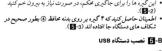
• اطینان حاصل کنید که سیم ز Oman (ارش) را پیش از وصل کردن
• تجها د صورا کال قويت کننده فلاید سر داسخاس وقار گم دا نکیس
صنا در خواهدآمد.
(2-0-6) ماره
برای وصل کردت دو تعويض کتنده CD/MD ۱ا پیشک، انتخابکر منبع
الإربة بت (صروزی است. 2014-140)
Front speaker Altavoz frontal
05年1月
Rear speaker Altavoz posterior
•

Active subwoofer Altavoz potenciador de graves activo
العربية
[Non-Text]

CD/MD changer Cambiador de CD/MD CD/MD تغیر دهندده


1.2.3
Parts list 1
• The numbers in the lis
Caution
Handle the bracket (i) carefully to avoid injuring your fingers.
30
[Non-Text]
B
-
-
-
-
-
-
-
-
-
-
-
-
-
-
-
-
-
-
-
-
-
-
-
-
-
-
-
-
-
-
-
-
-
-
-
-
-
-
-
-
-
-
-
-
-
-
-
-
-
-
-
-
-
-
-
-
-
-
-
-
-
-
-
-
-
-
-
-
-
-
-
-
-
-
-
-
-
-
-
-
-
-
-
-
-
-
-
-
-
- 91.
-
-
-
-
-
-
-
-
-
-
-
-
-
-
-
-
-
-
-
-
-
-
-
-
-
-
-
-
-
-
-
-
-
-
-
-
-
-
-
-
-
-
-
-
-
-
-
-
-
-
-
-
-
-
-
-
-
-
-
-
-
-
-
-
-
-
-
-
-
-
-
-
-
-
-
-
-
-
-
-
-
-
-
-
-
-
-
-
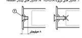
①
Catch
Before installing, make sure that the catches on both sides of
the bracket (1) are bent inwards 2 mm ( 10 in). If the catches are straight or bent outwards, the unit will not be installed securely
and may spring out.
Connection example
Connection example 2
безалл ХРОЛУ (на здарию) IS NECESSARY.

lead for • Do not
text_image
Face the hook inwards. El gancho debe encontrarse en la parte interior.### ### ### ###
### ### ###

text_image
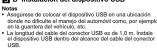
5 A 1 180 mm 53 mm Class Units a x a 2 3 Dashboard Tablets ① ④ ⑥ ⑦ Fire wall Coniferungs/ ###
B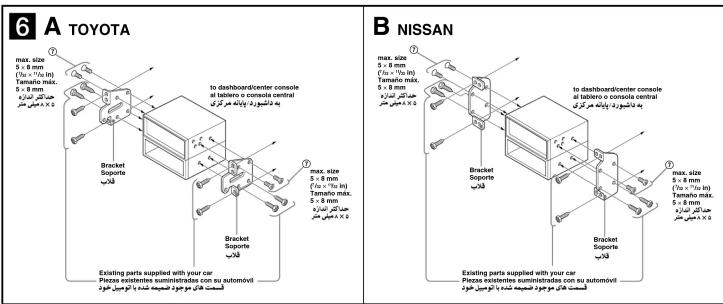
text_image
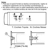
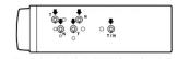
6 A TOYOTA max. size 5 x 8 mm (Ta/10" + T/m) in Tamaño máx. 5 x 8 mm 4 x 8 mm Max. size 5 x 8 mm (Ta/10" + T/m) in Tamaño máx. 5 x 8 mm 4 x 8 mm Bracket Soporte Existing parts supplied with your car Pieces existentes suministradas con su automóvil to dashboard/center console at taillero o console central bracket Soporte Existing parts supplied with your car Pieces existentes suministradas con su automóvil to dashboard/center console at taillero o console central bracket Soporte Existing parts supplied with your car Pieces existentes suministradas con su automóvil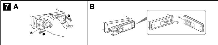
text_image
7 A B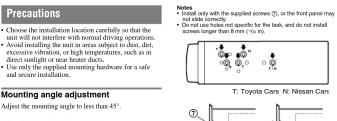
text_image
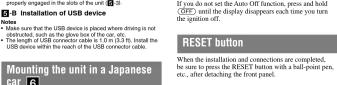
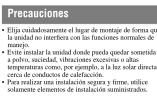
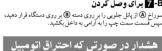
Precautions Choose the installation location carefully so that the unit will not interfere with normal driving operations. Avoid installing the unit in areas subject to least, diet, excessive ventilation, or high temperatures, such as in direct sunlight or near heater ducts. Use only the supplied mounting hardware for a safe and secure installation. Mounting angle adjustment Adjust the mounting angle to less than 45°. Notes • Install only with the supplied screws (T), or the front panel may not slide correctly. • Do not use holes not specific for the task, and do not install screws longer than 8 mm (1⁄2 ft). T: Toyota Cars. N: Nissan Carr