JK-84 Oasis - Overvågningskamera Joblotron - Gratis brugsanvisning og manual
Find enhedens vejledning gratis JK-84 Oasis Joblotron i PDF-format.

Brugerspørgsmål om JK-84 Oasis Joblotron
0 spørgsmål om dette apparat. Besvar dem du kender, eller stil dit eget.
Stil et nyt spørgsmål om dette apparat
Download vejledningen til din Overvågningskamera i PDF-format gratis! Find din vejledning JK-84 Oasis - Joblotron og tag din elektroniske enhed tilbage i hånden. På denne side er alle dokumenter nødvendige for brugen af din enhed offentliggjort. JK-84 Oasis af mærket Joblotron.
BRUGSANVISNING JK-84 Oasis Joblotron
The JK-84 “Oasis” wireless alarm kit
Installation of the JK-84 kit shall only be undertaken by technicians holding a certificate issued by an authorized distributor. This simplified installation manual only describes the basics, for more details see the manuals of particular devices.
- Factory-default pre-enrolled devices
| Address | Device Note | |
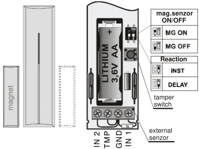
| 03 | JA-81M door detector | Delayed reaction |
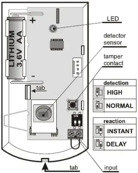
| 04 JA-80P | PIR detector Delayed | reaction |
| 48 | RC-86 keyfob | Buttons and pre-enrolled |
| 49 JA-80F | keypad unit | Connect a magnetic door sensor to its IN input. |
| 50 JA-80L | indoor siren | With an RC-89 wireless door-bell button pre-enrolled. |
| JA-82KR | Pre-enrolled to the JA-80L |
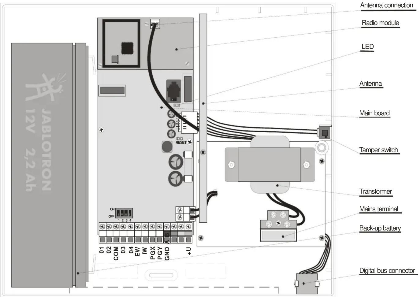
2. Control panel and keypad installation
- Attach the Control Panel (CP) to the desired location.
- Connect back-up battery to the CP (attach it securely with adhesive tape).
- Connect the mains to the CP – its green LED will start flashing
-
Connect up the batteries in the JA-80F keypad – service mode should be displayed (if not, disconnect the keypad batteries, check that the control panel is powered up and reconnect the keypad batteries).
-
Keeping the * key pressed while connecting the keypad batteries will open the keypad's internal menu which allows you to select the desired language (English = 1), to exit this menu press the # key.
○ If you exit Service mode accidentally, it can be re-entered by keying in * 0 8080. - Close the keypad's flip cover to save the battery while in the service mode.
Before attaching the JA-80F keypad, test that it functions correctly at the desired location. We recommended wiring up a magnetic door sensor (provided with the kit) to the keypad's IN input. This will ensure that the keypad is "woken up" whenever the door is opened (to indicate system status, to make entrance delay beeps and to have the access card reader ready for reading cards).
3. Installing the detectors and the siren
- Install the JA-81M magnetic detector, select its reaction via the internal DIP switch (INS/DEL), connect its battery up and close the cover.
- Install the JA-80P PIR motion detector about 2 to 2.5 meters above the floor, select its reaction via the relevant internal DIP switch (INS/DEL), connect its battery up and close the cover.
- Plug the JA-80L siren into a mains power socket.
4. Enrolling more wireless devices
The system can be extended with more wireless devices (a maximum of 50 can be enrolled). To enroll another device, the CP should be in service mode, if it is not enter * 0 8080 (while the system is unset).
- On the keypad, key in 1 to enter enrollment mode.
- The next vacant address is displayed (scroll to other addresses using the arrow keys if desired).
- Connect up the device's battery to enroll the device to the CP. Successful enrollment is confirmed by the A indicator lighting. The next vacant address is then displayed.
- The RC-86 key-fob can also be enrolled by pressing and holding a pair of its buttons 📄 + 📅 or + 🌐
4. Exit enrollment mode by pressing the # key.
- To enroll the CP to UC-82 or AC-82 modules, enter 299 while the CP is in service mode with the receiving module in enrollment mode.
5. Testing device functionality
- The CP should be in Service mode, if not enter * 0 8080
- First trigger the device under test (e.g. a detector). The keypad (with its flip cover open) then indicates triggering of the device if the device is functioning correctly and is enrolled.
- Motion detectors are best tested within 15 minutes of closing their covers as after that they only react to frequent movements once every 5 minutes (to restart a device's test mode, open and close the detector housing again).
6. Checking a device's radio signals
- The CP must have its antenna connected and should be in Service mode, if not enter * 0 8080
- Enter 298, the lowest address with enrolled device will be displayed.
- Trigger the device linked to this address – the keypad (with its flip cover open) then shows the device's signal strength in the range 14 to 4/4 (it should be at least 2/4, if not, relocate the device)
○ Motion detectors are best tested within 15 minutes of closing their covers as after that they only react to frequent movements once every 5 minutes (to restart a device's test mode, open and close the detector housing again).
To test the JA-80F keypad signal, trigger the connected magnetic door sensor or activate the keypad's tamper sensor. - To test the JA-80L siren signal, press the siren's button.
- To select the next enrolled device address use the arrow keys.
- To exit signal measurement mode, press the # key.
7. Programming the system
- The CP should be in Service mode, if not enter * 0 8080
- Enter the appropriate programming sequences to select the desired functions (a complete list of them is in the CP and communicator manuals).
| Function Sequence Note | ||
| New service code | 5 xxxxxxxxx | Factory default: 8080xxxx = new code |
| Exit delay 20x | x = multiples of 10 sec.(e.g. 205 = 50 sec)Factory default: 30 sec | |
| Entrance delay 21x | x = multiples of 5 sec.(e.g. 204 = 20 sec)Factory default: 20sec | |
| Alarm duration 22x | x = 1 to 8 means 1 to 8 minutes and 9 means 15min.Factory default: 4 min | |
| Time and date entry | 4 hh mm DD MM YY | |
8. Editing keypad text strings
- The CP should be in Service mode, if not enter * 0 8080
- Press and hold the ? key to enter editing mode.
- Keys: 1 & 7 scroll through characters and numbers,
4 & 5 move the cursor,
2 erases the highlighted character,
▲ & ▼ are for the selection of text strings,
exits editing mode.
Editing text only affects the text in that particular keypad. A more convenient way of text editing is with a PC running Olink software.
9. Finishing off the installation
- Exit service mode via the # key and demonstrate clearly how to operate the system to the user(s).
- Recommend the user to change the default master 1234 code to a new master code.
| Entry | Function |
| code / card | Setting/unsetting (arming and disarming) |
| ABC | Complete arming (all sections) |
| A | Partially setting A (if used) |
| B | Partially setting AB (if used) |
| *4 | Reading the event memory (4 scrolls backwards) |
| *5 | Changing the MASTER code/card (e.g. *5 1234 2789 2789) |
| *6 | To create a new user code/card (e.g. *6 1234 03 3344 programs user code number 3, to erase the code enter: *6 1234 03 0000) |
| *7 code/card | To secretly signal operation (unsetting) under duress |
| *8 a *9 | PGX and PGY control (if used) |
| *0 MASTER code | Maintenance mode (testing, overview of codes, bypassing,...) |
| # | Exiting maintenance mode or terminating an incomplete entry |
| ? | Displays status details (triggered detectors, fault causes or the status of PG outputs .....) |