UC-242 - Overvågningskamera Joblotron - Gratis brugsanvisning og manual
Find enhedens vejledning gratis UC-242 Joblotron i PDF-format.

Brugerspørgsmål om UC-242 Joblotron
0 spørgsmål om dette apparat. Besvar dem du kender, eller stil dit eget.
Stil et nyt spørgsmål om dette apparat
Download vejledningen til din Overvågningskamera i PDF-format gratis! Find din vejledning UC-242 - Joblotron og tag din elektroniske enhed tilbage i hånden. På denne side er alle dokumenter nødvendige for brugen af din enhed offentliggjort. UC-242 af mærket Joblotron.
BRUGSANVISNING UC-242 Joblotron
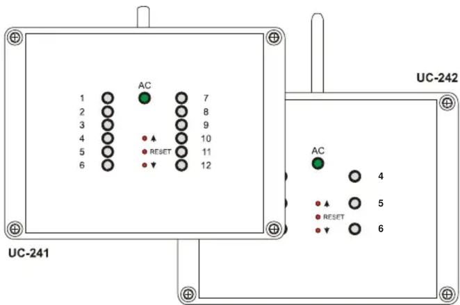
The UC-241 is a 12-channel receiver of signals from TP wireless thermostats or from JA-60 wireless detectors. The UC-242 is a six-channel receiver. The two receivers have 12 and 6 outputs respectively, which can be used to control various devices. LEDs on the receiver's front cover indicate the status of each output channel. Additionally, a power relay is used for a pump control (the relay is on if any output is triggered).
When used with wireless thermostats, the UC-241 / UC-242 can efficiently control multi-zone heating and cooling systems.
JA-60M wireless detectors can also be used to control the UC-241's or UC-242's output relays remotely from any switching device (switch, micro switch sensor etc.). This can be convenient for automation or control tasks.
The receivers can also receive signals from JA-60S wireless smoke sensors and JA-60G gas leak sensors.
Specification
Power supply: 24 V AC
Stand by consumption: 0.05 A
Max. supply current: 2 A
Internal current protection: fuse F 3.15 A
Max. output load: max. 2 A per one output and 2 A
totally for all 1-12 outputs
Receiver radio frequency: 433.9 MHz, ISM EN 300220
Working distance: max.100 m in an open area
Dimensions: 165 x 125 x 75 mm (w/o antenna)
EMC EN
Working environment: IP20 EN 60529
Humidity: max. 85 %
Working temperature): -10 to +40 °C
300683
Hereby, Jablotron Ltd., declares that this UC-241 and UC-242 is in compliance with the essential requirements and other relevant provisions of Directive 1999/5/EC. Original of the conformity assessment can be found at the web page www.jablotron.cz, section Technical support.
Installation
- Remove the 4 screws holding the front cover and open the housing. Unplug the internal cable and remove the cover.
- Attach the UC-241/242 in the desired location with two screws (provided).
- Route cables through the housing and connect them to the terminals (see terminal description and examples of wiring).
- Plug in the front panel cable and reattach the front cover to the housing.
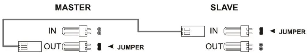
Note: Do not locate any cable close to the receiver antenna and do not install any other UC-241/242 closer than 2 meters (this could shorten the working distance). If you need a receiver with additional channels, you can connect two or more receivers with a two-wire data cable. The jumper setting indicates the master receiver (see Fig.4)!
Terminals description:
AC, AC – AC power input 24 V AC
L-A, N-A. PE-A - power supply input for the circulatory pump (use external fuse for its protection)
L-B, N-B. PE-B - terminals for the circulatory pump connection (the L-B terminal is triggered if any of the 1-12 outputs are switched)
1- 12 – transistor outputs (switch to ground)
COM – common positive output terminals
Indicators
Green LED AC indicates the presence of the receiver's power supply. When lit, the receiver is powered.
Indicators 1 to 12 indicate the status of the output channels (relays).
| LED 1 - 12 | Description |
| Off | Channel is not used (no transmitter is enrolled) |
| Steady Green | Channel has a transmitter enrolled, relay is off |
| Steady Red | Relay is on (activated by the enrolled transmitter) |
| Flashing Green | Communication with the enrolled transmitter is down (Low battery in transmitter, radio interference etc.) |
| Flashing Red | Learning mode (to enroll a transmitter) |
Enrollment of transmitters
For each channel of the receiver, a transmitter (thermostat or wireless detector) can be enrolled in the following way:
- Press and hold ▲ or ▼ (UP or down) button in order to select the desired channel (current channel will be indicated by its LED flashing)
- insert batteries to the transmitter (thermostat or detector). When powered, the transmitter generates an enrollment signal and its code is stored in the selected receiver channel's memory
- enrollment of the transmitter is confirmed by the constant lighting of the green LED.
Only one transmitter can be enrolled to each UC-241 / UC-242 channel. A transmitter can be enrolled to multiple receivers without any restrictions. If you try to enroll a new transmitter to an occupied channel, the new transmitter will be stored and the former one will be erased.
Erasing of a transmitter
To erase an existing transmitter,:
- using button or (UP or down) select the desired channel (current channel will be indicated by its LED flashing)
- press the RESET button and the corresponding LED will turn off
Use and Maintenance
All enrolled transmitters (thermostats and detectors) transmit regular checking signals. If the receiver does not receive the signal of an enrolled transmitter for a certain period, it will indicate that communication with this item is down (flashing green LED) and the corresponding relay will turn off.
A reason for the lost connection can be low batteries in the transmitter. Average lifetime of the transmitter's batteries is about 1 year. Each transmitter checks its battery's conditions and signals in advance if the batteries are reaching a critically low state (see the transmitter manual for details).
Another reason of possible connection failure can be from radio signal interference in the working band of the receiver. In such a case the UC-241 /UC-242 will usually indicate loss of communication with a multiple number of transmitters. In this situation, check if there is any non-approved radio-communicating device in the working range of the receiver.
Warning: manufacturer is not responsible for any damage caused by improper installation or non-suitable use of this product.
Note: Although this product does not contain any harmful materials we suggest you to return the product to the dealer or directly to the producer after usage

JABLOTRON
Pod Skalkou 33
466 01 Jablonec nad Nisou
Czech Republic
Tel.: +420 483 559 999
fax: +420 483 559 993
Internet: www.jablotron.cz
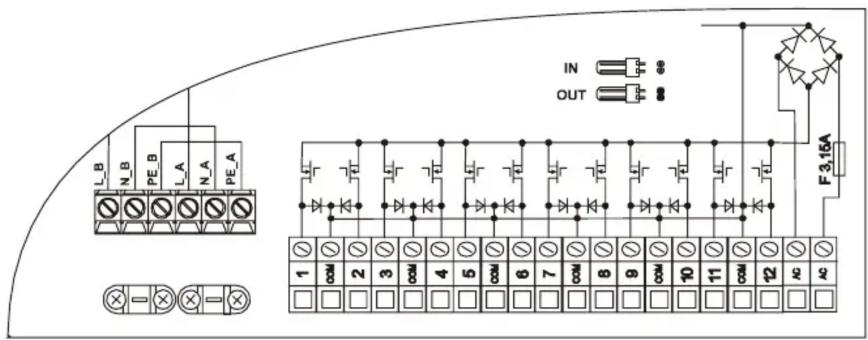
Fig.1 UC-241 terminals
Fig.2 UC-242 terminals

Fig. 3 Sample of UC-241 wiring
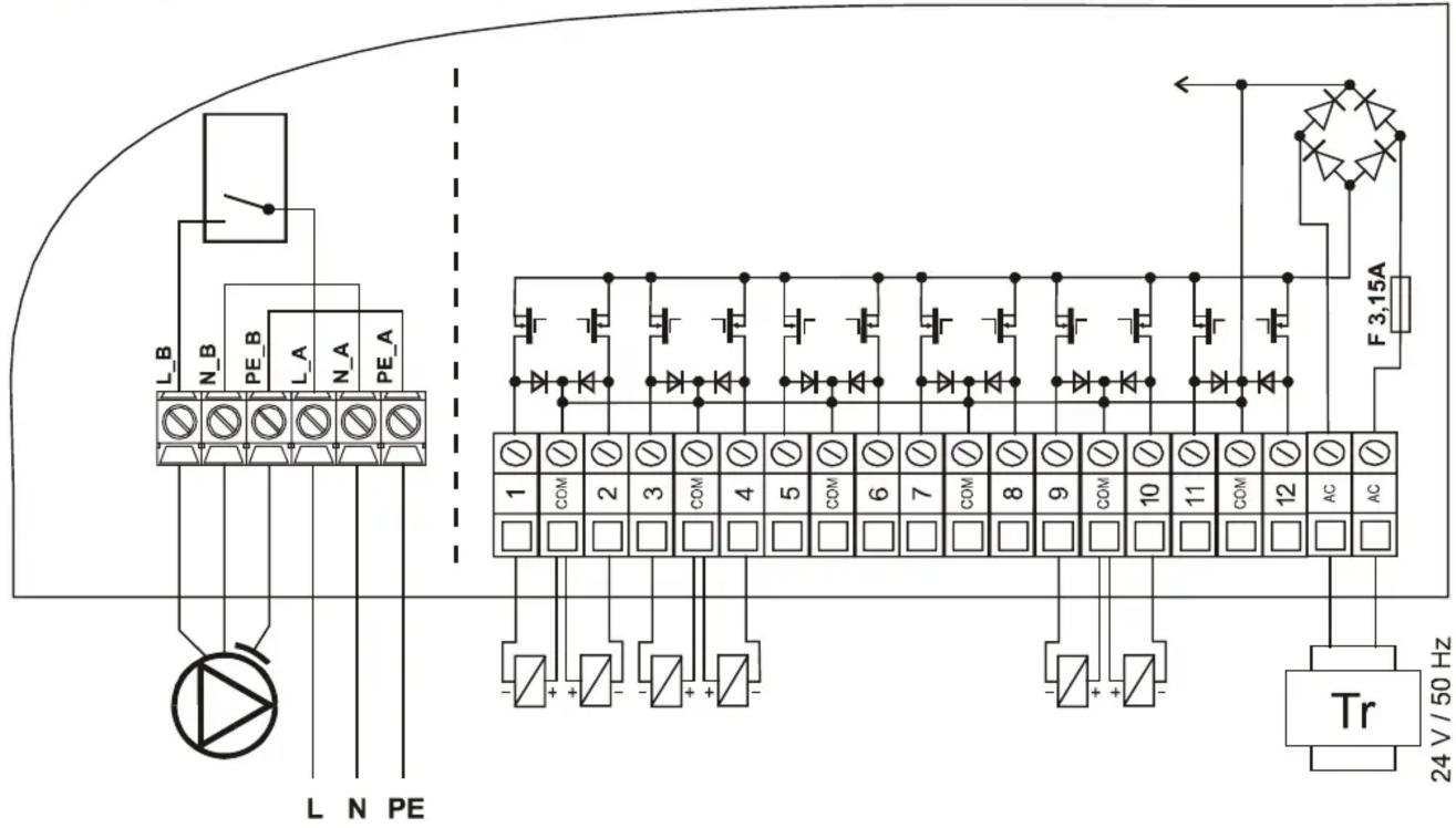
Fig.4 Connecting more receivers together
flowchart
graph LR
    A["MASTER"] --> B["IN"]
    A --> C["OUT"]
    A --> D["JUMPER"]
    E["SLAVE"] --> F["IN"]
    E --> G["OUT"]
    E --> H["JUMPER"]