TP-31 - Overvågningskamera Joblotron - Gratis brugsanvisning og manual
Find enhedens vejledning gratis TP-31 Joblotron i PDF-format.

Brugerspørgsmål om TP-31 Joblotron
0 spørgsmål om dette apparat. Besvar dem du kender, eller stil dit eget.
Stil et nyt spørgsmål om dette apparat
Download vejledningen til din Overvågningskamera i PDF-format gratis! Find din vejledning TP-31 - Joblotron og tag din elektroniske enhed tilbage i hånden. På denne side er alle dokumenter nødvendige for brugen af din enhed offentliggjort. TP-31 af mærket Joblotron.
BRUGSANVISNING TP-31 Joblotron
The TP-31 wireless thermostat
This thermostat can replace a common indoor residential thermostat. It can be used with receivers produced by Jablotron such as the UC-222, UC-6007, UC-6014 etc.). It is designed to be used with electrical, gas or oil heating systems. The temperature adjustment can be done very simply by turning a setting knob. The main advantage is that there is no need for a cable between the thermostat and the heating system.
Installation
The TP-31 should be mounted in a dry indoor location. Choose a mounting location about 1.5 meters above the floor in an area with good air circulation. Avoid places with draughts, dead air spots and radiant heat from the sun or appliances. It should not be installed close to any metal structure or other objects that may obstruct radio signal transmissions
- Remove the front housing of the thermostat by gently pressing the tab on the right side (using a screwdriver).
- Attach the thermostat to desired position on the wall with the two screws.
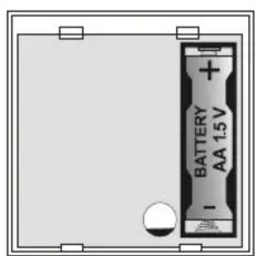
- Insert the battery.
- Close the thermostat.
Mounting the UC-222 receiver unit
Note: only a qualified technician should provide installation and servicing.
Place the receiver unit in a suitable place near the heater. Wiring the unit to the heater should only be done by a professional electrician.
- Release the upper cover by pressing the plastic tab on the top side of housing.
- Release the internal cover (1 screw).
- Mount the unit to the desired location (2 screws).
- Connect power 230VAC/50Hz to terminals L and N.
- Two PE terminals are available for a protective earth connection.
- Terminals C (common), N.O. (normally open) and N.C. (normally closed) are outputs of the relay contact. This contact is protected by a 6.3 separated.
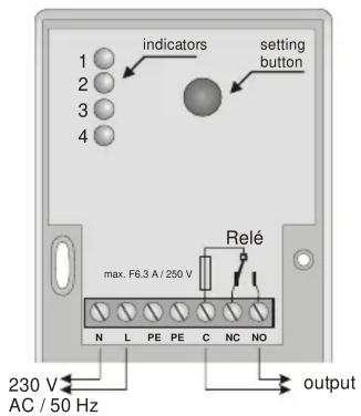
Note: A built-in LED indicator indicates the status of the output relay
Temperature setting
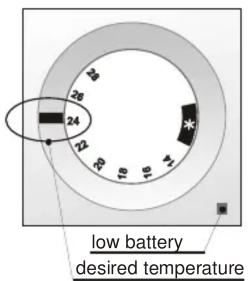
The desired temperature can be set simply by turning a knob placed on the top of the thermostat. If the set temperature is higher then actual temperature in the room the red indicator on the thermostat will lit for 3 seconds after turning the knob.
If it is set to * (anti-freezing mode), the thermostat will keep the temperature at 6 ^±0.5 ^ .
The information to the receiver unit is sent in about 5 seconds after setting the desired temperature. The LED on the receiver unit indicates heating.
Low battery
If the yellow low-battery indicator on the lower right corner of thermostat is flashing, replace the battery.
Enrolling the thermostat to the receiver unit
The thermostat can be enrolled to the receiver unit in the following way:
- Remove the battery from the thermostat for 1 minute.
TP-31 wireless thermostat - 1 - MJF51006
- Remove the upper housing from the receiver unit.
- Keep pressing the button inside the receiver until the 4th LED starts flashing.
- Insert the battery into the thermostat. The LEDs in the receiver will flash once to confirm enrollment.
Note:
If the thermostat is delivered as a kit with the UC-222 receiver (TP-31 SET), then it has already been pre-enrolled to the receiver unit in the factory, so it is not necessary to enroll it again.
Each receiver unit can work with up to 8 thermostats. If any other device (remote control etc.) has been enrolled to the receiver, the receiver must be reset before enrollment of the thermostat. To reset the memory, make the 4th LED flash by pressing the button, and then press and hold the button until all LEDs flash rapidly.
natural_image
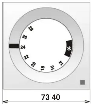
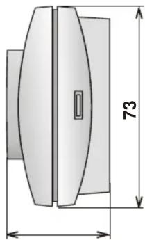
Technical drawing of a mechanical component with dimension标注 (73), no readable text or symbols present.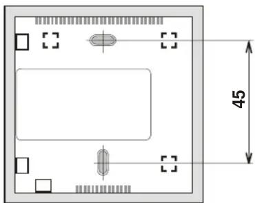
natural_image
Top-down schematic of a rectangular device with internal components and dimension标注 (no text or symbols)Specification
Thermostat TP-31
| Power supply: | 1x AA 1.5 V alkaline battery |
| Temperature Accuracy: | ± 0.5 °C |
| Temperature Measurement: | 6 °C and 14 - 28°C |
| Working frequency: | 433.92 MHz |
| Coding: | Digital, each thermostat has a unique floating code |
| Working distance | up to 100 m (open area) |
| Working temperature: | -10 °C to + 50 °C |
| Dimension: | 73 x 40 x 73 mm |
Receiver unit UC-222
| Power supply: | 230 V AC 50 Hz, protection class II |
| Power drain: | 1 VA (0.6 W) standby 1.8 VA (1 W) relay switched on |
| Frequency: | 433.92 MHz |
| Coding: | digital, each thermostat has a unique floating code |
Output relay: over switching dry contact, fused 6 A at 250 V Can be operated according to ERC REC 70-03
CE Jablotron Ltd. hereby declares that the TP-31 is in compliance with the essential requirements and other relevant provisions of Directive 1999/5/EC.
Original of the conformity assessment can be found at the web page www.jablotron.com, section Technical support.
Note: Dispose of batteries safely depending on the type of the batteries and local regulations. Although this product does not contain any harmful materials we suggest you return the product to the dealer or directly to the manufacturer after use.

Pod Skalkou 33
466 01 Jablonec nad Nisou
tel.: 483 559 999
fax: 483 559 993
Internet: www.jablotron.com