UC-280 - Overvågningskamera Joblotron - Gratis brugsanvisning og manual
Find enhedens vejledning gratis UC-280 Joblotron i PDF-format.

Brugerspørgsmål om UC-280 Joblotron
0 spørgsmål om dette apparat. Besvar dem du kender, eller stil dit eget.
Stil et nyt spørgsmål om dette apparat
Download vejledningen til din Overvågningskamera i PDF-format gratis! Find din vejledning UC-280 - Joblotron og tag din elektroniske enhed tilbage i hånden. På denne side er alle dokumenter nødvendige for brugen af din enhed offentliggjort. UC-280 af mærket Joblotron.
BRUGSANVISNING UC-280 Joblotron
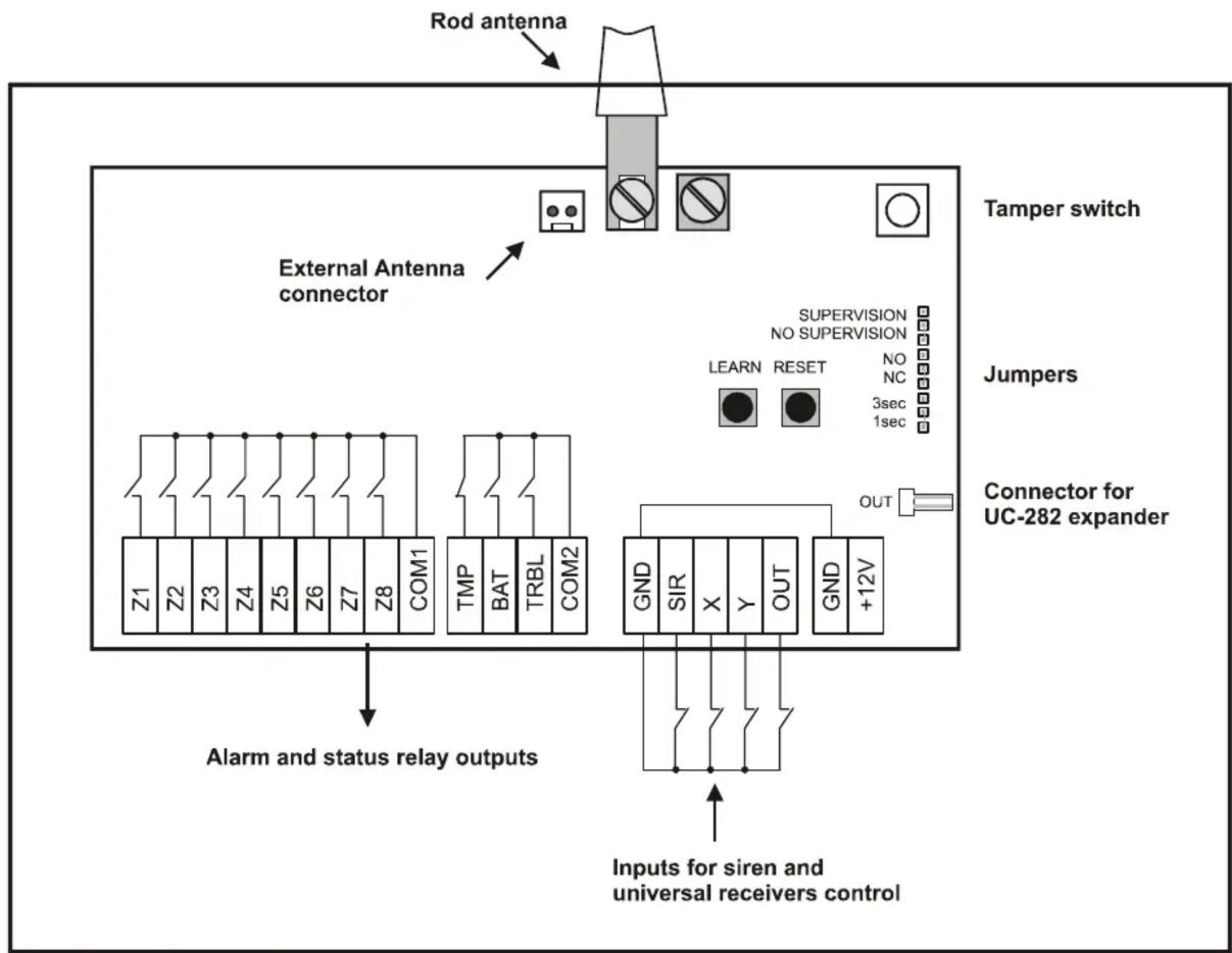
UC-280 Wireless Interface
The UC-280 is an 8-zone interface linking JA-60 wireless detectors with hard-wired security control panels. It can also send triggering signals to a JA-60A wireless outdoor siren and/or UC-216 and UC-222 universal receivers. Additionally, it can receive signals from Jablotron RC-xx remote controls. If necessary, UC-282 expander modules can be used to increase the number of zones up to 40.
Specification
Power 12 V DC (10.5 V - 16.0 V)
Power consumption typ. 50 mA (all relays off)
max.
Zone outputs Z1-Z8 8x optoMOS relays 100 mA / 60 V
with COM1 common terminal
Outputs 3x optoMOS relays 100 mA / 60 V
Tamper NC with COM2 common terminal
Fault, Battery NO with COM2 common terminal
X, Y and Siren inputs activated
when switched to GND (filter 0.2
sec., 1 V DC triggering level)
Operating frequency 433.9 MHz
Working range with JA-60 100 m (open area)
Working range with RC 30 m (open area)
Working environment indoor use (class II, EN 50131-1)
Operating temperatures -10 °C to +70 °C
max. 90 %
Dimensions 188 x 135 x 40 mm
Weight

Hereby, Jablotron Ltd., declares that this UC-280 is in compliance with the essential requirements and other relevant provisions of Directive 1999/5/EC. Original of the conformity assessment can be found at the web page www.jablotron.cz, section Technical support.
Note: Although this product does not contain any harmful materials we suggest you to return the product to the dealer or directly to the producer after usage.
Purchase package contains: electronic board, metal case, antenna, screws, dowels, and manual.
Installation
The UC-280 is an electronic module built-in to a metal case (protected by a tamper switch). The case should be installed on a wall with its antenna in a vertical position. The device should not be installed close to any metal structures or other objects obstructing radio signal transmission.
Route the wires through the hole in the rear part of the housing. Attach the case to the desired place using the provided screws. Connect the antenna.
100
mA
Terminals:
| Z1-Z8 | Zone 1-8 output relays' contacts, max. 100 mA / 60 V, pulse length can be set by 1s/3s jumper, normally closed or normally opened mode is selected by the NO/NC jumper |
| COM1 | common terminal of Z1-Z8 relays |
| TMP | tamper relay output (tamper signal from wireless detectors, a wireless siren and the UC-280 tamper switch), max. 100 mA / 60 V |
| BAT | low battery relay output (low battery signal from wireless detectors 1-8 or a wireless siren), max. 100 mA / 60 V |
| TRB | trouble relay output (trouble signal from wireless detectors 1-8 or a wireless siren - e.g. lost communication), max. 100 mA / 60 V |
| COM2 | common terminal of TMP, BAT and TRB relays |
| GND | power supply ground terminal |
| SIR | triggering input for activation of JA-60A wireless siren (the siren sounds as long as this input is closed to GND, max. 15 minutes) |
| X | input, which can trigger relay X of a UC-216 or UC-222 universal receiver when switched to GND |
| Y | input, which can trigger relay Y of a UC-216 universal receiver when switched to GND |
| OUT | input, which can trigger output OUT of a UC-216 universal receiver when switched to GND |
| +12V | power voltage terminal |
flowchart
graph TD
    A["Rod antenna"] --> B["Tamper switch"]
    B --> C["External Antenna connector"]
    C --> D["Connector for UC-282 expander"]
    D --> E["Alarm and status relay outputs"]
    E --> F["Inputs for siren and universal receivers control"]
    style A fill:#f9f,stroke:#333
    style B fill:#ccf,stroke:#333
    style C fill:#cfc,stroke:#333
    style D fill:#fcc,stroke:#333
    style E fill:#cff,stroke:#333
    style F fill:#ffc,stroke:#333
Connectors:
OUT data connector for UC-282 expander module
ANT AN-01A external antenna connector (when AN-01A is used, the rod antenna must be disconnected)
Setting buttons:
LEARN if this button is briefly pressed, you can scroll through the learning modes of Z1-Z8 zones and a wireless siren SIR (a selected channel is indicated by a red flashing LED). When this button is pressed for more than 3 sec., the enrolling signal for a UC-216 / UC-222 receiver will be transmitted (learning mode of Z1-Z8 and SIR must be closed first)
RESET if this button is briefly pressed, the learning mode of a selected zone will be closed. When this button is pressed for more than 3 sec., a selected zone will be deleted (confirmed by flashing of the TMP, BAT and TRB indicators). When this button is pressed for more than 6 sec., all zones will be deleted (confirmed by flashing of all indicators). Note, in order to delete all zones, a learning mode of any zone must be selected first.
Jumpers:
1s / 3s pulse length of 1 sec. or 3 sec. of Z1-Z8 output relays
NO / NC normally closed or normally opened mode of Z1-Z8 output relays (TMP, BAT and TRB are normally closed)
Supervision - Regular checking of wireless detectors' communication can be disabled (NO SUPERVISION position). This setting is recommended in places with radio interferences. When the supervision is enabled, lost communication will trigger the TRB output relay.
Indicators:
POWER The green LED indicates the presence of the power supply
Z1 - Z8, LED lights green when zone is occupied;
SUE D lights red when zone detector is triggered;
LED flashes red, when zone is in a learning mode;
LED flashes red together with the TMP, BAT or TRB LED = tamper, low battery or trouble signal in zone
TMP tamper alarm – flashes together with a corresponding zone indicator every 3 sec.
BAT low battery - flashes together with a corresponding zone indicator every 3 sec.
TRB trouble or lost communication - flashes together with a corresponding zone or SIR indicator every 3 sec.
Enrolling of wireless components
Enrolling of detectors
- Scroll to a desired zone Z1-Z8 using the LEARN button
- JA-60 detectors will be enrolled by inserting their batteries or switching on a power supply
- Successful learning is indicated by the red LED
- If you enroll a component to a new zone, it will move from its previous position
- Only one detector can be enrolled to each zone
Enrolling of remote controls
- Scroll to a desired zone Z1-Z8 using the LEARN button
- RC-xx remote controls will be enrolled by pressing a button (while in pulse mode). Button A, B or double press can be enrolled.
- RC-11 or RC-22 Remote controls can be enrolled to any zone in an ON/OFF mode by pressing both buttons and keeping them pressed for more than 5 sec. After this the corresponding relay will switch on when the A button is pressed, and off, when the B button is pressed.
- If a combination of double press and ON/OFF mode is required, the ON/OFF mode must be enrolled first.
- Successful learning is indicated by the red LED
- If you enroll a remote control to a new zone, it will move from its previous position
- Only one remote control can be enrolled to each zone
Enrolling of a wireless siren
- Connect a battery in a JA-60A siren and power its adapter
- Select the SIR position with the LEARN button
- When the SIR position is selected, the UC-280 will send a learning signal to the JA-60A and vice versa. Triggering the SIR input will then activate a JA-60A, tamper alarm or power supply failure of the JA-60A will be transmitted to a UC-280
- Only one JA-60A siren can be used with a UC-280
Enrolling of UC-216 or UC-222 modules
- Select the learning mode in a receiver (mode X1 for UC-216 or mode 4 for UC-222)
- Learning mode of UC-280 must be closed
- Press and hold the LEARN button in UC-280 for 3 seconds
- The UC-280 will now be enrolled to the UC-216 or UC-222 receivers and triggering of X and Y inputs will trigger the UC-216 / UC-222 output relays.
- Unlimited number of UC-216 / UC-222 can be used with a UC-280
Erasing components
If you want to delete any item from a UC-280, use the RESET button (the procedure is described in "Setting buttons" paragraph).
Extension for more zones
When 8 zones are not enough, you can use UC-282 expander modules. Each UC-282 module provides additional 8 zones. A maximum of 4 expanders can be used with UC-280. Modules are interconnected using the IN and OUT connectors, wiring should not exceed 1 meter. Each UC-282 must be powered by 12 V DC separately.