AC-8014 - Overvågningskamera Joblotron - Gratis brugsanvisning og manual
Find enhedens vejledning gratis AC-8014 Joblotron i PDF-format.

Brugerspørgsmål om AC-8014 Joblotron
0 spørgsmål om dette apparat. Besvar dem du kender, eller stil dit eget.
Stil et nyt spørgsmål om dette apparat
Download vejledningen til din Overvågningskamera i PDF-format gratis! Find din vejledning AC-8014 - Joblotron og tag din elektroniske enhed tilbage i hånden. På denne side er alle dokumenter nødvendige for brugen af din enhed offentliggjort. AC-8014 af mærket Joblotron.
BRUGSANVISNING AC-8014 Joblotron
The AC-8014/814 receiver
The AC-8014 is a 14-channel receiver of signals from TP-8x wireless thermostats working on a frequency of 868 MHz. It can also be used with TP-8x digital bus thermostats. The AC-8014 can efficiently control multi-zone heating (including thermoelectric actuating valve-drivers to replace thermostats on radiators) or cooling systems. The receiver has a special MODE channel which turns the heating to economy mode. It is designed for heating system control and is not suitable for extending hardwired alarm systems via wireless detectors.
Due to the maximum current limits of the outputs, pulses switching the outputs off for short moments are used (when more then 8 outputs are used). Therefore the AC-8014 should only be used with thermoelectric actuating valve-drivers. It should not be used to control any relays, semiconductor switches etc. LEDs on the receiver's front cover indicate the status of each output channel.
The AC-8014 can be considered a hybrid of two components: the AC-814 digital bus receiver and the wireless module. The AC-814 only allows connection by digital bus and can be supplied standalone as a cut-down variant of the AC-8014.
The AC-8000R built-in power relay module can be used as a pump control. A second AC-8000R module can be plugged-in to provide boiler control. Both relays work with OR logic: they are switched if any of the 1–14 outputs is activated.
Installation
Attach the unit to the desired location with three screws. Route all the cables to the unit before you tighten the case.
Fix the cables firmly inside the box by a sliding strap.
Note: Only a qualified technician should provide installation and servicing. The user is not allowed to open the cover and/or make any modifications. The mains cable must also be fixed outside the receiver's case. Replace the mains plug if necessary for your country.
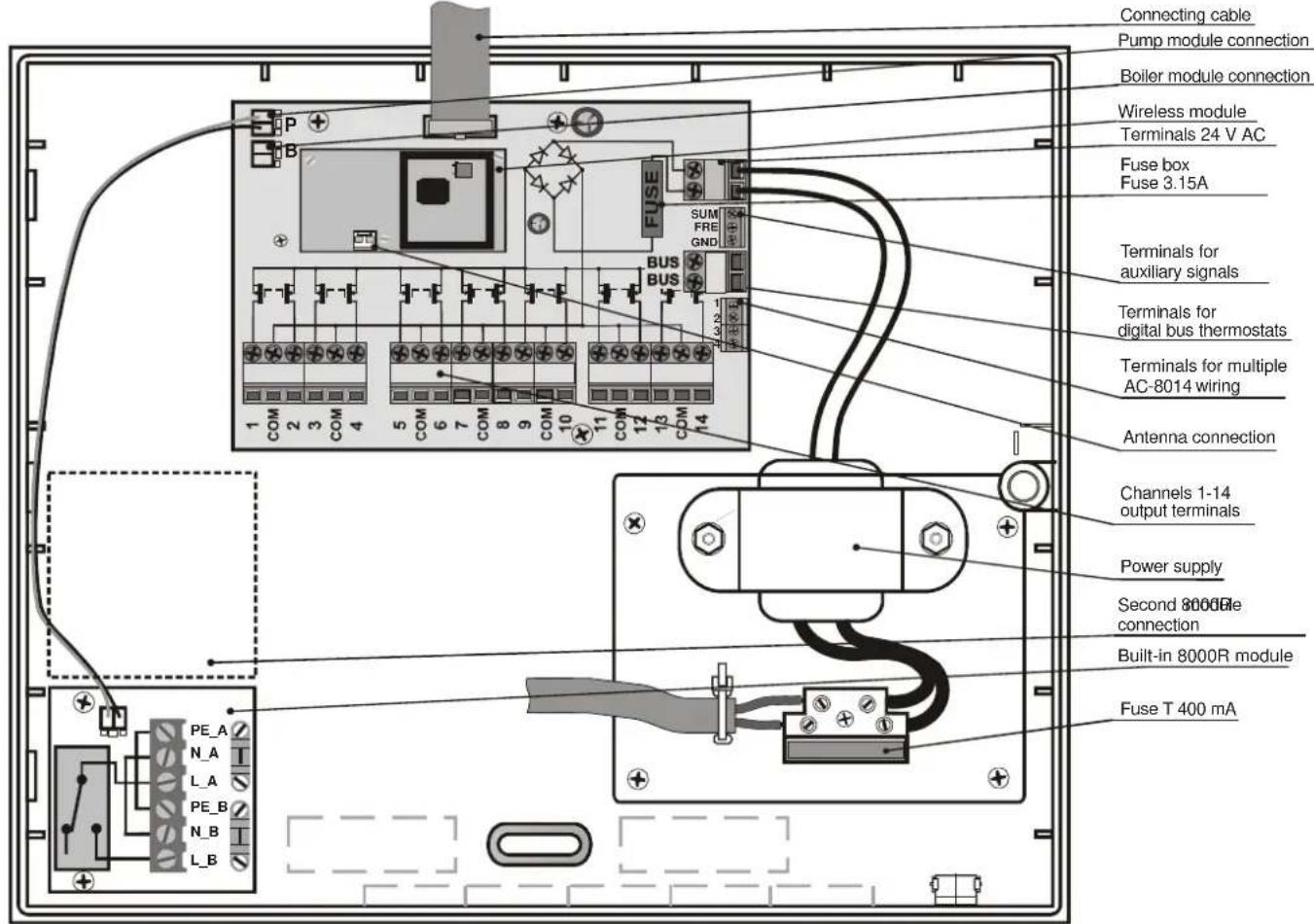
Terminal description:
AC, AC - power input 24 V AC.
SUM (summer) – input terminal. When switched to ground, economy mode is activated. This is indicated by the MODE channel LED lighting.
FRE (freeze) - output terminal. If any of the thermostats sends a signal about the temperature being under the value of the ALLo (critically low temperature) parameter in the thermostat, this terminal switches to ground for 10 seconds. The terminal's maximum load is 100mA .
BUS,BUS – terminals for the digital bus connection (for thermostats of the relevant type). Maximum length of the connection cable is 200m.
1-14 - channel outputs, switchable to ground. The AC-8014 has pulsed switching.
COM – common positive output terminals 24V DC.
Terminals of the AC-8000R power module:
L_A, N_A, PE_A – power supply input for the circulatory pump or boiler (use an external fuse for its protection).
L_B, N_B, PE_B - terminals for the circulatory pump or boiler connection (the L_B terminal is triggered if any of the 1-14 outputs are switched on).
The receiver is protected against shorts on the output. If the output is overloaded (the current is greater than 0.4A), then the output is automatically disconnected. A fault is indicated by rapid red flashing of the corresponding LED indicator. The output is under constant monitoring and when the output current decreases below 0.4A the output will be switched on again.
If it is necessary to have more channels, then it is possible to connect another unit via a 4-wire cable connected to terminals 1–4. In this case a single wireless unit should be shared by both receivers. However, each receiver only controls its own built-in AC-8000R module.
There is an available connector for an external antenna (e.g. AN-80 or AN-81) on the bottom side of the front housing. If the external antenna is used no further modifications to settings or connections are necessary.
Enrollment of thermostats
For each channel of the receiver, a thermostat can be enrolled in the following way:
- Repeatedly press button < or > (left, right arrow) to select the desired channel (the current channel will be indicated by its LED flashing).
- Insert batteries into the thermostat. When powered up, the thermostat generates an enrollment signal and its code is stored in the selected receiver channel's memory.
- Digital bus thermostats can be enrolled by pressing and holding their button for 5 seconds.
- Enrollment of a thermostat is confirmed by the constant lighting of the green LED.
Only one thermostat can be enrolled to each channel. A thermostat can be enrolled to multiple channels or other receivers without any restrictions (it allows the control of several zones by one thermostat). If you try to enroll a new thermostat to an occupied channel, the new thermostat will be stored and the former one will be deleted.
Note: Enrollment codes are stored in non-volatile memory, so power disconnection will not erase them.
Deleting a thermostat
To delete an existing thermostat:
- Using buttons < and > select the desired channel (the current channel will be indicated by its LED flashing)
- Press the RES button, the corresponding LED will turn off and the thermostat is deleted.
Indicators 1–14
Indicators on the front housing of the receiver indicate the status of the output channels.
| 1 | 2 | 3 | 4 | 5 | 6 | 7 |
| CHANNEL |
| LEDs 1 to 14 Meaning | |
| Off Channel is not used (no thermostat is enrolled) | |
| Steady Green Channel has a thermostat enrolled, relay is off | |
| Steady Red Relay is on (activated by the enrolled thermostat) | |
| Flashing Green | Communication with the enrolled thermostat is down (Low battery in thermostat, radio interference etc.) |
| Flashing Red Enrollment mode (to enroll a thermostat) | |
| Flashing Red (rapidly) | Output is overloaded or short-circuited. |
Using the MODE channel / SUM input
The receiver has a special MODE channel to which a JA-8x control panel (PgX output) or RC-8x remote controls can be enrolled as well as detectors of type JA-80M. The SUM terminal has the same function for wired control. This channel can be used for remotely controlling the mode in which all the outputs will work, switching between two possibilities: 1) The outputs may be controlled by thermostat signals demanding/stopping heating 2) The outputs are disabled, but will respond to freezing alert signals demanding heating. The status of this channel is shown by the MODE indicator.
Repeatedly press button < or > (left, right arrow) to select the MODE channel (the current channel will be indicated by its LED flashing, in this case aim for the MODE LED) and transmit the enrollment signal. Enrollment of the transmitter is confirmed by the constant lighting of the green MODE LED.
If no transmitter is enrolled to the MODE channel, then outputs 1-14 react in a normal way to signals from their corresponding thermostats.
If a control panel is enrolled and the PgX output is activated (MODE indicator lit red) outputs 1–14 react in a normal way to signals from their corresponding thermostats.
If the PgX output is deactivated (MODE indicator lit green), then outputs 1–14 are deactivated. They can only be activated in response to economy temperature signals from a TP-8x thermostat.
MODE indicator
| Off | The MODE channel is not used – no transmitter is enrolled (receiver reacts to standard signals from thermostats) |
| Steady Green | A transmitter is enrolled – the MODE channel is deactivated, (SUM is active)Outputs 1–14 only react to the economy temperature signals from thermostats |
| Steady Red | A transmitter is enrolled – the MODE channel is activatedOutputs 1–14 react to standard signals from thermostats |
| Flashing Green | Communication with the enrolled transmitter is down (Low battery in transmitter, radio interference etc.) |
Use and maintenance
All enrolled transmitters (thermostats and detectors) transmit regular check signals. If the receiver does not receive the signal of an enrolled transmitter for a certain period, it will indicate that communication with this device is down (flashing green LED) and the corresponding output will turn the heating on for 5 minutes every single hour.
One reason for the lost connection can be low batteries in the transmitter. The average lifetime of a thermostat's batteries is about 1 year (JA-8x detectors 3 years). Each transmitter checks its battery conditions and signals in advance if the batteries are reaching a critically low state (see the transmitter manual for details).
Another reason for possible connection failure can be radio signal interference in the operational band of the receiver. In such a case the receiver will usually indicate loss of communication with a multiple number of transmitters. In this situation, check if there is any non-approved or faulty radio-communicating device within the range of the receiver.
If outputs 1–14 have not been activated for 7 days they will switch on for 5 minutes to protect connected devices. This is also valid for the output relay provided by the built-in AC-8000R module thus providing protection for pumps which can be damaged if they are not used for a long time. However, this feature is disabled for the boiler connection established by an additional AC-8000R module.
Warning: the manufacturer is not responsible for any damage caused by improper installation or any non-suitable use of this product.
Specifications
| Power supply: | 230 V AC, 50Hz, protection class II |
| Consumption: | 0.02 A stand-by; 0.2 A max. |
| Max. power supply load | 1.7A |
| Internal load-protection | safety fuse F 3.15 A |
| Max. relay output load: | 10 A / 230V |
| Voltage of outputs 1–14 and COM: | 24V DC |
| Max. load of outputs 1–14: | max. 0.4 A per single outputand 1.7A total for all outputs |
| Radio frequency: | 868 MHz |
| Communication range | 100 m (open area) |
| Dimensions: | 258 x 214 x 77 mm |
| Mechanical resistance: | IK08 according to EN 50102 |
| Radio characteristics: | ETSI EN 300220 |
| EMC: | EN 50130-4, EN 55022 |
| Safety: | EN 60950 |
| Enclosure: | IP30 (EN 60529) |
| Operational temperature: | -10 to +40 °C |
| Can be operated according to ERC REC 70-03 | |

JABLOTRON ALARMS a.s. hereby declares that the AC-8014/AC-814 is in compliance with the essential requirements and other relevant provisions of Directive 1999/5/EC. The original of the conformity assessment can be found on the web site www.jablotron.com, Technical Support section.

Note: Although this product does not contain any harmful materials we suggest you return the product to the dealer or directly to the manufacturer after use.

JABLOTRON ALARMS a.s., Pod Skalkou 33 466 01 Jablonec nad Nisou Czech Republic Tel.: +420 483 559 911 fax: +420 483 559 993 Internet: www.jablotron.com