AC-83 - Overvågningskamera Joblotron - Gratis brugsanvisning og manual
Find enhedens vejledning gratis AC-83 Joblotron i PDF-format.

Brugerspørgsmål om AC-83 Joblotron
0 spørgsmål om dette apparat. Besvar dem du kender, eller stil dit eget.
Stil et nyt spørgsmål om dette apparat
Download vejledningen til din Overvågningskamera i PDF-format gratis! Find din vejledning AC-83 - Joblotron og tag din elektroniske enhed tilbage i hånden. På denne side er alle dokumenter nødvendige for brugen af din enhed offentliggjort. AC-83 af mærket Joblotron.
BRUGSANVISNING AC-83 Joblotron
The AC-83 wireless relay output module
The AC-83 is a component of Jablotron's Oasis system. It provides 3 relays which can be controlled by radio signals. The AC-83 is mains-powered. The device is suitable for heating control via signals received from wireless thermostats of the TP-8x series. You can use the device in the following combinations:
With PGX and PGY outputs of a JA-8x control panel equipped with a radio module (for switching between heating modes).
- With RC-8x remote controls (for switching between heating modes).
- With JA-80M or JA-82M magnetic door-detectors (for heating enablement or disablement).
Installation

Installation of this module shall only be undertaken by technicians holding a certificate issued by an authorized distributor.
Warning: this device is galvanically connected to the mains.
Open the module's cover (1 screw) and take out the circuit board (2 tabs). Install the back part of the housing to the desired place, re-install the circuit board, connect the wires and enroll the desired wireless devices.
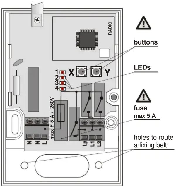
Terminals
L, N, N Power 230V/50Hz (N, N is a pair of connected terminals)
Lp Normally open contact for the Z common relay
L1 Normally open contact for the X output relay
L2 Normally open contact for the Y output relay
All normally open contacts are fused by a common 5 Amp fuse – the total combined consumption of the terminals must not exceed this limit.

Warning: The mains power output does not provide mains isolation for safety!!
Function description
The X and Y relays are totally independent. Jablotron TP-8x wireless thermostats can be enrolled to them individually using the X and Y enrollment buttons. In parallel to thermostats, either remote controls or a JA-80 control panel can be enrolled (however, these devices cannot be used in a simultaneous combination) to control switching the thermostat modes. In addition to the previously mentioned, wireless magnetic door-detectors can be enrolled and subsequently used to control the disabling of the heating.
The Z relay is designed to control a heating circulation pump. It reacts to the logical OR sum of the X and Y relays – the Z output is closed if, and only if, at least one of the X or Y relays is closed.
All three relays are used in combination to provide "pump cleaning". This function is realized by the simultaneous activation of the X, Y and
Z relays for 6 minutes every 7^th day. This is especially useful in the summer, when the heating system is out of operation. By such activations a reduction of sediments is achieved in the heating system and in the pump in particular. The function is not optional – it cannot be disabled.
Enrollment procedure
- Up to 8 wireless devices (thermostats, magnetic door-detectors, control panel, remote controls) can be enrolled to each X or Y relay.
- Use the X or Y button depending on which relay you want to enroll a device to.
- Enter enrollment mode (this is indicated by red LED No. 2 or 4 flashing) by pressing the button.

Use a safe insulation tool for button handling.
- Activate the device's transmitter while the LED is flashing, as follows:
○ Thermostat (should be enrolled first) – connect its battery up (if it has already been connected, first disconnect it, and then wait 10 seconds).
- Control panel PG output – key in 299 in service mode.
- Key fob – press a button.
○ Magnetic door-detector – connect its battery up (if it has already been connected, first disconnect it, and then wait 10 seconds).
- Enrollment is confirmed by a short flash from all AC-83 indicators.
- If no enrollment signal has been received within 10 sec., enrollment mode automatically ends.
- If you wish to enroll another device, repeat the above enrollment procedure.
Notes:
- An overview of applicable control devices is provided in the table below together with their enrollment methods and basic descriptions of use.
- If a device does not enroll, either it is too far from the receiver, or too close, or the maximum number of devices (= 8) has been exceeded.
- Each transmitting device (keyfob, detector, control panel, etc.) can be enrolled to an unlimited number of different receivers.
- Devices are enrolled to a non-volatile memory, so the AC-83 will not forget them if its power is disconnected.
| Control device | Enrolled by | Notes |
| PGx output on the control panel | Keying in 299 in Service mode | switching between heating modes (anti-freeze / temperature regulation)- cannot be used in combination with remote controls |
| Remote control | Pressing any button | switching between heating modes (anti-freeze / temperature regulation)- cannot be used in combination with a control panel |
| Magnetic door-detector | Inserting a battery | sensor activation (door or window opening) disables standard temperature regulation mode- cannot be used in combination with remote controls |
Use with TP-8x thermostats
- If a single thermostat is enrolled to a relay without any other devices enrolled in parallel, the relay will switch the heating on or off, according to signals from the thermostat.
- If multiple thermostats are enrolled, the corresponding relay switches on if at least one of the thermostats requires the heating to be switched on.
- The enrollment of a thermostat to a relay is indicated by green LED 1 for relay X and green LED 3 for relay Y.
- Heating activation is indicated by red LED 2 for relay X and red LED 4 for relay Y.
- Other devices can be combined with a thermostat and all be enrolled to the same relay (a total of 8 devices, including the thermostat).
| Primary device | Control device | Enrollment method | Notes |
| Thermostat | Control panel PG output | Enter 299 in Service mode | Allows for heating mode switching (temperature regulation/antifreeze).Not recommended for use in combination with other remote controls. |
| Remote control Press any button | Allows for heating mode switching (temperature regulation/antifreeze) via a remote control. | ||
| Magnetic door-detector | Connect the battery | When triggered (a door/window is opened), the heating mode switches to antifreeze. | |
- Wireless devices enrolled together with a thermostat to a single relay can be used to determine how that relay reacts to signals from the wireless thermostat. If desired, the relay can react only to the freezing protection signal from the thermostat to turn on the heating when the temperature gets below about +6C, or alternatively it can react to the thermostat signal which demands heating when the room temperature is lower than that pre-programmed in the thermostat. The relay can be switched between these two modes by operating the wireless devices.
- The thermostat repeats its signal every 9 minutes, so if the AC-83 power is turned off for a while, and then on again, the relay will synchronize with the thermostat within 9 minutes.
Use with a JA-8x OASiS control panel
Using an OASiS control panel with a thermostat in a combination is only possible with the thermostat enrolled before the control panel. PG outputs should be programmed in the control panel to have an ON/OFF function. The PGX output can only be enrolled to the X relay, and PGY to the Y relay.
- If the control panel is enrolled to the X relay (by entering 299) then the X relay is switched on whenever the corresponding thermostat is activated and the control panel's PGX output is active.
- If the control panel is enrolled to the Y relay (by entering 299) then the Y relay is switched on whenever the corresponding thermostat is activated and the control panel's PGY output is active.
- Only one control panel PG output can be enrolled to each relay.
The control panel PG output allows the switch between temperature regulation/antifreeze modes to be controlled either by the system keypad or remotely via a mobile phone or the Internet.
Avoid enrolling key fobs to the same relay to which thermostat(s) and PG outputs are enrolled as the control panel repeats currently valid PG signals every 9 minutes. (The signals from the control panel would override signals from the controller.)
Though the control panel's requests to switch the heating mode are recognized instantly, the relay will not react until a subsequent thermostat signal is received (within 9 minutes).
Use with JA-80M (JA-82M) magnetic door-detectors
Heating mode switchover by thermostat can be overridden by a JA-80M or JA-82M magnetic door-detector signal (or also signals from a JA-80D universal transmitter). If such a detector is used, then triggering the detector switches the heating to antifreeze mode, and de-triggering the detector switches to regulation mode (regulating the heating to a pre-programmed temperature).
Though the JA-80M/JA-82M requests to switch the heating mode are recognized instantly, the relay will not react until a subsequent thermostat signal is received (within 9 minutes).
When used in combination with an OASiS control panel, magnetic door-detector activation status is of higher priority: At least one of the detectors being triggered enforces antifreeze mode regardless of PG output signals.
Magnetic door-detectors cannot be used in combination with remote controls.
Use with RC-8x remote controls
You can switch heating modes via a remote control. Pressing the (or ●) button switches the relay to regulating the heating to the (comfortable) pre-programmed temperature, pressing 🔒 (or ○) switches the relay to regulating the heating to the anti-freeze temperature.
Though the RC-8x requests to switch the heating mode are recognized instantly, the relay will not react until a subsequent thermostat signal is received (within 9 minutes).
Using remote controls for switching between heating modes cannot be combined with control panel use or with magnetic-door detectors.
Resetting the AC-83 unit
As a factory default, the AC-83 is supplied with nothing enrolled. To reset a particular relay, do the following:
- Repeatedly press the X button (or the Y button for the Y relay) to achieve several LED flashes.
- Then, continuously press the same button and keep pressing it (for approx. 4 seconds) until all the LEDs flash a couple of times (= reset). Then release the button.
Technical specification
Power supply 230V/50Hz, class protection II Consumption about 1W Relay contact rating resistive load max. 2,5A / 250V AC inductive (capacitive), lamp load max. 0,5A / 250V AC Required fuse rating max. 5A Communication band 868 MHz, Oasis protocol Device enrollment is stored in non-volatile memory – unaffected by power disconnection
Minimum distance from transmitting devices 1 meter Operating environment general, indoor -10 to +40 °C Enclosure IP40 EN 60529 Mechanical immunity IK08 EN 50102 Can be operated according to ERC REC 70-03 Complies with ETSI EN 300220, EN 50130-4, EN 55022, EN 60950-1

Jablotron Ltd. hereby declares that the AC-83 is in compliance with the essential requirements and other relevant provisions of Directive 1999/5/EC. The original of the conformity assessment can be found on the web site www.jablotron.com, Technical Support section.

Note: Although this product does not contain any harmful materials we suggest you return the product to the dealer or directly to the manufacturer after use.

JABLOTRON ALARMS a.s., Pod Skalkou 33 466 01 Jablonec nad Nisou Czech Republic Tel.: +420 483 559 911 fax: +420 483 559 993 Internet: www.jablotron.com