JA-81F-RGB - Overvågningskamera Joblotron - Gratis brugsanvisning og manual
Find enhedens vejledning gratis JA-81F-RGB Joblotron i PDF-format.

Brugerspørgsmål om JA-81F-RGB Joblotron
0 spørgsmål om dette apparat. Besvar dem du kender, eller stil dit eget.
Stil et nyt spørgsmål om dette apparat
Download vejledningen til din Overvågningskamera i PDF-format gratis! Find din vejledning JA-81F-RGB - Joblotron og tag din elektroniske enhed tilbage i hånden. På denne side er alle dokumenter nødvendige for brugen af din enhed offentliggjort. JA-81F-RGB af mærket Joblotron.
BRUGSANVISNING JA-81F-RGB Joblotron
The JA-81F-RGB wireless keypad
The JA-81F is a component of Jablotron's OASiS alarm system and is designed to control and program the system. The display backlight colour can be set according to your needs. It has a built-in proximity access card reader and allows the wiring up of a separate door detector. The battery-powered keypad communicates wirelessly using OASiS protocol.
Installation
Installation shall only be undertaken by technicians holding a certificate issued by an authorized distributor. The keypad is for indoor installation only, typically by the main entrance door. Avoid locating it close to metal objects, which could shield radio communication.
- Open the keypad housing (by pressing the tab on the bottom) using a screwdriver. The tab is also accessible from the front after opening the key cover.
- Install the rear housing to the desired location
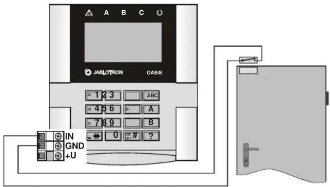
- Install the external hard-wired detector (if required) route its cable through the rear housing and connect to the IN and GND terminals.
-
Enroll the keypad to the control panel (see the control panel installation manual) as follows:
-
Enter enrollment mode in the control panel (if the system does not have a keypad already, briefly short the reset link on the control panel main board, or if a keypad is present, then press key 1 in service mode).
• Install the battery into the keypad to trigger enrollment. -
Exit enrollment mode by pressing the # key.
-
Attach the keypad to the rear housing.
-
Instructions on how to use the keypad can be found in the control panel operating manual.
Keypad menu
The menu can be entered in Service mode by holding the ? key. Then the internal keypad menu will be displayed. Using the arrows on keys 1 and 7 you can scroll through the menu:
| Display Key Description | ||
| Tamper ON | * | Disable / Enable the tamper sensor(only for service purposes) |
| Door chime ON | * | Disable / Enable sound when IN triggered |
| Beeper ON | * | Disable / Enable system sounds |
| Backlight colour | ◀ ▶ | Sets the normal display backlight colour 0 - 7 |
| Warning colour | ◀ ▶ | Sets the warning display backlight colour 0 - 7 |
| Brightness | ◀ ▶ | Sets the display brightness 0 - 9 |
| Contrast | ◀ ▶ | Sets the display contrast 0 - 9 |
| Edit text | * | Entry to keypads text editing |
| English | * | Sets English (reload default texts) |
| Čeština | * | other languages ... |
To exit the menu, press # (exiting also occurs after 60 seconds' inactivity).
Notes:
- It is possible to set a different colour backlight as a warning colour for when a fault is indicated or after an alarm state (warning colour). The user can be visually informed of the status. If unwanted, please set both colours to the same value.
- The menu can be displayed even if the keypad has not been enrolled to the control panel.
- Each keypad has its own menu, i.e. each keypad in the system can have its own unique settings.
- The keypad keeps its settings even if its power is disconnected (settings can only be altered via the keypad menu).
- The menu can also be entered when the * key is kept pressed while the keypad is being powered-up.
Keypad sleep mode
When battery-powered, the keypad saves energy by turning itself off when the cover is closed or automatically after 20 seconds of inactivity (15 minutes in service mode). The keypad is woken up by: opening the keypad's flip cover, pressing any key, or triggering the wired door detector input - see below.
Optional AC adapter
If the keypad is powered by an AC adapter (model: Jablotron DE01-12 for terminals: +U and GND), it will not turn off after 20 seconds of inactivity. If the adapter is used, batteries should still be installed. Only turn on the AC adapter after the keypad unit has been powered up by batteries and the two halves of the housing are back together.
Note: To comply with EN standards the keypad does not indicate the status of the alarm system. If desired, the system setting / unsetting status can be programmed in the control panel to be permanently indicate by the keypad.
Installing a door detector
It is possible to wire up a detector(s) to the keypad. The IN input terminal is triggered when disconnected from GND. The control panel's reaction to the IN input being triggered is a delayed intruder alarm linked to the keypad's address. If desired, another reaction can be programmed in the control panel. The IN input can indicate a door being permanently open (status reaction). If the IN input is not used then it must be shorted to GND.
Note: The lifetime of the battery is reduced proportionally to how frequently the door detector is triggered and how often and how long the keypad is battery-powered.
Testing keypad communication
In service mode, the control panel allows you to measure the keypad's radio signal strength. To test the keypad signal, trigger either its IN input or its tamper sensor.
Note: the control panel measures the strength of the signal transmitted by the keypad. It is impossible to measure the signal strength received by the keypad from the control panel. If the keypad has lost communication with the control panel (e.g. if the control panel is damaged) it would display COMM ERROR a communication error. If you re-power a control panel, which previously worked with a keypad, and the keypad does not function, then we recommend disconnecting the keypad batteries for one minute.
Controlling the PgX output
The PgX output can be switched ON and OFF by pressing the ON (*) and OFF (#) buttons long (for 5 seconds). The function of PgX must be set in the control panel. A long beep confirms the change of the output's state.
Keypad text editing
The most convenient way to edit text is to use a PC running OLink software. To transfer edited text from a PC to the keypad, the keypad (with its batteries installed) has to be connected either to the OASiS system's digital bus (i.e. one cable from the keypad to the control panel, and another cable from the control panel to the PC) or directly from the PC. The texts are transferred by choosing the Save menu in the Texts window in OLink software.
The names can be edited via the keypad in the "Edit Text" menu item – see the control panel installation manual. The edited text is only stored in the keypad unit used for editing.
Battery replacement
The system checks the battery status and if discharged it will inform the user or the installer. The keypad will continue to work but will also indicate a low battery as well as the backlight being reduced. Batteries should be replaced within one week by a qualified technician in service mode. If they are not, the keypad is switched off when the battery power falls under a critical limit.
Note: Both batteries must be always changed together and with identical types (manufacturer). Please allow one minute delay before inserting new batteries.
Removing the keypad from the system
If the keypad is removed from the system, the control panel indicates this event. If you want to uninstall the keypad, it must also be erased in the control panel.
Technical specifications
Power supply 2x lithium batteries type CR123A (3.0V)
Typical battery lifetime approx. 2 years (2 daily activations and no IN usage) External power supply 12 V DC
Standby consumption
Communication frequency
Communication range
RFID cards
Door detector input
Dimensions
Environment according to EN 50131-1
Operating temperature range
EN 50131-1, EN 50131-3, EN 50131-6, EN 50131-5-3
Complies with
Can be operated according to

JABLOTRON ALARMS a.s. hereby declares that the JA-80F is in compliance with the essential requirements and other relevant provisions of Directive 1999/5/ECThe original of the conformity assessment can be found at www.jablotron.com, Technical Support section.

Note: Although this product does not contain any harmful materials we suggest you return the product to the dealer or directly to the producer after use.