
HSU-13VQA22 - Aircondition HAIER - Gratis brugsanvisning og manual
Find enhedens vejledning gratis HSU-13VQA22 HAIER i PDF-format.


Brugerspørgsmål om HSU-13VQA22 HAIER
0 spørgsmål om dette apparat. Besvar dem du kender, eller stil dit eget.
Stil et nyt spørgsmål om dette apparat
Download vejledningen til din Aircondition i PDF-format gratis! Find din vejledning HSU-13VQA22 - HAIER og tag din elektroniske enhed tilbage i hånden. På denne side er alle dokumenter nødvendige for brugen af din enhed offentliggjort. HSU-13VQA22 af mærket HAIER.
BRUGSANVISNING HSU-13VQA22 HAIER

Read the precautions in this manual carefully before operating the unit.
This appliance is filled with R32.
Keep this manual where the user can easily find it.
WARNING:

Read technical manual

Operator' manual; operating instructions
▲Ask your dealer or qualified personnel to carry out installation work. Do not attempt to install the air conditioner yourself. Improper Installation may result in water leakage, electric shocks, fire or explosion.
▲Install the air conditioner in accordance with the instructions in this installation manual
▲Be sure to use only the specified accessories and parts for installation work.
▲ Install the air conditioner on a foundation strong enough to withstand the weight of the unit.
▲Electrical work must be performed in accordance with relevant local and national regulations and with instructions in this installation manual, Be sure to use a dedicated power supply circuit only. The wiring method should be in line with the local wiring standard. The type of connecting wire is H07RN-F.
▲ Use a cable of suitable length, Do not use tapped wires or an extension lead as this may cause overheating, electric shocks, fire or explosion.
▲ All the cables shall have got the local authentication certificate. During installation, when the connecting cables break off, it must be assured that the grounding wire is the last one to be broken off.
▲ If refrigerant gas leaks during installation, ventilate the area immediately.oxic gas may be produced if the refrigerant comes into contact with fire, and explosion may be happen.
▲After completing installation, check for refrigerant gas leakage
▲When installing or relocating the air conditioner, be sure to bleed the refrigerant circuit to ensure it is free of air, and use only the specified refrigerant (R32).
▲Make sure ground connection is correct and reliable. Do not earth the unit to a utility pipe, lightning conductor or telephone earth lead. Imperfect earthing may result in electric shocks.
▲Be sure to install an earth leakage circuit explosion-proof breaker.
▲ The breaker of the air conditioner should be all-pole switch and explosion-proof. The distance between its two contacts should not be no less than 3mm. Such means for disconnection must be incorporated in the wiring.
▲ Do not use means to accelerate the defrosting process or to clean, other than those recommended by the manufacturer.
▲The appliance must be stored in a room without continuously operating ignition sources, the radius of the storage area should be no less than 2.5 m (for example: open flames, an operating gas appliance or an operating electric heater).
▲Do not pierce or burn.
▲Be aware that refrigerants may not contain an odour.
▲The appliance must be installed, operated and stored in a room with a floor area larger than 3m 2 . The room should be well ventilated.
▲ Comply with national gas regulations.
▲This appliance is not intended for use by persons (including children) with reduced physical, sensory or mental capabilities, or lack of experience and knowledge, unless they have been given supervision or instruction concerning use of the appliance by a person responsible for their safety. Children should be supervised to ensure that they do not play with the appliance. Cleaning and user maintenance shall not be made by children.
▲The air conditioner can not be discarded or scrapped Randomly. If you need please contact customer service personnel of Haier to scrap in order to obtain the correct disposal methods.
▲Reusable mechanical connectors and flared joints are not allowed indoor.
Installation Manual of Room Air Conditioner
Preparation
Necessary Tools for Installation
Driver
Nipper
● Hacksaw Pipe cutter
Hole core drill
- Spanner(17,19 and 26mm) Knife
Gas leakage detector or
soap-and-water solution
- Torque wrench
(17mm,22mm,26mm)
• - Flaring tool
• - Measuring tape
Reamer
Power Source
● Before inserting power plug into receptacle, check the voltage without fail. The power source is the same as the corresponding name plate.
● Install an exclusive branch circuit of the power.
● A receptacle shall be set up in a distance where the power cable can be reached. Do not extend the cable by cutting it.
Indoor Unit
● Place, robust not causing vibration, where the body can be supported sufficiently.
- Place, not affected by heat or steam generated in the vicinity, where inlet and outlet of the unit are not disturbed.
● Place, possible to drain easily, where piping can be connected with the outdoor unit.
● Place, where cold air can be spread in a room entirely.
● Place, nearby a power receptacle, with enough space around. (Refer to drawings).
- Place where the distance of more than lm from televisions, radios, wireless apparatuses and fluorescent lamps can be left.
- In the case of fixing the remote controller on a wall, place where the indoor unit can receive signals when the fluorescent lamps in the room are lightened.
Outdoor Unit
● Place, which is less affected by rain or direct sunlight and is sufficiently ventilated.
- Place, possible to bear the unit, where vibration and noise are not increased.
- Place, where discharged wind and noise do not cause a nuisance to the neighbors.
- Place, where a distance marked is available as illustrated in the above figure.
Drawing for the installation of indoor and outdoor units
The models adopt HFC free refrigerant R32
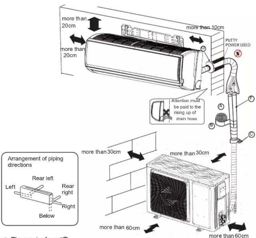
● The marks from tA
G in the figure are the parts numbers.
● The distance between the indoor unit and the floor should be more than 2m.
Please be subject to the actual product purchased, the above picture is just for your reference.
Read this manual before installation
Explain sufficiently the operating means to the user according to this manual
Accessory parts
| No. | Accessory parts | Number of articles |
| 1 | Remote controller | 1 |
| 2 | 2 | |
| 3 | 1 | |
| 4 | 5 | |
| 5 | 2 |
Note:
Accessory parts may vary from each model, pls refer to the actual parts.
Optional parts for piping
(A) Non-adhesive tape
B Adhesive tape
© Saddle (L.S) with screws
(D) Connecting electric cable for indoor and outdoor
E Drain hose
F Heating insulating material
G Piping hole cover
■ Check for Installation and Test Run
■ Please kindly explain to our customers how to operate through the instruction manual.
Check Items for Test Run
□ Put check mark √ in boxes
Gas leak from pipe connecting?
Heat insulation of pipe connecting?
Are the connecting wirings of indoor and outdoor firmly inserted to the terminal block?
Is the connecting wiring of indoor and outdoor firmly fixed?
Is drainage securely carried out?
Is the earth line securely connected?
Is the indoor unit securely fixed?
Is power source voltage abided by the code?
Is there any noise?
Is the lamp normally lighting?
Are cooling and heating (when in heat pump) performed normally?
Is the operation of room temperature regulator normal?
Floor fixing dimensions of the outdoor unit (Unit:mm)

1 Fitting of the Mounting Plate and Positioning of the wall Hole
When the mounting plate is first fixed
- Carry out, based on the neighboring pillars or lintels, a proper leveling for the plate to be fixed against the wall, then temporarily fasten the plate with one steel nail.
- Make sure once more the proper level of the plate, by hanging a thread with a weight from the central top of the plate, then fasten securely the plate with the attachment steel nail.
- Find the wall hole location A using a measuring tape

mod10-13 X: A-502nm B-261nm C-175nm D-110mm E-52mm
m012-16 24-50mm,0-28mm,C-170mm,D-67mm,=42mm
HISU-21M 20732019V14)
mod18 T-A-548nm B-283nm C-170nm D-126nm E-35mm
HEDUCLESHCOOLIKY-TOK-SU-TEARTILSTOCKLIN/ETH
mod22 24T/-64mm, B-255mm, C-173mm D-108mm, E-41mm
(KEU ZOLEYDOCLW, TCHU 2NTRUETCOOIN) TH
(51)24(105+531)Rs(R)
424 mm, 820 mm, C-130 mm, D-100 mm, E-90 mm
15.21.10.06:33:46
mod12P A-90mm D-85mm G-16mm D-90mm E-35mm
-10cm PCC 54.250mm, B 251mm, C 195mm D 128mm, E 41mm
- 2023年1月1日,公司以人民币1,000万元为基准,向银行申请贷款。
m×22.25 4-64mm B-250mm C-173mm D-10
HEU-34TLREOCOLI PA: 1892-2811 to Cxn PA
Pay attention to the following points before installation of machine:
- Take out cushion blocks on
-
Take out cushion blocks on the left and right angle heads
as shown in the following
Figure. -
2017年1月1日
-
Remove 2 gaskets under the
cross-flow fan.
- Clean the burr on the surface of fracture to avoid the power wire from being scratched after removing the virtual opening of the outgoing line slot on the case by hands in indoor power-on process.

When the mounting plate is fixed side bar and lintel
- Fix to side bar and lintel a mounting bar, Which is separately sold, and then fasten the plate to the fixed mounting bar.
- Refer to the previous article, "When the mounting plate is first fixed", for the position of wall hole.
2 Making a Hole on the Wall and Fitting the Piping Hole Cover
• Make a hole of 60 mm in diameter, slightly descending to outside the wall.
• Install piping hole cover and seal it off with putty after installation
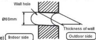
(Section of wall hole)
Indoor side
。
-
F
-
[NO TEXT]
-
-
[NO TEXT]
-
1
-
m = 311
1
0
ut
d
00
or
s
id
c
1
[Non-Text]
C
©
i
F
•
ping
9
r
0
ie
-
p
3 Installation of the Indoor Unit
Drawing of pipe
[ Rear piping ]
- Draw pipes and the drain hose, then fasten them with the adhesive tape
[ Left · Left-rear piping ]
- In case of left side piping, cut away, with a nipper, the lid for left piping.
-
In case of left-rear piping, bend the pipes according to the piping direction to the mark of hole for left-rear piping which is marked on heat insulation materials.
-
Insert the drain hose into the dent of heat insulation materials of indoor unit.
-
Insert the indoor/outdoor electric cable from backside of indoor unit, and pull it out on the front side, then connect them.
-
Coat the flaring seal face with refrigerant oil and connect pipes.
Cover the connection part with heat insulation materials closely, and make sure fixing with adhesive tape

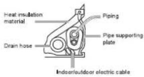
- Indoor/outdoor electric cable and drain hose must be bound with refrigerant piping by protecting tape.
[ Other direction piping ]
- Cut away, with a nipper, the lid for piping according to the piping direction and then bend the pipe according to the position of wall hole. When bending, be careful not to crash pipes.
- Connect beforehand the indoor/outdoor electric cable, and then pull out the connected to the heat insulation of connecting part specially.
Fixing the indoor unit body
- Hang surely the unit body onto the upper notches of the mounting plate. Move the body from side to side to verify its secure fixing.
- In order to fix the body onto the mounting plate, hold up the body aslant from the underside and then put it down perpendicularly.
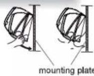
Unloading of indoor unit body
- When you unload the indoor unit, please your hand to arise the body to leave age then lift the bottom of the body outward slightly and lift the unit aslant until it leaves the mounting plate.
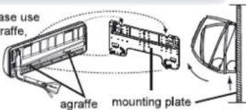
4 Connecting the indoor/outdoor Electric Cable
- Remove terminal cover at right bottom corner of indoor unit, then take off wiring cover by removing its screws.
- Insert from outside the room cable into left side of the wall hole, in which the pipe has already existed.
- Pull out the cable on the front side, and connect the cable making a loop.
- Insert the cable from the back side of the unit, then pull it out on the front side.
- Loosen the screws and insert the cable ends fully into terminal block, then tighten the screws.
- Pull the cable slightly to make sure the cables have been properly inserted and tightened.
- After the cable connection, never fail to fasten the connected cable with the wiring cover.


Note
When connecting the cable, confirm the terminal number of indoor and outdoor units carefully. If wiring is not correct, proper operation can not be carried out and will cause defect.

flowchart
graph LR
    A["Input Module"] --> B["Component 1"]
    B --> C["Component 2"]
    C --> D["Component 3"]
    D --> E["Component 4"]
    E --> F["Component 5"]
    F --> G["Output Module"]
    style A fill:#f9f,stroke:#333
    style G fill:#bbf,stroke:#333
Indoor unit
Out
dc
or it
it
1
ni
do
0
7.4
in
it
[Non-Text]
1
□
td
a
L
in
1
公司
in
0
OF
u
vit
-
广力云智慧零售收银系统
C
u
ld
0
7
in
2
-
n
10
OK
山
hit
-
-
0
ut
0
•
| DATE: 2018-03-04 | ISSUE: 1956-0043 | Model | DATA: 1957-0043 | S110000 | ISSUE: 1957-0043 | Model | DATA: 1957-0043 | S110000 | ISSUE: 1957-0043 |
| Date Number | ISSUE: 1956-0043 | # | S110000 | ISSUE: 1957-0043 | |||||
| ISSUE: 2018 | 2018 | Model | S110000 | ||||||
| ISSUE: 2018 | 2018 | Model | S110000 |
- If the supply cord is damaged, it must be replaced by the manufacturer or its service agent or a similar qualified person. The type of connecting wire is H05RN-F or H07RN-F.
- If the fuse on PC board is broken please change it with the type of T.3.15A/250V.
- The wiring method should be in line with the local wiring standard.
- After installation, the power plug should be easily reached.
- A breaker should be incorporated into fixed wiring. The breaker should be all-pole switch and the distance between its two contacts should be not less than 3mm.
1 Installation of Outdoor Unit
Install according to Drawing for the installation of indoor and outdoor units
2 Connection of pipes
● To bend a pipe, give the roundness as large as possible not to crush the pipe, and the bending radius should be 30 to 40 mm or longer.
● Connecting the pipe of gas side first makes working easier.
● The connection pipe is specialized for R32
Half union
Flare nut
Forced fastening without careful centering may damage the threads and cause a leakage of gas.
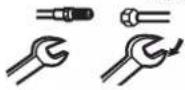
Spanner
Torque wrench
| Pipe Diameter(6) | Fastening torque |
| Liquid side6.35mm(1/4") | 18N.m |
| Liquid/Gas side9.52mm(3/8") | 42 N.m |
| Gas side 12.7mm(1/2") | 55N.m |
| Gas side 15.88mm(5/8") | 60 N.m |
Be careful that matters, such as wastes of sands, etc. shall not enter the pipe. The standard pipe length is 5m. If it is over 7m, the function of the unit will be affected. If the pipe has to be lengthened, the refrigerant should be charged, according to 20 g/m. But the charge of refrigerant must be conducted by professional air conditioner engineer. Before adding additional refrigerant, perform air purging from the refrigerant pipes and indoor unit using a vacuum pump, then charge additional refrigerant.
CAUTION
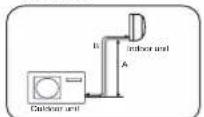

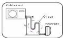
Max.Elevation
18/24K:AM5X=10M
- In case the elevation A is more
than 5m. oil trap shou
installed every 5-7m
Max. Length:
09/12K:8max=16m
18/24K:Bmax=25m In case the pine length B is
- in case the pipe length B is more than 5 m. The refrigerant
should be charged, according
should be charged, to 20 o/m for models.
3 Connection
- Use the same method on indoor unit. Loosen the screws on terminal block and insert the plugs fully into terminal block, then tighten the screws.
- Insert the cable according to terminal number in the same manner as the indoor unit.
- If wiring is not correct, proper operation can not be carried out and controller may be damaged.
● Fix the cable with a clamp.
● Mechanical connectors used indoors shall comply with ISO 14903. When mechanical connectors are used indoors, sealing parts shall be renewed. When flared joints are reused indoors, the flare parts shall be re-fabricated.
4 Attaching Drain-Elbow
- If the drain-elbow is used, please attach it as gure. (Note: Only for heat pump unit.)

5 Purging Method: To use vacuum pump
- Detach the service port's cap of 3-way valve, the valve rod's cap for 2-way valve and 3-way's, connect the service port into the projection of charge hose (low) for gaugemanifold. Then connect the projection of charge hose (center) for gaugemanifold into vacuum pump.
- Open the handle at low in gaugemanifold, operate vacuum pump. If the scale-moves of gause (low) reach vacuum condition in a moment, check 1. again.
- Vacuumize for over 15min. And check the level gauge which should read -0.1MPa (76 cm Hg) at low pressure side. After the completion of vacuumizing, close the handle 'Lo' in gaugemanifold and stop the operation of the vacuum pump. Check condition of the scale and hold it for 1-2min. If the scale-moves back in spite of tightening, make flaring work again, the return to the beginning of 3.
- Open the valve rod for the 2-way valve to an angle of anticlockwise 90 degrees. After 6 seconds, close the 2-way valve and make the inspection of gas leakage.
- No gas leakage?
In case of gas leakage, tighten parts of pipe connection. If leakage stops, then proceed 6. steps

If it does not stop gas leakage, discharge whole refrigerants from the service port. After flaring work again and vacuumize, fill up prescribed refrigerant from the gas cylinder.
- Detach the charge hose from the service port, open 2-way valve and 3-way. Turn the valve rod anticlockwise until hitting lightly.
- To prevent the gas leakage, turn the serviceport's cap, the valve rod's cap for 2-way valve and 3-way's a little more than the point where the torque increases suddenly.
- After attaching the each caps, check the gas leakage around the caps.

flowchart
graph TD
    A["Step 1. 2-way valve Liquid Side\n3-way valve Gas Side"] --> B["Gaugomanifold(for R32)\nAnti countercurrent Joint"]
    B --> C["Tube(for R32)"]
    C --> D["Vacuum pump(for R32)"]
    D --> E["Step 2. Open"]
    E --> F["Step 3. Close"]
    F --> G["Step 4. 2-way valve\nOpen 90°\n3-way valve"]
    G --> H["Step 5. 2-way valve\n1"]
    H --> I["Step 6. 2-way valve\n3-way valve"]
    I --> J["Step 7. Valve rod cap\nValve rod r"]
CAUTION
- If the refrigerant of the air conditioner leaks, it is necessary to discharge all the refrigerant. Vacuumize first, then charge the liquid refrigerant into air conditioner according to the amount marked on the name plate.
- Please do not let other cooling medium, except specified one (R32), or air enter into the cooling circulation system. Otherwise, there will be abnormal high pressure in the system to make it crack and lead to personal injuries.
1 Power Source Installation
● The power source must be exclusively used for air conditioner. (Over 10A)
- In the case of installing an air conditioner in a moist place, please install an earth leakage breaker.
- For installation in other places, use a circuit breaker as far as possible.
2 Cutting and Flaring Work of Piping
● Pipe cutting is carried out with a pipe cutter and burs must be removed.
● After inserting the flare nut, flaring work is carried out.
| Flare tool for R32 | Conventional flare tool | ||
| Clutch-type | clutch-type(Rigid-type) | Wing-nut type (Imperial-type) | |
| A | 0~0.5mm | 1.0~1.5mm | 1.5~2.0mm |
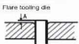


4. Flare pipe
- Insert the spare nut


3 On Drainage
- Please install the drain hose so as to be downward slope without fail. - Please don't do the drainage as shown below.

- Please pour water in the drain pan of the indoor unit, and confirm that drainage is carried out surely to outdoor.
- In case that the attached drain hose is in a room, please apply heat insulation to it without fail.
■ Refrigerant charge label

This product contains fluorinated greenhouse gases covered by the Kyoto Protocol. Do not vent into the atmosphere.
Refrigerant type:R32
GWP* value:675
GWP=global warming potential Please fill in with indelible ink,
• 1 the factory refrigerant charge of the product
• 2 the additional refrigerant amount charged in the field and
- 1+2 the total refrigerant charge on the refrigerant charge label supplied with the product. The filled out label must be adhered in the proximity of the product charging port (e.g. onto the inside of the stop value cover).
A contains fluorinated greenhouse gases covered by the Kyoto Protocol
B factory refrigerant charge of the product: see unit name plate
C additional refrigerant amount charged in the field
D total refrigerant charge
E outdoor unit
F refrigerant cylinder and manifold for charging


- WARNING:
- Installation Manual of Room Air Conditioner
- Preparation
- Necessary Tools for Installation
- Power Source
- Indoor Unit
- Outdoor Unit
- Drawing for the installation of indoor and outdoor units
- Optional parts for piping
- ■ Check for Installation and Test Run
- Fitting of the Mounting Plate and Positioning of the wall Hole
- When the mounting plate is first fixed
- When the mounting plate is fixed side bar and lintel
- Making a Hole on the Wall and Fitting the Piping Hole Cover
- Installation of the Indoor Unit
- Drawing of pipe
- [ Rear piping ]
- [ Left · Left-rear piping ]
- [ Other direction piping ]
- Fixing the indoor unit body
- Unloading of indoor unit body
- Connecting the indoor/outdoor Electric Cable
- Note
- Installation of Outdoor Unit
- Connection of pipes
- Connection
- Attaching Drain-Elbow
- Purging Method: To use vacuum pump
- CAUTION
- Power Source Installation
- Cutting and Flaring Work of Piping
- On Drainage
- ■ Refrigerant charge label
Mærke : HAIER
Model : HSU-13VQA22
Kategori : Aircondition