58210 - Okategoriserad TORO - Gratis bruksanvisning och manual
Hitta enhetens manual gratis 58210 TORO i PDF-format.

Användarfrågor om 58210 TORO
0 fråga om denna apparat. Svara på dem du kan eller ställ din egen.
Ställ en ny fråga om denna apparat
Ladda ner instruktionerna för din Okategoriserad i PDF-format gratis! Hitta din manual 58210 - TORO och ta tillbaka ditt elektroniska enhet i hand. På denna sida publiceras alla dokument som behövs för att använda din enhet. 58210 av märket TORO.
BRUKSANVISNING 58210 TORO
3, 4 AND 5 HP TILLERS
SAFETY INSTRUCTIONS
CAUTION
CAUTION: This tiller is engineered and tested to offer reasonably safe and effective service, provided it is operated in strict accordance with these instructions. FAILURE TO DO SO MAY RESULT IN PERSONAL INJURY.
TRAINING
- Never allow children to operate a tiller or adults to operate it without proper instruction.
- Know the controls and how to stop quickly — READ THE OWNER'S MANUAL.
PREPARATION
- Handle gasoline with care - it is highly flammable.
A. Use approved gasoline container.
B. Fill gas tank outdoors, never while engine is running. Wipe up spilled gasoline.
C. Replace gasoline cap securely.
D. Open doors if engine is run in a garage — exhaust gases are extremely dangerous.
-
Keep children and pets a safe distance away at all times.
-
Inspect the area to be tilled. Remove glass, wire, metal objects, large sticks, and stones.
OPERATION
- Give complete and undivided attention to the job at hand.
- Personal injury may result from debris thrown by this machine. Therefore, always stay a safe distance away from tines.
- Maintain solid and secure footing at all times.
- Never place face in front of tines while tines are rotating.
-
Check before each use for loose fasteners or parts.
-
Stop engine and disconnect spark plug lead wire before cleaning tines, removing obstacles, making adjustments or when leaving operating position.
- Never place hands or feet under or into rotating parts or concealed areas. Keep hands and feet clearly away from tine elements, belts, pulleys etc., while engine is running.
- When striking a hidden object, immediately place throttle in "STOP" position, all controls disengaged, disconnect spark plug lead wire, and check for damage or loose parts. Repair damage at once.
- Do not use tiller in wet soil.
- Wear substantial shoes and long pants while using tiller.
- Never work on tiller while engine is running.
MAINTENANCE
- Keep engine free of debris buildup.
- Follow maintenance instructions as outlined in this manual.
- Have an authorized Toro Service Dealer inspect the tiller each year.
- Disconnect spark plug wire before making any adjustment or repair.
- Store gasoline in an approved red metal container in a cool, dry place.
- Keep machine in good operating condition and keep safety devices in place.
- Safety and performance levels can be assured only by the use of specified Toro replacement parts.
- Maximum engine speed must not exceed 3400 RPM.
TABLE OF CONTENTS
| Page | Page | ||
| Safety Instructions | Front page | Tilling Depth | 5 |
| Foreword | 2 | Maintenance | 6-8 |
| Loose Parts Chart | 2 | Lubrication | 6 |
| General Assembly Instructions | 3 | Servicing Air Cleaner | 6 |
| Preparation Before Starting | 4 | Changing Engine Oil | 6 |
| Filling With Oil | 4 | Changing Transmission Oil | 6 |
| Filling With Gasoline | 4 | Spark Plug | 7 |
| Check Air Cleaner | 4 | Changing Tilling Speed | 7 |
| Know Your Controls | 4 | Changing Tilling Width | 7 |
| Operating Instructions | 5 | Adjusting Tiller Clutch | 7 |
| Break-In Procedure | 5 | Throttle Control Adjustment | 7 |
| Starting | 5 | Carburetor Adjustment (3 HP) | 8 |
| Stopping And Emergency Stopping | 5 | Carburetor Adjustment (4 & 5 HP) | 8 |
| Transport Position (Depth Gauge Bar) | 5 | Off Season Storage | 8 |
| Depth Gauge Bar Use | 5 | Important Ordering Instructions | 9 |
| Operating Tips | 5 | The Toro Promise | 9 |
FOREWORD
TO THE TORO OWNER ...
Toro knows how important proper tilling equipment is for soil conditioning and Toro designers have, over the years, strived for and achieved the finest in tilling products. You, as a Toro owner, share the most advanced methods and machines available today. Give it the proper care, and it will repay you with precision service.
The more you know about the operation and mechanics of your Toro tiller, the better job it will do for you. That's why it is important to read your Owner's Manual from cover to cover before attempting to operate the machine.
Compare the illustrations to your tiller so as to familiarize yourself with locations of controls, lubrication points, and adjustment sites.
Study the Safety Instructions thoroughly to insure proper functioning and to prevent injury to yourself and others.
At times minor changes are made in Toro products to improve their efficiency. Should you notice a variation in your tiller that is not reflected in the Owner's Manual, see your Toro distributor or his authorized Toro Service Dealer (see yellow pages) for information and part numbers.
LOOSE PARTS CHART
| Description | Quantity | Where Used |
| Clevis Pin | 4 | Used to assemble tines and secure assembly to drive shaft. |
| Capscrew | 1 | Used to secure handlebar support to drawbar. |
| Conelock Nut | 1 | Used to secure handlebar support to drawbar. |
| Capscrew | 4 | Used to secure handle assembly to tiller chassis. |
| Conelock Nut | 4 | Used to secure handle assembly to tiller chassis. |
| Washer | 1 | Used with cotter pin to secure clutch rod after rod has been inserted through idler bracket slot. |
| Cotter Pin | 6 | 4 used with Clevis pin, 2 used to secure clutch rod. |
Unpack your tiller with care to avoid damaging the unit or misplacing the loose parts. Carefully inspect the unpacked items to make certain damage has not occurred during shipment. Be sure to locate the loose parts bag containing hardware.
GENERAL ASSEMBLY INSTRUCTIONS
- Position handle assembly to the tiller chassis and secure in place with four (4) capscrews and locknuts.
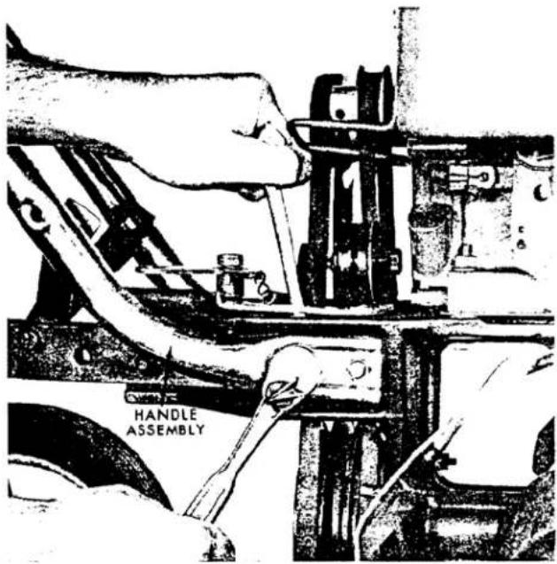
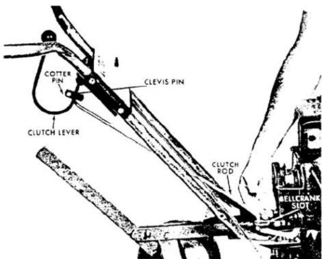
- Install appropriate end of clutch rod through clutch lever and secure with cotter pin.
- Place clutch rod into slot in bellcrank and secure with washer and cotter pin.
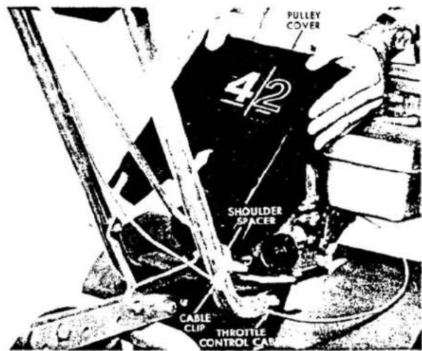
- Slide cable clip and shoulder spacer (shoulder to face outward) on capscrew. Secure right side of handle to right side of handlebar support with capscrew assembly and locknut. Assemble shoulder spacer (shoulder to face outward) on capscrew. Secure left side of handle with capscrew assembly and locknut. Bend clip around throttle control cable. Do not pinch tight. Slide pulley cover (4 & 5 HP) into position on shoulder spacers and snap top in place next to engine.
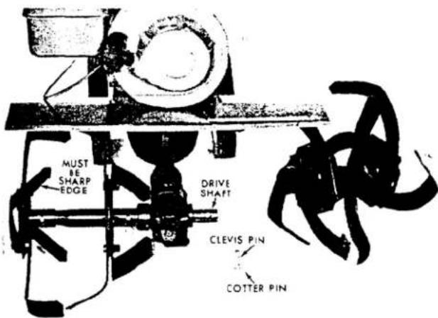
- Assemble right and left tine sections with four (4) clevis pins and cotter pins making sure that leading edge of tine is the sharp edge. Secure tine sections in place on drive shaft with two (2) clevis pins and cotter pins.
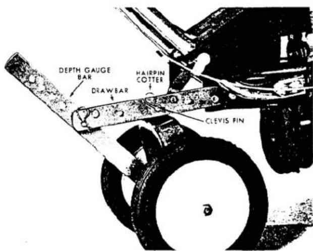
- Secure depth gauge bar in drawbar slot with clevis pin and hairpin cotter.
PREPARATION BEFORE STARTING
The engine has been shipped from the factory without oil and gasoline. Therefore, it is essential that the Preparation Before Starting instructions in this manual be strictly adhered to.
FILLING WITH OIL
- Place tiller on a level surface and remove oil filler plug from engine.
- Using a funnel, slowly pour a good grade of MS classification SAE10-W-40 oil into the crankcase until the point of overflowing.
3 HP - 20 oz. (Approximate)
4 HP - 21 oz. (Approximate)
5 HP - 25 oz. (Approximate)

- After sufficient amount of oil has been added, replace oil filler plug.
- Change oil after the first two (2) hours of operation and check oil level after five (5) operating hours or each time tiller is used.
- Change oil every twenty-five (25) operating hours (See Changing Engine Oil, page 6).
- Check transmission oil level, making sure that chassis is level. If oil is not at the point of overflowing, fill with a
good grade of no. 90 gear oil. Change oil once a year (See Changing Transmission Oil, page 6).
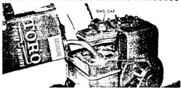
FILLING WITH GASOLINE
Fill the gas tank with a fresh supply of the new automotive anti-pollution unleaded regular gasoline or regular gasoline. Handle gas with care - it is highly flammable. Never add gas to your tiller in an enclosed area. Fill gas tank outdoors and wipe up spilled gas. Never add gas to your tiller while the engine is running. Always take precaution to keep gas and gas storage cans clean. Keep area around gas cap free from debris buildup.
CAUTION: Do not mix oil with gas. Never use premium gas, white stove gas, or gasoline additives.
CHECK AIR CLEANER
Remove Air Cleaner (See Servicing Air Cleaner, page 6) and make sure foam element is lightly oiled.
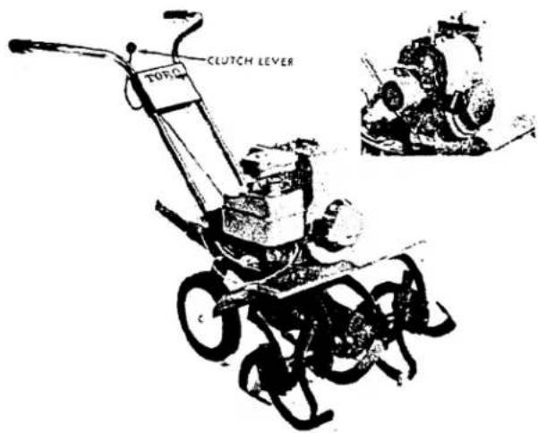
KNOW YOUR CONTROLS
The tiller is equipped with a clutch lever. To engage, push clutch lever forward until locked into position. To disengage, pull clutch lever back and allow it to fall into place. By exerting continuous downward pressure on the clutch lever, unit will be in reverse. This will aid in freeing tines of tangled weeds, getting rid of foreign objects that might be jammed against the tiller, and for backing out of tight places.
OPERATING INSTRUCTIONS
BREAK-IN PROCEDURE
It is important that the transmission and engine be broken in properly. Longer life of the wearing parts will result. Proper break-in is as follows:
- Remove the tines from the drive shaft and place a block or brick under the front of the transmission. Ensure that tiller is level.
- Disengage clutch lever (neutral).
- Start Engine (See Starting, page 5).
- After the engine is started, push clutch lever fully forward and it will lock into engaged position. With the clutch lever in this position (engaged), allow tiller to run for one (1) hour at 34 -full throttle.
- After the above break-in, tiller is ready for use.
STARTING
- Ensure spark plug lead wire is connected to spark plug.
- Clutch should be disengaged.
- Push throttle control lever to "Choke" position.
- Pull recoil starter quickly. Keep firm grip on handle and return rope slowly.
- When engine starts, move throttle control lever between "F" (Fast) and "S" (Slow).
- If engine tends to die, move throttle control lever to "choke" position until engine begins to run smoothly.
- Return throttle control lever between "F" and "S".
STOPPING AND EMERGENCY STOPPING
To stop the engine, pull throttle control lever back to "stop" position and remove spark plug lead wire.
TRANSPORT POSITION (DEPTH GAUGE BAR)
For transporting the tiller, locate depth gauge bar to the two (2) transport holes and secure in place with clevis pin
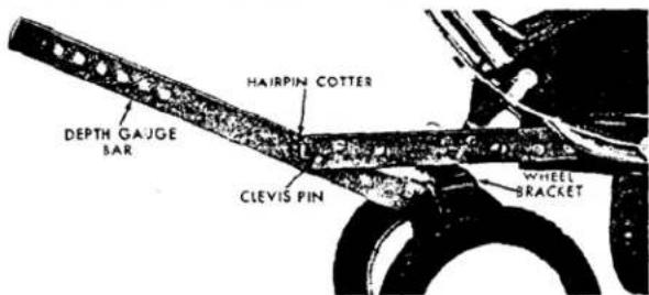
and hairpin cotter. Allow end of bar to rest on under side of wheel bracket.
DEPTH GAUGE BAR USE
When the depth gauge bar drags in the loosened soil, it holds the tiller back, keeping the tines digging to the proper depth. This saves the operator most of the effort of holding the tiller back while it is tilling soil.
When first breaking into untilled soil, hold tiller back manually and allow tiller to turn up hard soil. After enough soil has been loosened to allow depth gauge bar to drag in tilled soil, set bar to desired depth. Proper depth of the gauge bar depends on soil moisture, looseness, and how deep you want the tines to dig. The deeper the bar is set, the deeper the tines will dig. Therefore, depth of the bar should be determined each time the tiller is used — With a little experience, depth can be judged quickly. Proper depth is obtained when operator only has to guide the tiller.
OPERATING TIPS
Rotary tillage prepares garden soil for planting, in one or two operations. Your tiller will effectively do this job for you with a minimum of effort.
The time for using your tiller is governed by conditions of moisture and firmness of the soil. Soil conditions vary widely. It is best not to till the soil when it is too wet or too dry. When it is too wet, the tilled soil tends to ball up into lumps that are hard to work when they dry.
Your tiller is not limited to garden usage. Use it to prepare flower beds and lawn areas for planting. You can operate it to dig as deeply or as lightly as you want. When you have dirt to dig or light grading to do, don't break your back with a pick and shovel. Let your tiller loosen the dirt for you.
As you become familiar with the tiller, you'll discover that it has many other uses.
TILLING DEPTH
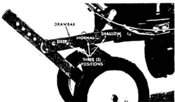
Tilling depth may be changed by moving the wheel location to one of three (3) positions on the drawbar. The hole closes: to the engine is for shallow tilling, the rear hole for deeper tilling, and the middle hole for most tilling applications.
MAINTENANCE
CAUTION: When performing any maintenance on your tiller, disconnect the spark plug lead wire.
LUBRICATION
Keep Tiller Properly Lubricated
- Apply a few drops of SAE20 oil to all pivot points every fifteen (15) operating hours. Occasionally, place a few drops of oil on the wheel bolts.
natural_image
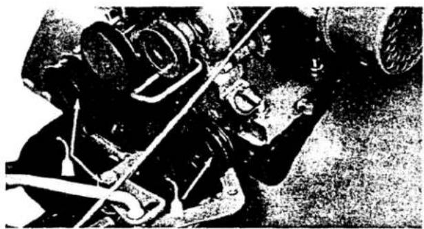
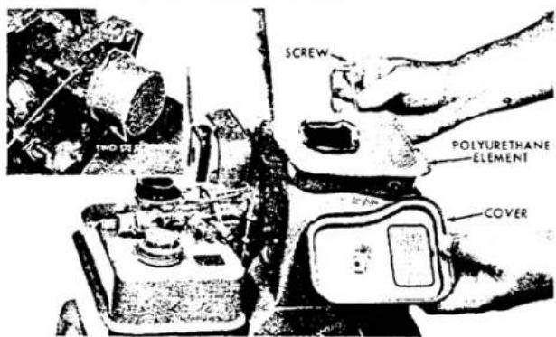
Black-and-white photo of a mechanical device with hoses and components, no visible text or symbolsSERVICING AIR CLEANER
Your engine is equipped with a polyurethane type element. Clean air cleaner and re-oil element every 25 hours under normal conditions. Clean every few hours under extremely dusty conditions. To clean, proceed as follows:
- Remove screw (4 & 5 HP) or two (2) screws (3 HP, See Inset).
- Remove air cleaner carefully to prevent dirt from entering carburetor.
- Disassemble air cleaner and clean.
- Wash polyurethane element in kerosene or a liquid detergent and water to remove dirt.
- Completely dry element by wrapping and squeezing in a cloth.
- Soak element with engine oil. Squeeze to distribute and remove excess oil.
- Reassemble parts and fasten to carburetor.
- Never run engine with air cleaner disassembled.
IMPORTANT: Never run engine without the air cleaner polyurethane element in place.
CHANGING ENGINE OIL
Drain oil while engine is warm and proceed as follows:
- Remove oil drain plug.
- Allow oil to drain into a low shallow pan. Be sure oil drains completely.
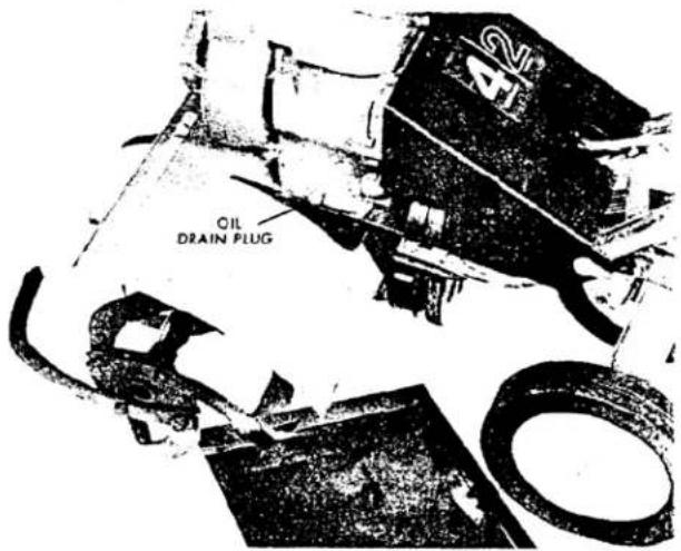
- Replace oil drain plug and refill with fresh oil (See Filling With Oil, page 4).
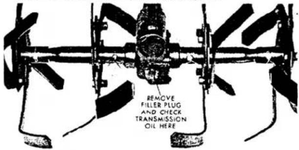
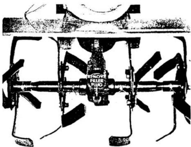
CHANGING TRANSMISSION OIL
Drain oil after tiller has been in operation; oil will be warm and flow easily.
- Remove gas from gas tank.
- Position unit on a flat level surface.
- Remove filler plug.
natural_image
Technical diagram of a mechanical pump assembly with no visible text or symbols-
Tip unit forward and allow oil to drain into a container. Be sure oil drains completely.
-
Refill with a good grade transmission oil (See Filling: With Oil, No. 6, page 4.) Replace filler plug.
MAINTENANCE (CONTINUED)
SPARK PLUG
Use a Champion J-8 or equivalent for replacement. Clean and reset the gap at .030 inches every 25 hours of operation. Apply light coating of graphite grease on threads before replacing plug. If plug is pitted or cannot be cleaned easily, install a new plug.

natural_image
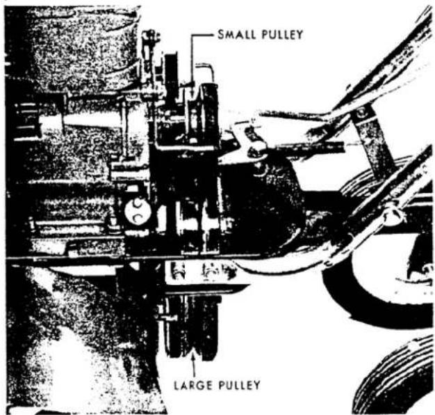
Black-and-white illustration of a hand holding a tool, no visible text or symbolsCHANGING TILLING SPEED (MODELS 58110 & 58210 ONLY)
To change speed, place the clutch in the disengaged position, remove the pulley cover, move the large belt to the adjacent set of forward pulleys (small top pulley and large bottom pulley). Replace pulley cover. Do not change belts while the engine is operating. REMOVE SPARK PLUG LEAD WIRE.
When the belt is on the set of pulleys closest to the engine, the tines revolve less rapidly for better cultivation of small plants.
CHANGING TILLING WIDTH
- If you wish additional tilling width, remove the two blades attached to the outside of the outer tine assembly, on both sides. Interchange the parts, so that the blades curve outward, and reattach tightly.
- The following table shows the tilled widths you can obtain with various tine arrangements.
| Tine Arrangement | Tilled Width |
| Two center tines only | 14" |
| Two center tines and one outside tine only | 17" |
| Center and both outside tines | 20" |
Center and both outside tines, with one outside tine interchanged 23"
Center and both outside tines, with outermost pairs of tines interchanged 26"
ADJUSTING TILLER CLUTCH
After some time belt wear may occur, causing drive belt slippage, resulting in improper clutch operation. The spring in the clutch linkage allows considerable belt wear before an adjustment is necessary. To adjust, proceed as follows:
- At the factory, three flatwashers have been assembled on the engine-mounting bolts.
- Remove engine-mounting bolts and place one (1) of the washers from each bolt between the engine and chassis. Replace engine-mounting bolts.
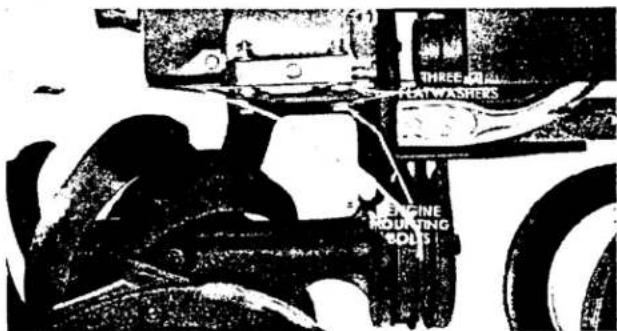
- If one washer does not give sufficient adjustment, use two (2) or three (3) washers on each bolt.
IMPORTANT: Use the SAME NUMBER of washers on each engine mounting bolt - If this instruction is not followed, the engine base or tiller casting may break.
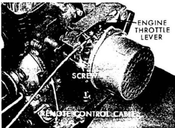
THROTTLE CONTROL ADJUSTMENT
Use the following steps to adjust the throttle control cable at the carburetor:
- Move the throttle control lever on the control panel as far to the rear as possible ("Stop" position).
- Loosen throttle control cable clamp screw (on carburetor) so that cable can move freely.
- Pull control casing forward as far as possible on 4 & 5 HP models. On 3 HP model, pull to rear.
- Secure cable clamp and casing with screw.
MAINTENANCE (CONTINUED)
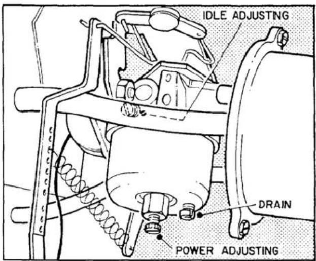
CARBURETOR ADJUSTMENT (3 HP)
Do not make unnecessary adjustments. Factory settings are correct for most applications. If adjustments are needed, proceed as follows:
- Close power adjusting needle by turning to right (clockwise). Close finger tight only. Forcing will cause damage.
- Open one turn (counterclockwise).
- Close idle adjusting needle by turning to right (clockwise). Close finger tight only. Forcing will cause damage.
- Open five/eighths (5/8) turn (counterclockwise) for float feed carburetor.
- Start Engine. Follow starting instructions.
- With throttle open (carburetor control at normal operating position), adjust power adjusting needle one-eighth (1/8) turn at a time forward or backward until engine runs smoothly. If engine tends to stall under load, enrich mixture slightly (counterclockwise).
- Hold throttle lever closed or move carburetor control to "S", "SLOW" position, and adjust idle adjusting needle until engine runs smoothly, proceeding as in step 6 above.
- Allow several seconds between each adjustment when performing either step six (6) or (7), which will allow engine to react to new setting.
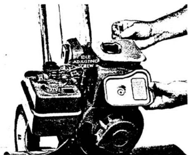
CARBURETOR ADJUSTMENT (4 & 5 HP)
Carburetors are adjusted at the factory and normally do not need adjustment unless they have been disassembled.
INITIAL ADJUSTMENT:
Close needle valve (turn clockwise), then open 1½ turns (turn counter-clockwise). This initial adjustment will permit the engine to be started and warmed up before making final adjustment.
FINAL ADJUSTMENT:
With engine running at normal operating speed (approximately 3000 RPM without load) close the needle valve (turn clockwise) until engine starts to lose speed (lean mixture). Then slowly open needle valve (turn counterclockwise), past the point of smoothest operation, until engine just begins to run unevenly. This mixture should be rich enough for best performance under load.
Hold throttle in idling position. Turn idle adjusting screw until fast idle is obtained (1750 RPM).
Test the engine under full load. If engine tends to stall or die out, it usually indicates that the mixture is slightly lean and it may be necessary to open the needle valve slightly to profide a richer mixture. This richer mixture may cause a slight unevenness in idling.
OFF SEASON STORAGE
In the event tiller is to be stored for any length of time (30 days or more) or at the end of the mowing season, prepare as follows:
- Drain fuel tank completely to prevent gum deposits from forming in the carburetor, fuel line, and gas tank. Run the engine until gas in carburetor has been expanded.
CAUTION: Drain gasoline into container outdoors away from fire or flame.
- Drain crankcase oil while engine is warm. Refill with fresh oil.
- Remove spark plug, pour one (1) ounce of SAE10-W-40 oil into cylinder. Crank engine once to distribute oil. Replace spark plug.
- KEEP THE ENGINE CLEAN. This is an air-cooled engine and clogging of the cooling system may cause serious damage. Keep the blower fins on the flywheel, blower screen, the cylinder and cylinder head free from dirt and foreign material.
IMPORTANT ORDERING INSTRUCTIONS
Repair parts are available from your TORO dealer.
To insure getting correct parts without: delay, please furnish the following information:
- Model and serial number of your tiller as shown on the name plate.
-
Part number, description and quantity of each part required.
-
State whether parts should be shipped by mail or express. All repair parts are shipped F.O.B. factory.
- Name and address where parts are to be shipped.
- Do not order by reference number; use part number only.
THE TORO PROMISE
It is Toro's policy to design and produce Toro products to provide our customers with a high level of performance and durability in normal operation. Our products, however, are produced in high volume, and it is inevitable that occasionally a unit will reach a customer with a defect in materials or workmanship which causes that unit to fall below the normal high level of Toro
performance. Invariably, such a defect will be noticed in a residential product within one year, and in an institutional product within ninety days after purchase. Recognizing this possibility. Toro has established a simple guarantee policy and procedure that is intended to assure customer satisfaction. This guarantee statement is as follows:
The image contains no text. The horizontal lines are stylistic or background elements and must be ignored according to the rules.
The Toro Promise
Toro Manufacturing Corporation promises to repair any TORO product for the original purchaser if defective in materials or workmanship. The following time periods from the date of purchase apply:
Residential products 1 year
Residential products used commercially. . . 45 days
Institutional products 90 days
The costs of parts and labor are included, but the customer pays the transportation costs. Just return any residential product to a TORO Service Dealer, or any institutional product to a TORO distributor.
The image contains a decorative border pattern with repeating curved shapes and dots, resembling stylized text or symbols. According to the guidelines, non-text figures/diagrams are to be ignored. Therefore, no OCR output is generated.
Should you feel that a product is defective, and wish to rely on The Toro Promise. the following procedure is recommended:
- Contact any TORO dealer or distributor, but preferably the dealer or distributor from whom you purchased the product.
- He will instruct you to either return the product to him, or tell you the name and address of your nearest TORO Service Dealer if the product is to be returned to such dealer.
-
Take the product and your original sales slip, or other evidence of purchase date, to the servicing dealer.
-
The servicing dealer will inspect the unit, advise you whether the product is defective and, if so, make all repairs necessary to correct the defect without extra charge to you.
If for any reason you are dissatisfied with the dealer's analysis of the defect or the service he performs, we urge you to contact us. Write:
TORO "Customer Care" Department
8111 Lyndale Avenue South
Minneapolis, Minnesota 55420
MAINTENANCE RECORD