
TX-14S3TL - Televizor PANASONIC - Manual falas për përdoruesin
Gjeni manualet e pajisjes falas TX-14S3TL PANASONIC në format PDF.

Pyetjet e përdoruesve rreth TX-14S3TL PANASONIC
0 pyetje rreth kësaj pajisjeje. Përgjigjuni atyre që njihni ose bëni tuajin.
Bëni një pyetje të re rreth kësaj pajisjeje
Shkarko udhëzimet për tuajin Televizor në format PDF falas! Gjeni manualin tuaj TX-14S3TL - PANASONIC dhe merrni pajisjen tuaj elektronike sërish në duar. Në këtë faqe janë publikuar të gjitha dokumentet e nevojshme për përdorimin e pajisjes suaj. TX-14S3TL e markës PANASONIC.
MANUAL I PËRDORUESIT TX-14S3TL PANASONIC
Panasonic
natural_image
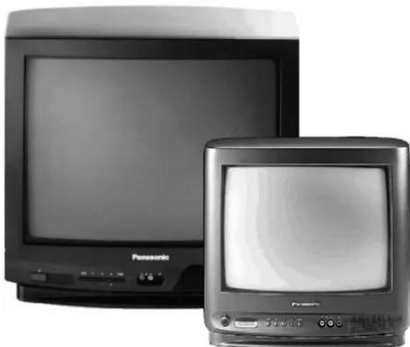
Two vintage Panasonic TVs shown side by side, one front-mounted and one front-mounted (no visible text or labels)TX---21S3TL
TX---14S3TL

Contrast Auto Tracking System

Please read these instructions completely before use and retain them for future reference.
CONTENTS
●Warnings and Precautions 3.
- Accessories 4.
●Fitting Remote Control Batteries 4.
- Installation and Set---up 5.
- Location of Controls .... 7
- Menu Operation 8
- Teletext Operation .... 10
• Audio / Video Connections ..... 11
• VCR Installation 12
• VCR Operation 13
- Trouble-shooting 14
- General Information 14
- Specifications 15
- Scart Terminal Information 15
●This T.V. is designed to operate on A.C. 220 --- 240V, ●C 50Hz and is capable of receiving the PAL I transmission standard.
- Do not expose this TV set to rain or excessive moisture.
●WARNING: HIGH VOLTAGE!
Do not remove the rear cover, there are no user serviceable parts inside.
- Avoid exposing the TV set to direct sunlight or other sources of heat.
- Remove the mains plug from the wall socket when the TV set is not to be used for a prolonged period of time. Do not pull the power cable to remove the mains plug from the socket, always remove it by the plug.
●CABINET AND PICTURE TUBE CARE
Remove the mains plug from the wall socket. The cabir and picture tube can be cleaned with a soft cloth moistened with mild detergent and water. Do not use solutions containing benzol or petroleum. TV sets can produce static electricity, care must be taken whenever touching the TV screen.
- Adequate ventilation is essential to prevent failure of electrical components. We recommend that a gap of at least 5cm is left all around this TV even when it is plain inside a cabinet or between shelves.
FOR YOUR SAFETY PLEASE READ THE FOLLOWING CAREFULLY
This appliance is supplied with a fitted three pin mains plug for your safety and convenience. A 5 amp fuse is fitted in this plug. If the fuse is replaced then the replacement fuse must be 5 amp rated and should be approved by ASTA or BSI to BS136
Check for the ASTA mark

or the
BSI

on the body of the fuse.
If the fitted plug has a removable fuse cover you must ensure that it is refitted when the fuse is replaced. If you lose the fuse cover the plug must not be used until a replacement cover is obtained.
Replacement fuse covers can be purchased through your local Panasonic dealer.
The plug fitted to this appliance incorporates a mains filter circuit. If this is removed or replaced with a non-filtered mains plug this television will no longer meet the European standards for Electromagnetic Compatibility (EMC). If the fitted plug is unsuitable for the socket outlet in your home an appropriate adapter should be used.
Nonetheless, if the fitted plug is replaced, the fuse should be taken out and the cut-off plug disposed of safely. There is danger of severe electrical shock if the cut off plug is inserted into any 13amp. socket.
If a new plug is to be fitted please observe the wiring code as shown below. If in any doubt please consult a qualified electrician.

natural_image
Illustration of a plug with two yellow connectors and a screwdriver inserted (no text or symbols)Important Note : The layout of the mains plug may differ from this illustration
used
How to replace the fuse :
Lift out the removable fuse compartment with a screwdriver and replace the fuse, then refit securely into the mains plug.
IMPORTANT :--The wires in the mains lead of this appliance are coloured in accordance with the following code :-
BLUE : NEUTRAL
BROWN : LIVE
As the colours of the wires in the mains lead of this appliance may not correspond to the markings identifying the terminals in your plug, proceed as follows :---
- The BLUEwire must be connected to the terminal marked 'N' or coloured black.
- The BROWNwire must be connected to the terminal marked 'L' or coloured red.
IMPORTANT NOTE : Under no circumstances should either of these wires be connected to the Earth terminal of the three pin plug, marked with the letter 'E' or the earth symbol ( ).
Check that you have the accessories and items shown


natural_image
3D rendered image of a gray plastic clip or holder with a slot and handle (no text or symbols)T. V. S t a n d (TX---21S3TL only) T S - 2800 S
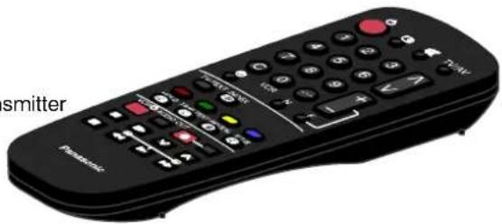
Remote Control Transmitter
TNQ8E0461---2
natural_image
Black remote control with buttons and a 'PANATEX' label, no readable text or symbols beyond the label.

Batteries for the Remote Control Transmitter. (2 x R6 (UM3) size)
FITTING REMOTE CONTROL BATTERIES

Replace the coverSlide off the battery
- Make sure that the batteries are fitted the correct way round.
- Do not mix old batteries with new batteries. Remove old, exhausted batteries immediately.
- Do not mix different battery types, i.e. Alkaline and Manganese. Do not use rechargeable (Ni–Cad) batteries.

TV only
Connect Aerial co---axial cable direct to TV RF IN socket.
* TX---14S3TL only: If required, insert the telescopic aerial into the case socket and connect the cable to the TVRFINsocket. Once inserted, the aerial cannot be removed.
OR
USING A VCR
Connect aerial co---axial cable to RF Input socket of VCR and a RF co---axial cable from VCR RF Out socket to TV RF IN socket.
The VCR can also be connected to the TV using a SCART to SCART lead.
Further details of Audio/ Video connections can be found on page 11.
OR
USING A VCR AND SATELLITE RECEIVER
Connect aerial co---axial cable to RF Input socket of Satellite Receiver. An RF co---axial cable connects from Satellite Receiver RF Out socket to VCR RF IN socket.
A further co---axial cable connects from the VCR RF OUT socket to the TV RF IN socket.
The Satellite Receiver and VCR can also be linked by SCART to SCART lead.
Further information for VCR and Satellite Receiver installation with this TV can be found on page 12.
Ancillary equipment and leads are not supplied.

Switch ON your VCR. *
Switch ON your Satellite Receiver.*
Plug the TV into a mains socket and switch ON.
Programmes will appear immediately if your dealer has programmed the TV for you.

If the TV has not been programmed for you then Auto setup will begin. TV stations will be located and stored ready for use. *
Switch the VCR Test Signal '6ff'. *

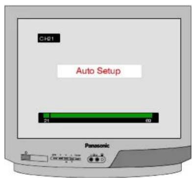

The first available channel will be displayed.

*1. We recommend that you switch ON the VCR's test signal --- refer to your VCR instruction book.
*2. We recommend that your Satellite Receiver is set to either SKY ONE or SKY NEWS to ensure reliable tuning.
*3. If the order in which the stations are stored is not to your preference it can be rearranged. Refer to the Tuning menu Swap feature – seepage9fordetails.
*4. IT IS IMPORTANT that you only use TV programme position '0' to view your VCR. If your VCR picture does not appear on programme position '0' (the VCR position), refer to page 12 for guidance.

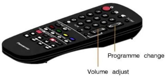
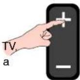
Remote Control keys


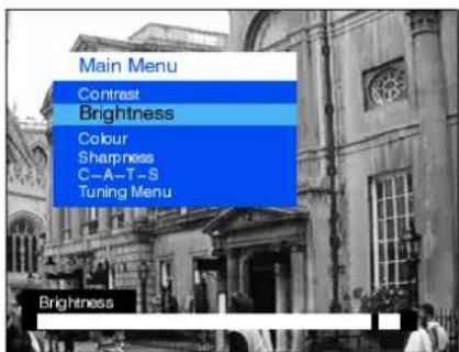
Main Menu
Contrast
Brightness
Colour
Sharpness
The Contrast Brightness, Color and Sharp Sharpness be altered to suit the viewing conditions and personal preferences.
C-- A-- T -- S : Contrast Auto Tracking System
Automatically adjusts the contrast setting to compensate for any changes in the ambient lighting of the surroundings.
To obtain best results first set the Contrast to maximum, to allow a greater operating range for C---A---T---S, then select one of the 3 settings as desired.


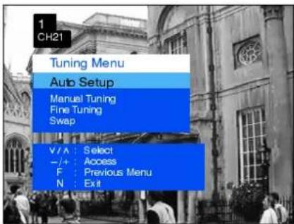
Tuning Menu
The Tüöningne provoide desesedelsstonabott amautmalid automatic tuning menus.
Auto Setup
The AAutoSetSupplementalowals to autotmaticadmationally the time the TV particularly useful if i y o move do area that is served served by a different transmitter.
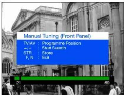
Manual Tuning
The Manaballuringementlowallowisindividugalprogramthepositions to be tuned manually.
Fine Tuning
Stations can be finely tuned using the Fine Tuning adjustment.
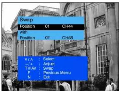
Swap
If the programme order after Auto Setup is not to your preference you can swap programmes between positions.


Manual Tuning (front panel of the television)
The stations may also be manually tuned using the controls on the front of the television.
Press the F key (Front panel) until "Manual Tuning" is reached. Press - or + to access "Manual Tuning".


Teletext is the broadcasting of pages of information on your T.V. screen containing various subjects, the order and availability of which is dependant upon the Broadcasting Companies.
If the Function Select key (F) is pressed whilst in Teletext operation, only the Contrast can be adjusted.

FASTEXT / Normal Automatic Selection
Sub Page Access (Time Text key)
On switching to Teletext, normal mode will be displayed while the teletext information exceeds more than one page, it may search is performed for FASTEXT transmissions, if one is found. take some time for the automatic changing of the sub pages the boxes at the bottom of the screen will change to show the reach the sub page you require. It is possible to enter the available subjects. required sub page and skip the pages in between.
If a FASTEXT signal is not found then the TV will operate in Normal mode whereby the :
Select the required page number using keys 0 --- 9.
Red key moves one page down. Green key moves one page up. Yellow key moves up in blocks of ten pages. Blue key moves up in blocks of 100 pages.
Press TIME TEXT.
Press RED (−) or GREEN (+) to select the required sub page.
Index
In FASTEXT mode, returns to the relevant index page. When the page is found, it will be displayed. Depending on the way information is transmitted, this may have to be pressed more than once to return to the main index page. Press TV/TEXT to exit Teletext operation.
Red / Green / Yellow / Blue keys
Correspond to the FASTEXT or Normal mode coloured boxes.
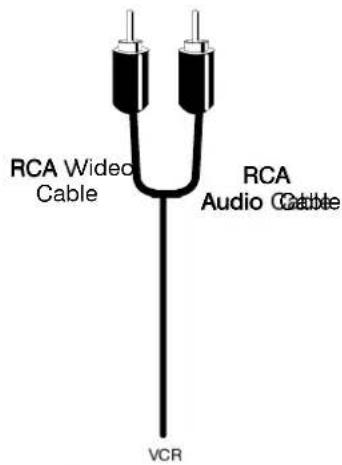
AV (Audio / Video) is a dedicated input for VCR's, Satellite Receivers and other Audio / Video equipment.
This TV is capable of switching to AV operation automatically if the equipment connected provides a switching signal to the SCART socket.
In this condition the display will show EC and it is possible to change the programme position of the TV without changing the displayed picture (this is not possible when using the front AV connections).
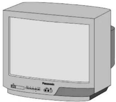
natural_image
Illustration of a Panasonic CRT television with control buttons (no text or symbols on the device body)Video input to V socket
Audio input to A socket
Output fríoram
Headphone
socket
natural_image
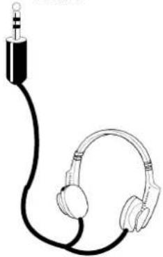
Line drawing of an audio jack with two headphones (no text or symbols)Headphones with 3.5mm jack plug
natural_image
Illustration of a beige electronic device with ports and a control panel (no visible text or symbols)CAMCORDER

natural_image
Illustration of a mounted optical device with lens and adjustment knobs (no text or symbols)
flowchart
graph TD
    A["Input/Output from AVSCARTSocket"] --> B["SCART Cable"]
    B --> C["VCR"]
    C --> D["SATELLITE RECEIVER"]
    D --> E["CAMCORDER"]
    E --> F["COMPUTER (RGB)"]
Ancillary equipment and cables shown are not supplied with this TV set.
Do not connect a computer with TTL output (5V) to this TV set.
The TV's speaker will be automatically disconnected whilst the headphones are connected.
Do not connect front and rear AV inputs simultaneously, as the sound and pictures will be mixed.
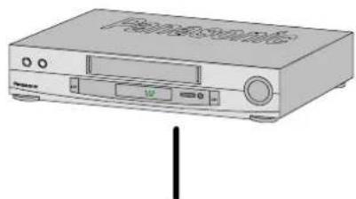
Your new TV is supplied with programme position '0' designed specifically to receive an RF signal from a VCR.
However, depending on the VCR's setting you may not receive any picture or sound from the VCR on programme position '0' of the TV. It will be necessary to either adjust the RF channel of the VCR or to adjust the tuning of the TV's programme position '0' or both until the RF output channel of the VCR is received.
It is intended that this advice is used in conjunction with the instruction books for your ancillary equipment.
TO TUNE YOUR VCR TO THE TV
Insert recorded tape and select playback
Set TV to programme position '0' VCR
Adjust tuning
Operation completed
See below for installation of VCR and Satellite Receiver
TO TUNE YOUR TV TO THE VCR
Access the Manual tuning menu as detailed on page 9.
Programme position and current channel are displayed top left of screen
∨ ∧ To select programme position '0' --- + To start search for VCR playback
If you are going to use a Satellite Receiver and a VCR, it is important, to avoid tuning problems, that they are both tuned to output their signals on different channels. For example, if your VCR is tuned to output channel 32, your Satellite Receiver could be set to output channel 34. Refer to your Satellite Receiver and VCR instruction books for precise tuning information.
The Remote Control is capable of operating some functions of selected Panasonic VCR's, please consult your dealer for details. Some VCR's have different functions, so to ensure compatibility please refer to the VCR's instruction book.

VCR Operating switch
If any difficulty is encountered when using this remote control with Panasonic VCR's please check the operation of the video recorder with the operating switch set at position one and again with the switch set at position two (for details of the location of this switch please refer to Battery Installation and Replacement on page 4).
Before calling for service, determine the symptoms and make a few simple checks as shown below. For service please contact your local Panasonic dealer quoting the model number and serial number (both are located at the rear of the TV).
| Symptoms | Checks | |
| Picture Sound | ||
| Snowy Picture or Multiple Images | Noisy Sound or Normal Sound | Aerial location, direction or connection |
| Interference | Noisy Sound | Electrical appliances, vehicles, fluorescent lights |
| Normal Picture Noisy or No Sound Volume level or sound muted | ||
| No Picture No Sound | Not plugged into A.C. outlet, not switched on picture / sound controls set at minimum levels | |
| No Colour Normal Sound Colour controls set at minimum levels | ||
| Scrambled Normal or Weak Sound Retune channel(s) | ||
GENERAL INFORMATION
Sleep Feature
If the set is not switched off when the TV station stops transmitting, it will automatically go to standby mode after 30 minutes. This function will not operate when in AV mode.
Last Position Memory
Certain functions have a last position memory, i.e. the setting at the time of switch off will be the setting used when the receiver is switched on again:
Programme position
Colour
Volume
Contrast
Brightness
Standby
Sharpness
Status
C-A-T-S
TV Games / Home Computers
Extended use of TV games or home computers with any television set can cause a permanent 'shadow' on the screen. This type of irreversible picture tube damage can be limited by observing the following points :
- Reduce the brightness and contrast levels to a minimum viewing level.
- Do not operate the television set for a continuous period of time while using TV games or home computers.
This type of picture tube damage is not an operating defect and as such is not covered by the Panasonic warranty.
| Model Number: TX--21S3TL TX--14S3TL | ||
| Power Source: 220---240V 50Hz A.C. | ||
Power Consumption: 50W 33V | ||
| Standby Power Consumption: | ||
| Picture Tube: 51cm visible diagonal 34cm visible diagonal | ||
| Audio Output (music) | 6W, 8Ω impedance, mono | |
| Dimensions: | 480 (H) x 520 (W) x 485 (D) mm | 364 (H) x 389 (W) x 384 (D) mm |
| Weight: | 20 kg | 10 kg |
| Receiving Systems: | PAL I UHF E21-69, VHF A1-S20, S21-41 (Hyperband)PAL 525/60 Playback of NTSC tape from PAL Video recorders (VCR) | |
| Aerial (rear): | UHF / VHF | |
| Headphones (front): | 3,5mm, 8Ω impedance, mono | |
| AV - Rear: | 21 pin terminal - Audio/Video in/out, RGB in | |
| AV - Front: | RCA Audio in/RCA Video in | |
Design and specifications are subject to change without notice.
Weight and dimensions shown are approximate.
SCART TERMINAL INFORMATION

- Audio court(R)(R)
- Audio irin(R)(R)
- Audio cout (L)
- Audio earth
- Blue earth
- Audio in (L)
- Blue in
- Status CVBS
- Green earth
-
-
- Green in
- --
- Red earth
- Ground
- Red in
- Status RGB
- CVBS earth
- RGB Status earth
- CVBS out (video)
- CVBS in (video)
- Socket earth
Panasonic Ireland Ltd
Burton Hall Road,
Sandyford Industrial Estate,
Dublin 18
- Panasonic
- CONTENTS
- ●CABINET AND PICTURE TUBE CARE
- FOR YOUR SAFETY PLEASE READ THE FOLLOWING CAREFULLY
- How to replace the fuse :
- FITTING REMOTE CONTROL BATTERIES
- TV only
- OR
- USING A VCR
- USING A VCR AND SATELLITE RECEIVER
- Main Menu
- Sharpness
- C-- A-- T -- S : Contrast Auto Tracking System
- Tuning Menu
- Auto Setup
- Manual Tuning
- Fine Tuning
- Swap
- Manual Tuning (front panel of the television)
- FASTEXT / Normal Automatic Selection
- Sub Page Access (Time Text key)
- Index
- VCR Operating switch
- GENERAL INFORMATION
- Sleep Feature
- Last Position Memory
- TV Games / Home Computers
- SCART TERMINAL INFORMATION
Marka : PANASONIC
Modeli : TX-14S3TL
Kategori : Televizor