ProLite LH5580S - Telewizor IIYAMA - Bezpłatna instrukcja obsługi
Znajdź bezpłatnie instrukcję urządzenia ProLite LH5580S IIYAMA w formacie PDF.

Pytania użytkowników dotyczące ProLite LH5580S IIYAMA
0 pytanie dotyczące tego urządzenia. Odpowiedz na te, które znasz, lub zadaj własne.
Zadaj nowe pytanie dotyczące tego urządzenia
Pobierz instrukcję dla swojego Telewizor w formacie PDF za darmo! Znajdź swoją instrukcję ProLite LH5580S - IIYAMA i weź swoje urządzenie elektroniczne z powrotem w ręce. Na tej stronie opublikowane są wszystkie dokumenty niezbędne do korzystania z urządzenia. ProLite LH5580S marki IIYAMA.
INSTRUKCJA OBSŁUGI ProLite LH5580S IIYAMA
USER MANUAL ProLite
LCD Monitor
ENGLISH
ProLite LH5580S
Thank you very much for choosing the iiyama LCD monitor.
We recommend that you take a few minutes to read this comprehensive manual carefully before installing and switching on the monitor. Please keep this manual in a safe place for your future reference.
TABLE OF CONTENTS
FOR YOUR SAFETY....1
SAFETY PRECAUTIONS....1
SPECIAL NOTES ON LCD MONITORS....3
CUSTOMER SERVICE 4
CLEANING 4
BEFORE YOU OPERATE THE MONITOR....5
FEATURES....5
CHECKING THE CONTENTS OF THE PACKAGE 6
UNPACKING 7
CONTROLS AND CONNECTORS : MONITOR....8
INSTALLATION 10
CONTROLS AND CONNECTORS : REMOTE CONTROL......17
PREPARING THE REMOTE CONTROL....18
BASIC OPERATION....19
CONNECTING YOUR MONITOR....22
COMPUTER SETTING 26
OPERATING THE MONITOR....27
ADJUSTMENT MENU CONTENTS....29
SCREEN ADJUSTMENTS....47
POWER MANAGEMENT FEATURE....50
TROUBLE SHOOTING 51
RECYCLING INFORMATION....52
APPENDIX 53
SPECIFICATIONS....53
DIMENSIONS....54
COMPLIANT TIMING....55
PIP SUPPORT SCREEN TABLE 56
FOR YOUR SAFETY
SAFETY PRECAUTIONS
WARNING
STOP OPERATING THE MONITOR WHEN YOU SENSE TROUBLE
If you notice any abnormal phenomena such as smoke, strange sounds or fumes, unplug the monitor and contact your dealer or iiyama service center immediately. Further use may be dangerous and can cause fire or electric shock.
NEVER REMOVE THE CABINET
High voltage circuits are inside the monitor. Removing the cabinet may expose you to the danger of fire or electric shock.
DO NOT PUT ANY OBJECT INTO THE MONITOR
Do not put any solid objects or liquids such as water into the monitor. In case of an accident, unplug your monitor immediately and contact your dealer or iiyama service center. Using the monitor with any object inside may cause fire, electric shock or damage.
INSTALL THE MONITOR ON A FLAT, STABLE SURFACE
The monitor may cause an injury if it falls or is dropped.
DO NOT USE THE MONITOR NEAR WATER
Do not use where water may be splashed or spilt onto the monitor as it may cause fire or electric shock.
OPERATE UNDER THE SPECIFIED POWER SUPPLY
Be sure to operate the monitor only with the specified power supply. Use of an incorrect voltage will cause malfunction and may cause fire or electric shock.
PROTECT THE CABLES
Do not pull or bend the power cable and signal cable. Do not place the monitor or any other heavy objects on the cables. If damaged, the cables may cause fire or electric shock.
ADVERSE WEATHER CONDITIONS
It is advisable not to operate the monitor during a heavy thunder storm as the continual breaks in power may cause malfunction. It is also advised not to touch the plug in these circumstances as it may cause electric shock.
CAUTION
INSTALLATION LOCATION
Do not install the monitor where sudden temperature changes may occur, or in humid, dusty or smoky areas as it may cause fire, electric shock or damage. You should also avoid areas where the sun shines directly on the monitor.
DO NOT PLACE THE MONITOR IN A HAZARDOUS POSITION
The monitor may topple and cause injury if not suitably located. Please also ensure that you do not place any heavy objects on the monitor, and that all cables are routed such that children may not pull the cables and possibly cause injury.
MAINTAIN GOOD VENTILATION
Ventilation slots are provided to keep the monitor from overheating. Covering the slots may cause fire. To allow adequate air circulation, place the monitor at least 10 cm (or 4 inches) from any walls.
Do not remove the tilt stand when operating the monitor. Ventilation slots on the back of the cabinet will be blocked and the monitor may overheat if the stand is removed. This may cause fire or damage. Operating the monitor on its back, side, upside down or on a carpet or any other soft material may also cause damage.
DISCONNECT THE CABLES WHEN YOU MOVE THE MONITOR
When you move the monitor, turn off the power switch, unplug the monitor and be sure the signal cable is disconnected. If you do not disconnect them, it may cause fire or electric shock.
UNPLUG THE MONITOR
If the monitor is not in use for a long period of time it is recommended that it is left unplugged to avoid accidents.
HOLD THE PLUG WHEN DISCONNECTING
To disconnect the power cable or signal cable, always pull it by the plug. Never pull on the cable itself as this may cause fire or electric shock.
DO NOT TOUCH THE PLUG WITH WET HANDS
Pulling or inserting the plug with wet hands may cause electric shock.
WHEN YOU INSTALL THE MONITOR ON YOUR COMPUTER
Be sure the computer is strong enough to hold the weight of the monitor, otherwise, you may damage your computer.
REMARK FOR 24/7 USAGE
This product is not specifically designed for 24/7 usage in all environments.
OTHERS
ERGONOMIC RECOMMENDATIONS
To eliminate eye fatigue, do not operate the monitor against a bright background or in a dark room. For optimal viewing comfort, the monitor should be just below eye level and 40-60 cm (16-24 inches) away from your eyes. When using the monitor over a prolonged time, a ten minute break every hour is recommended as looking at the screen continuously can cause eye strain.
SPECIAL NOTES ON LCD MONITORS
The following symptoms are normal with LCD monitors and do not indicate a problem.
NOTE
■ When you first turn on the LCD monitor, the picture may not fit in the display area because of the type of computer that is used. In this case, adjust the picture position to the correct position.
■ Due to the nature of the backlight, the screen may flicker during initial use. Turn off the Power Switch and then turn it on again to make sure the flicker disappears.
■ You may find slightly uneven brightness on the screen depending on the desktop pattern you use.
■ Due to the nature of the LCD screen, an afterimage of the previous screen may remain after switching the image, when the same image is displayed for hours. In this case, the screen is recovered slowly by changing the image or turning off the Power Switch for hours.
■ Contact your dealer or iiyama service center for the backlight replacement when the screen is dark, flickering or not lighting up. Never attempt to replace it by yourself.
■ Max. non-stop operating time and conditions
(1) If a static image is displayed continuously, it is recommended to disrupt it with a motion picture.
(2) It is recommended to periodically change the background colour and background image.
(3) Maximum operating time of the display is 24 hours/7 days, if the Screen Saver (MOTION mode) function is set on. If the Screen Saver function is off, do not exceed a 12 hours non-stop operating time limit.
(4) If the screen is active for a longer period of time, it is recommended to I. Run the screensaver of the picture output device (motion picture or black pattern) II. Power off the system for a while
(5) Make sure that the screen is suitably ventilated, or is used in conjunction with climate control system if installed into any bespoke cabinets.
(6) We strongly recommend an active cooling system with fans for long operating times, especially for high luminance LCD models.
■ This LCD cannot be used outdoors.
CUSTOMER SERVICE
NOTE
■ If you have to return your unit for service and the original packaging has been discarded, please contact your dealer or iiyama service center for advice or replacement packaging.
CLEANING
WARNING
■ If you drop any materials or liquids such as water into the monitor when cleaning, unplug the power cable immediately and contact your dealer or iiyama service center.
CAUTION
■ For safety reasons, turn off the power switch and unplug the monitor before you clean it.
NOTE
■ To protect the LCD panel, do not scratch or rub the screen with a hard object.
■ Never use any of the following strong solvents. These will damage the cabinet and the LCD screen.
Thinner
Benzine
Abrasive cleaner
Spray-type cleaner
Wax
Acid or Alkaline solvent
■ Touching the cabinet with any product made from rubber or plastic for a long time may cause degeneration or loss of paint on the cabinet.
CABINET
Stains can be removed with a cloth lightly moistened with a mild detergent solvent. Then wipe the cabinet with a soft dry cloth.
LCD
Periodic cleaning with a soft dry cloth is recommended.
SCREEN
Don't use tissue paper etc. because these will damage the LCD screen.
BEFORE YOU OPERATE THE MONITOR
FEATURES
◆ Supports Resolutions up to 1920 × 1080
◆ High Contrast 4000:1 / Brightness 450cd/m²
◆ Digital Character Smoothing
◆ Automatic Set-up
◆ Stereo Speakers
2 × 10W Stereo Speakers
◆ Plug & Play VESA DDC2B Compliant Windows® XP/Vista/7/8 Compliant
Power Management (ENERGY STAR® VESA DPMS Compliant)
◆ VESA Mounting Standard (400mm×400mm) Compliant
CHECKING THE CONTENTS OF THE PACKAGE
The following accessories are included in your package. Check to see if they are enclosed with the monitor. If anything is missing or damaged, please contact your local iiyama dealer or regional iiyama office.
 or EUPower Cable * or EUPower Cable * |  Screw(M4) x2(For the monitor fall prevention clampers) Screw(M4) x2(For the monitor fall prevention clampers) | [AZBX]Corner protector x4 |
 or UKPower Cable * or UKPower Cable * | 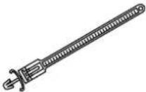 Clamper x3(For tying cables) Clamper x3(For tying cables) |  Screw(M3) x4 (For the corner protectors) Screw(M3) x4 (For the corner protectors) |
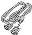
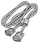 VGA (D-sub) Signal Cable VGA (D-sub) Signal Cable | 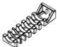 Clamper x2(For holding the HDMI cables) Clamper x2(For holding the HDMI cables) |  Option slot cover Option slot cover |
 DVI-D Signal Cable DVI-D Signal Cable |  Band x4(For the HDMI cable holding clampers) Band x4(For the HDMI cable holding clampers) |  iiyama Logo Sticker iiyama Logo Sticker |
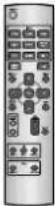 Remote Control Remote Control |  Wall mount spacer x9 Wall mount spacer x9 |  Safety Guide Safety Guide |
 Clamper x2(For fall prevention) Clamper x2(For fall prevention) | 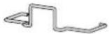 Cable Holder (For holding the power cable) Cable Holder (For holding the power cable) |  Quick Start Guide Quick Start Guide |
CAUTION
* The rating of the Power Cable enclosed in 120V area is 10A/125V. If you are using a power supply higher than this rating, then a power cable with a rating of 10A/250V must be used. However, all guarantees and warranties are void for any problems or damage caused by a power cable not supplied by iiyama.
UNPACKING
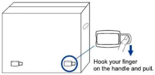
① Before unpacking your monitor, prepare a stable, level, and clean surface near a wall outlet. Set the LCD Monitor box in an upright position and open from the top of the box before removing the top cushions.
② Remove the carton holders.
③ Remove the top cushion and take the accessories box and the Monitor out.
text_image
Hook your finger on the handle and pull.CAUTION
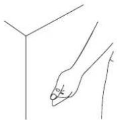
Moving the monitor requires at least two people. If not, it may drop and could result in a serious injury.
When moving/shipping the monitor, please hold by the carton holders.
natural_image
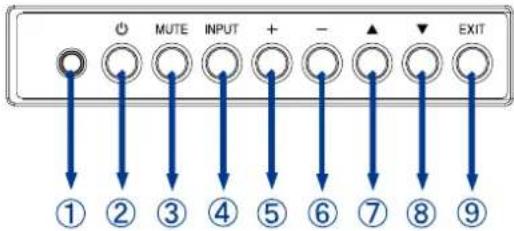
Simple line drawing of a hand holding a vertical line next to a 3D cube structure (no text or symbols)CONTROLS AND CONNECTORS : MONITOR
text_image
MUTE INPUT + - EXIT ① ② ③ ④ ⑤ ⑥ ⑦ ⑧ ⑨| 1 | Ambient Light Sensor | Detects ambient lighting conditions around the Monitor and adjusts screen brightness automatically when the Ambient Light Sensor function is activated. |
| 2 | Power Button | |
| 3 | MUTE | Mute Button |
| 4 | VIDEO SOURCE | Input Select Button |
| 5 | + | + Button |
| 6 | - | - Button |
| 7 | ▲ | Up Button |
| 8 | ▼ | Down Button |
| 9 | EXIT | Exit Button |
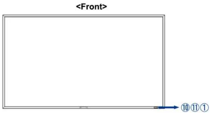
text_image
| 10 | Power Indicator | Green | Steady: Normal Operation |
| Red | Steady: Power OffFlash: The LCD monitor has an error (detected by the self-diagnostic function). | ||
| Green&Red | Steady: Power ManagementSteady(Red) and Flash(Green):The LCD monitor is in the schedule standby mode. | ||
| Off | Main Power Off | ||
| 11 | Remote Sensor | Remote Sensor | |
About the Power
Within 2 seconds after turning off the power using the POWER button on the wireless remote control or on the monitor or by a communication command, don't turn off the main power switch, don't disconnect the power cord or don't turn off the breaker. If the AC power is turned off immediately after switching the display off, all the OSD settings including the language selection may be reset to the factory default settings.
8 BEFORE YOU OPERATE THE MONITOR
text_image
| 12 | MAIN POWER SWITCH | POWER SWITCH | Main Power Switch |
| 13 | AC IN | AC-INLET | AC Connector |
| 14 | USB Hub | 1Upstream(SeriesB)2Downstream(SeriesA) | USB Connector |
| 15 | DisplayPort (DP) | DisplayPort | DisplayPort Connector |
| 16 | HDMI1/HDMI2 | HDMI | HDMI Connector |
| 17 | DVI-D IN | DVI-D 24pin | DVI-D 24pin Connector |
| 18 | DVI-D OUT | DVI-D 24pin | DVI-D 24pin Connector |
| 19 | D-SUB/YPbPr IN | VGA(D-sub) mini 15pin | D-SUB mini 15pin Connector |
| 20 | RS232C IN | D-SUB 9pin | RS232C Connector |
| 21 | RS232C OUT | D-SUB 9pin | RS232C Connector |
| 22 | LAN | RJ45 | LAN Connector |
| 23 | SPEAKERS OUT | Jack | External Speakers Connector |
| 24 | AUDIO OUT | Mini Jack | Audio output Connector |
| 25 | AUDIO IN (PC Audio In) | Mini Jack | Audio Connector |
| 26 | VIDEO OUT | BNC | Video Connector |
| 27 | VIDEO IN | BNC | Video Connector |
| 28 | S-VIDEO IN | Mini Din 4pin | S-Video Connector |
| 29 | Option Slot | Option Slot | |
| 30 | Handles | Handles | |
| 31 | SPEAKERS | Speakers | |
| 32 | Keyhole for Security Lock* | Keyhole for Security Lock |
NOTE
You can fasten a security lock and cable to prevent the monitor from being removed without your permission.
INSTALLATION
CAUTION
■ Follow the manual instructions for the type of mount you have selected. Refer all servicing to qualified service personnel.
■ Moving the monitor requires at least two people.
■ Before installing, please make sure the wall is strong enough to hold the necessary weight of the display and the mount.
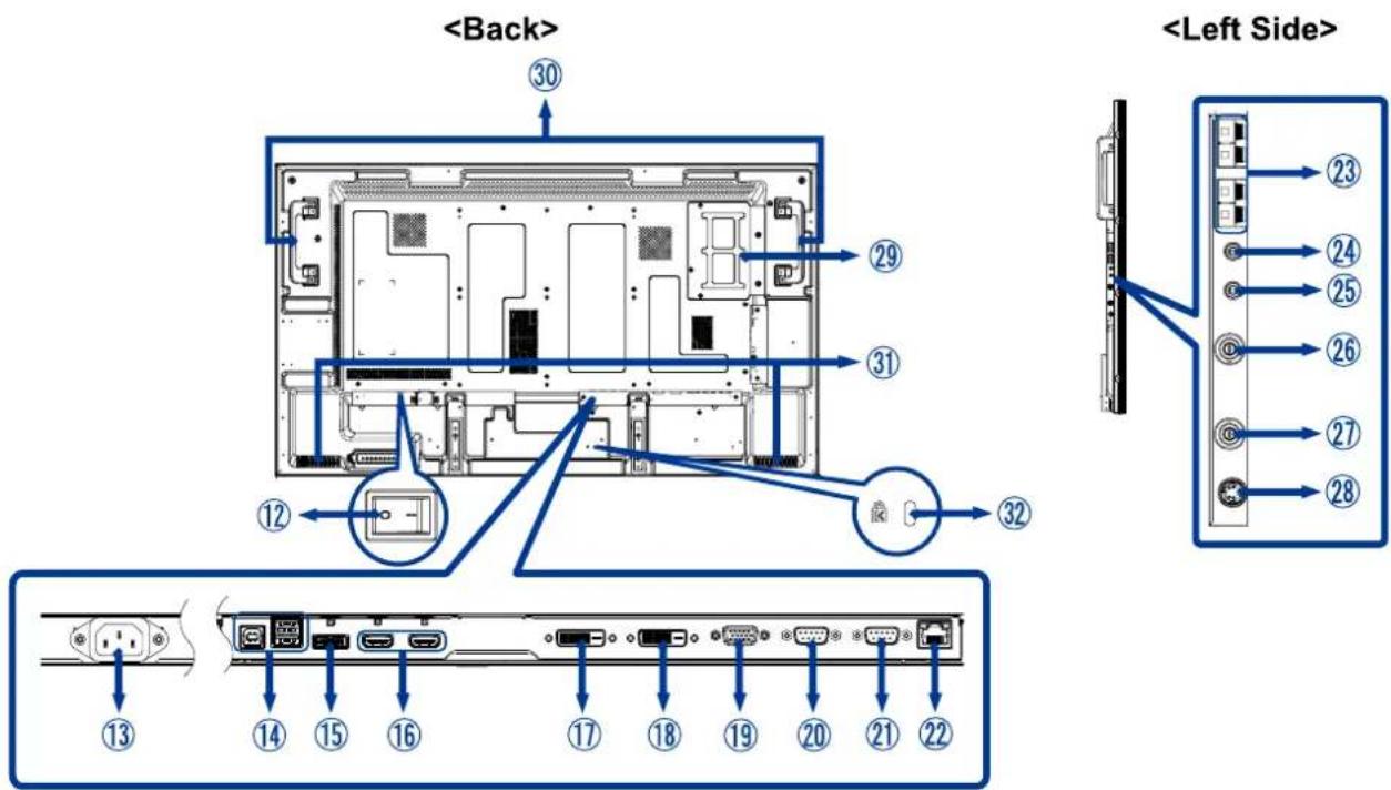
[VENTILATION REQUIREMENTS FOR ENCLOSURE MOUNTING]
CAUTION
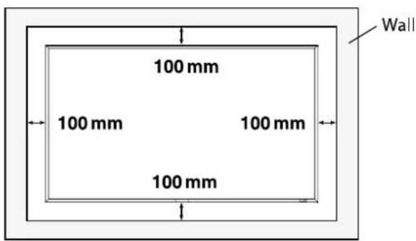
Don't block the holes in the rear of the monitor shown in the figure above. If they are blocked, heat accumulates inside the monitor, causing breakdown. The upper limit of the operation guaranteed ambient temperature when the monitor is installed in the landscape position is 40°C. When installing the monitor in a case or an enclosure, ensure adequate ventilation to keep the temperature inside the case 40°C or lower by providing a cooling fan or ventilation holes in the case. The upper limit when the monitor is in the portrait or face-up position is 35°C. This LCD has a temperature sensor and cooling fan. If the LCD becomes hot, the cooling fan will turn on automatically. If the LCD becomes overheated, the "Caution" menu will appear. If the "Caution" menu appears, stop using the monitor and allow it to cool. When the LCD display is used in an enclosure or with protection on LCD surface, please check the inside temperature of the monitor by "HEAT STATUS" (See page 42). If the temperature is higher than the normal level, set "COOLING FAN" to ON using the SCREEN SAVER function (See page 35).
text_image
100 mm 100 mm 100 mm 100 mm Wall
text_image
Don't block these holes.[TO AVOID THE MONITOR FROM FALLING]
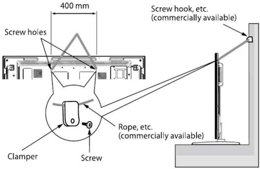
CAUTION
When installing the monitor using the tabletop stands (option), take measures to prevent the monitor from falling over in case of an earthquake or other disaster to lessen the probability of injury and damage resulting from the fall. As shown in the figure, secure the monitor to a solid wall or pillar using rope (commercially available) strong enough to bear the weight of the monitor. [approximately 30.1 kg (with the optional stands)] When using screw hooks (commercially available), use ring hooks, not C-hooks (with opening).
text_image
Screw holes 400 mm Screw hook, etc. (commercially available) Clamper Screw Rope, etc. (commercially available)CAUTION
- The effect of the fall prevention substantially depends on the strength of brackets and base to which the fall prevention devices is attached. When you cannot ensure sufficient strength, provide adequate reinforcement.
- Though the recommended fall prevention is intended to lessen the probability of injury and damage, it doesn't assure its effectiveness against any kind of earthquake or disaster.
- Do not sleep where the monitor may topple over or fall in case of an earthquake or other disaster.
- Before moving the monitor, remove the rope that is securing the monitor. Failure to do so may result in injury or breakdown of the monitor.
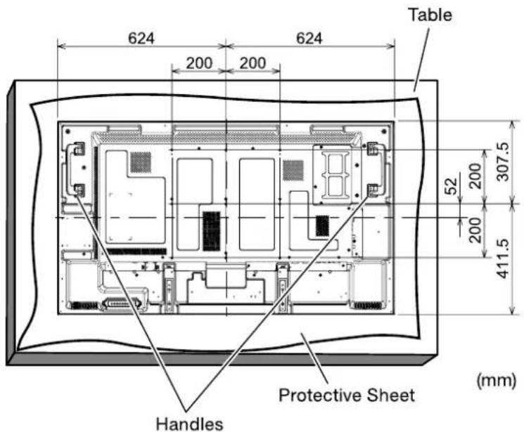
[USING THE WALL MOUNT OR CEILING MOUNT]
Lay the screen face down
Lay the protective sheet on a table, which was wrapped around the monitor when it was packaged, beneath the screen surface so as not to scratch the screen surface.
This device cannot be used or installed without the Tabletop Stand or other mounting accessory. Failure to follow the correct mounting procedures can result in damage to the equipment or injury to the user or installer. Product warranty does not cover damage caused by improper installation. Failure to follow these recommendations can void your warranty.
For installation, use M6 screws (with a loose-proof spring washer and having a length 10 mm longer than the thickness of the mounting bracket) and tighten them securely.
text_image
624 624 200 200 Table 52 200 307.5 200 411.5 Protective Sheet (mm) HandlesCAUTION
For preventing the monitor from falling:
• Install the monitor with metal brackets for wall or ceiling installation (commercially available) on your own responsibility. For detailed procedures of installation, refer to the instructions of the metal brackets.
• To lessen the probability of injury and damage resulting from fall of the monitor in case of earthquake or other disaster, be sure to consult the bracket manufacturer for installation location.
- To lessen the risk of falling of the monitor, thread commercially available rope through the handles at the right and left of the monitor and secure the rope to the wall mount brackets or ceiling mount brackets. Use rope that can bear a load 6 times the weight of the monitor (55" approximately 171 kg; ).
- Do not sleep where the monitor may topple over or fall in case of an earthquake or other disaster.
- Use screws having enough strength to support the LCD display monitor (made of stainless steel etc.).
About the metal bracket:
- Use a VESA-compliant metal bracket.
- Before installation, make sure that the installation surface has sufficient strength.
- Use a metal bracket (commercially available) that is strong enough to hold the monitor.
- Before installation, check the strength and other properties to ensure the safety.
- Do not block the heat dissipating holes in the monitor with the metal bracket. See page 14.
- For details of the mounting procedure and the safe installation procedure, see the user instructions of the metal bracket (commercially available) to be used.
• Take measures such as using multiple metal brackets, holding the monitor at several points, and taking measures to prevent falling or dropping in case of a problem.
[PREVENTING THE HANDLES FROM TOUCHING THE WALL]
By attaching the handles in the opposite orientation, you can reduce the depth of the monitor.
- Remove the screws that are holding the handles.
![IIYAMA ProLite LH5580S - [PREVENTING THE HANDLES FROM TOUCHING THE WALL] - 1](/content/2026/06/1173340/images/b81bd0e2d9b82ccd14b73984ad7ff9ade78d4f89f0a51ff2271d9c346333748d.jpg)
text_image
Handle Screws Screw x 4- Attach the handles in the opposite orientation and secure them using the screws you have removed in step 1.
![IIYAMA ProLite LH5580S - [PREVENTING THE HANDLES FROM TOUCHING THE WALL] - 2](/content/2026/06/1173340/images/c37a99d14df730052f6431bf7bc9774e82c8242cb3d157612ae15b55e2a0416c.jpg)
text_image
Handle Screws Screw x 4[REMOVING THE STAND GUIDE FRAMES]
By removing the stand guide frames, you can reduce the depth of the monitor.
- Remove the screws that are holding the stand guide frames.
![IIYAMA ProLite LH5580S - [REMOVING THE STAND GUIDE FRAMES] - 1](/content/2026/06/1173340/images/0ac1ccdcec7358379e3ab54f6240a80317aa9dda364fb5557c53629d221bb2a2.jpg)
text_image
Screw x 4 Screws Stand guide frame2.Slightly move and remove the stand guide frames.
NOTE
Retain the stand guide frames and the screws that you have removed because they are necessary to install the monitor using the option stands.
[USING THE WALL MOUNT SPACERS]
When the option slot cover or the stand guide frames touch the wall or block the heat dissipating holes in the rear of the monitor, use the wall mount spacers (accessories) to mount the metal bracket (commercially available).
Put the wall mount spacers (9 pcs.) between the metal bracket and the wall mount screw holes of the monitor and attach them using screws (a).
![IIYAMA ProLite LH5580S - [USING THE WALL MOUNT SPACERS] - 1](/content/2026/06/1173340/images/713941aca98648d2a494aa793ef50b9c747e3efba36f10dee366cdc13b0646a6.jpg)
text_image
(a) Wall mount spacer (accessory)(a): Screw for attaching the wall mount spacer (M6, 9 pcs.)
[WALL MOUNTING]
![IIYAMA ProLite LH5580S - [WALL MOUNTING] - 1](/content/2026/06/1173340/images/04698c972cfe90caa6ebbde2ea0cf1f8d9094840471641a3f1725801d7939dff.jpg)
text_image
Screw Bracket 17 mm Wall mount spacer Chassis LCAUTION
When using the wall mounting, consideration of thickness of the mounting stage needs to be taken. Tighten the M6 Screw with washer which "L" length is 10mm to fasten the monitor.
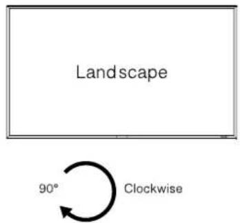
[INSTALLING IN THE PORTRAIT OR FACE-UP POSITION]
The monitor can be installed in the portrait or face-up position.
Ensure that the monitor is oriented as shown below.
CAUTION
- The operating environmental condition (temperature) when the monitor is in the portrait or face-up position is 0°C to 35°C.
- Proper operation of the monitor is not guaranteed when it is not mounted as shown below (upside down, face down, etc.).
- In the portrait or face-up position, the lifetime of the backlight is shorter than that in the landscape position.
- When the monitor is in the face-up position, be sure to set COOLING FAN to ON using SCREEN SAVER in the CONFIGURATION1 menu of the OSD screen function.
Installation in the portrait position
The logo should be on the LEFT side when viewed from the front of the monitor.
NOTE
This monitor doesn't have a function to rotate displayed images. To display images in the portrait orientation, use already rotated images.
text_image
Landscape 90° Clockwise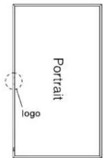
text_image
Portrait logo
text_image
PortraitInstallation in the face-up position
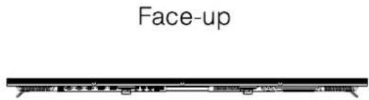
text_image
Face-up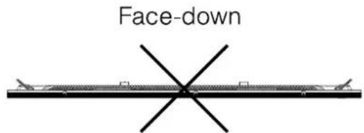
text_image
Face-downOperation environment for portrait or face-up installation
When the monitor is installed in the portrait or face-up position, the following conditions should be satisfied.
Temperature
0 - 35°C / 32 - 95°F
Humidity
20 - 80% (without condensation)
[ATTACHING THE CORNER PROTECTORS]
CAUTION
It is recommended to use the corner protectors (accessories). When installing the monitor, hold its body firmly. If you hold the monitor by the corner protectors when moving it, the monitor may detaches and fall from the corner protectors, causing injuries.
Attach the corner protectors using the accessory screws (c)
text_image
(c) (c) (c) (c) (c)(c): Screw for attaching the corner protector (M3, 4 pcs.)
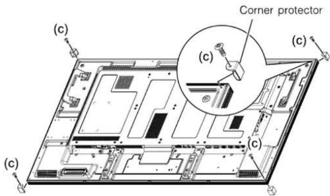
CONTROLS AND CONNECTORS : REMOTE CONTROL
text_image
POWER INPUT HDMI HOME DVD D-SUB OPTION DISPLAY PORT YPUP S-VIDEO VIDEO PICTURE MODE SIZE DISPLAY MENU AUDIO SET SET OUTPUT AUDIO INPUT VOL MUTE ON/OFF P/P INPUT CHANGE ON/OFF STILL CAPTURE| 1 | POWER^*1 | Turns the monitor ON and OFF. |
| 2 | INPUT^*2 | Selects the source. |
| 3 | PICTURE MODE | Selects the picture mode. See page 28. |
| 4 | DISPLAY | Provides resolution, source, audio input, picture size and color system mode information. |
| 5 | SET | Confirms your selection or save changes. |
| ▲▼-+ | Navigates through submenus and settings.▲: Up Button▼: Down Button-(Minus): - / Left Button+(Plus): + / Right Button | |
| 6 | AUTO SETUP^*3 | Displays the auto setup menu. |
| 7 | AUDIO INPUT | Selects the audio input according to the video input. See page 28. |
| 8 | PIP | ON/OFF: Switches the PIP or POP mode on/off.INPUT: Selects video to be displayed in the sub picture.CHANGE: Changes the main picture with the sub picture. |
| 9 | STILL | ON/OFF: Switches the still picture mode on/ off.CAPTURE: Captures the new picture. |
| 10 | SIZE | Selects the picture size. See page 28. |
| 11 | MENU | Opens the monitor's the OSD Menu or closes the OSD Menu. When the menu system is already open, pressing this button will select the previous submenu. |
| 12 | EXIT | Returns to a previous menu. |
| 13 | VOLUME(VOL) | VOL:- Decreases the sound volume.VOL+: Increases the sound volume. |
| 14 | MUTE | Turns on or off the mute function when the Menu is not displayed. |
*1 When the power indicator is not lit, no controls will work.
^*2 OPTION can be used when an expansion module is mounted on the option slot.
*3 Only D-SUB Input.
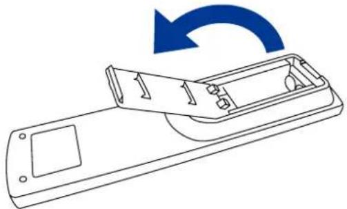
PREPARING THE REMOTE CONTROL
To use the remote control, insert the two dry batteries.
CAUTION
Do not use any other batteries other than those specified in this manual for the Remote Control. Do not insert old and new batteries together in the Remote Control. Make sure that the terminals match the "+" and "-" indications in the battery compartment. Burst batteries or the electrolyte from these batteries may cause stains, fire or injury.
① Unlock and pull up the battery cover as shown below.
natural_image
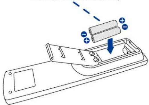
Line drawing of a remote control device with a blue circular arrow indicating rotation (no text or symbols)② Align and insert two AAA batteries according to their plus and minus ports (as indicated in the remote control). Battery x 2 (Not included)
natural_image
Diagram of a remote control panel with battery and battery cells, showing internal components and an open casing (no text or symbols)③ Replace the battery cover in the direction of the arrow and snap it back into place.

natural_image
Line drawing of a remote control device with a blue arrow indicating rotation (no text or symbols)NOTE
■ Replace with new batteries when the Remote Control does not work close to the monitor. Use AAA dry batteries.
■ Operate the Remote Control by pointing it toward the Remote Sensor on the monitor.
■ Other manufacturers remote control will not work with this monitor. Use the provided Remote Control ONLY.
■ Used batteries needed to follow the local rules to be discarded. (Suggestion: to dispose of used batteries please follow correct policy as per your local regulations.)
BASIC OPERATION
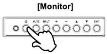
■ Turning the monitor ON
The monitor is turned On and the Power Indicator turns to Green when you press the POWER Button on the monitor or the Remote Control. The monitor is turned Off and the Power Indicator turns to Red when you press the POWER Button on the monitor or the Remote Control.
Press again to turn On the monitor.
NOTE
Even when using the power management mode or turning OFF the Power Switch, the monitor will consume a small amount of electricity. Disconnect the Power Cable from the power supply whenever the monitor is not in use or during the night, to avoid unnecessary power consumption.
text_image
[Monitor] MUTE INPUT + - EXF
text_image
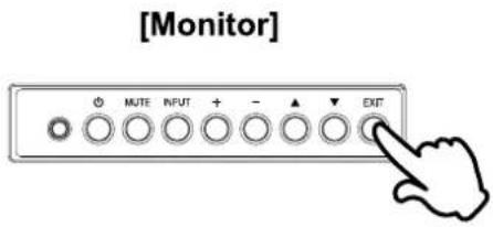
[Remote Control] HOLDEN OPEN SELECT SELECT SELECT SELECT SELECT SELECT SELECT SELECT SELECT SELECT SELECT SELECT SELECT SELECT SELECT SELECT SELECT SELECT SELECT SELECT SELECT SELECT SELECT SELECT SELECT SELECT SELECT SELECT SELECT SELECT SELECT SELECT SELECT SELECT SELECT SELECT SELECT SELECT SELECT SELECT SELECT SELECT SELECT SELECT SELECT SELECT SELECT SELECT SELECT SELECT CREATE CREATE CREATE CREATE CREATE CREATE CREATE CREATE CREATE CREATE CREATE CREATE CREATE CREATE CREATE CREATE CREATE CREATE CREATE CREATE CREATE CREATE CREATE CREATE CREATE CREATE CREATE CREATE CREATE CREATE CREATE CREATE CREATE CREATE CREATE CREATE■ Display the adjustment menu page
The menu page appears on the screen when you press the EXIT Button on the monitor or the MENU Button on the Remote Control.
The menu page disappears when you press the EXIT Button again.
text_image
[Monitor] MUTE INPUT + - ▲ EXIT[Remote Control]

text_image
POWER INPUT ON/OFF SELECT ON/OFF ON/OFF SELECT ON/OFF ON/OFF SELECT ON/OFF ON/OFF SELECT ON/OFF ON/OFF SELECT ON/OFF ON/OFF SELECT ON/OFF ON/OFF SELECT ON/OFF ON/OFF SELECT ON/OFF ON/OFF SELECT ON/OFF ON/OFF SELECT ON/OFF ON/OFF SELECT ON/OFF ON/OFF SELECT ON/OFF■ Move the cursor vertically
Select adjustment by pressing the ▲ / ▼ Button while the menu page is displayed on the screen.
[Monitor]
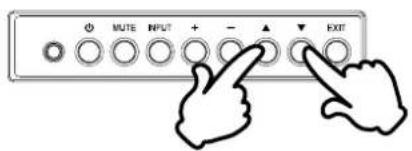
text_image
MUTE INPUT + - ▲ EXIT[Remote Control]
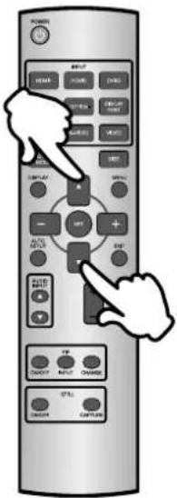
text_image
Diagram of a remote control with labeled buttons and hand gestures indicating navigation or function■ Move the cursor horizontally
Select menu or setting, or perform the adjustment by pressing the + / - Button while the menu page is displayed on the screen.
[Monitor]
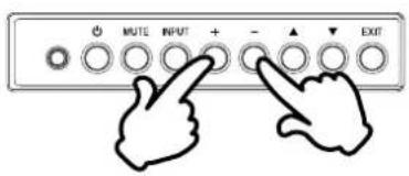
text_image
MUTE INPUT + - ▲ EXIT[Remote Control]
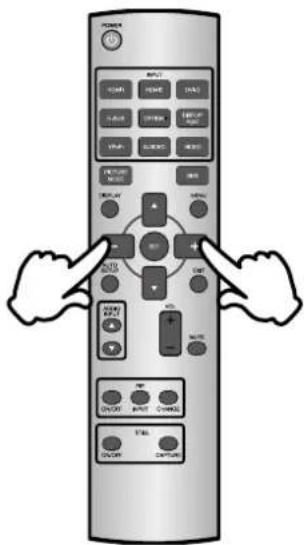
text_image
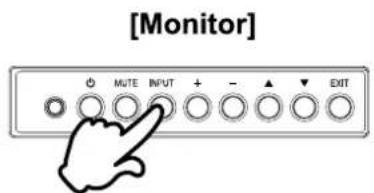
Diagram of a remote control with labeled buttons and function keys, showing hand gestures pointing to the right.■ Adjust the volume of sound
Press the + / - Button to adjust the volume of sound when the menu page is not displayed on the screen.
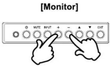
text_image
[Monitor] MUTE INPUT + - EXIT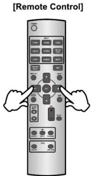
text_image
[Remote Control] POWER MINT ONION RETURN ON ONION RETURN ON RETURN ON RETURN ON RETURN ON RETURN ON RETURN ON RETURN ON RETURN ON RETURN ON RETURN ON RETURN ON RETURN ON RETURN ON RETURN ON RETURN ON RETURN ON RETURN ON RETURN ON RETURN ON RETURN ON RETURN ON RETURN ON RETURN ON RETURN ON RETURN ON RETURN ON RETURN ON RETURN ON RETURN ON RETURN ON RETURN ON RETURN ON RETURN ON RETURN ON■ Switch the input signal
This is activated when you successively press the INPUT Button on the monitor or INPUT Button on the Remote Control as follows:
text_image
[Monitor] MUTE INPUT + - ▲ EXIT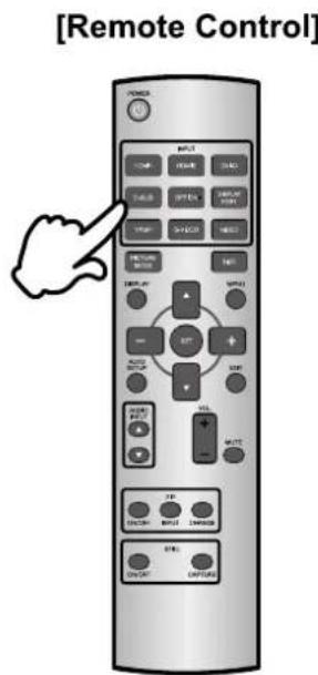
text_image
[Remote Control] POWER INPUT START LOAD TALE OFFSET ARRAY TIME CHANGE RESET RETURN ON/OFF EXP SELECT ON/OFF TITLE ON/OFF TITLE OFF SELECT ON/OFF TITLE ON/OFF TITLE OFF SELECT ON/OFF TITLE ON/OFF TITLE OFF SELECT ON/OFF TITLE ON/OFF TITLECONNECTING YOUR MONITOR
① Ensure that both the computer and the monitor are switched off.
②Connect the computer to the monitor with the signal cable.
③Connect the Power Cable to the monitor first and then to the power supply.
④Turn on your monitor (Main Power Switch and Power Switch) and computer.
NOTE
■ The signal cables used for connecting the computer and monitor may vary with the type of computer used. An incorrect connection may cause serious damage to both the monitor and the computer. The cable supplied with the monitor is for a standard connector. If a special cable is required please contact your local iiyama dealer or regional iiyama office.
■ For connection to Macintosh computers, contact your local iiyama dealer or regional iiyama office for a suitable adaptor.
■ Make sure you tighten the finger screws at each end of the Signal Cable.
[Example of Connection]
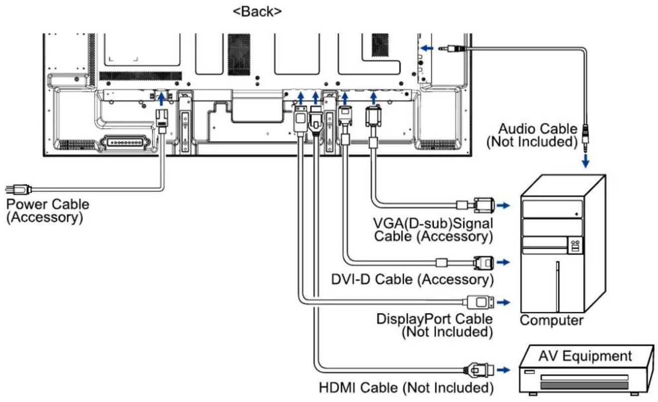
flowchart
graph TD
    A["Computer"] --> B["AV Equipment"]
    B --> C["HDMI Cable (Not Included)"]
    C --> D["DisplayPort Cable (Not Included)"]
    D --> E["DVI-D Cable (Accessory)"]
    E --> F["VGA(D-sub)Signal Cable (Accessory)"]
    F --> G["Power Cable (Accessory)"]
    G --> H["<Back>"]
    H --> I["Audio Cable (Not Included)"]
[ Connection example with the peripheral device ]
CAUTION
Turn off the power switch and unplug the monitor and peripherals before connection to avoid electric shock or damage.
NOTE
■ Refer to the user manual of peripherals at the same time.
■ Ensure you have the necessary cables as required.
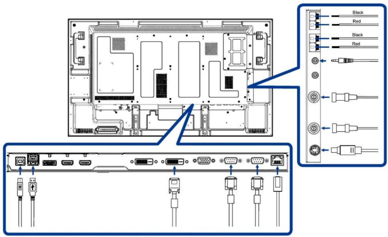
text_image
Diagram of a computer rear panel with labeled connectors and ports, showing internal structure and external wiring connections.[PREVENTION OF DISCONNECTION OF HDMI CABLE]
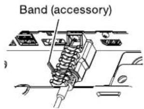
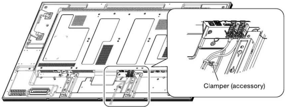
For connecting an HDMI cable to the connector on the monitor, it is recommended to secure the cable using an accessory clamper to prevent accidental disconnection.
- Connect an HDMI cable to the connector on the monitor.
- Secure the HDMI cable using a clamper (accessory) and a band (accessory).
① Remove the screw from the monitor.
②Attach the clamper to the monitor using the screw you have removed in step ①.
③ Secure the HDMI cable and the clamper using the band.
NOTE
The band isn't reusable. The monitor comes with 2 spare bands.
To replace the band, cut and remove the existing band and attach a new one of the same shape (commercially available, 2.5 mm in width and approximately 100 mm in length).
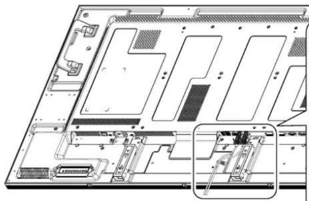
natural_image
Technical diagram of an electronic device rear panel with internal components and a close-up inset showing internal structure (no text or symbols)①
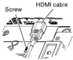
text_image
Screw HDMI cable②

text_image
Clamper (accessory)③
text_image
Band (accessory)- Secure the HDMI cable using a clamper (accessory) and a band (accessory).
text_image
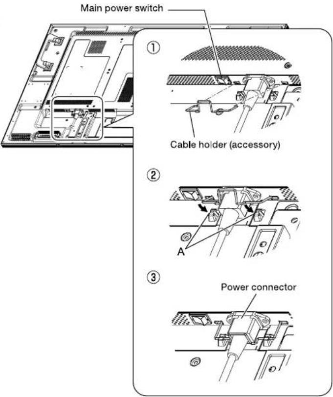
Clamper (accessory)[CONNECTING THE POWER SOURCE]
Before making connections
Check that the main power switch is off.
NOTE
Please refer to "Important Safety Instructions" and "Installation, Ergonomics, Care, and Service" in this manual for proper selection of the AC power cord. Use the clamper to prevent accidental disconnection of the power cord.
- Insert the power connector of the power cord fully and firmly into the AC IN connector of the monitor.
- Secure the power connector using the cable holder (accessory).
WARNING
Don't insert the cable holder into the power outlet socket. Doing so may cause electric shock.
① Fit both ends of the cable holder to the monitor.
② Engage the cable holder in Parts A.
③ Secure the power connector with the cable holder.
- Secure the power cord using the clamper (accessory).
- Insert the power plug into the power outlet socket.
■ Fully insert the prongs into the power outlet socket. Loose connection may cause noise.
- Don't plug and unplug the power cord repeatedly in a short time of period.
text_image
Main power switch ① Cable holder (accessory) ② A ③ Power connector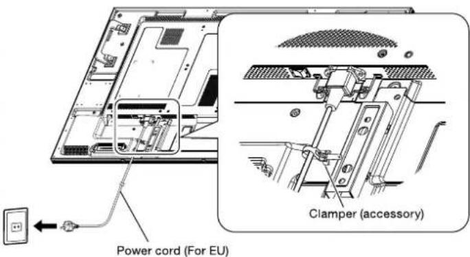
text_image
Power cord (For EU) Clamper (accessory)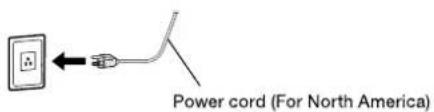
text_image
Power cord (For North America)COMPUTER SETTING
■ Signal Timing
Change to the desired signal timing listed on page 55 : COMPLIANT TIMING.
■ Windows XP/Vista/7/8 Plug & Play
The iiyama LCD monitor complies with DDC2B of VESA standard. The Plug & Play function runs on Windows XP/Vista/7/8 by connecting the monitor to DDC2B compliant computer with the Signal Cable supplied.
For installation on Windows XP: The monitor Information File for iiyama monitors may be necessary for your computer and obtained via the Internet, using the address:
http://www.iiyama.com
NOTE
■ Monitor Drivers are not required in most cases for Macintosh or Unix operating systems. For further information, please contact your computer dealer first for advice.
OPERATING THE MONITOR
To create the best picture, your iiyama LCD monitor has been preset at the factory with the COMPLIANT TIMING shown on page 55. You are also able to adjust the picture by following the button operation shown below. For more detailed adjustments, see page 47 for SCREEN ADJUSTMENTS.
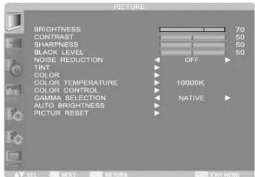
① Press the MENU Button (Remote Control) or EXIT Button (Back Controller) to start the On Screen Display feature. There are additional Menu items which can be switched by using the ▲ / ▼ Buttons.
text_image
PICTURE BRIGHTNESS CONTRAST SHARPNESS BLACK LEVEL NOISE REDUCTION TINT COLOR COLOR TEMPERATURE COLOR CONTROL GAMMA SELECTION AUTO BRIGHTNESS PICTUR RESET 70 50 50 50 OFF 10000K NATIVE② Select the Menu item of the adjustment you want to make. Press the SET Button(Remote Control) or INPUT Button (Back Controller) and enter the menu page. Then, use the ▲ / ▼ Buttons to highlight the desired adjustment item.
③ Press the SET Button(Remote Control) or INPUT Button (Back Controller) again. Use the + / - Buttons to make the appropriate adjustment or setting.
④ Press the EXIT Button to leave the menu, and the settings you just made would be automatically saved.
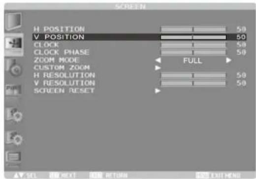
For example, to correct for vertical position, select Menu item of Screen. Then, select "V POSITION" by using the ▲ / ▼ Buttons.
Use the + / - Buttons to change the vertical position settings. The vertical position of the overall display should be changing accordingly while you are doing this.
text_image
H POSITION V POSITION CLOCK CLOCK PHASE ZOOM MODE CUSTOM ZOOM H RESOLUTION V RESOLUTION SCREEN RESET 50 50 50 FULL 50 50 AV SEL 100 NEXT 100 RETURN 100 EXIT MARGINPress the EXIT Button lastly, it ends, all changes are saved in the memory.
NOTE
■ The EXIT Button can be used to return previous menu item.
■ Any changes are automatically saved in the memory when the On Screen Display disappears. Turning off the power should be avoided while using the Menu.
■ Adjustments for Image Position, Clock and Phase are saved for each signal timing. Except for these adjustments, all other adjustments have only one setting which applies to all signal timings.
[CONTROL LOCK MODE]
● Back Controller Button:
Pressing and holding the ▲ and ▼ buttons for about 3 seconds when Menu is not displayed, will lock/unlock the Back Controller Button Lock function.

* Available for Remote Control only.
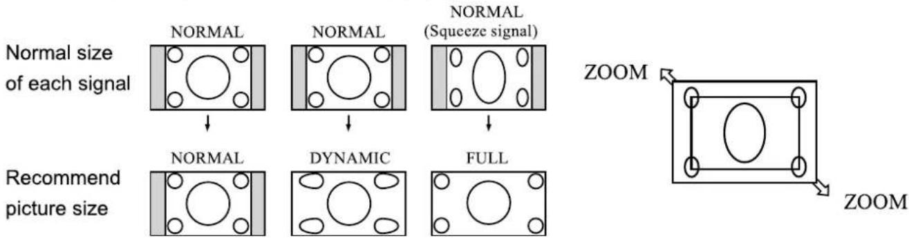
● Picture Size:
Press the SIZE button when Menu is not displayed.
flowchart
graph TD
    A["Normal size of each signal"] --> B["NORMAL"]
    B --> C["NORMAL"]
    C --> D["NORMAL (Squeeze signal)"]
    D --> E["NORMAL"]
    E --> F["DYNAMIC"]
    F --> G["FULL"]
    G --> H["ZOOM"]
    H --> I["ZOOM"]
    J["Recommend picture size"] --> K["NORMAL"]
    K --> L["DYNAMIC"]
    L --> M["FULL"]
NORMAL: Images supplied from external devices such as PC and DVD fit the screen, keeping their original aspect ratio.
FULL: Images are displayed on the entire screen.
DYNAMIC: 4:3 images are enlarged on the entire screen with non-linearity. (Round images may be cut when enlarged.)
CUSTOM (ZOOM): You can enlarge the displayed images beyond the active display area. The portions of the image out of the display area aren't visible.
REAL: Images are displayed in their original sizes.
- "DYNAMIC" can be selected for video input (YPbPr, VIDEO, and S-VIDEO).
● Picture Mode:
Press the PICTURE MODE button when Menu is not displayed.
HIGHBRIGHT: The brightness is maximized.
STANDARD: Factory default setting.
sRGB: Suitable for color matching with sRGB-compliant devices.
CINEMA: Suitable for viewing movies.
- "sRGB" can be selected for computer input (HDMI1, HDMI2, DVI-D, D-SUB and DISPLAYPORT).
- "CINEMA" can be selected for video input (HDMI1, HDMI2, YPbPr, VIDEO and S-VIDEO).
● Audio Input Change:
Press the AUDIO INPUT ▲ / ▼ buttons when Menu is not displayed.
Note that the selectable audio inputs vary depending on the currently selected video signal input.
| Selection of the video signal input | Operation | |
| HDMI1 or HDMI2 | 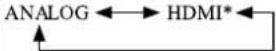 | |
| DVI-D | ANALOG only | |
| D-SUB | ANALOG only | |
| DISPLAYPORT | 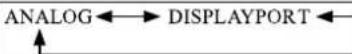 | |
| YPbPr | ANALOG only | |
| S-VIDEO | ANALOG only | |
| VIDEO | ANALOG only | |
* The audio of HDMI1 or HDMI2 being selected is output as the HDMI audio.
ADJUSTMENT MENU CONTENTS
PICTURE
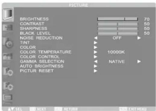
text_image
PICTURE BRIGHTNESS 70 CONTRAST 50 SHARPNESS 50 BLACK LEVEL 50 NOISE REDUCTION OFF TINT COLOR 10000K COLOR TEMPERATURE COLOR CONTROL GAMMA SELECTION NATIVE AUTO BRIGHTNESS PICTUR RESET| Adjustment Item | Problem / Option | Button to Press | ||
| BRIGHTNESS^*1 | Too darkToo bright | 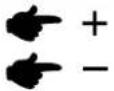 | ||
| CONTRAST^*2 | Too dullToo intense | 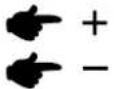 | ||
| SHARPNESS | Too softToo sharp | 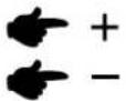 | ||
| NOTE If you increase the sharpness setting value too much, lines may appear double. In such a case, decrease the sharpness setting value. | ||||
| BLACK LEVEL^*2 | Brightness of back light is reduced.  | |||
| NOISE REDUCTION^*2,3 | OFF | Noise Reduction is turned off. | ||
| LOW | Electronic image noise caused by different media players is reduced. | |||
| MIDDLE | Electronic image noise caused by different media players is reduced. | |||
| HIGH | Electronic image noise caused by different media players is reduced. | |||
| TINT^*2 | TINT | PurplishGreenish  | ||
| RED HUE | You can set the Colours. 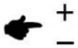 | |||
| MAGENTA HUE | ||||
| BLUE HUE | ||||
| CYAN HUE | ||||
| GREEN HUE | ||||
| YELLOW HUE | ||||
| COLOR^*2 | COLOR | Too weakToo strong 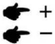 | ||
| RED HUE | You can set the Colours.  | |||
| MAGENTA HUE | ||||
| BLUE HUE | ||||
| CYAN HUE | ||||
| GREEN HUE | ||||
| YELLOW HUE | ||||
PICTURE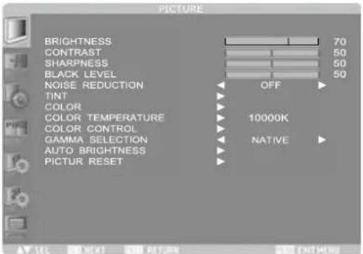 | |||
| Adjustment Item | Problem / Option Button to Press | ||
| COLOR TEMPERATURE *2 | ReddishBluish + - | ||
| COLOR CONTROL*2 | RED | Too weakToo strong + - | |
| GREEN | |||
| BLUE | |||
| GAMMA SELECTION | Select the gamma mode.NATIVE / S GAMMA / 2.2 / 2.4 / OPTION / PROGRAMMABLE.PROGRAMMABLE can change the GAMMA characteristic curve via a computer. Contact your dealer for further details.NOTE GAMMA is fixed to 2.2 in the sRGB picture mode. When PROGRAMMABLE has been selected, the setting for color temperature is fixed at 10,000 K (NATIVE). | ||
| AUTO BRIGHTNESS*4 | AUTO BRIGHTNESS | OFF | AUTO BRIGHTNESS is turned off. |
| LOCAL | The AUTO BRIGHTNESS function is enabled and you can adjust [CONTROL] and subsequent items individually. | ||
| REMOTE | The AUTO BRIGHTNESS function is enabled. In addition, the monitor enters the intercommunication mode where multiple monitors are controlled collectively. (See page 45) | ||
| AUTO | The settings of AUTO BRIGHTNESS are adjusted automatically.NOTE When you select AUTO, you cannot adjust any other items than [CONTROL] individually. | ||
| CONTROL | PRIMARY | Select this setting to configure the monitor as Master when controlling multiple monitors collectively. | |
| SECONDARY | Select this setting to use the monitor alone or to configure the monitor as Slave when controlling multiple monitors collectively. | ||
| AUTO BRIGHTNESS*4 | LIGHT FROM BACK*5 | When a light source such as a light and a window is behind the monitor, the rear sensor takes precedence. | |
| YES | Select this setting when there is a light source such lighting equipment and a window behind the monitor. | ||
| NO | Select this setting when there is no light source such lighting equipment and a window behind the monitor. | ||
| BACK WALL*5 | Select the following settings according to the distance between the rear of the monitor and the wall or window. | ||
| FAR | The distance is 5 meters or longer. | ||
| NEAR | The distance is 5 meters or shorter. | ||
| FRONT SENSOR | ON | Select ON for normal use. | |
| OFF | Select this setting when the sensor on the front panel is shielded. | ||
| REAR SENSOR | ON | Select ON for normal use. | |
| OFF | Select this setting when the sensor on the rear panel is shielded. | ||
| SATURATION | ON | The image saturation is adjusted depending on the ambient light. | |
| OFF | SATURATION is turned off. | ||
| VIDEO DETECT | ON | The screen brightness varies depending on what are displayed on the screen to reduce power consumption of the monitor. | |
| OFF | VIDEO DETECT is turned off. | ||
| PICTURE RESET | NO | Return to Menu. | |
| YES | Reset all the PICTURE settings to the factory defaults. | ||
*1 Adjust the Brightness when you are using the monitor in a dark room and feel the screen is too bright. BRIGHTNESS is disabled when BRIGHTNESS of SCREEN SAVER in the CONFIGURATION1 menu is active.
*2 This adjustment doesn't work in the sRGB picture mode.
^3 This function doesn't work on D-SUB input.
*4 This adjustment doesn't work in the sRGB or CINEMA picture mode.
^5 This function is enabled only when REAR SENSOR is ON.
SCREEN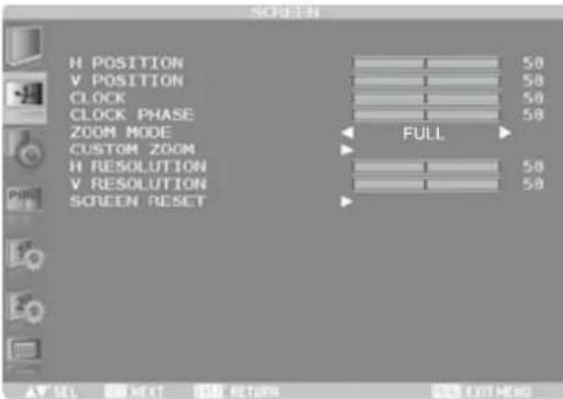 | ||
| Adjustment Item | Problem / Option | Button to Press |
| H POSITION | Too far to the leftToo far to the right | + - + |
| V POSITION | Too lowToo high | + - + - + |
| CLOCK* | Too narrowToo wide | + - + - + |
| CLOCK PHASE* | To correct flickering text or lines | + - + - + |
| ZOOM MODE | FULL | The image is stretched to full the screen regardless of its aspect ratio. |
| NORMAL | The image is stretched vertically to the full height of the screen while keeping the aspect ratio. | |
| DYNAMIC | The image is stretched to full the screen with different magnif cations at the screen center and the screen edges. | |
| CUSTOM | Stretch the image horizontally and vertically as you desire using the CUSTOM ZOOM setting. | |
| REAL | The image is displayed without being stretched or reduced. | |
| NOTE The DYNAMIC mode displays images having the 16:9 aspect ratio, such as those with 1920 x 1080 resolution, in the same way as in the FULL mode. | ||
| CUSTOM ZOOM | CUSTOM ZOOM becomes selectable when you set ZOOM MODE to CUSTOM. | |
| ZOOM | Expand the horizontal and vertical sizes simultaneously. | |
| H ZOOM | Expand the horizontal size only. | |
| V ZOOM | Expand the vertical size only. | |
| H POSITION | Too far to the leftToo far to the rightToo far to the rightToo lowToo highToo highToo lowToo highToo highToo highToo highToo highToo highToo highToo highToo highToo highToo highToo highToo highToo highToo highToo highToo highToo highToo highToo highToo highToo highToo highToo highToo highToo highToo highToo highToo highToo highToo highToo highToo highToo highToo highToo highToo highToo highToo highToo highToo highToo highToo highToo highToo highToo highToo highToo highToo highToo highToo hToo highToo highToo highToo highToo highToo highToo highToo highToo highToo highToo highToo highToo highToo highToo highToo highToo highToo highToo highToo highToo highToo highToo highToo highToo highToo highToo highToo highToo highToo highToo highToo highToo highToo highToo highToo highToo highToo highToo highToo highToo highToo highToo highToo highToo highToo highToo highToo highToo highToo lowToo highToo highToo highToo highToo highToo highToo highToo highToo highToo highToo highToo highToo highToo highToo highToo highToo highToo highToo highToo highToo highToo highToo highToo highToo highToo highToo highToo highToo highToo highToo highToo highToo highToo highToo highToo highToo highToo highToo highToo highToo highToo highToo highToo highToo highToo highToo hToo highToo highToo hToo highToo hToo highToo hToo highToo hToo highToo hToo highToo hToo highToo hToo highToo hToo highToo hToo highToo hToo highToo hToo highToo hToo highToo hToo highToo hToo highToo hToo highToo hToo highToo hToo highToo hToo highToo hToo highToo hToo highToo hToo highToo hToo highToo hToo highToo hToo highToo hToo highToo highToo hToo highToo hToo highToo hToo highToo hToo highToo hToo highToo hToo highToo hToo highToo hToo highToo hToo highToo hToo highToo hToo highToo hToo highToo hToo highToo hToo highToo hToo highToo hToo highToo hToo highToo hToo highToo hToo highToo hToo highToo hToo highToo hToo highToo hToo hToo highToo hToo hToo highToo hToo hToo highToo hToo hToo highToo hToo hToo highToo hToo hToo highToo hToo hToo highToo hToo hToo highToo hToo hToo highToo hToo hToo highToo hToo hToo highToo hToo hToo highToo hToo hToo highToo hToo hToo highToo hToo hToo highToo hToo hToo highToo hToo hToo hToo highToo hToo hToo hToo hToo hToo hToo hToo hToo hToo hToo hToo hToo hToo hToo hToo hToo hToo hToo hToo hToo hToo hToo hToo hToo hToo hToo hToo hToo hToo hToo hToo hToo hToo hToo hToo hToo hToo hToo hToo hToo hToo hToo hToo hToo hToo hToo hToo hToo hToo hToo uToo hToo hToo hToo hToo hToo hToo hToo hToo hToo hToo hToo hToo hToo hToo hToo hToo hToo hToo hToo hToo hToo hToo hToo hToo hToo hToo hToo hToo hToo hToo hToo hToo hToo hToo hToo hToo hToo hToo hToo hToo hToo hToo hToo hToo hToo hToo hToo hToo hToo tToo hToo hToo hToo hToo hToo hToo hToo hToo hToo hToo hToo hToo hToo hToo hToo hToo hToo hToo hToo hToo hToo hToo hToo hToo hToo hToo hToo hToo hToo hToo hToo hToo hToo hToo hToo hToo hToo hToo hToo hToo hToo hToo hToo hToo hToo hToo hToo hToo hToo oToo hToo hToo hToo hToo hToo hToo hToo hToo hToo hToo hToo hToo hToo hToo hToo hToo hToo hToo hToo hToo hToo hToo hToo hToo hToo hToo hToo hToo hToo hToo hToo hToo hToo hToo hToo hToo hToo hToo hToo hToo hToo hToo hToo hToo hToo hToo hToo hToo hToo aToo hToo aToo aToo aToo aToo aToo aToo aToo aToo aToo aToo aToo aToo aToo aToo aToo aToo aToo aToo aToo aToo aToo aToo aToo aToo aToo aToo aToo aToo aToo aToo aToo aToo aToo aToo aToo aToo aToo aToo aToo aToo aToo aToo aToo aToo aToo aToo aToo aToo aToo aTooaToo aToo aToo aToo aToo aToo aToo aToo aToo aToo aToo aToo aToo aToo aToo aToo aToo aToo aToo aToo aToo aToo aToo aToo aToo aToo aToo aToo aToo aToo aToo aToo aToo aToo aToo aToo aToo aToo aToo aToo aToo aToo aToo aToo aToo aToo aToo aToo aToo aToo,aToo aToo aToo aToo aToo aToo aToo aToo aToo aToo aToo aToo aToo aToo aToo aToo aToo aToo aToo aToo aToo aToo aToo aToo aToo aToo aToo aToo aToo aToo aToo aToo aToo aToo aToo aToo aToo aToo aToo aToo aToo aToo aToo aToo aToo aToo aToo aToo aToo aToo-aToo aToo aToo aToo aToo aToo aToo aToo aToo aToo aToo aToo aToo aToo aToo aToo aToo aToo aToo aToo aToo aToo aToo aToo aToo aToo aToo aToo aToo aToo aToo aToo aToo aToo aToo aToo aToo aToo aToo aToo aToo aToo aToo aToo aToo aToo aToo aToo aToo aToo | |
| V RESOLUTION* | Use this setting when AUTO SETUP and AUTO ADJUST cannot obtain the vertical resolution of the input signal. | |
| SCREEN RESET | NO | Return to Menu. |
| YES | Reset all the SCREEN settings to the factory defaults. | |
* Only D-SUB input.
AUDIO 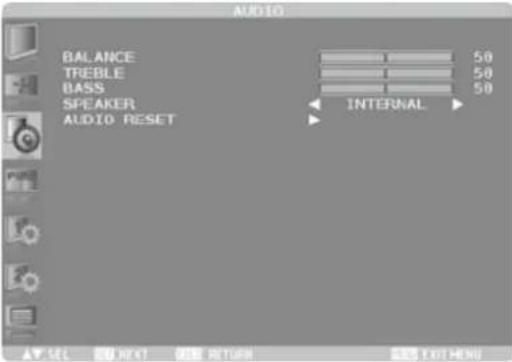 | ||
| Adjustment Item | Problem / Option Button to Press | |
| BALANCE | Left side speaker louderRight side speaker louder | |
| TREBLE | Too weakToo strong | |
| BASS | Too weakToo strong | |
| SPEAKER | INTERNAL | Select the Internal Speaker. |
| EXTERNAL | Select the External Speaker. | |
| AUDIO RESET | NO | Return to Menu. |
| YES | Reset all the SOUND settings to the factory defaults. | |
PIP* 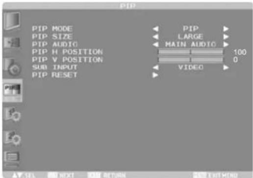 | |||
| Adjustment Item | Problem / Option Button to Press | ||
| PIP MODE | PIP POP SBS ASPECT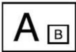 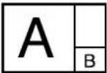 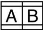 | ||
SBS FULL OFF  | |||
| PIP SIZE | SMALL | Reduce the size of the Sub screen. | |
| MIDDLE | Middle the size of the Sub screen. | ||
| LARGE | Increase the size of the Sub screen. | ||
| PIP AUDIO | MAIN AUDIO | Select the main audio. | |
| PIP AUDIO | Select the PIP audio. | ||
| PIP H POSITION | Move the horizontal position of the Sub screen.  | ||
| PIP V POSITION | Move the vertical position of the Sub screen.  | ||
| SUB INPUT | Select from the input signals HDMI, DVI-D, D-SUB, YPbPr, S-VIDEO and VIDEO of the Sub screen. | ||
| PIP RESET | NO | Return to Menu. | |
| YES | Reset all the PIP settings to the factory defaults. | ||
* PIP = Picture in Picture POP = Picture on Picture SBS = Side by Side With this function, you can display two different picture. PIP, POP support details, See page 56 "PIP, POP Support Screen Table".
CONFIGURATION1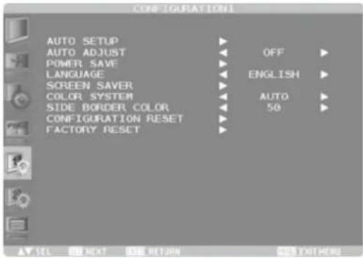 | |||||
| Adjustment Item | Problem / Option Button to Press | ||||
| AUTO SETUP*1 | The screen size, horizontal/vertical position, clock, clock phase, and input signal level are automatically adjusted. | ||||
| AUTO ADJUST*1 | ON | The horizontal position, vertical position, and clock phase are automatically adjusted at the time of the timing switching. | |||
| OFF | Return to Menu. | ||||
| POWER SAVE | When the power saver in the OSD menu is turned ON, the power management function works. | ||||
| RGB | When the sync signal of computer input (HDMI1, HDMI2, DVI-D, D-SUB, or DISPLAYPORT) is terminated, the monitor will be in the sleep mode in several seconds. | ||||
| VIDEO | When the sync signal of video input (YPbPr, S-VIDEO, or VIDEO) is terminated, the monitor will be in the sleep mode in approximately 10 minutes. | ||||
| LANGUAGE | English | English | Nederlands | Dutch | |
| Français | French | Polski | Polish | ||
| Deutsch | German | Русский | Russian | ||
| SCREEN SAVER | GAMMA | ON | The Gamma mode where image persistence is difficult to occur is used. | ||
| OFF | GAMMA is turned off. | ||||
| COOLING FAN | AUTO | The built-in fan automatically starts running according to the operating temperature. | |||
| ON | The cooling fan always runs. | ||||
| BRIGHTNESS | ON | The brightness decreases. | |||
| OFF | BRIGHTNESS is turned off. | ||||
| CONFIGURATION1 | 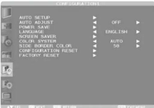 | ||||
| Adjustment Item | Problem / Option Button to Press | ||||
| SCREEN SAVER | MOTION*2 | ON | The screen slightly moves horizontally and vertically at regular intervals to reduce the effect of the image persistence. 10-900s | ||
| OFF | MOTION is turned off. | ||||
When you select a time period in the MOTION setting, the monitor enlarges the image and moves it horizontally and vertically. The portions of the image out of the display area aren't visible. To make the entire image visible all the time, arrange it to fit within 90% of the screen area at the center. 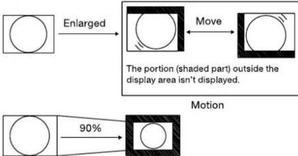 | |||||
| COLOR SYSTEM*3 | AUTO | NTSC, PAL, SECAM, PAL-60 or 4.43 NTSC is automatically selected. | |||
| NTSC | Select the NTSC. | ||||
| PAL | Select the PAL. | ||||
| SECAM | Select the SECAM. | ||||
| 4.43NTSC | Select the 4.43NTSC. | ||||
| PAL-60 | Select the PAL-60. | ||||
| SIDE BORDER COLOR | Adjust the brightness of the area where no images are displayed when a 4:3 image is displayed in the NORMAL mode in the ZOOM MODE or the POP or other modes in the PIP MODE. | ||||
| OFF | SIDE BORDER COLOR is turned off. (Black) | ||||
| 50 | Brighten the screen brightness. (Gray) | ||||
| 100 | Brighter than "50" the brightness of the screen. (White) | ||||
| CONFIGURATION RESET | NO | Return to Menu. | |||
| YES | Reset all the CONFIGURATION1 and CONFIGURATION2 settings to the factory defaults. | ||||
| NOTE The LANGUAGE, MONITOR ID, SCHEDULE, and DATE AND TIME settings aren't reset. | |||||
CONFIGURATION1 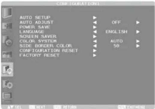 | |||||
| Adjustment Item | Problem / Option Button to Press | ||||
| FACTORY RESET | NO | Return to Menu. | |||
| YES | Reset all the PICTURE, SCREEN, AUDIO, CONFIGURATION1, CONFIGURATION2, and ADVANCED OPTION settings to the factory defaults. | ||||
| NOTE The LANGUAGE, CONTROL TIME OUT, MONITOR ID, SCHEDULE, and DATE AND TIME aren't reset. | |||||
*1 Only D-SUB input.
*2 MOTION is disabled when TILING in the ADVANCED OPTION menu is active.
*3 Only S-VIDEO and VIDEO inputs.
CONFIGURATION2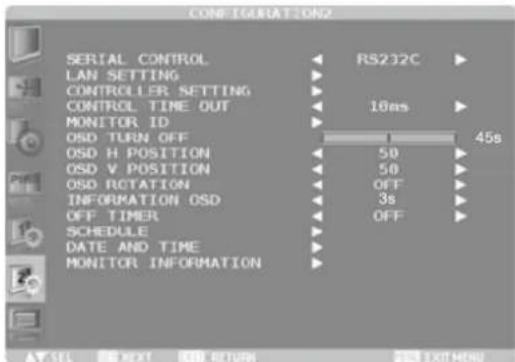 | |||
| Adjustment Item | Problem / Option Button to Press | ||
| SERIAL CONTROL | RS-232C | Select the RS-232C. | |
| LAN | Select the LAN. | ||
| LAN SETTING* | DHCPCLIENT | ON | Select whether to use DHCP client or not. |
| OFF | DHCP CLIENT is turned off. | ||
| IP ADDRESS | When DHCP CLIENT is OFF, set the IP address of the monitor. When DHCP CLIENT is ON, you can check the value set by the DHCP server. | ||
| SUBNETMASK | When DHCP CLIENT is OFF, set the gateway mask. Set it to 255.255.255.0 for normal use. When DHCP CLIENT is ON, you can check the value set by the DHCP server. | ||
| DEFAULTGATEWAY | When DHCP CLIENT is OFF, set the IP address of the gateway router to externally connect the local area including the monitor.When DHCP CLIENT is ON, you can check the value set by the DHCP server. | ||
| PORT | The port number (60822) of the monitor is displayed. | ||
| RESET | LAN settings are reset. | ||
| CONTROLLER SETTING* | CONTROLLERIP | Set the IP address of the control processor. | |
| PORTNUMBER | Set the port number used for communication. | ||
| IP ID | Set the IP identification number. | ||
| CONTROL TIME OUT | When using remote control, the timeout for transmission intervals among codes within the control command can be set.10ms / 2s / 30s | ||
| MONITOR ID | Set ID to the Monitor.1-26 | ||
| OSD TURN OFF | The OSD control menu will stay on as long as it is used. 5 - 120 seconds + - | ||
* This function is enabled only when you selected "LAN" in SERIAL CONTROL.
CONFIGURATION2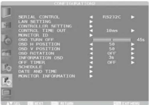 | |||
| Adjustment Item | Problem / Option | Button to Press | |
| OSD H POSITION | OSD is too leftOSD is too right | + - | |
| OSD V POSITION | OSD is too lowOSD is too high | + - | |
| OSD ROTATION | OFFabc90L90 degree rotation | H MIRRORHorizontally rotated180180 degree rotation | V MIRRORSpcVertically rotated90R270 degree rotation |
| INFORMATION OSD | Enable and disable the information OSD display.OFF, 3 - 10 secondsNOTE The information OSD display shows a message when the input source is switched. | ||
| OFF TIMER | Select the OFF TIMER mode.OFF, 1 - 24 hoursNOTE When OFF TIMER is enabled, the SCHEDULE settings (see page 44) will be disabled. | ||
| SCHEDULE | You can program the LCD display operation schedules. (See page 44) | ||
| DATE AND TIME | Adjust the current date and time for the internal clock. You must set this item when using SCHEDULE. After competing the setting, be sure to press the SET button (Remote Control) or INPUT button (Back Controller). YEAR / MONTH / DAY / HOUR / MINUTE / DAYLIGHT SAVING TIME | ||
| MONITOR INFORMATION | The model name and the serial number of your monitor are displayed. The MAC address of LAN is displayed. | ||
ADVANCED OPTION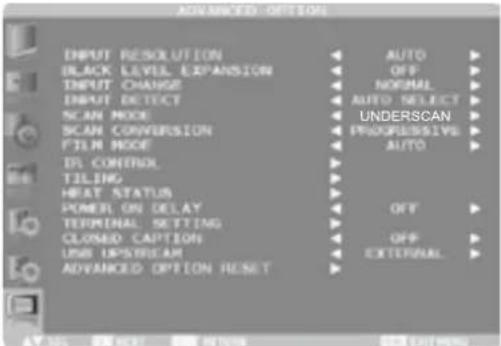 | ||
| Adjustment Item | Problem / Option Button to Press | |
| INPUT RESOLUTION*1 | If the monitor fails to recognize the input signal resolution correctly, you can select a proper resolution manually. Only when a signal having a resolution close to any of the following values from three groups, the values in the most appropriate group are selectable. | |
| Group 1 | AUTO, 1024 x 768, 1280 x 768, 1360 x 768, 1366 x 768 | |
| Group 2 | AUTO, 1400 x 1050, 1680 x 1050 | |
| Group 3 | AUTO, 1600 x 1200, 1920 x 1200 | |
| BLACK LEVEL EXPANSION*2 | OFF | BLACK LEVEL EXPANSION is turned off. |
| SOFT | Lower the black level. | |
| HARD | Lower than the black level "SOFT". | |
| INPUT CHANGE | NORMAL | Normal switching time. |
| QUICK | Quick switching time. | |
| NOTE When you select QUICK, slight noise may appear. | ||
| INPUT DETECT | OFF | INPUT DETECT is turned off. |
| AUTO SELECT | The target video inputs are DVI-D and D-SUB. When the currently selected input signal is lost, this function checks whether the signal is present at the other input. When present, the other input is automatically selected. If no signal is present at both inputs for five seconds, the monitor enters the sleep mode. The priority of the input signal is as follows: DVI-D > D-SUBNOTE You cannot select other inputs than DVI-D and D-SUB. | |
| VIDEO SELECT | The target video inputs are HDMI1, S-VIDEO, VIDEO, and D-SUB.When the HDMI1, S-VIDEO, or VIDEO input is detected, the detected input is automatically selected.When the video signal being displayed is lost, the D-SUB input is automatically selected.The priority of the input signal is as follows:HDMI1 >VIDEO >S-VIDEONOTE You cannot select HDMI2, DVI-D and DISPLAYPORT. | |
| SCAN MODE*3 | Select the image display area. | |
| OVERSCAN | About 95% of the input image is displayed. | |
| UNDERSCAN | Almost 100% of the input image is displayed. | |
| ADVANCED OPTION | 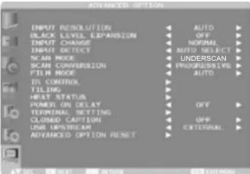 | ||
| Adjustment Item | Problem / Option Button to Press | ||
| SCAN CONVERSION*3,4 | Select the IP conversion mode. | ||
| PROGRESSIVE | Interlace signals are converted into progressive signals. Select this setting for normal cases. | ||
| INTERLACE | Interlace signals are displayed without being converted. Though this setting is suitable for motion images, still images aren't displayed properly. | ||
| FILM MODE*3,4 | OFF | FILM MODE is turned off. | |
| AUTO | Images of 24 frames per second are detected, subjected to interpolation, and then displayed. | ||
| NOTE When FILM MODE is AUTO, set SCAN CONVERSION to PROGRESSIVE. | |||
| IR CONTROL | Lock the remote control. | ||
| NORMAL | All the remote control operations are enabled. | ||
| PRIMARY | The first monitors of those multiconnected via RS-232C is designated as PRIMARY. | ||
| SECONDARY | The monitors other than the first one multi-connected via RS-232C are designated as SECONDARY. | ||
| LOCK | All the remote control operations are disabled. | ||
| NOTE When you hold down the DISPLAY button on the remote control for at least 5 seconds, the NORMAL mode is activated. | |||
| TILING | TILING is a function to divide or enlarge images and display them across multiple screens. You can divide an input video up to five pieces horizontally and vertically and display them on a single large screen comprised of up to 25 (5 x 5) monitors tiled together. | ||
| H MONITORS | Sets the number of displays used in the horizontal position. | ||
| V MONITORS | Sets the number of displays used in the vertical position. | ||
| POSITION | Select the area you want to enlarge. | ||
| FRAME COMP. | ON | When displaying an image across multiple monitors, you can select the mode to compensate for the bezel widths for smooth and natural display. | |
| OFF | FRAME COMP. is turned off. | ||
| ENABLE | ON | The image in the selected area is enlarged on the screen. | |
| OFF | ENABLE is turned off. | ||
ADVANCED OPTION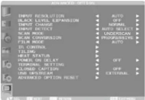 | |||
| Adjustment Item | Problem / Option Button to Press | ||
| HEAT STATUS | The statuses of the cooling fan, brightness, and internal temperature are displayed. NOTE The cooling fan starts running according to the operating temperature or when COOLING FAN is ON in the SCREEN SAVER menu. When the operating temperature substantially exceeds the operation guaranteed range, the message "TEMPERATURE WARNING" is displayed on the screen. | ||
| POWER ON DELAY | Adjust the delayed time until the power-on mode is activated at the time of recovery from the sleep mode or power-on.OFF, 2 - 50 seconds | ||
| TERMINAL SETTING | You can select the mode to display the HDMI1, HDMI2, or DVI-D signal according to their signal format depending on their source device. | ||
| HDMI SIGNAL 1/2 | FULL | Select FULL when displaying the signal that uses all 256 levels (from level 0 to 255). This mode is used primarily when input comes from a computer. | |
| LIMITED | Select LIMITED when displaying the signal that uses 16 to 235 levels of 256 levels for each of R, G, and B. This mode is used primarily when input comes from a video device. | ||
| HDMI MODE 1/2 | HDMI-HD | Select HDMI-HD when the source device is a video device. | |
| HDMI-PC | Select HDMI-PC when the source device is a PC. | ||
| DVI MODE | DVI-HD | Select DVI-HD when the source device is a video device. | |
| DVI-PC | Select DVI-PC when the source device is a PC. | ||
| CLOSED CAPTION | OFF | CLOSED CAPTION is turned off. | |
| CC1 | Captions are displayed in sync with the primary audio. | ||
| CC2 | Information (related to the primary audio) is displayed without sync. | ||
| CC3 | Captions are displayed in sync with the secondary audio. | ||
| CC4 | Information (related to the secondary audio) is displayed without sync. | ||
| TT1/TT2/ TT3/TT4 | Four types of information not related to the displayed images are displayed. (For example, news and weather forecast.) | ||
| NOTE Check with each supplier of your video software and external video devices in advance whether they are compliant with EIA-608-A.If their video signals are not compliant with it, images may not be displayed correctly. | |||
| Adjustment Item | Problem / Option Button to Press | ||
| USB UPSTREAM | EXTERNAL | The 1 upstream ports and distribute the signal to 2 downstream ports. | |
| NOTE This function can not change. | |||
| ADVANCED OPTION RESET | NO | Return to Menu. | |
| YES | Reset all the ADVANCED OPTION RESET settings to the factory defaults. | ||
| NOTE The HDMI MODE, are DVI MODE aren't reset. | |||
*1 Only D-SUB input.
*2 Only HDMI, DVI-D, YPbPr, DISPLAYPORT, S-VIDEO and VIDEO inputs.
^*3 This adjustment doesn't work when D-SUB input.
^*4 It works on interlace signals only.
[HOW TO SET UP SCHEDULE]
![IIYAMA ProLite LH5580S - [HOW TO SET UP SCHEDULE] - 1](/content/2026/06/1173340/images/8af910af7b60b690978081b836afc82a9cbda02ca659c8a7d5d27de222b49e8a.jpg)
text_image
SCHEDULE TODAY 2000. 1. 1 FRI 0:0:0 Check box ON OFF INPUT 08:00 18:00 HDMI 1 #EVERY DAY OMON OTUE OWED OTHU OFRI OSAT OSUN OEVERY WEEK Radio buttonProgram number selection
When the cursor is in any of the check boxes showing the program numbers 1 to 7 on the left side of the screen, press the UP (▲) or DOWN (▼) button to move the cursor up or down to select the program number you want to set.
To enable the selected program number, press the SET button to place a checkmark in the check box. To disable it, clear the checkmark.
Schedule setting of each program
When the cursor is in any of the check boxes, pressing the PLUS (+) button moves the cursor into the white frame on the right.
When the cursor is at any of the items within the white frame, pressing the PLUS (+) button moves the cursor to the right, and MINUS (-) button to the left.
You can set the power-on/off time and video input by pressing the UP (▲) or DOWN (▼) button. In addition, you can select or deselect the radio buttons by pressing the SET button.
| ON | Set the time when the power is turned on. If you don't want to set the power-on time, enter “--.” |
| OFF | Set the time when the power is turned off. If you don't want to set to the power-off time, enter “--.” |
| INPUT | Displays the video input selected when the power is turned on. If you want to select the video input that was selected before the power is turned on, enter “--.” When you set the ON time and the video input, you can switch the video input alone. |
| EVERY DAY | Select this option to execute the schedule every day. When you select EVERY DAY, you cannot select any days of the week and EVERY WEEK. |
| MON - SUN | Select the days of the week on which you want to execute the schedule. Unless you select EVERY WEEK, too, the selection of the days of the week is cleared after the schedule is executed one time. |
| EVERY WEEK | Select this option to execute the schedule on the selected days of the week, every week. |
Schedule confirmation
To confirm the schedule, press the MENU button (remote control) or the EXIT button (back after) to exit the SCHEDULE menu of the OSD screen function.
If you turn off the power before exiting the SCHEDULE menu, the schedule settings may be canceled.
- Before making the schedule settings, be sure to check the current date and time using "DATE AND TIME".
- When you close the SCHEDULE screen, the settings are saved.
- When two or more schedules are enabled, they are executed in descending order of the program number, and the power is turned off upon completion of the last executed schedule.
- When there are two or more schedules having the same power-on/off time, the one having the largest program number is executed.
- You cannot set the power-on time and the power-off time to the same time.
- WORKING TIMER ON FOR the schedule settings are ignored.
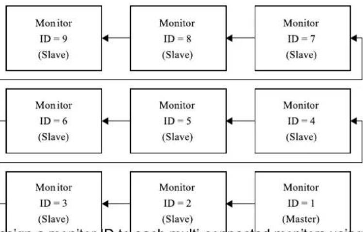
[SUPPLEMENTAL INFORMATION OF THE AUTO BRIGHTNESS FUNCTION]
To control multiple monitors collectively
In such a case where the tiling function is used, you can control the auto brightness function by sharing the detection result of the brightness sensor of a certain monitor among the connected monitors.
- Multi-connect the monitors using RS-232C cables (commercially available) as shown by the example below.
flowchart
graph TD
    A["Monitor ID = 9 (Slave)"] <--> B["Monitor ID = 8 (Slave)"]
    B <--> C["Monitor ID = 7 (Slave)"]
    D["Monitor ID = 6 (Slave)"] <--> E["Monitor ID = 5 (Slave)"]
    E <--> F["Monitor ID = 4 (Slave)"]
    G["Monitor ID = 3 (Slave)"] <--> H["Monitor ID = 2 (Slave)"]
    H <--> I["Monitor ID = 1 (Master)"]
Master: Monitor configured as Master that detects the outside light (Monitor ID is "1".)
Slave: Monitor controlled by the Master monitor (Monitor ID is other than "1".)
- Assign a monitor ID to each multi-connected monitors using MONITOR ID. (See page 38.) Monitor ID is selectable from 1 to 26. The monitor ID of the Master monitor should be "1" and those of the Slave monitors should be other than "1". You are recommended to assign IDs to the monitors consecutively from 1, 2, 3, and on.
- Set AUTO BRIGHTNESS on the OSD screen (PICTURE) as follows.
| AUTO BRIGHTNESS | CONTROL | |
| Master monitor | LOCAL | PRIMARY |
| Slave monitors | REMOTE | SECONDARY |
To use a computer to control the monitors
When using a computer to control the monitors, you must prepare an application software program for control by yourself. Brightness of all the monitors can be controlled centrally using a computer, if the customer create a control application to remotely read the value from two brightness sensors of any monitor and distribute it to all monitors.
- Connect the RS-232C IN connector of the Master monitor shown above and the RS-232C connector of the computer using an RS-232C cable. The communication control function via LAN isn't supported on the monitor alone, however, it is available when the monitor is used with the computer.
- Assign a monitor ID to each multi-connected monitors using MONITOR ID. (See page 38.) Monitor ID is selectable from 1 to 26.
- Set AUTO BRIGHTNESS on the OSD screen (PICTURE) as follows.
| AUTO BRIGHTNESS | CONTROL | |
| Master monitor | REMOTE | SECONDARY |
| Slave monitors | REMOTE | SECONDARY |
- A control application made by the customer reads the value from two brightness sensors of any monitor and distributes it to all monitors. For the specifications of the communication commands, contact your dealer.
[REMOTE CONTROL NUMBERING FUNCTION]
By connecting multiple monitors using RS-232C cables, you can control any one monitor or all the monitors by one remote controller.
- Assign arbitrary ID number to each of multi-connected monitors using MONITOR ID. ID numbers 1 to 26 are selectable. It is recommended to assign sequential ID numbers from 1 and up.
- The remote control mode of the first monitor is set to PRIMARY and those of the other monitors are set to SECONDARY.
- When you direct the remote controller at the remote control signal sensor of the PRIMARY monitor and press the DISPLAY button on the remote controller, the ID selection OSD appears at the upper left of the screen.
![IIYAMA ProLite LH5580S - [REMOTE CONTROL NUMBERING FUNCTION] - 1](/content/2026/06/1173340/images/a2a5c3f16df0ed0c4bae3e0284de0ed06d0796d9034ab637b5f2b8642177d6ab.jpg)
flowchart
graph LR
    A["ID:1"] --> B["ID No.:2"]
    B --> C["End"]
ID number of the currently viewed monitor
Select the ID number of the monitor you want to control using the +/- button on the remote controller. The ID of the monitor you want to control is displayed at the upper left of its screen. By selecting ALL, you can control all the multi-connected monitors.
- Direct the remote controller at the remote control signal sensor of the PRIMARY monitor. OSD appears on the monitor having the ID number you selected.
When the ID selection OSD is being displayed on the PRIMARY monitor, press the DISPLAY button on the remote controller again to cancel the ID selection OSD and then control the monitor you selected. If you set the remote control mode wrongly and remote control operation becomes unavailable, press any button on the control panel of the monitor to display the OSD screen and change the remote control mode using ADVANCED OPTION. By pressing and holding down the DISPLAY button on the remote control for 5 seconds or longer, the remote control mode is initialized to NORMAL.
SCREEN ADJUSTMENTS
Adjust the image by following the procedure below to get the desired picture when selecting Analog input.
■ The screen adjustments described in this manual are designed to set image position and minimize flicker or blur for the particular computer in use.
■ The monitor is designed to provide the best performance at resolution of 1920 × 1080 , but can not provide the best at resolutions of less than 1920 × 1080 because the picture is automatically stretched to fit the full screen. It is recommended to operate at resolution of 1920 × 1080 in normal use.
■ Displayed text or lines will be blurred or irregular in thickness when the picture is stretched due to the screen enlargement process.
■ It is preferable to adjust the image position and frequency with the monitor controls, rather than the computer software or utilities.
■ Perform adjustments after a warm-up period of at least thirty minutes.
■ Additional adjustments may be required after the Auto Adjust depending on the resolution or signal timing.
■ The Auto Adjust may not work correctly when displaying the picture other than the screen adjustment pattern. In this case, manual adjustments are required.
There are two ways to adjust the screen. One way is automatic adjustment for Position, Clock and Phase. The other way is performing each adjustment manually.
Perform the Auto Adjust first when the monitor is connected to a new computer, or resolution is changed. If the screen has a flicker or blur, or the picture does not fit in the display area after performing the Auto Adjust, manual adjustments are required. Both adjustments should be made by using the screen adjustment pattern (Test.bmp) obtained via the IIYAMA web site (http://www.iiyama.com).
Adjust the image by following the procedure below to get the desired picture.
This manual explains adjustment under Windows OS.
① Display the picture at the optimum resolution.
② Enter the Test.bmp (screen adjustment pattern) to wallpaper.
NOTE
■ Consult the appropriate documentation for doing this.
■ Test.bmp is made at resolution of 1280 × 1024. Set the display position to center in the wallpaper setting dialogue box. If you use Microsoft® PLUS! 95/98 cancel the setting of "Stretch desktop wallpaper to fit the screen".
[Adjustment pattern]
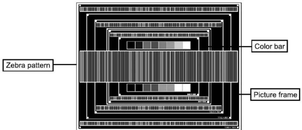
text_image
Zebra pattern Color bar Picture frame③ Adjust the Auto Adjustment.
④ Adjust the image manually by following procedure below when the screen has a flicker or blur, or the picture does not fit in the display area after performing the Auto Adjust.
⑤ Adjust the V-Position so that the top and bottom of the picture frame will fit to the display area.
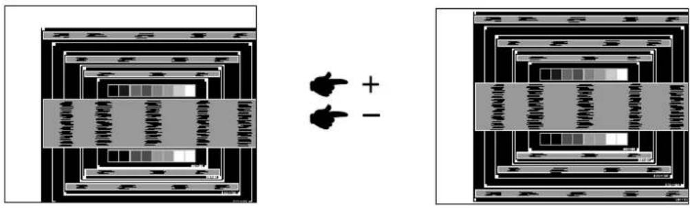
text_image
Diagram showing two layered electronic or circuitry setups with labeled components and polarity indicators⑥ 1) Adjust the H-Position so that the left side of the picture frame will move to the left edge of the display area.
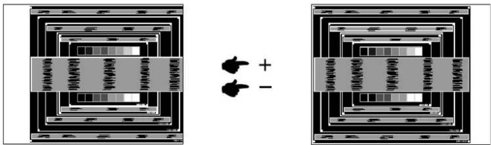
text_image
Diagram showing two identical electronic circuit layouts with labeled components and polarity indicators2) Stretch the right side of the picture frame to the right edge of the display area by adjusting the Clock.
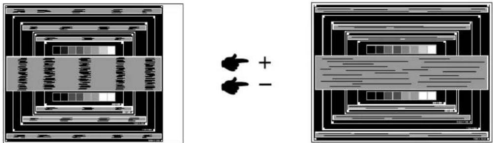
text_image
Diagram showing two panels with labeled boxes and a central symbol, possibly illustrating a process or system concept.NOTE
■ When the left side of the picture frame moves apart from the left edge of the display area during the Clock adjustment, adjust steps 1) and 2).
■ Another way to make the Clock adjustment is to correct the vertical wavy lines in the zebra pattern.
■ The picture may flicker during the Clock, H/V-Position adjustment.
In case the picture frame is bigger or smaller than the data display area after the Clock adjustment, repeat steps from ③.
⑦ Adjust the Phase to correct horizontal wavy noise, flicker or blur in the zebra pattern.
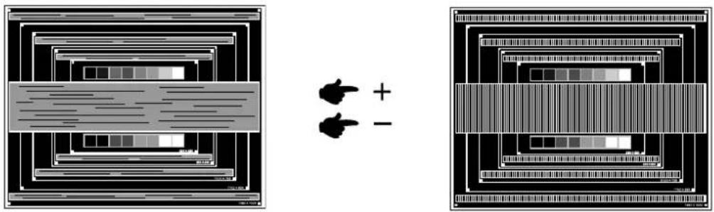
natural_image
Two abstract diagrams showing layered rectangular structures with horizontal lines and arrows, no text or symbols present.NOTE
In case the strong flicker or blurs remain on a part of the screen, repeat steps ⑥ and ⑦ because the Clock may not be adjusted correctly. If the flicker or blurs still remain, set the refresh rate of computer to low (60Hz) and repeat steps from ③ again.
■ Adjust the H-Position after the Phase adjustment if the horizontal position moves during the adjustment.
⑧ Adjust the Brightness and Color to get the desired picture after you complete the Clock and Phase adjustments.
Put back your favorite wallpaper.
POWER MANAGEMENT FEATURE
The power management feature of this product complies with power saving requirement of ENERGY STAR® and VESA DPMS. When activated, it automatically reduces unnecessary power consumption of the monitor when your computer is not in use.
To use the feature, the monitor needs to be connected to a VESA DPMS compliant computer. There is a power management step the monitor takes as described below. The power management function, including any timer settings is configured by the operating system. Check your operating system manual for information on how this can be configured.
■ Power Management Mode
When the H-sync signal / V-sync signal / H and V sync signals from the computer are off, the monitor enters into Power Management Mode which reduces the power consumption to less than 1W. The screen becomes dark. From Power Management Mode, the image reappears in several seconds when either the keyboard or the mouse are touched again.
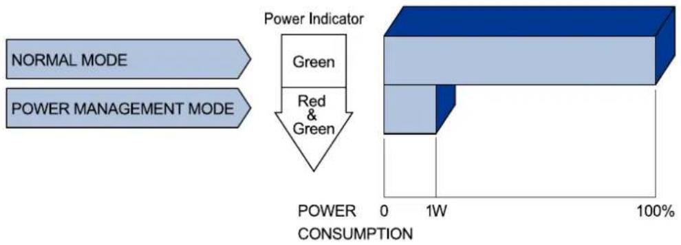
flowchart
graph TD
    A["NORMAL MODE"] --> B["Power Management Mode"]
    C["Power Indicator"] --> D["Green"]
    C --> E["Red & Green"]
    D --> F["POWER CONSUMPTION 0-1W 100%"]
    E --> F
NOTE
■ Even when using the power management mode, the monitor consumes electricity. Turn off the Power Switch whenever the monitor is not in use, during the night and weekends, to avoid unnecessary power consumption.
It is possible that the video signal from the computer may be on while the H or V sync signal is missing. In this instance, the POWER MANAGEMENT feature may not work properly.
TROUBLE SHOOTING
If the monitor fails to operate correctly, please follow the steps below for a possible solution.
- Perform the adjustments described in OPERATING THE MONITOR, depending on the problem you have. If the monitor does not get a picture, skip to 2.
- Consult the following items if you cannot find an appropriate adjustment item in OPERATING THE MONITOR or if the problem persists.
- If you are experiencing a problem which is not described below or you cannot correct the problem, discontinue using the monitor and contact your dealer or iiyama service center for further assistance.
Problem
| 1 The picture does not appear. | □The Power Cable is firmly seated in the socket. |
| □The Power Switch is turned ON. | |
| □The AC socket is live. Please check with another piece of equipment. | |
| □If the blank screen saver is in active mode, touch the keyboard or the mouse. | |
| □Increase the Contrast and/or Brightness. | |
| □The computer is ON. | |
| □The Signal Cable is properly connected. | |
| □The signal timing of the computer is within the specification of the monitor. | |
| □If the monitor is in power management mode, touch the keyboard or the mouse. | |
| 2 The screen is not synchronized. | □The Signal Cable is properly connected. |
| □The signal timing of the computer is within the specification of the monitor. | |
| □The video output level of the computer is within the specification of the monitor. | |
| 3 The screen position is not in the center. | □The signal timing of the computer is within the specification of the monitor. |
| 4 The screen is too bright or too dark. | □The video output level of the computer is within the specification of the monitor. |
| 5 The screen is shaking. | □The power voltage is within the specification of the monitor. |
| □The signal timing of the computer is within the specification of the monitor. | |
| 6 No sound. | □The audio equipment (computer etc.) is ON. |
| □The Audio Cable is properly connected. | |
| □The Volume is turned up. | |
| □The Mute is OFF. | |
| □The audio output level of the audio equipment is within the specification of the monitor. | |
| 7 The sound is too loud or too quiet. | □The audio output level of the audio equipment is within the specification of the monitor. |
| 8 A strange noise is heard. | □The Audio Cable is properly connected. |
Check
⑨ Remote control is not available
- Check the remote control's batteries status. - Check if the batteries are inserted correctly. - Check if the remote control is pointing at the monitor's remote sensor.
⑩ "SCHEDULE"/"OFF TIMER" function is not working properly
☐ The "SCHEDULE" function will be disabled when the "OFF TIMER" is set. ☐ If the "OFF TIMER" function is enabled and the power to the LCD display is turned off if the power supply is interrupted unexpectedly, then the "OFF TIMER" will be reset.
RECYCLING INFORMATION
For better environment protection please don't dispose your monitor. Please visit our web site: www.iiyama.com/recycle for monitor recycling.
APPENDIX
Design and specifications are subject to change without prior notice.
SPECIFICATIONS
| Size Category | 55" | |
| LCD Panel | Panel technology | VA |
| Size | Diagonal: 54.6" (138.8cm) | |
| Pixel pitch | 0.630mm H × 0.630mm V | |
| Brightness | 450cd/m2(Typical) | |
| Contrast ratio | 4000 : 1 (Typical) | |
| Viewable angle | Horizontal : 178 degrees, Vertical: 178 degrees (Typical) | |
| Response time | 6.5ms (Gray to Gray) | |
| Display Colors | Approx.1.06B | |
| Sync Frequency | Analog: Horizontal: 15.625/15.734, 31.5-91.1kHz, Vertical: 50/58-85HzDigital: Horizontal: 31.5-91.1kHz, Vertical: 50/58-85Hz | |
| Maximum Resolution | 1920 × 1080, 2.1 MegaPixels | |
| Input Connector | D-Sub mini 15 pin, DVI-D 24 pin, HDMIx2, DisplayPort | |
| Input Video Connector | BNC jack, S-Video | |
| Input Audio Connector | mini jack | |
| LAN | RJ45 | |
| Serial Port | RS-232C In/Out | |
| Plug & Play | VESA DDC2BTM | |
| Input Sync Signal | Separate sync: TTL, Positive or Negative | |
| Input Video Signal | Analog: 0.7Vp-p (Standard), 75Ω, PositiveDigital: DVI (Digital Visual Interface Standard Rev.1.0) complianceDigital: HDMI, DisplayPort | |
| Input Audio Signal | 2.0Vrms maximum | |
| Output Connector | DVI-D 24 pin | |
| Output Video Connector | BNC jack | |
| Output Audio Connector | mini jack | |
| USB Standard | USB2.0 | |
| Number of USB Ports Connector shape | 1 Upstream : Series B2 Downstream : Series A | |
| Speakers | Internal: 10W×2 (Stereo speakers), External speaker jack: 10W×2 | |
| Maximum Screen Size | 1209.6mm W × 680.4mm H / 47.6" W × 26.8" H | |
| Power Source | 100-240V~, 50 - 60Hz, 1.8A - 0.8A | |
| Power Consumption* | 133W typical, Power management mode: 1W maximum | |
| Dimensions / Net Weight | 1247.0 × 718.0 × 66.5mm / 49.1 × 28.3 × 2.6" (W×H×D)28.5kg / 62.8lbs | |
| Environmental Considerations | Operating: Temperature 0 to 35°C / 32 to 95°FHumidity 20 to 80% (No condensation)Storage: Temperature -20 to 60°C / 4 to 140°FHumidity 10 to 90% (No condensation) | |
| Approvals | CB, CE, EAC, TÜV-Bauart, ENERGY STAR® | |
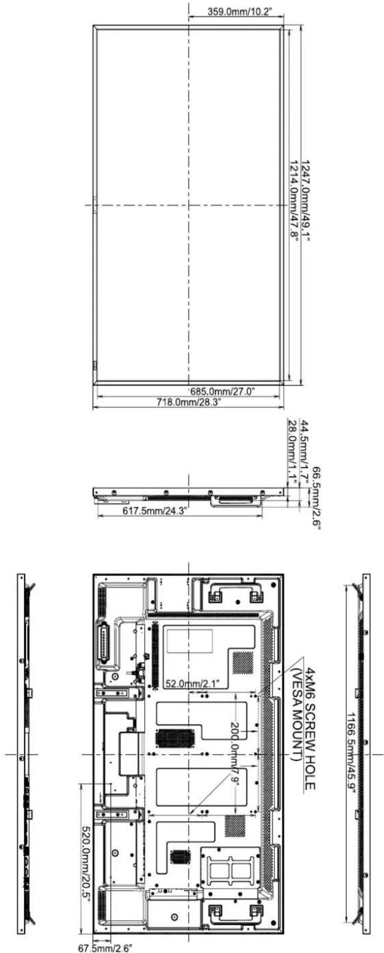
| Timing | fH(kHz) | fV(Hz) | Dot clock (MHz) | VGA | DVI | DisplayPort | HDMI | YPbPr | AV | S-Video | ||
| VESA | VGA 640x480 | 31.470 | 59.940 | 25.180 | ○ | ○ | ○ | ○ | ||||
| SVGA 800x600 | 37.880 | 60.320 | 40.000 | ○ | ○ | ○ | ○ | |||||
| XGA 1024x768 | 48.360 | 60.000 | 65.000 | ○ | ○ | ○ | ○ | |||||
| 1280x720 | 45.000 | 60.000 | 74.250 | ○ | ○ | ○ | ○ | |||||
| 1280x768 | 47.780 | 59.870 | 79.500 | ○ | ○ | ○ | ○ | |||||
| WXGA 1280x800 | 49.702 | 59.810 | 83.500 | ○ | ○ | ○ | ○ | |||||
| SXGA 1280x1024 | 63.980 | 60.020 | 108.000 | ○ | ○ | ○ | ○ | |||||
| 1366x768 | 47.700 | 60.000 | 85.380 | ○ | ○ | ○ | ○ | |||||
| 1400x1050 | 65.320 | 59.980 | 121.750 | ○ | ○ | ○ | ○ | |||||
| 1440x900 | 55.935 | 59.887 | 106.500 | ○ | ○ | ○ | ○ | |||||
| 1680x1050 | 64.674 | 59.883 | 119.000 | ○ | ○ | ○ | ○ | |||||
| 1920x1080(Recommend) | 67.158 | 59.963 | 148.500 | ○ | ○ | ○ | ○ | |||||
| IBM | 720x400 | 31.470 | 70.080 | 28.320 | ○ | ○ | ○ | ○ | ||||
| MAC | 1920x1080 | 67.625 | 60.110 | 160.000 | ○ | ○ | ○ | ○ | ||||
| SD | NTSC | 15.734 | 59.940 | 13.500 | ○ | ○ | ○ | |||||
| 4.43NTSC | 15.734 | 59.940 | 13.500 | ○ | ○ | ○ | ||||||
| PAL | 15.625 | 50.000 | 13.500 | ○ | ○ | ○ | ||||||
| PAL-60 | 15.734 | 59.940 | 13.500 | ○ | ○ | ○ | ||||||
| SECAM | 15.625 | 50.000 | 13.500 | ○ | ○ | ○ | ||||||
| 480i | 60Hz | 15.734 | 59.940 | 13.500 | ○ | ○ | ||||||
| 576i | 50Hz | 15.625 | 50.000 | 13.500 | ○ | ○ | ||||||
| 480p | 60Hz | 31.469 | 59.940 | 27.000 | ○ | ○ | ○ | ○ | ||||
| 576p | 50Hz | 31.250 | 50.000 | 27.000 | ○ | ○ | ○ | ○ | ||||
| HD | 720p | 50Hz | 37.500 | 50.000 | 74.250 | ○ | ○ | ○ | ○ | |||
| 60Hz | 44.955 | 59.940 | 74.250 | ○ | ○ | ○ | ○ | |||||
| 1080i | 50Hz | 28.125 | 50.000 | 74.250 | ○ | ○ | ○ | ○ | ||||
| 60Hz | 33.716 | 59.940 | 74.250 | ○ | ○ | ○ | ○ | |||||
| 1080p | 50Hz | 56.250 | 50.000 | 148.500 | ○ | ○ | ○ | ○ | ||||
| 60Hz | 67.432 | 59.940 | 148.500 | ○ | ○ | ○ | ○ | |||||
* ○ means supported the timing.
PIP SUPPORT SCREEN TABLE
The following table shows the combinations of signal inputs with which the "PIP" and "POP" modes function. However, these modes do not function when the screen size is "CUSTOM" or "REAL".
| SubMain | HDMI1 | HDMI2 | DVI-D | D-SUB | YPbPr | VIDEO | ||
| HDMI1 | — | — | — | — | — | — | ○ | ○ |
| HDMI2 | — | — | — | — | — | — | ○ | ○ |
| DVI-D | — | — | — | — | — | — | ○ | ○ |
| D-SUB | — | — | — | — | — | — | ○ | ○ |