
INNOV-IS 700E - Machine à coudre à broder BROTHER - Notice d'utilisation et mode d'emploi gratuit
Retrouvez gratuitement la notice de l'appareil INNOV-IS 700E BROTHER au format PDF.

| Type de produit | Machine à coudre brodeuse électronique |
| Caractéristiques techniques principales | Broderie avec 138 motifs intégrés, 11 polices de caractères, écran LCD couleur, zone de broderie de 10 x 10 cm |
| Alimentation électrique | Adaptateur secteur 100-240V |
| Dimensions approximatives | Env. 50 x 25 x 40 cm |
| Poids | Env. 8 kg |
| Compatibilités | Compatible avec les fichiers de broderie au format PES, DST, JEF, XXX |
| Fonctions principales | Broderie automatique, personnalisation des motifs, fonction de mise en mémoire des motifs |
| Entretien et nettoyage | Nettoyage régulier du boîtier et de la zone de broderie, lubrification des pièces mobiles |
| Pièces détachées et réparabilité | Disponibilité de pièces détachées via le service après-vente Brother |
| Sécurité | Protection contre les surcharges, arrêt automatique après une période d'inactivité |
| Informations générales utiles | Garantie de 3 ans, support technique disponible, manuel d'utilisation inclus |
FOIRE AUX QUESTIONS - INNOV-IS 700E BROTHER
Questions des utilisateurs sur INNOV-IS 700E BROTHER
0 question sur cet appareil. Repondez a celles que vous connaissez ou posez la votre.
Poser une nouvelle question sur cet appareil
Téléchargez la notice de votre Machine à coudre à broder au format PDF gratuitement ! Retrouvez votre notice INNOV-IS 700E - BROTHER et reprennez votre appareil électronique en main. Sur cette page sont publiés tous les documents nécessaires à l'utilisation de votre appareil INNOV-IS 700E de la marque BROTHER.
MODE D'EMPLOI INNOV-IS 700E BROTHER
1 GETTING READY
2 EMBROIDERY
3 APPENDIX
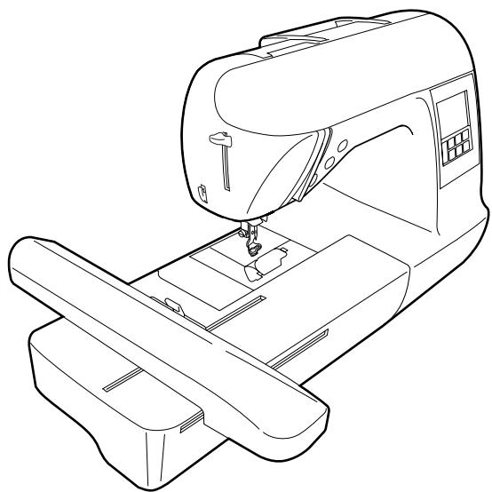
natural_image
Line drawing of a sewing machine with no visible text or symbolsComputerized Embroidery Machine
Operation Manual
IMPORTANT SAFETY INSTRUCTIONS
Please read these safety instructions before attempting to use the machine.
DANGER - To reduce the risk of electric shock
1 Always unplug the machine from the electrical outlet immediately after using, when cleaning, when making any user servicing adjustments mentioned in this manual, or if you are leaving the machine unattended.
WARNING - To reduce the risk of burns, fire, electric shock, or injury to persons.
2 Always unplug the machine from the electrical outlet when removing covers, lubricating, or when making any adjustments mentioned in the instruction manual.
- To unplug the machine, switch the machine to the symbol "O" position to turn it off, then grasp the plug and pull it out of the electrical outlet. Do not pull on the cord.
- Plug the machine directly into the electrical outlet. Do not use an extension cord.
• Always unplug your machine if the power is cut.
3 Never operate this machine if it has a damaged cord or plug, if it is not working properly, if it has been dropped or damaged, or water is spilled on the unit. Return the machine to the nearest authorized dealer or service center for examination, repair, electrical or mechanical adjustment.
4 Always keep your work area clear:
- Never operate the machine with any air openings blocked. Keep ventilation openings of the machine free from the build up of lint, dust, and loose cloth.
- Do not use extension cords. Plug the machine directly into the electrical outlet.
- Never drop or insert any object into any opening.
- Do not operate where aerosol (spray) products are being used or where oxygen is being administered.
5 Special care is required when embroidering:
- Always pay close attention to the needle. Do not use bent or damaged needles.
- Keep fingers away from all moving parts. Special care is required around the machine needle.
- Switch the machine to the symbol “O” position to turn it off when making any adjustments in the needle area.
- Do not use a damaged or incorrect needle plate, as it could cause the needle to break.
- Do not push or pull the fabric when embroidering.
6 This machine is not a toy:
- Your close attention is necessary when the machine is used by or near children.
- Do not use outdoors.
7 For a longer service life:
- When storing this machine, avoid direct sunlight and high humidity locations. Do not use or store the machine near a space heater, iron, halogen lamp, or other hot objects.
- Use only neutral soaps or detergents to clean the case. Benzene, thinner, and scouring powders can damage the case and machine, and should never be used.
- Always consult the operation manual when replacing or installing any assemblies, the presser feet, needle, or other parts to assure correct installation.
8 For repair or adjustment:
- If the Light unit is damaged, it must be replaced by authorized dealer.
- In the event a malfunction occurs or adjustment is required, first follow the troubleshooting table in the back of the operation manual to inspect and adjust the machine yourself. If the problem persists, please consult your local authorized Brother dealer.
Use this machine only for its intended use as described in the manual.
Use accessories recommended by the manufacturer as contained in this manual.
The contents of this manual and specifications of this product are subject to change without notice.
For additional product information and updates, visit our web site at www.brother.com
SAVE THESE INSTRUCTIONS This machine is intended for household use.
FOR USERS IN THE UK, EIRE, MALTA AND CYPRUS ONLY
IMPORTANT
- In the event of replacing the plug fuse, use a fuse approved by ASTA to BS 1362, i.e. carrying the mark, rating as marked on plug.
• Always replace the fuse cover. Never use plugs with the fuse cover omitted. - If the available electrical outlet is not suitable for the plug supplied with this equipment, you should contact your authorized dealer to obtain the correct lead.
FOR USERS IN AC INPUT 220-240V COUNTRIES AND MEXICO
This appliance is not intended for use by persons (including children) with reduced physical, sensory or mental capabilities, or lack of experience and knowledge, unless they have been given supervision or instruction concerning use of the appliance by a person responsible for their safety.
Children should be supervised to ensure that they do not play with the appliance.
Contents
Introduction .... 5
Machine Features ....5
Accessories......6
Included accessories 6
Optional accessories....7
Names of Machine Parts and Their Functions 8
Front view....8
Needle and embroidery foot section 9
Right-side/rear view 9
Operation buttons 10
Operation panel....11
GETTING READY
13
Embroidery Step by Step 14
Attaching the Embroidery Unit....15
Embroidery unit precautions 15
Attaching the embroidery unit....15
Removing the embroidery unit 16
Turning the Machine On/Off....18
Power supply precautions 18
Turning on the machine 19
Turning off the machine 19
LCD (Liquid Crystal Display) Operation....20
Viewing the LCD 20
Changing the machine settings....21
Checking machine operating procedures 23
Winding/Installing the Bobbin....24
Bobbin precautions 24
Winding the bobbin 24
Installing the bobbin 28
Upper Threading 30
About the spool of thread....30
Threading the upper thread 30
Threading the needle 32
Threading the needle manually (without using the needle threader) 34
Replacing the Needle 35
Needle precautions 35
Checking the needle 35
Replacing the needle....36
EMBROIDERY
39
Embroidering Neatly 40
What to prepare 40
Preparing the Fabric 42
Attaching a stabilizer material to the fabric 42
Setting the fabric in the embroidery frame 43
Attaching the Embroidery Frame 47
Attaching the embroidery frame 47
Removing the embroidery frame 48
Selecting Embroidery Patterns....49
Copyright information 49
Embroidery pattern types....49
LCD (liquid crystal display) operation 50
Selecting characters 52
Selecting an embroidery pattern....53
Selecting a frame pattern....54
Using an embroidery card (sold separately) 55
Embroidering....56
Embroidering attractive finishes....56
Embroidering a pattern....57
Appliquéing 59
Editing and Saving Patterns ....61
Adjusting the layout 61
Storing patterns 63
Adjusting the thread tension....64
Resewing 65
Thread runs out partway through a design....65
Stopping while embroidering 66
Bobbin Case Adjustment 68
Correct tension....68
Bobbin thread is loose....68
Bobbin thread is tight....68
APPENDIX 69
Care and Maintenance ....70
Cleaning the machine surface 70
Cleaning the race....70
Attaching the Embroidery Foot....72
Attaching the embroidery Foot "Q" 72
Troubleshooting 74
Error messages 78
Adjusting the LCD 81
Operation beep....81
Canceling the operation beep 82
Index 83
Introduction
Thank you for purchasing this embroidery machine. Before using the machine, carefully read the "IMPORTANT SAFETY INSTRUCTIONS", and then study this manual for the correct operation of the various functions. In addition, after you have finished reading this manual, store it where it can quickly be accessed for future reference.
Machine Features
① Simple bobbin-winding
The bobbin can quickly and easily be wound with thread (page 24).
② Quick-set bobbin
You can start embroiderying without pulling up the bobbin thread (page 28).
③ Automatic thread cutting
The thread can be cut automatically after embroidering (page 51).
④ Embroidery
You can embroider built-in embroidery patterns, characters, framed decorations, and designs from optional embroidery cards (page 39).
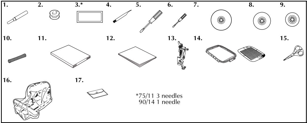
Accessories
Included accessories
After opening the box, check that the following accessories are included. If any item is missing or damaged, contact your retailer.
| No. | Part Name | Part Code | No. | Part Name | Part Code | ||
| U.S.A. / Canada | Others | U.S.A. / Canada | Others | ||||
| 1 | Seam ripper | X54243-051 | 10 | Spool net | XA5523-020 | ||
| 2 | Bobbin (4) | SA156 | SFB:XA5539-151 | 11 | Operation manual | XD1628-121 | |
| 12 | Quick reference guide | XD1629-021 | |||||
| 13 | Embroidery foot “Q”(on machine) | XD0474-151 | |||||
| 3 | Needle set | X59535-051 | |||||
| 4 | Cleaning brush | X59476-021 | 14 | Embroidery set (large)H 18cm X W 13 cm(H 7 inches X W 5 inches) | SA444/EF84 | EF84:XD0600-002 | |
| 5 | Screwdriver (large) | XC8349-021 | |||||
| 6 | Screwdriver (small) | X55468-051 | |||||
| 7 | Spool cap (large) | 130012-024 | 15 | Scissors | XC1807-121 | ||
| 8 | Spool cap (medium) | XE1372-001 | 16 | Dust cover | XZ5004-021 | ||
| 9 | Spool cap (small) | 130013-124 | 17 | Accessory bag | XC4487-021 | ||
Optional accessories
The following are available as optional accessories.
1.
2.
3.
4.

5.
6.
| No. | Part Name | Part Code | No. | Part Name | Part Code | ||
| U.S.A. / Canada | Other | U.S.A. / Canada | Other | ||||
| 1 | Brother poly #90 bobbin thread | EBT-PE | EBT-PEN: XC5996-001 | 5 | Embroidery set (medium) H 10 cm X W 10 cm (H 4 inches X W 4 inches) | SA443/ EF83 | EF83: XD0599-002 |
| 2 | Water solude stabilizer | SA520 | BM4: X81267-001 EBT-CEN | ||||
| Stabilizer material for embroidery | SA519 | BM3: X81175-001 EBT-CEN | 6 | Embroidery set (extra large (multi-position)) H 30 cm X W 13 cm (H 12 inches X W 5 inches) | SA445 | EF85: XD0601-002 | |
| 3 | Embroidery card | — | |||||
| 4 | Embroidery set (small) H 2 cm X W 6 cm (H 1 inch X W 2-1/2 inches) | SA442/ EF82 | EF82: XD0598-002 | ||||

Memo
● To obtain optional accessories or parts, contact your sales representative or the nearest authorized service center.
● All specifications are correct at the time of printing. The part codes are subject to change without notice.
- Visit your nearest authorized retailer for a complete listing of optional accessories available for your machine.
Names of Machine Parts and Their Functions
The names of the various parts of the machine and their functions are described below. Before using the machine, carefully read these descriptions to learn the names of the machine parts.
Front view
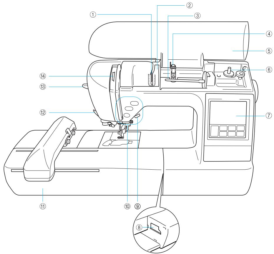
① Thread guide plate
Pass the thread around the thread guide plate when threading the upper thread.
② Thread guide cover
Like with the thread guide plate, pass the thread around the thread guide cover when threading the upper thread.
③ Spool pin
Place a spool of thread on the spool pin.
④ Bobbin winding thread guide
Pass the thread around this thread guide when winding the bobbin thread.
⑤ Top cover
Open the top cover to place the spool of thread on the spool pin.
⑥ Bobbin winder
Use the bobbin winder when winding the bobbin.
⑦ Operation panel
From the operation panel, patterns can be selected and edited, and operations for using the machine can be displayed (page 11).
⑧ Embroidery unit connector slot
Plug in the connector for the embroidery unit.
⑨ Presser foot lever
Raise and lower the presser foot lever to raise and lower the presser foot
⑩ Operation buttons
Use these buttons to operate the machine.
⑪ Embroidery unit
Attach the embroidery unit to the machine, and then attach the embroidery frame.
⑫ Thread cutter
Pass the threads through the thread cutter to cut them.
⑬ Needle threader lever
Use the needle threader lever to thread the needle.
⑭ Thread take-up lever check window
Look through the window to check the position of the take-up lever.
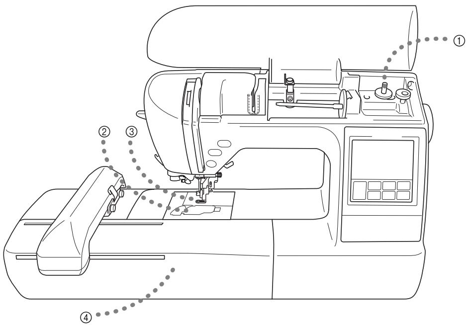
Needle and embroidery foot section
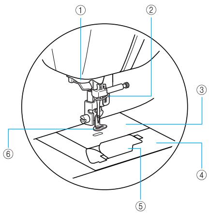
① Thread guide disk
Pass the thread through the thread guide disk when using the needle threader to thread the needle.
② Needle bar thread guide
Pass the upper thread through the needle bar thread guide.
③ Needle plate
When the needle is lowered, it enters the hole in the needle plate.
④ Needle plate cover
Remove the needle plate cover to clean the bobbin case and race.
⑤ Bobbin cover/bobbin case
Remove the bobbin cover, and then insert the bobbin into the bobbin case.
⑥ Embroidery foot "Q"
This presser foot is used for embroidering.
Right-side/rear view
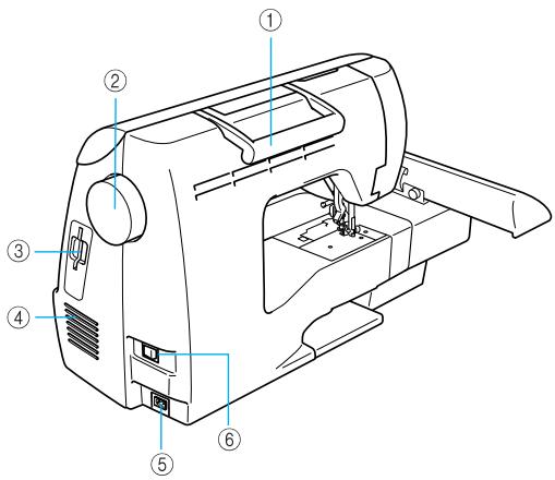
① Handle
Carry the machine by its handle when transporting the machine.
② Handwheel
Turn the handwheel toward you (counterclockwise) to raise and lower the needle.
③ Embroidery card slot
Insert the embroidery card.
④ Air vent
The air vent allows the air surrounding the motor to be exchanged. Do not cover the air vent while the machine is being used.
⑤ Power supply jack
Insert the plug on the power supply cord into the power supply jack.
⑥ Main power switch
Use the main power switch to turn the machine on and off.

Memo
- Refer to pages 8 through 11 while you are learning to use your machine.
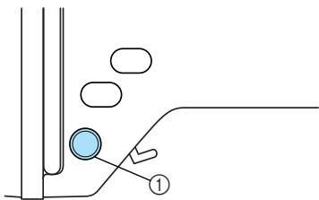
Operation buttons
The operation buttons help you to easily perform various basic machine operations.
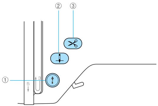
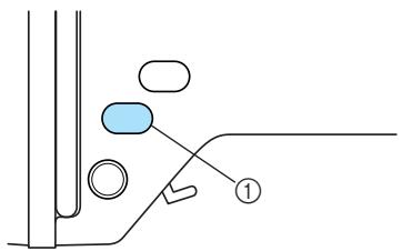
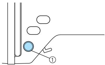
① Start/stop button
Press the start/stop button to start or stop embroidering. The machine embroiders at a slow speed while the button is pressed. When embroidering is stopped, the needle is lowered in the fabric.
The button changes color according to the machine's operation mode.
Green: The machine is ready to embroider or is embroidering.
Red: The machine can not embroider.
Orange: The machine is winding the bobbin thread, or the bobbin winder shaft is moved to the right side.
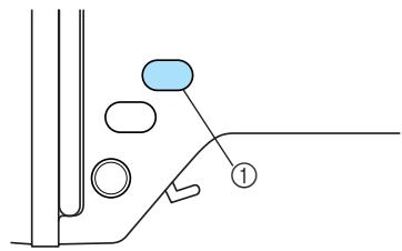
② Needle position button
Press the needle position button to raise or lower the needle. Pressing the button twice sews one stitch.
③ Thread cutter button ✗
Press the thread cutter button after embroidering is stopped to cut both the upper and the bobbin threads.

CAUTION
- Do not press the thread cutter button after the threads have already been cut, otherwise the needle may break, the threads may become tangled or damage to the machine may occur.
Note
- Do not press the thread cutter button if there is no fabric under the presser foot or while the machine is embroidering, otherwise damage to the machine may occur.
- When cutting thread thicker than #30, nylon thread or other special threads, use the thread cutter on the side of the machine.
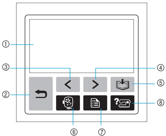
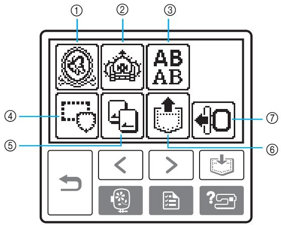
Operation panel
The front operation panel has an LCD (liquid crystal display) and operation keys.
flowchart
graph TD
    A["①"] --> B["←"]
    C["③"] --> B
    D["②"] --> B
    E["④"] --> F["<<"]
    G["⑤"] --> H[">"]
    I["⑥"] --> J["?"]
    K["⑦"] --> J
    L["⑧"] --> J
① LCD (liquid crystal display) (touch panel)
Touch the keys displayed on the LCD to perform operations.
For details, refer to "LCD (Liquid Crystal Display) Operation" (page 20).
② Back key
Press to return to the previous screen.
③ Previous page key
Press to display the previous screen when there are items that are not displayed on the LCD.
④ Next page key ▶
Press to display the next screen when there are items that are not displayed on the LCD.
⑤ Memory key
Press to store patterns in the machine's memory.
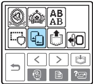
⑥ Embroidery key
Press to display the pattern type selection screen.
⑦ Settings key
Press to display the settings screen.
⑧ Help key ?
Press to get help on using the machine.
Displays simple explanations of setting upper thread / bobbin winding / setting bobbin thread / embroidery unit attachment / embroidery frame attachment / needle replacement.
1
GETTING READY
The various preparations to start embroidering are described in this chapter.
Embroidery Step by Step ...... 14
Attaching the Embroidery Unit....15
Embroidery unit precautions....15
Attaching the embroidery unit ....15
Removing the embroidery unit....16
Turning the Machine On/Off ....18
Power supply precautions 18
Turning on the machine 19
Turning off the machine....19
LCD (Liquid Crystal Display) Operation....20
Viewing the LCD 20
Changing the machine settings....21
Checking machine operating procedures 23
Winding/Installing the Bobbin....24
Bobbin precautions 24
Winding the bobbin 24
Installing the bobbin ......28
Upper Threading....30
About the spool of thread ....30
Threading the upper thread....30
Threading the needle....32
Threading the needle manually (without using the needle threader)....34
Replacing the Needle 35
Needle precautions 35
Checking the needle....35
Replacing the needle....36
Embroidery Step by Step
The basic steps for embroidery are as follows.
| 1 | Attaching the embroidery unit | Attach the embroidery unit. (If the embroidery unit is not attached, the machine does not operate.)For details, refer to “Attaching the embroidery unit” (page 15). |
| 2 | Checking the needle | Use a needle matched to the fabric.For details on replacing the needle, refer to “Replacing the needle” (page 36). |
| 3 | Setting up the bobbin thread | For the bobbin thread, wind embroidery bobbin thread and set it in place.For details, refer to “Winding/Installing the Bobbin” (page 24). |
| 4 | Preparing the fabric | Attach a stabilizer material to the fabric, and hoop it in an embroidery frame.For details, refer to “Preparing the Fabric” (page 42). |
| 5 | Attaching the embroidery frame | Attach the embroidery frame to the embroidery unit.For details, refer to “Attaching the Embroidery Frame” (page 47). |
| 6 | Selecting a pattern | Select an embroidery pattern.For details, refer to “Selecting Embroidery Patterns” (page 49). |
| 7 | Checking the layout | Check and adjust the size and position of the embroidery pattern.For details on adjusting the layout, refer to “Adjusting the layout” (page 61). |
| 8 | Setting up the embroidery thread | Set up the embroidery thread according to the pattern.For details, refer to “Upper Threading” (page 30). |
Attaching the Embroidery Unit
This section describes how to attach the embroidery unit. Before turning on the machine, attach the embroidery unit to it. If the embroidery unit is not attached, the machine does not operate.
Embroidery unit precautions
Cautions for the embroidery unit will be explained below.

CAUTION
- Do not move the machine with the embroidery unit in place. The embroidery unit may be dropped and cause injury.
- Keep your hands and other objects away from the embroidery carriage and frame. Otherwise injury may result.

Note
- Do not touch the connector in the embroidery unit connector slot. The connector could be damaged, and it may cause malfunctions.
- Do not lift up on the embroidery carriage, and do not forcefully move it. It may cause malfunctions.
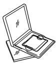
Attaching the embroidery unit
Get the included embroidery unit ready.
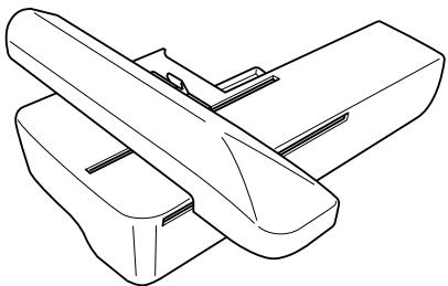
natural_image
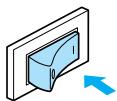
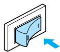
Line drawing of two mechanical components with no text or symbols1 Turn off the machine.
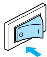
2 Slide the embroidery unit onto the machine arm.
Push it in until it clicks and stops.
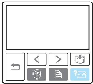
natural_image
Illustration of a sewing machine needle stitching a blue plastic box (no text or symbols)The embroidery unit is attached.
3 Turn on the machine.
- For details, refer to “Turning on the machine” (page 19).

The confirmation message is displayed.
4 Be sure that no objects or hands are near the embroidery unit and press OK.

The carriage of the embroidery unit will move.
OK
- When an animation is displayed on the screen, the message above will be displayed if you touch the screen with your finger.
The carriage moves to its initial position.
natural_image
Line drawing of a sewing machine needle stitching a blue fabric component (no text or symbols)① Carriage

CAUTION
- Do not put your hands or other objects near the carriage. It may cause injury.

Note
- If the machine is initialized with hands or objects near the carriage, the screen may return to the initial display. After removing whatever is near the carriage, turn the power on again.
The screen for selecting the embroidery pattern type is displayed.
- For details on the embroidery patterns, refer to "Selecting Embroidery Patterns" (page 49).
Removing the embroidery unit
Make sure that the machine is completely stopped and follow the instructions below.
1 Remove the embroidery frame.
- For details on removing the embroidery frame, refer to “Removing the embroidery frame” (page 48).
2 Press 🔍, and then press OK.
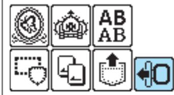
The embroidery carriage moves into a position where it can be stored.
3 Turn off the machine.
- For details, refer to "Turning off the machine" (page 19).
CAUTION
● Always turn off the machine before removing the embroidery unit. It may cause malfunctions if removed when the machine is turned on.
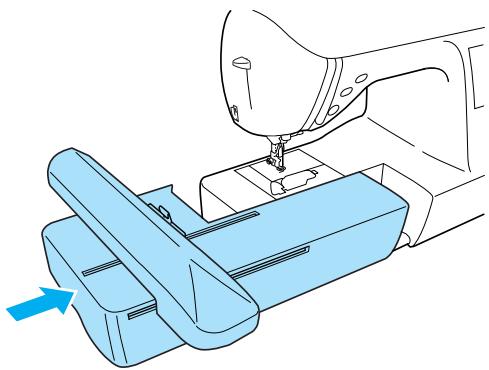
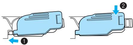
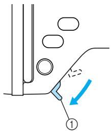
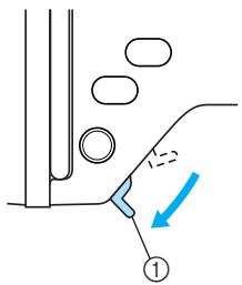
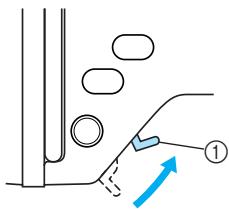
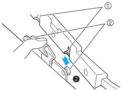
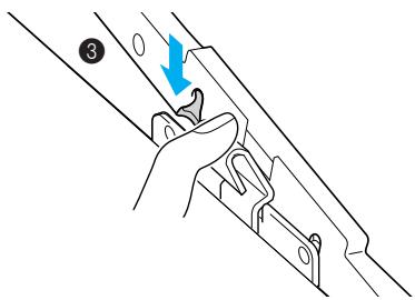
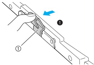
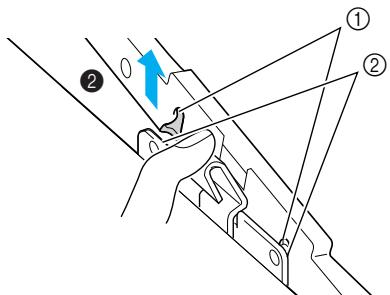
4 Hold the release button on the bottom left of the embroidery unit, and slowly pull the embroidery unit to the left.
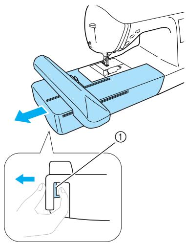
natural_image
Illustration of a sewing machine needle being adjusted, showing the mechanism and component (no text or symbols present)① Release button
The embroidery unit separates from the machine.
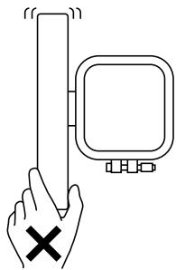
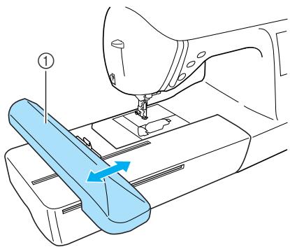
CAUTION
- Do not carry the embroidery unit by holding the release button compartment.
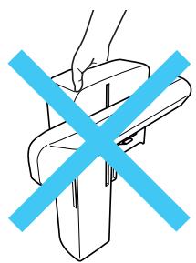
natural_image
Simple line drawing of a hand holding a rectangular object with a blue X symbol crossed out (no text or symbols present)Turning the Machine On/Off
This section explains how to turn the machine on and off.
Power supply precautions
Be sure to observe the following precautions concerning the power supply.

WARNING
- Use only regular household electricity for the power source. Using other power sources may result in fire, electric shock, or damage to the machine.
● Turn off the main power and remove the plug in the following circumstances: - When you are away from the machine
• After using the machine - When the power fails during use
- When the machine does not operate correctly due to a bad connection or a disconnection
• During electrical storms

CAUTION
- Do not use extension cords or multi-plug adapters with many other appliances plugged in to them. Fire or electric shock may result.
- Do not touch the plug with wet hands. Electric shock may result.
- When unplugging the machine, always turn off the main power first. Always grasp the plug to remove it from the outlet. Pulling on the cord may damage the cord, or lead to fire or electric shock.
- Do not allow the power cord to be cut, damaged, modified, forcefully bent, pulled, twisted, or bundled. Do not place heavy objects on the cord. Do not subject the cord to heat. These things may damage the cord and cause fire or electric shock. If the cord or plug is damaged, take the machine to your authorized dealer for repairs before continuing use.
● Unplug the power cord if the machine is not to be used for a long period of time. Otherwise a fire may result.
Turning on the machine
Before turning on the machine, be sure to attach the embroidery unit to it. If the embroidery unit is not attached, the machine does not operate. (For details, refer to “Attaching the Embroidery Unit” (page 15).)
Prepare the included power cord.
1 Make sure that the machine is turned off (the main power switch is set to “○”), and then plug the power supply cord into the power supply jack on the right side of the machine.
2 Insert the plug of the power supply cord into a household electrical outlet.
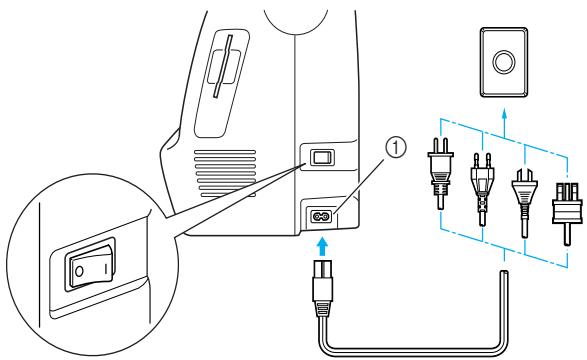
① Power supply jack
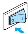
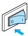
3 Press the right side of the main power switch on the right side of the machine to turn the machine on (set it to “|”).
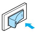
The lamps, LCD and ⏻ (Start/stop button) light up when the machine is turned on.
Turning off the machine
When you are finished using the machine, turn it off. In addition, before transporting the machine to another location, be sure to turn it off.
1 Make sure that the machine is completely stopped.
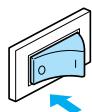
2 Press the left side of the main power switch on the right side of the machine to turn the machine off (set it to “○”).
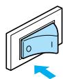
The lamps go off when the machine is turned off.
3 Unplug the power supply cord from the electrical outlet.
Grasp the plug when unplugging the power supply cord.
4 Unplug the power supply cord from the power supply jack.

Note
- If a power outage occurs while the machine is being operated, turn off the machine and unplug the power supply cord. When restarting the machine, follow the necessary procedure to correctly operate the machine.
(For U.S.A. only)
- This appliance has a polarized plug (one blade wider than the other). To reduce the risk of electrical shock, this plug is intended to fit in a polarized outlet only one way. If the plug does not fit fully in the outlet, reverse the plug. If it still does not fit, contact a qualified electrician to install the proper outlet. Do not modify the plug in any way.
LCD (Liquid Crystal Display) Operation
From the LCD, patterns can be selected and edited, and operations for using the machine can be displayed (page 11).
Viewing the LCD
When the machine is turned on, the opening screen appears. The screen shown below appears after the confirmation message was displayed by lightly touching the LCD. (The machine can be set so that the opening screen is not displayed (page 21).)
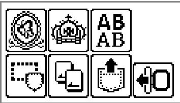
■ Pattern type selection screen
① Embroidery patterns
② Additional embroidery patterns
③ Alphabet patterns
④ Frame patterns
⑤ Embroidery card
⑥ Patterns stored in the machine's memory
⑦ Moves the embroidery unit carriage to its storage position

Memo
- Refer to "Error messages" (page 78) for messages displayed on the LCD.
● Depending on the model, a different screen may be displayed when the machine is turned on.
Changing the machine settings
Various machine operations and embroidery settings can be changed.
The attributes that can be set are listed below.
| Attribute | Icon | Details | Settings |
| Thread color display |  | Changes the thread color display on the embroidery screen. | Thread color/Time to embroider/ Needle count/Thread number (#123) |
| (When “Thread No. #123” is selected) | Embroidery/Country/Madeira poly/ Madeira rayon/Sulky/Robison anton | ||
| Display unit |  | Selects the measurement units that are displayed (only for embroidering). | mm/INCH |
| Embroidery tension |  | Adjusts the thread tension for embroidering (only for embroidering). | -8 to +8 |
| Max embroidery speed |  | Specifies the maximum embroidering speed. | |
| Buzzer |  | Specifies whether or not a beep is sounded with each operation (page 82). | |
| Opening screen |  | Sets whether or not to display the opening screen when the power is turned on. (There are models where this cannot be changed.) | |
| Language |  | Allows the language used in the screens to be changed. | English/German/French/Italian/ Dutch/Spanish/Japanese/Danish/ Norwegian/Finnish/Swedish/ Portuguese/Russian/Korean/Thai/ others |
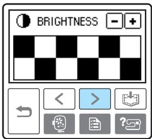
| LCD brightness | Adjusts the brightness of the LCD. | Lighter Darker | |
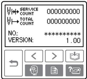
| Stitch counter | Display the service count and the total number of embroidery stitches. The service count is a reminder to take your machine in for regular servicing. (Contact your authorized dealer for details.) | - | |
| Product number | NO.: | The “NO.” is the number for the machine. | - |
| Program version | VERSION: | Display the program version. | - |

Note
● The items shown in reverse highlighting are the settings at the time of purchase.
- For details on the embroidering settings, refer to “LCD (liquid crystal display) operation” (page 50).
1 Turn on the machine.
The LCD comes on.
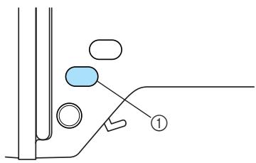
2 Press (Settings key) on the operation panel.
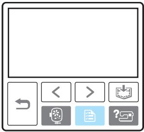
The settings screen appears.
Press the item to be set.
Switch screens using < (Previous page key) and > (Next page key).
![[NAME OF COLOR] [ ---- ]](/content/2025/01/74636/images/dc2cc75593e2b9d54148b3c1987db28fd8f6d30af1baa7295eff297ed9491e9d.jpg)
![[ mm ] EMBROIDERY TENSION MAX EMBROIDERY SPEED 650 350 SPM 5PM](/content/2025/01/74636/images/8d35c5d8f13ad69b9814f2ae6d0e83a3f4a9b3d63e62a799fb7c5c2f0aa1d2ef.jpg)
![BUZZER ON OFF OPENING ON OFF [ ENGLISH ]](/content/2025/01/74636/images/a49eee3fb20924d2bccff36092a4ea8cc34336360c934e792ca2889e3d3156de.jpg)
☐ Example: Changing the maximum embroidering speed
![[ mm ] EMBROIDERY TENSION 00 MAX EMBROIDERY SPEED 650 350 SPM SFM < > ? ?](/content/2025/01/74636/images/a502147498e965bba70a1b6fa93e0ae8042a05672e2806b5412413a5ca4fbc29.jpg)
4 When settings are complete, press key. (Back
![[ mm ] EMBROIDERY TENSION 00 - + MAX. EMBROIDERY SPEED 650 850 SPM 5PM < > ?](/content/2025/01/74636/images/190d159cd793ccc229ba1ba993daeda9a5af0c997a5e796b9bb32f54e4770b89.jpg)
The initial screen appears again.

● Settings that are changed are not lost when the power is turned off.
Checking machine operating procedures
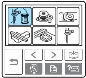
Displays simple explanations of setting upper thread / bobbin winding / setting bobbin thread / embroidery unit attachment / embroidery frame attachment / needle replacement on the LCD.
1 Turn on the machine.
The LCD comes on.
2 Press ? (Help key) on the operation panel.
The help screen appears.
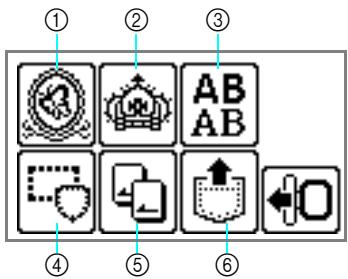
3 Press the item to be displayed.
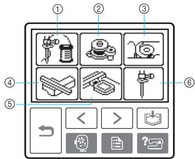
① Upper threading
② Bobbin winding
③ Bobbin installation
④ Embroidery unit attachment
⑤ Embroidery frame attachment
⑥ Needle replacement
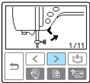
The first screen describing the procedure for the selected topic appears.
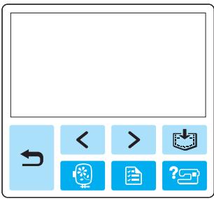
- Press (Back key) to return to the item selection screen.
4 Press > (Next page key) to switch to the next page.
Press < (Previous page key) to return to the previous page.
☐ Example: Upper threading
•
•
•
•
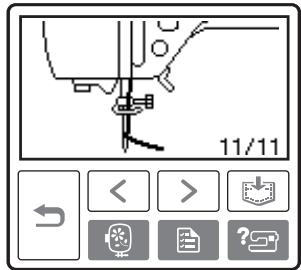
5 After you finish checking, press key) two times. (Back
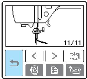
The initial stitch screen appears again.

Note
- For details on each topic, refer to the corresponding page in this Operation Manual.
Winding/Installing the Bobbin
This section describes how to wind the thread onto the bobbin, and then insert the bobbin thread.
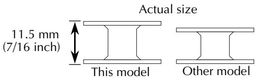
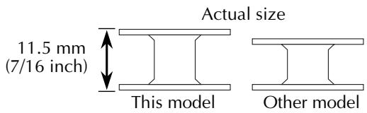
Bobbin precautions
Be sure to observe the following precautions concerning the bobbin.

CAUTION
- Only use the Bobbin (part code: SA156, SFB: XA5539-151) designed specifically for this machine. Use of any other bobbin may result in injuries or damage to the machine.
● The included bobbin was designed specifically for this machine. If bobbins from other models are used, the machine will not operate correctly. Use only the included bobbin or bobbins of the same type (part code: SA156, SFB: XA5539-151).
Winding the bobbin
Wind the thread around the bobbin to prepare the bobbin thread.
1 Turn on the machine.
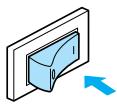
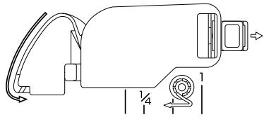
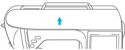
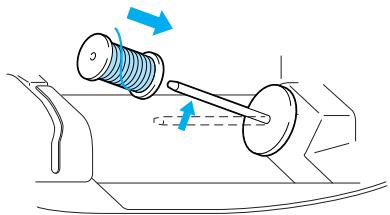
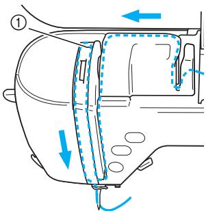
2 Open the top cover.

natural_image
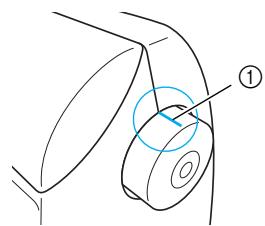
Line drawing of a vehicle's front panel with an arrow indicating direction (no text or symbols)3 Place the bobbin on the bobbin winder shaft so that the spring on the shaft fits into the notch in the bobbin.
Press down on the bobbin until it snaps into place.
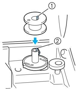
① Notch
② Bobbin winder shaft spring
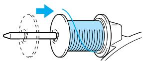
4 Slide the bobbin winder in the direction of the arrow until it snaps into place.
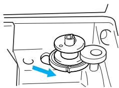
natural_image
Diagram of a mechanical component with a blue arrow indicating direction (no text or symbols)- (Start/stop button) lights up in orange.
5 Remove the spool cap that is inserted onto the spool pin.
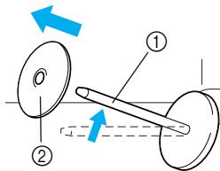
① Spool pin
② Spool cap
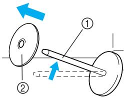
6 Place the spool of thread for the bobbin onto the spool pin.
Slide the spool onto the pin so that the spool is horizontal and the thread unwinds to the front at the bottom.
natural_image
Diagram of a mechanical assembly with a spring and shaft, showing motion direction (no text or symbols)- If the spool is not positioned so that the thread unwinds correctly, the thread may become tangled around the spool pin.
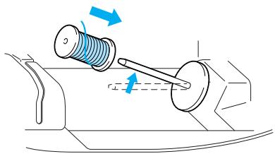
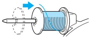
7 Slide the spool cap onto the spool pin.
Slide the spool cap as far as possible to the right, as shown, with the rounded side on the left.
natural_image
Diagram of a mechanical component with a shaft and threaded shaft, showing motion direction (no text or symbols)CAUTION
- If the spool or the spool cap is not installed correctly, the thread may become tangled around the spool pin, causing the needle to break.
- Three spool cap sizes are available, allowing you to choose a spool cap that best fits the size of spool being used. If the spool cap is too small for the spool being used, the thread may catch on the slit in the spool or the needle may break.
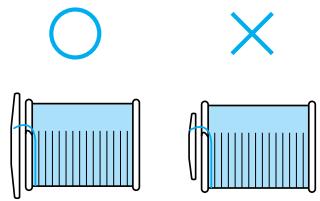
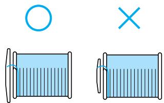
natural_image
Two identical illustrations of a blue cylindrical object with a circle above and a cross below, no text or symbols present.
Memo
- When embroidering with fine, cross-wound thread, use the small spool cap, and leave a small space between the cap and the spool.
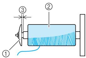
① Spool cap (small)
② Spool (cross-wound thread)
③ Space
- When using thread that winds off quickly, such as transparent nylon thread or metallic thread, place the spool net over the spool before placing the spool of thread onto the spool pin.
If the spool net is too long, fold it to fit the size of the spool.
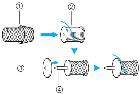
flowchart
graph TD
    A["Step ①: Cylinder"] --> B["Step ②: Axial fillet"]
    B --> C["Step ③: Axial shaft"]
    C --> D["Step ④: Axial shaft"]
① Spool net
② Spool
③ Spool cap
④ Spool pin
8 While holding the thread near the spool with your right hand, as shown, pull the thread with your left hand, and then pass the thread behind the thread guide cover and to the front.
① Thread guide cover
9 Pass the thread under the thread guide plate, and then pull it to the right.
① Thread guide plate
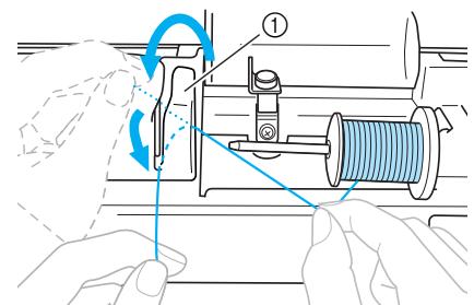
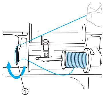
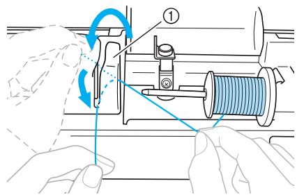
10 Pass the thread under the hook on the thread guide, and then wind it counterclockwise under the pretension disk.
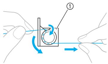
① Thread guide

Note
● Make sure that the thread passes under the pretension disk.
11 While holding the thread with your left hand, wind the thread that was pulled out clockwise around the bobbin five or six times with your right hand.
natural_image
Illustration of a hand holding a mechanical component with a blue arrow indicating rotation (no text or symbols)
Note
● Make sure that the thread between the spool and the bobbin is pulled tight.
- Be sure to wind the thread clockwise around the bobbin, otherwise the thread will become wrapped around the bobbin winder shaft.
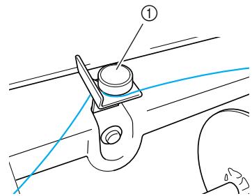
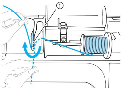
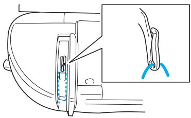
12 Pass the end of the thread through the guide slit in the bobbin winder seat, and then pull the thread to the right to cut it.
① Guide slit in bobbin winder seat (with built-in cutter)

CAUTION
- Be sure to cut the thread as described. If the bobbin is wound without cutting the thread using the cutter built into the slit in the bobbin winder seat, the thread may become tangled in the bobbin or the needle may bend or break when the bobbin thread starts to run out.
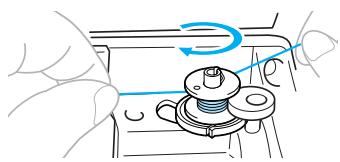
13 Press ⏻ (Start/stop button) once to start winding the bobbin.
① Start/stop button
- When the bobbin winding becomes slow, press ⏻ (Start/stop button) once to stop the machine.

CAUTION
- When the bobbin winding becomes slow, stop the machine, otherwise the machine may be damaged.
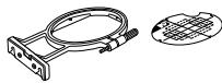
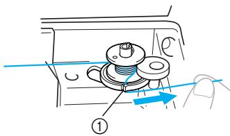
14 Use scissors to cut the end of the thread wound around the bobbin.
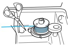
natural_image
Line drawing of a sewing machine with scissors, spool, and base mount (no text or symbols)15 Slide the bobbin winder shaft to the left, and then remove the bobbin from the shaft.
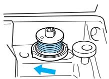
natural_image
Diagram of a mechanical component with a blue arrow indicating direction (no text or symbols)16 Remove the spool for the bobbin thread from the spool pin, and then close the top cover.

Memo
- When the machine is started or the handwheel is turned after winding the bobbin, the machine will make a clicking sound; this is not a malfunction.
Installing the bobbin
Install the bobbin wound with thread.

CAUTION
- Use a bobbin that has been correctly wound with thread, otherwise the needle may break or the thread tension will be incorrect.
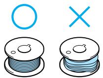
natural_image
Illustration of two spools of blue wire with a circle and an 'X' symbol above (no text or labels)● The bobbin was designed specifically for this machine. If bobbins from other models are used, the machine will not operate correctly. Use only the included bobbin or bobbins of the same type (part code: SA156, SFB: XA5539-151).
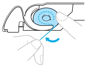
1 Slide the bobbin cover latch to the right.
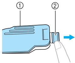
① Bobbin cover
② Latch
The bobbin cover opens.
2 Remove the bobbin cover.
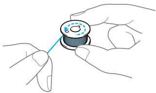
3 Hold the bobbin with your right hand and hold the end of the thread with your left.
natural_image
Illustration of hands holding a spool with a blue pointer (no text or symbols)- Be careful not to drop the bobbin.
4 Insert the bobbin into the bobbin case so that the thread unrolls to the left.
natural_image
Illustration of a hand holding a circular component with a blue line, no text or symbols present- Be sure to insert the bobbin correctly.

CAUTION
- Be sure to install the bobbin so that the thread unwinds in the correct direction, otherwise the thread may break or the thread tension will be incorrect.

Memo
● The order that the bobbin thread should be passed through the bobbin case is indicated by marks around the bobbin case. Be sure to thread the machine as indicated.
natural_image
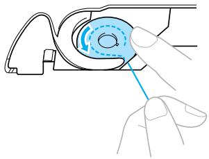
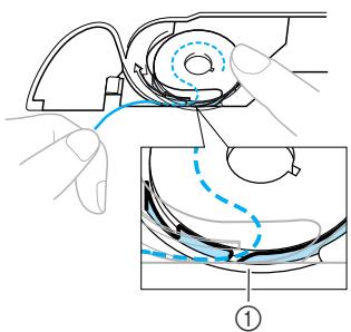
Technical line drawing of a mechanical device with no visible text or symbols5 Lightly hold down the bobbin with your right hand, and then guide the thread as shown with your left hand.
natural_image
Illustration of hands operating a mechanical device with a blue circular component and rotation arrow (no text or symbols)
CAUTION
- When installing the bobbin, be sure to hold it down with your finger. If the bobbin is not correctly installed, the thread tension will be incorrect.

Pass the thread through the slot as shown, and then pull the thread out toward the front.
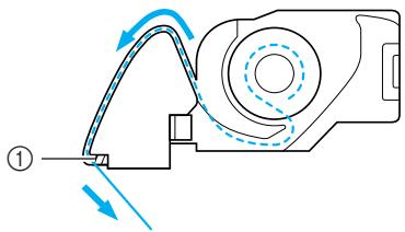
natural_image
Diagram of a mechanical device with directional arrows indicating motion or force (no text or symbols)① Cutter
The cutter cuts the thread.

Note
● Make sure that the thread is correctly inserted through the tension-adjusting spring of the bobbin case. If it is not inserted correctly, reinsert the thread.
① Tension-adjusting spring

Reattach the bobbin cover.
Insert the tab in the lower-left corner of the bobbin cover, and then lightly press down on the right side.
The lower threading is finished.
Next, thread the upper thread. Continue with the procedure in "Upper Threading" (page 30).

Memo
- You can start embroidering without pulling up the bobbin thread.
Upper Threading
This section describes how to position the spool for the upper thread, and then thread the needle.

CAUTION
- When threading the upper thread, carefully follow the instructions. If the upper threading is not correct, the thread may become tangled or the needle may bend or break.
About the spool of thread
Information about the spools of thread is described below.

CAUTION
- Three spool cap sizes are available, allowing you to choose a spool cap that best fits the size of spool being used. If the spool cap is too small for the spool being used, the thread may catch on the slit in the spool or the needle may break.
Threading the upper thread
Set the spool of thread on the spool pin, and then thread the machine.
1 Turn on the machine.
2 Raise the presser foot lever to raise the presser foot.
① Presser foot lever

Note
- If the presser foot is not raised, the machine cannot be threaded.
3 Press ⏻ (Needle position button) once or twice to raise the needle.
① Needle position button
The needle is correctly raised when the mark on the handwheel is at the top, as shown below. Check the handwheel and, if this mark is not at this position, press ⏻ (Needle position button) until it is.
① Mark on handwheel
4 Open the top cover.
natural_image
Line drawing of a vehicle dashboard with an upward arrow indicating motion (no text or symbols)5 Remove the spool cap that is inserted onto the spool pin.
① Spool pin
② Spool cap
6 Place the spool of thread onto the spool pin.
Slide the spool onto the pin so that the spool is horizontal and the thread unwinds to the front at the bottom.
natural_image
Diagram of a mechanical assembly with a spring and shaft, showing motion direction (no text or symbols)CAUTION
- If the spool or the spool cap is not positioned correctly, the thread may become tangled around the spool pin or the needle may break.
7 Slide the spool cap onto the spool pin.
Slide the spool cap as far as possible to the right, as shown, with the rounded side on the left.
natural_image
Diagram of a mechanical component with a blue cylindrical shaft and dashed circular motion arrow (no text or symbols)8 While holding the thread lightly with your right hand, pull the thread with your left hand, and then pass the thread behind the thread guide cover and to the front.
① Thread guide cover
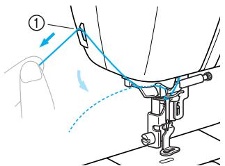
9 Pass the thread under the thread guide plate, and then pull it up.
① Thread guide plate
10 While using your right hand to lightly hold the thread passed under the thread guide plate, pass the thread through the guides in the order shown below.
① Shutter

Note
- If the embroidery foot has been lowered and the shutter is closed, the machine cannot be threaded. Be sure to raise the embroidery foot and open the shutter before threading the machine. In addition, before removing the upper thread, be sure to raise the embroidery foot and open the shutter.
● This machine is equipped with a window that allows you to check the position of the take-up lever. Look through this window and check that the thread is correctly fed through the take-up lever.
natural_image
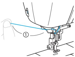
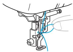
Line drawing of a car seatbelt with a magnified inset showing the cable being held (no text or symbols)11 Pass the thread behind the needle bar thread guide.
The thread can easily be passed behind the needle bar thread guide by holding the thread in your left hand, then feeding the thread with your right hand, as shown.
natural_image
Technical line drawing of a sewing machine needle and fabric connection (no text or symbols)① Needle bar thread guide
Threading the needle
This section describes how to thread the needle.

Memo
● The needle threader can be used with sewing machine needles 75/11 through 100/16.
- Thread with a thickness of 130/20 or thicker cannot be used with the needle threader.
- If the needle threader cannot be used, refer to "Threading the needle manually (without using the needle threader)" (page 34).
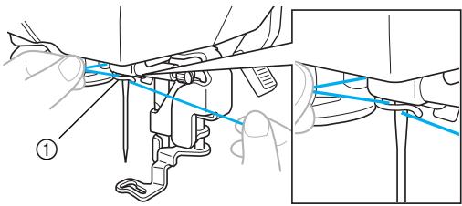
1 Pull the end of the thread passed through the needle bar thread guide to the left, and then pass the thread through the thread guide disk from the front.
① Thread guide disk
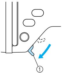
2 Cut the thread with the cutter on the left side of the machine.
① Cutter

Note
- If the thread is pulled through and cannot be cut correctly, lower the embroidery foot so that the thread is held in place before cutting the thread. If this operation is performed, skip step 3.
- When using thread that quickly winds off the spool, such as metallic thread, it may be difficult to thread the needle if the thread is cut.
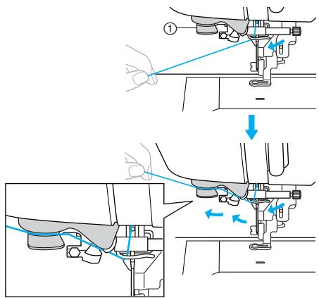
Therefore, instead of using the thread cutter, pull out about 80 mm (approx. 3 inches) of thread after passing it through the thread guide disks (marked "7").
① 80mm or more
3 Lower the presser foot lever to lower the embroidery foot.
① Presser foot lever
4 Lower the needle threader lever on the left side of the machine until it clicks, and then slowly return the lever to its original position.
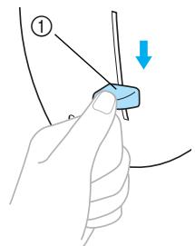
① Needle threader lever
The thread is passed through the eye of the needle.

Note
- If the needle was not completely threaded, but a loop in the thread was formed in the eye of the needle, carefully pull the loop through the eye of the needle to pull out the end of the thread.
natural_image
Mechanical assembly diagram showing a lever mechanism with blue guide lines (no text or labels)
CAUTION
- When pulling out the thread, do not pull it with extreme force, otherwise the needle may break or bend.
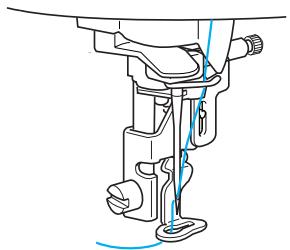
5 Raise the presser foot lever, pass the end of the thread through the embroidery foot hole.
natural_image
Technical line drawing of a sewing machine needle and screw (no text or symbols)The upper threading is finished.
Now that the upper threading and the lower threading are finished, you are ready to start embroidering.

Note
- If the needle is not raised, the needle threader cannot thread the needle. Be sure to press ⏻ (Needle position button) to raise the needle before using the needle threader.
Threading the needle manually (without using the needle threader)
When using special thread, thread with a thickness of 130/20 or thicker which cannot be used with the needle threader, thread the needle as described below.
1 Thread the machine to the needle bar thread guide.
- For details, refer to "Threading the upper thread" (page 30).
2 Lower the presser foot lever.
① Pressor foot lever
3 Pass the thread through the eye of the needle from front to back.
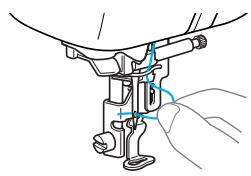
natural_image
Technical line drawing of a mechanical assembly with hands operating a component (no text or symbols)4 Raise the presser foot lever, pass the end of the thread through the embroidery foot hole.
Replacing the Needle
This section describes how to replace the needle.
Needle precautions
Be sure to observe the following precautions concerning the handling of the needle. Failure to observe these precautions is extremely dangerous, for example, if the needle breaks and fragments are dispersed. Be sure to read and carefully follow the instructions below.

CAUTION
- Only use home sewing machine needles. Use of any other needle may bend the needle or damage the machine.
● Never use bent needles. Bent needles can easily break, possibly resulting in injuries.
Checking the needle
Embroidering with a bent needle is extremely dangerous since the needle may break while the machine is being operated.
Before using the needle, place the flat side of the needle on a flat surface and check that the distance between the needle and the flat surface is even.
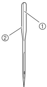
① Flat side
② Needle type marking

CAUTION
- If the distance between the needle and the flat surface is not even, the needle is bent. Do not use a bent needle.
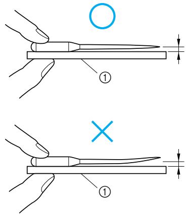
① Flat surface
Replacing the needle
Replace the needle as described below. Use the screwdriver and a needle that has been determined to be straight according to the instructions in “Checking the needle” (page 35).
1 Press ⏻ (Needle position button) once or twice to raise the needle.
① Needle position button
2 Turn off the machine.
CAUTION
- Before replacing the needle, be sure to turn off the machine, otherwise injuries may occur if ⏻ (Start/stop button) is accidentally pressed and the machine starts embroidering.
3 Lower the presser foot lever.
① Presser foot lever
4 Place fabric or paper under the embroidery foot to cover the hole in the needle plate.
Note
● Before replacing the needle, cover the hole in the needle plate with fabric or paper to prevent the needle from falling into the machine.
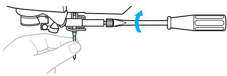
5 Hold the needle with your left hand, and then use a screwdriver to turn the needle clamp screw toward you (counterclockwise) to remove the needle.
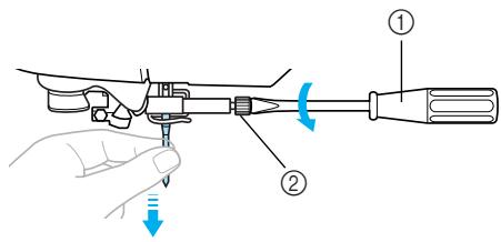
① Screwdriver
② Needle clamp screw
- Do not apply a strong force when loosening or tightening the needle clamp screw, otherwise certain parts of the machine may be damaged.
natural_image
Diagram of a screwdriver with a blue-handled tool and a blue screwdriver below (no text or symbols)6 With the flat side of the needle toward the rear of the machine, insert the needle until it touches the needle stopper.
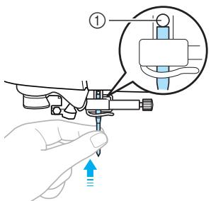
① Needle stopper
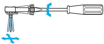
7 While holding the needle with your left hand, use the screwdriver to tighten the needle clamp screw.
natural_image
Line drawing of a hand using a tool to adjust or install a screwdriver (no text or symbols present)CAUTION
- Be sure to insert the needle until it touches the needle stopper and securely tighten the needle clamp screw with the screwdriver, otherwise the needle may break or damage may result.
2
EMBROIDERY
The steps for embroidering are described in this chapter.
Embroidering Neatly 40
What to prepare......40
Preparing the Fabric 42
Attaching a stabilizer material to the fabric 42
Setting the fabric in the embroidery frame ....43
Attaching the Embroidery Frame......47
Attaching the embroidery frame ....47
Removing the embroidery frame....48
Selecting Embroidery Patterns......49
Copyright information......49
Embroidery pattern types......49
LCD (liquid crystal display) operation......50
Selecting characters ...... 52
Selecting an embroidery pattern ....53
Selecting a frame pattern ....54
Using an embroidery card (sold separately)....55
Embroidering......56
Embroidering attractive finishes .....56
Embroidering a pattern....57
Appliquéing....59
Editing and Saving Patterns ......61
Adjusting the layout ......61
Storing patterns......63
Adjusting the thread tension......64
Resewing......65
Thread runs out partway through a design....65
Stopping while embroidering .....66
Bobbin Case Adjustment ......68
Correct tension....68
Bobbin thread is loose....68
Bobbin thread is tight....68
Embroidering Neatly
This section describes the preparations and basic procedures for embroidering.
What to prepare
The following is necessary for embroidering.
Fabric
Prepare the fabric for embroidery. Prepare a piece of fabric a little larger than the embroidery frame that matches the size of the pattern you want to embroider.

Note
● Always use stabilizer for embroidery projects, especially when embroidering on lightweight or stretch fabrics. Not using a stabilizer may result in poor quality embroidery designs.

CAUTION
- Do not embroider fabrics that are too thick. To check the fabric thickness, attach the embroidery frame to the embroidery unit, and use ⏻ (Needle position button) to raise the needle. If there is space between the embroidery foot and the fabric, the fabric can be embroidered. If there is not space, do not embroider the fabric. Otherwise, the needle may break, resulting in injury.
- Be careful when embroidering overlapping patterns. The needle may not easily pierce the fabric, causing the needle to break.
■ Stabilizer material
Attach a stabilizer material for embroidery to the fabric to prevent poor quality embroidery designs.
We recommend stabilizer material for embroidery. Use a water soluble sheet on thin materials like organdy and fabrics with a nap like towels. For details, refer to “Optional accessories” (page 7).
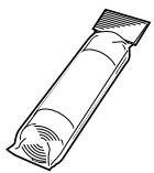
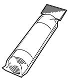
■ Embroidery thread
For the upper thread, use the embroidery thread or country thread.
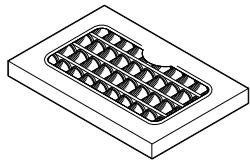
natural_image
Isometric line drawing of a rectangular electronic component with internal grid structure (no text or symbols)For the bobbin thread, use the embroidery bobbin thread. For details, refer to “Optional accessories” (page 7).

Note
- For good quality embroidery designs be sure to use embroidery thread designed for embroidery machines.
● Before starting to embroider, be sure there is enough bobbin thread. If you continue embroidering when the bobbin thread is low, the thread may become tangled.
Needle
Use a 75/11 home sewing machine needle. When embroidering on thick fabrics such as denim, use a 90/14 home sewing machine needle.

Memo
● A 75/11 needle is already installed when the machine is purchased.
- When replacing the needle, refer to "Replacing the needle" (page 36).
■ Other
Embroidery frames “small”, “medium” and “extra large (multi-position)” are optional. For details, refer to “Optional accessories” (page 7).
Preparing the Fabric
After attaching a stabilizer material to the embroidery fabric, it is stretched on an embroidery frame.
Attaching a stabilizer material to the fabric
Attach a stabilizer material for embroidery to the fabric to prevent poor quality embroidery designs.

Memo
- We recommend the stabilizer material for embroidery. Use a water soluble stabilizer on thin materials like organdy and fabrics with a nap like towels. For details, refer to "Optional accessories" (page 7).

Note
● Always use stabilizer material for embroidery with stretch fabrics, thin fabrics, fabrics with a loose weave and fabrics where stitches easily contract.

CAUTION
● Always use stabilizer material for embroidery projects. The needle may break or bend if you embroider without using a stabilizer material for thin fabrics or stretch fabrics. Furthermore, the pattern may not turn out correctly.
1 Prepare stabilizer material that is larger than the embroidery frame being used.
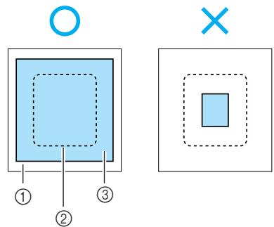
① Fabric
② Size of embroidery frame
③ Stabilizer material
2 If you are using stabilizers with adhesive, place the adhesive surface of the stabilizer material against the wrong side of the fabric, and iron it with a steam iron.
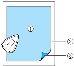
① Stabilizer material
② Fabric (wrong side)
③ Attached surface
□ When it cannot be ironed or placed in the hoop.
For fabrics, such as towels, which cannot be ironed or for embroidering in places where ironing is difficult, place the stabilizer material under the fabric, and stretch the fabric in the embroidery frame without attaching the stabilizer.
Setting the fabric in the embroidery frame
The fabric is stretched in the embroidery frame. If the fabric is loose, the quality of the embroidery pattern may be poor. Put the fabric in the frame without slack following the steps below. Have a fabric with a stabilizer material attached and the embroidery frame (medium, small, large or extra large (multi-position)) ready.
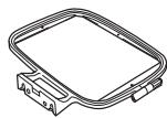
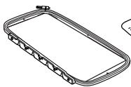
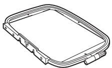
■ Embroidery frame (large)
Embroidery can be done in an area with a height of up to 18 cm (7 inches) and a width of up to 13 cm (5 inches). This is used to embroider multiple patterns without changing the fabric position in the frame.
natural_image
Technical line drawing of a rectangular mechanical component with mounting flanges (no text or symbols)■ Embroidery frame (medium)[option]
Patterns with a height of up to 10 cm (4 inches) and a width of up to 10 cm (4 inches) can be embroidered.
![BROTHER INNOV-IS 700E - ■ Embroidery frame (medium)[option] - 1](/content/2025/01/74636/images/6e35fcf1eaa0622b696826e240ee4aa45fe62e73c3d73495f3cb591a8f598819.jpg)
■ Embroidery frame (small)[option]
Patterns with a height of up to 2 cm (1 inch) and a width of up to 6 cm (2-1/2 inches) can be embroidered. This is used for letters and other small embroidery.
![BROTHER INNOV-IS 700E - ■ Embroidery frame (small)[option] - 1](/content/2025/01/74636/images/c3eae7ddcf322d4febd82e03f28845f472eb1d6654776ab84a9016bff5f9bdc2.jpg)
- There are patterns for which embroidery frame (small) cannot be used.
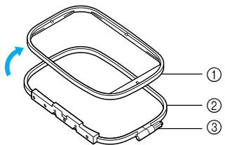
■ Embroidery frame (extra large (multi-position)) [option]
Embroidery can be done in an area with a height of up to 30 cm (12 inches) and a width of up to 13 cm (5 inches). This is used to embroider connected or combined characters or patterns, or large patterns.
![BROTHER INNOV-IS 700E - ■ Embroidery frame (extra large (multi-position)) [option] - 1](/content/2025/01/74636/images/fc7a8e923054e20e924333ff343e889b8bb9d4ce3fbfb53e7c9288783a3d4234.jpg)
natural_image
Line drawing of a rectangular electronic component with multiple connectors and a small top connector (no text or symbols)![BROTHER INNOV-IS 700E - ■ Embroidery frame (extra large (multi-position)) [option] - 2](/content/2025/01/74636/images/3aebe6160f2faf7792933066a2f608fd5ba50b2f43dddd00be6b87d402d145d2.jpg)
CAUTION
- Use the embroidery frame that matches the size of the pattern being embroidered. Otherwise, the embroidery frame may be hit by the embroidery foot and cause injury or needle breakage.
1 Loosen the embroidery frame adjustment screw and remove the inner and outer frames, placing the outer frame on a flat surface.
Separate the inner and outer frame by removing inner frame upward.
① Inner frame
② Outer frame
③ Adjustment screw
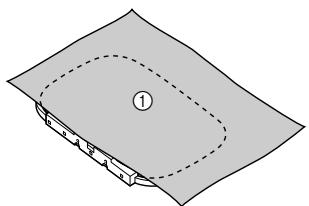
2 Place the fabric with the stabilizer material on top of the outer frame.
Have the right side of the cloth up.
natural_image
Diagram of a folded paper or sheet with a dashed oval outline and numbered label (1), no readable text or symbols present.① Right side
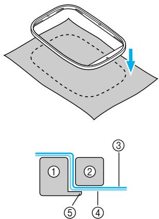
3 Press the inner frame in from the top of the fabric.
Line up △ on the inner frame and ▽ on outer frame.
4 Tighten the adjustment screw by hand just enough to secure the fabric.
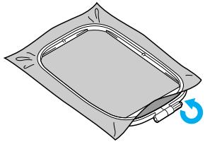
natural_image
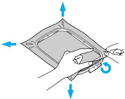
Illustration of a gray plastic bag with a blue circular arrow indicating rotation (no text or symbols)5 Gently remove the fabric from the frame without loosening the adjustment screw.

natural_image
Illustration of hands holding a rectangular object with a blue arrow indicating rotation (no text or symbols)
Memo
● This precautionary step will help reduce pattern distortion while embroidering.
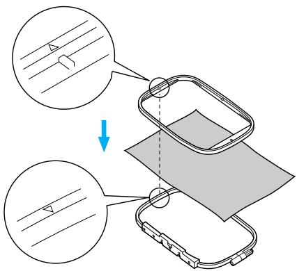
6 Press the inner frame in from the top of the fabric again, lining up △ on the inner frame and ▽ on outer frame.
① Outer frame
② Inner frame
③ Fabric (right side)
④ Stabilizer material
⑤ Ledge of outer frame
- Press down firmly until the inner frame is securely pressed against the ledge of the outer frame.
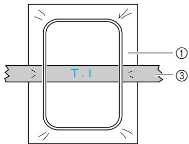
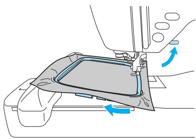
7 Tighten the adjustment screw while removing any slack in the fabric by hand. The goal is to have a drum-like sound when the stretched fabric is struck lightly.
natural_image
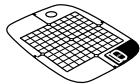
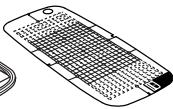
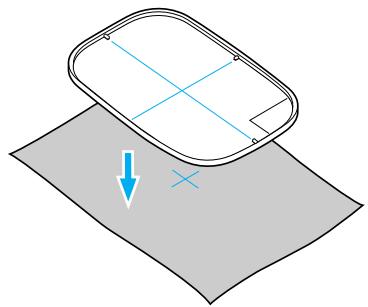
Illustration of a hand holding a folded paper or plastic sheet with blue directional arrows indicating rotation (no text or symbols)■ Using embroidery sheets
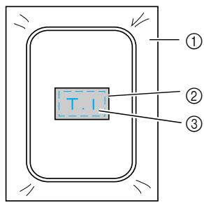
If the embroidery sheet attached to the embroidery frame is used, the pattern can be embroidered in exactly the right position on the fabric.
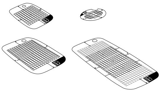
natural_image
Line drawings of four different mobile phone modules with grid patterns, shown from top to bottom (no text or symbols)1 Make a mark with a chalk pen at the center of the position for the pattern to be embroidered.
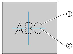
① Embroidery pattern
② Mark
2 Place the embroidery sheet on the inner frame.
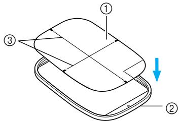
① Embroidery sheet
② Inner frame
③ Embroidery sheet base lines
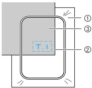
3 Line the mark on the fabric up with the base line on the embroidery sheet.
natural_image
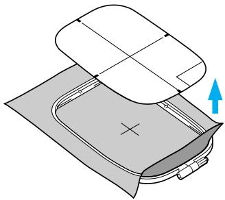
Diagram showing a 3D object with coordinate axes and a blue arrow pointing to it, placed on a gray surface (no text or symbols)4 Place the inner frame with the fabric on the outer frame and stretch the fabric.
- For details, refer to page 43.
Remove the embroidery sheet.
natural_image
Diagram of a mechanical component with a blue upward arrow indicating motion or force (no text or symbols present)■ Embroidery on fabrics that cannot be stretched on an embroidery frame
When small pieces of fabric that cannot be stretched on an embroidery frame or thin pieces like ribbon are being embroidered, use stabilizer material as a base to stretch on the frame. We recommend stabilizer material for all embroidery.
① Stabilizer material
② Tack or spray glue
③ Fabric
After completing the embroidery, remove the stabilizer material carefully.
Attaching the Embroidery Frame
This section describes how to attach the embroidery frame.
Attaching the embroidery frame
1 Wind the embroidery bobbin thread onto the bobbin and set it into the bobbin case.
- For details, refer to "Winding/Installing the Bobbin" (page 24).
2 Raise the presser foot lever.
① Presser foot lever
3 Pass the embroidery frame under the embroidery foot while raising the presser foot lever even further.
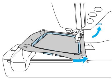
natural_image
Diagram of a mechanical component with blue directional arrows indicating movement or force (no text or symbols present)
CAUTION
- Do not hit the needle with your finger or the embroidery frame. It may cause injury or needle breakage.
4 While lightly holding the lever on the frame holder to the left, align the two pins on the embroidery frame holder with the mounting brackets on the frame, and then press the frame into the embroidery frame holder until a click is heard.
After pressing the front mounting bracket onto the pin so that it clicks into place, press the back mounting bracket into place.
① Lever
① Mounting brackets
② Pins
natural_image
Line drawing of a hand holding a tool with a blue arrow indicating direction (no text or symbols)
Note
- Be sure to insert both pins. If only the forward or the back pin is inserted, the pattern may not turn out correctly.

CAUTION
- Correctly set the embroidery frame into the embroidery frame holder. Otherwise, the embroidery foot may hit the embroidery frame, resulting in injury.
Removing the embroidery frame
Make sure that the machine is completely stopped and follow the instructions below.
1 Raise the presser foot lever.

① Presser foot lever
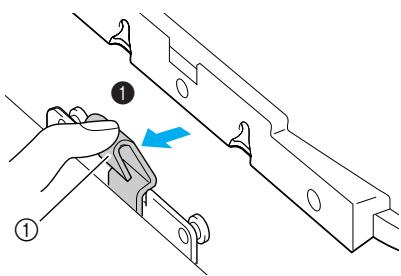
2 While pushing the lever of the embroidery frame holder to the left, lift the embroidery frame up to remove it.
Remove the back mounting bracket from the pin, and then remove the front mounting bracket from the pin.
① Lever
① Mounting brackets
② Pins
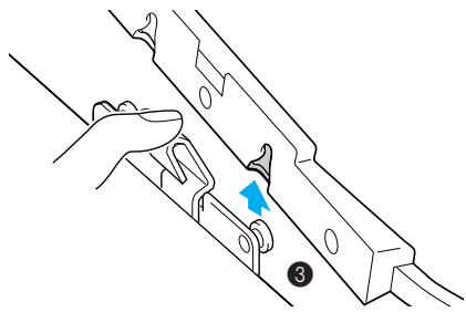
natural_image
Illustration of a hand holding a metal bracket with a blue arrow pointing to a clip, labeled with number 3 (no text or symbols on the diagram itself)3 Pass the embroidery frame under the embroidery foot while raising the presser foot lever even further.
natural_image
Mechanical assembly diagram showing a component with blue directional arrows indicating motion or force (no text or symbols present)CAUTION
- Do not hit the needle with your finger or the embroidery frame. It may cause injury or needle breakage.
Selecting Embroidery Patterns
This section provides details on the various types of embroidery patterns available and the procedure for selecting a pattern.
Copyright information
The patterns stored in the machine and embroidery cards are intended for private use only. Any public or commercial use of copyrighted patterns is an infringement of copyright law and is strictly prohibited.
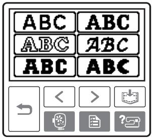
Embroidery pattern types
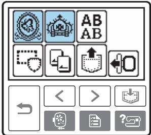
An embroidery pattern can be selected from the following types available.
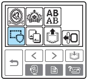
① Embroidery patterns
② Additional embroidery patterns
③ Alphabet patterns
④ Frame patterns
⑤ Embroidery card
⑥ Patterns stored in the machine's memory
■ Embroidery patterns (Embroidery patterns/Additional embroidery patterns)
There are total 136 patterns. The patterns are completed by changing the upper thread according to the instructions displayed on the screen.
- For details, refer to “Selecting an embroidery pattern” (page 53).
■ Alphabet patterns
There are 6 types of characters (European characters); upper case/lower case/numbers/symbols.
- For details, refer to "Selecting characters" (page 52).
Frame patterns
10 shapes, such as squares and circles, can be combined with 12 stitch types.
- For details, refer to "Selecting a frame pattern" (page 54).
■ Embroidery card (sold separately)
Patterns from an embroidery card can be embroidered.
- For details, refer to "Using an embroidery card (sold separately)" (page 55).
■ Patterns stored in the machine's memory
Patterns, such as frequently used character combinations, can be stored in the machine's memory to be recalled later and embroidered. Patterns consisting of up to 12 patterns or 512 KB can be stored.
- For details, refer to "Storing patterns" (page 63).
LCD (liquid crystal display) operation
The LCD (liquid crystal display) is operated using the operation keys on the operation panel. The use of the keys for embroidery will be explained below.
■ Operation keys

Returns to the previous screen.

When there are patterns that are not displayed on the screen (when < or > is displayed), the previous patterns/subsequent patterns are displayed.

Returns to the type selection screen. The selected pattern is cancelled.

Press this key to adjust language or change the thread color display or other settings.
Press 📄 (Settings key).
![[NAME OF COLOR] [ ---- ]](/content/2025/01/74636/images/4ef14b3b9d43eac4aef2ed831f92d73727600c4d3bee1d5d50de0087b7ec21ad.jpg)
NAME OF COLOR: Typical color name
TIME: Time required for embroidering
NEEDLE COUNT: Needle progress number
123: Select from the following thread color number sets
• EMBROIDERY (POLYESTER) THREAD#
• COUNTRY (COTTON) THREAD#
• MADEIRA POLY THREAD#
• MADEIRA RAYON THREAD#
- SULKY THREAD#
• ROBISON-ANTON POLY THREAD#
![[ mm ] EMBROIDERY TENSION MAX EMBROIDERY SPEED 650 350 SPM 5PM](/content/2025/01/74636/images/851b12beea061d8a37b2a48b8ef89ec3c009217a9b426b72c93db35ab8593b58.jpg)
DISPLAY UNIT
The measurement units that are displayed can be selected. [mm/inch]
EMBROIDERY TENSION
The thread tension for embroidering can be adjusted. [-8 to +8]
MAX EMBROIDERY SPEED (SPM)
The maximum embroidering speed can be selected. [650SPM/350SPM]
LCD button

When a specific pattern is selected, press this key and then, press ▶ to switch the display. The embroidery settings such as the specified character string and color are confirmed.

Press this key to change the thread settings.
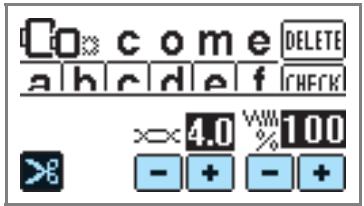

Press this key to select or cancel programmed thread cutting.

Press ☐ or ☐ to adjust the thread tension.

Press + or - to change the thread density (alphabet and frame patterns only).

Press this key to adjust the pattern.
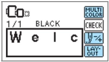

Press this key when you want to change the color character by character in character embroidery. Since the machine stops at the end of each character, the upper thread is changed as you embroider. Press this key again to cancel multi-color.

The needle progresses one color or one stitch (if pressed continuously, 9 stitches to 20 stitches) at a time and changes the position for starting the embroidery. This is used when a specific color is not embroidered or when restarting the machine after power has been turned off in the middle of the operation.

Back one color


Back one stitch

Forward one color
Forward one stitch
- For details, refer to "Resewing" (page 65).

The position of the pattern within the embroidery frame can be checked, and the size and angle can be changed.
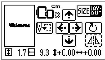
- For details, refer to "Adjusting the layout" (page 61).

Memo
● Keys that appear surrounded with a dotted line cannot be used.
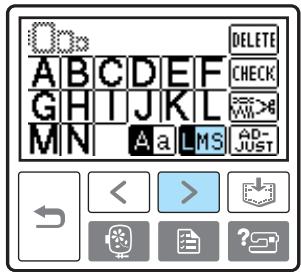
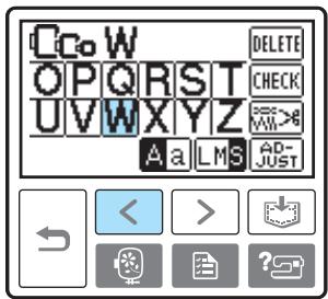
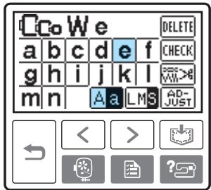
Selecting characters
Specify the characters for embroidery.

Memo
- When "The pattern is too large for the embroidery frame." is displayed, no more characters can be entered.
● Characters of different styles (sans serif, serif, and outline, etc.) cannot be combined.
1 Select the alphabet patterns.
2 Select the character style.
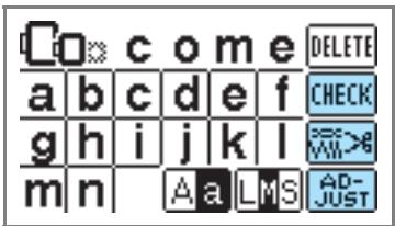
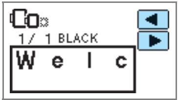
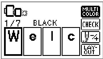
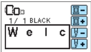
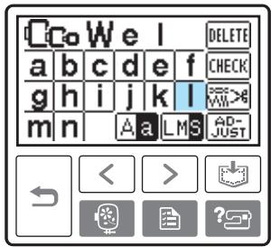
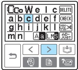
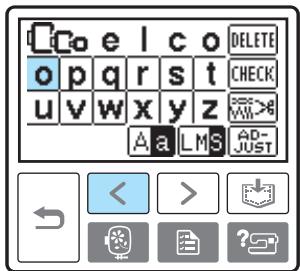
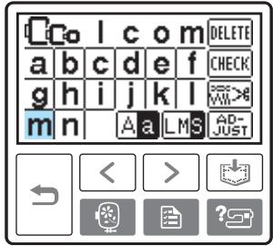
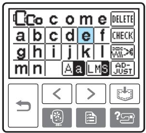
3 Select the characters. If a wrong character was selected, press DELETE.
Example: Welcome

Switch between uppercase/lowercase

Switch among large/medium/small sizes

Memo
- The alphabet pattern you created can be stored for later use. For details, refer to "Storing patterns" (page 63).
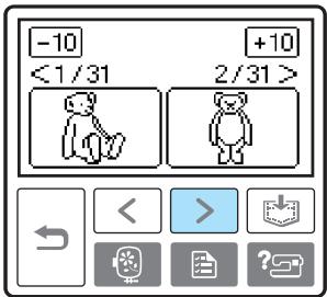
Selecting an embroidery pattern
There are total of 136 embroidery patterns, such as fruits and animals, stored in the machine's memory.

70 Embroidery patterns

66 Embroidery patterns

Memo
- Refer to "Embroidery Pattern Color Change Table" in the Quick reference guide for samples of completed patterns and the thread used.
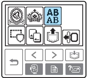
1 Select the type of the embroidery pattern.
The pattern selection screen is displayed.

Select the pattern.
Switch the screen using < (Previous page key) and > (Next page key).
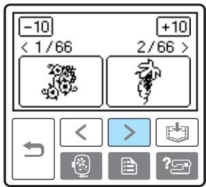
- When -10/+10 is pressed, the display of patterns moves backward/forward 10 patterns.
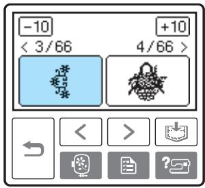
When a pattern is selected, it can be embroidered.
Selecting a frame pattern
10 shapes, such as squares and circles, can be combined with 12 stitch types.

Memo
- Refer to "Frame patterns" in the Quick reference guide for frame pattern shapes and stitches.
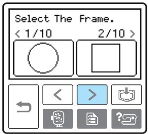
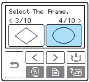
1 Press the frame pattern.
The frame shape selection screen is displayed.
2 Select the frame shape.
Switch the screen using < (Previous page key) > (Next page key), and select from the ten types.
The stitch selection screen is displayed.
Select the stitch.
Switch the screen using < (Previous page key) > (Next page key), and select from the 12 stitches.
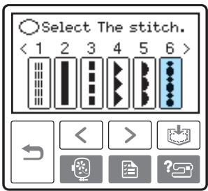
When a stitch is selected, it can be embroidered.
Using an embroidery card (sold separately)
If an embroidery card is used, you can embroider patterns other than the patterns stored in the machine. There are various cards with different themes.

Note
● Always turn off the machine to insert and remove embroidery cards.
- Insert the embroidery card into the embroidery card slot, facing it in the right direction.
- Do not put anything other than an embroidery card in the embroidery card slot.
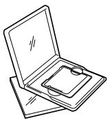
- When embroidery cards are not in use, keep them in their storage cases.
- Use only embroidery cards manufactured for this machine. Using unauthorized cards may cause your machine to operate incorrectly.
- Embroidery cards purchased in foreign countries may not work with your machine.
● Large patterns supplied on embroidery cards may be difficult to view on the screen.
1 Turn off the machine.
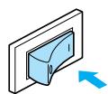
2 Insert the embroidery card in the embroidery card slot on the right side of the machine.
Face the arrow on the embroidery card toward you, and insert it in the direction of the arrow.
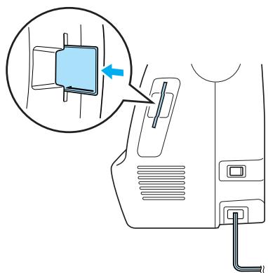
natural_image
Diagram of a car interior showing a blue box being inserted into a cable, with no text or symbols present.3 Turn on the machine.
4 Press the embroidery card on the screen.
The selection screen for the patterns stored in the card is displayed.
5 Select a pattern. The operation is the same as in “Selecting Embroidery Patterns” (page 49).
Embroidering
After the preparations are done, you can try embroidering. This section describes the steps for embroidering and appliquéing.
Embroidering attractive finishes
There are many factors that go into sewing beautiful embroidery. Using the appropriate stabilizer (page 42) and hooping the fabric in the frame (page 43) are two important factors mentioned earlier. Another important point is the appropriateness of the needle and thread being used. See the explanation of threads below.
| Thread | Upper thread | Use embroidery thread, or country embroidery thread intended for use with this machine. Other embroidery threads may not yield optimum results. |
| Bobbin thread | Use embroidery bobbin thread intended for use with this machine. For details, refer to “Optional accessories” (page 7). |

Memo
- If you use threads other than those listed above, the pattern may not turn out correctly.

Note
- Before embroidering, check that there is enough thread in the bobbin. If you continue embroidering without enough thread in the bobbin, the thread may tangle.
- Do not leave objects in the range of motion of the embroidery frame. The frame may strike the object and cause a poor finish to the embroidery pattern.
- When embroidering on large garments (especially jackets or other heavy fabrics), do not let the fabric hang over the table. Otherwise, the embroidery unit cannot move freely, and the pattern may not turn out as planned.
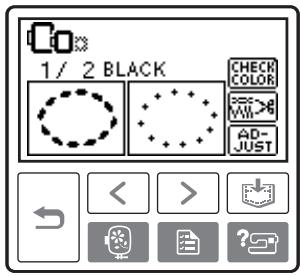
Embroidering a pattern
Embroidery patterns are embroidered with a change of thread after each color.
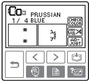
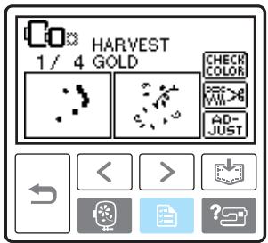
1 Prepare embroidery thread of the color shown on the screen.
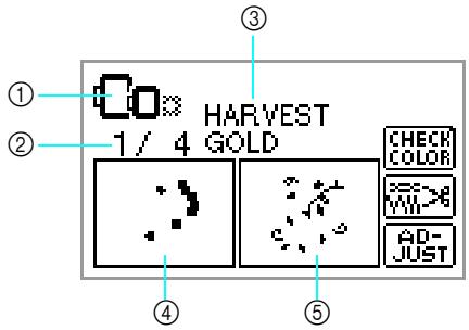
① Embroidery frames that can be used for embroidering
② Current color step/Number of colors in design
③ Current name of color
④ Current color part
⑤ Next color part
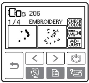
- The thread color number set displayed for the
thread colors can be changed. Press

(Settings key), and then change the setting in the settings screen. For details, refer to “LCD (liquid crystal display) operation” (page 50).
![[NAME OF COLOR] [ ---- ]](/content/2025/01/74636/images/9d54f67c92aeab7e2dca630f5dc022f28e53cee935737f3ba2ed0c78d60acf4b.jpg)
☐ Example: Embroidery thread number selected
![[ #123 ] [EMBROIDERY]](/content/2025/01/74636/images/c278a6aed21590096380d10995abe36927deca7b01494d73a533eec4975f6bfa.jpg)
2 Set the embroidery thread, thread the needle, then pass the end of the thread through the embroidery foot hole.
Give the thread a little slack.
natural_image
Line drawing of a sewing machine needle stitching a foot, with no text or symbols present- Refer to “Threading the upper thread” (page 30) and “Threading the needle” (page 32).

Note
● Before using the needle threader, be sure to lower the embroidery foot.

CAUTION
- If the thread is pulled too tight, the needle may break or bend.
- Do not let hands or objects hit the carriage while embroidering. The pattern may misalign.
3 Lower the presser foot lever.

① Presser foot lever
4 Press ⏻ (Start/stop button).
① Start/stop button
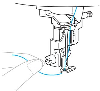
5 After progressing 5-6 stitches, press ⏻ (Start/stop button) to stop the machine.
6 Use scissors to cut the thread at the beginning of the stitching.
Cut the thread at the edge of the stitching.

natural_image
Line drawing of a sewing machine needle with scissors cutting the thread (no text or symbols)- If the thread is left at the beginning of the stitching, it may be sewn over as you continue embroidering the pattern, making it very difficult to deal with the thread after the pattern is finished. Trim the thread at the beginning.
7 Press ⏻ (Start/stop button) again.
The embroidery starts again and stops automatically with reinforcement after one color has been completed. When automatic thread cutting is set, the thread is cut.
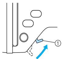
8 Press ⬆ (Thread cutter button) once.
natural_image
Pure diagram of a mechanical or electrical component with no text, numbers, or symbols① Thread cutter button
The needle is raised and the threads are cut.
CAUTION
- Do not press ⬆ (Thread cutter button) after threads have already been cut, otherwise the needle may break, the threads may become tangled or damage to the machine may occur.
- Do not press ⚠ (Thread cutter button) if there is no fabric under the embroidery foot or while the machine is embroidering, otherwise damage to the machine may occur.
9 Set up embroidery thread for the next color, and repeat steps 1 through 8.
10 Cut the excess thread.
When the last color is embroidered, "Finished sewing." will appear on the display. Press OK, and the display will return to the initial screen.
Memo
- For the automatic cutting setting, refer to "LCD (liquid crystal display) operation" (page 50).
Appliquéing
Prepare the base fabric and the appliqué fabric (appliqué piece). Press 📄 (Settings key), and set the thread color display to NAME OF COLOR, so "APPLIQUE MATERIAL", "APPLIQUE POSITION" and "APPLIQUE" are displayed on the screen.
1 Select an appliqué pattern.
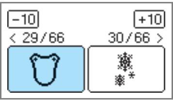
2 When "APPLIQUE MATERIAL" is displayed on the screen, apply iron-on stabilizer to the back of the appliqué piece fabric, and stretch it on the embroidery frame.
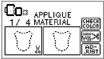
3 Lower the presser foot lever, and press (Start/stop button).
The cut-out for the appliqué piece is sewn, and the machine stops.
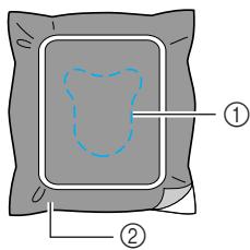
① Cut-out line
② Appliqué piece fabric
“APPLIQUE POSITION” will be displayed on the screen.
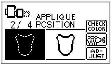
4 Remove the fabric from the embroidery frame, and cut it out along the cut-out line.
Cut carefully along the stitching and remove the thread.
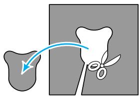
- If it is not cut right on the stitching, it will not be finished neatly.
5 Stretch the base fabric on the embroidery frame.
6 Set up the thread for appliquéing.
7 Lower the presser foot lever, and press (Start/stop button).
The position for the appliqué is stitched, and the machine stops.
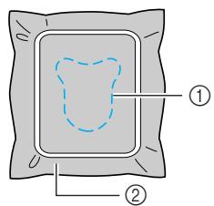
① Appliqué position
② Base fabric
“APPLIQUE” will be displayed on the screen.
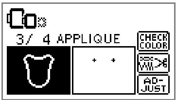
8 Apply a thin layer of fabric glue or spray adhesive to the back of the appliqué piece, and attach it in the appliqué position.
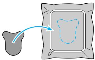
natural_image
Diagram showing a gray irregular shape transforming into a dashed blue square with an arrow (no text or symbols)9 Lower the presser foot lever, and press ⏻ (Start/stop button).
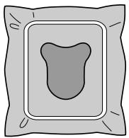
natural_image
Simple line drawing of a rounded rectangular package with a central teardrop shape (no text or symbols)
Note
- When "APPLIQUE MATERIAL", "APPLIQUE POSITION" and "APPLIQUE" are displayed, a specific color thread does not appear. Use a proper color thread to match the appliqué piece.
10 Follow the instructions on the screen, and change thread colors as you embroider.
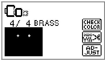
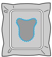
natural_image
Simple illustration of a gray square with a blue textured center and black border (no text or symbols)Editing and Saving Patterns
This section describes ways to edit, adjust, reposition and memorize patterns.
Adjusting the layout
The pattern is normally positioned in the center of the embroidery frame.
You can check the layout before starting embroidery and change the position and the size.

Memo
- Keys that appear surrounded with a dotted line cannot be used.
1 After selecting the embroidery pattern, press AD-JUST.
The embroidery screen is displayed.
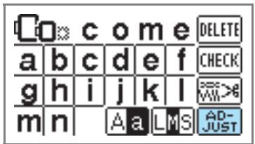
2 Press LAY-OUT.
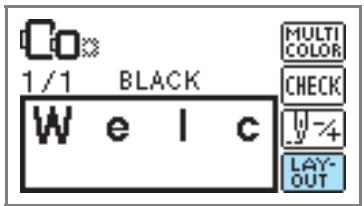
The layout screen is displayed.
3 Check and adjust the layout.
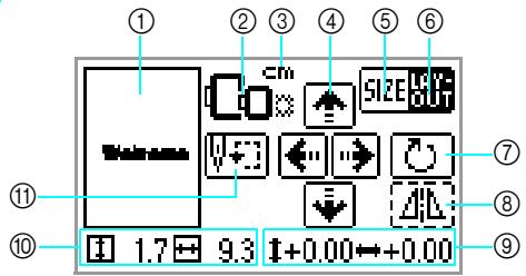
① Layout within the frame
② Available embroidery frames
③ Display unit (cm/INCH)
④ Change position keys
⑤ Size key
⑥ Layout key
⑦ Rotation key
⑧ Horizontal mirror image key
⑨ Distance from the center
⑩ Embroidery size
⑪ Starting point key

Embroidery frame size
These flash if the pattern was resized, the layout was adjusted, or the recommended embroidery frame size was changed. Embroidery frame icons that appear in gray cannot be used.

Size key
Increases/decreases the size of the pattern. Press LAY-OUT to return to the previous screen.
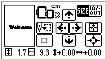

Decreases size

Returns to original size
Returns to center position (when the pattern was moved with the change position key)

Increases size
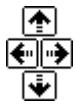
Change position keys
Moves the embroidery position up, down, left and right.

Memo
- If you make a note of the values in the lower part of screen when you change the size and position, you can embroider with the same size and layout even if you have to turn the power back on in the middle of your work.

Layout key
Press this key to move to rotation screen.
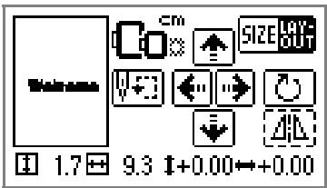

Rotation key
Rotates the pattern one degree, 10 degrees or 90 degrees at a time.
- Press (Back key) to return to the previous screen.
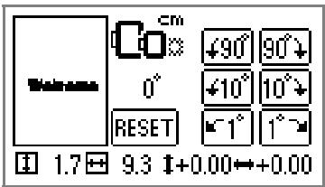

Rotates the pattern 90 degrees to the left

Rotates the pattern 90 degrees to the right

Rotates the pattern 10 degrees to the left

Rotates the pattern 10 degrees to the right

Rotates the pattern 1 degree to the left

Rotates the pattern 1 degree to the right

Returns the pattern to its original position

Horizontal mirror image key
Mirrors the pattern left and right.

Starting point key
Moves the needle start position to align the needle with the pattern position.
- Press ☐ (Back key) to return to the previous screen.
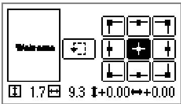
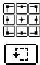
Moves the needle to the position of the selected needle start position.
Moves the frame to check the pattern position.
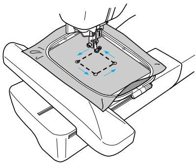
natural_image
Technical line drawing of a mechanical assembly with a tool inserted, showing internal components and motion arrows (no text or symbols)
CAUTION
● Never lower the needle when the embroidery frame is moving. The needle may break or bend.
- When you have revised the pattern, check the display of available embroidery frames and use an appropriate frame. If you use an embroidery frame not displayed as available for use, the presser foot may strike the frame and possibly cause injury.
4
Press

(Back key) to return to the original
screen.
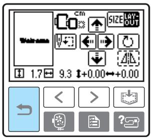

Memo
- When the machine is turned off, the layout returns to the original setting.
- You can also check the pattern size and distance from the center by pressing LAYOUT after starting embroidering.
Storing patterns
The embroidery patterns and the alphabet patterns you have customized can be stored in the machine's memory.
Since the stored patterns will not be erased when the machine is turned off, you can always recall them for embroidery. This is convenient for storing names and the like. You can store up to 12 patterns or 512 KB of data.
■ Storing a pattern

After selecting the pattern to be stored, press

(Memory key).
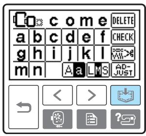
After the pattern is stored, the initial screen appears again.

Note
- Do not turn off the machine while the pattern is being stored, otherwise the pattern data may be lost.
■ Recalling a pattern.

Press | (Recall key).
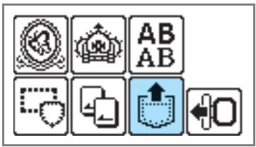
The stored patterns are displayed.

Select the pattern you wish to recall.
Switch screens using < (Previous page key) and > (Next page key).
②
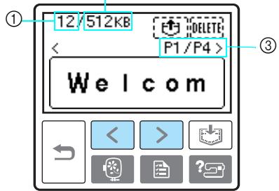
① Total amount of memory used
② Total amount of memory space
③ Number of the currently displayed page from the total number of pages
The selected pattern is shown in reverse highlighting.

Press
To delete the stored pattern, press DELETE.

The stored pattern is recalled and the embroidery screen appears. You can embroider the recalled pattern.
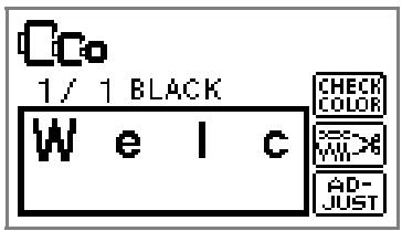

Note
● Characters saved from an embroidery card must have the embroidery card inserted in the machine in order to retrieve the memory saved from the embroidery card.
Adjusting the thread tension
If embroidery fails, it is difficult to undo the thread and the fabric may be damaged. Before embroidering, use a scrap of the same fabric to check the adjustment of the thread tension, etc.
To adjust the thread tension, press 📄 (Settings key).
![[ mm ] EMBROIDERY TENSION MAX EMBROIDERY SPEED ESO BSO SPM SPM < > ?](/content/2025/01/74636/images/89ab373d3abd4873e604144bf329599a741cacc14954fa234f005ef251fdf817.jpg)
Press ☐ to weaken the thread tension.
Press ☐ to tighten the thread tension.
■ Correct thread tension
The thread tension is correct when upper thread is just visible on back of the fabric.


① Right side
② Wrong side
■ Upper thread is too tight
The lower thread will be visible on the front of the fabric. In this instance, decrease the upper thread tension.


① Right side
② Wrong side
■ Upper thread is too loose
The upper thread has slack. In this instance, increase the upper thread tension.


① Right side
② Wrong side
Resewing
When the wrong upper thread color has been sewn, it can be resewn with the correct color.
1 Press ⏻ (Start/stop button) to stop the machine.
Press AD-JUST.
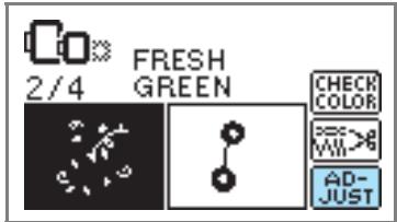
3 Press 4.
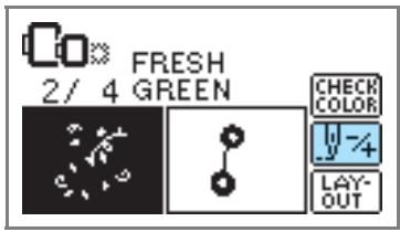
4 Press ☐ (Back one color) to return to the beginning of the mistaken color.
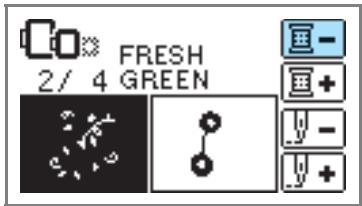
5 Set up the correct color for the upper thread.
6 Press ⏻ (Start/stop button) to continue the design.
Thread runs out partway through a design
When the upper thread or the bobbin thread runs out while embroidering, the machine stops. Move the needle back about 10 stitches and resume embroidering.
1 Set up the upper or bobbin thread.
2 Press AD-JUST.
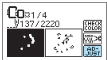
3 Press 4.
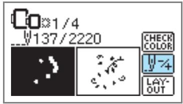
4 Press □ (Back one stitch) to move the needle back about 10 stitches.
Forward one stitch) increases the stitch number.
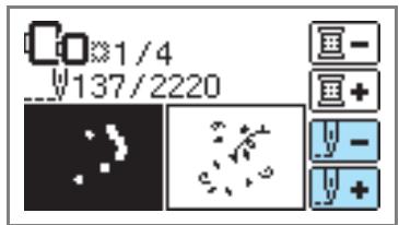
5 Restart the embroidery.
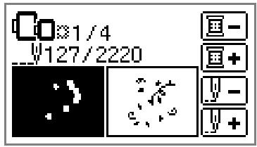
Stopping while embroidering
If the embroidery is stopped before it is complete, check the current needle count before turning off the machine.

Memo
- When the machine is turned off, the embroidery size and layout return to the original setting.
1 Press ⏻ (Start/stop button) to stop the machine.
2 Check the current needle count on the screen and make a note of it.

If the needle count is not displayed, press (Settings key), and then use ▶ to display the following screen.
![[NAME OF COLOR] [ ---- ]](/content/2025/01/74636/images/726003e78504cd061139c3a251b57209cc7969685bf3c4b667f72b0287fc2ea9.jpg)
![[NEEDLE COUNT] [ ---- ]](/content/2025/01/74636/images/05690664f58ae9ba473375b0d4b74547d311157f1f10eaa0bd5fd2647c4a7b92.jpg)
- Press (Back key) to return to the embroidery screen.
3 Press (Embroidery key).
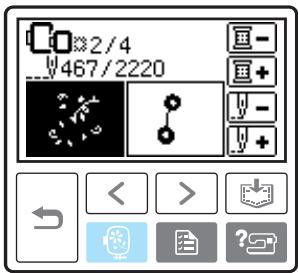
The confirmation message is displayed.
4 Press OK.
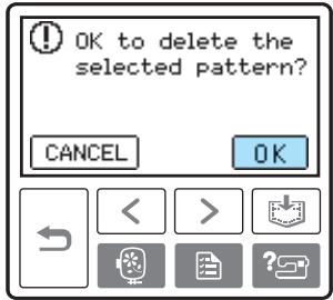
The selected pattern is deleted, and the screen for selecting the embroidery pattern type is displayed.
5 Turn off the machine.
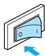
- Always remove the embroidery unit when you move the machine.
6 Turn on the machine and select the pattern.
7 Press AD-JUST.
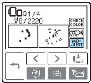

Press

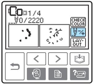

Press 📄+ (Forward one color) to move to the beginning of the color you want to embroider.
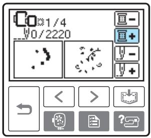

Press 📄 + (Forward one stitch) to increase the needle count.
If + is pressed continuously, it moves forward 1 9 30 stitches.
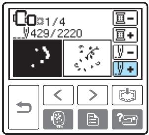
Move forward to about 10 stitches before the total number of stitches confirmed in 2.
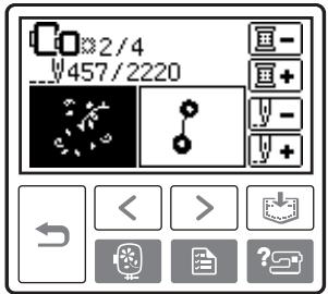

Restart the embroidery.
Bobbin Case Adjustment
The bobbin case installed in this machine can be adjusted, if necessary, to accommodate the bobbin tension for embroidering. The insertion below describes how to adjust the bobbin tension for embroidery use. Using a small slotted screwdriver, turn the slotted-head (b) screw to adjust the bobbin case tension.
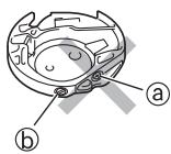
Ⓐ Do not turn a phillips screw (+).
⑥ Adjust with a screwdriver (small).
Correct tension
Upper thread slightly appears on the wrong side of fabric.


① Right side
② Wrong side
Bobbin thread is loose
Bobbin thread appears slightly on the right side of fabric.


① Right side
② Wrong side
If this occurs, turn the slotted-head screw (b) clockwise, being careful not to over-tighten the screw, approximately 30-45 degrees to increase bobbin tension.
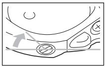
Bobbin thread is tight
Upper thread on the right side of fabric seems to be lifting/looping and bobbin thread is not seen on the wrong side of fabric.

① Right side
② Wrong side
If this occurs, turn the slotted-head screw (⑥) counterclockwise being careful not to over-loosen the screw, approximately 30-45 degrees to decrease bobbin tension.
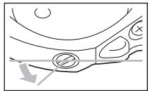

CAUTION
- When adjusting the bobbin case, be sure to remove the bobbin from the bobbin case.
● DO NOT adjust the position of the Phillips (ⓐ) screw on the bobbin case as this may result in damage to the bobbin case, rendering it unusable. - If the slotted-head screw (⑥) is difficult to turn, do not use force. Turning the screw too much or providing force in either (rotational) direction may cause damage to the bobbin case. Should damage occur, the bobbin case may not maintain proper tension.
3
APPENDIX
The various maintenance and troubleshooting procedures are described in this chapter.
Care and Maintenance ....70
Cleaning the machine surface 70
Cleaning the race....70
Attaching the Embroidery Foot....72
Attaching the embroidery Foot "Q"....72
Troubleshooting 74
Error messages ....78
Adjusting the LCD 81
Operation beep 81
Canceling the operation beep 82
Index 83
Care and Maintenance
Simple machine maintenance operations are described below.
Cleaning the machine surface
If the surface of the machine is dirty, lightly soak a cloth in neutral detergent, squeeze it out firmly, and then wipe the surface of the machine. After cleaning it once with a damp cloth, wipe it again with a dry cloth.

CAUTION
● Unplug the power supply cord before cleaning the machine, otherwise injuries or an electric shock may occur.
Cleaning the race
Embroidery performance will suffer if dust collects in the bobbin case, therefore, it should be cleaned periodically.
1 Turn off the machine.
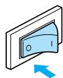
2 Unplug the power cord from the power supply jack on the right side of the machine.
CAUTION
● Unplug the power supply cord before cleaning the machine, otherwise injuries or an electric shock may occur.
3 Remove the embroidery unit.
4 Grasp both sides of the needle plate cover, and then slide it toward you.
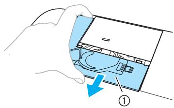
① Needle plate cover
The needle plate cover is removed.
5 Remove the bobbin case. Grasp the bobbin case, and then pull it out.
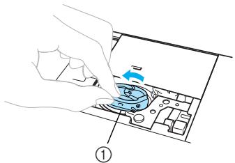
natural_image
Illustration of a hand inserting a component into a device (no text or symbols visible)① Bobbin case
6 Use the cleaning brush or a vacuum cleaner to remove any lint and dust from the race and bobbin thread sensor and their surrounding area.
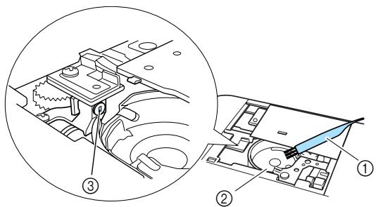
① Cleaning brush
② Race
③ Bobbin thread sensor
- Do not apply oil to the bobbin case.

Note
- If lint or dust collects on the bobbin thread sensor, the sensor may not operate correctly.
7 Insert the bobbin case so that the projection on the bobbin case aligns with the spring.
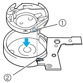
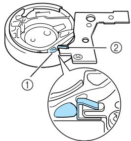
① Projection
② Spring
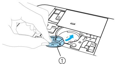
natural_image
Illustration of a hand pressing a button on a device panel with an arrow indicating motion (no text or symbols present)① Bobbin case
8 Insert the tabs on the needle plate cover into the needle plate, and then slide the cover back on.
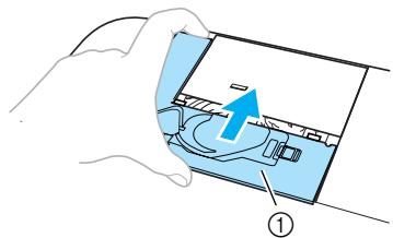
① Needle plate cover

CAUTION
● Never use a bobbin case that is scratched, otherwise the upper thread may become tangled, the needle may break or embroidering performance may suffer. For a new bobbin case (part code: XD1855-251), contact your nearest authorized service center.
- Be sure that the bobbin case is correctly installed, otherwise the needle may break.
Attaching the Embroidery Foot
This section describes how to attach the embroidery foot.
Attaching the embroidery Foot "Q"
Attach the embroidery foot "Q" when embroidering. Have the included embroidery foot "Q" and a screwdriver ready.
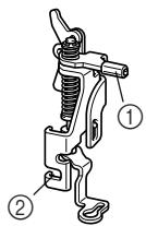
① Embroidery foot bar
② Caught by the presser foot holder screw

CAUTION
● Always use the embroidery foot "Q" when embroidering. If the wrong presser foot is used, the needle may hit the presser foot and break or bend.
1 Press ⏻ (Needle position button) once or twice to raise the needle.
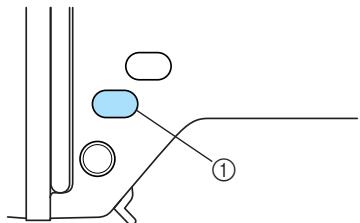
natural_image
Pure mechanical diagram showing a lever and pivot point without any text, numbers, or symbols① Needle position button
2 Turn off the machine.
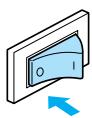
CAUTION
- Before attaching the embroidery foot, be sure to turn off the machine, otherwise injuries may occur if ⏻ (Start/stop button) is accidentally pressed and the machine starts embroidering.
3 Raise the presser foot lever.

① Presser foot lever
The embroidery foot is raised.
- At the time of purchase, the presser foot lever is up.
4 Hold the embroidery foot with your right hand, as shown.
Hold the embroidery foot with your index finger wrapped around the lever at the back of the foot.

① Lever
5 While pressing in the lever with your finger, fit the embroidery foot bar over the needle clamp screw to attach the embroidery foot to the presser foot bar.
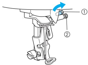
① Embroidery foot bar
② Needle clamp screw
6 Secure the embroidery foot with the presser foot holder screw.
Set the embroidery foot perpendicular.
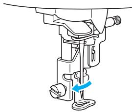
natural_image
Mechanical assembly diagram showing a sewing machine needle and base mount (no text or labels)7 Firmly tighten the presser foot holder screw. Turn the screwdriver toward the front.
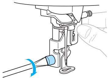
natural_image
Line drawing of a sewing machine needle being inserted into a socket (no text or symbols)
CAUTION
- Do not hit the needle with your finger or the embroidery foot when attaching it. The needle may break or cause injury.
- Be sure to tighten the screw with the included screwdriver. If the screw is loose, the needle may hit the embroidery foot and break or bend.
● Before embroidering, always turn the handwheel toward you (counterclockwise) slowly to make sure that the needle does not hit the embroidery foot. Otherwise, the needle may break or bend.
Troubleshooting
If the machine stops operating correctly, check the following possible problems before requesting service. If the problem persists, contact your retailer or the nearest authorized service center.
| Symptom | Probable Cause | Remedy | Reference |
| The machine does not operate. | The machine is not turned on. | Turn on the machine. | page 19 |
| The start/stop button was not pressed. | Press the start/stop button. | page 58 | |
| The presser foot lever is raised. | Lower the presser foot lever. | page 58 | |
| The embroidery unit is not attached on the machine. | Attach the embroidery unit. | page 15 | |
| The needle breaks. | The needle is incorrectly installed. | Correctly install the needle. | page 36 |
| The needle clamp screw is loose. | Use the screwdriver to firmly tighten the screw. | ||
| The needle is bent or blunt. | Replace the needle. | ||
| The upper thread tension is too tight. | Loosen the upper thread tension. | page 64 | |
| The spool is incorrectly installed. | Correctly install the spool. | page 30 | |
| The area around the hole in the needle plate is scratched, or has a burr on it. | Replace the needle plate. Contact your retailer or the nearest authorized service center. | - | |
| The area around the hole in the embroidery foot is scratched, or has a burr on it. | Replace the embroidery foot. Contact your retailer or the nearest authorized service center. | - | |
| The bobbin case is scratched, or has a burr on it. | Replace the bobbin case. Contact your retailer or the nearest authorized service center. | - | |
| A bobbin designed specifically for this machine is not used. | Incorrect bobbins will not work properly. Only use a bobbin designed specifically for this machine. | page 24 | |
| The upper thread breaks. | The upper thread was not threaded correctly (for example, the spool is not installed correctly, the spool cap is too big for the spool being used, or the thread has come out of the needle bar thread guide). | Correct the upper threading. | page 30 |
| There are knots or tangles in the thread. | Remove any knots or tangles. | - | |
| The upper thread tension is too tight. | Loosen the upper thread tension. | page 64 | |
| The upper thread breaks. | The thread is tangled, for example, in the bobbin case. | Remove the tangled thread. If the thread is tangled in the bobbin case, clean the race. | page 70 |
| The needle is bent or blunt. | Replace the needle. | page 35 | |
| The needle is incorrectly installed. | Correctly install the needle. | ||
| The area around the hole in the needle plate is scratched, or has a burr on it. | Replace the needle plate. Contact your retailer or the nearest authorized service center. | - | |
| The area around the hole in the embroidery foot is scratched, or has a burr on it. | Replace the embroidery foot. Contact your retailer or the nearest authorized service center. | - | |
| The bobbin case is scratched, or has a burr on it. | Replace the bobbin case. Contact your retailer or the nearest authorized service center. | - | |
| A bobbin designed specifically for this machine is not used. | Incorrect bobbins will not work properly. Only use a bobbin designed specifically for this machine. | page 24 | |
| Bobbin thread does not wind neatly on the bobbin. | The thread that was pulled out was not wound onto the bobbin correctly. | Wind the thread that was pulled off around the bobbin five or six times clockwise. | page 26 |
| The lower thread is tangled or breaks. | The bobbin thread is incorrectly installed. | Correctly install the bobbin thread. | page 28 |
| The bobbin is scratched or does not rotate smoothly, or has a burr on it. | Replace the bobbin. | - | |
| The thread is tangled. | Remove the tangled thread and clean the race. | page 70 | |
| A bobbin designed specifically for this machine is not used. | Incorrect bobbins will not work properly. Only use a bobbin designed specifically for this machine. | page 24 | |
| The thread tension is incorrect. | The upper thread was not threaded correctly. | Correct the upper threading. | page 30 |
| The bobbin thread is incorrectly installed. | Correctly install the bobbin thread. | page 28 | |
| The thread tension is incorrect. | Adjust the tension of the upper thread. | page 64 | |
| A bobbin designed specifically for this machine is not used. | Incorrect bobbins will not work properly. Only use a bobbin designed specifically for this machine. | page 24 | |
| Stitches are skipped. | The upper thread was not threaded correctly. | Correct the upper threading. | page 30 |
| The needle is bent or blunt. | Replace the needle. | page 35 | |
| The needle is incorrectly installed. | Correctly install the needle. | page 36 | |
| Dust has accumulated under the needle plate or in the bobbin case. | Remove the needle plate cover and clean the race. | page 70 | |
| A high-pitched noise is made while embroidering. | Dust has accumulated in the bobbin case. | Clean the race. | page 70 |
| The upper thread was not threaded correctly. | Correct the upper threading. | page 30 | |
| The bobbin case is scratched, or has a burr on it. | Replace the bobbin case. Contact your retailer or the nearest authorized service center. | - | |
| A bobbin designed specifically for this machine is not used. | Incorrect bobbins will not work properly. Only use a bobbin designed specifically for this machine. | page 24 | |
| The thread does not pass through the eye of the needle. | The needle has not been raised to the correct position. | Press the needle position button. | page 32 |
| The needle is incorrectly installed. | Correctly install the needle. | page 36 | |
| The stitch is not sewn correctly. | The thread tension is incorrect. | Adjust the tension of the upper thread. | page 64 |
| The thread is tangled, for example, in the bobbin case. | Remove the tangle thread. If the thread is tangled in the bobbin case, clean the race. | page 70 | |
| The lamps do not come on. | The lamps are damaged. | Contact your retailer or the nearest authorized service center. | - |
| The machine is not turned on. | Turn on the machine. | page 19 | |
| Nothing appears on the LCD. | The brightness of the LCD is either too light or too dark. | Adjust the brightness of the LCD. | page 81 |
| Machine does not operate when button is pressed. | An animation is displayed on the LCD. | Touch the LCD with your finger, and the animation will disappear. | page 20 |
| Embroidery unit does not move. | No pattern selected. | Select a pattern. | page 49 |
| The embroidery unit is not set up correctly. | Set up the embroidery unit correctly. | page 15 | |
| Embroidering continues although the bobbin thread ran out. | Dust has collected on the bobbin thread sensor. | Remove any dust from the bobbin thread sensor. | page 70 |
| Embroidery not neatly done. | The fabric is not fully stretched on the embroidery frame. The fabric is loose. | Stretch the fabric properly on the embroidery frame. | page 43 |
| No stabilizer material is attached. | Always use stabilizer material for embroidery with stretch fabrics, thin fabrics, fabrics with a loose weave and fabrics where stitches easily contract. | page 42 | |
| The thread is tangled and the bobbin case, etc., is plugged up. | Remove the tangled thread. When the bobbin case is plugged up, clean the race. | page 70 | |
| The thread tension is incorrect. | Adjust the tension of the upper thread. | page 64 | |
| Objects are placed near the carriage or embroidery frame. | If the embroidery unit carriage or embroidery frame bumps into objects, the pattern will be misaligned. Do not place objects within the range of embroidery frame motion. | page 16 | |
| Material coming out of the embroidery frame is causing problems. | Stretch the fabric on the frame once again so that the material coming out of the embroidery frame does not cause problems, rotate the pattern and embroider. | - | |
| When embroidering on a heavy fabric, the fabric is hanging off the table. | If embroidery is done with the fabric hanging off the table, the embroidery unit movement will be impaired. Support the fabric while embroidering. | - | |
| The fabric is catching. It is pinched. | Stop the machine and set up the fabric correctly. | - | |
| The carriage was moved while the embroidery frame was being removed or attached during embroidery. | If the carriage is moved during the process, the pattern may be misaligned. Be careful when removing or attaching the embroidery frame. | - |
Error messages
When erroneous operations are performed messages and advice on operation will be displayed on the LCD. Follow what is displayed. If you press CLOSE or do the operation correctly while the error message is displayed, the message disappears.
| Error Message | Probable Cause |
| 1 Can not recognize the data. The data may be corrupted. | There is a possibility that the data for the selected pattern is corrupted. |
| 1 Cannot sew on this screen. | The start/stop button was pressed at a screen other than the embroidery screen. |
| 1 Check and rethread the upper thread. | Upper thread broken. Upper thread not set up correctly. Upper thread has run out. CAUTION Be sure to rethread the machine. If you press ⏻ (Start/stop button) without rethreading the machine, the thread tension may be wrong or the needle may break and cause injury. |
| Deleting... | The machine is deleting a previously saved pattern. |
| 1 Insert an embroidery card. |  on the LCD was pressed when no card was inserted. on the LCD was pressed when no card was inserted. |
| 1 Lower the presser foot lever. | The start/stop button or thread cutter button was pressed while the embroidery foot was raised. |
| 1 Not enough available memory. Delete another pattern? | The memory is full and the pattern cannot be saved. |
| 1 OK to delete the selected pattern? | You pressed the back key or the embroidery key while a pattern was selected. |
| 1 Press the needle position button to raise the needle. | You tried to select an embroidery pattern or change the layout when the needle was down. The machine is turned on while the needle is lowered. |
| ⚠ Raise presser foot lever. | This message is displayed when the embroidery unit is trying to initialize while the embroidery foot is lowered. |
| ⚠ Return the bobbin winding shaft to left. | The needle position button or thread cutter button was pressed while the bobbin winder shaft is moved to the right. |
| Saving... | A pattern is being stored. |
| ⚠ Select a pattern. | The start/stop button was pressed when no pattern is selected. |
| ⚠ The bobbin thread is running out. | Bobbin thread has run out. Little bobbin thread remains. |
| ⚠ The carriage of the embroidery unit will move. | When the embroidery unit is attached, and then the machine is turned on. |
| ⚠ The pattern is too large for the embroidery frame. | You tried to set a number of characters that will not fit within the frame. |
| ⚠ The safety device has been activated. | The upper thread has become tangled around the bobbin case, and the needle is bent and hitting the needle plate, etc., so the machine stops (refer to page 74). |
| ⚠ This embroidery card can not be used on this machine. | A card that cannot be used with this machine has been inserted, and you tried to select a pattern from the card. |
| ⚠ This embroidery pattern can not be used on this machine. | An embroidery card incompatible with this machine was inserted and a pattern on the card was selected. |
| ⚠ This pattern cannot be used. | You try to retrieve a pattern downloaded as one for a different machine. |
| ⚠ Total size of the pattern is too large. Rotate the pattern. | The combined character pattern is too large for the embroidery frame. You can rotate the pattern 90 degrees and continue combining characters. |
| Turn off the machine, and attach the embroidery unit. | The machine was turned on before the embroidery unit was attached. |
| Winding bobbin thread... | The bobbin winder is winding the bobbin. |
Adjusting the LCD
If nothing appears on the LCD when the machine is turned on, the brightness of the LCD is either too light or too dark. In such a case, perform the following operation.
1 Turn off the machine.
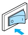
2 Turn on the machine while pressing any of the display panel buttons.
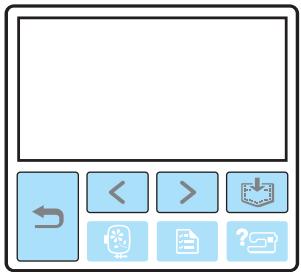
3 Press - or +.
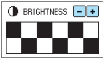
4 Turn off the machine, then turn it on again.
Operation beep
Each time a key is pressed you will hear one beep. If an incorrect operation is performed you will hear two or four beeps.
■ If a key is pressed (correct operation)
One beep sounds.
■ If an incorrect operation is performed
Two or four beeps sound.
■ If the machine locks up, for example, because the thread is tangled
The machine beeps for four seconds and the machine automatically stops.
Be sure to check for the cause of the error, and correct it before continuing to embroider.
Canceling the operation beep
When the machine is purchased, it is set to beep each time an operation panel key is pressed. This setting can be changed so that the machine does not beep.
1 Turn on the machine.

The LCD comes on.
2 Press 📄 (Settings key) on the operation panel.

The settings screen appears.
3 Press ▶ (Next page key) three times.
4 Press OFF for the buzzer.
![BUZZER ON OFF OPENING ON OFF [ ENGLISH ]](/content/2025/01/74636/images/015f7ad52070e953c7f97930fcaa1b0e30b08aa5ec225a41794ff71e5d08dc2f.jpg)
The screen for changing the beep setting appears.
5 Press (Back key).
![BUZZER ON OFF OPENING ON OFF [ ENGLISH ]](/content/2025/01/74636/images/1a6e583d251a8aabccc4072aab3c0f99668cec8701c3fcf4c20e63dbe2f5c685.jpg)
The initial screen appears again.
Index
A
accessories 6
air vent 9
appliqué 59
B
back key 11
beep 81,82
bobbin 6
bobbin case 9
bobbin case removal 70
bobbin cover 9
bobbin installation 28
bobbin winder 8
bobbin winding 24
bobbin winding thread guide 8
Brother poly #90 bobbin thread 7
buzzer 82
C
characters 52
cleaning 70
cleaning brush 6
D
dust cover 6
E
embroidery card 7,55
embroidery card slot 9
Embroidery foot "Q" 6,9
embroidery foot attachment 72
embroidery frame 43
embroidery frame attachment 47
embroidery frame removal 48
embroidery key 11
embroidery pattern 53
embroidery pattern selection 49
embroidery pattern types 49
embroidery set 6,7
embroidery sheets 45
embroidery unit 8
embroidery unit attachment 15
embroidery unit connector slot 8
embroidery unit removal 16
error messages 78
F
frame pattern 54
H
handle 9
handwheel 9
help key 11,23
|
included accessories 6
L
layout adjustment 61
LCD 11
LCD button 51
LCD operation 20,50
M
machine settings 21
main power switch 9,19
maintenance 70
manual needle threading 34
memory key 11,63
N
needle bar thread guide 9
needle plate 9
needle plate cover 9
needle position button 10
needle replacement 36
needle set 6
needle threader 32
needle threader lever 8
needle threading 32
next page key 11
O
operation beep 81, 82
operation buttons 8,10
operation keys 11,50
operation panel 8,11
optional accessories 7
P
pattern type selection screen 20
power supply 18
power supply jack 9
preparations for embroidering 40
presser foot lever 8
previous page key 11
Q
quick reference guide 6
R
race 70
recalling a pattern 63
release button 17
resewing 65
S
scissors 6
screwdriver 6
seam ripper 6
settings key 11,22
spool cap 6
spool net 6,25
spool of thread 30
spool pin 8
stabilizer material 7,42
start/stop button 10
storing pattern 63
T
thread cutter 8
thread cutter button 10
thread guide cover 8
thread guide disk 9
thread guide plate 8
thread take-up lever check window 8
thread tension adjustment 64
top cover 8
touch panel 11
troubleshooting 74
turning machine on/off 19
U
upper threading 30
- Operation Manual
- IMPORTANT SAFETY INSTRUCTIONS
- DANGER - To reduce the risk of electric shock
- WARNING - To reduce the risk of burns, fire, electric shock, or injury to persons.
- This machine is not a toy:
- For a longer service life:
- For repair or adjustment:
- SAVE THESE INSTRUCTIONS This machine is intended for household use.
- FOR USERS IN THE UK, EIRE, MALTA AND CYPRUS ONLY
- IMPORTANT
- FOR USERS IN AC INPUT 220-240V COUNTRIES AND MEXICO
- Contents
- GETTING READY
- EMBROIDERY
- Embroidering....56
- Editing and Saving Patterns ....61
- Bobbin Case Adjustment 68
- APPENDIX 69
- Care and Maintenance ....70
- Attaching the Embroidery Foot....72
- Troubleshooting 74
- Index 83
- Introduction
- Machine Features
- Accessories
- Included accessories
- Optional accessories
- Memo
- Names of Machine Parts and Their Functions
- Front view
- Needle and embroidery foot section
- Right-side/rear view
- Operation buttons
- ① Start/stop button
- ② Needle position button
- ③ Thread cutter button ✗
- CAUTION
- Note
- Operation panel
- 1
- Embroidery Step by Step
- Attaching the Embroidery Unit
- Embroidery unit precautions
- Turn off the machine.
- Slide the embroidery unit onto the machine arm.
- Turn on the machine.
- Be sure that no objects or hands are near the embroidery unit and press OK.
- Removing the embroidery unit
- Remove the embroidery frame.
- Press 🔍, and then press OK.
- Turn off the machine.
- Turning the Machine On/Off
- Power supply precautions
- WARNING
- Turning on the machine
- Turning off the machine
- LCD (Liquid Crystal Display) Operation
- Viewing the LCD
- ■ Pattern type selection screen
- Changing the machine settings
- Turn on the machine.
- Press (Settings key) on the operation panel.
- Press the item to be set.
- Checking machine operating procedures
- Press ? (Help key) on the operation panel.
- Press the item to be displayed.
- Press > (Next page key) to switch to the next page.
- ☐ Example: Upper threading
- After you finish checking, press key) two times. (Back
- Winding/Installing the Bobbin
- Bobbin precautions
- Winding the bobbin
- Place the spool of thread for the bobbin onto the spool pin.
- Slide the spool cap onto the spool pin.
- Installing the bobbin
- Slide the bobbin cover latch to the right.
- Remove the bobbin cover.
- Hold the bobbin with your right hand and hold the end of the thread with your left.
- Insert the bobbin into the bobbin case so that the thread unrolls to the left.
- Lightly hold down the bobbin with your right hand, and then guide the thread as shown with your left hand.
- Reattach the bobbin cover.
- Upper Threading
- About the spool of thread
- Threading the upper thread
- Open the top cover.
- Remove the spool cap that is inserted onto the spool pin.
- Place the spool of thread onto the spool pin.
- While holding the thread lightly with your right hand, pull the thread with your left hand, and then pass the thread behind the thread guide cover and to the front.
- Pass the thread under the thread guide plate, and then pull it up.
- Threading the needle
- Cut the thread with the cutter on the left side of the machine.
- Lower the presser foot lever to lower the embroidery foot.
- Lower the needle threader lever on the left side of the machine until it clicks, and then slowly return the lever to its original position.
- Threading the needle manually (without using the needle threader)
- Replacing the Needle
- Needle precautions
- Checking the needle
- 2
- Embroidering Neatly
- What to prepare
- Fabric
- ■ Stabilizer material
- ■ Embroidery thread
- Needle
- ■ Other
- Preparing the Fabric
- Attaching a stabilizer material to the fabric
- Setting the fabric in the embroidery frame
- ■ Embroidery frame (large)
- ■ Embroidery frame (medium)[option]
- ■ Embroidery frame (small)[option]
- ■ Embroidery frame (extra large (multi-position)) [option]
- Loosen the embroidery frame adjustment screw and remove the inner and outer frames, placing the outer frame on a flat surface.
- Place the fabric with the stabilizer material on top of the outer frame.
- Press the inner frame in from the top of the fabric.
- Tighten the adjustment screw by hand just enough to secure the fabric.
- Gently remove the fabric from the frame without loosening the adjustment screw.
- Press the inner frame in from the top of the fabric again, lining up △ on the inner frame and ▽ on outer frame.
- Tighten the adjustment screw while removing any slack in the fabric by hand. The goal is to have a drum-like sound when the stretched fabric is struck lightly.
- ■ Using embroidery sheets
- ■ Embroidery on fabrics that cannot be stretched on an embroidery frame
- Attaching the Embroidery Frame
- Removing the embroidery frame
- Raise the presser foot lever.
- While pushing the lever of the embroidery frame holder to the left, lift the embroidery frame up to remove it.
- Pass the embroidery frame under the embroidery foot while raising the presser foot lever even further.
- Selecting Embroidery Patterns
- Copyright information
- Embroidery pattern types
- ■ Embroidery patterns (Embroidery patterns/Additional embroidery patterns)
- ■ Alphabet patterns
- Frame patterns
- ■ Embroidery card (sold separately)
- ■ Patterns stored in the machine's memory
- ■ Operation keys
- 123: Select from the following thread color number sets
- DISPLAY UNIT
- EMBROIDERY TENSION
- MAX EMBROIDERY SPEED (SPM)
- LCD button
- Selecting characters
- Select the alphabet patterns.
- Select the character style.
- Select the characters. If a wrong character was selected, press DELETE.
- Example: Welcome
- Selecting an embroidery pattern
- Select the type of the embroidery pattern.
- Select the pattern.
- Selecting a frame pattern
- Press the frame pattern.
- Select the frame shape.
- Select the stitch.
- Using an embroidery card (sold separately)
- Insert the embroidery card in the embroidery card slot on the right side of the machine.
- Press the embroidery card on the screen.
- Select a pattern. The operation is the same as in “Selecting Embroidery Patterns” (page 49).
- Embroidering
- Embroidering attractive finishes
- Embroidering a pattern
- Prepare embroidery thread of the color shown on the screen.
- Set the embroidery thread, thread the needle, then pass the end of the thread through the embroidery foot hole.
- Lower the presser foot lever.
- Press ⏻ (Start/stop button).
- After progressing 5-6 stitches, press ⏻ (Start/stop button) to stop the machine.
- Use scissors to cut the thread at the beginning of the stitching.
- Press ⏻ (Start/stop button) again.
- Press ⬆ (Thread cutter button) once.
- Set up embroidery thread for the next color, and repeat steps 1 through 8.
- Cut the excess thread.
- Appliquéing
- Select an appliqué pattern.
- When "APPLIQUE MATERIAL" is displayed on the screen, apply iron-on stabilizer to the back of the appliqué piece fabric, and stretch it on the embroidery frame.
- Lower the presser foot lever, and press (Start/stop button).
- Remove the fabric from the embroidery frame, and cut it out along the cut-out line.
- Stretch the base fabric on the embroidery frame.
- Set up the thread for appliquéing.
- Lower the presser foot lever, and press (Start/stop button).
- Apply a thin layer of fabric glue or spray adhesive to the back of the appliqué piece, and attach it in the appliqué position.
- Editing and Saving Patterns
- Adjusting the layout
- After selecting the embroidery pattern, press AD-JUST.
- Press LAY-OUT.
- Check and adjust the layout.
- Embroidery frame size
- Size key
- Change position keys
- Layout key
- Rotation key
- Horizontal mirror image key
- Starting point key
- 4
- Press
- Storing patterns
- ■ Storing a pattern
- ■ Recalling a pattern.
- Select the pattern you wish to recall.
- Adjusting the thread tension
- ■ Correct thread tension
- ■ Upper thread is too tight
- ■ Upper thread is too loose
- Resewing
- Thread runs out partway through a design
- Stopping while embroidering
- Bobbin Case Adjustment
- Correct tension
- Bobbin thread is loose
- Bobbin thread is tight
- 3
- APPENDIX
- Care and Maintenance
- Cleaning the machine surface
- Cleaning the race
- Attaching the Embroidery Foot
- Attaching the embroidery Foot "Q"
- Secure the embroidery foot with the presser foot holder screw.
- Firmly tighten the presser foot holder screw. Turn the screwdriver toward the front.
- Troubleshooting
- Error messages
- Adjusting the LCD
- Turn on the machine while pressing any of the display panel buttons.
- Press - or +.
- Turn off the machine, then turn it on again.
- Operation beep
- Canceling the operation beep
- Press 📄 (Settings key) on the operation panel.
- Press ▶ (Next page key) three times.
- Press OFF for the buzzer.
- Press (Back key).
- Index
- A
- B
- C
- D
- E
- F
- H
- |
- L
- M
- N
- O
- P
- Q
- R
- S
- T
- U
Marque : BROTHER
Modèle : INNOV-IS 700E
Catégorie : Machine à coudre à broder