Hydro Solo-E CRIE 5-7 - équipements de mesure Grundfos - Notice d'utilisation et mode d'emploi gratuit
Retrouvez gratuitement la notice de l'appareil Hydro Solo-E CRIE 5-7 Grundfos au format PDF.

| Marque | Grundfos |
| Modèle | Hydro Solo-E CRIE 5-7 |
| Catégorie | Équipements de mesure |
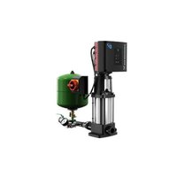
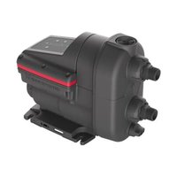
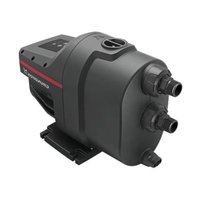
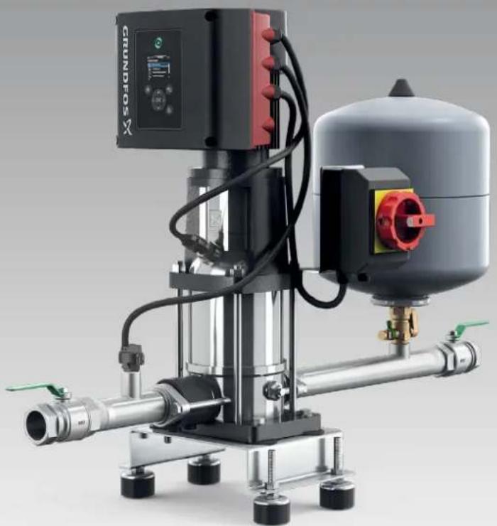
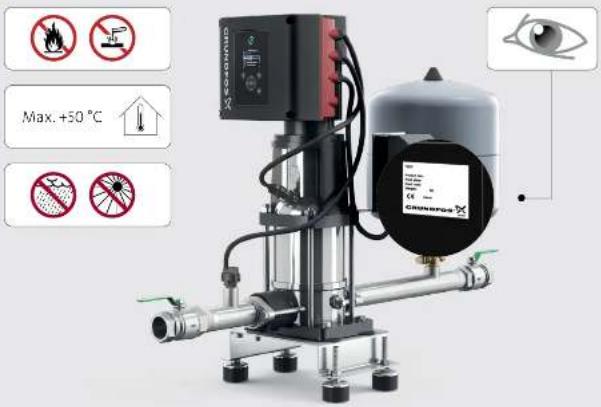
| Type de produit | Pompe de surpression avec contrôle électronique |
| Fonctions principales | Régulation de pression, protection contre la marche à sec, démarrage/arrêt automatique |
| Pression de service max. | 10 bar |
| Température du liquide max. | 50 °C |
| Alimentation électrique | 400 V triphasé (estimation) |
| Puissance moteur | 5 kW (estimation) |
| Dimensions (L × l × h) | 800 × 400 × 600 mm (estimation) |
| Poids | 40 kg (estimation) |
| Indice de protection | IP54 |
| Affichage | Écran LCD avec contrôleur Grundfos |
| Entretien | Nettoyage régulier du filtre, vérification des joints |
| Sécurité | Protection contre les surcharges, marche à sec, et défauts électriques |
| Pièces détachées | Disponibles via le réseau Grundfos |
| Réparabilité | Indice de réparabilité estimé : 8/10 (conception modulaire) |
FOIRE AUX QUESTIONS - Hydro Solo-E CRIE 5-7 Grundfos
Questions des utilisateurs sur Hydro Solo-E CRIE 5-7 Grundfos
0 question sur cet appareil. Repondez a celles que vous connaissez ou posez la votre.
Poser une nouvelle question sur cet appareil
Téléchargez la notice de votre équipements de mesure au format PDF gratuitement ! Retrouvez votre notice Hydro Solo-E CRIE 5-7 - Grundfos et reprennez votre appareil électronique en main. Sur cette page sont publiés tous les documents nécessaires à l'utilisation de votre appareil Hydro Solo-E CRIE 5-7 de la marque Grundfos.
MODE D'EMPLOI Hydro Solo-E CRIE 5-7 Grundfos
GRUNDFOS INSTRUCTIONS
natural_image
Industrial pump system with control panel and cylindrical tank (no visible text or symbols)HYDRO SOLO-E
OPTIMUM
be
think
innovate
GRUNDFOS

i
text_image
Max. +50 °C Converancei
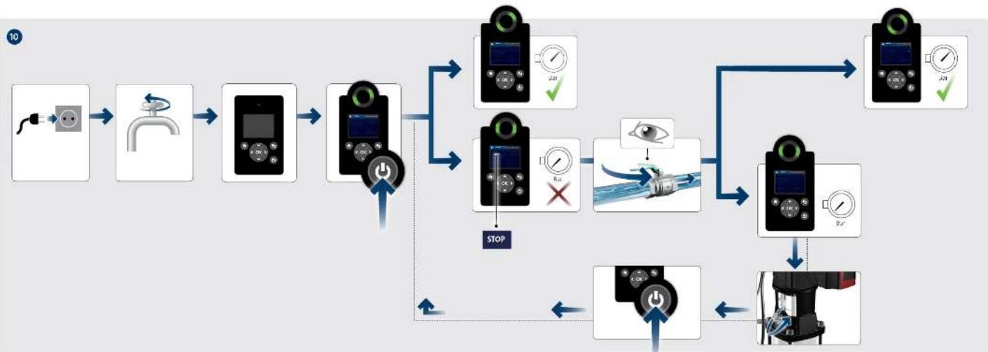
flowchart
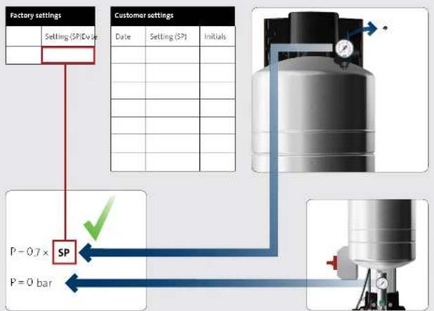
graph TD
    A["Factory settings"] --> B["Setting (SP) value"]
    B --> C["Customer settings"]
    C --> D["Date"]
    C --> E["Setting (SP)"]
    C --> F["Initials"]
    G["P = 0 bar"] --> H["SP"]
    H --> I["P = 0.7 ×"]
    I --> J["Valve Diagram"]
    J --> K["Arrow to Factory setting"]

natural_image
Four gray square icons with white circular and electrical symbols: info, upload arrow, power plug, and hand (no text or labels)i
text_image
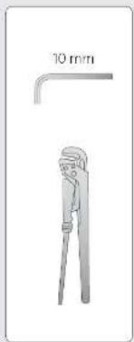
10 mm1
natural_image
Industrial machine setup with coiled cable and pressure gauge, showing internal components and wiring (no text or symbols visible)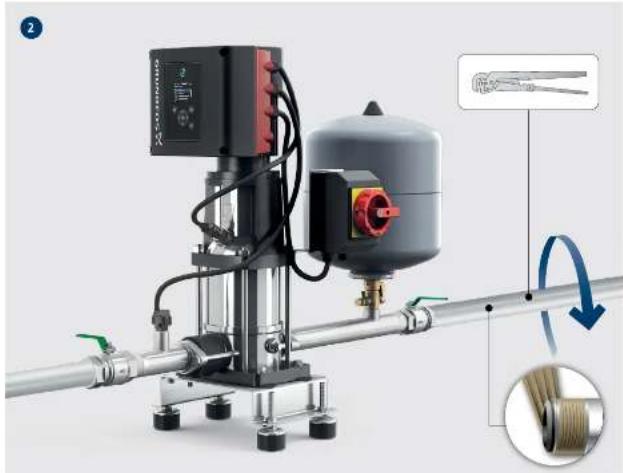
natural_image
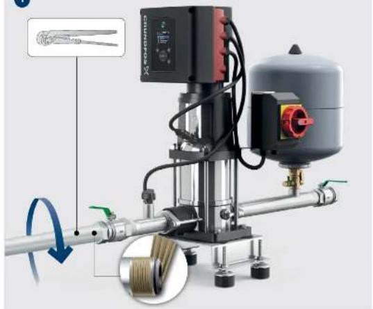
Industrial piping system with control panel and motor, showing mechanical components and a close-up of a cable being inserted (no text or symbols visible)
natural_image
Four gray square icons representing information, power, plug, and cursor (no text or symbols)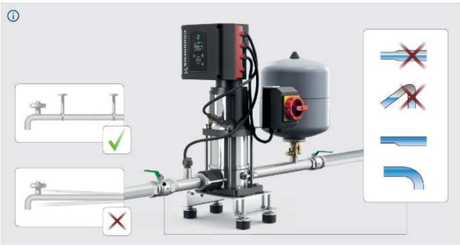
text_image
Technical diagram of a pressure pump system with labeled components and safety check indicators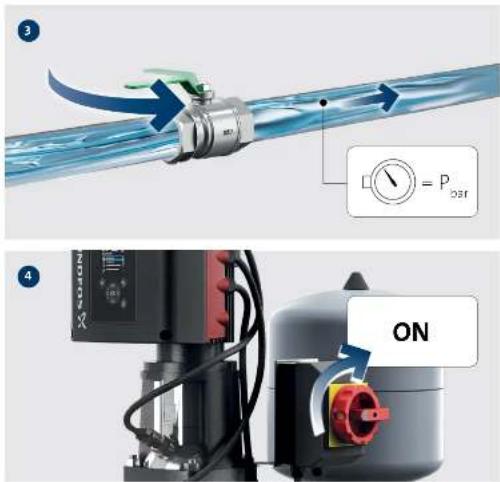
text_image
3 P = P Gear 4 ON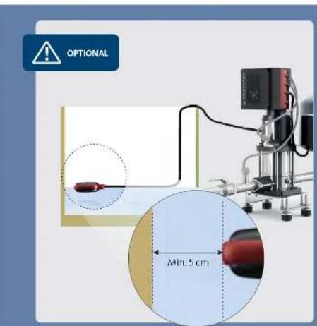
text_image
OPTIONAL Min. 5 cm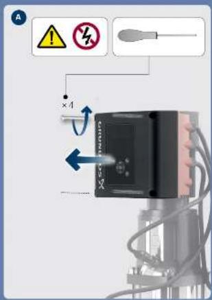
text_image
Diagram showing electrical hazard symbols and a device with labeled components and directional arrows indicating current flow or voltage.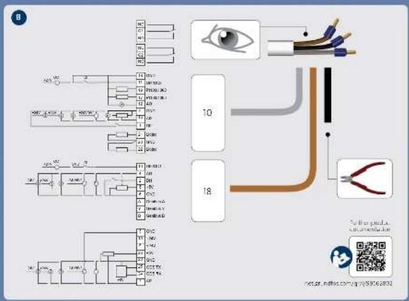
flowchart
graph TD
    A["ICs"] --> B["Switch"]
    B --> C["Switch"]
    C --> D["Switch"]
    D --> E["Switch"]
    E --> F["Switch"]
    F --> G["Switch"]
    G --> H["Switch"]
    H --> I["Switch"]
    I --> J["Switch"]
    J --> K["Switch"]
    K --> L["Switch"]
    L --> M["Switch"]
    M --> N["Switch"]
    N --> O["Switch"]
    O --> P["Switch"]
    P --> Q["Switch"]
    Q --> R["Switch"]
    R --> S["Switch"]
    S --> T["Switch"]
    T --> U["Switch"]
    U --> V["Switch"]
    V --> W["Switch"]
    W --> X["Switch"]
    X --> Y["Switch"]
    Y --> Z["Switch"]
    Z --> AA["Switch"]
    AA --> AB["Switch"]
    AB --> AC["Switch"]
    AC --> AD["Switch"]
    AD --> AE["Switch"]
    AE --> AF["Switch"]
    AF --> AG["Switch"]
    AG --> AH["Switch"]
    AH --> AI["Switch"]
    AI --> AJ["Switch"]
    AJ --> AK["Switch"]
    AK --> AL["Switch"]
    AL --> AM["Switch"]
    AM --> AN["Switch"]
    AN --> AO["Switch"]
    AO --> AP["Switch"]
    AP --> AQ["Switch"]
    AQ --> AR["Switch"]
    AR --> AS["Switch"]
    AS --> AT["Switch"]
    AT --> AU["Switch"]
    AU --> AV["Switch"]
    AV --> AW["Switch"]
    AW --> AX["Switch"]
    AX --> AY["Switch"]
flowchart
graph TD
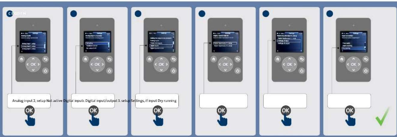
A["Analog input 2, setup Not active Digital inputs Digital input/output 3. setup Settings, if input Dry running"] --> B["OK"]
C["Analog input 1, setup Analog input 2, setup Analog input 3"] --> D["OK"]
E["Digital input 1, setup Digital input/Output 3"] --> F["OK"]
G["Digital input 2, setup Digital input/Output 3"] --> H["OK"]
I["Digital input 3, setup Digital input/Output 3"] --> J["OK"]
K["Digital input 4, setup Digital input/Output 3"] --> L["OK"]
M["Digital input 5, setup Digital input/Output 3"] --> N["OK"]
O["Digital input 6, setup Digital input/Output 3"] --> P["OK"]
Q["Digital input 7, setup Digital input/Output 3"] --> R["OK"]
S["Digital input 8, setup Digital input/Output 3"] --> T["OK"]
U["Digital input 9, setup Digital input/Output 3"] --> V["OK"]
W["Digital input 10, setup Digital input/Output 3"] --> X["OK"]
Y["Digital input 11, setup Digital input/Output 3"] --> Z["OK"]
AA["Digital input 12, setup Digital input/Output 3"] --> AB["OK"]
AC["Digital input 13, setup Digital input/Output 3"] --> AD["OK"]
AE["Digital input 14, setup Digital input/Output 3"] --> AF["OK"]
AG["Digital input 15, setup Digital input/Output 3"] --> AH["OK"]
AI["Digital input 16, setup Digital input/Output 3"] --> AJ["OK"]
AK["Digital input 17, setup Digital input/Output 3"] --> AL["OK"]
AM["Digital input 18, setup Digital input/Output 3"] --> AN["OK"]
AO["Digital input 19, setup Digital input/Output 3"] --> AP["OK"]
AQ["Digital input 20, setup Digital input/Output 3"] --> AR["OK"]
AS["Digital input 21, setup Digital input/Output 3"] --> AT["OK"]
AU["Digital input 22, setup Digital input/Output 3"] --> AV["OK"]
AW["Digital input 23, setup Digital input/Output 3"] --> AX["OK"]
AY["Analog input 2"] --> AZ["OK"]
BA["Analog input 1"] --> BB["OK"]

natural_image
Four gray vertical bars with white circular icons: info, gear, power plug, and fingerprint (no text or symbols)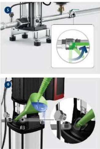
natural_image
Technical illustration of a mechanical device with green tubing and a magnified inset showing a rotating component (no text or symbols)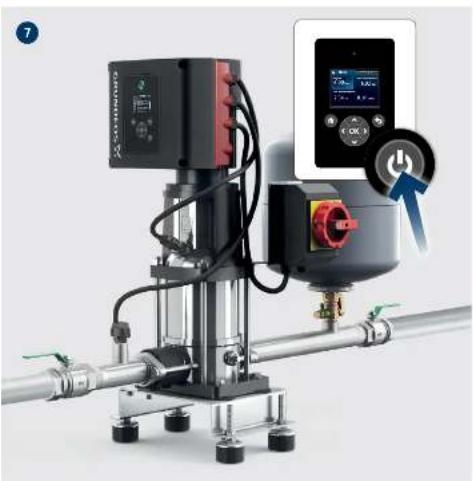
natural_image
Industrial pump system with digital display and control panel (no visible text or symbols)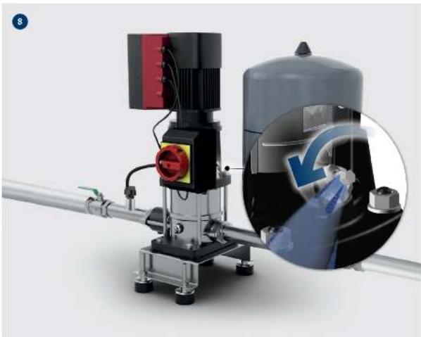
natural_image
Industrial piping and pressure vessel with a magnified inset showing a hand holding a valve (no visible text or symbols)1213

natural_image
Four gray square icons with white symbols: info, weather, plug, and hand (no text or numbers)i
text_image
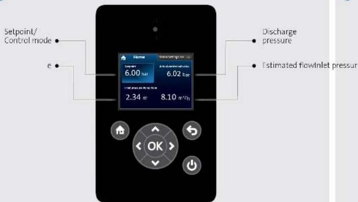
Setpoint/ Control mode e Discharge pressure Estimated flowinlet pressure 6.00 bar 6.02 bar 2.34 m 8.10 mV/h OKi
text_image
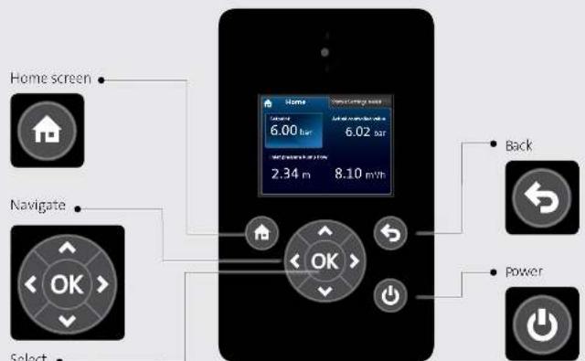
Home screen Navigate Select Back Power1415
flowchart
graph TD
    A["Initial Discharge"] --> B["Respiratory Valve"]
    B --> C["Medical Device"]
    C --> D{Control Check}
    D -->|Yes| E["Monitor 1"]
    D -->|No| F["Monitor 2"]
    E --> G{Check Point}
    F --> H{Check Point?}
    G --> I["End"]
    H --> J["End"]
    style A fill:#f9f,stroke:#333
    style I fill:#ccf,stroke:#333

natural_image
Vertical arrangement of four gray icons with white symbols: info, gear, power plug, and hand icon (no text or labels)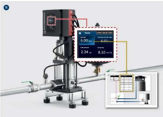
text_image
Home Fuel Rate, Speed Sension: 6.00 gm Fuel Rate, Speed, L/min 6.02 m Fuel Pressure: 2.34 m Fuel Flow: 8.10 m³/h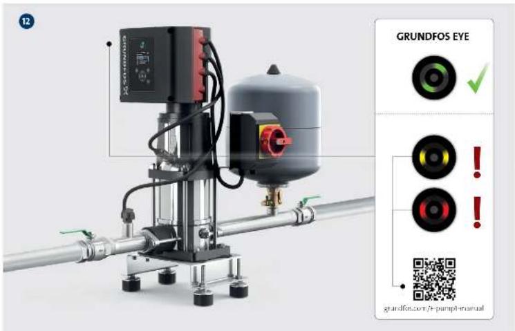
text_image
GRUNDFOS EYE GRUNDFOS EYE GRUNDFOS EYE GRUNDFOS EYE GRUNDFOS EYE GRUNDFOS EYE GRUNDFOS EYE GRUNDFOS EYE GRUNDFOS EYE GRUNDFOS EYE GRUNDFOS EYE GRUNDFOS EYE GRUNDFOS EYE GRUNDFOS EYE GRUNDFOS EYE GRUNDFOCS/PT-pumpf-manual1819

natural_image
Vertical arrangement of four gray icons with white symbols: info, power plug, grid, and hand icon (no text or labels)
natural_image
Industrial piping system with digital display and control panel (no readable text or symbols)
text_image
Further product documentation grundfos.com/ -pumpit-manual product-selection. grundfos.com2021

text_image
i2223
text_image
i
natural_image
Blank lined paper with no text, numbers, or symbolsbe think innovate
99838821 12.2021
ECM: 1327040
GRUNDFOS Holding A/S
Poul Due Jensens Vej 7
DK-8850 Bjerringbro
Tel: +45 87 50 14 00
www.grundfos.com
Trademarks displayed in this material, including but not limited to Grundfos, the Grundfos logo and "be Think innovale" are registered trademarks owned by The Grundfos Group. All rights reserved.
© 2021 Grundfos Holding A/S, all rights reserved.
GRUNDFOS