MODE D'EMPLOI KD 2100 KENWOOD
SERVICE MANUAL
KD-2100
FULL-AUTOMATIC TURNTABLE
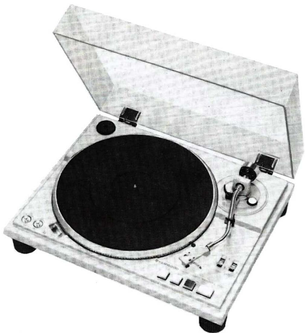
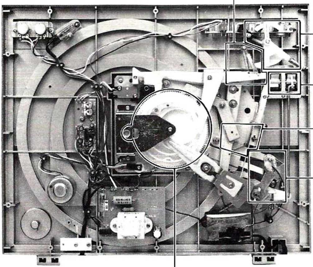
EXTERNAL AND INTERNAL VIEWS
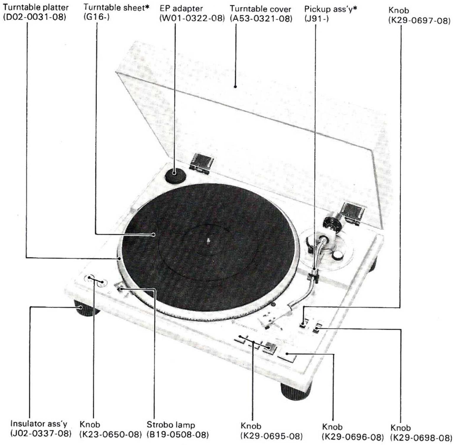
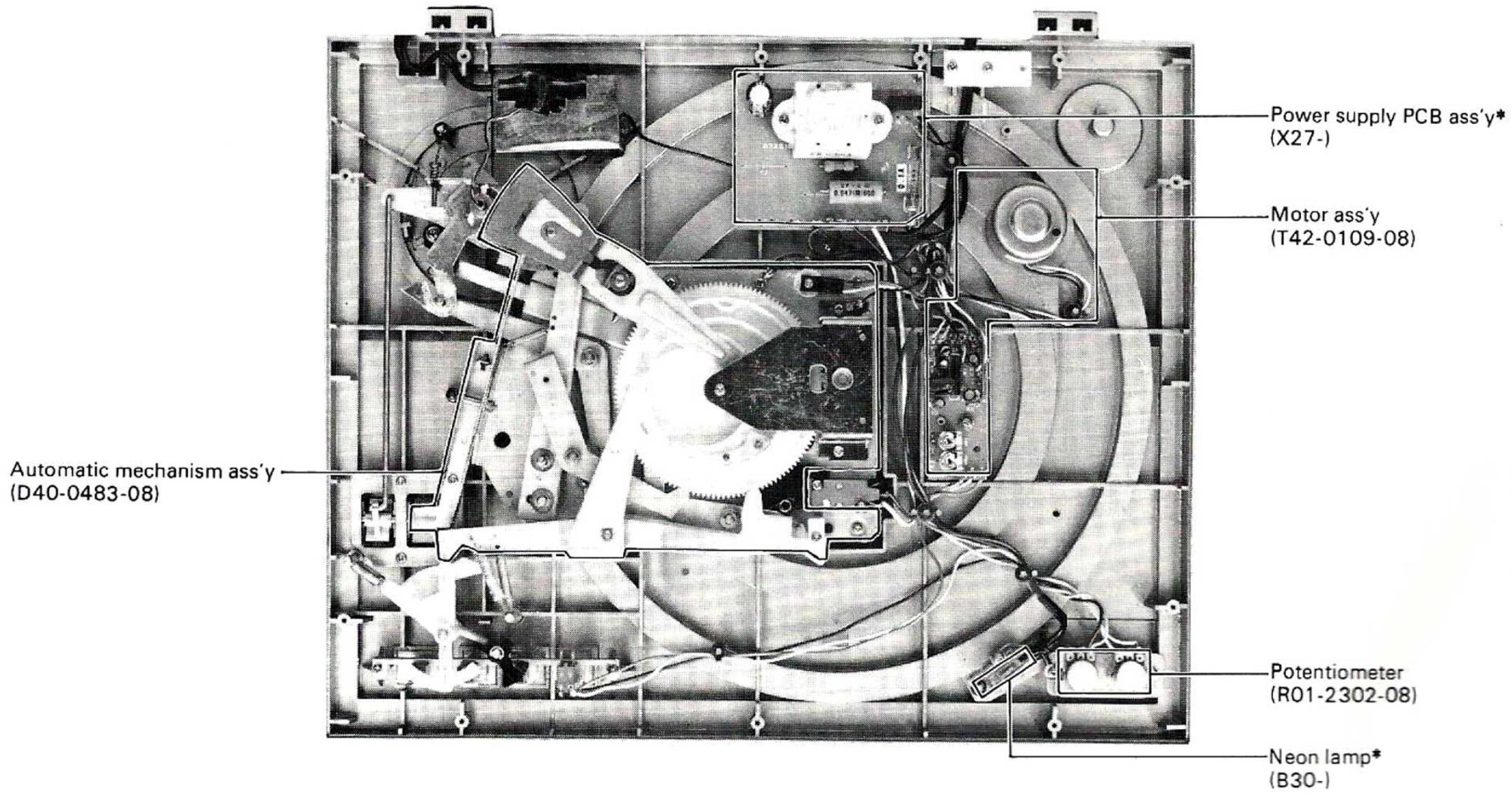
* Refer to Parts List.
OPERATION OF MECHANISM
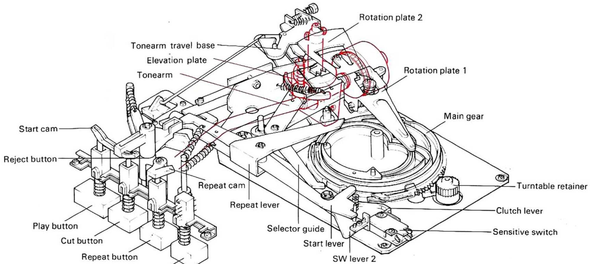
Fig.1 STOP Mode
The KD-2100 employs an innovative full-automatic mechanism which is completely new. With this mechanism, the energy of turntable rotation is used to operate the PLAY, CUT and REPEAT and raise or lower the tonearm smoothly. Du
ring record playback, the full-automatic mechanism is completely disengaged from the platter, ensuring the stable rotation.
1. PLAY Mode
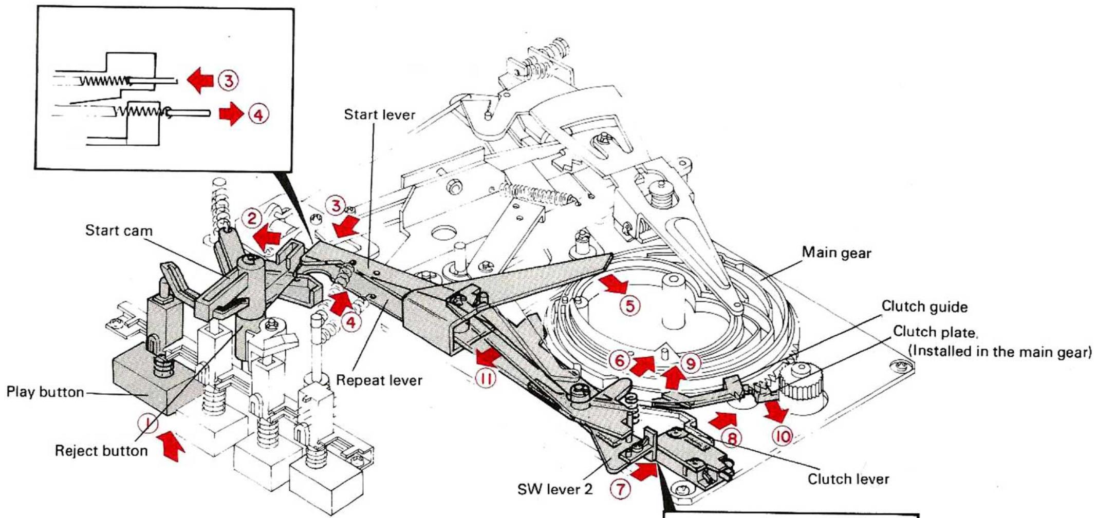
Fig.2 When PLAY Button is Pressed
Pressing the play button ① rotates the start cam in direction ② about 20^ . The start lever is unlocked from the start cam and is drawn by the spring in direction ③. The other end of the start lever shifts in direction ⑥, thus the SW lever 2 is shifted in direction ⑦ to turn ON the microswitch to start the motor. The start lever shifts the clutch lever in direction ⑧ and the clutch guide and clutch plate move in directions ⑨
and 10 respectively. The clutch plate is engaged with the turntable retainer gear and the main gear starts rotating (Fig. 2). The reject lever coupled with the start cam starts rotating in direction 2 and the repeat lever moves in direction 4 and 5 (Fig. 2).
OPERATION OF MECHANISM
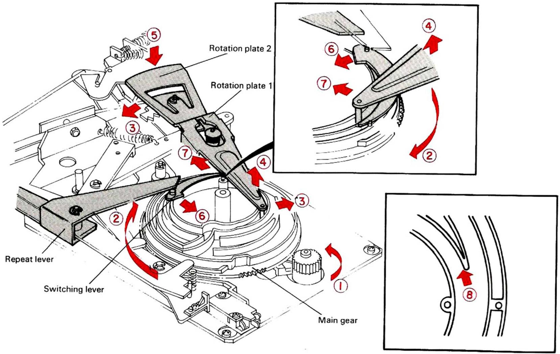
Fig. 3 Rotation of Main Gear
When the turntable is rotating in direction ①, the main gear rotates in direction ②, resulting the rotation plate 1 to move in direction ③. As the depth of the main gear groove becomes shallower, the rotation plate rises in direction ④ and the rotation plate 2 which is fixed in the other end of the rotation plate 1 is lowered in direction ⑤. As a result of this motion, the tonearm rises (Fig. 3).
When the main gear rotates further, the switching lever is shifted in direction 6 by the repeat lever and the rotation plate 1 enters the inner groove of the main gear (in directions 7 and 8 (Fig. 3).
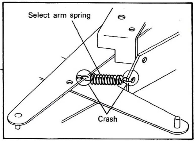
When rotation plate 1 enters the inner groove of the main gear, the end of the selector guide comes to the part where the radius of the main gear becomes smaller, letting the end move inward (in direction ②). The other end of the selector guide shifts in direction ③ and the selector arm is drawn by the spring in direction ④. The record size selector which is set by the selector knob on the cabinet comes into contact with the end of the selector arm to determine the position where the tonearm is to be lowered. (Fig. 4-1.)
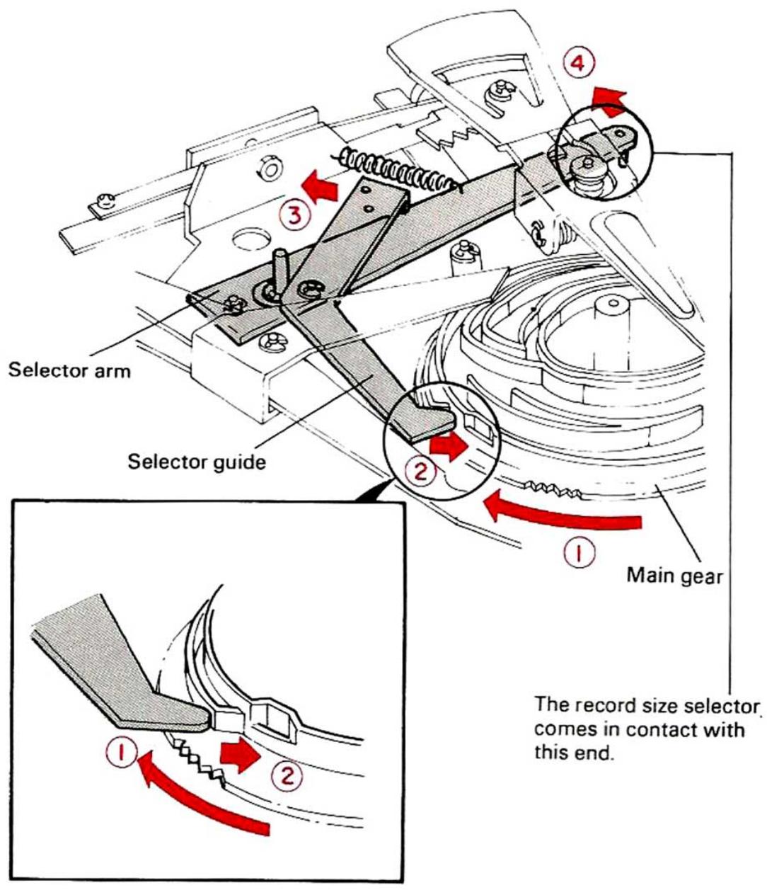
Fig. 4-1 Selector Arm and Selector Guide
OPERATION OF MECHANISM
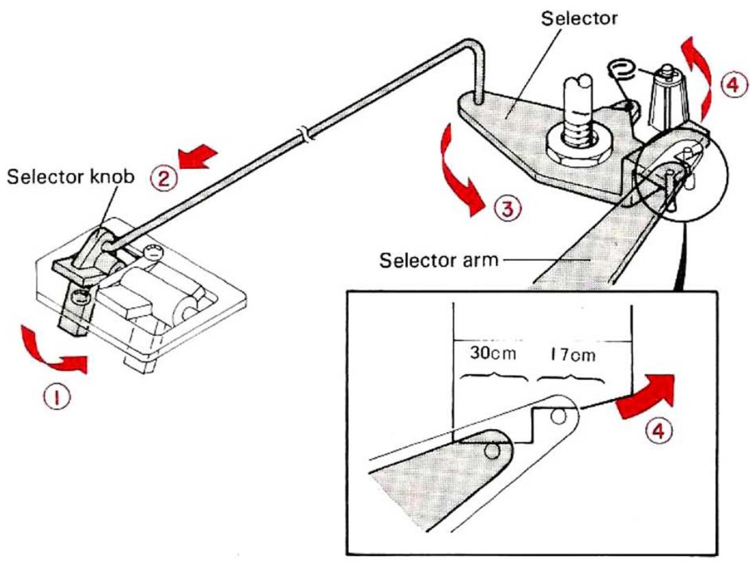
Fig. 4-2 Record Size Selector
When the record size selector knob is tilted for 30~cm record side (direction 1), the selector is turned in direction 3 and 4. The selector arm comes in contact with the "30 cm" position of the selector (Fig. 4-2).
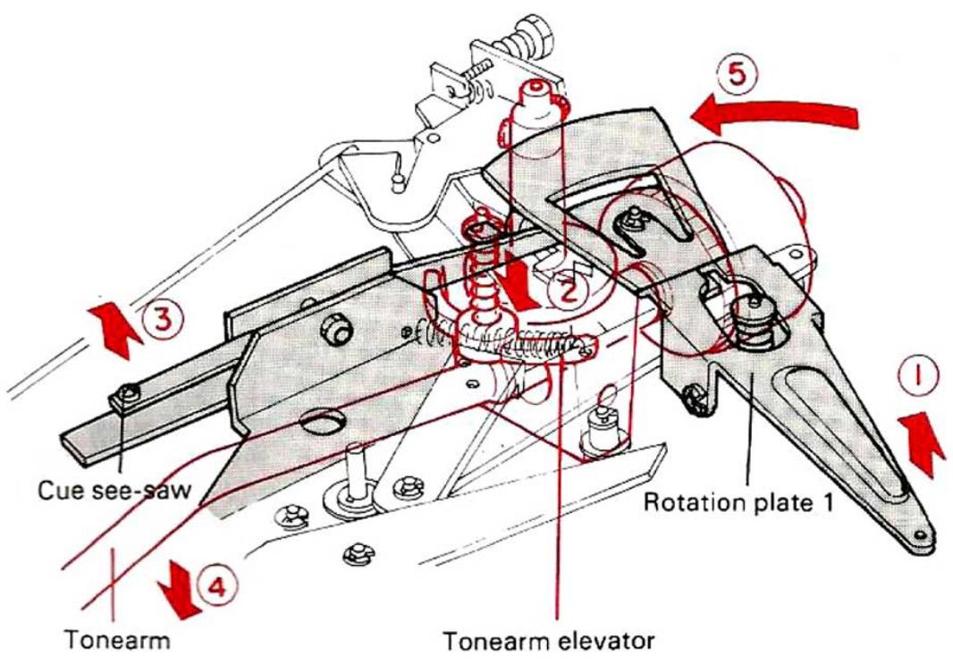
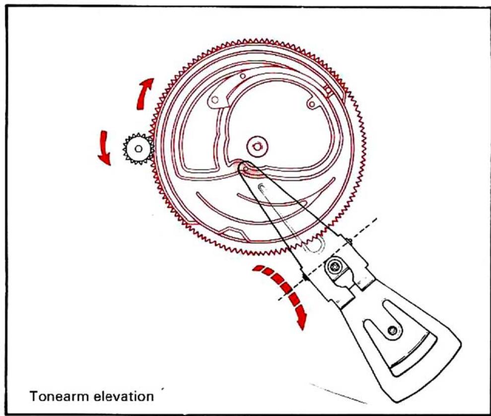
Fig. 5 Elevation of Tonearm
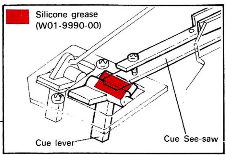
As the main gear rotates, the depth of the groove in which rotation plate 1 is engaged becomes shallower and rotation plate 1 rises in direction ① . The cue see-saw also moves in direction ② to lift the tonearm elevator, resulting in the elevation of the tonearm (Fig. 5).
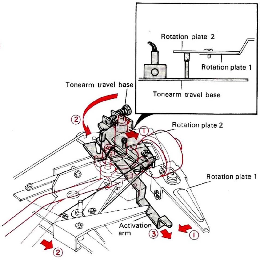
Fig. 6 Shifting of Tonearm
Rotation plate 1 moves in direction ① as the main gear rotates. The tonearm travel base also moves in direction ① due to the friction between rotation plate 2 and the boss on the travel base. As a result of this motion, the travel base itself moves in direction ② to shift the tonearm. The travel base stops when it comes in contact with the "30 cm" or "17 cm" position of the selector which is determined by the selector knob (Fig. 6). The activation arm which is coupled with the travel base moves in direction ③ (Fig. 6) to make the AUTO-CUT operation, explained later in section 3, possible.
OPERATION OF MECHANISM
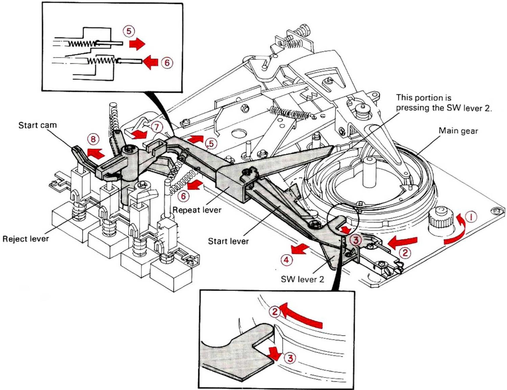
Fig. 7 Return of Start lever, Start cam and Reject cam
When the main gear rotates further in direction ②, the outermost end of the main gear presses the start lever in direction ③ and the start lever turns in directions ④ and ⑤. As a result, the start cam is released and turned in directions ⑦ and ⑧ by the spring and the repeat lever moves in direction ⑥ to return the reject lever, start lever and repeat lever in their original positions (Fig. 7).
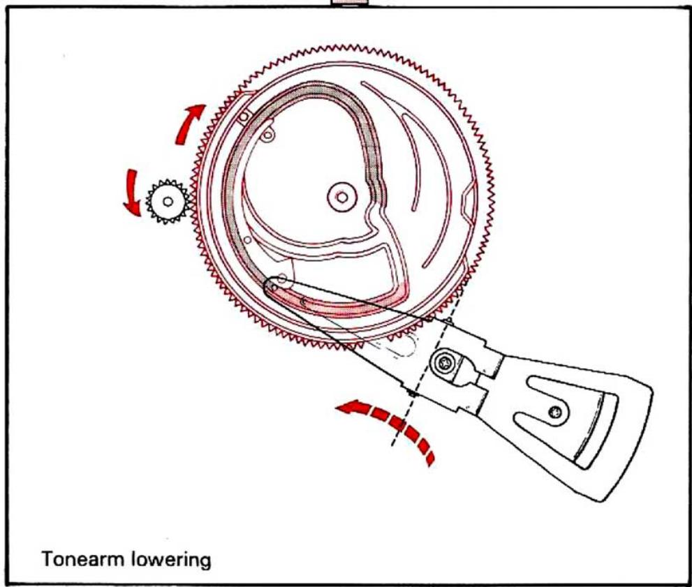
While the main gear is rotating, the SW lever is pushed outward by the part under the teeth of the main gear, so that the sensitive switch is kept turned ON even of the start lever moves in direction 4 (Fig. 7). When the outermost end of the main gear comes into contact with the selector guide, the selector guide is turned in directions 2 and 3. Therefore, the selector arm is drawn in direction 4 to release the end of the selector arm from the travel base. As a result of this operation, the tonearm can move free from the mechanism (Fig. 8). As the groove of the main gear with which rotation plate is engaged becomes deep, rotation plate moves in direction 5. The cue see-saw moves in directions 6 and 7 under its own weight and the elevation plate which contacts the cue see-saw is lowered in direction 8, thus the tonearm descends in direction 9 (Fig. 8).
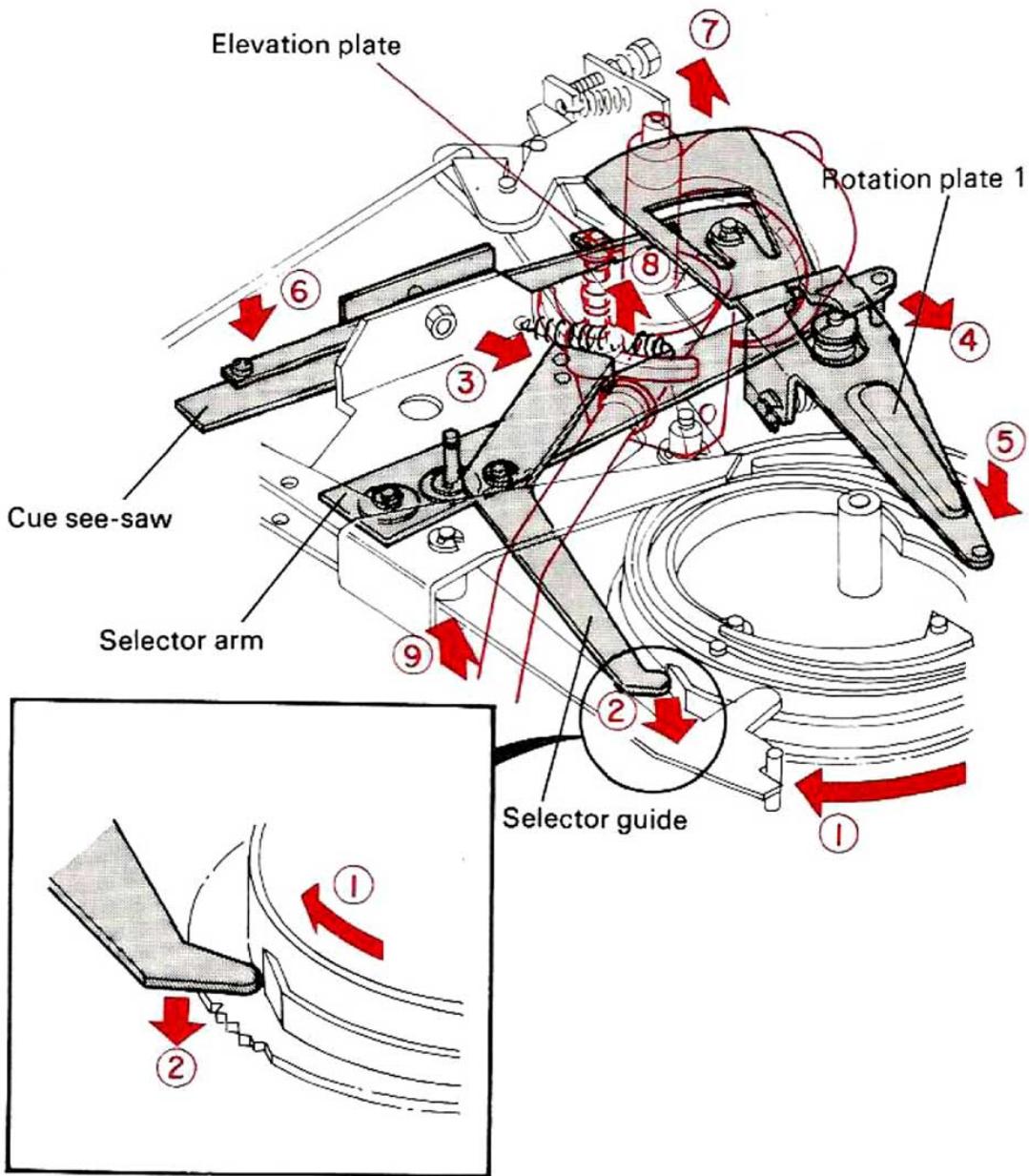
Fig. 8 Lowering of Tonearm and Return of Selector guide and Selector arm
OPERATION OF MECHANISM
When the main gear rotates one revolution, the toothless part of the main gear comes to the position of the turntable retainer gear. The clutch plate and the clutch guide are pushed back by the clutch lever in position so that it doesn't project from the toothless part, which means that the main gear is completely separated from the turntable retainer gear and it stops (Fig. 9).
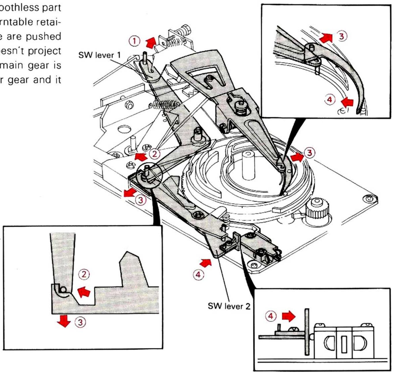
Fig. 9 SW lever 1 and SW lever 2
2.CUT Mode
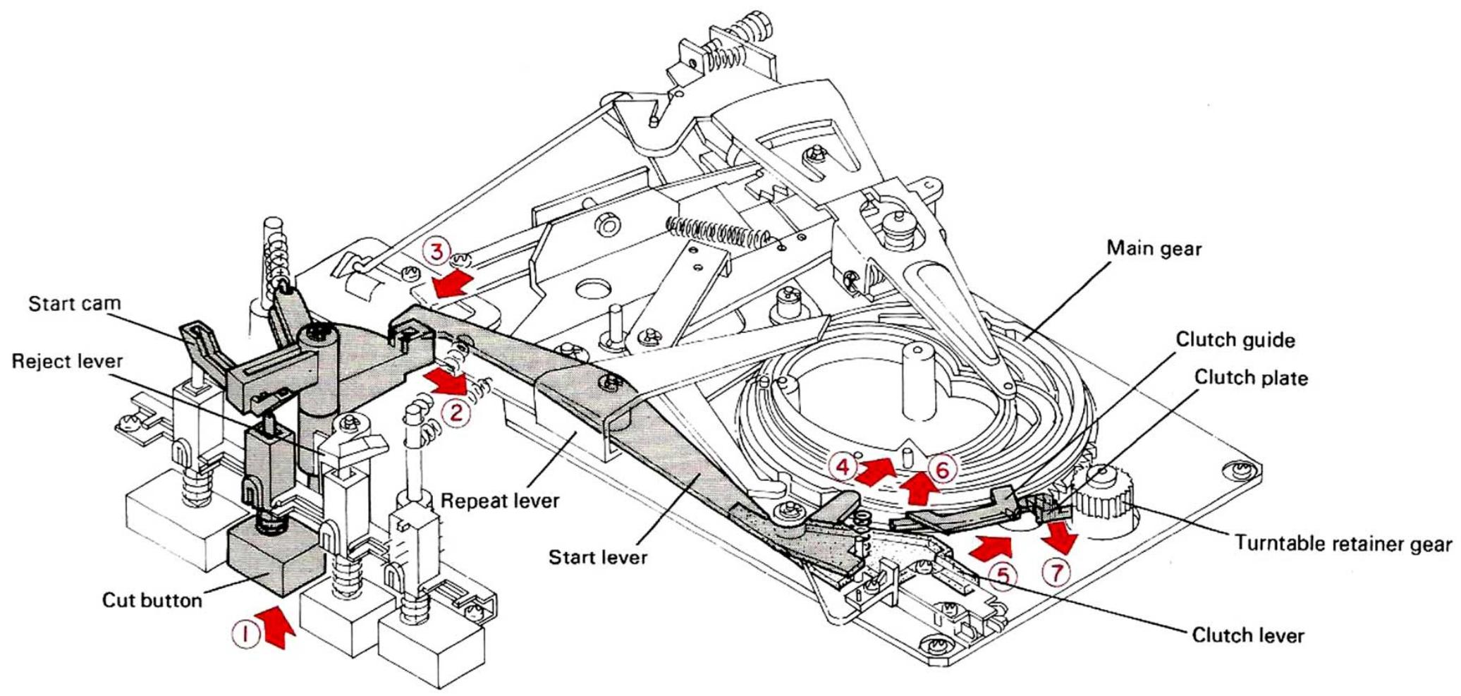
Fig. 10 When the CUT Button is Pressed
When the cut button is pressed, the start cam rotates in direction 2 for about 20^ . The start lever turns in directions 3 and 4 as in the PLAY mode to push the clutch lever in direction 5. The clutch guide and the clutch plate move in di
rections ⑥ and ⑦ respectively and engage with the turntable retainer gear to rotate the main gear. But in this case, as the reject lever is not coupled with the start cam, the repeat lever does not move (Fig. 10).
OPERATION OF MECHANISM
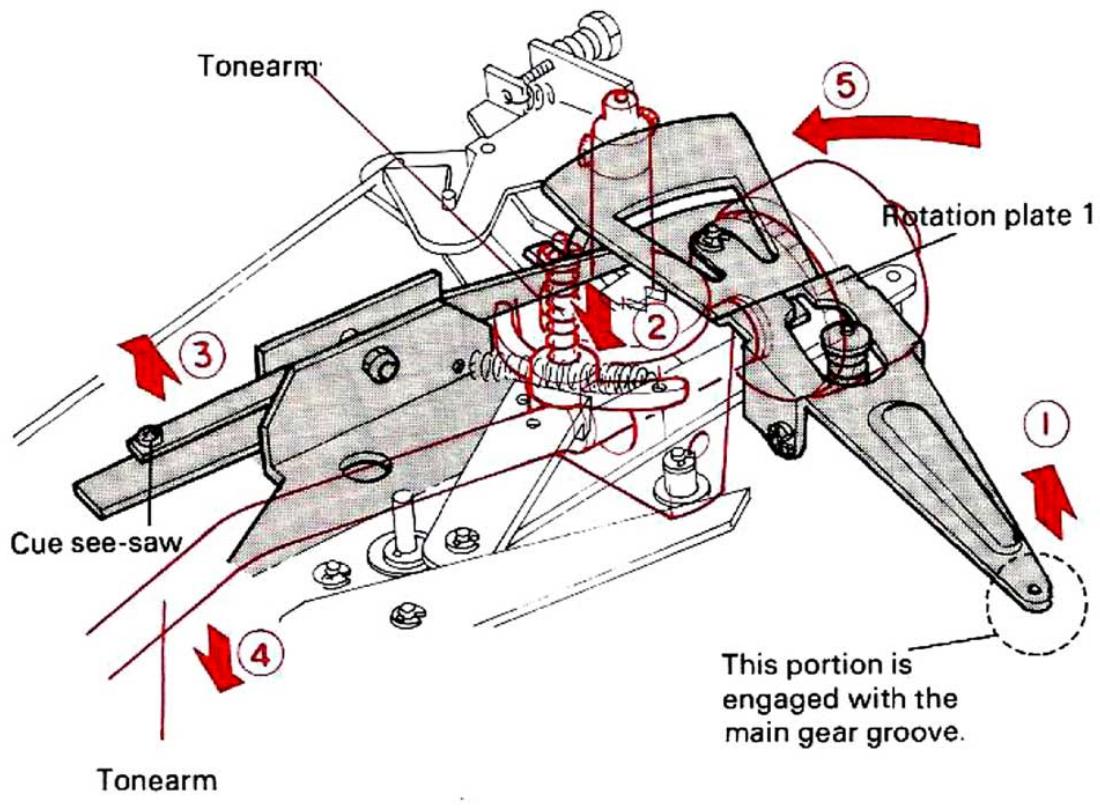
Fig. 11 Elevation of Tonearm
As the main gear begins to rotate, the depth of the main gear groove where the rotation plate 1 follows becomes shallower and the rotation plate 1 moves in direction ① . Rotation plate 1 raises the tonearm elevator and the cue seesaw in directions ② and ③ respectively to raise the tonearm up (direction ④ ). Right after this motion, rotation plate 1 starts to rotate in direction ⑤ due to the action of the main gear (Fig. 11).
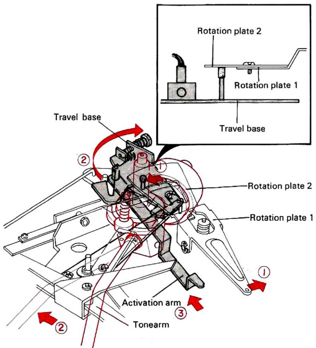
Fig. 12 Return of Tonearm
Rotation plate 1 rotates in direction ① due to the main gear's rotation and rotation plate 2 rotates in the same direction. The tonearm travel base itself moves in direction ② due to the friction between the boss of the travel base and rotation plate 2. The tonearm coupled with the travel base moves in direction ② until the tonearm comes above the arm rest. This operation is opposite of that in the PLAY mode (Fig. 12).
The activation arm coupled with the travel base returns in direction ③ (Fig. 12).
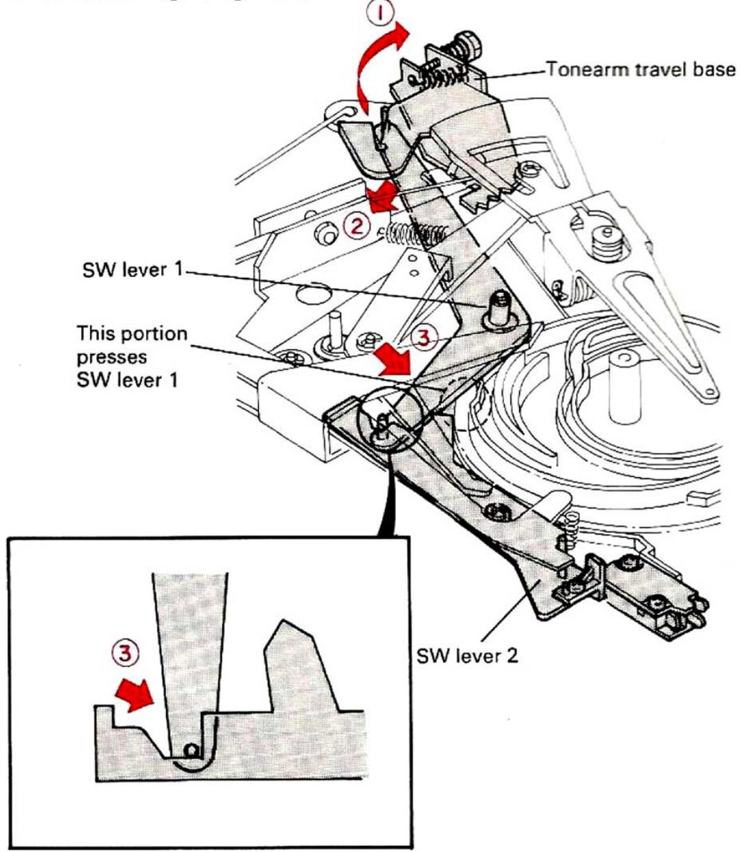
Fig. 13 Return of SW lever 1
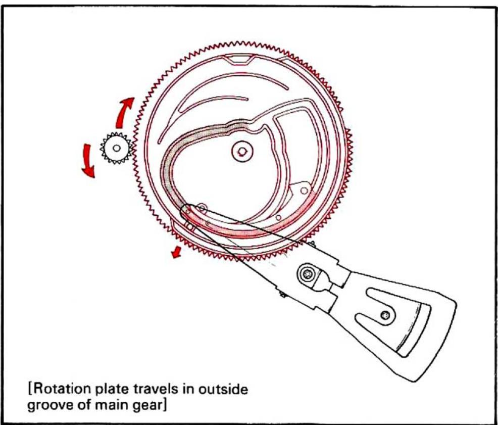
When the travel base moves in direction ①, SW lever 1 moves in directions ② and ③ to unlock SW lever 2 from SW lever 1. However, as SW lever 2 is pushed outward by the main gear, the sensitive switch is kept turned ON (Fig. 13). Rotation plate 1 goes along the outer groove of the main gear as it rotates. This operation differs from that in the PLAY mode. In the PLAY mode, as the repeat lever is coupled with the start lever, the switching lever enters the inner groove of the main gear. In the CUT mode, as the repeat lever does not move, the switching lever does not enter the inner groove (Fig. 14).
When the outermost end of the main gear comes to the position of the selector guide (in direction ①), the selector guide moves in directions ② and ③, so that the selector arm is drawn in direction ④ by the spring and the selector arm returns to its original position (Fig. 15).
OPERATION OF MECHANISM
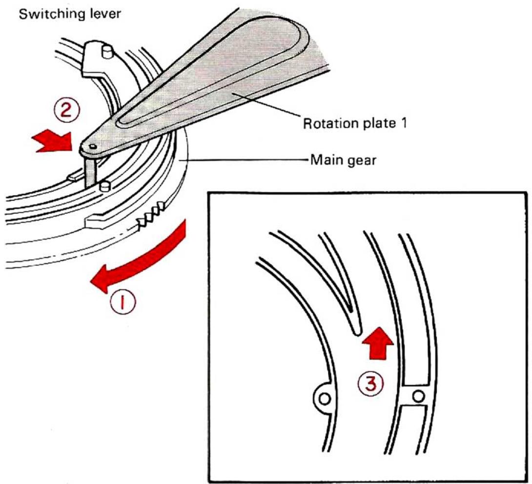
Fig. 14 Switching lever in CUT mode
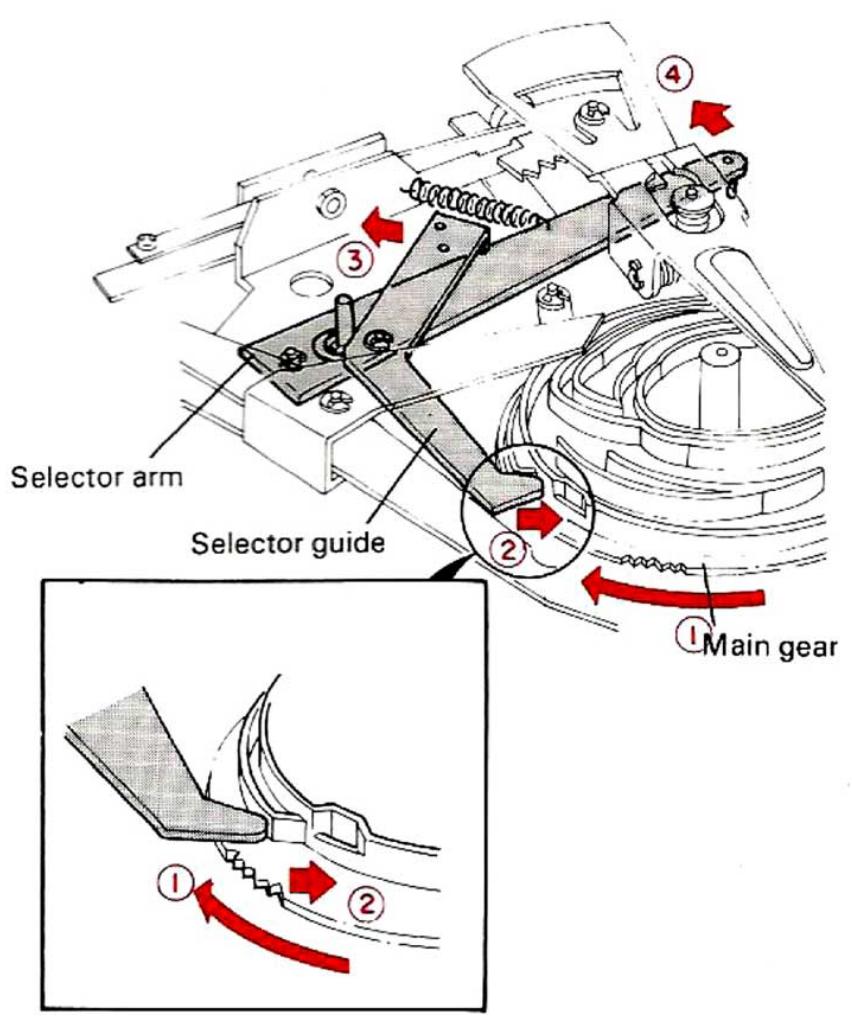
Fig. 15 Return of Selector guide and Selector arm
When the outermost end of the main gear comes to the position of the start lever 1 and 2, the start lever and the start cam are reset (Fig. 16).
When the main gear rotates by 4/5 turns, the depth of the groove of the main gear becomes deeper to allow the tonearm to be lowered on the arm rest. When the main gear rotates by one turn, the toothless part of the main gear comes to the position of the turntable retainer gear. In this case, as the clutch plate and the clutch guide is hidden below the main gear so that there are nothing that can engage with the turntable retainer gear, the main gear is completely separated from the turntable retainer, and the main gear stops. As the tonearm is positioned on the arm rest, the SW lever is unlocked so that the sensitive switch is turned OFF when the main gear stops.
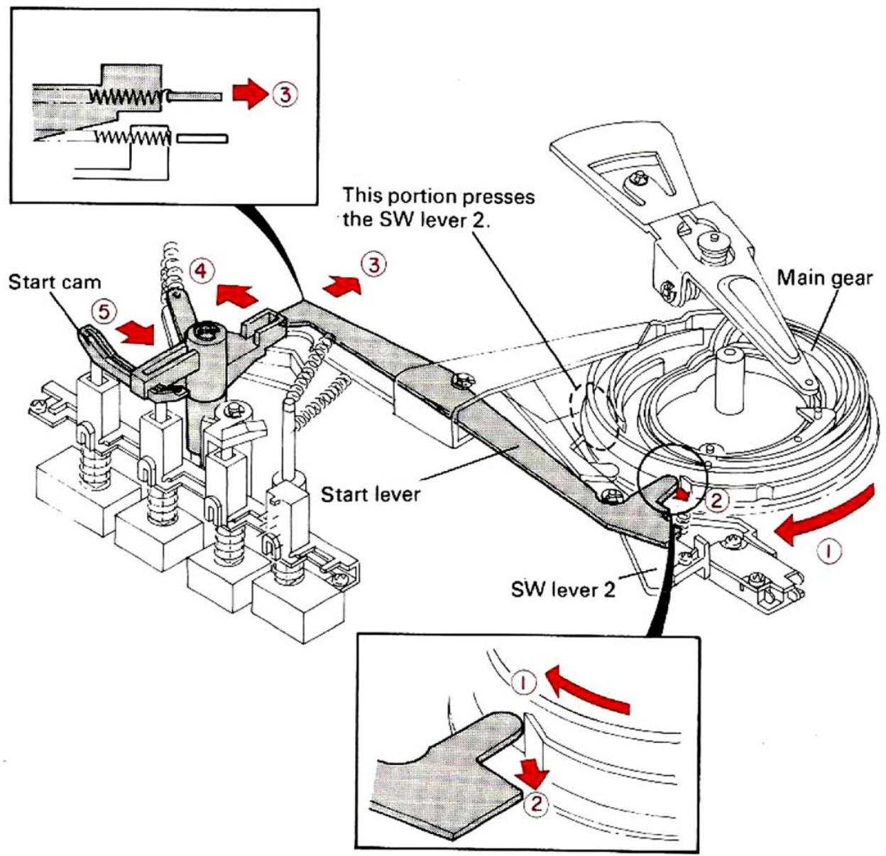
Fig. 16 CUT Switch Reset
3. AUTO CUT mode
When the stylus reaches the lead out groove of the record after completion of playback, the activation arm (refer to Fig. 6) pushes the clutch plate (refer to Fig. 10) located in the main gear and the clutch plate is engaged with the turntable retainer.
After this operation, the unit follows the same procedure as when the cut button is pressed.
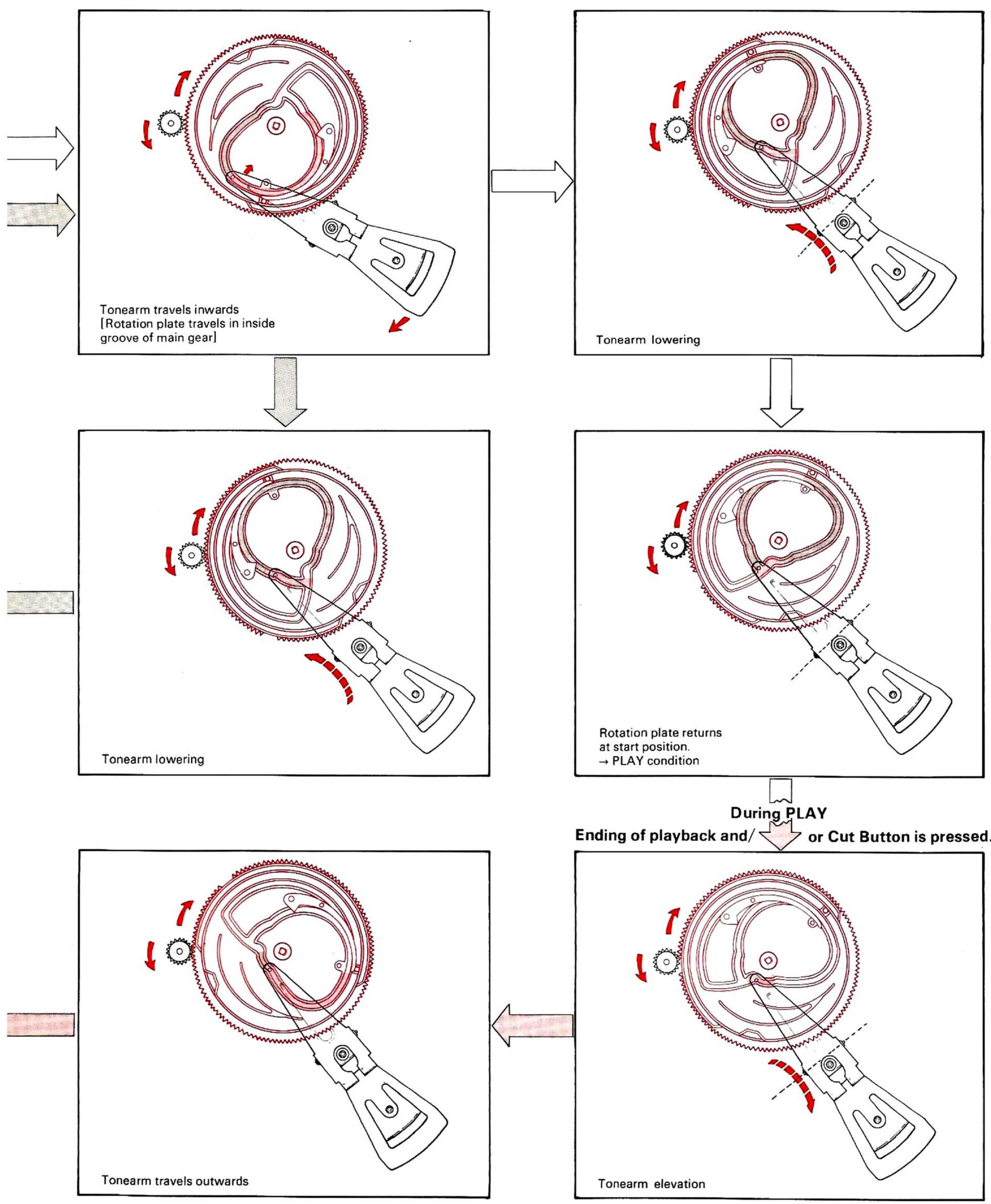
AUTOMATIC MECHANISM OPERATION
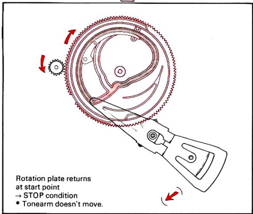
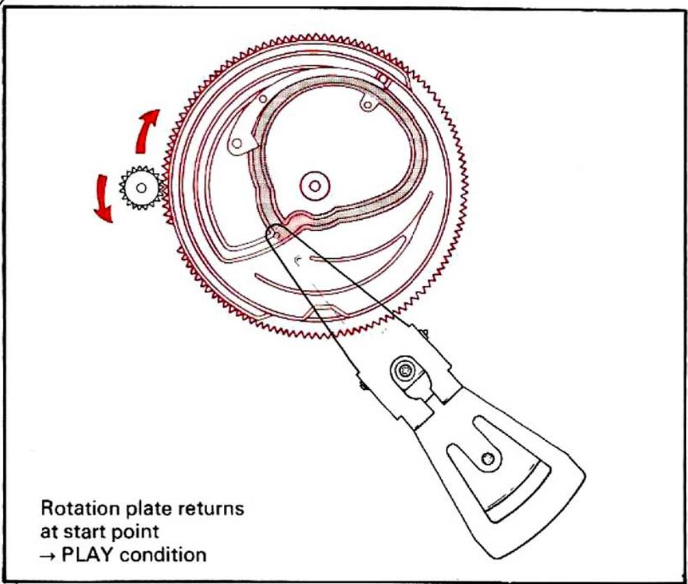
4. Main gear and Rotation plate travelling
PLAY button Pressed


Tonearm travels outwards (REPEAT)
* Tonearm doesn't move laterally (PLAY)

AUTOMATIC MECHANISM OPERATION
ADJUSTMENT
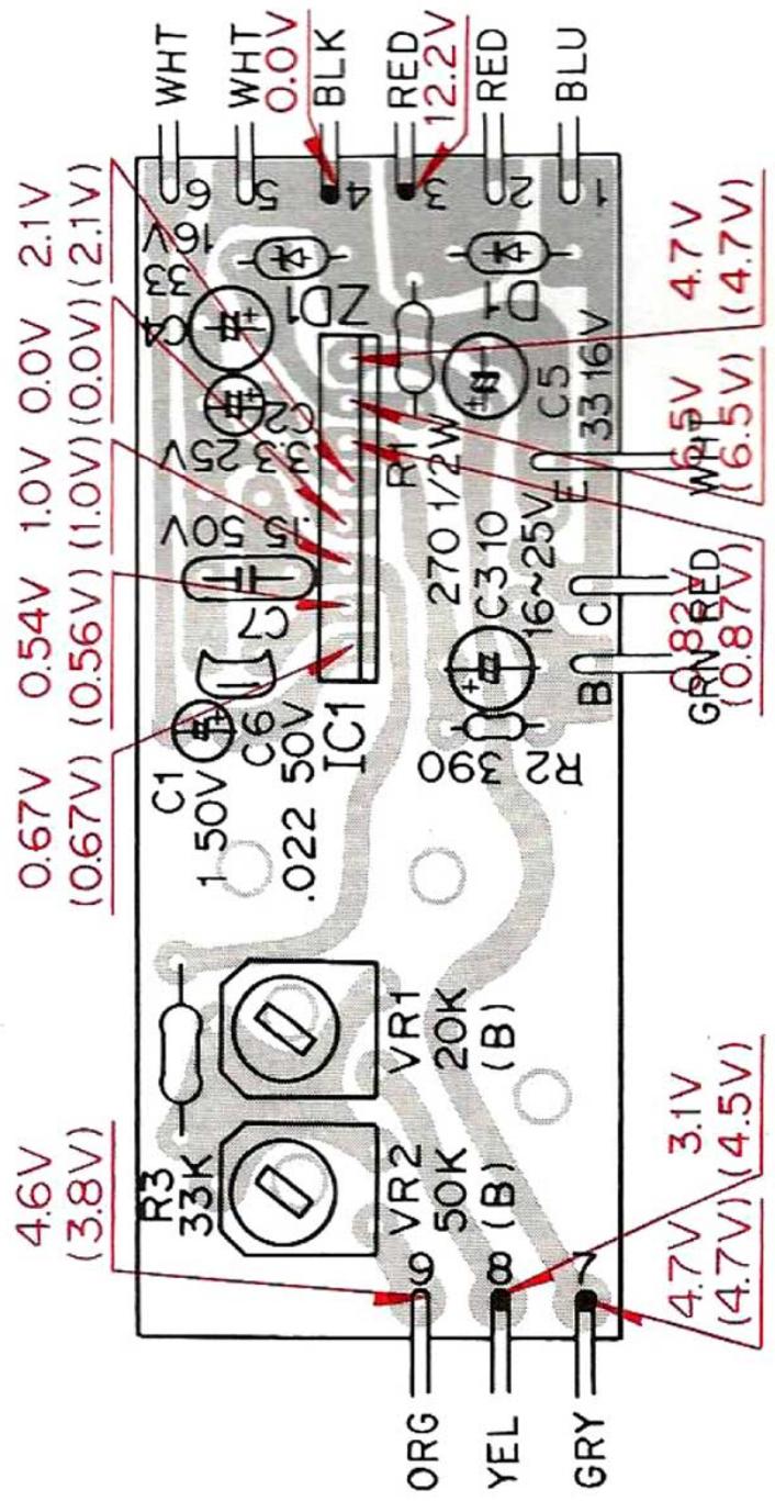
1. Motor speed adjustment
If the proper speed cannot be obtained by adjustment of the SPEED ADJ control on the operation panel, readjust the trimming potentiometers on the motor PC board as follows. (Refer to the figure below.)
1) Level the turntable.
2) Center the SPEED ADJ knob.
3) Set the SPEED selector to "33".
4) Adjust the trimming potentiometer for 33 rpm (Lower) through the access hole until the striped pattern of the turntable platter stops.
5) Set the SPEED selector to "45".
6) Similarly adjust the trimming potentiometer for 45rpm (upper) through the access hole until the striped pattern of the turntable platter stops.
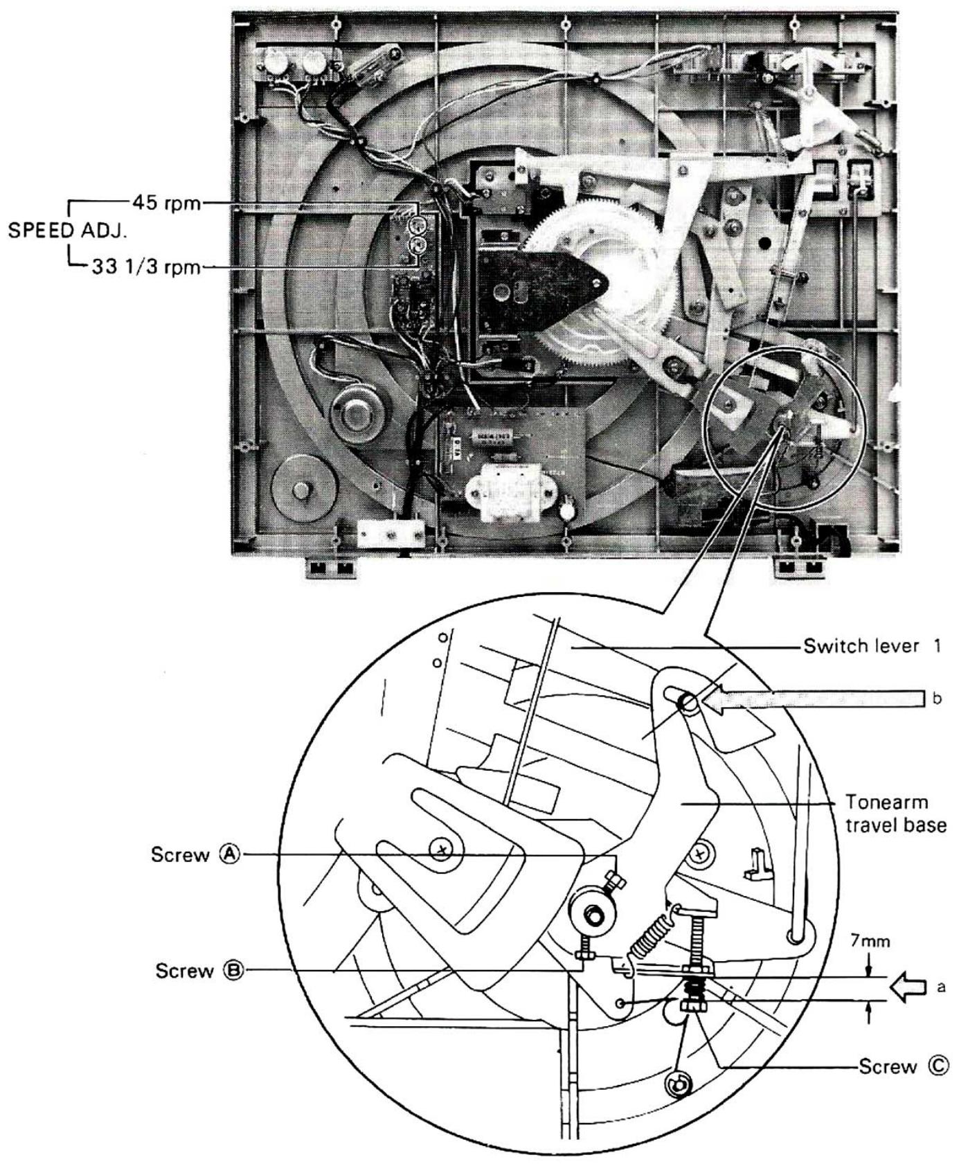
Adjustment of AUTO-IN Position
30 cm record..... 14.6 14.85 cm from center
17 cm record..... 8.4 8.6 cm from center
- Secure the tonearm on the arm-rest.
- Loosen screws A and B
- Adjust screw to obtain a 7 mm space at a.
- Turn the travel base until the projection of the SW lever 1 reaches point b.
- Tighten screws A and B (Lock the screws after checking the AUTO-IN position).
*When the AUTO-IN position has been adjusted, be sure to readjust the AUTO RETURN position.
Adjustment of AUTO-RETURN Position
30 cm and
17 cm records .. 6.1 cm ±0.5 cm from center
- Secure the tonearm on the arm-rest.
- Turn screw and adjust the AUTO-RETURN position (Lock the screw after adjustment).
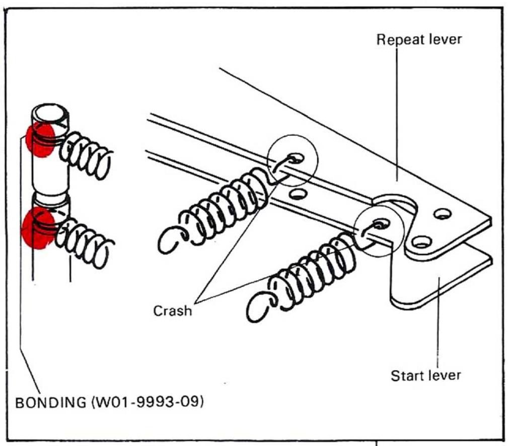
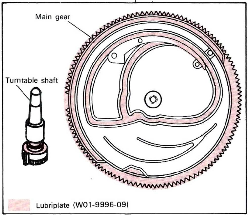
LUBRICATION
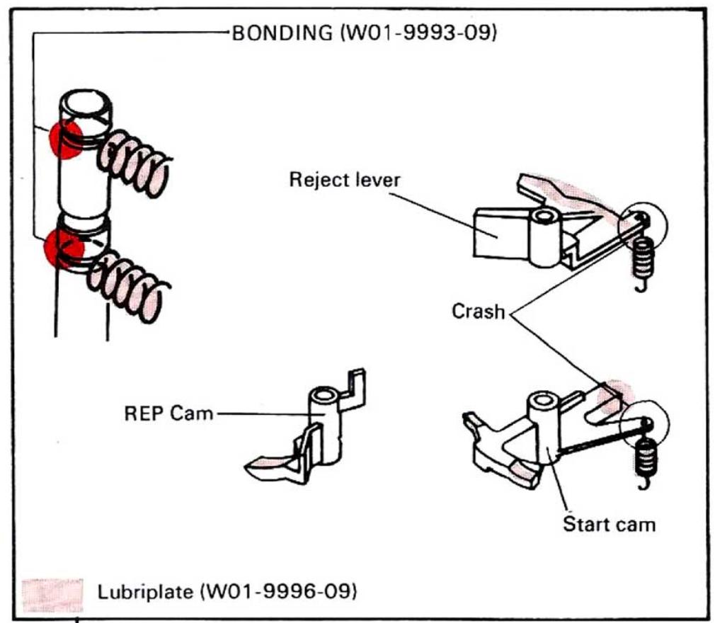
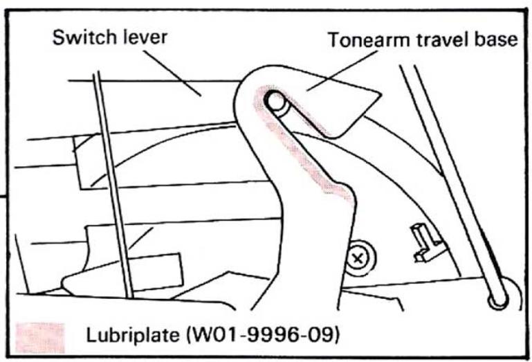
| Description | Parts No. |
| Lubriplate grease | W01-9996-09 |
| Silicone grease | W01-9990-00 |
| Adhesive | W01-9993-09 |
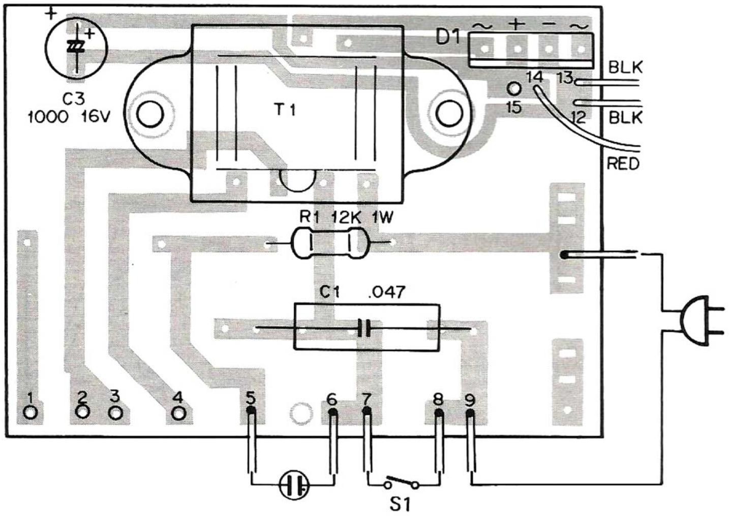
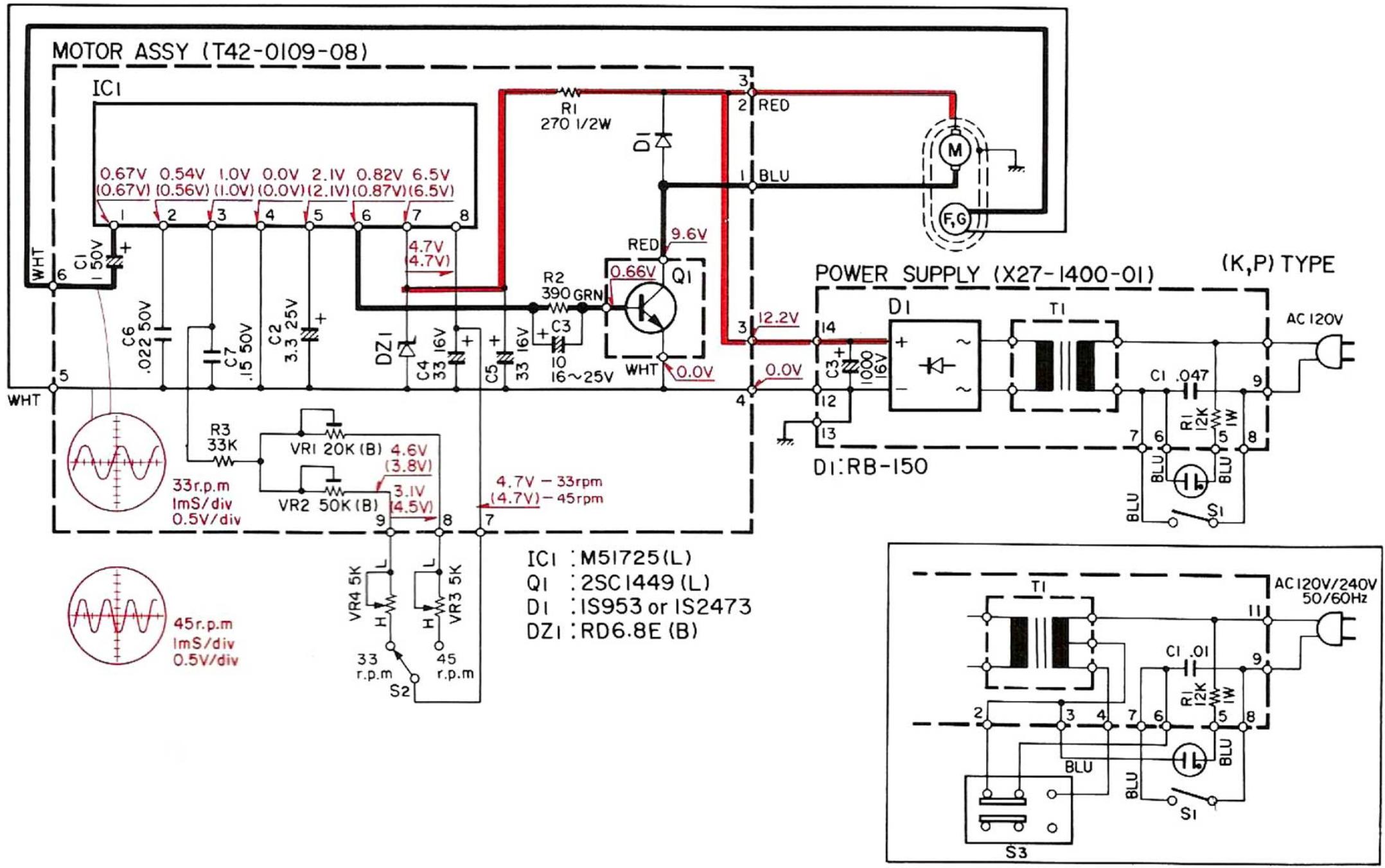
POWER SUPPLY (X27-1400-02~06)
Component Side View
Component Side View
MOTOR (T42-0109-08)
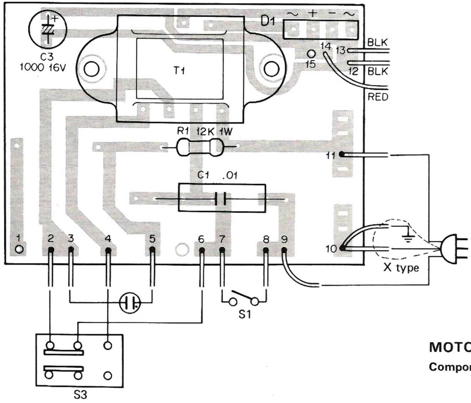
POWER SUPPLY (X27-1400-01, -07)
Component Side View
SCHEMATIC DIAGRAM/PACKING
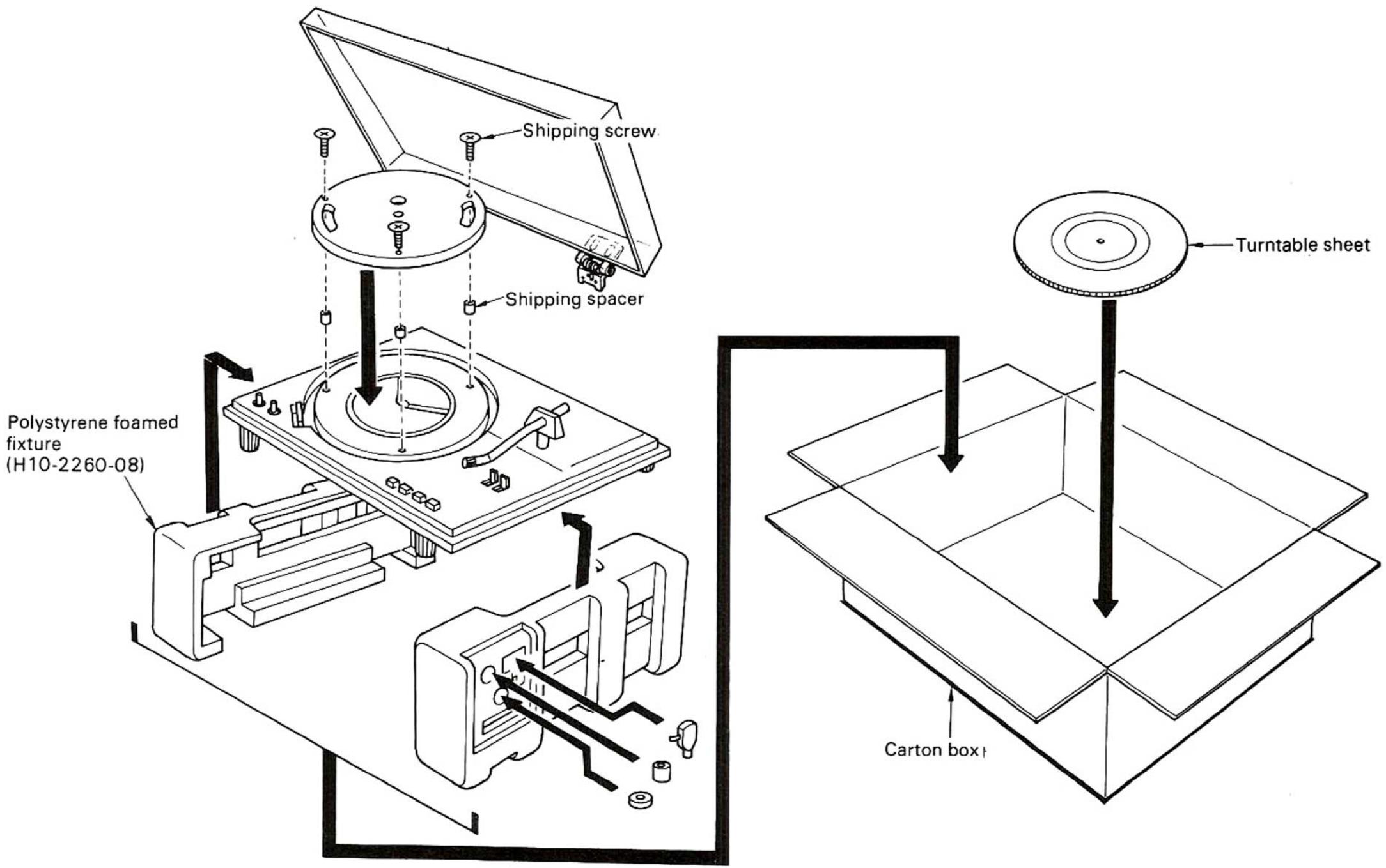
PACKING
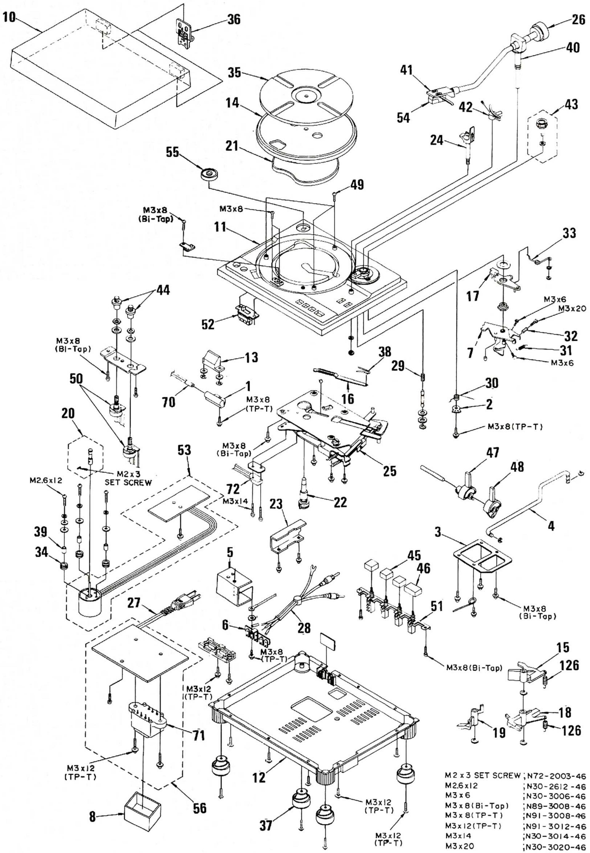
EXPLODED VIEW
A
B
EXPLODED VIEW
C
D
| Ref. No.参照番号 | Parts No.部 品 署 号 | Description部品名/规格 | Re-marks備考 |
| KD-2100 |
| 1 2A2 2B3 2B4 2B5 2A6 3A7 2B8 3A9 1A | - - - - - - - - - - - - - - - - - - - - - - - - - - - - - - - - - - - - - - - - - - - - - - - - - - - - - - - - - - - - - - - - - - - - - - - - - - - - - - - - - - - - - - - - - - - - - - - - - - - - - LUG TYPE TERMINAL ASSYTRAVEL BASESHIELD CASESWITCH STOPPER | LAMP HOLDERI.F.C.CAMLEVER ANGLESELECTOR LOADSHIELD PLATE | * *KMSwXUPLHJT |
| 10 1A11 1A11 1A11 1A11 1A11 1A11 1A11 1A11 1A11 3A | A53-0321-08A02-0330-08A02-0330-08A02-0330-08A02-0330-08A02-0330-08A02-0331-08A40-0544-08B42-0009-04B46-0055-20B46-0060-00B46-0061-20B46-0062-20B46-0063-00B46-0064-00B50-2373-00B50-2373-00B50-2373-00B50-2373-00B50-2374-00B50-2374-00B50-2375-00B59-0018-00B19-0508-08D02-0031-08D10-0848-08D10-0849-08D10-0850-08SELECTORSSTART CAMREPEAT CAMPULLEY ASSYBELTTURNTABLE RETainer ASSYSTOPPER | TURNTABLE COVERCABINET BOARDCABINET BOARDCABINET BOARDCABINET BOARDCABINET BOARDCABINET BOARDCABINET BOARDCABINET BOARDCABINET BOARDCABINET BOARDCABINET BOARDCABINET BOARDCABINET BOARDCABINET BOARDCABINET BOARDCABINET BOARDCABINET BOARDCABINET BOARDCABINET BOARDCABINET BOARDCABINET BOARDCABINET BOARDCABINET BOARDCABINET BOARDCABINET BOARDCABINETBOARD CLOUD SPRING | UHXUHMPWSTYPUSWTPUSWTPUSWTPUSWTPUSWTPUSWTPUSWTPUSWTPUSWTPUSWTPUSWTPUSWTPUSWTPUSWTPUSWTPUSWTPUSWTPUSWTPUSWTPUSWTPUSWTPUSWTPUSWTPUSWTPUSWTPUSWTPUSWTPUSWTPUSWTPUSWTPUSWTPUSWTPUSWTPUSWTPusWTPUSWTPUSWTPUSWTPUSWTPUSWTPUSWTPUSWTPUSWTPUSWTPUSWTPUSWTPUSWTPUSWTPUSWTPUSWTPUSWTPUSWTPUSWTPUSWTPUSWTPUSWTPUSWTPUSWTPUSWTPUSWTPUSWTPUSWTPUSWTPUSWTPUSWTPUSWTPUSWTPUS |
| Ref. No.参照番号 | Parts No.部 品 署 号 | Description部品名/规格 | Remarks備考 |
| 34 2A | G13-0465-08 | RUBBER CUSHION | * |
| 35 1A | G16-0324-03 | TURNTABLE SHEET | K |
| 35 1A | G16-0337-03 | TURNTABLE SHEET | *M |
| 35 1A | G16-0337-03 | TURNTABLE SHEET | ST |
| 35 1A | G16-0337-03 | TURNTABLE SHEET | WX |
| 35 1A | G16-0337-03 | TURNTABLE SHEET | UP |
| 35 1A | G16-0337-03 | TURNTABLE SHEET | LH |
| - | H01-2398-08 | CARTON BOX | W |
| - | H01-2399-08 | CARTON BOX | T |
| - | H01-2400-08 | CARTON BOX | P |
| - | H01-2401-08 | CARTON BOX | *K |
| - | H01-2401-08 | CARTON BOX | MS |
| - | H01-2401-08 | CARTON BOX | XU |
| - | H01-2401-08 | CARTON BOX | LH |
| - | H10-2266-08 | POLYSTYRENE FOAMED | * |
| - | H25-0078-04 | POLYETHYLENE BAG | |
| - | J31-0443-08 | SHIPPING SPACER | * |
| 36 1A | J50-0317-08 | HINGE ASSY | * |
| 37 3A | J02-0337-08 | INSULATOR ASSY | * |
| 38 2B | J12-0316-08 | SNAP PIN | * |
| 39 2A | J31-0442-08 | COLLAR | * |
| 40 1B | J91-0146-08 | PU ASSY | *M |
| 40 1B | J91-0146-08 | PU ASSY | SW |
| 40 1B | J91-0146-08 | PU ASSY | XU |
| 40 1B | J91-0146-08 | PU ASSY | LH |
| 40 1B | J91-0147-08 | PU ASSY | KP |
| 40 1B | J91-0147-08 | PU ASSY | T |
| 41 1B | J92-0057-05 | HEAD SHELL | * |
| 42 1B | J99-0209-08 | ELEVATION PLATE | * |
| 43 1B | K21-0613-08 | I.F.C.KNOB ASSY | * |
| 44 2A | K23-0650-08 | KNCB(SPEED) | * |
| 45 2B | K29-0695-08 | KNCB(PUSHBUTTON) | * |
| 46 2B | K29-0696-08 | KNOB(PLAY) | * |
| 47 2B | K29-0697-08 | KNOB(CUE) | * |
| 48 2B | K29-0698-08 | KNOB(SELECT) | * |
| 49 1B | N09-0919-08 | SHIPPING SCREW | * |
| VR1 2 | R01-2302-08 | TRIMMING POT 5K FIG50 | * |
| S1 3B | S42-4303-08 | PUSH SWITCH FIG51 | * |
| S3 2A | S31-2308-08 | SLIDE SWITCH FIG52 | WL |
| S3 2A | S31-2308-08 | SLIDE SWITCH FIG52 | H |
| S3 2A | S31-2309-08 | SLIDE SWITCH FIG52 | MS |
| S3 2A | S31-2309-08 | SLIDE SWITCH FIG52 | XU |
| S3 2A,3A | T42-0109-08 | MOTOR ASSY | * |
| S4 1B | T21-0067-05 | CARTRIDGE V39MK3 | MS |
| S4 1B | T21-0067-05 | CARTRIDGE V39MK3 | WX |
| S4 1B | T21-0067-05 | CARTRIDGE V39MK3 | UL |
| S4 1B | T21-0067-05 | CARTRIDGE V39MK3 | H |
| S5 1A | W01-0322-08 | EP ADAPTER | * |
| S6 3A | x27-1400-01 | POWER SUPPLY PCB ASSY | *K |
| S6 3A | x27-1400-02 | POWER SUPPLY PCB ASSY | MU |
| S6 3A | x27-1400-03 | POWER SUPPLY PCB ASSY | S |
| S6 3A | x27-1400-04 | POWER SUPPLY PCB ASSY | T |
| S6 3A | x27-1400-05 | POWER SUPPLY PCB ASSY | WL |
| S6 3A | x27-1400-05 | POWER SUPPLY PCB ASSY | H |
| S6 3A | x27-1400-06 | POWER SUPPLY PCB ASSY | X |
| S6 3A | x27-1400-07 | POWER SUPPLY PCB ASSY | P |
| POWER SUPPLY (X27-1400-xx) |
| 70 2A | B30-0726-08 | NEON LAMP | *K |
PARTS LIST
| Ref. No.参照番号 | Parts No.部品番号 | Description部品名/规格 | Remarks備考 |
| 70 2A | B30-0726-08 | NEON LAMP | MS |
| 70 2A | B30-0726-08 | NEON LAMP | TW |
| 70 2A | B30-0726-08 | NEON LAMP | XU |
| 70 2A | B30-0726-08 | NEON LAMP | LH |
| 70 2A | B30-0733-08 | NEON LAMP | P |
| C1 | C90-0339-08 | ELECTRO 1000UF 16WV | * |
| C2 | C91-0335-08 | FILM 0.047UF 200VAC | K |
| C2 | C91-0336-08 | FILM 0.047UF 125VAC | P |
| C2 | C91-0337-08 | FILM 0.047UF | MS |
| C2 | C91-0337-08 | FILM 0.047UF | WX |
| C2 | C91-0337-08 | FILM 0.047UF | UL |
| C2 | C91-0337-08 | FILM 0.047UF | H |
| C2 | C91-0338-08 | FILM 0.022UF | T |
| T1 | L01-6301-08 | POWER TRANSFORMER FIG71 | *K |
| T1 | L01-6302-08 | POWER TRANSFORMER FIG71 | T |
| T1 | L01-6304-08 | POWER TRANSFORMER FIG71 | MS |
| T1 | L01-6304-08 | POWER TRANSFORMER FIG71 | WX |
| T1 | L01-6304-08 | POWER TRANSFORMER FIG71 | UL |
| T1 | L01-6304-08 | POWER TRANSFORMER FIG71 | H |
| T1 | L01-6307-08 | POWER TRANSFORMER FIG71 | P |
| S2 2A | S50-1313-08 | SENSITIVE SWITCH FIG72 | *K |
| S2 2A | S50-1313-08 | SENSITIVE SWITCH FIG72 | P |
| S2 2A | S50-1314-08 | SENSITIVE SWITCH FIG72 | MS |
| S2 2A | S50-1314-08 | SENSITIVE SWITCH FIG72 | Tw |
| S2 2A | S50-1314-08 | SENSITIVE SWITCH FIG72 | XU |
| S2 2A | S50-1314-08 | SENSITIVE SWITCH FIG72 | LH |
| D1 | v11-5100-90 | RB-150 | * |
| MOTOR ASSY (T42-0109-08) |
| C1 | C24-1710-51 | ELECTRO 1UF 50WV | |
| C2 | C24-1433-51 | ELECTRO 3.3UF 25WV | |
| C3 | C24-1210-61 | ELECTRO 10UF 16WV | |
| C4,S | C24-1233-61 | ELECTRO 33UF 16WV | |
| C6 | C46-1722-35 | MYLAR 0.033UF J | |
| C7 | C46-1715-45 | MYLAR 0.15UF J | |
| R1 | R43-5327-15 | RD 270 J 2H | |
| VR1 | R12-3306-08 | TRIMMING POT 20K | * |
| VR2 | R12-4304-08 | TRIMMING POT 50K | * |
| DZ1 | v11-1201-90 | RD6.8E | * |
| D1 | v11-9974-05 | 1S953 | |
| IC1 | v30-0431-10 | M51725L | * |
| Q1 | v03-1449-00 | 2SC1449(L) | |
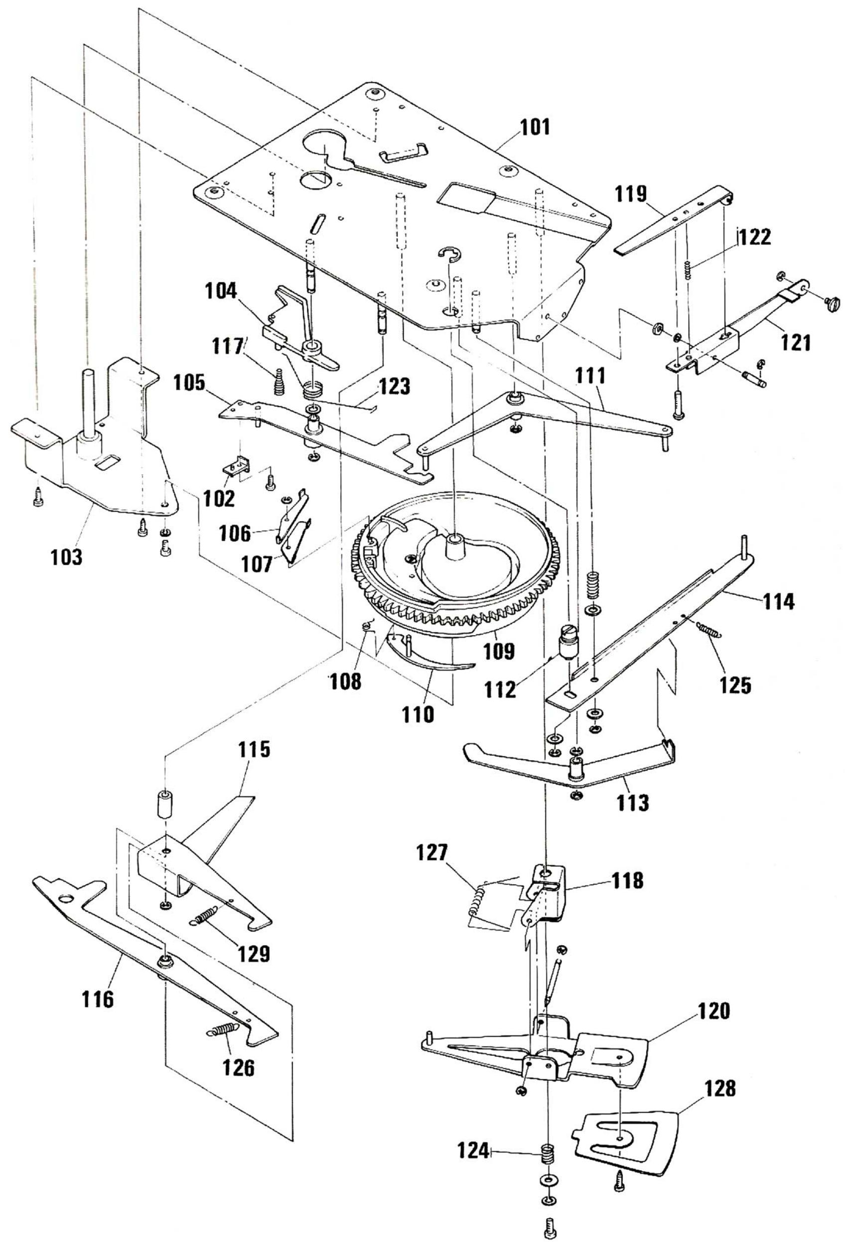
| AUTOMATIC MECHANISM (D40-0483-08) |
| 101 1D | - | SUB CHASSIS | |
| 102 2C | - | SWITCH LEVER TIP | |
| 103 2C | - | TURNTABLE SHAFT BOARD | |
| 104 1C | - | CLUTCH LEVER | |
| 105 1C | - | SWITCH LEVER(2) | |
| 106 2C | - | CLUTCH PLATE | |
| 107 2C | - | CLUTCH GUIDE | |
| 108 2C | - | TORSION SPRING | |
| 109 2D | - | MAIN GEAR | |
| 110 2D | - | SWITCHING LEVER | |
| 111 1D | - | SWITCH LEVER(1) | |
| 112 2D | - | ECCENTRIC SHAFT | |
| 113 2D | - | SELECTOR GUIDE | |
| 114 2D | - | SELECTOR ARM | |
| 115 2C | - | REPEAT LEVER | |
| 116 3C | - | START LEVER | |
| 117 1C | - | CLUTCH COIL SPRING | |
| Ref. No.参照番号 | Parts No.部 品 番 号 | Description部 品 名 / 规 格 | Re- marks 借考 |
| 118 2D119 1D120 3D121 1D122 1D123 1C124 3D125 2D126 3C127 2D128 3D129 3C | G01-0766-08G01-0767-08G01-0768-08G01-0769-08G01-0770-08G01-0771-08G01-0772-08G01-0773-08 | TURNING BASEPUSH-UP LEVERROTATION PLATE(1)CUE SEESAWLOCK PLATERLUTCH LEVER SPRINGSAFTY SPRINGSELECTOR ARM SPRINGSTART LEVER SPRINGROTATION PLATE SPRINGROTATION PLATE(2)CAM SPRING | * * * * * * |
Note:
Component and circuitry are subject to modification to insure best operation under differing local conditions. This manual is based on, the U.S. (K) standard, and provides information on regional circuit modification through use of alternate schematic diagrams, and information on regional component variations through use of parts list.
| Region | Code |
| U.S.A. | K |
| Canada | P |
| PX | U |
| Australia | X |
| Europe | W |
| England | T |
| South Africa | S |
| Other Areas | M |
| Audio Club | H |
PARTS LIST/SPECIFICATIONS
| Ref. No.
参照番号 | Parts No.
部品番号 | Description
部品名/规格 | Remarks
借考 |
| 18 1A
19 2A
19 2A
19 2A
19 2A
R221
R222
VR1,2
VR3,4
VRS,6 | A01-0608-12
A20-1979-11
A20-1979-11
A20-1979-11
A20-1979-11 | METALLIC CABINET
FRONT PANEL ASSY
FRONT PANEL ASSY
FRONT PANEL ASSY
FRONT PANEL ASSY | 3
4
XW
6 |
| R43-1333-15
R43-1368-15
R12-3301-05
R19-4305-05
R12-2302-05 | FL=PROOF RD330 J 2H
FL=PROOF RD680 J 2H
TRIMMING POT, 20K(B)
POTENTIOMETER (OUTPUT)
TRIMMING POT, 5K(B) | *
*
*
* |
① Exploded view drawing No.
② Position in exploded view.
③ Symbol of new parts.
④ Area to which parts are shipped Example: A20-1979-11 is the parts No. of FRONT PANEL ASS'Y for the "K" type products (for USA). When this column is blank, it means that the same type of parts (same parts No) are used for the products shipped to all areas.
⑤ Reference No in schematic diagram
⑥ Abbreviation of "Flame proof metal oxide film resistor". All capacitors and resistors are listed using abbreviations. Abbreviations
-
Abbreviations of capacitors (Parts No. with initial letter "C").
ELECTRO Electrolytic capacitor
LL-ELEC Low leak electrolytic capacitor
NP-ELEC Non-pole electrolytic capacitor
MICA Mica capacitor
POLYSTY Polystyrene capacitor
MYLAR Mylar capacitor
CERAMIC Ceramic capacitor
TANTAL Tantalum capacitor
MF Metallized film capacitor
OIL
The unit "UF" is used in lieu of F
-
Abbreviations of resistors (Parts No. with initial letters "R")
RC Carbon composition resistor
RD Carbon film resistor
FL-PROOF RD Flame-proof carbon film resistor
RW Wire wound power resistor
FL-PROOF RS. Flame-proof metal oxide film resistor
Rn Metal film resistor
FUSE-RESILT. Resistor with fuse function
2B Rated wattage 1/8W
2E Rated wattage 1/4W
2H Rated wattage 1/2W
3A Rated wattage 1W
3D Rated wattage 2W
3F Rated wattage 3W
3G Rated wattage 4W
3H Rated wattage 5W
All resistor values are indicated with the unit () omitted.
-
Abbreviations common to capacitors and resistors.
C ±0.25pF (Used for capacitors only)
D ±0.5pF (Used for capacitors only)
F ±1%
G ±2%
J ±5%
K ±10%
M ±20%
Z +80%. -20% (Used for capacitors only)
P +100% - 0% (Used for capacitors only)
Resistors RD (carbon composition resistors) are not listed in the parts
list. For values, refer to the schematic diagram
SPECIFICATIONS
MOTOR & TURNTABLE
Drive System Belt-Drive
Motor Frequency Generator Servo DC Motor
Turntable Platter 31 cm (12-3/16")Diameter.
Aluminum Alloy Die-Cast
Weight 0.7 kg (1.54 lbs)
Speeds 2 Speeds.33-1/3 and 45 rpm
Speed Control Range Within ± 3%
Wow & Flutter .Less than 0.04% (WRMS)
Rumble. DIN weighted better than -67 dB
TONEARM
Type Static-Balance Type, S-Shaped Tubular
Arm, EIA PlugIn Connector.
Effective Tonearm Length 213 mm (8-3/8")
Overhang. 14 mm (9/16")
Tracking Error +0^19^ -1^10^
Stylus Pressure Variable Range.... 0 to 3 grams
Usable Cartridge Weight. 5 to 10 grams (with supplied headshell)
CARTRIDGE
(U.S.A., Canada and U.K. Models are not equipped with the V-39MKIII cartridge.)
Furnished Cartridge.. V-39MKIII (Moving Magnet Type)
Stylus N-39MKIII with 0.5 mil Diamond
Frequency Response 20 Hz to 20,000 Hz
Output Voltage 2.3 mV (1,000 Hz. 5 cm/sec.)
Optimum Tracking Force 1.5 + 0.3. -0 gram
Load Impedance 47k ohms
Replacement Stylus N-39MKIII
ADDITIONAL FEATURES
(Automatic Lead-in/Return/Cut/
Repeat).
Illuminated Stroboscope.
Anti-Skating Device
Oil-Damped Cueing Device,
Independent Fine Speed Adjustable
Controls.
Headshell and 45 rpm Adaptor Stand.
Stylus Pressure Direct Readout Counter.
Built-in Insulators
MISCELLANEOUS
Power Requirements.. AC 120V,60 Hz: U.S.A.and
Canada Models
AC 240V,50 Hz: U.K. Model
AC120V/220V,50/60Hz
(Switchable): European and
Military Models
AC 120V/240V.50/60/Hz
(Switchable): Other Countries
Power Consumption 3.0 watts
Dimensions.. W 440 mm x H 135 mm x D 360 mm
W17-5/16"×H5-5/16"×D14-3/16"
Weight 5.5 kg (12.1 lbs)
SUPPLIED ACCESSORIES 45 rpm Adaptor
Overhang, Gauge (U.S.A., U.K. and
Canada Models Only)
CABINET
Material. Construction of the cabinet is of
injection-molded high-impact
polyester resin.
A product of
TRIO-KENWOOD CORPORATION
6-17. 3-chome. Aobadai. Meguro-ku. Tokyo 153. Japan
KENWOOD ELECTRONICS, INC.
1315 E. Watsoncenter Rd. Carson, California 90745, U.S.A
75 Seaview Drive, Secaucus, New Jersey 07094, U.S.A.
1098 North Tower Lane Bensenville, Illinois 60106. U.S.A
TRIO-KENWOOD ELECTRONICS, N.V.
Leuvensesteenweg 504 B-1930 Zaventem, Belgium
TRIO-KENWOOD ELECTRONICS GmbH
Rudolf-Braas-Str 20, 6056 Heusenstamm, West Germany
TRIO-KENWOOD FRANCE S.A.
- Boulevard Ney. 75018 Paris, France
TRIO-KENWOOD SVENSKA AB
Kemistvagen 10A, S-183 21 Taby, Sweden
TRIO-KENWOOD (AUSTRALIA) PTY. LTD.
30 Whiting St., Artarmon, N.SW 2064, Australia
KENWOOD & LEE ELECTRONICS, LTD
Room 501, Wang Kee Building, 5th Floor, 34-37, Connaught Road, Central, Hong Kong