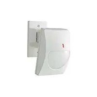
CX702 MKII - Détecteur OPTEX - Notice d'utilisation et mode d'emploi gratuit
Retrouvez gratuitement la notice de l'appareil CX702 MKII OPTEX au format PDF.

| Type de produit | Détecteur infrarouge passif (PIR) |
| Marque | Optex |
| Modèle | CX702 MKII |
| Poids | 200 g (7.0 oz) |
| Alimentation | 9,5 - 16 V CC |
| Consommation électrique (CX-702) | 8 mA (normal) / 11 mA (max) à 12 V CC |
| Consommation électrique (CX-702V) | 8 mA (normal) / 16 mA (max) à 12 V CC |
| Méthode de détection | Infrarouge passif |
| Couverture (grand angle) | 85°/large, 21 m × 21 m (70 pi × 70 pi) |
| Couverture (longue portée) | 45 m × 2,4 m (150 pi × 8 pi) |
| Zones de détection (grand angle) | 68 zones |
| Zones de détection (longue portée) | 22 zones |
| Hauteur de montage | 1,5 - 3,6 m (5 - 12 pi) |
| Sensibilité | 1,6 °C à 0,6 m/s, hauteur de montage 2,4 m (3 °F à 2 pi/s, 8 pi) |
| Vitesse détectable | 0,3 - 1,5 m/s (1 - 5 pi/s) |
| Période d'alarme | Environ 2,5 secondes |
| Sortie d'alarme | N.C. 28 V CC 0,2 A max |
| Contact anti-sabotage | N.C., s'ouvre lorsque le capot est retiré, 28 V CC 0,1 A max |
| Comptage d'impulsions | 2 ou 4 (env. 20 s) |
| Période de préchauffage | Environ 1 minute |
| Indicateur LED | Allumé en cas d'alarme (commutable) |
| Immunité aux interférences RF | Aucune alarme à 30 V/m |
| Température de fonctionnement | -20 °C à +50 °C (-4 °F à +122 °F) |
| Humidité ambiante | 95% max |
| Fonction mémoire d'alarme (CX-702V) | Oui, avec borne A.M. |
| Borne de contrôle LED à distance (CX-702V) | Borne D.L. |
| Accessoires en option | Support mural CA-1W, support plafond CA-2C |
| Homologations | CX-702 : UL 639 ; CX-702V : non évalué par UL |
FOIRE AUX QUESTIONS - CX702 MKII OPTEX
Questions des utilisateurs sur CX702 MKII OPTEX
0 question sur cet appareil. Repondez a celles que vous connaissez ou posez la votre.
Poser une nouvelle question sur cet appareil
Téléchargez la notice de votre Détecteur au format PDF gratuitement ! Retrouvez votre notice CX702 MKII - OPTEX et reprennez votre appareil électronique en main. Sur cette page sont publiés tous les documents nécessaires à l'utilisation de votre appareil CX702 MKII de la marque OPTEX.
MODE D'EMPLOI CX702 MKII OPTEX
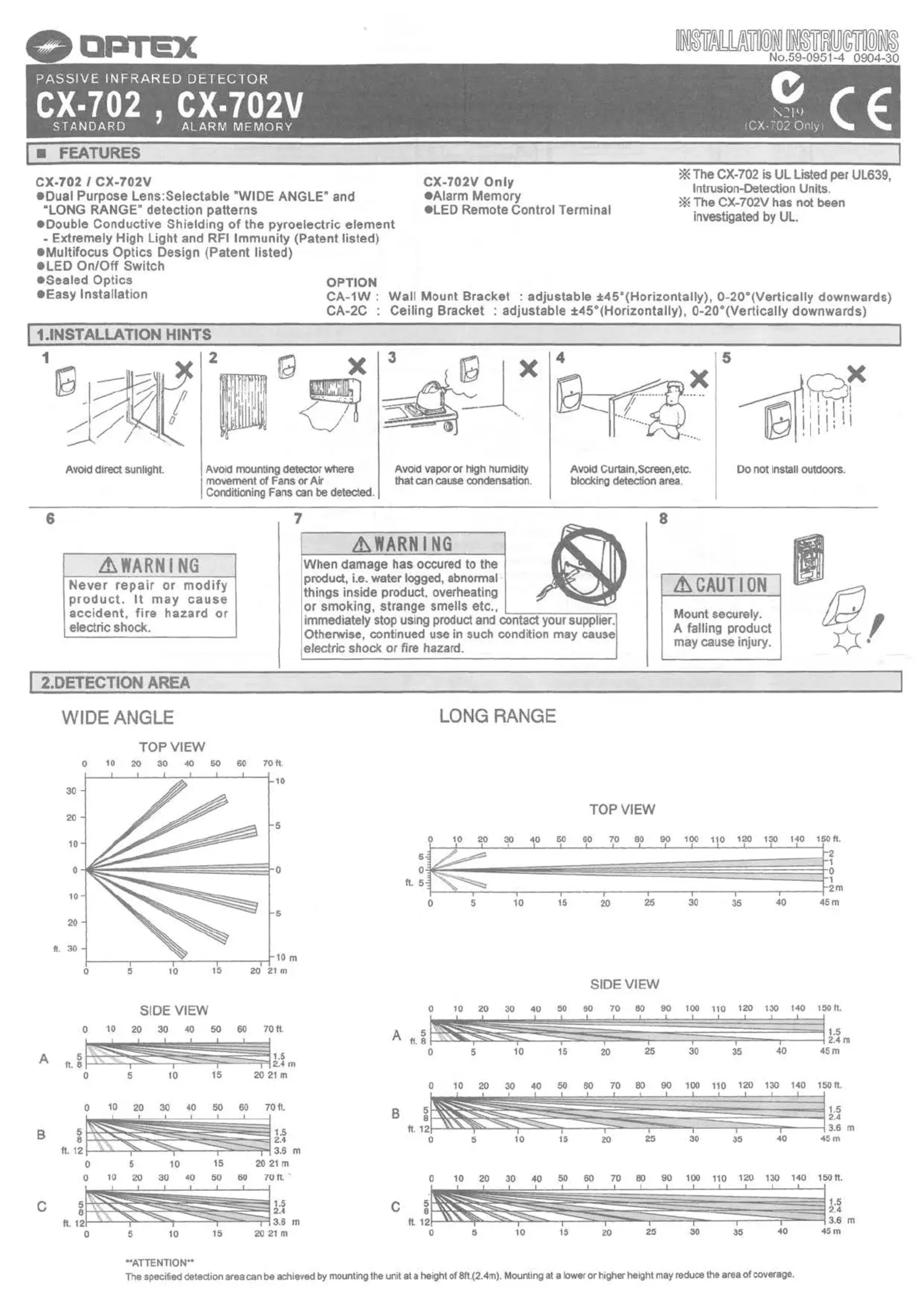
PASSIVE INFRAREDDETECTOR
CX-702 , CX-702V
STANDARD
ALARM MEMORY

219
(CX-702 Only)

FEATURES
CX-702 / CX-702V
Dual Purpose Lens: Selectable "WIDE ANGLE" and
"LONG RANGE" detection patterns
Double Conductive Shielding of the pyroelectric element
- Extremely High Light and RFI Immunity (Patent listed)
Multifocus Optics Design (Patent listed)
-LED On/Off Switch
Sealed Optics
Easy Installation
OPTION
CX-702V Only
Alarm Memory
LED Remote Control Terminal
The CX-702 is UL Listed per UL639 Intrusion-Detection Units.
The CX-702V has not been investigated by UL.
CA-1W: Wall Mount Bracket : adjustable ±45°(Horizontally), 0-20°(Vertically downwards)
CA-2C : Ceiling Bracket : adjustable ±45°(Horizontally), 0-20°(Vertically downwards)
1. INSTALLATION HINTS

↑
Avoid direct sunlight.
2
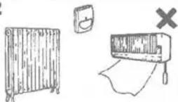
Avoid mounting detector where
movement of Fans or Air
Conditioning Fans can be detected.

3
Avoid vapor or high humidity
that can cause condensation.

4
Avoid Curtain,Screen,etc.
blocking detection area.
5
6
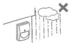
Do not install outdoors.
WARNING
Never repair or modify product. It may cause accident, fire hazard or electric shock.
7
WARNING
When damage has occurred to the product, i.e. water logged, abnormal things inside product, overheating or smoking, strange smells etc.,
immediately stop using product and contact your supplier. Otherwise, continued use in such condition may cause electric shock or fire hazard.
8
CAUTION
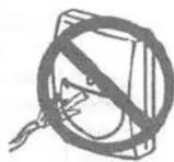
Mount securely. A falling product may cause injury


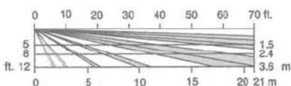
2.DETECTION AREA

WIDE ANGLE

A
B

C

LONG RANGE



4. INSTALLATION

1
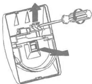
Loosen fastening screw and remove cover.

2


Lead in wires through knockouts along the wiring guide on the rear side of base. Mount base with supplied screws. When using a bracket, check matching knockout position before opening mounting holes.Wire according to Section 5.

When you remove the PCB, push down on the hook under PCB and remove it from its base. Attachment of PCB is the reverse of removal.
3
Remove the screw fixed the lens holder(CX-702V Only), open the cover's hook and then lens cover can be removed.

4

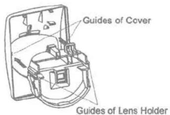
Remove lens holder carefully. Select wide angle or long range according to Section 6-2. (Note: Factory default is WIDE ANGLE.)
5
Check to confirm that the lens is in the desires position. Press down the lens holder until it clicks into place along the guide of cover. Fix the screw at the end.

6
Conduct a walktest and make adjustments (Section 7). Fit cover using fastening screw.

5.WIRING

CX702

CX-702V

Power wires should not exceed the following lengths.
| CX-702 | CX-702V | |||
| WIRE SIZE | 12V | 14V | 12V | 14V |
| AWG 22(0.33mm²) | 1700ft(520m) | 3700ft(1130m) | 1180ft(360m) | 2520ft(770m) |
| AWG 20(0.52mm²) | 2690ft(820m) | 5830ft(1780m) | 1830ft(560m) | 4000ft(1220m) |
| AWG 18(0.83mm²) | 4290ft(1310m) | 9350ft(2850m) | 2950ft(900m) | 6430ft(1960m) |
When using two or more units on one wire, the maximum length is obtained by dividing the maximum wire length listed above by the number of units used.
6.ADJUSTMENTS FOR REQUIRED AREA PATTERN
The CX-702 is designed to provide ideal detection areas for different patterns ranging from 40ft.(12m) to 70ft.(21m) Wide Angle, and 80ft.(24m) to 150ft.(45m) Long Range.
The following adjustments will provide ideal detection areas for each of these requirements.
I. DETERMINE THE AREA PATTERN
Before making adjustments, determine the pattern area, detection range mounting height.
2 SELECTING WIDE ANGLE OR LONG RANGE DETECTION
- Inverting the lens will select either the Wide Angle or Long Range detection patterns.
- Please note markings "W(Wide Angle)" and "L(Long Range)", on each side of lens.
- For Wide Angle, "W" will be on top of lens.
- For Long Range, "L" will be on top of lens.
3.VERTICAL ADJUSTMENT OF DETECTION AREA
Adjust the vertical angle according to the desired detection range and mounting height.
- Set the upper edge of the lens at either the "A", "B" or "C" position.
- The following chart illustrates the different position setting.
- Confirm the detection area by conducting a walktest.

ft.(m)
| W: WIDE ANGLE | |||||
| DISTANCE | |||||
| 40 (12) | 50 (15) | 60 (18) | 70 (21) | ||
| HEIGHT | 6 (1.8) | B | A | A | A |
| 8 (2.4) | C | C | C | C | |
| 12 (3.6) | C | C | C | C | |
| L: LONG RANGE | |||||
| DISTANCE | |||||
| 80 (24) | 100 (30) | 120 (36) | 150 (45) | ||
| HEIGHT | 6 (1.8) | B | B | A | A |
| 8 (2.4) | C | C | C | C | |
| 12 (3.6) | C | C | C | C | |
7 FUNCTIONS
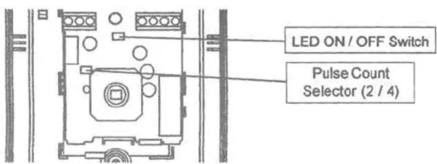
CAUTION!
Always conduct a walktest after changing the position of this switch to ensure the detector is still providing optimum coverage.
1. LEDON/OFF
Jumper Pin Switch
The Alarm LED indicator can be switched either "ON" or "OFF".
D.L. terminal (CX-702V Only)
LED can be enabled or disabled remotely from control panel by D.L. terminal.
1) Place Jumper Pin Switch in OFF position.
2)LED"ON":Connect DL terminal to common ground with detector.(0~1VDC,grounded)
LED"OFF": No Connection to the DL terminal.(OPEN or +5~16VDC)
2. PULSE COUNT
The Detection Mode can be switched to either "2" or "4" mode depending on the environmental conditions of the installation.
2: For normal applications.
4: For use in hostile areas where there may be movement of small animals or other objects such as fax machines or curtains.
When the "4" is selected, the detector's sensitivity may seem sluggish. It is therefore important to always conduct a walktest to ensure that the desired coverage is given.

ON

OFF

2

4
CAUTION!
Do not use pulse count 4 for Long Range detection.
3. ALARM MEMORY ( CX-702V Only )
Alarm Memory
This function is used to indicate if the detector was activated while the panel was armed. It will cause the red LED on the Detector to illuminate once the panel has been disarmed.
Compatible Control Panel is required for Alarm memory.
Connect A.M. terminal to Control Panel's Control Voltage Signal terminal (System Arming Status Voltage Output).
CONTROL VOLTAGE SIGNAL
| POSITIVE | NEGATIVE | |
| System Armed | OPEN or +5~16VDC | 0~1VDC(grounded) |
| System Disarmed | 0~1VDC(grounded) | OPEN or +5~16VDC |
Operation
If the unit triggered during armed period, when the system is disarmed, LED will remain lit to confirm that it reported an alarm.
Alarm Memory will operate even when LED is switched OFF.
Alarm Memory will not operate while system is disarmed.
After Alarm Memory latches, Alarm Output and LED operate normally during armed period.
Reset
Alarm Memory resets automatically when system is re-armed.
AM Jumper

POSITIVE:Leave AM Jumper as it is. NEGATIVE: Cut AM Jumper as shown.
| PROBLEM | PROBABLE CAUSE | REMEDY |
| LED does not light. | Improper power supply voltage (disconnection,low voltage). | Correct supply voltage to 9.5 - 16V DC.See Section 5. |
| Improper detection area. | See Section 2. | |
| LED switch is OFF. | Turn on the switch. | |
| Improper polarity to detector. | Switch positive and negative at terminal. | |
| LED lights even though no person within area. | Moving object within area (curtain,wall hanging,etc.). | Remove the souces from the detection area. |
| Temperature of object within area changing rapidly (heater,air conditioning,etc.). | Remove object from the detection area. | |
| LED lights but signal is not sent. | Relay contact is stuck or damaged due to overloading. | Check load of output.The unit needs repair or replacement. |
| LED continues to light | Faulty wiring. | Wire correctly. |
| Poor connection of alarm memory. | Reconnect wire. | |
| Wrong control voltage from panel. | Must be 0-1V DC(grounded) See Section 7-3. |
9.SPECIFICATIONS
| Model | CX-702 / CX-702V | |
| Detection method | Passive infrared | |
| Coverage | Wide Angle 85°/wide 70ft. × 70ft. (21m × 21m) | Long Range 150ft. × 8ft. (45m × 2.4m) |
| Detection zones | 68 zones | 22 zones |
| Mounting height | 5 - 12ft.(1.5 - 3.6m) | |
| Sensitivity | 3°F at 2ft./sec., 8ft. mounting height (1.6°C at 0.6m/sec., 2.4m mounting height) | |
| Detectable speed | 1 - 5ft. / sec. (0.3 - 1.5m/sec.) | |
| Power input | 9.5 - 16VDC | |
| Alarm period | Approx. 2.5 sec. | |
| Alarm output | N.C. 28VDC 0.2A max. | |
| Tamper switch | N.C. Opens when cover is removed. 28VDC 0.1A max. | |
| Pulse count | Approx. 20 sec. 2 or 4 | |
| Warm-up period | Approx. 1 min. | |
| LED indicator | Alarm condition | |
| RF interference | No alarm 30V/m | |
| Operating temperature | -4°F - +122°F(-20°C - +50°C) | |
| Environment humidity | 95% max. | |
| Weight | 7.0oz (200g) | |
*Specifications and design are subject to change without prior notice.
| Model | CX-702 |
| Current draw | 8mA (normal) / 11mA (max.) at 12VDC |
| Model | CX-702V |
| Current draw | 8mA(normal) / 16mA(max.) at 12VDC |
| Alarm Memory | See Section7-3. |
| D.Lterminal | See Section7-1. |


NOTE
These units are designed to detect movement of an intruder and activate an alarm control panel. Being only part of a complete alarm system, we cannot accept responsibility for any damages or other consequences resulting from an intrusion. These products conform to the EMC Directive 2004/108/EC.
OPTEX
OPTEX CO.,LTD.(JAPAN) (ISO 9001 Certified) (ISO 14001 Certified) 5-8-12 Cueto Ochoa Sogra 5,20-0301 (JAPAN) TCC: +87-77-579-8570 FAX:+81-77-579-8750 UFB http://www.ufb.co.jp/
OPTEX INCORPORATED (USA)
TEL: +1 8969-520-5770
Tech: 630266787020
URL: http://www.optep-camera.com!
OPTEX (EUROPE) LTD. (UK)
TEL: +44 16283316000
URL: http://www.optep-camera.com!
OPTEX SECURITY SP.z.o.o. (POLAND)
TEL: 140-22-988-69-05
Fax: http://www.optex.com.pl
OPTEX KOREA CO., LTD. (KOREA)
TEL: 832-2719-5971
URL: http://optexkorea.com/
OPTEX SECURITY SAS (FRANCE)
http://www.optex.fr/
IRF: http://www.optex.safecountry.fr
OPTEX (ONGQUANG) CO.,LTD. SHENZHEN OFFICE (CHINA) TEL:+86-53-92029501 UFL, http://www.optexchina.com


- FEATURES
- INSTALLATION HINTS
- WARNING
- CAUTION
- 2.DETECTION AREA
- INSTALLATION
- 5.WIRING
- 6.ADJUSTMENTS FOR REQUIRED AREA PATTERN
- DETERMINE THE AREA PATTERN
- SELECTING WIDE ANGLE OR LONG RANGE DETECTION
- 3.VERTICAL ADJUSTMENT OF DETECTION AREA
- FUNCTIONS
- CAUTION!
- LEDON/OFF
- PULSE COUNT
- ALARM MEMORY ( CX-702V Only )
- 9.SPECIFICATIONS
- NOTE
- OPTEX
Marque : OPTEX
Modèle : CX702 MKII
Catégorie : Détecteur