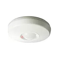
FX-360 - Détecteur OPTEX - Notice d'utilisation et mode d'emploi gratuit
Retrouvez gratuitement la notice de l'appareil FX-360 OPTEX au format PDF.


| Type de produit | Détecteur de mouvement infrarouge passif (PIR) |
| Marque | Optex |
| Modèle | FX-360 |
| Utilisation | Intérieur |
| Portée de détection | 12 mètres à 90° |
| Angle de détection | 90 degrés |
| Alimentation | 12V DC (courant continu) |
| Consommation électrique | 15 mA (max) |
| Température de fonctionnement | -10°C à +50°C |
| Dimensions (L x H x P) | 120 x 60 x 45 mm |
| Poids | 100 g |
| Sortie relais | Contact sec NF (normalement fermé) |
| Indicateur LED | Oui (rouge pour alarme) |
| Protection anti-sabotage | Contact anti-ouverture (tamper) |
| Immunité aux animaux | Jusqu'à 25 kg (réglable) |
| Entretien et nettoyage | Nettoyer la lentille avec un chiffon doux et sec. Ne pas utiliser de solvants. |
| Installation | Montage mural en intérieur, à 2 m de hauteur |
| Homologation | CE, EN 50131 Grade 2 |
FOIRE AUX QUESTIONS - FX-360 OPTEX
Questions des utilisateurs sur FX-360 OPTEX
0 question sur cet appareil. Repondez a celles que vous connaissez ou posez la votre.
Poser une nouvelle question sur cet appareil
Téléchargez la notice de votre Détecteur au format PDF gratuitement ! Retrouvez votre notice FX-360 - OPTEX et reprennez votre appareil électronique en main. Sur cette page sont publiés tous les documents nécessaires à l'utilisation de votre appareil FX-360 de la marque OPTEX.
MODE D'EMPLOI FX-360 OPTEX
IX. SPECIFICATIONS
| Model | FX-360 |
| Detection method | Passive Infrared |
| Coverage | 25 ft - 40 ft / ( 8 m - 12 m) |
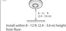
| Height: 8 ft - 12 ft / (2.4 m - 3.6 m) | |
| Detection zones | 62 zones |
| Sensitivity | 3° F (1.6° C) at 2 ft/sec. (0.6 m/sec.) |
| Detectable speed | 1 - 5 ft/sec. (0.3 - 1.5 m/sec.) |
| LED indicator | LED is blinking during warm-up period. |
| Alarm indicator optional | |
| Alarm period | 2.0 ±0.5 sec. |
| Alarm output | N. C. 28 VDC 0.2 A max. |
| Tamper switch | N. C. 30 VDC 0.1 A max, Opens when cover removed. |
| Pulse Count | 20 ±5 sec. 2 or 4 |
| Warm up period | Approx 30 sec. (LED blinks.) |
| Power input | 9.5 - 18 VDC |
| Current draw | 17 mA at 12 V DC / (normal) |
| 18 mA at 12 V DC / (max.) | |
| Weight | 4.9 oz (140 g) |
| Operating temperature | -4° F - +122° F (-20° C - +50° C) |
| Environmental humidity | 95% max. |
| RFI interference | No Alarm 20V / m |
NOTE
This unit is designed to detect an intruder and activate an alarm control panel. Being only a part of a complete system, we cannot accept responsibility for any damages or other consequences resulting from an intrusion.

Dimensions
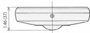
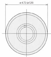
Mounting Position

*Specifications and design are subject to change without prior notice.

OPTEX
OPTEX CO., LTD. (JAPAN)
www.opte
OPTEX SECURITY SAS (France)
OPTEX KOREA CO.,LTD. (Korea)
OPTEX INC./AMERICAS HQ (U.S.)
OPTEX (EUROPE) LTD./EMEA HQ (U.K.)
OPTEX SECURITY Sp.z o.o. (Poland)
OPTEX (DONGGUAN) CO.,LTD.
OPTEX SECURITY B.V.
(The Netherlands)
PVT., LTD. (India)
OPTEX (Thailand) CO., LTD. (Thailand)
www.optex-europe.com/nl
www.optexpinnacle.com
Copyright (C) 1992-2024 OPTEX CO.,LTD.

OPTEX
PASSIVE INFRARED DETECTOR
FX-360
FEATURES
○ Ceiling Mount Type 360° PIR Detector.
○ Selectable pulse count 2 or 4.
○ LED ON/OFF remotely from the control panel or the detector.
I. INSTALLATION HINTS
The nix sign indicates prohibition.
①

Avoid direct sunlight.


COMPLIANCE
○Ull Listed
- EN50131-2-2 Security Grade 2. Environmental Class II
tested and certificated by Kiwa B.V.
○ PD6662:2017
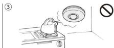
Avoid vapor or high humidity that can cause condensation.
⑥
II. DETECTION AREA
radar
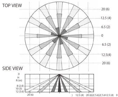
| Angle | Top View (ft m) | Side View (ft m) | |---|---|---| | 0 | 20 (6) | 0 | | 30 | 12.5 (4) | 8 (2.4) | | 60 | 6.5 (2) | 10 (3) | | 90 | 6.5 (2) | 12 (3.6) | | 120 | 12.5 (4) | 20 (6) | | 150 | 20 (6) | 12.5 (4) | | 180 | 12.5 (4) | 12.5 (4) | | 210 | 6.5 (2) | 5.6 (2) | | 240 | 6.5 (2) | 5.6 (2) | | 270 | 12.5 (4) | 5.6 (2) | | 300 | 20 (6) | 0 |D ft (m)
MAX. Detection AREA
| Installation Height ft (m) | 8(2.4) | 10(3) | 12(3.6) |
| Detection Area (Diameter) ft (m) | 25(8) | 32(10) | 40(12) |

IV. INSTALLATION METHOD

Loosen fastening screw and remove cover.
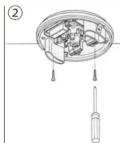
Mount the unit and wire according to Section V.

Replace the cover and supply power to unit. When LED stops blinking, the warm-up period is complete (Apx. 30 sec.)
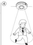
Conduct a Walk Test.
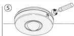
Select pulse count according to your coverage needs and environmental condition Fasten cover with fastening screw.
V. WIRING

Power wires should not exceed the following lengths.
| FX-360 | ||
| WIRE SIZE | 12V | 14V |
| AWG22 (0.33mm ^2 ) | 1 070' (320 m) | 2 140' ( 650 m) |
| AWG20 (0.52mm ^2 ) | 1 700' (510 m) | 3 400' (1 020 m) |
| AWG18 (0.83mm ^2 ) | 2 700' (820 m) | 5 300' (1 600 m) |
- When using two or more units on one wire, the maximum length is obtained by dividing the above length by the number of units used.
- UL requires FX-360 to be connected to a UL listed power supply capable of providing a nominal input of 12 V DC (9.5 - 18 V DC) 18 mA (max.) [FX-360], and battery standby time of 4 hours.
VI. LED ON-OFFIII. DESCRIPTION AND OPERATION
○ Use Jumper Pin Switch for LED "ON" "OFF" as shown.
Use D. L. terminal to turn LED ON-OFF from control panel remotely.
i) Place Jumper Pin Switch in OFF position.
ii) LED ON: Connect D. L. terminal to common ground with detector LED OFF: No connection to D.L. terminal.
JUMPER PIN SWITCH
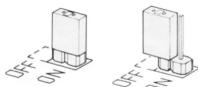
LED ON

LED OFF
| Remotely | On the Detector | |
| LED Enabled | Connect DL terminal to common ground (with detector). | Connect (-) terminal of power input to DL terminal. |
| LED Disabled | No ground to DL terminal (open circuit). | No connection to DL terminal (open circuit). |
VII. PULSE COUNT
Select 2 for regular applications. For unstable environments, select 4. Shift Pin Swich as shown.
* NOTE: ON PULSE COUNT DURING WALK TEST
Once initial movement is detected during the walk test, subsequent movements that are within the delayed timer period (approx. 20 seconds) will override the pulse count setting and cause an instant trigger. This feature assures location of each detection zone and accelerates the confirmation of pattern coverage in the walk test.

* Certified to EN, SBSC and INCERT when set to "2 PULSE"
VIII. TROUBLE SHOOTING AND MAINTENANCE
| PROBLEM | PROBABLE CAUSE | REMEDY |
| LED does not light. | Incorrect power supply voltage.(disconnection, low voltage) | Correct supply voltage ± 9.5 - 18V DC. |
| Incorrect detection area. | See Section II. | |
| Incorrect polarity to detector. | Switch positive and negative at terminal. | |
| LED switch is OFF | Turn on the Switch. See Section VI. | |
| LED lights even though no person within the detection area. | Moving object within area. (curtain, wall hanging, etc.) | Remove object from detection area. |
| Rapid temperature changes within area.(heater, air-conditioner, etc.) | Remove the sources from detection area. | |
| LED lights but signal is not sent. | Relay contact is stuck or damaged due to overloading. | Check load of output.The unit needs repair or replacement. |
| Faulty Wiring | Wire correctly. |
* Conduct a walk test at least once per year.



Marque : OPTEX
Modèle : FX-360
Catégorie : Détecteur