HB875G5B1 - Plaque de cuisson SIEMENS - Notice d'utilisation et mode d'emploi gratuit
Retrouvez gratuitement la notice de l'appareil HB875G5B1 SIEMENS au format PDF.

| Type d'appareil | Four encastrable |
| Capacité | 71 litres |
| Classe énergétique | A+ |
| Modes de cuisson | Chaleur tournante, grill, cuisson traditionnelle |
| Température maximale | 275°C |
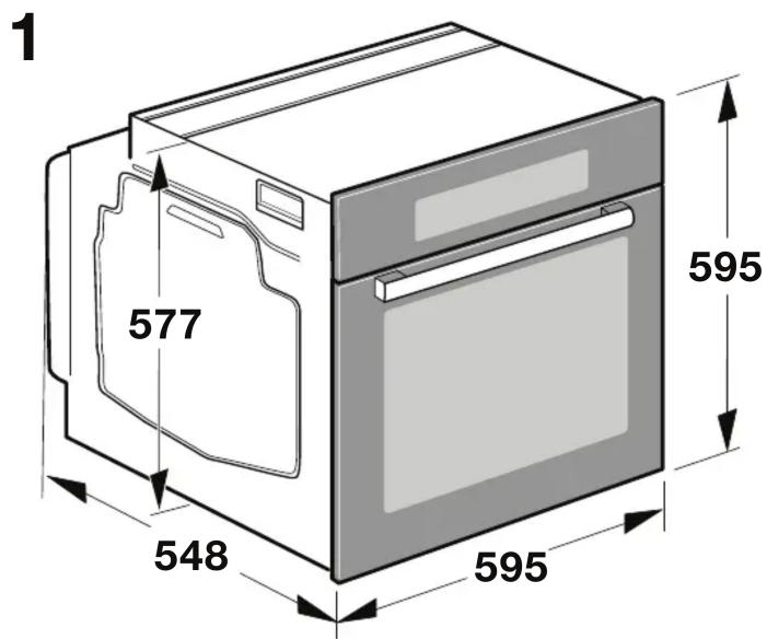
| Dimensions (L x H x P) | 595 x 595 x 548 mm |
| Poids | 36 kg |
| Type de nettoyage | Nettoyage par catalyse |
| Écran | Affichage numérique |
| Fonctionnalités supplémentaires | Programmes automatiques, minuterie |
| Consommation électrique | 0.87 kWh (chaleur statique), 0.69 kWh (chaleur tournante) |
| Sécurité | Verrouillage de sécurité, porte froide |
| Garantie | 2 ans |
FOIRE AUX QUESTIONS - HB875G5B1 SIEMENS
Questions des utilisateurs sur HB875G5B1 SIEMENS
0 question sur cet appareil. Repondez a celles que vous connaissez ou posez la votre.
Poser une nouvelle question sur cet appareil
Téléchargez la notice de votre Plaque de cuisson au format PDF gratuitement ! Retrouvez votre notice HB875G5B1 - SIEMENS et reprennez votre appareil électronique en main. Sur cette page sont publiés tous les documents nécessaires à l'utilisation de votre appareil HB875G5B1 de la marque SIEMENS.
MODE D'EMPLOI HB875G5B1 SIEMENS
en
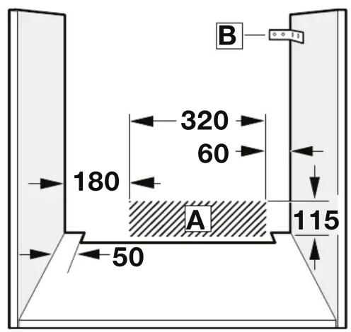
Important information - Fig. 1
The safe operation of this appliance can only be guaranteed if it has been installed to a professional standard in accordance with these installation instructions. The installer shall be liable for damages incurred as a result of incorrect installation.
Check the appliance for damage after unpacking it. Do not connect the appliance if it has been damaged in transit.
Before starting up the appliance, remove any packaging material and adhesive film from the cooking compartment and the door.
Fitted units must be heat-resistant up to 90^ , and adjacent unit fronts up to 70^ .
- Do not install the appliance behind a decorative panel. There is a risk of overheating.
Any cut-outs that need to be made in the units should be made before the appliance is installed. Remove any shavings as they may prevent the electrical components from working properly.
Wear protective gloves so that you do not cut yourself. Parts that are accessible during installation may have sharp edges.
For appliances that have a hinged switch panel, make sure that the switch panel does not hit adjacent kitchen units when you open it.
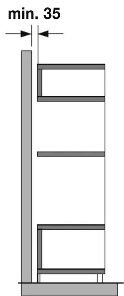
The power socket for the appliance must either be located in the hatched area A or outside of the area where the appliance is installed.
- Secure any unsecured units to the wall using a standard bracket B.
The dimensions in the figures are in mm.
Wearers of electronic implants!
The appliance may contain permanent magnets which may affect electronic implants, e.g. heart pacemakers or insulin pumps. Therefore, during installation, wearers of electronic implants must maintain a minimum distance of 10cm from the appliance.
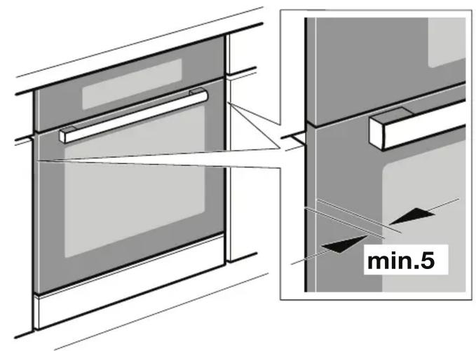
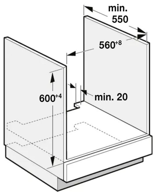
Appliance under worktop - Fig. 2
To ventilate the appliance, the intermediate floor must have a ventilation cut-out.
Secure the worktop to the fitted units.
If the appliance is installed under a hob, the following minimum dimensions must be adhered to (including substructure, if applicable):
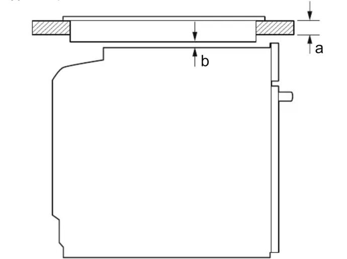
| Hob type | a Fixed | a Flush with sur- rounding surfaces | b |
| Induction hob | 37 mm | 38 mm | 5 mm |
| Full-surface induction hob | 43 mm | 48 mm | 5 mm |
| Gas hob | 32 mm | 42 mm | 5 mm |
| Electric hob | 22 mm | 24 mm | 2 mm |
The minimum worktop thickness a results from the minimum required dimension b.
Observe the installation instructions for the hob.
Appliance in a tall unit - Fig. 3
To ventilate the appliance, the intermediate floors must have a ventilation cut-out.
If the tall unit has another back panel in addition to the element back panels, this must be removed.
Only fit the appliance up to a height which allows accessories to be easily removed.
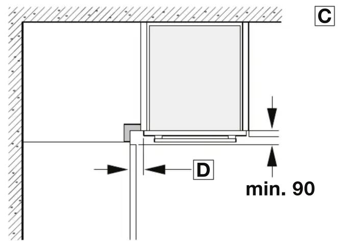
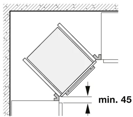
Corner installation - Fig. 4
To ensure that the appliance door can be opened in a corner installation, take account of dimension C. Dimension D is dependent on the thickness of the unit front under the handle.
Connecting the appliance
The appliance corresponds to protection class 1 and must only be operated with a protective earth connection.
The fuse protection must correspond to the power rating specified on the appliance's rating plate and to local regulations.
The appliance must be disconnected from the power supply whenever installation work is being carried out.
The appliance must only be connected with the power cable provided. Connect the power cable to the back of the appliance (listen for the click).
A 3 m power cable can be obtained from the after-sales service. The power cable must only be replaced with a cable from the original manufacturer, which can be obtained from the after-sales service.
When the appliance is installed, protection must be provided against accidental contact in the future.
Power cable with a plug with earthing contact
The appliance must only be connected to a properly installed protective contact socket.
If the plug is no longer accessible following installation, an all-pole isolating switch must be present on the installation side with a contact gap of at least 3mm
Power cable without a three-pin earthed plug
The appliance must only be connected by a licensed professional.
The installation must have an all-pole isolating switch with a contact gap of at least 3mm . Identify the live and neutral conductors in the mains socket. The appliance may be damaged if it is not connected correctly.
Only connect the hob as shown in the connection diagram. See the rating plate for the voltage. Connect the wires of the mains power cable according to the colour coding: Green/yellow = PE conductor < , blue = neutral conductor, brown = live (external conductor).
Only in Sweden, Finland and Norway
The appliance can also be connected using the plug provided which has an earthing contact system. This must still be accessible after installation. If this is not the case, an all-pole isolating switch must be used on the installation side with a contact gap of at least 3mm .
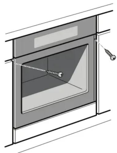
Securing the appliance - Fig. 5
-
Fully insert the appliance and centre it.
-
Screw the appliance into place.
The gap between the worktop and appliance must not be sealed by additional strips.
Thermal insulation strips must not be fitted to the side panels of the surround unit.
Removal
- Disconnect the appliance from the power supply.
- Undo the securing screws.
- Lift the appliance slightly and then pull it out completely.
b 1aalaa aalaa jdall jae yaa a Jaae baw claw d
gallj yalil alalill gji
3J- aUle d g jLjll
a aaaan aaan an aan anan anan anan anan anan anan anan anan anan anan anan anan anan anan anan anan anan anan anan anan anan anan anan anan anan anan anan anan anan anan anan anan anan anan anan anan anan anan anan anan anan anan anan
aalil 1ylll aal yla 1y lgl 1e alaaall aalld
aIgsss sll lssse gles
4J-+
C 1
aall 1dawdwl g dawgicdd
jL
aLaaagjg jy 1 aalll gao j
jglg 1s sgs yghy jy hgyd ydy dyl lalbdo yda laa a
all
J 1
y 11 11 y 11 y 11 y 11 y 11 y 11
(gss)
- 与 S1 相似 S2 , S3 , S4 , S5 , S6 , S7 , S8 , S9 , S10 , S11 , S12 , S13 , S14 ,
gJyI 1
1000000000000000000000000000000000000000
jusy
J 1
y 1 1 1 1 1 1 1 1 1 1 1 1 1 1 1 1 1 1 1 1 1 1 1 1 1 1 1 1 1 1 1 1
Jusu
aaiiaieiiee iieae
3 3 3 3 3 3 3 3 3 3 3 3 3 3 3 3 3 3 3 3 3 3 3 3 3 3 3 3 3 3 3 3 3 3 3 3 3 3 3 3 3 3 3 3 3 3 3 3 3 3 3
(
gul gulie g uall
Jg 3 j
5 jL -jLJI
aJg j 1
a. a. 2
LbIaIbIaIbIaIbIaIbIaIbIaIbIaIbIaIbIaIbIaIbIaIbIaIbIaIbIaIbIaIbIaIbIaIbIaIbIaIbIaIbIaIbIaIbIaIbIaIbIaIbIa
a a a a a a a a a a a a a a a a a a a a
J 1
jI 2
Jolll 111 111 111 111 111 111 111 1.3
a a a a a a a a a a a a a a a a a a a a a a a a a a
J 1
J 1
a 1
Jillie Jace je jzjli jzjki jll
J 1
a 90 g a
0^ 70 0y_0( 1 - x)
Aaiaaa aaiiie aiee iieae
i j 100000000000000000000000000000000000000000000
J 1 J 1
Lg 1
aJgall jgs
pIbIjpe joo 5i, aJiaioe cuiilao oJyol gie laaiillll
aaiiie aaiiie aaiiaaiiaaiiaaiiaaiiaai
J 1 A aallll al lol jllllllllllll
jL 11 jL jL jll a b
B 1
a 1
aeggaaaggckll aaboojogolalall
a jgjS11 1 a bll 8jg j 1 1 1 1 1 1 1 1 1 1 1 1 1 1 1 1 1 1 1 1 1
a 1
golulj g aegg jao g jgiill lal y jy jy jolal all jolil
10 10 10
2Jsi-Jaellcbw cai jglal
a a a a a a a a a a a a a a a a a a
a
aal) aalllll lalwlll d jy jy jy jy jy jy jy jy jy jy jy jy jy jy jy jy jy jy jy jy jy jy jy
:J 1
b
a
a
中
| po 5 | po 38 | po 37 | العربية |
| po 5 | po 48 | po 43 | العربية |
| po 5 | po 42 | po 32 | العربية |
| po 2 | po 24 | po 22 | العربية |
4
5
2

3