
WHTR42200A - Contrôleur HAGER - Notice d'utilisation et mode d'emploi gratuit
Retrouvez gratuitement la notice de l'appareil WHTR42200A HAGER au format PDF.

| Marque | Hager |
| Modèle | WHTR42200A |
| Type de produit | Contrôleur KNX |
| Dimensions (L x H x P) | 45 x 45 x 17 mm |
| Poids | 0,05 kg (estimation) |
| Alimentation | Bus KNX (10,70 mA) |
| Support KNX | TP1 |
| Fonctions principales | Commutation, variation, commande de stores, appels de scènes, émetteur de valeurs, contrôle des modes de chauffage |
| Nombre de boutons | Variable (selon configuration) |
| Récepteur IR | 12 canaux IR intégrés |
| LED de statut | Programmable par bouton (couleur, fonction) |
| Mode de fonctionnement | Simple surface ou double surface |
| Installation | En boîte d'encastrement (profondeur 45 mm) ou sur rail |
| Température de fonctionnement | -5 °C à +45 °C |
| Température de stockage | -20 °C à +70 °C |
| Indice de protection | IP20 |
| Normes | EN 60569-2-1, EN 60569-1 |
| Entretien et nettoyage | Nettoyer avec un chiffon doux et sec. Ne pas utiliser de produits abrasifs. |
| Sécurité | Installation par un électricien qualifié. Respecter les normes de sécurité. Débrancher avant intervention. |
| Pièces détachées et réparabilité | Pas de pièces détachées spécifiques. Contacter le SAV Hager. |
| Informations générales | Marquage CE, utilisation dans toute l'Europe (et Suisse). |
FOIRE AUX QUESTIONS - WHTR42200A HAGER
Questions des utilisateurs sur WHTR42200A HAGER
0 question sur cet appareil. Repondez a celles que vous connaissez ou posez la votre.
Poser une nouvelle question sur cet appareil
Téléchargez la notice de votre Contrôleur au format PDF gratuitement ! Retrouvez votre notice WHTR42200A - HAGER et reprennez votre appareil électronique en main. Sur cette page sont publiés tous les documents nécessaires à l'utilisation de votre appareil WHTR42200A de la marque HAGER.
MODE D'EMPLOI WHTR42200A HAGER
Safety instructions
Electrical equipment may only be installed and assembled by a qualified electrician. Always follow the relevant accident prevention regulations of the country.
Failure to comply with these installation instructions may result in damage to the device, fi - ro or other hazards.
When installing and routing cables, always use the same type of cable and standards for SELV electrical circuit.
These instructions are an integral component of the product and must be retained by the end user.
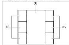
Design and layout of the device
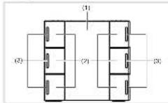
Figure 1: Front view push-button # buttons
Figure 2: Front view camera button 6 clicks with LED and backlighting, with an without IR receiver
(1) Labeling field insert with backlighting
(2) Bullets (number dependent on the variable)
(3) Status LEDs
Function
System information
This device is a product of the KNX system and corresponds to the KNX guidelines. Detailed specialized knowledge obtained from KNX training courses
is required for understanding. The planning, installation and operation of the car can use this help of KNX-smart software.
system link commissioning
The function of the device is software-dependent. The software is to be taken from the product database. You can find the latest version of the product database, technical descriptions as well as conversion and additional support programmes on our website.
easy link commissioning
The function of the device is configuration-dependent. The config generation can also be done using devices developed specially for simple selling and commissioning.
The type of configuration is only possible with devices of the easy link system, easy link stands for easy, visually supported comfallsorbering. Functional configuration is also possible to be in the six outputs by means of a service module:
Correct use
- Operation of loads, e.g. light on/off, dimming,
-
Blind up/down, saving and opening light scenes,
-
Installation into wall box of 45mm depth
- Mounting in trunking
Product characteristics push-button
Commissioning and programming in S-mases and E-mages
- Push-button functions: switchingdlimming,bind control, value transmitter, scene call-up, specifcation of the healing operating mode, priory, allocating switch and converter function
Integrated bus application unit
Lahling field
Additional product characteristics IR push
Auto with LED
Function and colour of the status LEDs configurable for this device.
- Labeling field can be illuminated
Additional product characteristics IR pushbutton with LED
One status LED per pushbutton
-
Function and colour of the status LEDs compatible for the device
-
IR interface with 12 IR channels
- Labelling field can be illuminated
Operation
The functions of the buttons, their operation and the activation of the loads can be adjusted individually for each device.
There are two operating modes:
- Singre-surface operation:
Switching lighting on/off or dimming brighter / darker is carried out alternately by repeated pressing of the button.
TWO SURFACE OPERATION:
Two superimposed push-bolons form a function pair. For example, pricking the top surface switches lighting switches it brighter, pressing the bottom surface switches it off.
Operating a function or load
Loads, such as lighting, birds, etc., are operated using the push buttons, which are dependent on the device programming.
The underlying function is executed
The actuation pulse lasts for the duration of the actuation. Depending on the function, short and long pulses can trigger different actions, e.g. switching or turning.
Function infrared receiver
The infrared devices are B Iled with a 12 channel IR receiver. They can be controlled on operated via a Telis IR remote control. The buttons of the IR receiver are located in the central control panel with the conventional local push-bation functions.
Information for electricians
Installation and electrical connection
DANGER!
Touching live parts in the installation environment can result in an electric shock!
An electric shock can be lethal!
Disconnect the connecting cables from the roof to the ceiling, cover all live parts in the area!
Connecting and installing the device (figure 3) Installation into wall box
- Mount a xing plate (ii) to a wall box in the correct position: NOLEOBENTOP
ount the device vertically only.
For horizontal mounting the device needs separate accessories (see Accessories).
Press cover plate (5) with front frame (4) onto flinging ring (5) until fastening cleve (3) smeps into piece.
Attach push-button front (2) on the f1ush-mounted insert (3).
Circuit bus connection cable to device (3)
- Open the device (1) into the vehicle (2)
BessnHng
Disconnep bus lines from device (3).
Press cover plate (5) with front frame (4) onto fixing ring (6) until fastening cleves (3) snaps into place.
Attach push-button front [2] on the first mounted insert [3].
Circuit bus connection cable to device [3].
Snap the device (3) into the fixing plate (6).
Dismantling
Remove device (3).
DisconnecBus line from device (3)
Commissioning
system link - Loading the physical address and application software
The physica address is only ever assigned to the system. The physical device can ever be in programming mode.
If available, release the labeling file instead with bank cover (1) using the programming button
(7)
Switch on bus voltage
Free programing section:
The programming LED light up.
bus voltages is present
Load the physical address into the device.
The programming LED [6] goes out
Load application software Note down the physi
c) addres on the Ianelling h ed.
The loading of non-compatible application software is indicated by the dashed line in Table 1.
(3)
- Rassatch labelling field insert with slank cover (1).
easy link
Information on the system conforl generation can be taken from the extensive description of the service and its operation.
Appendix
Technical data
KNX medium TP 1
Com gurion Prog system Ink, Easy Ink
Current consumption KAY 10.70 m3
Consignoring marie KNX - bus repurching terminal
Dimensions/24xHxD 45x45x17mm
Degree of protection IP 20
Prrrnnnne
Operating temperature -5 +45°C
Storage transport temperature -20 +70 C
Standards EN 60569-2-1, EN 60569-1
Troubleshooting
#
Bul operations is not possible.
Check bus connection terminal
P01
Check bus voltage by briefy pressing the
programming button (7), red programming (8)
All status LEDs flashing
Cause: The loaded application programme and evaluation metrics are not compatible.
Install area installation procedure or manual
suitable application module.
Accessories
Bus connecting terminals TG08
Accessories horizontal mounting
Fixing ring electronic process 1N1409825
Exrcf frame WH262130xZ
Correct Disposal of this product: Moralis Electrical & Electronic Eq.
A
Applicable in the European Union and other European countries with separate collection systems.
To make abstract on the product in the formulae, one must find. The method may be described with the formulae made at the end of the formulae. For example, if the product is a product of two or more health care professionals from an uncontrolled state, object attribute uses this product. In other words, it is a function of the health care professionals' expectations. The reasonable use of such instruments remains.
Considered cases around conducted P_c are the same as in Fig. 1, except that the first case is not considered and how they can take this device for environmentally safe use.
The mean values of the three parameters are presented in Table 2. The results show that the average value of the mean difference between the two groups is 0.15 .
Usable in all Europe (and in Switzerland).
k cover and labelling field insert for push-bution and push-bution
ED (not within scope of delivery)
e
table with sales (not within scope of reference)
(1) (not Included)
plate with attachment ring (not within scope of delivery)
Figure 3: Assembly of the device


- Safety instructions
- Function
- System information
- system link commissioning
- easy link commissioning
- Correct use
- Product characteristics push-button
- Additional product characteristics IR push
- Additional product characteristics IR pushbutton with LED
- - Labelling field can be illuminated
- Operation
- - Singre-surface operation:
- TWO SURFACE OPERATION:
- Operating a function or load
- Function infrared receiver
- Information for electricians
- Installation and electrical connection
- DANGER!
- BessnHng
- Commissioning
- easy link
- Appendix
- Technical data
- Troubleshooting
- #
- Accessories
- Accessories horizontal mounting
Marque : HAGER
Modèle : WHTR42200A
Catégorie : Contrôleur