WMI16AAA1 - Lave-linge SMEG - Notice d'utilisation et mode d'emploi gratuit
Retrouvez gratuitement la notice de l'appareil WMI16AAA1 SMEG au format PDF.
| Caractéristiques | Détails |
|---|---|
| Type de produit | Machine à laver intégrable |
| Capacité de lavage | 7 kg |
| Vitesse d'essorage | 1200 tours/minute |
| Classe énergétique | A+++ |
| Programmes de lavage | Plusieurs programmes incluant coton, synthétique, délicat, rapide |
| Dimensions (HxLxP) | 82 cm x 60 cm x 55 cm |
| Poids | 70 kg |
| Niveau sonore | 54 dB (lavage), 76 dB (essorage) |
| Consommation d'eau | 44 L par cycle |
| Système de sécurité | Protection contre les débordements, verrouillage de sécurité |
| Entretien | Filtres à nettoyer régulièrement, tambour à entretenir |
| Garantie | 2 ans |
FOIRE AUX QUESTIONS - WMI16AAA1 SMEG
Questions des utilisateurs sur WMI16AAA1 SMEG
0 question sur cet appareil. Repondez a celles que vous connaissez ou posez la votre.
Poser une nouvelle question sur cet appareil
Téléchargez la notice de votre Lave-linge au format PDF gratuitement ! Retrouvez votre notice WMI16AAA1 - SMEG et reprennez votre appareil électronique en main. Sur cette page sont publiés tous les documents nécessaires à l'utilisation de votre appareil WMI16AAA1 de la marque SMEG.
MODE D'EMPLOI WMI16AAA1 SMEG
ISTRUZIONI DI MONTAGGIO DELLE LAVATRICI INTEGRABILI
IT
ASSEMBLY INSTRUCTIONS FOR BUILT-IN WASHING MACHINES
EN
MONTAGEANLEITUNG FÜR EINBAUBAREWASCHMASCHINEN
DE
INSTRUCTIONS DE MONTAGE DES LAVE-LINGE INTEGRABLES
FR
INSTRUCCIONES DE INSTALLACION DE LAS LAVADORAS INTEGRABLES
ES
INSTRUÇÉS DE MONTAGEM DAS MAQUINAS DE LAVAR ROUPA INTEGRÁVEIS
PT
MONTAGEINSTRUCTIES VAN INTEGREERBARE WASMACHINES
NL
MONTERINGSANVISNING FOR INTEGRERBARE VASKEMASKINER
DK
MONTERINGSANVISNINGAR FÖR INBYGGNADSBARA TVÄTTMASKINER
SE
ANKASTREÇAMASIRMAKINELERİ
ICIN MONTAJ TALIMATLARI
TR
ASSEMBLY INSTRUCTIONS FOR BUILT-IN WASHING MACHINES
IMPORTANT - This machine complies with current safety regulations governing electrical appliances and, to ensure user safety, it must be installed by a qualified technician as required by current legislation
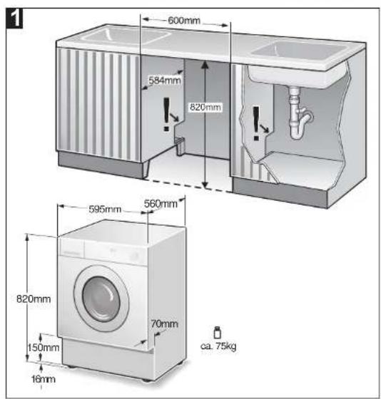
Size of cabinet The minimum dimensions of the cabinet are: height 820 mm, width 600 mm, depth 584 mm (fig. 1).
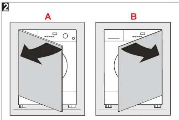
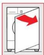
Applying the The panel may be attached to the left- or right-hand side of the panel washing machine (fig. 2)
The machine is supplied fitted for a left-hand side panel attachment as the right-hand side is fitted with the push-pull lock (upper part) and the rubber pad (lower part).
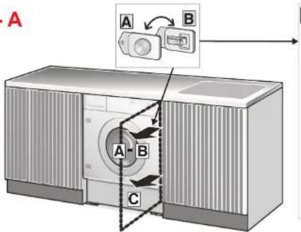
Should you wish to use the magnetic lock instead of the push-pull lock, remove the push-pull lock support and fit the supplied magnetic lock support.
Important! Before fitting the panel (removing all the hinge and locking elements from the front) make sure the washing machine is totally disconnected from the mains power supply.
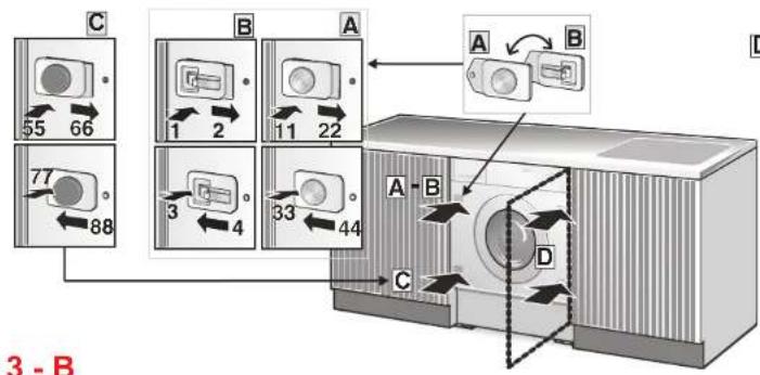
Warning - To fix the panel on the right-hand side (direction of opening opposite to that of the door) dismount the push-pull lock (or the magnet lock) from the front of the machine and the rubber pad (fig. 3-A) and fit them on the opposite side (fig. 3-B).
All the elements applied to the front of the washing machine must be remounted correctly (no holes must remain open) in order to make it impossible to touch live components inside the machine.
Our company declines all liability for failure to observe the above safety requirement.
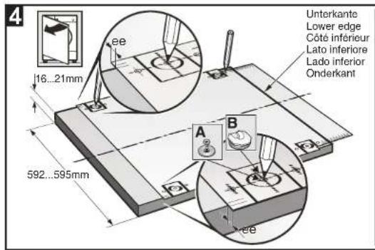
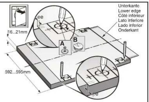
Using the tem- 1) Measure the height of the kitchen baseboard: the height of plate the wooden panel is obtained by first establishing the height of the kitchen baseboard.
E.g.: for a 100mm high baseboard, the maximum height of the panel is 720~mm . If the height of the baseboard must be increased, the height of the wooden panel must be reduced.
| Place the template of the inner side of the panel and match the height of the baseboard with the lower edge of the panel (fig. 4) using the graduated scale. Make sure the template is horizontally centred with reference to the vertical lines marked at the ends. After placing the template in the correct position, trace the positions of the following holes, pushing in with the tip of your pencil: • holes for the hinges and hinge screws (fig. 4) • holes for fixing the metal plate (if the magnetic lock is used), or the hook for the push-pull lock (fig. 4, A-B) | |
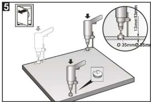
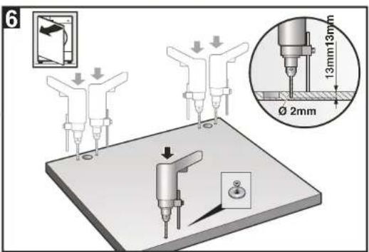
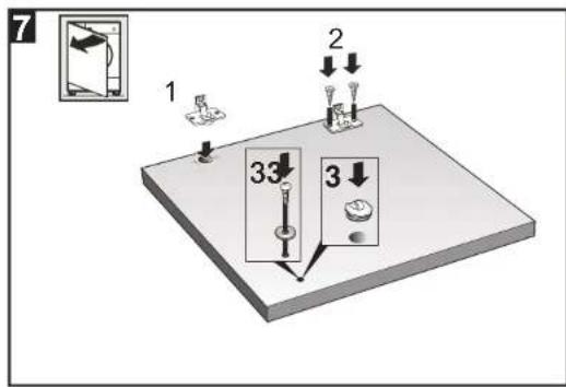
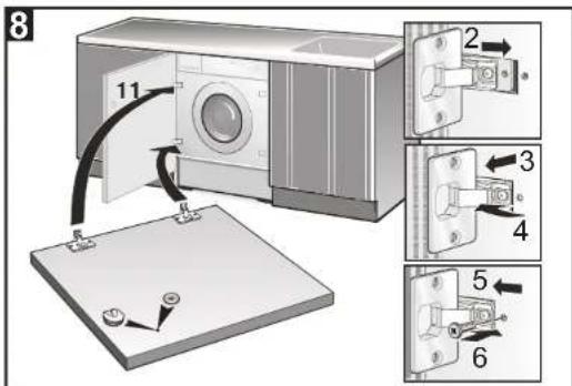
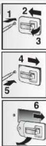
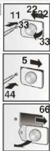
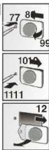
| Applying the panel elements and fixing the panel | 1) Drill the holes for the hinges (fig. 5), the hook for the push-pull lock (fig. 5), or the metal plate if you decide to use the magnetic lock (fig. 6), and the holes for fixing the hinges (fig. 6). 2) The 13 mm depth of the 2 mm holes, for fixing the hinges and a metal plate for the magnet lock, only applies to the solid wood panel. For the chipboard panel, simply drill the upper coating – fig. 6. 3) Screw the two hinges to the panel (fig. 7) 4) Mount the hook for the push-pull lock or the metal plate for the magnet lock on the side opposite the hinges (fig. 7). 5) Fix the panel to the washing machine following the instructions shown in fig. 8. |
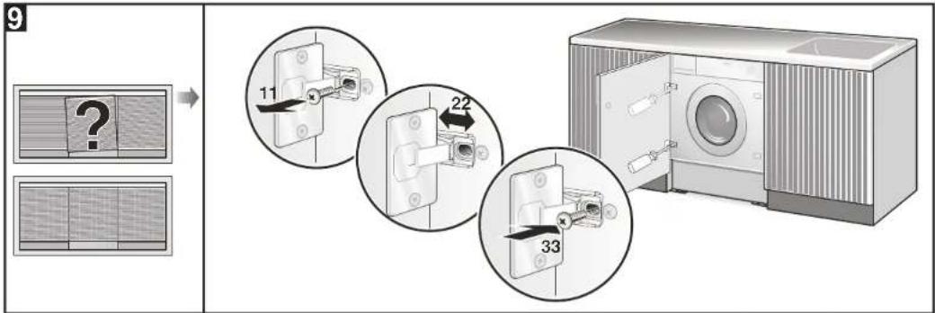
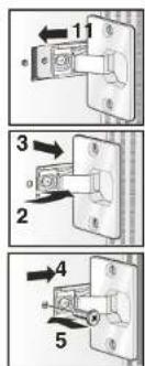
| Adjusting the hinges | If, after applying the panel to the washing machine, it is slightly inclined or off-centre with respect to the front of the machine, correct its position by adjusting the mobile part of the hinges (fig. 9). |
| Positioning the washing machine in the cabinet | Position the washing machine in the cabinet and, if necessary, adjust the feet to level it and lock them with the relative locknut. To prevent the vibrations generated by the washing machine from being transmitted to the cabinet, make sure the sides and top do not touch the cabinet. There must be a gap of at least 2 mm. The back of the machine must also remain detached from the rear panel. If the cabinet is 870 mm high, the washing machine heightening kit on sale from the Spare Parts Service, must be used. To comply with safety legislation, any gaps between the floor and the bottom of the baseplate and between the floor and the sides of the machine when it is positioned at the end of a line of furniture must be completely closed. The cover must be installed in such a way as to make it impossible to touch live components and a tool must be |
required to remove it.
Our company declines all liability for failure to observe the above safety requirement.
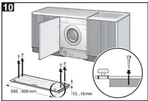
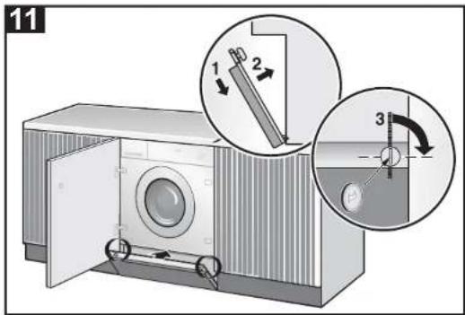
Applying the baseboard
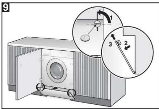
It must be possible to remove the continuous kitchen baseboard to allow the drain pump to be cleaned if necessary.
In some cases, the baseboard is not continuous but limited to the width of the washing machine. In this case, the kitchen baseboard can be fixed to the washing machine baseboard with 4 screws, respecting the 4 reference marks (see fig. 9-10-11).
When applying the kitchen baseboard, the washing machine baseboard may not be removed or adapted as, for reasons of safety, it must remain as it is, in one piece and fixed to the washing machine.
3
3-A
A
B
C
D