Bouchon étanchéité pour connecteur étanche mâle - Bouchon étanchéité HOYMILES - Notice d'utilisation et mode d'emploi gratuit
Retrouvez gratuitement la notice de l'appareil Bouchon étanchéité pour connecteur étanche mâle HOYMILES au format PDF.


| Type d'appareil | Micro-onduleur |
| Modèles | HM-300, HM-350, HM-400 |
| Tension d'entrée | Non précisé |
| Tension de sortie | Non précisé |
| Puissance nominale | Non précisé |
| Fréquence de sortie | 50/60 Hz |
| Rendement | Non précisé |
| Type de connexion | Connecteurs MC4 |
| Protection | Anti-surtension, anti-surcharge |
| Température de fonctionnement | Non précisé |
| Dimensions | Compact, format plat |
| Poids | Non précisé |
| Certification | Non précisé |
| Garantie | Non précisé |
| Utilisation | Installation photovoltaïque résidentielle |
| Version du manuel | 1.0 (Avril 2020) |
FOIRE AUX QUESTIONS - Bouchon étanchéité pour connecteur étanche mâle HOYMILES
Questions des utilisateurs sur Bouchon étanchéité pour connecteur étanche mâle HOYMILES
0 question sur cet appareil. Repondez a celles que vous connaissez ou posez la votre.
Poser une nouvelle question sur cet appareil
Téléchargez la notice de votre Bouchon étanchéité au format PDF gratuitement ! Retrouvez votre notice Bouchon étanchéité pour connecteur étanche mâle - HOYMILES et reprennez votre appareil électronique en main. Sur cette page sont publiés tous les documents nécessaires à l'utilisation de votre appareil Bouchon étanchéité pour connecteur étanche mâle de la marque HOYMILES.
MODE D'EMPLOI Bouchon étanchéité pour connecteur étanche mâle HOYMILES
User Manual
- HM-300 -HM-350 -HM-400
About Microinverter
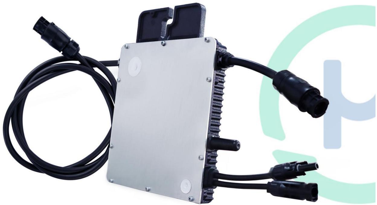
This system is composed of a group of Microinverters that convert direct current (DC) into alternating current (AC) and feeds it into the public grid. The system is designed for the incorporation of one Microinverter for two photovoltaic modules. Each Microinverter works independently that guarantees the maximum power generation of each photovoltaic module. This setup enables user to control the production of a single photovoltaic module directly, consequently improving the flexibility and reliability of the system
About the Manual
This manual contains important instructions for the HM-300/HM-350/HM-400 Microinverter and must be read in its entirety before installing or commissioning the equipment. For safety, only qualified technician, who has received training or has demonstrated skills can install and maintain this Microinverter under the guide of this document.
Other Information
Product information is subject to change without notice. User manual will be updated frequently, please refer to Hoymiles official website at www.hoymiles.com for the latest version.
Contents
- Important Notes 5
1.1 Product Range 5
1.2 Target Group 5
1.3 Symbols Used 5
- About Safety 5
2.1 Important Safety Instructions 5
2.2 Explanation of Symbols 6
2.3 Radio Interference Statement 7
- About Product 7
3.1 About Single Unit 7
3.2 Highlights 8
3.3 Terminals Introduction 8
3.4 Dimension(mm) 8
-
About Function 9
4.1 Work Mode 9 -
About Installation 9
5.1 Accessories 9
5.2 Installation Precaution 10
5.3 Space Distance Required 10
5.4 Preparation 10
5.5 Installation Steps 11
- Troubleshooting 15
6.1 Troubleshooting List 15
6.2 Status LED Indicator 18
6.3 On-site Inspection (For qualified installer only) 19
6.4 Routine Maintenance 20
6.5 Replace Microinverter 20
- Decommissions 21
7.1 Decommissions 21
7.2 Storage and Transportation 22
7.3 Disposal 22
- Technical Data 22
8.1 DC Input 23
8.2 AC Output 23
8.3 Efficiency, Safety and Protection 23
8.4 Mechanical Data 24
8.5 Features 24
Appendix 1: 25
Installation Map 25
Appendix 2: 26
WIRING DIAGRAM - 230VAC SINGLE PHASE: 26
WIRING DIAGRAM - 230VAC / 400VAC THREE PHASE: 27
WIRING DIAGRAM -120VAC / 240VAC SPLIT PHASE: 28
WIRING DIAGRAM - 120VAC / 208VAC THREE PHASE: 29
1. Important Notes
1.1 Product Range
This manual describes the assembly, installation, commissioning, maintenance and failure search of the following model of Hoymiles Microinverter:
HM-300
HM-350
HM-400
*Note: "300" means 300W, "350" means 350W, "400" means 400W.
1.2 Target Group
This manual is only for qualified technician, who has been trained or has demonstrated skills can install and maintain this Microinverter under the guide of this document for safety purpose.
1.3 Symbols Used
The safety symbols in this user manual are show as below.
| Symbol | Usage |
| No DANGER | Indicates a hazardous situation that can result in deadly electric shock hazards, other serious physical injury, or fire hazards. |
| WARING | Indicates directions which must be fully understood and followed in entirety in order to avoid potential safety hazards including equipment damage or personal injury. |
| CAUTION | Indicates this points out that the described operation must not be carried out. The reader should stop, use caution and fully understand the operations explained before proceeding. |
2. About Safety
2.1 Important Safety Instructions
The HM-300/HM-350/HM-400 Microinverter is designed and tested according to international safety requirements. However, certain safety precautions must be taken when installing and operating this
inverter. The installer must read and follow all instructions, cautions and warnings in this installation manual.
| ➢All operations including transport, installation, start-up and maintenance, must be carried out by qualified, trained personnel. |
| ➢Before installation, check the unit to ensure free of any transport or handling damage, which could affect insulation integrity or safety clearances. Choose installation location carefully and adhere to specified cooling requirements. Unauthorized removal of necessary protections, improper use, incorrect installation and operation may lead to serious safety and shock hazards or equipment damage. |
| ➢Before connecting the Microinverter to the power distribution grid, contact the local power distribution grid company to get appropriate approvals. This connection must be made only by qualified technical personnel. It is the responsibility of the installer to provide external disconnect switches and Over current Protection Devices (OCPD). |
| ➢Only one photo voltaic module can be connected to one input of the inverter. Do not connect batteries or other sources of power supply. The inverter can be used only if all the technical characteristics are observed and applied. |
| ➢Do not install the equipment in adverse environment conditions such as flammable, explosive, corrosive, extreme high or low temperature, and humid. Do not use the equipment when the safety devices do not work or disabled. |
| ➢Use personal protective equipment, including gloves and eye protection during the installation. |
| ➢Inform the manufacturer about non-standard installation conditions. |
| ➢Do not use the equipment if any operating anomalies are found. Avoid temporary repairs. |
| ➢All repairs should be carried out using only qualified spare parts, which must be installed in accordance with their intended use and by a licensed contractor or authorized Hoymiles service representative. |
| ➢Liabilities arising from commercial components are delegated to their respective manufacturers. |
| ➢Anytime the inverter has been disconnected from the public network, please be extremely caution as some components can retain charge sufficient to create a shock hazard. Prior to touching any part of the inverter please ensure surfaces and equipment are under touch safe temperatures and voltage potentials before proceeding. |
| ➢Hoymiles accepts No liability for damage from incorrect or improper operation. |
| ➢Electrical Installation & Maintenance shall be conducted by licensed electrician and shall comply with Local Wiring Rules. |
2.2 Explanation of Symbols
| Symbol | Usage |
| Treatment To comply with European Directive 2002/96/EC on waste Electrical and Electronic Equipment and its implementation as national law, electrical equipment that has reached the end of its life must be collected separately and returned to an approved recycling facility. Any device no longer required must be returned to an authorized dealer or approved collection and recycling facility. | |
| ! | Caution Do not come within 8 inches (20cm) of the microinverter for any length of time while it is in operation. |
| Danger of high voltages Danger to life due to high voltage in the microinverter. | |
| Beware of hot surface The inverter can become hot during operation. Avoid contact with metal surfaces during operation. | |
| CE | CE mark The inverter complies with the requirements of the Low Voltage Directive for the European Union. |
| Read manual first Please read the installation manual first before installation, operation and maintenance. |
2.3 Radio Interference Statement
This microinverter has been tested and found to comply with the limits for CE EMC, which can provide reasonable protection against harmful energy. However, if not installed according to the instructions, the microinverter may cause harmful interference to radio equipment. There is no guarantee that the interference will not occur in a particular installation.
To confirm that the radio or television reception is interfered by this equipment, you can turn the equipment off and on. If this equipment does cause harmful interference to the radio or television equipment, please try to correct the interference by one or more of the following measures:
1) Relocate the receiving antenna.
2) Increase the separation between the microinverter and the receiving antenna.
3) Place the shield between the microinverter and the receiving antenna, such as metal / concrete roof.
4) Contact your dealer or an experienced radio/TV technician for help.
3. About Product
3.1 About Single Unit
"The world's First Daisy-Chain Single Unit Microinverter" with extremely wide DC input operating voltage range (16-60V) and low start-up voltage (22V only).
Hoymiles Single unit Microinverter HM-300/HM-350/HM-400 is the perfect selection for PV system with uneven number of panels with world's NO.1 CEC weighted efficiency – 96.50% (peak efficiency 96.70%) in 2015.
3.2 Highlights
- Maximum output power up to 300W/350W/400W; Adapted to 60 & 72 cells PV panels.
- Peak efficiency 96.70% ; CEC weighted efficiency 96.50% .
Static MPPT efficiency 99.80% ; Dynamic MPPT efficiency 99.76% in overcast weather. - Power factor (adjustable) 0.8 leading......0.8 lagging.
External antenna for stronger communication with DTU. - High reliability: NEMA6 (IP67) enclosure; 6000V surge protection.
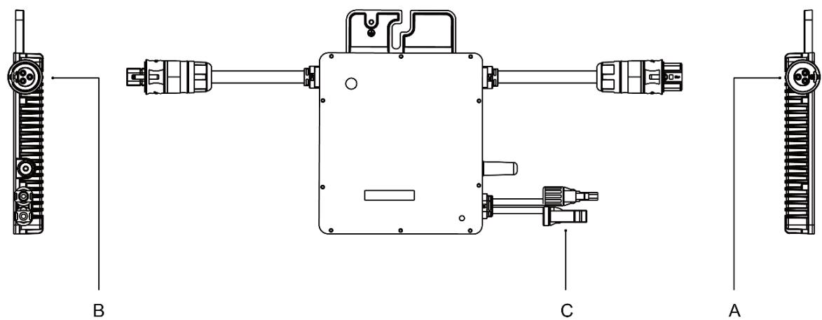
3.3 Terminals Introduction
| Object | Description |
| A | AC Connector (male) |
| B | AC Connector (Female) |
| C | DC Connectors |
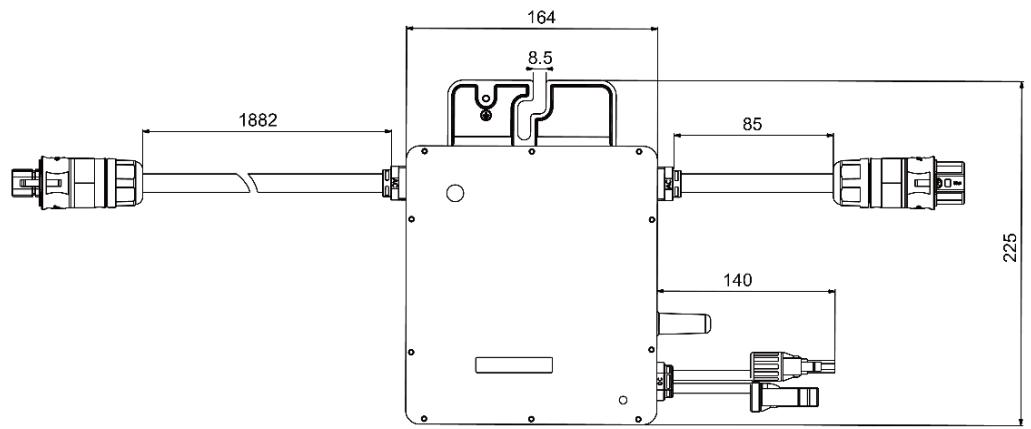
3.4 Dimension(mm)
4. About Function
4.1 Work Mode
Normal: Under this mode, Microinverter is operating normally and convert DC power into AC power to support the house loads and feed in to Public Grid.
Zero Export Control: Under this mode Microinverter's generation is limit base on the current house loads, there will be no extra power feed in to the Public Grid.
Stand by: There are several circumstances that Microinverter will stay in Standby mode:
- The current condition is contradicted with Microinverter operating requirement.
- No house loads or the Export control value has been set as "0" on the DTU under the Zero Export Control mode.
5. About Installation
5.1 Accessories
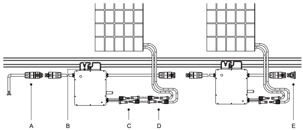
| Object | Description |
| A | AC Female Connector |
| B | M8*25 Screws |
| C | DC Male Connector |
| D | DC Female Connector |
| E | AC Female End Cap, IP67 |
*Note: All accessories above are not included by the package, will need to be purchased separately. Please contact our sales representative for the price (M8 screws will need to be prepared by installer-self).
5.2 Installation Precaution
Please install the Microinverter and all DC connections under the PV module to avoiding direct sunlight, rain exposure, snow layup, UV etc. Allow a minimum of 2 cm of space around the microinverter enclosure.
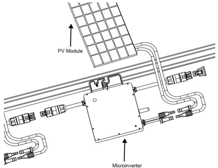
*Note: For some countries the DTU will be required to meet the local grid regulation (e.g. G98/99 for UK etc.)
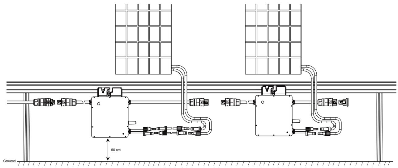
5.3 Space Distance Required
Please install the Microinverter at least 50cm above the ground/roof for better communication with Hoymiles DTU. Please contact with Hoymiles technical engineer if there is any special circumstance.
5.4 Preparation
Installation of the equipment is carried out based on the system design and the place in which the equipment is installed.

The installation must be carried out with the equipment disconnected from the grid (power
disconnect switch open) and with the photovoltaic modules shaded or isolated.
Referring to the Technical Data to make sure the environmental conditions fit the microinverter's requirement (degree of protection, temperature, humidity, altitude, etc.)
To avoid power de-rating due to an increase in the microinverter internal temperature, do not expose it to direct sunlight.
To avoid overheating, always make sure the air flow around the inverter is not blocked.
Do not install in places where gasses or flammable substances may be present.
Avoid electromagnetic interference that can compromise the correct operation of electronic equipment.
When choosing the position of installation, comply with the following conditions:
Install only on structures specifically conceived for photovoltaic modules (supplied by installation technicians).
Install Microinverter underneath of the photovoltaic modules to make sure it works in theshadow. If this condition cannot be met, might trigger the inverter production de-rating.
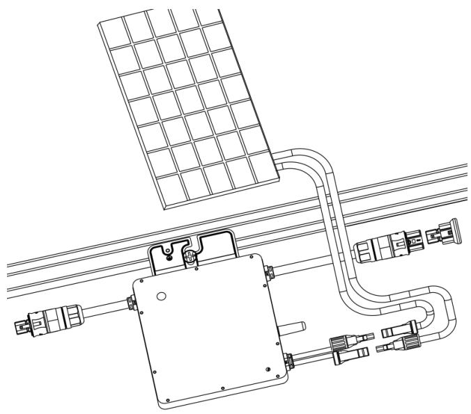
Fig.1 Installation position of microinverter
5.5 Installation Steps
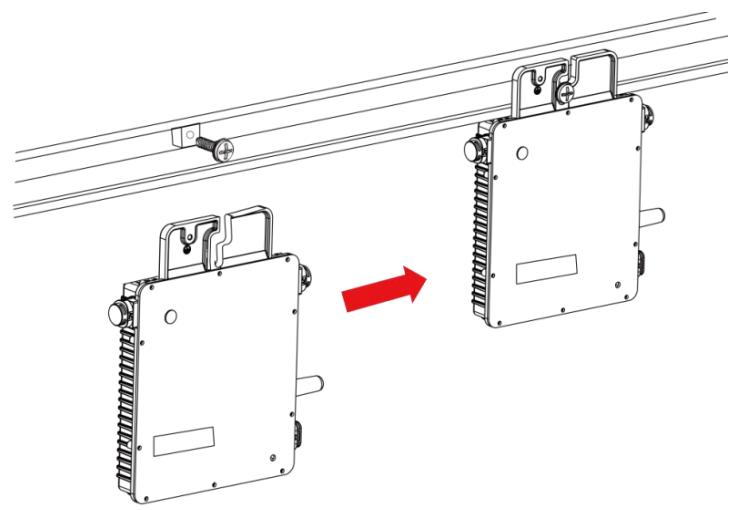
Step 1. Fix Microinverter on the Rail
A) Mark the approximate center of each panel on the frame.
B) Fix the screw on the rail.
C) Hang the microinverter on the screw (shown as picture below), and tighten the screw. The silver cover side of the Microinverter should be facing the panel.
Step 2. Connect AC Cables of Microinverter
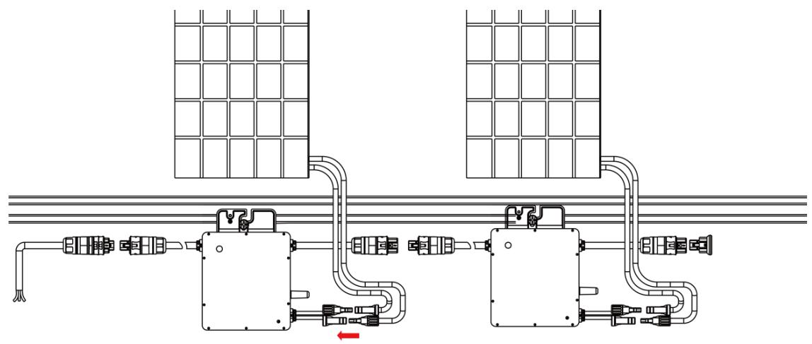
A) Plug the AC connector of the first microinverter with the connector of the second microinverter, to form a continuous AC branch circuit.
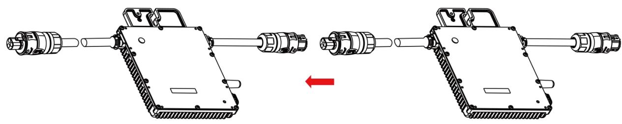
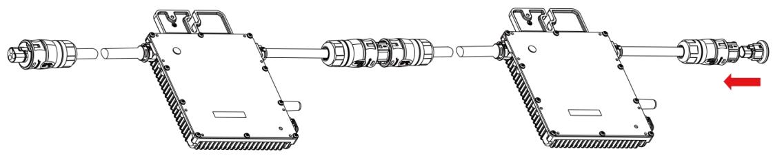
*Note: The length of AC cable on Microinverter is around 1.23m, if the distance between two Microinverters is more than 1.21m please use the AC extension cable between two inverters (As picture indicated below).

B) Install the AC end cap on the open AC connector of the last microinverter in the AC branch circuit.
Step 3. Connect AC End Cable
A) Make the end cable
- Take the AC port apart into 3 parts:

- Insert the AC cable from Part 3 to Part 2, and complete the wiring for the L, N and Ground inside Part 1 AC port accordingly:
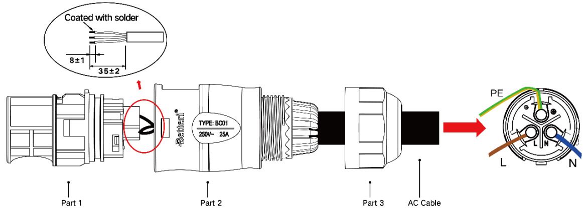
*Note: L: Brown wire N: Blue wire G: Yellow/Green wire
Please use 12 AWG cable as AC end cable.
- Plug the AC port Part 2 into Part 1 once complete the wiring, and screw the Part 3 on and complete the AC extension cable:

B) Connect the AC end cable to the AC male connector of the first Microinverter to complete the circuit.

C) Connect the other side of the AC end cable to the distribution box, and wire it to the local grid
network.
Step 4. Create an Installation Map
A) Peel the removable serial number lable from each microinverter (The position of the label is shown as below.)
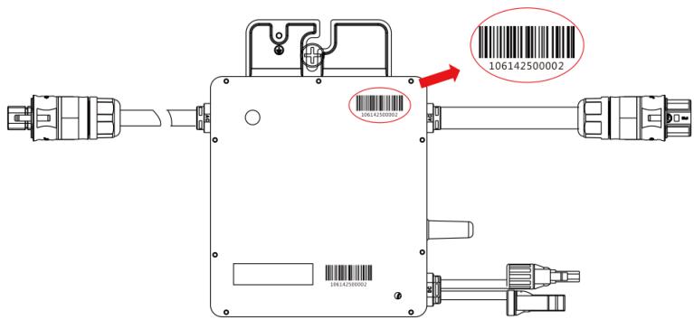
B) Affix the serial number label to the respective location on the installation map.
| N S E W(circle one) | Panel Group:Azimuth:Tilt:Sheet _ of _ | Customer Information: | DTU Serial Number: | ®hoymiles | |||||||||||
| 1 | 2 | 3 | 4 | 5 | 6 | 7 | 8 | 9 | 10 | 11 | 12 | 13 | 14 | ||
| A | |||||||||||||||
| B | |||||||||||||||
| C | |||||||||||||||
| D | |||||||||||||||
Step 5. Connect PV Modules
A) Mount the PV modules above the microinverter.
B) Connect the PV modules' DC cables to the DC input side of the microinverter.
Step 6. Energize the System
A) Turn on the AC breaker of the branch circuit.
B) Turn on the main AC breaker of the house. Your system will start to generate power after about two-minute wait time.
Step 7. Set Up the Monitoring System
Refer to the DTU User Manual or DTU Quick Install Guide, and Quick Installation Guide for HMP Online Registration to install the DTU and set up your monitoring system.
6. Troubleshooting
6.1 Troubleshooting List
| Alarm Code | Alarm Name | Suggestion |
| 121 | Over temperature protection | 1. Check the ventilation and ambient temperature at the microinverter installation position. 2. If the ventilation is poor or the ambient temperature exceeds the limit, improve the ventilation and heat dissipation. 3. If both the ventilation and ambient temperature meet the requirements, contact your dealer or Hoymiles technical support. |
| 125 | Grid configuration parameter error | 1. Check if the grid configuration parameter is correct and upgrade again. 2. If the fault still exists, contact your dealer or Hoymiles technical support. |
| 126 | Software error code 126 | 1. If the alarm occurs accidentally and the microinverter can still work normally, no special treatment is required. 2. If the alarm occurs frequently and cannot be recovered, contact your dealer or Hoymiles technical support. |
| 127 | Firmware error | 1. Check if the firmware is correct and upgrade again. |
| 2. Check the communication between DTU and Hoymiles monitoring system, the communication between DTU and microinverter. Then try again. 3. If the fault still exists, contact your dealer or Hoymiles technical support. | ||
| 128 | Software error code 128 | 1. If the alarm occurs accidentally and the microinverter can still work normally, no special treatment is required. 2. If the alarm occurs frequently and cannot be recovered, contact your dealer or Hoymiles technical support. |
| 129 | Software error code 129 | 1. If the alarm occurs accidentally and the microinverter can still work normally, no special treatment is required. 2. If the alarm occurs frequently and cannot be recovered, contact your dealer or Hoymiles technical support. |
| 130 | Offline | 1. Please make sure that the microinverter works normally. 2. Check the communication status between the DTU and hoymiles monitoring system or between the DTU and the microinverter.If the communication is poor, try to make some improvements. 3. If the alarm occurs frequently and cannot be recovered, contact your dealer or Hoymiles technical support. |
| 141 | Grid overvoltage | 1. If the alarm occurs accidentally, the grid voltage may be abnormal temporarily. The microinverter can recover automatically after grid voltage becomes normal. 2. If the alarm occurs frequently, check whether the grid voltage is within the acceptable range. If no, contact the local power operator or change the grid overvoltage protection limit via Hoymiles monitoring system with the consent of the local power operator. |
| 142 | 10 min value grid overvoltage | 1. If the alarm occurs accidentally, the grid voltage may be abnormal temporarily. The microinverter can recover automatically after grid voltage becomes normal. 2. If the alarm occurs frequently, check whether the grid voltage is within the acceptable range. If no, contact the local power operator or change the grid overvoltage protection limit via Hoymiles monitoring system with the consent of the local power operator. |
| 143 | Grid undervoltage | 1. If the alarm occurs accidentally, the grid voltage may be abnormal temporarily. The microinverter can recover automatically after grid voltage becomes normal. 2. If the alarm occurs frequently, check whether the grid voltage is within the acceptable range. If no, contact the local power operator or change the grid undervoltage protection limit via Hoymiles monitoring system with the consent of the local power operator. 3. If the fault still exists, check the AC switch or AC wiring. |
| 144 | Grid overfrequency | 1. If the alarm occurs accidentally, the grid frequency may be abnormal temporarily. The microinverter can recover automatically after grid frequency becomes normal. |
| 2. If the alarm occurs frequently, check whether the grid frequency is within the acceptable range. If no, contact the local power operator or change the grid overfrequency protection limit via Hoymiles monitoring system with the consent of the local power operator. | ||
| 145 | Grid underfrequency | 1. If the alarm occurs accidentally, the grid frequency may be abnormal temporarily. The microinverter can recover automatically after grid frequency becomes normal. 2. If the alarm occurs frequently, check whether the grid frequency is within the acceptable range. If no, contact the local power operator or change the grid underfrequency protection limit via Hoymiles monitoring system with the consent of the local power operator. |
| 146 | Rapid grid frequency change rate | 1. If the alarm occurs accidentally, the grid frequency may be abnormal temporarily. The microinverter can recover automatically after grid frequency becomes normal. 2. If the alarm occurs frequently, check whether the grid frequency change rate is within the acceptable range. If no, contact the local power operator or change the grid frequency change rate limit via Hoymiles monitoring system with the consent of the local power operator. |
| 147 | Power grid outage | Please check whether there is a power grid outage. |
| 148 | Grid disconnection | Please check whether the AC switch or AC wiring is normal. |
| 149 | Island detected | 1. If the alarm occurs accidentally, the grid voltage may be abnormal temporarily. The microinverter can recover automatically after grid voltage becomes normal. 2. If the alarms occur frequently on all the microinverters in your station, contact the local power operator to check whether there is a grid island. 3. If the alarm still exists, contact your dealer or Hoymiles technical support. |
| 205 | Input port overvoltage | 1.Please make sure that the PV module open-circuit voltage is less than or equal to the maximum input voltage. 2. If the PV module open-circuit voltage is within the normal range, contact your dealer or Hoymiles technical support. |
| 207 | Input port undervoltage | 1.Please make sure that the PV module open-circuit voltage is less than or equal to the maximum input voltage. 2. If the PV module open-circuit voltage is within the normal range, contact your dealer or Hoymiles technical support. |
| 209 | Port No input | 1. Please confirm whether this port is connected to the PV module; 2. If the PV module is connected, please check the DC cable connection between this port and the PV module. |
| 301 | Hardware Error Code 301 | 1. If the alarm occurs accidentally and the microinverter can still work normally, no special treatment is required. 2. If the alarm occurs frequently and cannot be recovered, contact your dealer or Hoymiles technical support. |
| 302 | Hardware Error Code 302 | 1. If the alarm occurs accidentally and the microinverter can still work normally, no special treatment is required. 2. If the alarm occurs frequently and cannot be recovered, contact your dealer or Hoymiles technical support. |
| 303 | Hardware Error Code 303 | 1. If the alarm occurs accidentally and the microinverter can still work normally, no special treatment is required. 2. If the alarm occurs frequently and cannot be recovered, contact your dealer or Hoymiles technical support. |
| 304 | Hardware Error Code 304 | 1. If the alarm occurs accidentally and the microinverter can still work normally, no special treatment is required. 2. If the alarm occurs frequently and cannot be recovered, contact your dealer or Hoymiles technical support. |
| 305 | Hardware Error Code 305 | 1. If the alarm occurs accidentally and the microinverter can still work normally, no special treatment is required. 2. If the alarm occurs frequently and cannot be recovered, contact your dealer or Hoymiles technical support. |
| 306 | Hardware Error Code 306 | 1. If the alarm occurs accidentally and the microinverter can still work normally, no special treatment is required. 2. If the alarm occurs frequently and cannot be recovered, contact your dealer or Hoymiles technical support. |
| 307 | Hardware Error Code 307 | 1. If the alarm occurs accidentally and the microinverter can still work normally, no special treatment is required. 2. If the alarm occurs frequently and cannot be recovered, contact your dealer or Hoymiles technical support. |
| 308 | Hardware Error Code 308 | 1. If the alarm occurs accidentally and the microinverter can still work normally, no special treatment is required. 2. If the alarm occurs frequently and cannot be recovered, contact your dealer or Hoymiles technical support. |
6.2 Status LED Indicator
The LED flashes five times at start up. All green flashes (1s gap) indicate normal start up.
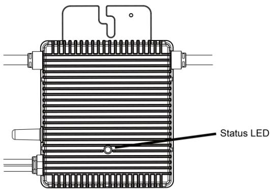
(1) Start-up Process
Flashing green five times (0.3s gap): Start-up success
Flashing Red five times (0.3s gap): Start-up failure
(2) Run Process
Flashing Fast Green (1s gap): Producing power.
Flashing Slow Green (2s gap): Producing power but one input is abnormal.
Flashing Slow Green (4s gap): Producing power but there is no communication with DTU.
Flashing Red (1s gap): Not producing power AC grid invalid (Voltage or frequency out of range).
Flashing Red (0.5s gap): There is a fault except the abnormality of grid.
(3) Other Status
Flashing Red and Green alternately: Firmware is corrupted.
*Note: All the faults are reported to the DTU, refer to the local APP of the DTU or Hoymiles Monitoring Platform for more information.
6.3 On-site Inspection (For qualified installer only)
To troubleshoot an inoperable microinverter, follow the steps in the order shown.
- Verify the utility voltage and frequency are within ranges shown in the in appendix Technical Data of this microinverter.
- Check the connection to the utility grid. Verify utility power is present at the inverter in question by removing AC, then DC power. Never disconnect the DC wires while the microinverter is producing power. Re-connect the DC module connectors and watch for five short LED flashes.
- Check the AC branch circuit interconnection between all the microinverters. Verify each inverter is energized by the utility grid as described in the previous step.
- Make sure that any AC breaker are functioning properly and are closed.
- Check the DC connections between the microinverter and the PV module.
- Verify the PV module DC voltage is within the allowable range shown in appendix Technical Data of this manual.
- If the problem persists, please call Hoymiles customer support.

Warning
Do not try to repair the microinverter. If the troubleshooting fails, please return it to the factory for replacement.
6.4 Routine Maintenance
- Only authorized personnel are allowed to carry out the maintenance operations and are responsible to report any anomalies.
- Always use the personal protective equipment provided by the employer when carry out the maintenance operation.
- During normal operation, check that the environmental and logistic conditions are correct. Make sure that the conditions have not changed over time and that the equipment is not exposed to adverse weather conditions and has not been covered with foreign bodies.
- DO NOT use the equipment if any problems are found, and restore the normal conditions after the fault removed.
- Conduct an annual inspection on various components, and clean the equipment with a vacuum cleaner or special brushes.

Do not attempt to dismantle the Microinverter or make any internal repairs! In order to preserving the integrity of safety and insulation, the Microinverters are not designed to allow internal repairs!

The AC output wiring harness (AC drop cable on the Microinverter) cannot be replaced. If the cord is damaged the equipment should be scrapped.

Maintenance operations must be carried out with the equipment disconnected from the grid (power switch open) and the photovoltaic modules obscured or isolated, unless otherwise indicated.

For cleaning, do not use rags made of filamentary material or corrosive products that may corrode parts of the equipment or generate electrostatic charges.

Avoid temporary repairs. All repairs should be carried out using only genuine spare parts.

If all the microinverters connect to the DTU-Pro, the DTU can limit the output power imbalance of all the microinverters between phases to below 3.68kW if required. Please refer to “Hoymiles Technical Note Limit Phase Balance” for more details.

Each branch should provide a circuit breaker, but no need for central protection unit.
6.5 Replace Microinverter
a. How to remove the Microinverter.
De-energize the AC branch circuit breaker.
Remove the PV panel from the racking, and cover the panel.
Using a meter to measure and make sure there is no current flowing in the DC wires between panel and microinverter.
Use the DC disconnect tool to remove the DC connectors.
Use the AC disconnect tool to remove the AC connectors.
Un-screw the fixing screw on the top of the microinverter and remove the microinverter from the PV racking.
b. How to replace the Microinverter:
Please record down the new Microinverter's SN.
Please make sure the AC branch circuit breaker if off, and following the Microinverter installation steps to install the replacement unit.
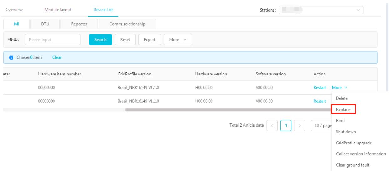
Go to the monitoring platform (if customer already register this station online), please access the "Device List" page and find the device that you just replaced. Please click the down arrow next to the "More" on the right side of the page, and select "Replace". Input the new Microinverter's SN and click "Ok" to complete the station changes.
7. Decommissions
7.1 Decommissions
Disconnect the inverter from DC input and AC output; remove all connection cable from the Microinverter; remove the Microinverter from the frame.
Please pack the Microinverter with the original packaging, or use the carton box that can afford 5kg weight and can be fully closed if the original packaging is no longer available.
7.2 Storage and Transportation
Hoymiles packages and protects individual components using suitable means to make the transport and subsequent handling easier. Transportation of the equipment, especially by road, must be carried out by suitable ways for protecting the components (in particular, the electronic components) from violent, shocks, humidity, vibration, etc. Please dispose the packaging elements in appropriate ways to avoid unforeseen injury.
It is the customer's responsibility to examine the condition of the components transported. Once receiving the Microinverter, it is necessary to check the container for any external damage and verify receipt of all items. Call the delivering carrier immediately if damage or shortage is detected. If inspection reveals damage to the inverter, contact the supplier, or authorized distributor for a repair/return determination and instructions regarding the process.
The microinverter storage temperature is -40 - 85^
7.3 Disposal
- If the equipment is not used immediately or is stored for long periods, check that it is correctly packed. The equipment must be stored in well-ventilated indoor areas that do not have characteristics that might damage the components of the equipment.
Take a complete inspection when restarting after a long time or prolonged stop. - Please dispose the equipment properly after scrapping, which are potentially harmful to the environment, in accordance with the regulations in force in the country of installation.
8. Technical Data

Warning
Be sure to verify the following before installing Hoymiles Microinverter System.
Verify that the voltage and current specifications of the PV module must match those of the microinverter.
The maximum open circuit voltage rating of the PV module must within the operating voltage range of the microinverter.
The maximum current rating at MPP is recommended to be equal to or less than the maximum input DC current. But the maximum short circuit current must be equal to or less than the maximum input DC short circuit current.
The output DC power of PV module is NOT recommended to exceed 1.35 times the output AC power of the microinverter. Refer to "Hoymiles Warranty Terms & Conditions" for more informatio
8.1 DC Input
| Model | HM-300 | HM-350 | HM-400 |
| Commonly used module power (W) | Up to 380 (single panel) | Up to 440 (singe panel) | Up to 500 (singe panel) |
| Peak power MPPT voltage range (V) | 29~48 | 33~48 | 34~48 |
| Start-up voltage (V) | 22 | 22 | 22 |
| Operating voltage range (V) | 16~60 | 16~60 | 16~60 |
| Maximum input voltage (V) | 60 | 60 | 60 |
| Maximum input current (A) | 11.5 | 11.5 | 12.5 |
| Maximum input short circuit current (A) | 15 | 15 | 15 |
8.2 AC Output
| Model | HM-300 | HM-350 | HM-400 |
| Rated output power (VA) | 300 | 350 | 400 |
| Rated output current (A) | 1.36@220V | 1.59@220V | 1.82@220V |
| 1.30@230V | 1.52@230V | 1.74@230V | |
| 1.25@240V | 1.46@240V | 1.67@240V | |
| Nominal output voltage/range (V) | 220/180-275 | 220/180-275 | 220/180-275 |
| 230/180-275 | 230/180-275 | 230/180-275 | |
| 240/180-275 | 240/180-275 | 240/180-275 | |
| Nominal frequency/range (Hz) | 45-55 (under 50Hz @ 220V & 230V)55-65 (under 60Hz @ 220V & 230V) | ||
| Power factor | >0.99 default0.8 leading......0.8 lagging | ||
| Output current harmonic distortion | <3% | <3% | <3% |
| Maximum units per branch | 16@220V | 14@220V | 12@220V |
| 16@230V | 14@230V | 12@230V | |
| 16@240V | 14@240V | 12@240V | |
8.3 Efficiency, Safety and Protection
| Model | HM-300 | HM-350 | HM-400 |
| Peak inverter efficiency | 96.70% | 96.70% | 96.70% |
| CEC weighted efficiency | 96.50% | 96.50% | 96.50% |
| Nominal MPPT efficiency | 99.80% | 99.80% | 99.80% |
| Night time power consumption (mW) | <50 | <50 | <50 |
8.4 Mechanical Data
| Model | HM-300 | HM-350 | HM-400 |
| Ambient temperature range (℃) | -40 ~ +65 | -40 ~ +65 | -40 ~ +65 |
| Storage temperature range (℃) | -40 ~ +85 | -40 ~ +85 | -40 ~ +85 |
| Dimensions (W×H×D mm) | 182×164×29.5 | 182×164×29.5 | 182×164×29.5 |
| Weight (kg) | 1.98 | 1.98 | 1.98 |
| Enclosure rating | Outdoor-NEMA (IP67) | ||
| Cooling | Natural convection – No fans | ||
8.5 Features
| Model | HM-300 | HM-350 | HM-400 |
| Communication | 2.4GHz Proprietary RF(Nordic) | ||
| Monitoring | Hoymiles Monitoring System (Hoymiles DTU is required) | ||
| Warranty | 12 years standard, 25 years optional | ||
| Compliance | VDE-AR-N 4105:2018, EN50549-1:2019, VFR2019, AS 4777.2:2015, IEC/EN 62109-1/-2, IEC/EN 61000-3-2/-3, IEC/EN-61000-6-1/-2/-3/-4 | ||
*Note: Voltage and frequency ranges can be extended beyond nominal if required by the utility.
Appendix 1:
Installation Map
| N W E S | Panel Group: Azimuth: Tilt: Sheet_of_ | Customer Information: | DTU Serial Number: | hoymiles | |||||||||||
| 1 | 2 | 3 | 4 | 5 | 6 | 7 | 8 | 9 | 10 | 11 | 12 | 13 | 14 | ||
| A | |||||||||||||||
| B | |||||||||||||||
| C | |||||||||||||||
| D | |||||||||||||||
Appendix 2:
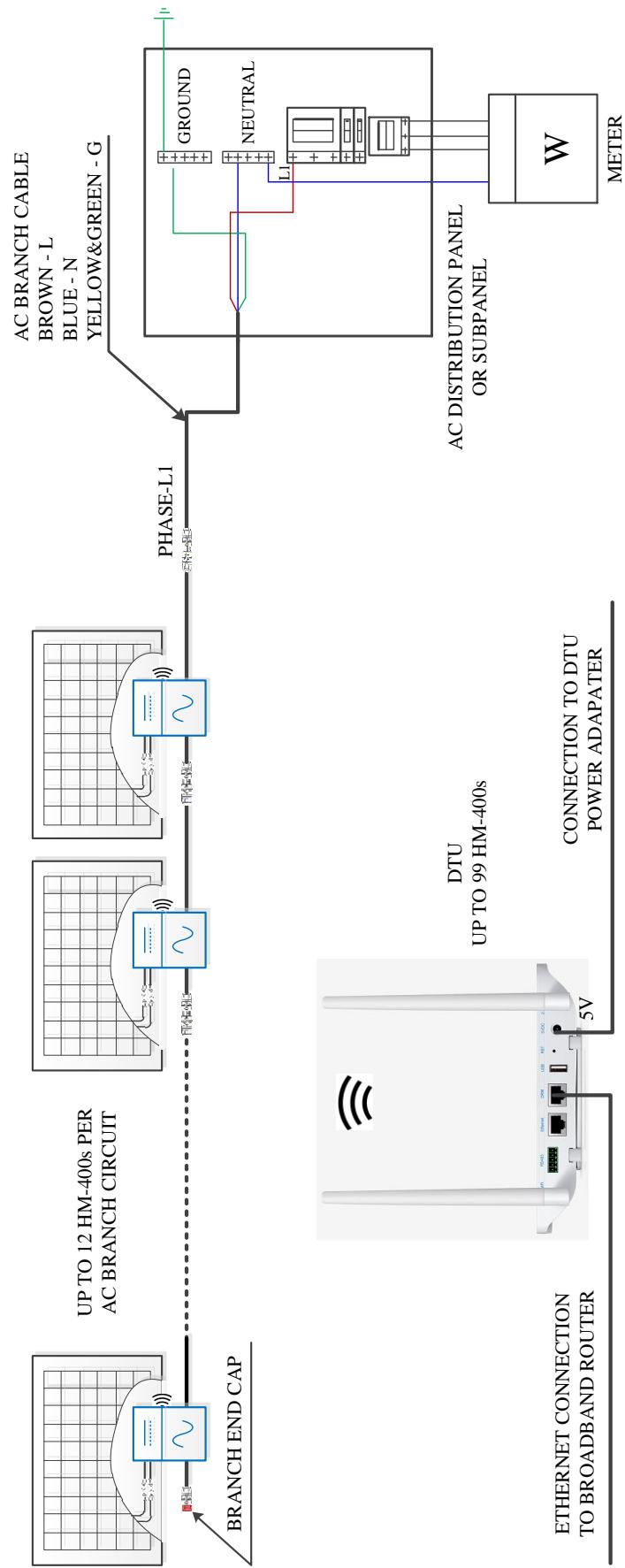
WIRING DIAGRAM - 230VAC SINGLE PHASE:
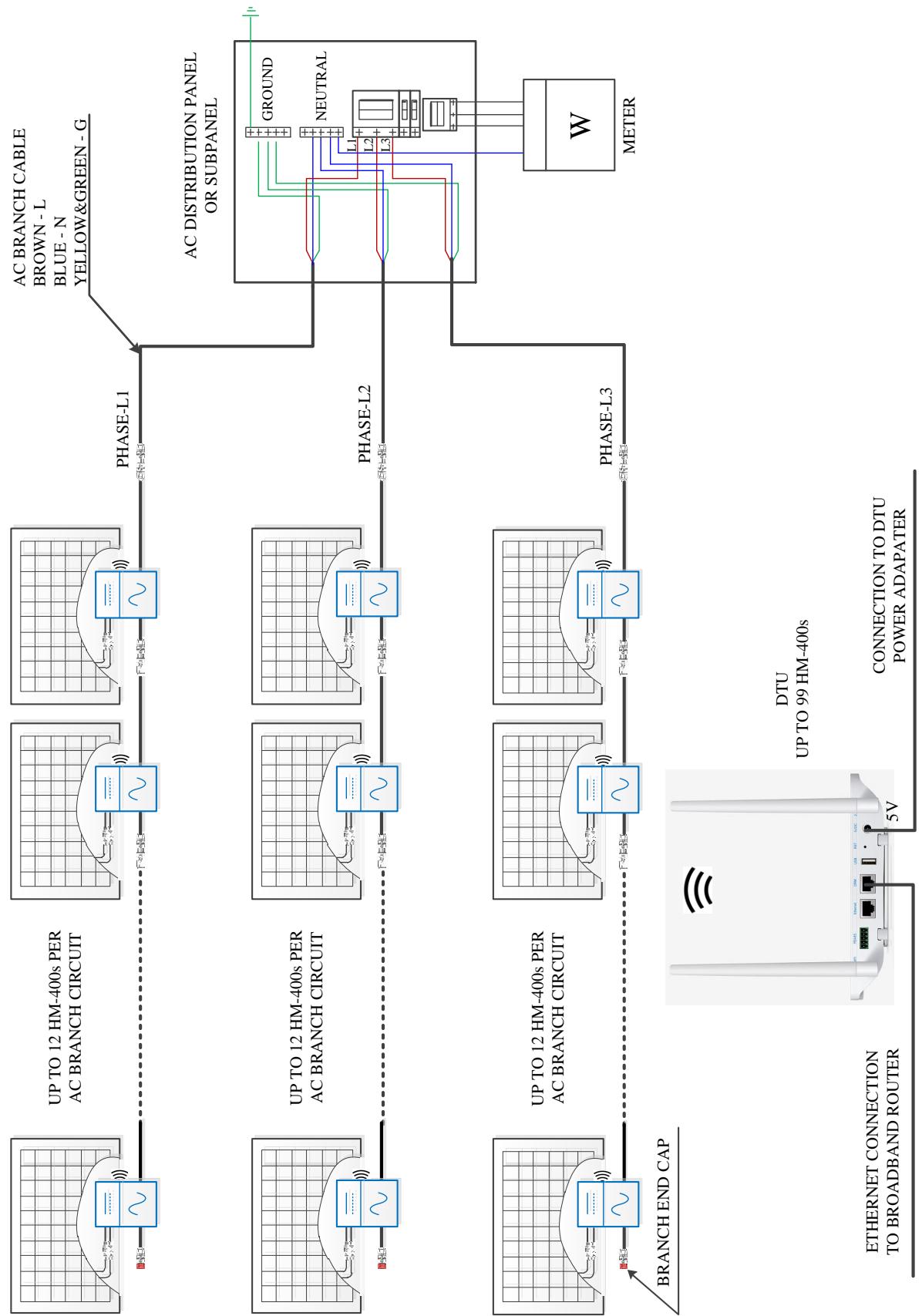
WIRING DIAGRAM - 230VAC / 400VAC THREE PHASE:
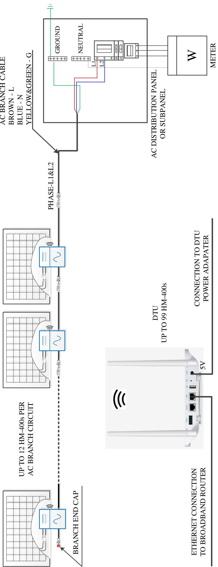
WIRING DIAGRAM -120VAC / 240VAC SPLIT PHASE:
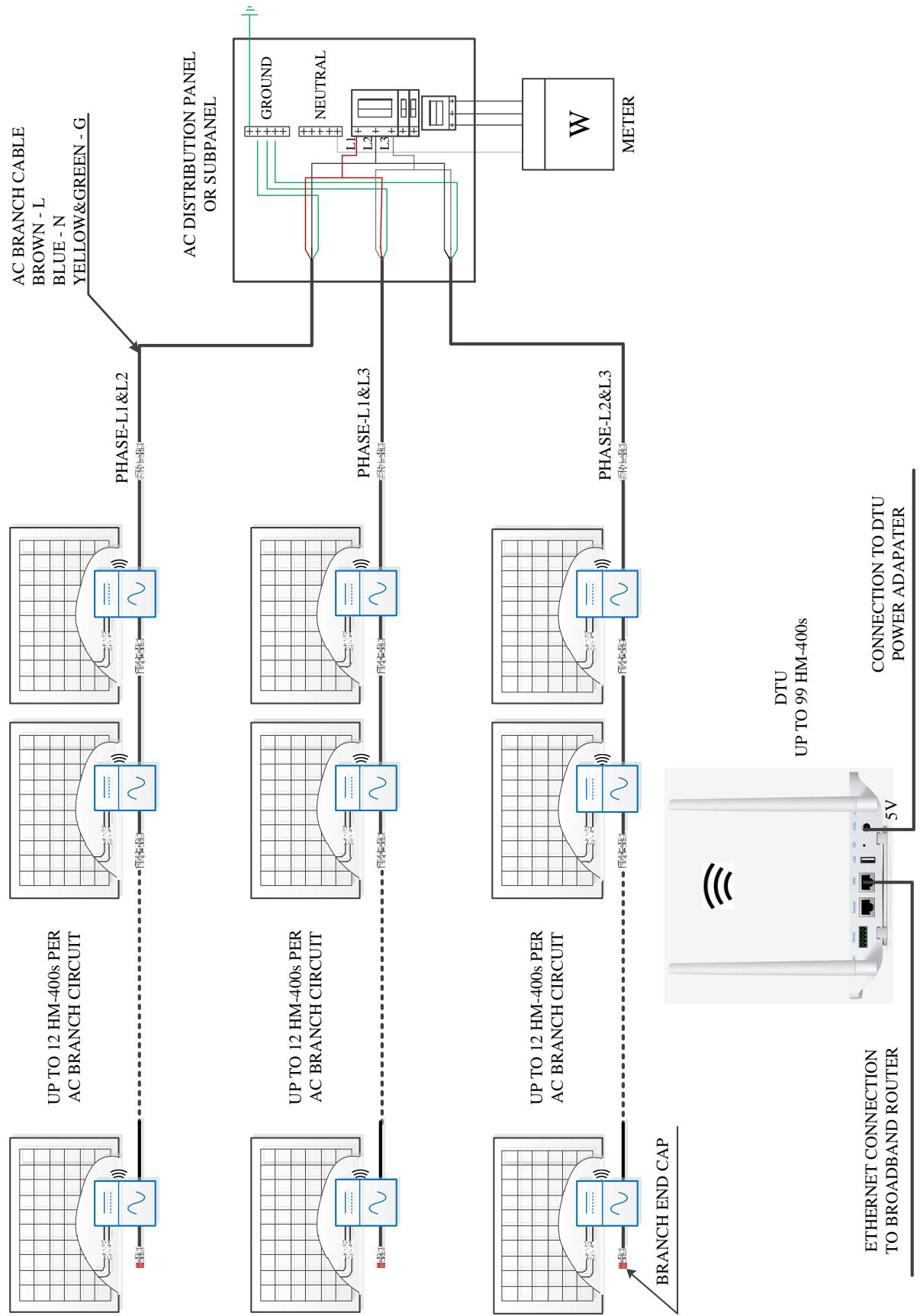
WIRING DIAGRAM - 120VAC / 208VAC THREE PHASE: