
PHANTOM 4 RTK - Drone professionnel DJI - Notice d'utilisation et mode d'emploi gratuit
Retrouvez gratuitement la notice de l'appareil PHANTOM 4 RTK DJI au format PDF.
| Type de produit | Drone professionnel |
| Marque | DJI |
| Modèle | Phantom 4 RTK |
| Dimensions (diagonale, sans hélices) | 350 mm |
| Poids (avec batterie et hélices) | 1391 g |
| Vitesse maximale | 50 km/h (P-mode), 58 km/h (A-mode) |
| Temps de vol maximum | Env. 30 minutes |
| Altitude maximale de service | 6000 m |
| Résistance au vent max. | 10 m/s |
| Batterie | LiPo 4S 15.2 V, 5870 mAh, 89.2 Wh |
| Capteur | CMOS 1 pouce, 20 Mpx |
| Objectif | 24 mm (équiv. 35 mm), f/2.8 - f/11 |
| Résolution vidéo max. | 4K à 30 ips, 100 Mbps |
| Système de positionnement | GNSS + RTK centimétrique (D-RTK intégré) |
| Système de vision | Avant, arrière, inférieur (stéréo) + infrarouge latéral |
| Portée de la télécommande | Jusqu'à 7 km (FCC), 5 km (CE) |
| Écran de la télécommande | 5,5 pouces, 1920×1080, 1000 cd/m² |
| Température de fonctionnement | 0°C à 40°C |
| Entretien | Nettoyer capteurs et hélices régulièrement ; calibrer boussole si nécessaire |
| Sécurité | Zones GEO, retour automatique (RTH), évitement d'obstacles |
| Pièces détachées | Hélices, batteries, chargeurs, télécommande, câbles |
| Réparabilité | Mise à jour firmware via DJI Assistant 2 ou application |
| Garantie | Consulter les conditions DJI |
FOIRE AUX QUESTIONS - PHANTOM 4 RTK DJI
Questions des utilisateurs sur PHANTOM 4 RTK DJI
0 question sur cet appareil. Repondez a celles que vous connaissez ou posez la votre.
Poser une nouvelle question sur cet appareil
Téléchargez la notice de votre Drone professionnel au format PDF gratuitement ! Retrouvez votre notice PHANTOM 4 RTK - DJI et reprennez votre appareil électronique en main. Sur cette page sont publiés tous les documents nécessaires à l'utilisation de votre appareil PHANTOM 4 RTK de la marque DJI.
MODE D'EMPLOI PHANTOM 4 RTK DJI
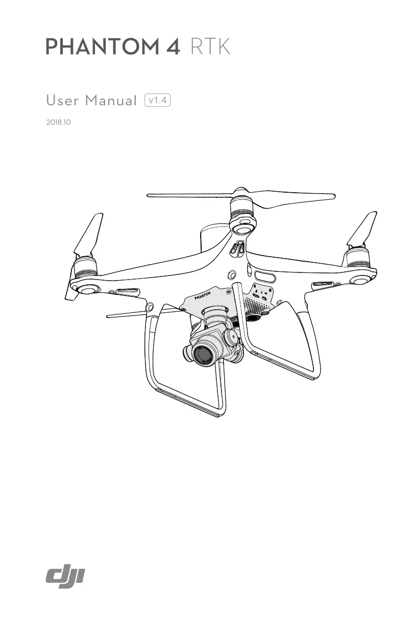
PHANTOM 4 RTK
User Manual v1.4
2018.10
natural_image
Line drawing of a quadrupedal drone with visible cockpit and propeller components (no text or symbols)
Searching for Keywords
Search for keywords such as “battery” and “install” to find a topic. If you are using Adobe Acrobat Reader to read this document, press Ctrl+F on Windows or Command+F on Mac to begin a search.

Navigating to a Topic
View a complete list of topics in the table of contents. Click on a topic to navigate to that section.

Printing this Document
This document supports high resolution printing.
Information
There are two kinds of altitudes displayed in the DJI GS RTK app, absolute altitude and relative altitude.
Absolute altitude: The geographical attribute, in relation to longitude and latitude.
Relative altitude: The altitude data of the operation tasks relative to the Home Point. In the same operation, the absolute altitude for the same point during the operation will vary when taking off from locations with different elevations.
Using this manual
Legends

Warning

Important

Hints and Tips

Reference
Read Before the First Flight
Read the following documents before using the PHANTOM ^TM 4 RTK:
- In the Box
- User Manual
- Quick Start Guide
- Disclaimer and Safety Guidelines
- Intelligent Flight Battery Safety Guidelines
We recommend that you watch all tutorial videos on the official DJI ^™ website and read the Disclaimer and Safety Guidelines before you fly. Prepare for your first flight by reviewing the Quick Start Guide and refer to the User Manual for more details.
Watch the Tutorial Videos
Please watch the tutorial videos at the link below, which demonstrates how to use the Phantom 4 RTK safely: http://www.dji.com/product/phantom-4-rtk/info#video

Download the DJI Assistant 2 for Phantom
Download DJI ASSISTANT™ 2 for Phantom from: http://www.dji.com/phantom-4-rtk/info#downloads

The operating temperature of this product is 0^ to 40^ C. It does not meet the standard operating temperature for military grade application ( -55^ to 125^ C), which is required to endure greater environmental variability. Operate the product appropriately and only for applications that it meets the operating temperature range requirements of that grade.
Contents
Information 2
Using this manual 2
Legends 2
Read Before the First Flight 2
Watch the Tutorial Videos 2
Download the DJI Assistant 2 for Phantom 2
Product Profile 6
Introduction 6
Features Highlights 6
Installation 6
Aircraft Overview 9
Remote Controller Overview 10
Aircraft 13
Profile 13
Flight Modes 13
Aircraft Status Indicators 14
Return to Home (RTH) 15
Industrial Applications 20
Vision System and Infrared Sensing System 24
RTK Functions 27
Flight Recorder 28
Attaching and Detaching the Propellers 28
DJI Intelligent Flight Battery 29
Remote Controller 35
Profile 35
Using the Remote Controller 35
Remote Controller Status LED 39
Linking the Remote Controlle 40
Multi-Aircraft Control Function 41
Gimbal and Camera 44
Camera 44
Gimbal 46
DJI GS RTK App 48
Main Screen 48
Planning View 49
Camera View 51
Flight 55
Flight Environment Requirements 55
GEO (Geospatial Environment Online) System 55
Flight Restrictions 56
GEO Unlocking 58
Preflight Checklist 59
Calibrating the Compass 59
Starting/Stopping the Motors 60
Stopping Motors Mid-flight 60
Flight Test 61
DJI Assistant 2 for Phantom 63
Installation and Launching 63
Using DJI Assistant 2 for Phantom 63
Appendix 65
Specifications 65
Updating the Firmware 68
Product Profile
This section introduces the Phantom 4 RTK and lists the components of the aircraft and remote controller.
Product Profile
Introduction
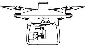
The Phantom 4 RTK is a smart mapping and imaging drone capable of highly accurate mapping functions. The aircraft has a built-in DJI Onboard D-RTK ^™ , which provides precision data for centimeter-level positioning accuracy*. Multi-directional obstacle sensing achieved through vision and infrared sensors enables intelligent obstacle avoidance during flight and indoor hovering and flight. The Phantom 4 RTK records videos at 4K and captures 20 megapixel photos. The OCUSYNC ^™ HD video downlink built into both the aircraft and remote controller ensures a reliable and stable transmission.
Features Highlights
The Phantom 4 RTK aircraft has a built-in DJI Onboard D-RTK, providing high-precision data for centimeter-level positioning when used with Network RTK service or a DJI D-RTK 2. Raw satellite observations and exposure event records can be used for post-processed kinematic (PPK) differential corrections.
The Phantom 4 RTK can hover and fly in extremely low altitude and indoor environments, and provides multi-directional obstacle sensing and vision positioning functions. Obstacles detection and avoidance in large range and landing protection enhance flight safety.
The Phantom 4 RTK is equipped with a 24 mm (35 mm format equivalent) wide angle camera, high-precision and anti-shake gimbal, 1-inch CMOS sensor, mechanical shutter to offer the best in aerial photo analysis.
Built into the remote controller is the latest DJI OcuSync technology with enhanced anti-interference capability to deliver a more stable and smoother video downlink. When combined with the receiver in the aircraft, the remote controller has a transmission range up to 4.3 mi / 7 km (FCC-compliant version). The remote controller is equipped with a 5.5-inch high luminance monitor, and an integrated DJI GS RTK App for real-time HD display. Users can plan flight paths and perform flight operations in the app for both photogrammetry and waypoint flights. For photogrammetry operations, simply tap on the map in the app to set a flight area. For waypoint operations, fly the aircraft to set waypoints and configure waypoint actions, then the aircraft will be able to perform automated operations.
The remote controller's Multi-Aircraft Control mode can be used to coordinate the operation of up to five aircraft at the same time, enabling pilots to work very efficiently.
Image data from the Phantom 4 RTK can be used to generate maps for field planning when operating a DJI AGRASTM aircraft. Users can also import photos to the DJI PC GS Pro application or third-party mapping software to composite highly accurate maps for different applications.
Installation
Preparing the Aircraft
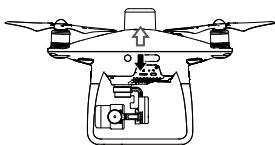
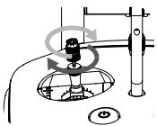
- Remove the gimbal clamp from the camera as shown below:

natural_image
Mechanical assembly diagram showing a central rotating component with attached brackets and a downward arrow indicating motion (no text or symbols present)* This should be used with Network RTK service, a DJI D-RTK 2 High-Precision GNSS Mobile Station (purchased additionally) or post-processed kinematic (PPK) data (recommended when RTK signal is weak during operation).
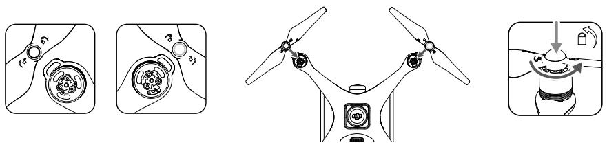
2. Attaching the Propellers
Mount the propellers with black propeller rings to the motors with black dots. Mount the propellers with sliver propeller rings to the motors without black dots. Press the propeller down onto the mounting plate and rotate in the lock direction until it is secured.
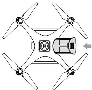
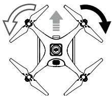
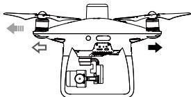
3. Battery Installation
Slide battery into the battery compartment according to the arrow's direction as shown below.
natural_image
Top-down diagram of a drone with four propellers and a central control unit (no text or symbols)
When the upper and lower buckles on the battery are in place, a click sound indicates the battery is securely installed. Failure to do so may affect the flight safety of your aircraft.
Preparing the Remote Controller
1. Mounting the Remote Controller Battery
The remote controller uses an easily removable interchangeable Intelligent Battery for long-term operation.
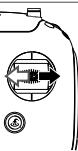
① Slide the battery compartment cover lock on the back of the remote controller down to open the cover.
② Insert the Intelligent Battery into the compartment and push it to the top.
③ Close the cover.


To remove the Intelligent Battery, open the cover, press and hold the battery release button, then push the battery downward.
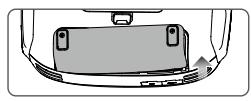
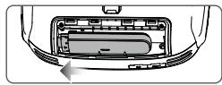
2. Mounting the Dongle and SIM Card
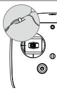
① Lift the dongle compartment cover at the gap at its lower right corner, then remove it.
② Insert the dongle into the USB port with the SIM card inserted into the dongle and test. *
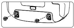
③ Re-mount the cover. To secure the cover, open the silicone protectors on it, insert and tighten two Phillips screws, then close the protectors.
natural_image
Top-down view of a car's rear bumper area showing no text or symbols▶
natural_image
Diagram of a car interior showing internal components and a directional arrow (no text or symbols)▶
natural_image
Diagram of a car's rear panel showing two connectors with plus signs, no text or symbols present* Test procedure: Press the remote controller power button once, then press again and hold to turn the remote controller on. In the DJI GS RTK app tap > and select Network Diagnostics. If the statuses of all the devices in the network chain are shown in green the dongle and SIM card are functioning properly.

- The Phantom 4 RTK remote controller can access the Internet using a 4G dongle with SIM card or Wi-Fi signal. For UK, EU, ACUK, or ACEU versions, a Network RTK server can only be accessed using a 4G dongle with SIM card. For NA, AU or AFUS versions, using a 4G dongle with SIM card is recommended, but a Wi-Fi signal can also be used. To confirm the version of your unit, please view the version code after the product name on the label on the product packaging. When uploading or downloading system logs or operation data, using a Wi-Fi signal for Internet access is recommended.
- Only use a DJI approved dongle.
- The dongle supports various network standards. Use a SIM card that is compatible with the chosen mobile network provider and select a mobile data plan according to the planned level of usage.
- The dongle and SIM card are used to enable the remote controller to access to specific networks and platforms, such as the DJI AG platform. Be sure to mount them correctly, or else network access will not be available.
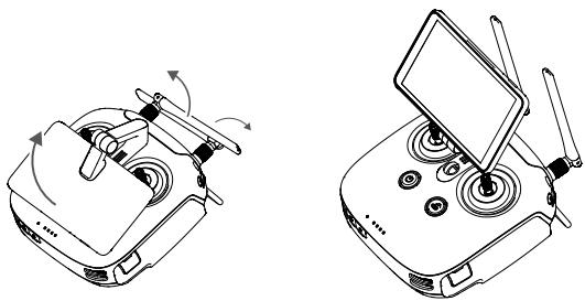
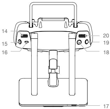
3. Unfolding the Remote Controller
Tilt the display device on the remote controller to the desired position, then adjust the antennas so they are facing outward.
natural_image
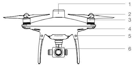
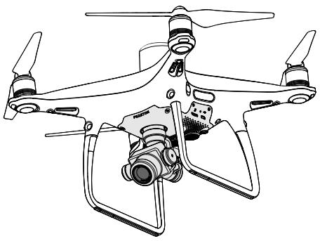
Technical line drawings of a dual-axis remote control device (no text or symbols)Aircraft Overview
natural_image
Top-down line drawing of a four-bladed drone with propellers and a central cockpit (no text or symbols)- Onboard D-RTK Antenna
- Propellers
- Motors
- Front LEDs
- Forward Vision System
- Gimbal and Camera
- Intelligent Flight Battery
- Aircraft Status Indicator
- Rear Vision System
- Infrared Sensing System
- Camera / Linking Status Indicator and Link Button
- Micro USB Port
- Camera microSD Card Slot
- Downward Vision System
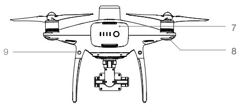
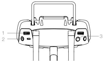
Remote Controller Overview
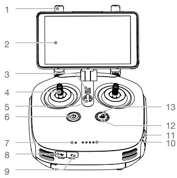
- Antennas
Relays aircraft control signals.
- Display Device
Android-based to run the DJI MG app.
- Speaker
Audio output.
- Control Sticks
Controls aircraft movement. Can be set to Mode 1, Mode 2, or a custom mode.
- Lanyard Attachment
Used to attach the remote controller lanyard.
- Power Button
Used to turn the remote controller on and off.
- Status LED
Indicates whether the remote controller is linked to the aircraft.
- USB-C Port
Connects to a computer via a USB-C cable for configuration. Connects to the aircraft via a USB-C OTG cable and a Micro USB cable for aircraft firmware update.
- 3.5 mm Audio Jack
Used to connect audio input/output devices.
- Battery Level LEDs
Displays current battery level.
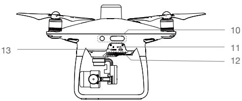
- MicroSD Card Slot
Provides display device with up to 128 GB of extra storage.
- RTH Status LED
Circular LED around the RTH button. Displays RTH status.
- RTH Button
Press and hold this button to initiate Return to Home (RTH).
- Gimbal Dial
Use this dial to control the tilt of the gimbal.
- Video Recording Button
Press to start recording video. Press again to stop recording.
- Pause Switch
During a Photogrammetry or Waypoint operation, toggle to pause the operation.
During RTH, toggle to pause RTH.
- Sleep/Wake Button
Press to sleep/wake the screen; press and hold to restart.
- Shutter Button
Press to take a photo.
-
Reserved Button
-
Aircraft Control Switch Dial
Turn and press the dial to switch among the aircraft when using Multi-Aircraft Control function.
- Button C1
Press Button C1 to switch between Map View and Camera View.
- Button C2
When you are planning a Waypoint Flight operation, it adds a waypoint. The button is disabled in any other operations.
- Battery Compartment Cover
Open the cover to mount or remove the Intelligent Battery from the remote controller.
- Battery Compartment Cover Lock
Slide the lock down to open the cover.
- Dongle Compartment Cover
Open the cover to mount or remove the dongle.
Aircraft
This section introduces the aircraft components, features and functions.
natural_image
Line drawing of a quadcopter drone with four propellers and camera module (no text or symbols)Aircraft
Profile
The Phantom 4 RTK aircraft includes a flight controller, a communication system, a positioning system, a propulsion system and an Intelligent Flight Battery. This section describes the functions of these components.
Flight Modes
The Phantom 4 RTK uses a DJI dedicated flight controller, which provides the flight modes below:
P-mode (Positioning): P-mode works best when the GNSS signal is strong. The aircraft utilizes the GNSS / RTK module and Vision System to automatically stabilize itself, navigate between obstacles, and perform a Photogrammetry or Waypoint Flight operation.
When the GNSS signal is strong, the aircraft uses GNSS for positioning. When RTK module is enabled and the differential data transmission is good, it provides centimeter-level positioning. When the GNSS signal is weak and the lighting conditions are sufficient, the aircraft uses Vision System for positioning.
When the forward obstacle sensing is enabled and lighting conditions are sufficient, the maximum flight attitude angle is 25^ with a maximum flight speed of 31 mph (50 kph). When forward obstacle sensing is disabled, the maximum flight attitude angle is 35^ and the maximum flight speed is 36 mph (58 kph).
A-mode (Attitude): GNSS and Vision System are NOT used for positioning and aircraft can only maintain altitude using the barometer. It enters A-mode only when there is weak GNSS signal or when the compass experiences interference where the Vision System is unavailable.
Attitude Mode Warning
The aircraft will fly in P-mode by default. It enters A-mode only when there is weak GNSS signal or when the compass experiences interference where the Vision System is unavailable.
In A-mode, the Vision System and some advanced features are disabled. Therefore, the aircraft cannot position or auto-brake in this mode and is easily affected by its surroundings, which may result in horizontal shifting. Use the remote controller to position the aircraft.
Maneuvering the aircraft in A-mode can be difficult. Avoid flying in areas where GNSS signal is weak, or in confined spaces. The aircraft will otherwise be forced to enter A-mode, leading to potential flight risks, please land it in a safe place as soon as possible.
Aircraft Status Indicators
The Phantom 4 RTK has Front LEDs and Aircraft Status Indicators. The positions of these LEDs are shown in the figure below:

The Front LEDs show the orientation of the aircraft. The Front LEDs glow solid red when the aircraft is turned on to indicate the front (or nose) of the aircraft. The Aircraft Status Indicators communicate the system status of the flight controller. Refer to the table below for more information about the Aircraft Status Indicators.
Aircraft Status Indicator Description
| Normal | |||||||||||||||||||||||
| DAWWD | DTTO | RADYO | CEFWO | LARGO | CTN480 | DYWTI | ISV7T | ISV7T | DWS3 | DWS40 | DWS41 | CJUNA | DYC31 | DYWD1 | DY680 | DC300 | DC500 | DC500 | DTW7T | DY421 | DYATTI | DYWD3 | DY600 |
| DC500 | DSW70 | DC001 | DC001 | LAWO | DG470 | DWS60 | CY640 | ITTA60 | DC07T | CY77T | DC090 | DWS90 | DC57T | DWWD | DY620 | DSW10 | DY650 | DC570 | DWWD | DC500 | CTN60 | DSW7T | DSW40 |
| DSWD | DT70 | DC07T | CTTO7 | DC001 | DG400 | DYND1 | DWS40 | DG60 | DG60 | CY760 | DG37T | ITTA60 | DC400 | CJUNA | DY760 | DC90T | DC57T | DY680 | DTW70 | DY400 | DC500 | DT700 | DY760 |
| DC500 | DSW70 | DC000 | DC1000 | DC000 | DG400 | DYND1 | DWS40 | DG60 | DG60 | CY760 | DC67T | ITTA60 | DC400 | CJUNA | DY650 | DC900 | DC57T | DY77T | DC57T | DWWD | DY400 | DC500 | |
| DSWD | DC000 | DC000 | DC1000 | DC000 | DG400 | DYND1 | DWS40 | DG60 | DG60 | CY760 | DC67T | ITTA60 | DC400 | CJUNA | DY650 | DC900 | DC57T | DY77T | DC57T | DWWD | DY400 | ||
| DSWD | DC000 | DC000 | DC1000 | DC000 | DG400 | DYND1 | DWS40 | DG60 | DG60 | CY760 | DC67T | ITTA60 | DC400 | CJUNA | DY650 | DC900 | DC57T | DY77T | DC57T | ||||
| DC500 | DSW70 | DC000 | DC1000 | DC000 | DTW60 | DY740 | ITTO80 | DG67T | DWWD40 | DY600 | DY760 | DC670 | DC300 | DC500 | DY750 | DC900 | DC500 | DC500 | |||||
| DC500 | DSW70 | DC000 | DC1000 | DC000 | DTTO80 | DY740 | DWS40 | DY600 | DY760 | DY600 | DC670 | DC300 | DC300 | DY750 | DY750 | DC900 | DC500 | DC500 | |||||
| Fast yellow flashing | |||||||||||||||||||||||
| DC700 | DTW70 | DCW70 | DC1000 | DC000 | DG400 | CY740 | DC600 | CY740 | DC600 | CY760 | DC700 | DY680 | DC600 | DY670 | DC1000 | DC700 | DC640 | DC500 | DY680 | DC500 | DC500 | ||
| DC500 | DTW70 | DCW70 | DC1000 | DC000 | DG400 | CY740 | DC600 | CY740 | DC600 | CY760 | DC670 | DC600 | DY750 | DY680 | DC600 | DC700 | DC640 | DC500 | DY670 | ||||
| DC500 | DTW70 | DCW70 | DC1000 | DC000 | DTW70 | DWS40 | CY740 | DC600 | CY760 | DY720 | DC600 | DC700 | DC600 | DY750 | DC700 | DC640 | DC500 | DC500 | DY740 | DC500 | DC500 | ||
| DC500 | DC200 | DTW70 | DC000 | DC000 | DTW70 | DY740 | DWS40 | DY740 | DC600 | DY760 | DY740 | DC600 | DY680 | DC600 | DY750 | DC640 | DC500 | DC500 | DY740 | DY740 | |||
| DC500 | DC200 | DC200 | DTW70 | DC000 | DTW70 | DY740 | DWS40 | DY740 | DC600 | DY760 | DY740 | DC600 | DY680 | DY670 | DY750 | DC640 | DC500 | DC500 | DY740 | DY740 | |||
Return to Home (RTH)
Return to Home (RTH) function brings the aircraft back to the last recorded Home Point. There are three types of RTH: Smart RTH, Low Battery RTH, and Failsafe RTH. This section describes these three scenarios in detail.
| GNSS | Description | |
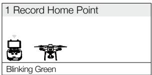
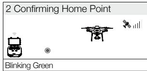
| Home Point | If a strong GNSS signal was acquired before takeoff, the Home Point is the location from which the aircraft launched. The GNSS signal strength is indicated by the GNSS icon ( ✗_|| Less than 4 bars is considered a weak GNSS signal). The aircraft status indicators will blink rapidly when the home point is recorded. |

- The aircraft can sense and avoid obstacles when the Forward Vision System is enabled and lighting conditions are sufficient. The aircraft will automatically climb up to avoid obstacles and descend slowly as it returns to the Home Point. To ensure the aircraft returns home forwards, it cannot rotate or fly left and right during RTH while the Forward Vision System is enabled.
Updating the Home Point
You can update the Home Point in the DJI GS RTK app during flight. There are two options for setting the Home Point:
- Set the aircraft's current coordinates as the Home Point.
- Set the remote controller's current coordinates as the Home Point.

Ensure the space above the remote controller's GNSS module (located beneath the DJI logo) is not obstructed and that there are no tall buildings around when updating the Home Point.
Follow the instructions below to update the Home Point:
- Go to DJI GS RTK > Fly.
- Tap ●●● > ⚙, select ⚠ in Home Point settings to set the aircraft's current coordinates as the Home Point.
- Tap ●●● > ⚙, select ⏱ in Home Point settings to set the remote controller's current coordinates as the Home Point.
- The Aircraft Status Indicator will blink green to indicate that the new Home Point has successfully been set.
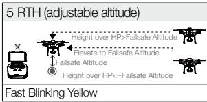
Failsafe RTH
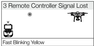
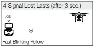
The Forward Vision System allows the aircraft to create a real-time map of its flight route as it flies. If the Home Point was successfully recorded and the compass is functioning normally, Failsafe RTH will be automatically activated if the remote controller signal is lost for more than three seconds. The aircraft will plan its return route and retrace its original flight route home. During RTH, if the remote controller signal is recovered, users can control the aircraft altitude and speed. Press the RTH button once to cancel RTH.
Failsafe Illustration
Smart RTH
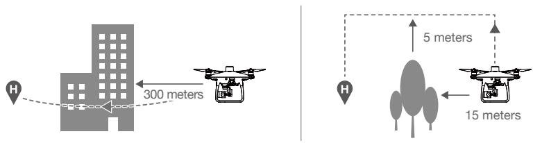
Use the RTH button on the remote controller when GNSS is available to initiate Smart RTH. The aircraft will then automatically return to the last recorded Home Point. Use the remote controller to control the aircraft's speed or altitude to avoid a collision during the Smart RTH process. As the aircraft returns, it will use the primary camera to identify obstacles as far as 300m in front, allowing it to plan a safe route home. Press and hold the Smart RTH button once to start the process, and press the Smart RTH button again to terminate the procedure and regain full control of the aircraft.
Low Battery RTH
The low battery level failsafe is triggered when the DJI Intelligent Flight Battery is depleted to a point that may affect the safe return of the aircraft. The user can cancel the RTH procedure by pressing the RTH button on the remote controller. The thresholds for these warnings are automatically determined based on the aircraft's current altitude and distance from the Home Point. The Low Battery RTH will only be triggered once during the same flight.
The aircraft will land automatically if the current battery level can only support the aircraft long enough to descend from its current altitude. The user cannot cancel the auto landing but can use the remote controller to alter the aircraft's orientation during the landing process.
The Battery Level Indicator is displayed in the DJI GS RTK app, and is described below:
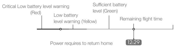
flowchart
graph LR
    A["Critical Low battery level warning (Red)"] --> B["Power requires to return home"]
    C["Low battery level warning (Yellow)"] --> B
    D["Sufficient battery level (Green)"] --> B
    E["Remaining flight time"] --> F["12:29"]
Battery level Indicator
| Battery Level Warning | Remark | Aircraft Status Indicator | DJI GS RTK App | Flight Instructions |
| Low battery level warning | Battery power is low. Fly the aircraft back. | Aircraft status indicator blinks RED slowly. | N/A | The aircraft will return to the Home Point automatically and hover at 2 meters above the Home Point. Users can also cancel the RTH process and land manually. Note: The Low Battery Level Warning will not prompt after users cancel RTH and regain control. |
| Critical Low battery level warning | The aircraft must land immediately. | Aircraft status indicator blinks RED quickly. | The DJI GS RTK app display will flash red and the aircraft will start to descend. The remote controller will sound an alarm. | Allow the aircraft to descend and land automatically. |
| Estimated remaining flight time | Estimated remaining flight based on current battery level. | N/A | N/A | N/A |

- When the Critical low battery level warning is triggered and the aircraft begins to land automatically, push the left stick upward to make the aircraft hover at its current altitude, giving you an opportunity to navigate to a more appropriate landing location.
- The colored zones and markers on the battery level indicator bar reflect the estimated remaining flight time. They are automatically adjusted according to the aircraft's current location and status.
- The Low Battery Warning threshold set in the Aircraft Battery settings page in the app is only for an alert and will not trigger RTH.
Precision Landing
The aircraft automatically scans and attempts to match the terrain features underneath during Return to Home. When current terrain matches home point terrain, the aircraft will start landing immediately to achieve precision landing.

- Landing Protection is active during precision landing.
- Precision Landing performance is subject to the following conditions:
a) Home point is recorded upon take off, and cannot not be refreshed during flight.
b) Aircraft must take off vertically. Take off altitude must be greater than 7 meters.
c) Home point terrain features remain largely unchanged.
d) Home point terrain with no distinctive features will affect the performance.
e) Lighting conditions cannot be too light nor too dark.
- The following actions are available during landing:
a) Pull throttle down to accelerate landing.
b) Moving the control sticks in any other direction will stop Precision Landing. The aircraft will descend vertically and Landing Protection will remain active.
RTH Safety Notices
 | The aircraft cannot avoid obstruction during RTH when the Forward Vision System is disabled. Users can use the remote controller to control aircraft altitude and speed. It is important to set a suitable Failsafe altitude before each flight. Launch the DJI GS RTK app, tap ••• and tap ✕ to set the Failsafe Altitude. |
 | If the aircraft is flying under 65 feet (20 meters) and RTH (including Smart RTH, Low Battery RTH and Failsafe RTH) is triggered, the aircraft will first automatically ascend to 65 feet (20 meters) from the current altitude. You can only cancel the ascending by exiting the RTH. |
 | The aircraft will automatically descend and land if RTH is triggered when the aircraft flies within a 16-feet (5 meters) radius of the Home Point and when the aircraft altitude is under 98 feet (30 meters), or if the obstacle sensing function is disabled. The aircraft will not ascend, and will land immediately at the current location. |
 | Aircraft cannot return to the Home Point when GNSS signal is weak ([ ⚙ ,| | ] displays grey) or the module is unavailable. |
 | If you move the throttle stick after the aircraft rises above 65 feet (20 meters) but below the pre-set Failsafe RTH altitude, the aircraft will stop ascending and immediately return to the Home Point. |
Obstacle Avoidance During RTH
Aircraft can now sense and actively attempt to avoid obstacles during RTH, provided that the lighting conditions are adequate for the Forward Vision System. Upon detecting an obstacle, the aircraft will act as follows:
- The aircraft will use the primary camera to identify obstacles as far as 984 feet (300 meters) in front, allowing it to plan a safe route home.
- The aircraft decelerates when an obstacle is sensed at 49 feet (15 meters) ahead.
- The aircraft stops and hovers then starts ascending vertically to avoid the obstacle. Eventually, the aircraft will stop climbing when it is at least 16 feet (5 meters) above the detected obstacle.
- Failsafe RTH procedure resumes, the aircraft will continue flying to the Home Point at the current altitude.

- The Obstacle Sensing function is disabled during RTH descent. Operate with care.
- To ensure the aircraft returns home forwards, it cannot rotate during RTH while the Forward Vision System is enabled.
- The aircraft cannot avoid obstacles above, beside, or behind the aircraft.
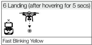
Landing Protection Function
Landing Protection will activate during auto landing.
- Landing Protection determines whether the ground is suitable for landing. If so, the aircraft will land gently.
- If Landing Protection determines that the ground is not suitable for landing, the aircraft will hover and wait for pilot confirmation. The aircraft will hover if it detects the ground is not appropriate for landing even with a critically low battery warning. Only when the battery level decreases to 0% will the aircraft land. Users retain control of aircraft flight orientation.
- If Landing Protection is inactive, the DJI GS RTK app will display a landing prompt when the aircraft descends below 0.3 meters. Tap to confirm or pull down the control stick for 2 seconds to land when the environment is appropriate for landing.

- Landing Protection will not be active in the following circumstances:
a) When the user is controlling the pitch/roll/throttle sticks (Landing ground detection will re-activate when control sticks are not in use)
b) When the positioning system is not fully functional (e.g. drift position error)
c) When the Downward Vision System needs re-calibration
d) When light conditions are not sufficient for the Downward Vision System
- If an obstacle is within 1-meter of the aircraft, the aircraft will descend to 0.3m above the ground and hover. The aircraft will land upon with user confirmation.
Industrial Applications
The Phantom 4 RTK can be used for industrial applications including but not limited to, photogrammetry and power line inspections. Select Photogrammetry or Waypoint Flight, plan flight paths, set parameters, and then the aircraft will perform automated operations. Operation resumption and obstacle avoidance are available. Users can import images to the DJI PC GS Pro application or a third-party mapping software to composite highly accurate maps for different applications. KML/KMZ files can be imported into the DJI GS RTK app to help plan operations.
KML/KMZ File Import
To plan operations, insert the microSD card with the KML/KMZ files into the microSD card slot on the remote controller to import the files into DJI GS RTK. For files including polygons, users can view the data on the map and use it to plan flight areas. For files including line strings, users can only view the data on the map, but cannot use it for planning.
Preparing Files
- Create a folder named "DJI" in the root directory of the microSD card. Then create a folder named "KML" under this folder. (The letters are not case sensitive.)
- Store the KML/KMZ files into the "KML" folder created above.
Importing Files
- Insert the microSD card into the microSD card slot on the remote controller. There will be a pop-up window on the main screen in the DJI GS RTK app then. If not, tap ≡, then tap 🔊.
- Tap the file in the window to select it. To delete the file, swipe to the left and tap 📄. Select files and then tap to import the files. Wait until the app indicates successful import.
Viewing Files
-
Go DJI GS RTK main screen > ≡ > ☑, select KML Files in the drop-down menu on the top to view the files. They are sort by time. KML file names displayed in the app are the original names of the files. KMZ files will be named in sequence: doc, doc(1), doc(2), etc.
-
Tap the icon on the right of each file to enter Map View and view the data on the map.

Users can also tap ☑ on the left in Camera View or Map View, and then select KML File in the drop-down menu to enter the file list page.
- Tap Edit to edit the waypoints for photogrammetry operation planning if the waypoint number is fewer than 125. Refer to the Photogrammetry section below for details on operation planning. If the waypoint number is more than 125, users have to reimport KML/KMZ files that meet the requirements.
Photogrammetry
After the operation area has been set, and settings have been configured, the DJI GS RTK app produces a flight route based on the user's input. After planning, the aircraft can carry out automated operations following the flight route. There are two types of Photogrammetry operations: 2D and 3D. The 2D flight route is s-shaped and can be used for 2D mapping. The 3D flight route consists of s-shaped routes that are crisscrossed to create 3D maps. The default values of the gimbal pitch angle for the two types are different.
Planning a Flight Route
-
Add edge points of the operation area through the two methods below:
-
View the imported KML/KMZ file, and then tap Edit. The vertices of the polygon in the file will be converted to the edge points of the operation area.
-
Go to the main screen in the DJI GS RTK app, tap Plan, and select Photogrammetry to enter Planning View. Then tap on the map to add edge points.
-
Edit edge points
Move: Drag the point to move.
Fine Tuning: Tap the point to show Fine Tuning buttons. Tap to adjust.
Delete: Tap twice to delete a point.
- Settings: After points are added, there will be a settings list on the right screen. Configure the settings and the app will produce a corresponding flight route.
- Adjust the route direction: Tap and drag the ⓞ icon near the route to adjust the flight direction of the produced route.
- Tap Save, name the operation, and then tap OK.
Performing Operations
An operation can be performed directly after planning. Follow the instructions below if the operation was not used immediately.
- Power on the remote controller, and then power on the aircraft.
- Go to the main screen in the DJI GS RTK app, and then tap Fly.
- Tap in the Camera View for camera settings. Tap on the left, select Plan in the drop-down menu, and then select an operation area. Tap the map to enter Edit Status to edit the edge points and adjust operation settings, and then save.
- Tap Invoke, and then tap Start. Wait for the flight route uploaded to the aircraft.
- Takeoff and perform the operation.
① If you fly the aircraft manually, slide to start the operation.
② If the aircraft is on the ground, slide to takeoff and start the operation.
Waypoint Flight
Fly the aircraft to desired positions, add waypoints and configure settings and actions for each waypoint. The waypoints will produce a flight route in sequence. After the operation is started, the aircraft will fly alongside the route and perform pre-set actions at each waypoint.
Planning Route
- Go to the main screen in the DJI GS RTK app, tap Plan, and select Waypoint Flight to enter Planning View.
- Fly the aircraft to the desired position, and short press the C2 Button on the remote controller once to add a waypoint.

The position of the added waypoints cannot be adjusted. Users can edit the waypoint for other configurations. See details below.
3. Edit waypoints
Tap the added waypoint on the map and there will be a settings list on the screen. Tap < / > to switch among the waypoints to edit each waypoint.
Altitude: The relative altitude between the aircraft and the Home Point at the selected waypoint. The aircraft will ascend or descend gradually to the altitude pre-set at the next waypoint if the values at the two consecutive waypoints are different. Tap the button, and then slide up or down anywhere on the screen to adjust the value.
Heading: The aircraft heading at the selected waypoint. North is 0^ , with a positive value indicating clockwise and a negative value indicating counter clockwise. The aircraft will rotate gradually to the heading pre-set at the next waypoint if the values at the two consecutive waypoints are different. Tap the button, and then slide up or down anywhere on the screen to adjust the value.
Pitch: The gimbal pitch angle at the selected waypoint. Pitch angle can range from -90^ to 0^ , with downward represented by -90^ and forward represented by 0^ . The gimbal will tilt to the angle pre-set after reaching the selected waypoint. Tap the button, and then slide up or down anywhere on the screen to adjust the value.
Action: Waypoint actions include: single shot, 3 continuous shots and none.
☐ : Tap to delete the selected waypoint.

Users cannot add waypoints during Edit Mode. Waypoints can be added after tapping Save or Cancel in the settings list.
- Route settings: After waypoints are added, tap the route settings button on the lower right corner to set an ending action for a task, action for when RC signal is lost, aircraft heading, cruising speed, and route recording. (Note that if route recording is enabled, shooting actions set for all the waypoints will be disabled, and the raw satellite observations will not be recorded.) Close the menu after configuration.
- Tap Save, name the operation, and then tap OK.
Performing Operations
An operation can be performed directly after planning. Follow the instructions below if the operation was not used immediately.
- Power on the remote controller, and then power on the aircraft.
-
Go to the main screen in the DJI GS RTK app, and then tap Fly.
-
Tap in the Camera View for camera settings. Tap on the left, select Plan in the drop-down menu, and then select an operation route. Tap the map to enter Edit Status to edit the waypoints and adjust operation settings, and then save.
-
Tap Invoke, and then tap Start. Wait for the flight route uploaded to the aircraft.
-
Takeoff and perform the operation.
① If you fly the aircraft manually, slide to start the operation.
② If the aircraft is on the ground, slide to takeoff and start the operation.
Operation Safety Notices

- Only take off in open areas.
- The operation will be automatically cancelled if the motors are started before beginning the operation. You will need to recall the operation in the operation list.
- During a Photogrammetry operation, the aircraft heading will follow the flight route. However, users can control the heading (not recommended), and fly forward or backward using the control sticks.
- During a Waypoint Flight operation, the aircraft heading can be set to follow the flight route or the customized angle pre-set for each waypoint in Route Settings. However, users cannot control the heading with the control stick, but they can control the direction of flight (forward or backward).
- During the operation, tap Pause on the screen and the aircraft will hover. Users can fly the aircraft forward or backward along the flight route. Tap Resume and the operation will resume from the current position.
- An operation can be paused by toggling the Pause switch. The aircraft will hover and record the breakpoint, and then the aircraft can be controlled manually. To continue the operation, select it from the list again and then resume. The aircraft will automatically return to the breakpoint and resume the operation.
- The aircraft will hover at the end point automatically once the operation is complete. Instead of RTH, the aircraft can also be set to perform other flight actions within the app.
Operation Resumption
When exiting an operation, the aircraft will record a breakpoint. The Operation Resumption function allows you to pause an operation temporarily (e.g., to change battery, and avoid obstacles manually) and then resume operation at the breakpoint.
Recording a Breakpoint
Exit an operation through one of the following methods and the aircraft will record its location as a breakpoint if GNSS signal is strong:
- Tap the End button on the lower right corner of the screen.
- Initialize the RTH procedure.
- Toggle the Pause switch.
- If the GNSS signal is weak, the aircraft enters Attitude mode and exits the current operation. The last position where there was a strong GNSS signal is recorded as a breakpoint.

- Ensure that GNSS signal is strong when using the Operation Resumption function. Otherwise, the aircraft cannot record and return to the breakpoint.
- The breakpoint is updated as long as it meets one of the above conditions.
Resuming Operation
- Exit an operation through one of the above methods. The aircraft will record the current location as the breakpoint.
- The aircraft will end the current operation and record the operation progress. Users can control the aircraft manually.
- Select the operation in the Executing tag of the operation list again. The aircraft will automatically return to the breakpoint and resume the operation.
System Data Protection
During an operation, the System Data Protection feature enables the DJI GS RTK app to retain vital system data (e.g. operation progress, breakpoint) after the aircraft is powered off for battery replacement. Follow the instructions in Operation Resumption to resume the operation after restarting the aircraft.
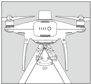
Vision System and Infrared Sensing System
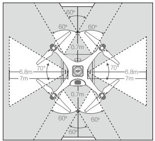
The main components of the Vision System are located on the front, rear and bottom of the aircraft, including [1] [2] [4] three stereo vision sensors and [3] two ultrasonic sensors. The Vision System uses ultrasound and image data to help the aircraft maintain its current position, enabling precision hovering indoors or in environments where a GNSS signal is not available. The Vision System constantly scans for obstacles, allowing the aircraft to avoid them by going over, around, or hovering.
The Infrared Sensing System consists [5] of two 3D infrared modules on both sides of the aircraft. These scan for obstacles on both sides of the aircraft and is active in certain flight modes.
![[1] [2] [3] PHANTOM [5] [4]](/content/2026/01/221891/images/e3598be0fda47dcd2639ffbf78b0fdf57a597773e6d3865403ed984ef875bcf9.jpg)
Detection Range
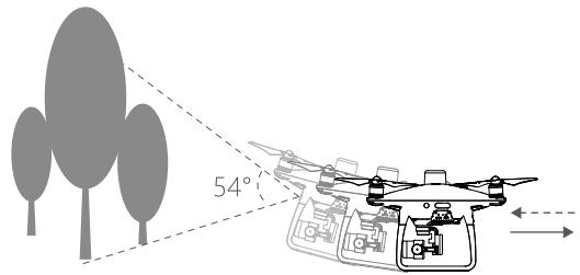
The detection range of the Vision System and Infrared Sensing System are depicted as follow. Note that the aircraft cannot sense and avoid the obstacles that are not within the detection range.
natural_image
Diagram of a quadcopter drone with 50-degree angle markings and no text or symbols present
In P-mode, both the forward and the rear Vision Systems work if the speed is within 13mph (22kph). At higher speeds, only the vision system facing the direction of travel is active.
Calibrating Sensors
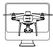
Vision Systems cameras installed on the aircraft are calibrated on delivery. However these cameras are vulnerable to excessive impact and will require occasional calibration via DJI Assistant 2 for Phantom. Follow the steps below to calibrate the sensors.
natural_image
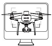
Line drawing of a quadcopter drone mounted on a computer monitor (no text or symbols)01 pint the aircraft toward the screen
natural_image
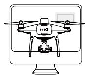
Line drawing of a quadcopter drone mounted on a computer monitor (no text or symbols)02 Align the boxes
natural_image
Illustration of a drone on a computer monitor (no text or symbols)03 Pan and tilt the aircraft
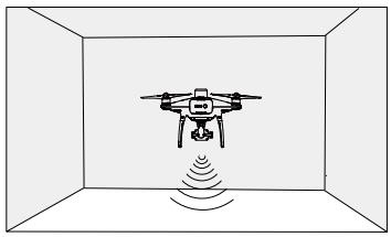
Using Vision Positioning
Vision Positioning is activated automatically when the aircraft is turned on. No further action is required. Vision Positioning is typically used in indoor environments, where GNSS is unavailable. Using the sensors that are built into the Vision System, the aircraft can hover precisely even without GNSS. The Downward Vision System works best when the aircraft is at altitudes of under 33 ft (10 m). Operate the aircraft with great caution when flying at high speeds at low altitudes (under 0.5 m).
natural_image
Diagram of a drone inside a transparent enclosure with signal waves (no text or symbols)Follow the steps below to use Vision Positioning:
- Turn on the aircraft. The aircraft status indicator will flash green two times, which indicates the Vision Positioning is ready.
- Gently push the left stick up to lift off and the aircraft will hover in place.
Assisted Braking from Obstacle Sensing
Powered by the Obstacle Sensing, the aircraft will now be able to actively brake when obstacles are detected around the aircraft. Note that Obstacle Sensing function works best when lighting is adequate and the obstacle is clearly marked or textured. The aircraft must fly at no more than 31mph (50kph) to allow sufficient braking distance.

- The 3D Infrared Sensing System is only active in Beginner mode* and Tripod mode*. Fly with caution.
- The performance of your Vision System and Infrared Sensing System are affected by the surface being flown over. Ultrasonic sensors may not be able to accurately measure distances when operating above sound-absorbing materials and the camera may not function correctly in suboptimal environments. The aircraft will switch from P-mode to A-mode automatically if neither vision sensors nor ultrasonic sensors and Infrared Sensing System are available. Operate the aircraft with great caution in the following situations:
a) Flying over monochrome surfaces (e.g. pure black, pure white, pure red, pure green).
b) Flying over a highly reflective surfaces.
c) Flying at high speeds of over 31mph (50kph) at 2 meters or over 11mph (18kph) at 1 meter.
d) Flying over water or transparent surfaces.
e) Flying over moving surfaces or objects.
f) Flying in an area where the lighting changes frequently or drastically.
g) Flying over extremely dark (lux < 10) or bright (lux > 100,000) surfaces.
h) Flying over surfaces that can absorb sound waves (e.g. thick carpet).
i) Flying over surfaces without clear patterns or texture.
j) Flying over surfaces with identical repeating patterns or textures (e.g. tiling).
k) Flying over inclined surfaces that will deflect sound waves away from the aircraft.
I) Flying over obstacles with too small effective infrared reflective surface.
m) DO NOT position the sides of two aircraft toward each other to avoid interference between the 3D infrared modules.
n) DO NOT cover the protective glass of the infrared module. Keep it clean and undamaged.
o) Flying at high speed at low altitude (under 0.5 m).

- Keep sensors clean at all times. Dirt or other debris may adversely affect their effectiveness.
- Vision Positioning is only effective when the aircraft is at altitudes of 0.3 to 10 meters.
- The Vision Positioning may not function properly when the aircraft is flying over water.
- The Vision System may not be able to recognize pattern on the ground in low light conditions (less than 100 lux).
- Do not use other ultrasonic devices with frequency of 40kHz when Vision System is in operation.
RTK Functions
The Phantom 4 RTK has a built-in DJI Onboard D-RTK, which provides more accurate data for centimeter-level positioning to improve operation precision when using with the DJI D-RTK 2 High-Precision GNSS Mobile Station or Network RTK service. The onboard D-RTK, providing precision position and speed information combined with optimized algorithms, is more accurate than a standard compass sensor and functions even with magnetic interference from metal structures, ensuring stable flight. If the RTK signal is weak and differential data cannot be transmitted during a Photogrammetry or Waypoint Flight operation, users can read the raw satellite observations* recorded in the microSD card in the aircraft after the flight, and then use PPK technology to achieve centimeter-level positioning.
Enable/Disable RTK
Ensure that the “RTK Function” is enabled and RTK service type is correctly set (D-RTK 2 Mobile Station or Network RTK service) before each use. Go to Camera View in the DJI GS RTK app > ⋯ > RTK to view and set.
Make sure to disable RTK function if not in use. Otherwise, the aircraft will not be able to take off when there is no differential data.
Using with the DJI D-RTK 2 Mobile Station
- Refer to the D-RTK 2 Mobile Station User Guide to complete linking between the aircraft and the mobile station and setup of the mobile station.
- Power on the mobile station and wait for the system to start searching for satellites. The RTK status icon on top of the Camera View in the DJI GS RTK app will show _u to indicate that the aircraft has obtained and used the differential data from the mobile station.

After enabling the RTK function and connecting to a data source, be sure to wait for the aircraft's RTK module to finish initializing and the RTK / GNSS signal strength icon in the app shows FIX so that the aircraft can take off.
Using with the Network RTK Service
The Network RTK service uses the remote controller instead of the base station to connect to an approved Network RTK server for differential data. Keep the remote controller on and connected to the Internet when using this function.
- Ensure that the remote controller is connected to the aircraft and has access to the Internet.
- Go to Camera View in the DJI GS RTK app > ••• > RTK, select the RTK service type to custom network RTK, and then input the network information.
- Wait for the remote controller to be connected with the Network RTK server. The RTK status icon on top of the Camera View in the DJI GS RTK app will show (t_A^p) to indicate that the aircraft has obtained and used the RTK data from the server.
* The raw satellite observations are stored in the same directory as the aerial photos. They will only be recorded during Photogrammetry or Waypoint Flight operations. For Waypoint Flight operations, route recording should be disabled in Route Settings. Otherwise, the raw satellite observations cannot be recorded. In other situations, such as flying the aircraft and shooting manually, the data will not be recorded.
Flight Recorder
Flight data is automatically recorded to the internal storage of the aircraft. To access this data, connect the aircraft to the PC through the Micro USB port and launch the DJI Assistant 2.
Attaching and Detaching the Propellers
Use only DJI approved propellers with your aircraft. The grey and black ring on the propeller indicate where they should be attached and in which direction whey should spin.
| Propellers | Silver Ring | Black Ring |
| Figure |  |  |
| Attach On | Motors without black dots | Motors with black dots |
| Legends | Lock: Turn the propellers in the indicated direction to mount and tighten.Unlock: Turn the propellers in the indicated direction to loosen and remove. | |
Attaching the Propellers
- Be sure to remove the warning stickers from the motors before attaching the propellers.
- Mount the propellers with black propeller rings to the motors with black dots. Mount the propellers with sliver propeller rings to the motors without black dots. Press the propeller down onto the mounting plate and rotate in the lock direction until it is secured in its position.
natural_image
Diagram showing a circular component labeled 'c' and a magnified view of a fan-like object with internal components (no text or symbols)
natural_image
Illustration of a hand holding a small object with a circular inset showing two numbered items (no text or symbols present)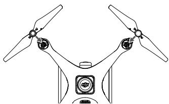
natural_image
Diagram of a drone's top and front propeller system (no text or symbols)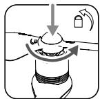
natural_image
Diagram of a mechanical or electrical component with directional arrows indicating motion (no text or symbols)Detaching the Propellers
Press the propellers down into the motor mount and rotate in the unlock direction.

- Be aware of the sharp edges of the propellers. Handle with care.
- Use only the DJI approved propellers. Do not mix propeller types.
- Check that the propellers and motors are installed correctly and firmly before every flight.
- Ensure that all propellers are in good condition before each flight. DO NOT use aged, chipped, or broken propellers.
- To avoid injury, STAND CLEAR of and DO NOT touch propellers or motors when they are spinning.
- ONLY use original DJI propellers for a better and safer flight experience.
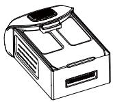
DJI Intelligent Flight Battery
The DJI Intelligent Flight Battery has a capacity of 5870 mAh, a voltage of 15.2 V, and a smart charge/discharge functionality. It should only be charged using an appropriate DJI approved power adapter and charging hub.
natural_image
Line drawing of a portable electronic device with ventilation slots and a lid (no text or symbols)Intelligent Flight Battery
natural_image
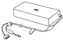
Line drawing of a rectangular electronic device with attached cables and connectors (no text or symbols)AC Power Adapter
natural_image
Isometric line drawing of a rectangular electronic device with internal compartments (no text or symbols)Charging Hub

- The Intelligent Flight Battery must be fully charged before using it for the first time.
- Never insert or remove the battery when it is turned on.
- Ensure the battery is mounted firmly. The aircraft will not take off if the battery is mounted incorrectly.
DJI Intelligent Flight Battery Functions
- Battery Level Display: The LED indicators display the current battery level.
- Auto-Discharging Function: To prevent swelling, the battery automatically discharges to below 65% of total power when it is idle for more than ten days. It takes around two days to discharge the battery to 65%. It is normal to feel moderate heat being emitted from the battery during the discharge process.
- Balanced Charging: Automatically balances the voltage of each battery cell when charging.
- Overcharge Protection: Charging automatically stops when the battery is fully charged.
- Temperature Detection: The battery will only charge when the temperature is between 5^ C ( 41^ F) and 40^ C ( 104^ F).
- Over Current Protection: The battery stops charging when a high amperage (more than 8 A) is detected.
- Over Discharge Protection: To prevent over-discharge damage, discharging automatically stops when the battery voltage reaches 12 V.
- Short Circuit Protection: Automatically cuts the power supply when a short circuit is detected.
- Battery Cell Damage Protection: The DJI GS RTK app displays a warning message when a damaged battery cell is detected.
- Sleep Mode: To save power, the battery enter sleep mode after 20 minutes of inactivity.
- Communication: Information pertaining to the battery's voltage, capacity, current, etc. is transmitted to the aircraft's main controller.

Refer to Phantom 4 Series Intelligent Flight Battery Safety Guidelines before use. Users take full responsibility for all operations and usage.
Using the Battery
Turning ON/OFF
Turning On: Press the Power Button once, then press again and hold for 2 seconds to turn on. The Power LED will turn green and the Battery Level Indicators will display the current battery level.
Turning Off: Press the Power Button once, then press again and hold for 2 seconds to turn off. The battery power LED will flash when powering off the Phantom to allow automatically stopping of a recording during the event recording wasn't stopped.
Low Temperature Notice:
- Battery capacity is significantly reduced when flying in low temperature ( < 0^ ) environments.
- It is not recommended that the battery be used in extremely low temperature (< -10°C) environments. Battery voltage should reach the appropriate level when operating environment with temperatures between -10°C and 5°C.
- End the flight as soon as the DJI GS RTK app displays the “Low Battery Level Warning” in low temperature environments.
- Keep the battery indoors to warm it before flying in low temperature environments.
- To ensure optimal performance of the battery, keep the battery temperature above 20^ C.
- The charger will stop charging the battery if the battery cell's temperature is not within the operating range (0°C \~ 40°C).

In cold environments, insert the battery into the battery compartment and turn on the aircraft for approximately 1-2 minutes to warm up before taking off.
Checking the Battery Level
The Battery Level Indicators display how much power remains. When the battery is turned off, press the Power Button once. The Battery Level Indicators will light up to display the current battery level. See below for details.

The Battery Level Indicators will also show the current battery level during charging and discharging. The indicators are defined below.
☐ : LED is on.
: LED is flashing.
☐ : LED is off.
Battery Level Indicators
| LED1 | LED2 | LED3 | LED4 | Battery Level |
| 87.5%~100% | ||||
| 75%~87.5% | ||||
| 62.5%~75% | ||||
| 50%~62.5% | ||||
| 37.5%~50% | ||||
| 25%~37.5% | ||||
| 12.5%~25% | ||||
| 0%~12.5% | ||||
| =0% |
Charging the Intelligent Flight Battery

- Air cool the Intelligent Flight Battery after each flight. Allow its temperature to drop to room temperature before charging.
- The charging temperature range is 5^ to 40^ . The battery management system will stop the battery from charging when the battery cell temperature is out of range.
- Always turn off the battery before inserting it or removing it from the aircraft. Never insert or remove a battery when it is turned on.
Using only the Power Adapter for Charging
- Connect the AC power adapter to a power source (100-240 V 50/60 Hz).
- Connect the Intelligent Flight Battery to the power adapter to start charging. If the battery level is above 95%, turn on the battery before charging.
- The Battery Level Indicator will display the current battery level as it is charging.
- The Intelligent Flight Battery is fully charged when the Battery Level Indicators are all off.
flowchart
graph LR
    A["Input"] --> B["AC Power Adapter"]
    B --> C["Power Outlet"]
    style A fill:#f9f,stroke:#333
    style C fill:#ccf,stroke:#333
Intelligent Flight Battery
Battery Level Indicators While Charging
| LED1 | LED2 | LED3 | LED4 | Battery Level |
| 0%~25% | ||||
| 25%~50% | ||||
| 50%~75% | ||||
| 75%~100% | ||||
| Fully Charged |
Using the Power Adapter and Charging Hub for Charging
1. Connecting to a Power Source
Connect the power adapter to a power outlet (100-240V, 50/60Hz), then connect the charging bub to the power adapter.
flowchart
graph LR
    A["Charging Hub"] --> B["AC Power Adapter"]
    B --> C["Power Outlet"]
    B --> D["Ground"]
2. Connecting Batteries
Charging Mode:
Align the grooves on the Intelligent Flight Battery with the battery slot tracks to insert the battery and begin charging. The Intelligent Flight Battery with the highest power level will be charged first. Other batteries will be charged in sequence according to their power levels.
If the Status LED Indicator of the charging hub is solid green and the LED lights on the Intelligent Flight Battery turn off, charging is complete and the Intelligent Flight Battery can be disconnected from the charging hub.
Storage Mode:
The charging hub will discharge batteries with more than 50% power to reduce the charge to 50%. Meanwhile batteries with less than 50% charge will be charged to 50%.
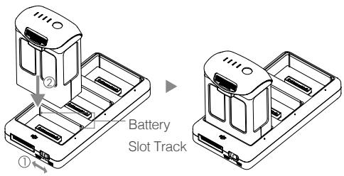

- Be sure to align the grooves on the Intelligent Flight Battery with the battery slot tracks. The Status LED Indicator will turn solid yellow if the battery is properly inserted.
- In storage mode, you can power on the Intelligent Flight Batteries to discharge them without having to connect to a power source if all batteries have more than 50% power.
Status LED Indicator Description
| Status LED Indicator | Description | |
| Charging Mode | ||
| Y — | Solid Yellow | Queuing to charge |
| G ...... | Blinking Green | Charging |
| G — | Solid Green | Fully charged |
| R — | Solid Red | No battery detected |
| RRR ---- | All Blinking Red | Power supply error, please check the connection to the Battery Charger |
| Storage Mode | ||
| Y — | Solid Yellow | Ready to charge or discharge |
| B ...... | Blinking Blue | Charging or discharging |
| G — | Solid Blue | The battery’s power level is 50% |
| R — | Solid Red | No battery detected |
| RRR ---- | All Blinking Red | Power supply error, please check the connection to the Battery Charger |
Battery Protection LED Display
The table below shows battery protection mechanisms and corresponding LED patterns.
| Battery Level Indicators while Charging | |||||
| LED1 | LED2 | LED3 | LED4 | Blinking Pattern | Battery Protection Item |
| LED2 blinks twice per second | Over current detected | ||||
| LED2 blinks three times per second | Short circuit detected | ||||
| LED3 blinks twice per second | Over charge detected | ||||
| LED3 blinks three times per second | Over-voltage charger detected | ||||
| LED4 blinks twice per second | Charging temperature is too low | ||||
| LED4 blinks three times per second | Charging temperature is too high | ||||
After these issues are resolved, press the Power Button to turn off the Battery Level Indicator. Unplug the Intelligent Flight Battery from the charger and plug it back in to resume charging. Note that you do not need to unplug and plug in the charger in the event of a room temperature error; the charger will resume charging when the temperature is within the allowable range.

- DJI does not take any responsibility for damage caused by third-party chargers.
- If the battery level is above 95% , turn on the battery before charging.

How to discharge your Intelligent Flight Battery:
Place the Intelligent Flight Battery into the battery compartment and turn it on. Fly the aircraft out doors until the battery level is low (such as 20% of power left).
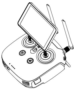
Remote Controller
This section describes the features of the remote controller and includes instructions for controlling the aircraft and the camera.
natural_image
Line drawing of a drone's internal control panel with multiple motors and a handheld device (no text or symbols)Remote Controller
Profile
The Phantom 4 RTK remote controller has a transmission range of up to 4.3 mi / 7 km (FCC-compliant version) with controls for camera tilt and photo capture. Built into the remote controller is the latest DJI OcuSync to enhance anti-interference ability for more stable and smoother video downlink. The remote controller includes a 5.5-inch high luminance monitor with integrated DJI GS RTK app for HD display. Users can plan flight paths and perform both Photogrammetry and Waypoint Flight operations in the app. The remote controller's Multi-Aircraft Control mode can be used to coordinate the operation of up to five aircraft at the same time, enabling pilots to work more efficiently.

- Compliance Version: The remote controller is compliant with local compliance and regulations.
- Stick Mode: Control can be set to Mode 1 or Mode 2, or to a custom mode.
- Mode 1: The right stick serves as the throttle.
- Mode 2: The left stick serves as the throttle.
Using the Remote Controller
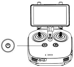
Turning the Remote Controller On and Off
The remote controller uses a removable, interchangeable Intelligent Battery. The battery level is indicated via the Battery Level LEDs on the front panel after the battery is mounted. Follow the steps below to turn on your remote controller:
- When the remote controller is turned off, press the Power button once to check the current battery level, indicated by the Battery Level LEDs. If the battery level is too low, recharge before use.
- Press the Power button once. Then press and hold to turn on the remote controller.
- The remote controller will beep when turned on. The Status LED will rapidly blink green, indicating that the remote controller is linking to the aircraft. They will glow solid green when linking is complete.
- Repeat Step 2 to turn off the remote controller.
natural_image
Line drawing of a digital control device with multiple rotary knobs and a power button (no text or symbols)
The remote controller internal backup battery allows users to insert and remove the external Intelligent Battery while the remote controller is still on and in use. The device will enter Sleep Mode to save power. Users are then required to replace the Intelligent Battery within three minutes, or the remote controller will power off.
Charging the Remote Controller
Charge the remote controller Intelligent Battery using the included AC power adapter and Charging Hub.
- Place the battery into the Charging Hub, connect the AC power adapter to the Charging Hub, and then connect the charger to a power outlet (100-240V, 50/60Hz).
- The Charging Hub will intelligently charge batteries in sequence according to battery power levels from high to low.
- The Status LED blinks green when charging and turns solid green when fully charged. The buzzer will begin beeping when charging is complete. Remove the battery or turn off the buzzer to stop it.
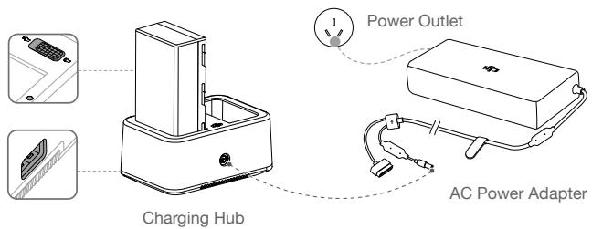

DO NOT charge the Intelligent Flight Battery together with the Intelligent Battery.

USB power supply port can be used to charge the mobile device of 5V/2A.
| Status LED | Description | |
| G | ...... Blinks Green | Charging |
| G | — Solid Green | Fully charged |
| R | ...... Blinks Red | Battery Charger Error. Retry with an official battery charger. |
| R | — Solid Red | Battery error |
| Y | ...... Blinks Yellow | Battery temperature too high/low. Temperature must be within operating range (5°-40°C) |
| Y | — Solid Yellow | Ready to charge |
| HWE | ...... Alternating Green Blinks | Intelligent Battery not detected |
Controlling the Camera
Shoot videos/photos, and adjust gimbal pitch angle via the Shutter Button, Record Button, and Gimbal Dial on the remote controller.
- Gimbal Dial
Control the tilt of the gimbal. Turn left to tilt the gimbal upward and right to tilt the gimbal downward.
- Video Recording Button
Press once to start recording video, then press again to stop recording.
- Shutter Button
Press to take a photo.
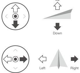
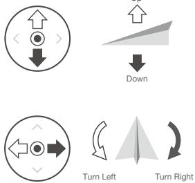
Controlling the Aircraft
This section explains how to control the orientation of the aircraft through the remote controller. Control can be set to Mode 1, Mode 2 or Mode 3, or to a custom mode.
Mode 1
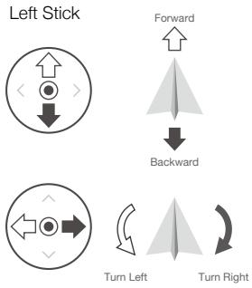
flowchart
graph TD
    A["Left Stick"] --> B["Forward"]
    B --> C["Backward"]
    D["Turn Left"] --> E["Turn Right"]
Right Stick
Mode 2
Left Stick
Right Stick
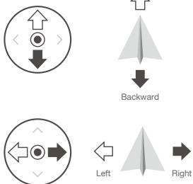
flowchart
graph TD
    A["Up/Down Arrow"] --> B["Backward"]
    C["Left Arrow"] --> D["Right Arrow"]
Mode 3
Left Stick
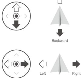
flowchart
graph TD
    A["Up/Down"] --> B["Left"]
    C["Right"] --> D["Backward"]
Right Stick
The Remote Control is set to Mode 2 by default.

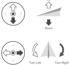
Stick Neutral/Mid-Point: Control sticks are in the center position.
Moving the Control Stick: The control stick is pushed away from the center position.
| Remote Controller (Mode 2) | Aircraft( Indicates Nose Direction) | Remarks |
 |  | Moving the left stick up and down changes the aircraft's elevation.Push the stick up to ascend and down to descend. When both sticks are centered, the aircraft will hover in place.The more the stick is pushed away from the center position, the faster the aircraft will change elevation. Always push the stick gently to prevent sudden and unexpected elevation changes. |
 |  | Moving the left stick to the left or right controls the rudder and rotation of the aircraft.Push the stick left to rotate the aircraft counterclockwise, push the stick right to rotate the aircraft clockwise. If the stick is centered, the aircraft will maintain its current orientation.The more the stick is pushed away from the center position, the faster the aircraft will rotate. |
 |  | Moving the right stick up and down changes the aircraft's forward and backward pitch.Push the stick up to fly forward and down to fly backward. The aircraft will hover in place if the stick is centered.Push the stick further away from the center position for a larger pitch angle (maximum 30°) and faster flight. |
 |  | Moving the right stick control left and right changes the aircraft's left and right pitch.Push left to fly left and right to fly right. The aircraft will hover in place if the stick is centered. |
 |  | During an automatic flight, toggle the Pause Switch to exit from the automatic flight. The aircraft will hover at the current position. |
Adjusting Controller Sticks
Hold and twist the controller sticks clockwise or counter clockwise to adjust the length of the controller sticks. A proper length of controller sticks can improve the controlling accuracy.
natural_image
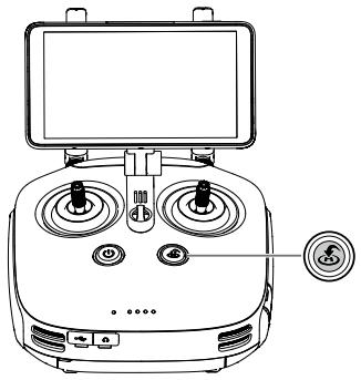
Diagram of a mechanical or electrical setup with a central device and rotating components (no text or symbols visible)RTH Button
Press and hold the RTH button to start the Return to Home (RTH) procedure. The LED ring around the RTH Button will blink white to indicate that the aircraft is entering RTH mode. The aircraft will then return to the last recorded Home Point. Press this button again to cancel the RTH procedure and regain control of the aircraft.
natural_image
Line drawing of a remote control device with dual switches and a monitor (no text or symbols)Optimal Transmission Range
The transmission signal between the aircraft and the remote controller is most reliable within the area that depicted below:

Ensure that the aircraft is flying within the optimal transmission zone. To achieve the best transmission performance, maintain the appropriate relationship between the operator and the aircraft.
Remote Controller Status LED
The Status LED reflects the strength of the connection between the remote controller and the aircraft. The RTH LED indicates the RTH status of the aircraft. The table below contains more information about these indicators.
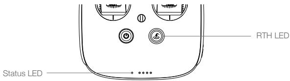
| Status LED | Alarm | Remote Controller Status |
| R — Solid Red | ♪ Chime | The remote controller is disconnected from the aircraft. |
| G — Solid Green | ♪ Chime | The remote controller is connected to the aircraft. |
| R ...... Slow Blinking Red | D-D-D...... | Remote controller error. |
| RG/RY ...... | ||
| Red and Green/ Red and Yellow Alternate Blinks | None | HD downlink is disrupted. |
| RTH LED | Sound | Remote Controller Status |
| W — Solid White | ♪ Chime | Aircraft is returning home. |
| W ...... Blinking White | D · · · | Sending RTH command to the aircraft. |
| W ...... Blinking White | DD · · · · · | RTH procedure in progress. |

The Remote Controller Status Indicator will blink red and sound an alert, when the battery level is critically low.
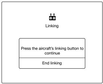
Linking the Remote Controlle
The remote controller is linked to your aircraft by default. Linking is only required when using a new remote controller for the first time. If using Multi-Aircraft Control function, linking all the aircraft to the same remote controller is required.
- Power on the remote controller and open the DJI GS RTK app. Power on the aircraft.
- Tap Fly to enter Camera View and tap ●●● > ☐. Select Aircraft as the linking device, tap Single Linking or Multi Linking (if Multi-Aircraft Control is in use), and then tap Pairing. The Status LED blinks blue and the remote controller sounds double beep repeatedly, indicating that the remote controller is ready for linking.
flowchart
graph TD
    A["Linking"] --> B["Press the aircraft's linking button to continue"]
    B --> C["End linking"]
- Press the Link button on the aircraft. Then release and wait for a few seconds.
- The Status and Link LED will glow solid green if linking is successful. If the Link LED does not glow solid green, linking failure occurred. Enter linking status again and retry.
- Repeat steps 3 and 4 to complete linking between all the aircraft (up to five) and the remote controller, if Multi Linking is selected. Then tap End linking.
Multi-Aircraft Control Function
The remote controller features Multi-Aircraft Control function which can be used to coordinate the operation of up to five aircraft at the same time, enabling pilots to work very efficiently. Turn the Aircraft Control Switch Dial on the remote controller to switch between different aircraft for single control of the desired aircraft.

When using the Multi-Aircraft Control function, to avoid interference among operation groups, do not operate more than three groups within a 50-meter radius. Unless using the Phantom 4 RTK with a DJI D-RTK 2 Mobile Station, it is necessary to manually configure each remote controller's serial number in the DJI GS RTK app.
Enter Multi-Aircraft Control Mode
- Link all the aircraft (up to five) to the same remote controller according to the steps in "Linking the Remote Controller".
- Close the settings menu after linking. The linked aircraft will be listed on the left of the screen sorted by number.
Switch Control
Users can switch control among different aircraft via the aircraft status box on the left screen in the app or the Aircraft Control Switch Dial on the remote controller. The Front LEDs of the selected aircraft will be solid red while the Front LEDs of other aircraft will be solid yellow.
Switch in the App
Tap the status box of the corresponding number in the app. The side of the box will turn blue and the Front LEDs of the aircraft will blink red quickly, indicating the corresponding aircraft has been selected.
Switch by the Dial
- Turn the Aircraft Control Switch Dial on the remote controller. There will be an arrow near the corresponding status box in the app, and the Front LEDs of the aircraft will blink yellow quickly, indicating the corresponding aircraft is in pre-selected status.
- Press the dial once. The side of the box in the app will turn blue and the Front LEDs of the aircraft will blink red quickly for a few seconds and then turn to solid red, indicating the corresponding aircraft has been selected.
Multi-Aircraft Operations
- Select the desired aircraft by switching control.
- Tap the status box of the selected aircraft, then tap ☑ on the left of the screen, or tap ▲ on top of the screen to select and use an operation in the Plan tag. Perform the operation after setting operation parameters. The selected flight routes data will be uploaded to the aircraft.
- Use an operation to each aircraft. Tap ☐ to show the status boxes of all the aircraft and tap another status box to switch to the corresponding aircraft.
- Tap Start after using operations for all the aircraft. Users can slide the sliders for each aircraft in the prompted window or slide the slider for all aircraft at the bottom position to take off all the aircraft and start operations at the same time.
- If there is any emergency during operation, toggle the Pause Switch on the remote controller to brake all the aircraft. Then all operations will be paused and the aircraft will hover in place and can be controlled manually. To continue the operation, users should use the operation again in Executing tag in icon.

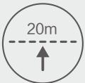
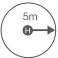
During multi-aircraft operations, aircraft will automatically avoid each other based on positioning information. When the distance between aircraft is 15 m, they will slow down, and when the distance is 5 m, the aircraft will not be able to get any closer to each other.
Exit from Multi-Aircraft Control Mode
Users can exit from the mode through the following three methods.
Method 1: Link the remote controller to the only one desired aircraft according to the previous instructions (Single-Machine Pairing should be selected).
Method 2: Delete other aircraft and remain the only one aircraft in the Linked Aircraft list. So the remote controller can control this aircraft only.
Method 3: Power off the other aircraft that don't need control and power on the only one desired aircraft. So the remote controller can control this aircraft only. Note: if power on the other aircraft again, the remote controller and the linked aircraft will enter Multi-Aircraft Control mode automatically. Exit from this mode completely through method 1 or 2 if needed.
Gimbal and Camera
This section provides the technical specifications of the camera and explains the gimbal's operation modes.
Gimbal and Camera
Camera
Profile
The Phantom 4 RTK camera uses a 1-inch CMOS sensor with effective pixels of 20 M and a 24 mm (35 mm format equivalent) wide-angle lens. It is equipped with a blue glass filter to deliver enhanced picture quality and a UV lens for additional protection. An ND filter can be used when the operating environment is too bright.
The Phantom 4 RTK supports the capture of 4K at 30fps and a maximum video bitrate of 100 Mbps.
The 20 megapixel photos taken by Phantom 4 RTK is the result of the application of advanced image processing technique. A mechanical shutter with a 1/2000 max speed eliminates rolling shutter distortion when capturing stills of fast moving objects.
Camera Micro SD Card Slot
To store your photos and videos, insert the microSD card into the slot as shown below before turning on the aircraft. The Phantom 4 RTK comes with a 16 GB microSD card and supports microSD cards up to 128 GB. A UHS-1 and above microSD card is recommended due to their fast read and write speeds that support high-resolution video data. Users can read the photos and videos, and the raw satellite observations during Photogrammetry and Waypoint Flight operations from the microSD card.
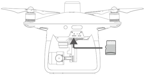
natural_image
Top-down line drawing of a drone's internal components, showing propeller, airbag, and control panel (no text or labels)
Do not remove the microSD card from the aircraft when it is shooting.

To ensure the stability of the camera system, single video recordings are capped at 30 minutes.
Micro USB Port
Turn on the aircraft and connect a Micro USB cable to the Micro USB Port to update firmware, read the photos and videos, and the raw satellite observations during Photogrammetry and Waypoint Flight operations.
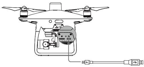
natural_image
Diagram of a drone with internal components and connected cables (no text or labels)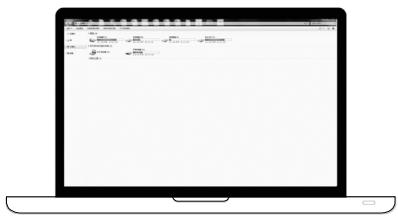
Camera Operation
Use the Shutter and Video Recording buttons on the remote controller or in the DJI GS RTK app to shoot the photos or videos.
Camera Status LED Indicator Descriptions
The Camera LED Indicator lights up after the flight battery is powered on. It provides information on the working status of the camera.
| Camera LED Indicator | Camera status | |
| G...... | Green Fast Blink | System is warming up |
| G— | Solid Green | The system is warmed up, the microSD card is inserted and working properly |
| G | Green Blink Once | Taking a single picture |
| R...... | Slow Red Blink | Recording |
| R...... | Fast Red Blink | microSD card error |
| R×2...... | Double Red Blink | Overheated Camera |
| R—— | Solid Red | System error |
| G R...... | Green and Red Blink | Firmware Upgrading |
Gimbal
Profile
The 3-axis gimbal provides a steady platform for the attached camera, allowing you to capture clear, stable images and video. Turn the dial to adjust the gimbal pitch angle.
Controllable range of the pitch angel is -90^ to +30^ . The default range is -90^ to 0^ . This can be adjusted in the DJI GS RTK app.
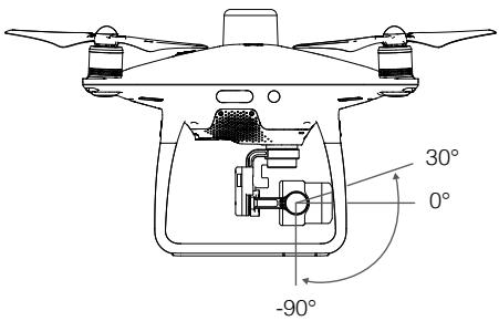
Gimbal Operation Modes
Two gimbal operation modes are available. Switch between the different operation modes on the gimbal settings page of the DJI GS RTK app. Refer to the table below for details:
| Follow Mode | The angle between the gimbal's orientation and aircraft's nose remains constant at all times. | |
| FPV Mode | The gimbal will synchronize with the movement of the aircraft to provide a first-person perspective flying experience. | |
| ⚠️ | A gimbal motor error may occur in these situations:(1) the aircraft is placed on uneven ground or the gimbal's motion is obstructed.(2) the gimbal has been subjected to an excessive external force, such as a collision. Please take off from flat, open ground and protect the gimbal at all times.Flying in heavy fog or clouds may make the gimbal wet, leading to temporary failure. The gimbal will recover full functionality after it dries.It is normal for the gimbal to produce a short beeping tone upon initialization.In the case of less exposure time (no more than 1/200 second) or flight in S-mode with full remote controller stick movement, the aerodynamic vibration of the aircraft may increase due to aerodynamic forces. This can make the gimbal more susceptible to wind, causing photos to show a noticeable dynamic deformation (i.e., the “rolling shutter” effect). In such cases, it is suggested to increase the exposure time by using the filter or reducing the lens aperture, or reduce flying with smaller remote controller stick movement for better picture performance. | |
DJI GS RTK App
This section introduces the main functions of the DJI GS RTK app.
DJI GS RTK App
The DJI GS RTK app is designed for mapping applications. It can be used to plan operation areas and flight routes, set various parameters, and view the status of the operations in real time.
Main Screen
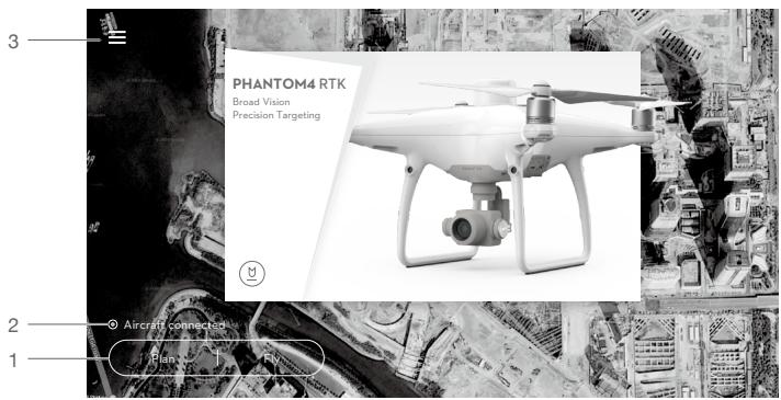
- Plan a Field | Execute Operation
Plan: Tap the button and then select Photogrammetry or Waypoint Flight operation, and then enter Planning View for planning.
Fly: Tap to enter Camera View or Map View to view the aircraft status, configure the settings and perform operations.
- Aircraft Connection Status
○ : Shows whether the aircraft is connected to the remote controller.
- Menu
Tap ≡ to manage tasks, view user information, aircraft information, and configure general settings.
目: Task Management — View the progress of operations, planned operations and imported KML files.
: User Info — View user information of the account logged in.
✗: Aircraft Info — View the information of the connected aircraft.
☀️ : General Settings — Tap for settings such as units of measurement, network diagnosis, and Android system settings
Planning View
Photogrammetry
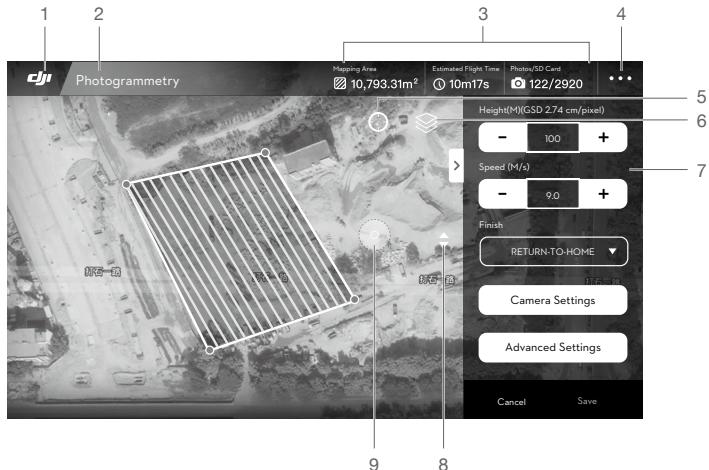
- Main Screen
dj: Tap this icon to return to the main screen.
- Operation Type
Photogrammetry : Shows the current type of operation being planned.
- Planning Information
Shows the mapping area, estimated flight time, and number of photos.
- More Settings
Tap ••• to enter the extended menu to view and adjust the parameters of all other settings. Refer to the introduction for Camera View.
- Location
◎ : Tap to center the map around the aircraft's location or the latest recorded Home Point.
- Map Mode
◇ : Tap to switch among Standard, Satellite, or Night modes.
- Operation Parameters Settings
This settings list will pop-up after edge points added by tapping on the map.
Height: The altitude of the aircraft during the operation.
Speed: The horizontal flight speed during the operation.
Finish: The aircraft action after the operation is completed. Choose from RTH, hovering, landing, and back to the start point.
Camera Settings: Includes photo ratio, white balance, gimbal angle, shutter priority and distortion correction.

If distortion correction is enabled, the image quality may be lower due to processing. It is recommended to disable this option when original images are need for post processing.
Advanced Settings: Includes horizontal overlapping rate, vertical overlapping rate and margin. The vertical overlapping rate indicates the overlapping rate of two pictures captured consecutively along the same path. The horizontal overlapping rate indicates the overlapping rate of two pictures on two parallel paths.
8. Map Zoom In/Out
◆: Tap to show the slider, and then slide it to zoom in or out.
9. Route Direction
☐: The system automatically produces flight routes after adding edge points and setting parameters. Tap and drag this icon to adjust the flight direction of the produced route. Tap the icon for fine tuning in the pop-up menu.
Waypoint Flight
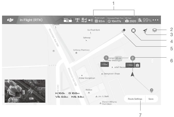
1. Planning Information
Shows the planned route length, estimated flight time, and microSD card capacity.
2. Map Mode
◇ : Tap to switch among Standard, Satellite, or Night modes.
3. Location Follow
: Tap to center the map around the aircraft's location at all times, following its location update.
4. Location
☐: Tap to center the map around the aircraft's location or the latest recorded Home Point.
5. Clear Screen
◆: Tap to clear the flight path currently shown on the map.
6. Waypoints
2: The waypoints added by pressing the C2 Button on the remote controller. Tap to set the flight altitude, heading, speed, gimbal angle and waypoint actions of each waypoint, switch among waypoints, and delete the waypoint.
7. Route Settings | Save
Route Settings: Tap to enter the route settings menu to set task ending action, remote controller signal loss action, aircraft heading in relevance to the flight route, cruising speed and route recording.
Other elements in this view are the same as the ones in Camera View.
Camera View
After tapping Fly in the main screen, users can switch between Camera View and Map View. The descriptions below use the Camera View as an example.
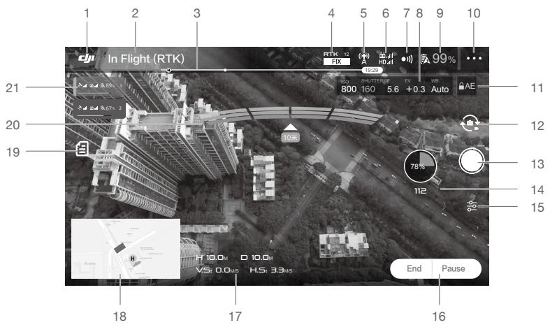
- Main Screen
dj1 : Tap this icon to return to the main screen.
- Aircraft Status
In Flight (RTK)
: Indicates current flight modes and warning messages.
- Battery Level Indicator
- - - - : The battery level indicator provides a dynamic display of the battery level. The colored zones on the battery level indicator represent the power levels needed to carry out different functions.
- RTK / GNSS Signal Strength
RTK 12 FIX : This icon is displayed once the RTK is enabled and begins working properly. The number on the upper right corner indicates the number of satellites connected. The RTK status below includes two statuses: FIX indicates that differential data analysis is completed and RTK can be used for aircraft positioning. Only under this status can the aircraft take off. FLOAT indicates that differential data is in analysis. Waiting for it to be FIX is required.
^12 : This icon is displayed if the RTK is disabled, indicating the current GNSS signal strength and number of satellites connected.
- RTK Data Source Status
Icons displayed when using RTK data. The display varies when using the D-RTK 2 or Network RTK Service.
_,|| : Displays RTK signal strength when using the D-RTK 2.
_ : Indicates that the connection with the D-RTK 2 is abnormal. Refer to the prompts in the app.
^(1) : Displays RTK signal strength when using the Network RTK Service.
^(a)_x : Indicates that the connection with the Network RTK server is abnormal. Refer to the prompts in the app.
- Control and HD Video Link Signal Strength
: Shows the signal strength of the control and HD video downlink connection between the aircraft and the remote controller.
- Obstacle Sensing Function Status
●)) : Tap into this button to enable or disable features provided by the Vision System.
- Camera Parameters
Displays camera settings parameters and capacity of the microSD card.
- Battery Level
99% : Shows the current battery level. Tap to set the Low Battery Warning threshold and view battery information.
- More Settings
Tap ●●● to enter the extended menu to view and adjust the parameters of all other settings.
✿ : Aircraft Settings — Includes Home Point settings, Return to Home Altitude, maximum altitude, distance limit, remote controller signal lost action, advanced settings, etc.
RTK: RTK Settings — Includes RTK function switch, RTK service type and their corresponding settings.
●)) : Sensor Settings — Includes enabling obstacle avoidance, radar map display, advanced vision settings, etc.
: Remote Controller Settings — Includes remote controller calibration, stick mode, linking, etc.
HD : Image Transmission Settings — Includes channel mode and sweep frequency chart selection.
Aircraft Battery Settings — Includes low battery warning thresholds, battery information, etc. When a high discharge current, a short circuit, high or low discharge temperatures or battery cells damage is detected, there will be an on-screen prompt.
☐ : Gimbal Settings — Includes gimbal mode, advanced settings, gimbal roll adjustment, and auto gimbal calibration.
- ●● : General Settings — Includes map settings, flight route display, to find aircraft, etc.
- Auto Exposure Lock
AE : Tap to lock the exposure value.
- Photo/Video Button
: Tap to switch between photo and video recording modes.
- Shutter / Record Button
/ : Tap to shoot photos or start/stop recording. When recording, the time code below the button indicates the length of the recording. Users can also press the Shutter or Video Recording button on the remote controller to shoot photos or record video.
- Operation Progress
70% : Shows the progress of the Photogrammetry operation and number of photos taken.
- Camera Settings
: Tap to set ISO, shutter, exposure values, OSD information, continuous auto focus (available for manual flying and shooting), etc.
- Operation Control Buttons
Buttons to control during different operation types, including invoke, start, pause, or end an operation, etc.
17. Flight Parameters
H: Vertical distance from the aircraft o the Home Point.
☐ : Horizontal distance from the aircraft to the Home Point.
V.S : Movement speed across a vertical distance.
H.S : Movement speed across a horizontal distance.
18. Map
Tap the mini map to switch between Camera View and Map View. The icons ✉️ ➕ ➕ ➕ in Map View are the same as those in Planning View.
19. Operation List
目:Tap to view the planned operations, operations in progress and the imported KML files. Select Plan or Executing in the drop-down menu on top to use the operations. Select KML File to view and edit the data and use the data to plan the Photogrammetry operation area.
20. Obstacle Detection Status
Shows information on the detected obstacles when the obstacle avoidance function is enabled. Front obstacle information appears on the upper screen, and rear obstacle information appears on the lower screen. Red, orange, yellow, and green bars indicate the distance of obstacles in succession. The value indicates the distance between the aircraft and the nearest obstacle.
21. Aircraft Status Box in Multi-Aircraft Control Mode
Displays the status of all the connected aircraft sorted by number when using Multi-Aircraft Control function. Tap to switch the selected aircraft and the left side of the box will turn blue.
natural_image
Line drawing of a quadcopter drone with propellers and control panels (no text or symbols)Flight
This section describes safe flight practices and flight restrictions.
Flight
Once the pre-flight preparation is complete, it is recommended to hone your flight skills through training and practice flying safely. The altitude limit is 1,640 feet (500 meters). Avoid flying at any altitudes higher. It is important to understand basic flight guidelines for the safety of both you and those around you. Refer to the Disclaimer and Safety Guidelines for more information.
Flight Environment Requirements
- Do not use the aircraft in severe weather conditions. These include wind speeds exceeding 10 m/s, snow, rain and fog.
- Only fly in open areas. Tall structures and large metal structures may affect the accuracy of the on-board compass and GNSS system.
- Avoid obstacles, crowds, high voltage power lines, trees, and bodies of water.
- Minimize interference by avoiding areas with high levels of electromagnetism, including base stations and radio transmission towers.
- Aircraft and battery performance is subject to environmental factors such as air density and temperature. Be very careful when flying at altitudes greater than 19, 685 feet (6000 meters) above sea level, as the performance of the battery and aircraft may be affected.
- In the Earth's polar regions the aircraft can only operate in Attitude mode or using vision positioning.
GEO (Geospatial Environment Online) System
Introduction
DJI's Geospatial Environment Online (GEO) System is a global information system committed to providing real-time airspace information within the scope of international laws and regulations. GEO provides flight information, flight times and location information to assist Unmanned Aerial Vehicle (UAV) users in making the best decisions related to their personal UAV use. It also includes a unique Regional Flight Restrictions feature which provides real-time flight safety and restriction updates and blocks UAVs from flying in restricted airspace. While safety and obeying air traffic control laws is a paramount concern, DJI recognizes the need for exceptions to be made under special circumstances. To meet this need, GEO also includes an Unlocking feature that enables users to unlock flights within restricted areas. Prior to making their flight, users must submit an unlock request based on the current level of restrictions in their area.
GEO Zones
DJI's GEO System designates safe flight locations, provides risk levels and safety concerns for individual flights, and offers restricted airspace information, which can be viewed by users in real time on the DJI GS RTK app. The locations designated by GEO are called GEO Zones. GEO Zones are specific flight areas that are categorized by flight regulations and restrictions. GEO Zones that prohibit flight are implemented around locations such as airports, power plants, and prisons. They can also be temporarily implemented around major stadium events, forest fires, or other emergency situations. Certain GEO Zones do not prohibit flight but do trigger warnings informing users of potential risks. All restricted flight areas are referred to as GEO Zones, and are further divided into Warning Zones, Enhanced Warning Zones, Authorization Zones, Altitude Zones, and Restricted Zones. By default, GEO limits flights into or taking off within zones that may result in safety or security concerns. There is a GEO Zone Map, which contains comprehensive global GEO Zone information on the official DJI website: https://www.dji.com/flysafe.
The GEO System is for advisory purposes only. Individual users are responsible for checking official sources and determining which laws or regulations may apply to their flight. In some instances, DJI has selected widely-recommended general parameters (such as a 1.5-mile radius at airports) without making any determination as to whether these guidelines match regulations that apply to specific users.
GEO Zone Definitions
Warning Zones: Users receive a warning message with information relevant to their flight.
Enhanced Warning Zones: Users receive a prompt from the GEO System at the time of flight. They are required to submit an unlock request to fly in the zone, for which they must confirm their flight path.
Authorization Zones: Users receive a warning message and the flight is prohibited by default. Authorization Zones can be unlocked by authorized users with a DJI-verified account. Self-Unlocking privileges must be applied for online.
Altitude Zones: Flights are limited to a specific altitude.
Restricted Zones: Flights are completely prohibited. UAVs cannot fly in these zones. If you have obtained permission to fly in a Restricted Zone, please go to https://www.dji.com/flysafe or contact flysafe@dji.com to unlock the zone.
DJI GEO Zones aim to ensure the user's flight safety, but it cannot be guaranteed to be in full compliance with local laws and regulations. Users should check local laws, regulations, and regulatory requirements before each flight and are responsible for the flight safety.
All intelligent flight features will be affected when DJI aircraft fly nearby or into GEO Zones. Such interference includes, but is not limited to, decreased speed, takeoff failure, and flight termination.
Flight Restrictions
Introduction
UAV operators should abide by all flight regulations established by the relevant government and regulatory agencies, including the ICAO and the FAA. For safety reasons, flights are restricted by default, which helps users operate DJI products safely and legally. Flight restrictions include altitude and distance limits, and GEO Zones.
When Global Navigation Satellite Service (GNSS) is available, altitude limits, distance limits, and GEO Zones are all taken into account to ensure flight safety. Otherwise, only altitude limits take effect.
Maximum Altitude & Radius Restrictions
Maximum flight altitude restricts an aircraft's flight altitude, while maximum radius restricts its distance. These limits can be set using the DJI GS RTK app.
Maximum Flight Altitude
natural_image
3D diagram of a cylinder with internal dashed lines and an arrow indicating vertical distance (no text or labels)Max Radius
Home Point
Height of aircraft when turned on
Strong GNSS Signal
| Restriction | Description | DJI GS RTK App Message |
| Max Altitude | Aircraft's altitude cannot exceed the specified value. | Maximum Flight Altitude reached. Adjust your altitude using Aircraft Settings if required. |
| Max Radius | Flight distance cannot exceed the specified value. | Maximum Flight Distance reached. Adjust your distance using Aircraft Settings if required. |
Weak GNSS Signal
| Restriction | Description | DJI GS RTK App Message |
| Max Altitude | Altitude is restricted to 26 ft (8 m) when GNSS signal is weak and the Vision System is activated. Altitude is restricted to 98 ft (30 m) when GNSS signal is weak and the Vision System is deactivated. | Maximum Flight Altitude reached. Adjust your altitude using Aircraft Settings if required. |
| Max Radius | No limit. | N/A |

- When an aircraft exceeds a specified limit, the pilot can still control the aircraft but it will be unable to fly any farther.
- When an aircraft exceeds the max radius it automatically flies back within range when GNSS signal is strong.
- For safety reasons, do not fly near airports, highways, railway stations, railway lines, city centers, or other sensitive areas. Only fly aircraft in areas that are within your direct line of sight.
GEO Zone Flight Restrictions
| GEO Zone | Description |
| Restricted Zone | Takeoff: The aircraft's motors cannot be started. |
| In-flight: When GNSS signal changes from weak to strong, DJI GS RTK starts a 20-second countdown. Once the countdown is over, the aircraft immediately lands in semi-automatic descent mode and turns off its motors after landing. | |
| In-flight: When the aircraft approaches the boundary of the Restricted Zone, it automatically decelerates and hovers. | |
| Authorization Zone | Takeoff: The aircraft's motors cannot be started. Takeoff is only available after submitting an unlock request with the user's phone number. |
| In-flight: When GNSS signal changes from weak to strong, DJI GS RTK starts a 20-second countdown. Once the countdown is over, the aircraft immediately lands in semi-automatic descent mode and turns off its motors after landing. | |
| Enhanced Warning Zone | The aircraft flies normally but the user is required to confirm the flight path. |
| Warning Zone | The aircraft flies normally but the user receives warning messages. |
| Altitude Zone | When GNSS signal is strong, the aircraft cannot exceed the specified altitude.In-flight: When GNSS signal changes from weak to strong, the aircraft will descend and hover below the altitude limit. |
| When the GNSS signal is strong, the aircraft approaches the boundary of the Altitude Zone. If it is higher than the altitude limit, the aircraft decelerates and hovers in place. | |
| When the GNSS signal changes from weak to strong, DJI GS RTK app starts a 20-second countdown. Once the countdown is over, the aircraft will descend and hover below the altitude limit. | |
| Free Zone | The aircraft flies normally with no restrictions. |
GEO Unlocking
Due to differing laws and regulations between countries and regions, and differing flight restrictions between GEO Zones, DJI provides users with two methods for unlocking GEO Zones: Self-Unlocking and Custom Unlocking.
Self-Unlocking is used for Authorization Zones, where the user is required to submit an unlock request by authenticating their phone number for a registered DJI account. This feature is only available in certain countries. Users can choose whether to submit their unlock request via the website at https://www.dji.com/flysafe (Scheduled Self-Unlocking), or through the DJI GS RTK app (Live Self-Unlocking).
Custom Unlocking is based on special requirements for individual users. It sets a special flight
area that users can unlock by providing flight permission files according to their specific GEO Zone and other requirements. It is available in all countries and can be applied for on the website: https://www.dji.com/flysafe.
For more information about unlocking, please visit https://www.dji.com/flysafe or contact flysafe@dji.com.
Preflight Checklist
- Remote controller, Intelligent Flight Battery are fully charged.
- Propellers are mounted correctly and firmly.
- MicroSD card has been inserted.
- Gimbal and camera are functioning normally.
- Motors can start and are functioning normally.
- The DJI GS RTK app is successfully connected to the aircraft.
- Ensure that the sensors for the Vision System and Infrared Sensing System are clean.
Calibrating the Compass
Only calibrate the compass when the DJI GS RTK app or the status indicator prompt you to do so. Observe the following rules when calibrating your compass:

- DO NOT calibrate your compass where there is a chance of strong magnetic interference, such as magnetite, parking structures, and steel reinforcements underground.
- DO NOT carry ferromagnetic materials with you during calibration such as cellular phones.
- The DJI GS RTK app will prompt you to resolve the compass issue if the compass is affected by strong interference after calibration is complete. Follow the prompted instructions to resolve the compass issue.
Calibration Procedures
Choose an open area to carry out the following procedures.
- Tap the Aircraft Status Bar in the app and select "Calibrate", then follow the on-screen instructions.
- Hold the aircraft horizontally and rotate 360 degrees. The Aircraft Status Indicators will display a solid green light.
- Hold the aircraft vertically, with nose pointing downward, and rotate it 360 degrees around the center axis.
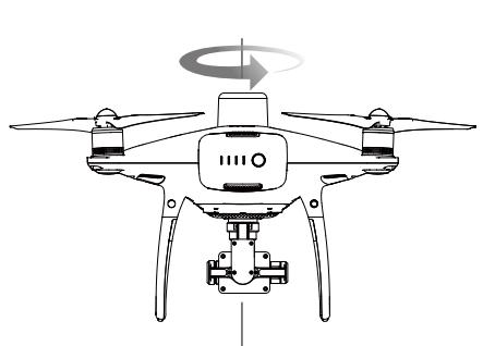
natural_image
Line drawing of a quadcopter drone with a rotating head and propeller base (no text or symbols)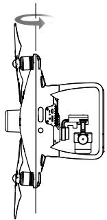
natural_image
Diagram of a helicopter with rotor blades and control panel (no text or symbols)- Re-calibrate the aircraft if the aircraft status indicators glows blinking red.

- If the Aircraft Status Indicator blinks red and yellow after the calibration procedure, move your aircraft to a different location and try again.

- DO NOT calibrate the compass near metal objects such as a metal bridge, cars, scaffolding. - If the aircraft status indicators are blinking red and yellow alternately after placing the aircraft on the ground, the compass has detected magnetic interference. Change your location.
Starting/Stopping the Motors
Starting the Motors
A Combination Stick Command (CSC) is used to start the motors. Push both sticks to the bottom inner or outer corners to start the motors. Once the motors have started spinning, release both sticks simultaneously.
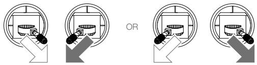
Stopping the Motors
There are two methods to stop the motors.
Method 1: When the aircraft has landed, push the left stick down ①, then conduct the same CSC that was used to start the motors, as described below ②. Motors will stop immediately. Release both sticks once motors stop.
Method 2: When the aircraft has landed, push and hold the left stick down. The motors will stop after three seconds.
①
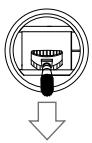
②
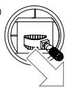
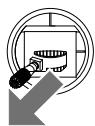
OR
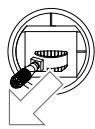
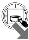
Method 1
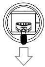
Method 2
Stopping Motors Mid-flight
Perform the CSC to stop the motors. It can be enabled in the app. Go to Camera View > ●●● > ⚙ > Advanced Settings to set the Urgent Stop Mode. Only stop motors mid-flight in emergency situations when doing so can reduce the risk of damage or injury.
Flight Test
Takeoff/Landing Procedures
- Place the aircraft in an open, flat area with the battery level indicators facing towards you.
- Turn on the remote controller and then turn on the Intelligent Flight Battery.
- Launch the DJI GS RTK app and tap Fly.
- Wait until the Aircraft Status Indicators start to blink green slowly, which indicates that GNSS or RTK is in use. If using RTK, ensure that the RTK function is enabled and that the RTK/GNSS signal strength icon shows FIX. Then perform CSC to start motors.
- Push the left stick up slowly to take off.
- To land, hover over a level surface and gently pull down on the left stick to descend.
- After landing, hold the left stick at its lowest position until the motors stop.
- Turn off the Intelligent Flight Battery first, then the remote controller.

- When the Aircraft Status Indicators blink yellow rapidly during flight, the aircraft has entered Failsafe mode.
- A low battery level warning is indicated by the Aircraft Status Indicators blinking red slowly or rapidly during flight.
- Watch our video tutorials for more flight information.
Video Suggestions and Tips
- Go through the full pre-flight checklist before each flight.
- Select the desired gimbal operation mode in the app.
- Only shoot photos or record videos when flying in P-mode.
- Always fly in good weather conditions and avoid flying in rain or heavy wind. An ND filter can be used when the operating environment is too bright.
- Choose the camera settings that suit your needs. Settings include ISO, exposure values, etc.
- Perform flight tests to establish flight routes and preview scenes.
- Push the control sticks gently to keep the aircraft's movement smooth and stable.

It is important to understand basic flight guidelines, for the safety of both you and those around you. Do not forget to read the Disclaimer and Safety Guidelines.
DJI Assistant 2 for Phantom
This section introduces the usage of the DJI Assistant 2 for Phantom software.
DJI Assistant 2 for Phantom
Update firmware, copy flight records and calibrate the Vision System in the DJI Assistant 2 for Phantom software. For users that own DJI Agras aircraft, the DJI Assistant 2 for MG can also be used for the functions above.
Installation and Launching
- Download the software installation file from the Phantom 4 RTK download page: http://www.dji.com/phantom-4-rtk/info#downloads
- Install the software.
- Launch DJI Assistant 2 for Phantom.
Using DJI Assistant 2 for Phantom
Connecting the Aircraft
Connect the Micro USB port of the aircraft to your computer with a Micro USB cable. Then power on the aircraft.

Be sure to remove the propellers before using DJI Assistant 2 for Phantom.
Firmware Update
A DJI account is required for firmware updates. Login with your DJI account or register for one.
Data Upload
Save the flight data recorded by the flight controller or the system logs to a local path or upload them.
Flight Data
Click Open Data Viewer to view flight data. Data Viewer is used to view and analyze the flight data files of the aircraft for performance analysis and troubleshooting.
Calibration
Calibrate the Vision System here when the app prompts for calibration.
Connecting the Remote Controller
Connect the USB-C port of the remote controller to your computer with a USB-C cable. Then power on the remote controller.
Firmware Update
A DJI account is required for firmware updates. Login with your DJI account or register for one.

- DO NOT power off the remote controller during the update.
- DO NOT perform the firmware update while the aircraft is in the air. Only carry out the firmware update when the aircraft is on the ground.
- The remote controller may become unlinked from the aircraft after the firmware update. Relink the remote controller and aircraft if necessary.
Appendix
Appendix
Specifications
| Aircraft | |
| Weight (Battery & Propellers Included) | 1391 g |
| Diagonal Size (Excluding Propellers) | 350 mm |
| Max Ascent Speed | 6 m/s (automatic flight); 5 m/s (manual control) |
| Max Descent Speed | 3 m/s |
| Max Speed | 31 mph (50 kph) (P-mode); 36 mph (58 kph) (A-mode) |
| Max Tilt Angle | 25° (P- mode); 35° (A-mode) |
| Max Angular Speed | 150°/s (A-mode) |
| Max Service Ceiling Above Sea Level | 19685 ft (6000 m) |
| Max Wind Speed Resistance | 10 m/s |
| Max Flight Time | Approx. 30 minutes |
| Operating Temperature | 32° to 104° F (0° to 40° C) |
| Operating Frequency | 2.400 GHz to 2.483 GHz (Europe, Japan, Korea)5.725 GHz to 5.850 GHz (United States, China) |
| EIRP | 2.4 GHzCE (Europe) / MIC (Japan) / KCC (Korea): < 20 dBm5.8 GHzFCC (United States) / SRRC (Mainland China) / NCC (Taiwan, China): < 26 dBm |
| Hover Accuracy Range | RTK enabled and functioning properly:Vertical: ±0.1 m; Horizontal: ±0.1 mRTK disabled:Vertical: ±0.1 m (with vision positioning); ±0.5 m (with GNSS positioning)Horizontal: ±0.3 m (with vision positioning); ±1.5 m (with GNSS positioning) |
| Image Position Offset | The position of the camera center is relative to the phase center of the onboard D-RTK antenna under the aircraft body's axis: (36, 0, and 192 mm) already applied to the image coordinates in Exif data. The positive x, y, and z axes of the aircraft body point to the forward, rightward, and downward of the aircraft, respectively. |
| GNSS | |
| Single-Frequency High-Sensitivity GNSS | GPS + BeiDou + Galileo* (Asia); GPS + GLONASS + Galileo* (other regions) |
* Supported later.
| Multi-Frequency Multi-System High-Precision RTK GNSS | Frequency UsedGPS: L1/L2; GLONASS: L1/L2; BeiDou: B1/B2; Galileo*: E1/E5First-Fixed Time: < 50 sPositioning Accuracy: Vertical 1.5 cm + 1 ppm (RMS); Horizontal 1 cm + 1 ppm (RMS).1 ppm indicates error with a 1 mm increase over 1 km of movement.Velocity Accuracy: 0.03 m/s |
| Mapping Functions | |
| Mapping Accuracy** | Mapping accuracy meets the requirements of the ASPRS Accuracy Standards for Digital Orthophotos Class III. |
| Ground Sample Distance (GSD) | (H/36.5) cm/pixel, H indicates the aircraft altitude relative to the shooting scene (unit: m) |
| Acquisition Efficiency | Max operating area of approx. 1 km2 for a single flight (at an altitude of 182 m, i.e., GSD is approx. 5 cm/pixel, meeting the requirements of the ASPRS Accuracy Standards for Digital Orthophotos Class III). |
| Gimbal | |
| Stabilization | 3-axis (pitch, roll, yaw) |
| Controllable Range | Pitch: -90° to +30° |
| Max Controllable Angular Speed | Pitch: 90°/s |
| Angular Vibration Range | ±0.02° |
| Vision System | |
| Velocity Range | ≤ 31 mph (50 kph) at 6.6 ft (2 m) above ground with adequate lighting |
| Altitude Range | 0 - 33 ft (0 - 10 m) |
| Operating Range | 0 - 33 ft (0 - 10 m) |
| Obstacle Sensory Range | 2 - 98 ft (0.7 - 30 m) |
| FOV | Forward/Rear: 60° (horizontal), ±27° (vertical)Downward: 70° (front and rear), 50° (left and right) |
| Measuring Frequency | Forward/Rear: 10 Hz; Downward: 20 Hz |
| Operating Environment | Surfaces with clear patterns and adequate lighting (> 15 lux) |
| Infrared Sensing System | |
| Obstacle Sensory Range | 0.6 - 23 ft (0.2 - 7 m) |
| FOV | 70°(Horizontal), ±10°(Vertical) |
| Measuring Frequency | 10 Hz |
| Operating Environment | Surface with diffuse reflection material, and reflectivity > 8% (such as wall, trees, humans, etc.) |
| Camera | |
| Sensor | 1" CMOS; Effective pixels: 20M |
* Supported later.
**The actual accuracy depends on surrounding lighting and patterns, aircraft altitude, mapping software used, and other factors when shooting.
| Lens | FOV (Field of View) 84°, 8.8 mm (35 mm format equivalent: 24 mm), f/2.8 - f/11, auto focus at 1 m - ∞ |
| ISO Range | Video: 100 - 3200 (Auto), 100 - 6400 (Manual)Photo: 100 - 3200 (Auto), 100 - 12800 (Manual) |
| Mechanical Shutter | 8 - 1/2000 s |
| Electronic Shutter | 8 - 1/8000 s |
| Max Image Size | 4864×3648 (4:3); 5472×3648 (3:2) |
| Still Photography Modes | Single shot |
| Video Recording Modes | H.264, 4K: 3840×2160 30p |
| Max. Bitrate Of Video | 100 Mbps |
| Photo | JPEG |
| Video | MOV |
| Supported File Systems | FAT32 (≤ 32 GB); exFAT (> 32 GB) |
| Operating Temperature | 32° to 104° F (0° to 40° C) |
| Remote Controller | |
| Operating Frequency | 2.400 GHz to 2.483 GHz (Europe, Japan, Korea)5.725 GHz to 5.850 GHz (United States, China) |
| EIRP | 2.4 GHzCE / MIC / KCC: < 20 dBm5.8 GHzSRRC / NCC / FCC: < 26 dBm |
| Max Transmission Distance | FCC / NCC: 4.3 mi (7 km); CE / MIC / KCC / SRRC: 3.1 mi (5 km)(Unobstructed, free of interference) |
| Power Consumption | 16 W (typical value) |
| Display Device | 5.5 inch screen, 1920×1080, 1000 cd/m2, Android system, 4G RAM + 16G ROM |
| Operating Temperature | 32° to 104° F (0° to 40° C) |
| Intelligent Flight Battery (PH4-5870mAh-15.2V) | |
| Capacity | 5870 mAh |
| Voltage | 15.2 V |
| Battery Type | LiPo 4S |
| Energy | 89.2 Wh |
| Net Weight | 468 g |
| Operating Temperature | 14° to 104° F (-10° to 40° C) |
| Max Charging Power | 160 W |
| Intelligent Flight Battery Charging Hub (P4CH) | |
| Voltage | 17.5 V |
| Operating Temperature | 41° to 104° F (5° to 40° C) |
| Remote Controller Intelligent Battery (WB37-4920mAh-7.6V) | |
| Capacity | 4920 mAh |
| Voltage | 7.6 V |
| Battery Type | LiPo 2S |
| Energy | 37.39 Wh |
| Operating Temperature | -4° to 104° F (-20° to 40° C) |
| Intelligent Battery Charging Hub (WCH2) | |
| Input Voltage | 17.3 to 26.2 V |
| Output Voltage and Current | 8.7 V, 6 A; 5 V, 2 A |
| Operating Temperature | 41° to 104° F (5° to 40° C) |
| AC Power Adapter (PH4C160) | |
| Voltage | 17.4 V |
| Rated Power | 160 W |
Updating the Firmware
Users can update the firmware in the DJI Assistant 2 for Phantom. The DJI GS RTK app can also be used to update the firmware of both the aircraft and remote controller, if using a firmware version of 01.04.0330 or above. Follow the instructions below.
- Power on the remote controller and the aircraft. Ensure that the remote controller has access to the Internet.
- Connect the USB-C port on the remote controller to the Micro USB port on the aircraft via a USB-C OTG cable and a Micro USB cable.
- There will be a prompt on the lower right corner in the DJI GS RTK app if there is new firmware. Tap the text to enter firmware page.
- Select the desired firmware and tap Update to enter firmware information page.
- Tap Download XXX (XXX indicates the firmware version) to download the firmware package for all the devices.
- When the download is complete, tap Update XXX under each device to enter the update page for the corresponding device, then tap Install and wait for the update complete.
- After successfully completing the update, restart the remote controller and the aircraft manually.

- The battery level should be above 30% for the firmware update.
- The remote controller and the aircraft will restart automatically during firmware update. Be sure to keep the connection between the remote controller and the aircraft. DO NOT operate them manually until the app indicates installation is completed.
- The remote controller may become unlinked from the aircraft after the firmware update. Relink the remote controller and aircraft if necessary.
This content is subject to change.
Download the latest version from http://www.dji.com/phantom-4-rtk
If you have any questions about this document, please contact DJI by sending a message to DocSupport@dji.com.
- PHANTOM 4 RTK
- Searching for Keywords
- Navigating to a Topic
- Printing this Document
- Information
- Using this manual
- Legends
- Read Before the First Flight
- Watch the Tutorial Videos
- Download the DJI Assistant 2 for Phantom
- Contents
- Information 2
- Using this manual 2
- Product Profile 6
- Aircraft 13
- Remote Controller 35
- Gimbal and Camera 44
- DJI GS RTK App 48
- Flight 55
- DJI Assistant 2 for Phantom 63
- Appendix 65
- Product Profile
- Introduction
- Features Highlights
- Installation
- Preparing the Aircraft
- Attaching the Propellers
- Battery Installation
- Preparing the Remote Controller
- Mounting the Remote Controller Battery
- Mounting the Dongle and SIM Card
- Unfolding the Remote Controller
- Aircraft Overview
- Remote Controller Overview
- Aircraft
- Profile
- Flight Modes
- Attitude Mode Warning
- Aircraft Status Indicators
- Return to Home (RTH)
- Updating the Home Point
- Failsafe RTH
- Failsafe Illustration
- Smart RTH
- Low Battery RTH
- Precision Landing
- Obstacle Avoidance During RTH
- Landing Protection Function
- Industrial Applications
- KML/KMZ File Import
- Preparing Files
- Importing Files
- Viewing Files
- Photogrammetry
- Planning a Flight Route
- Performing Operations
- Waypoint Flight
- Planning Route
- Edit waypoints
- Operation Safety Notices
- Operation Resumption
- Recording a Breakpoint
- Resuming Operation
- System Data Protection
- Vision System and Infrared Sensing System
- Detection Range
- Calibrating Sensors
- Using Vision Positioning
- Assisted Braking from Obstacle Sensing
- RTK Functions
- Enable/Disable RTK
- Using with the DJI D-RTK 2 Mobile Station
- Using with the Network RTK Service
- Flight Recorder
- Attaching and Detaching the Propellers
- Attaching the Propellers
- Detaching the Propellers
- DJI Intelligent Flight Battery
- DJI Intelligent Flight Battery Functions
- Using the Battery
- Turning ON/OFF
- Low Temperature Notice:
- Checking the Battery Level
- Charging the Intelligent Flight Battery
- Using only the Power Adapter for Charging
- Using the Power Adapter and Charging Hub for Charging
- Connecting to a Power Source
- Connecting Batteries
- Battery Protection LED Display
- Remote Controller
- Using the Remote Controller
- Turning the Remote Controller On and Off
- Charging the Remote Controller
- Controlling the Camera
- Controlling the Aircraft
- Adjusting Controller Sticks
- RTH Button
- Optimal Transmission Range
- Remote Controller Status LED
- Linking the Remote Controlle
- Multi-Aircraft Control Function
- Enter Multi-Aircraft Control Mode
- Switch Control
- Switch in the App
- Switch by the Dial
- Multi-Aircraft Operations
- Exit from Multi-Aircraft Control Mode
- Gimbal and Camera
- Camera
- Camera Micro SD Card Slot
- Micro USB Port
- Camera Operation
- Camera Status LED Indicator Descriptions
- Gimbal
- Gimbal Operation Modes
- DJI GS RTK App
- Main Screen
- Planning View
- Map Zoom In/Out
- Route Direction
- Planning Information
- Map Mode
- Location Follow
- Location
- Clear Screen
- Waypoints
- Route Settings | Save
- Camera View
- Flight Parameters
- Map
- Operation List
- Obstacle Detection Status
- Aircraft Status Box in Multi-Aircraft Control Mode
- Flight
- Flight Environment Requirements
- GEO (Geospatial Environment Online) System
- GEO Zones
- GEO Zone Definitions
- Flight Restrictions
- Maximum Altitude & Radius Restrictions
- GEO Unlocking
- Preflight Checklist
- Calibrating the Compass
- Calibration Procedures
- Starting/Stopping the Motors
- Starting the Motors
- Stopping the Motors
- Stopping Motors Mid-flight
- Flight Test
- Takeoff/Landing Procedures
- Video Suggestions and Tips
- DJI Assistant 2 for Phantom
- Installation and Launching
- Using DJI Assistant 2 for Phantom
- Connecting the Aircraft
- Firmware Update
- Data Upload
- Flight Data
- Calibration
- Connecting the Remote Controller
- Appendix
- Updating the Firmware
Marque : DJI
Modèle : PHANTOM 4 RTK
Catégorie : Drone professionnel