
IC-V8 - Émetteur-récepteur portable ICOM - Notice d'utilisation et mode d'emploi gratuit
Retrouvez gratuitement la notice de l'appareil IC-V8 ICOM au format PDF.
| Type de produit | Émetteur-récepteur portable VHF |
| Marque et modèle | Icom IC-V8 |
| Dimensions (LxHxP) | 54 × 132 × 35 mm (sans accessoires) |
| Poids | 350 g (avec batterie BP-222), 190 g (sans batterie) |
| Alimentation | 7,2 V CC (batterie Icom uniquement, tolérance 6-10,3 V) |
| Puissance de sortie | 5,5 W (HI) / 0,5 W (LO) à 7,2 V |
| Gamme de fréquences | Émission : 144-148 MHz ; Réception : 136-174 MHz (garantie 144-148 MHz) |
| Nombre de canaux mémoire | 107 (dont 1 canal appel, 6 bords de balayage) |
| Stabilité en fréquence | ±10 ppm (de -10°C à +60°C) |
| Connecteur d'antenne | BNC (50 Ω) |
| Consommation | Émission 5,5 W : < 2,0 A ; Réception max. AF : < 250 mA ; Veille : < 70 mA ; Économie d'énergie : < 20 mA |
| Type d'émission | FM (modulation de fréquence à réactance variable) |
| Déviation maximale | ±5,0 kHz |
| Sensibilité (12 dB SINAD) | 0,16 µV typ. |
| Sélectivité | 65 dB typ. |
| Puissance audio | > 0,3 W sous 8 Ω (distorsion 10 %) |
| Température de fonctionnement | -10°C à +60°C |
| Fonctions principales | Balayage programmé, mémoire, prioritaire ; Squelch à tonalité CTCSS/DTCS ; Fonction pager et squelch de code (avec UT-108 en option) ; Verrouillage clavier ; Économie d'énergie ; Minuterie d'émission ; Clonage entre émetteurs-récepteurs |
| Accessoires fournis | Antenne, clip ceinture, feuille OPT 2251, adaptateur secteur, bloc batterie / boîtier piles, socle de charge |
| Entretien | Nettoyer les contacts de la batterie une fois par semaine ; éviter l'exposition à l'eau ; utiliser des accessoires Icom d'origine |
| Sécurité | Ne pas utiliser avec des accessoires non agréés ; maintenir l'antenne à distance du corps lors de l'émission ; respecter les consignes d'exposition RF |
| Réparabilité | Réinitialisation CPU possible (touches SQL + D·CLR + mise sous tension) ; clonage via câble OPC-474 ; option UT-108 installable par l'utilisateur |
FOIRE AUX QUESTIONS - IC-V8 ICOM
Questions des utilisateurs sur IC-V8 ICOM
0 question sur cet appareil. Repondez a celles que vous connaissez ou posez la votre.
Poser une nouvelle question sur cet appareil
Téléchargez la notice de votre Émetteur-récepteur portable au format PDF gratuitement ! Retrouvez votre notice IC-V8 - ICOM et reprennez votre appareil électronique en main. Sur cette page sont publiés tous les documents nécessaires à l'utilisation de votre appareil IC-V8 de la marque ICOM.
MODE D'EMPLOI IC-V8 ICOM
INSTRUCTION MANUAL
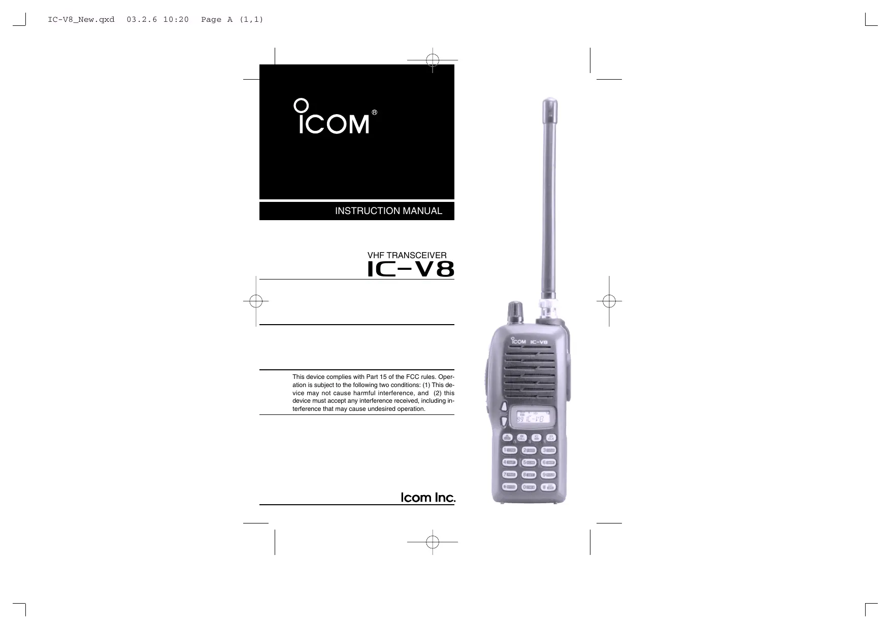
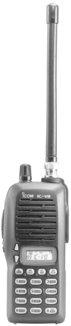
VHF TRANSCEIVER IC-V8
This device complies with Part 15 of the FCC rules. Operation is subject to the following two conditions: (1) This device may not cause harmful interference, and (2) this device must accept any interference received, including interference that may cause undesired operation.
FOREWORD
Thank you for purchasing the IC-V8 FM transceiver. This transceiver is designed for those who require quality, performance and outstanding reliability under the most demanding conditions.
FEATURES
5.5 W of ample output power
O MIL - STD810 grade durability
CTCSS and DTCS encoder/decoder standard
OptionalDTMFdecoder
IMPORTANT
READ ALL INSTRUCTIONS carefully and completely before using the transceiver.
SAVE THIS INSTRUCTION MANUAL—This instruction manual contains important operating instructions for the transceiver.
Icom, Icom Inc. and the ICOM are registered trademarks of Icom Incorporated (Japan) in the United States, the United Kingdom, Germany, France, Spain, Russia and/or other countries.
EXPLICIT DEFINITIONS
The explicit definitions below apply to this instruction manual.
| WORD | DEFINITION |
| △ WARING | Personal injury, fire hazard or electric shock may occur. |
| CAUTION | Equipment damage may occur. |
| NOTE | If disregarded, inconvenience only. No risk of personal injury, fire or electric shock. |
PRECAUTIONS
WARNING! NEVER hold the transceiver so that the antenna is very close to, or touching exposed parts of the body, especially the face or eyes, while transmitting. The transceiver will perform best if the microphone is 5 to 10 ~cm (2 to 4 inches) away from the lips and the transceiver is vertical.
WARNING! NEVER operate the transceiver with a headset or other audio accessories at high volume levels. Hearing experts advise against continuous high volume operation. If you experience a ringing in your ears, reduce the volume or discontinue use.
NEVER connect the transceiver to a power source that is DC fused at more than 5 A. Accidental reverse connection will be protected by this fuse, but higher fuse values will not give any protection against such accidents and the transceiver will be ruined.
PRECAUTIONS—continued
NEVER attempt to charge alkaline or dry cell batteries. Be aware that external DC power connections will charge batteries inside the battery case. This will damage not only the battery case but also the transceiver.
DO NOT push the PTT when not actually desiring to transmit.
Place the unit in a secure place to avoid inadvertent use by children.
DO NOT operate the transceiver near unshielded electrical blasting caps or in an explosive atmosphere.
AVOID using or placing the transceiver in direct sunlight or in areas with temperatures below -10^ (+14^) or above +60^ (+140^) .
The use of non-Icom battery packs/chargers may impair transceiver performance and invalidate the warranty.
Even when the transceiver power is OFF, a slight current still flows in the circuits. Remove the battery pack or case from the transceiver when not using it for a long time. Otherwise, the battery pack or installed Ni-Cd batteries will become exhausted.
For USA only:
Caution: Changes or modifications to this transceiver, not expressly approved by Icom Inc., could void your authority to operate this transceiver under FCC regulations.
SUPPLIED ACCESSORIES
Accessories included with the transceiver:
①


① Antenna 1
② Belt clip 1
③ 2251 OPT sheet 1
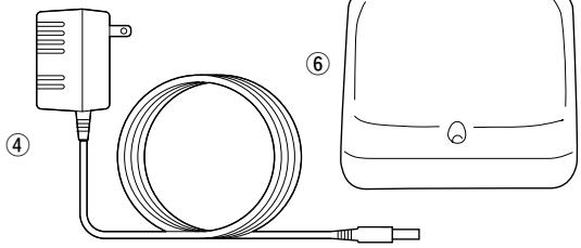
④ AC Adapter 1
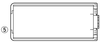
⑤ Battery pack/Battery case 1
⑥ Battery charging stand 1
*Not supplied with some versions.
SAFETY TRAINING INFORMATION
CAUTION
To ensure that your exposure to RF electromagnetic energy is within the FCC allowable limits, always adhere to the following guidelines:
- DO NOT operate the radio without a proper antenna attached, as this may damage the radio and may also cause you to exceed FCC RF exposure limits. A proper antenna is the antenna supplied with this radio by the manufacturer or an antenna specifically authorized by the manufacturer for use with this radio.
- DO NOT transmit for more than 50% of total radio use time ("50% duty cycle"). Transmitting more than 50% of the time can cause FCC RF exposure compliance requirements to be exceeded. The radio is transmitting when the "TX indicator" is lit. You can cause the radio to transmit by pressing the "PTT" switch.
-
ALWAYS use lcom authorized accessories (antennas, batteries, belt clips, speaker/mics, etc.). Use of unauthorized accessories can cause the FCC RF exposure compliance requirements to be exceeded.
-
ALWAYS keep the antenna at least 2.5 ~cm (1 inch) away from the body when transmitting, and only use the lcom belt-clips which are listed in this manual when attaching the radio to your belt, etc. To provide the recipients of your transmission the best sound quality, hold the antenna at least 5 ~cm (2 inches) from your mouth, and slightly off to one side.
The information listed above provides the user with the information needed to make him or her aware of RF exposure, and what to do to assure that this radio operates within the FCC RF exposure limits of this radio. Electromagnetic Interference/Compatibility. During transmissions, your Icom radio generates RF energy that can possibly cause interference with other devices or systems. To avoid such interference, turn off the radio in areas where signs are posted to do so. DO NOT operate the transmitter in areas that are sensitive to electromagnetic radiation such as hospitals, aircraft, and blasting sites.
TABLE OF CONTENTS
FOREWORD
IMPORTANT
EXPLICIT DEFINITIONS
PRECAUTIONS. ii-iii
SUPPLIED ACCESSORIES iv
SAFETY TRAINING INFORMATION .V-Vi
TABLE OF CONTENTS vii-viii
QUICK REFERENCE I-VII
Preparation I-III
■ Your first contact. IV-V
Repeater operation VI
■ Programming memory channels VII
1 ACCESSORIES 1
■ Accessory attachment 1
2 PANEL DESCRIPTION 2-8
Switches, controls, keys and connectors 2-6
■ Function display 7-8
3 BATTERY PACKS 9-15
■ Battery pack replacement 9
■ Battery caution 10
■ Battery charging 11-13
Charging NOTE 14
■ Battery case (optional for some versions) 15
4 BASIC OPERATION 16-20
■Power ON 16
Setting a frequency 16-18
■ Setting audio/squelch level 18
Receive and transmit 19
■Key lock function 19
■ Display type 20
5 REPEATER OPERATION 21-24
■ General 21
Offset frequency 22
■ Subaudible tones 22-23
■ Auto repeater function (USA versions only) 24
6 MEMORY/CALL OPERATION 25-29
■ General 25
Selecting a memory channel 25
Selecting the call channel 25
■ Programming the memory/call channels 26
■ Channel name programming 27
■ Memory transferring 28-29
7DTMF MEMORY 30-31
■ Programming a DTMF code 30
Transmitting a DTMF code 31
DTMF transmission speed 31
8 SCAN OPERATION 32-36
■ Scan types 32
■ Programmed scan 33
■ Memory scan 34
■ Skip channels 34
■Priority watch 35
■ Scan resume condition 36
9 SUBAUDIBLE TONES 37-40
■ Tone squelch 37-38
Pocketbeep operation 39
■ Tone scan 40
10 PAGER/CODE SQUELCH 41-47
■Pager function. 41
■ Code programming 42-44
■Pager operation 45-46
Code squelch 47
11 OTHER FUNCTIONS 48-56
SET MODE 48-50
■ INITIAL SET MODE 51-55
CPU reset 56
12 CLONING 57
13 OPTIONAL UNIT 58-60
■ Optional UT-108 installation 58
■ Optional MB-87 installation 59-60
14 SPECIFICATIONS 61
15 OPTIONS 62-63
QUICK REFERENCE
Preparation
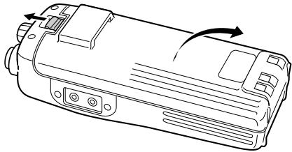
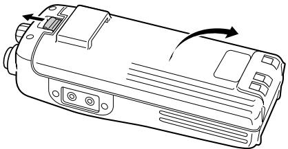
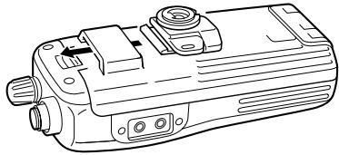
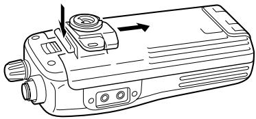
Battery pack replacement
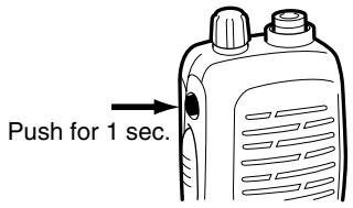
Before replacing the battery pack, push [POWER] for 1 sec. to turn the power OFF.
- Slide the battery release forward, then pull the battery pack upward with the transceiver facing away from you.
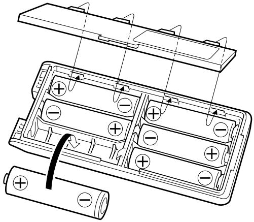
Battery case—optional for some versions
When using a BP-208 BATTERY CASE attached to the transceiver, install 6 AA (R6) size alkaline batteries as illustrated below.
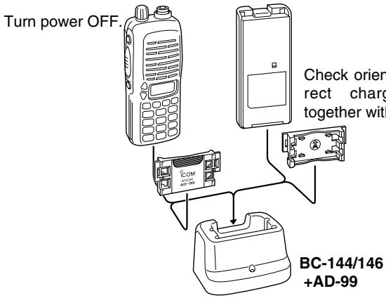
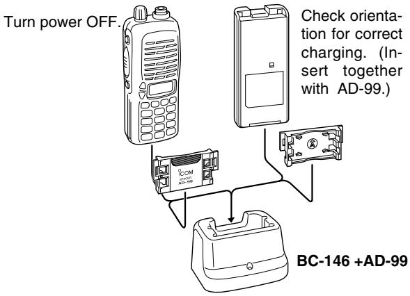
Charging with the BC-144/146
The optional BC-144 provides rapid charging, and the BC-146 provides regular charging of an optional battery pack with/without transceiver. The following is additionally required:
- An optional AC adapter. (An AD-99 is supplied with BC-144/146.)
- About AD-99
Attach the spacer (Spacer B/C) to the adapter (Spacer A) with orientation as illustrated in the diagram below.
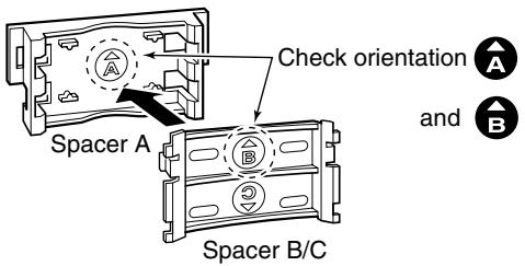
- Attach the spacer (Spacer B/C) to the adapter with the orientation of the stamp “ ” pointing up.
QUICK REFERENCE
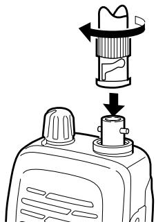
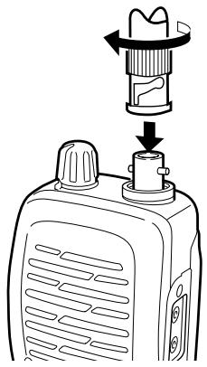
Antenna
Attach the antenna to the transceiver as illustrated at right.
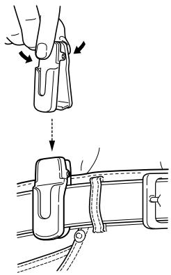
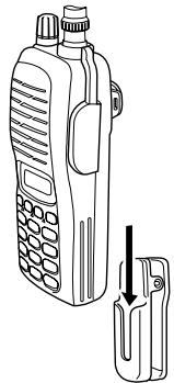
Belt clip
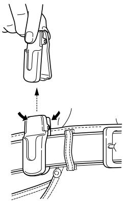
Attach the belt clip to the transceiver as illustrated below.
To attach the belt clip

To release the belt clip

■ Your first contact
Now that you have your IC-V8 ready, you are exited to get on the air. We would like to walk you through a few basic operational steps to make your first "On The Air" use an enjoyable experience.
About default setting
The [VOL] control function can be traded with [] / [] keys function in INITIAL SET MODE. However, in this QUICK REFERENCE, the factory default setting ([VOL] controls audio output level) is used for simple instructions.
Basic operation
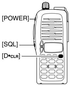
1. Turning ON the transceiver
Although you have purchased a brand new transceiver, some settings may be changed from the factory defaults because of the QC process. Resetting the CPU is necessary to start from factory default.
While pushing [SQL] and [D · CLR], push [POWER] for 1 sec. to reset the CPU and turn power ON.
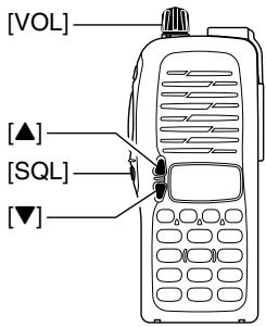
2. Adjusting output level
Rotate [VOL] to set the desired audio level.
3. Adjusting the squelch level
While pushing and holding [SQL], push [] or [] to set the squelch level.
QUICK REFERENCE
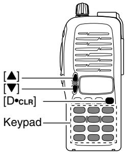
4. Tune the desired frequency
The up/down keys, [] / [] , will allow you to tune to the frequency that you want to operate on. Page 18 will instruct you on how to adjust the tuning step.
Push [] or [] to adjust the frequency.
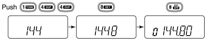
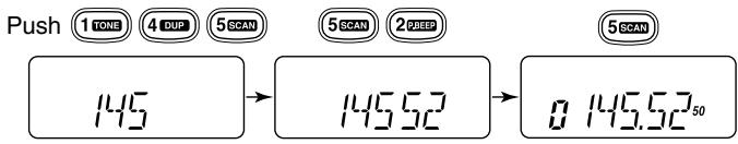
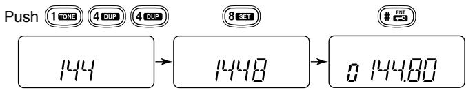
Direct frequency input from the keypad is also available.
To enter the desired frequency, enter 6-digits starting from the 100 MHz digit.
- Enter three to five digits then push [#ENT] to set the frequency.
- When a digit is mistakenly input, push [D.CLR] to abort inputting.
Example 1 when entering 145.525 MHz

Example 2- when entering 144.800MHz
5. Transmit and receive
Push and hold [PTT] to transmit, then speak into microphone; release to receive.
Repeater operation
1. Setting duplex
Push [A*FUNC], then [4*DUP] several times to select minus duplex or plus duplex.
- The USA version has an auto repeater function, therefore, setting duplex is not required.
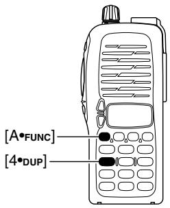
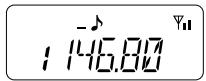
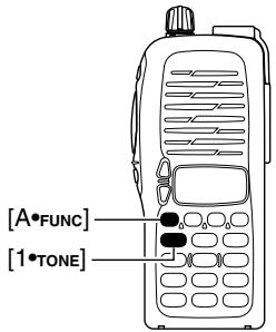
2. Repeater tone
Push [A·FUNC], then [1·TONE] several times until “ ” appears, if required.
QUICK REFERENCE
■ Programming memory channels
The IC-V8 has a total of 107 memory channels (including 6 scan edges and 1 call channel) for storing often used operating frequency, repeater settings, etc.
1. Setting frequency
In VFO mode, set the desired operating frequency with other desired settings, such as repeater and subaudible tone.
2. Selecting a memory channel
Push [A*FUNC], [C*MR] then push [▲]or [▼] several times to select the desired memory channel.
- “MF” indicator and memory channel number blink.

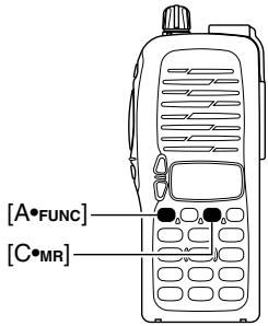
3. Writing a memory channel
Push [A*FUNC], then [C MR] for 1 sec. to program.
3 beeps sound
- Memory channel number automatically increases when continuing to push [C*MR] after programming.
ACCESSIONS
■ Accessory attachment
Antenna
Attach the antenna to the transceiver as illustrated at right.
Keep the jack cover attached when jacks are not in use to avoid bad contacts.
Belt clip
Attach the belt clip to the transceiver as illustrated below.
To attach the belt clip

To release the belt clip

2 PANEL DESCRIPTION
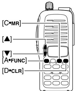
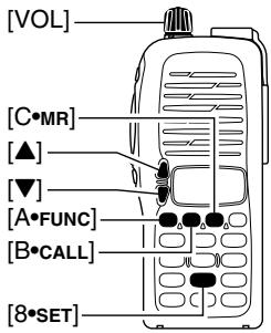
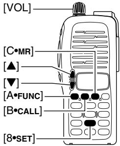
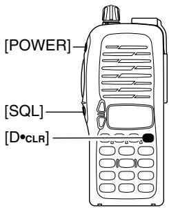
Switches, controls, keys and connectors
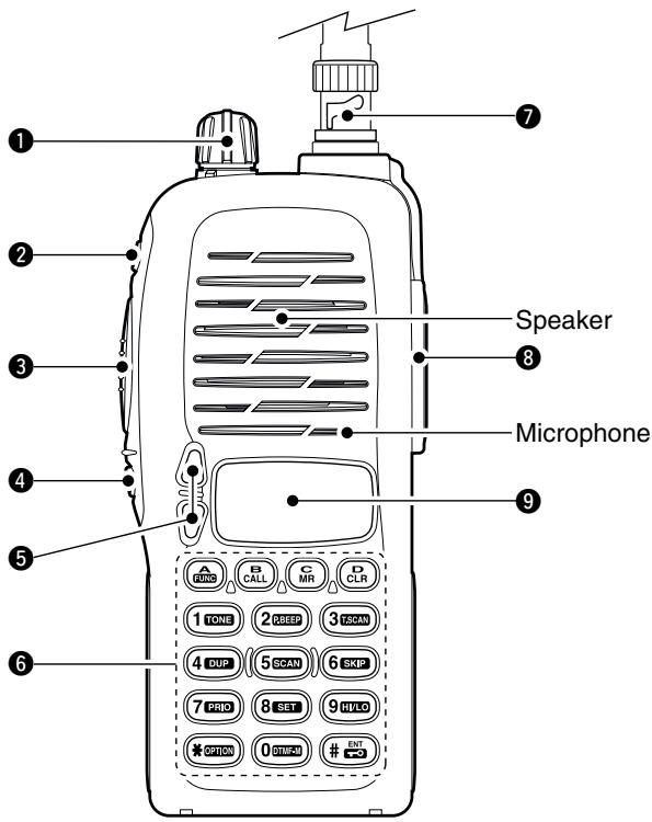
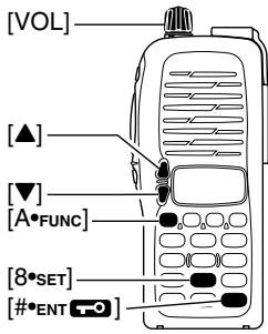
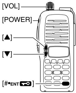
CONTROL DIAL [VOL]
Rotate to adjust the volume level.*
POWER SWITCH [POWER]
Push for 1 sec. to turn the power ON and OFF.
3 PTT SWITCH [PTT]
Push and hold to transmit; release to receive.
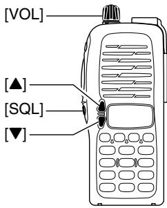
SQUELCH SWITCH [SQL]
Push and hold to force the squelch open and set the transceiver to the squelch level adjustable condition.
UP/DOWN KEYS [ ] / [ ]^*
Selects the operating frequency.*
KEY PAD (pgs. 4-6)
Used to enter operating frequency, the DTMF codes, etc.
7 ANTENNA CONNECTOR
Connects the supplied antenna.
[SP]/[MIC] JACK
Connect an optional speaker-microphone or headset, if desired. The internal microphone and speaker will not function when either is connected.
9 FUNCTION DISPLAY (pgs 7, 8)
*The assigned function for [VOL] and []/[] can be traded in INITIAL SET MODE (pgs. 17, 53).
2 PANEL DESCRIPTION
Key pad

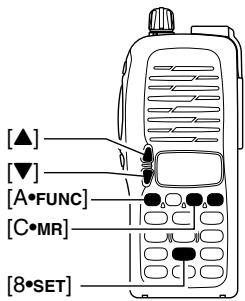
[A•FUNC]
Access to secondary function.

[B · CALL]
Select the call channel. (p. 25)

[C M R]
Selects a memory mode. (p. 25)
After pushing [A·FUNC], entering into memory programming/editing mode. (pgs. 26, 28)
After pushing [A-FUNC], programs/transfers VFO/memory or call channel contents into memory channel/VFO when pushed for 1 sec. (pgs. 26, 28)

[D•CLR]
Selects VFO mode, aborts direct frequency input, or cancels scanning, etc. (pgs. 16, 33)

[1TONE]
Input digit "1" during frequency input, memory channel selection, etc. (pgs. 16, 25)
After pushing [A · FUNC], selects the subaudible tone function. (pgs. 21, 37)

[2*P.BEEP]
Input digit "2" during frequency input, memory channel selection, etc. (pgs. 16, 25)
After pushing [A · FUNC], turn the pocket beep function ON and OFF (p. 39)

[30T.SCAN]
Input digit "3" during frequency input, memory channel selection, etc. (pgs. 16, 25)
After pushing [A·FUNC], starts the tone scanning. (pgs. 23, 40)
Key pad (Continued)

[4 · DUP]
Input digit "4" during frequency input, memory channel selection, etc. (pgs. 16, 25)
After pushing [A-Func], selects a duplex function (-duplex, +duplex, simplex). (p. 21)
![ICOM IC-V8 - [4 · DUP] - 1](/content/2025/01/220705/images/758510ad5aaad7918dab6a6feaaa4a1efce7eb3df837595bd591f74452b71140.jpg)
[5\*SCAN]
Input digit "5" during frequency input, memory channel selection, etc. (pgs. 16, 25)
After pushing [A-Func], starts scanning. (p. 33)
![ICOM IC-V8 - [5\*SCAN] - 1](/content/2025/01/220705/images/8c78374712f3f6e8266e243532c859cf10606634f2925b2bca8f0f6a7dca3501.jpg)
[6\*SKIP]
Input digit "6" during frequency input, memory channel selection, etc. (pgs. 16, 25)
After pushing [A-Func], sets and cancels skip setting for memory skip scan during memory mode. (p. 34)
![ICOM IC-V8 - [6\*SKIP] - 1](/content/2025/01/220705/images/9244f8ba1a3ab3ac75fd4db1c468172697310eea005ae261161d0a2a6ea1724f.jpg)
[7•PRIO]
Input digit "7" during frequency input, memory channel selection, etc. (pgs. 16, 25)
After pushing [A·FUNC], starts the priority watch. (p. 35)
![ICOM IC-V8 - [7•PRIO] - 1](/content/2025/01/220705/images/190c110c4c2c6a7dbb9c1c77fe08147576b50e1a2ae01d0217c42eb746490f53.jpg)
[8\*SET]
Input digit "8" during frequency input, memory channel selection, etc. (pgs. 16, 25)
After pushing [A*FUNC], enters into the SET MODE. (p. 48)
![ICOM IC-V8 - [8\*SET] - 1](/content/2025/01/220705/images/3d5b62820b5524f1badb1f734a56379f5eabb769482c84ed6e138af2441c5c1c.jpg)
[9·HI/LO]
Input digit "9" during frequency input, memory channel selection, etc. (pgs. 16, 25)
After pushing [A·FUNC], switches between high and low output power. (p. 19)
2 PANEL DESCRIPTION
Key pad (Continued)

[O*DTMF-M]
Input digit "0" during frequency input, memory channel selection, etc. (pgs. 16, 25)
After pushing [A·FUNC], enters into the DTMF memory mode. (p. 30)
![ICOM IC-V8 - [O*DTMF-M] - 1](/content/2025/01/220705/images/92da382c759cd484f311d232113b2a58ce25b22cd012bb5419d0b3d9ad2af08e.jpg)
[OPTION]
Selects an optional pager or code squelch operation mode. (p. 43)
![ICOM IC-V8 - [OPTION] - 1](/content/2025/01/220705/images/54b996a7626c5a2e83a63472e311a5550d9efad114e4743e1cbbdb599ce4a62f.jpg)
[#ENT]
Sets the frequency even if the full 6-digits of frequency have not been entered. (p. 16)
After pushing [A·FUNC], switches key pad lock function ON and OFF when pushed for 1 sec. Lock all keys, except [POWER], [PTT], [SQL] and audio level adjustment. (p. 19)
Function display
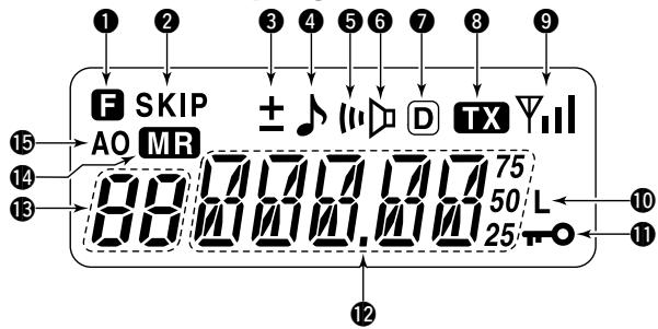
FUNCTION INDICATOR
Appears while a secondary function is being accessed.
SKIP CHANNEL INDICATOR
Appears when the selected memory channel is set as a "skip channel." (p. 34)
3 DUPLEX INDICATOR
Either “-” or “+” appears during repeater operation (p. 21).
4 TONE ENCODER INDICATOR
Appears when tone encoder is in use. (p. 21)
5POCKET BEEP INDICATOR
Appears during pocket beep operation (p. 39).
6 TONE SQUELCH INDICATOR
Appears when tone squelch is in use. (p. 37)
DTCS INDICATOR
Appears when DTCS tone is in use. (p. 37)
⑧ TRANSMIT INDICATOR
Appears during transmit. (p. 19)
2 PANEL DESCRIPTION
Function display (continued)
9 SIGNAL INDICATOR
Appears when the channel is busy and shows receiving signal strength as below.

10 LOW POWER INDICATOR
Appears when low output power is selected. (p. 19)
1 KEY LOCK INDICATOR (p. 19)
Appears when the key lock function is ON.
FREQUENCY READOUT
Shows operating frequency, channel number or channel names, depending on display type (p. 20).
3 MEMORY CHANNEL INDICATOR
Indicates the selected memory channel number or other items such as the call channel, etc. (p. 25)
14 MEMORY MODE INDICATOR
Appears while in memory mode or channel number indication mode. (p. 25)
15 AUTO POWER OFF INDICATOR
Appears while the auto power OFF function is activated. (p. 52)
BATTERY PACKS 3
■ Battery pack replacement
Before replacing the battery pack, push [POWER] for 1 sec. to turn the power OFF.
- Slide the battery release forward, then pull the battery pack upward with the transceiver facing away from you.
BATTERY PACKS
| Battery pack | Voltage | Capacity | Charging period | Battery life*1 | |
| BC-146 | BC-119N, BC-144 or BC-121 | ||||
| BP-208 | Battery case for AA (R6)×6 alkaline | N/A | N/A | —*2 | |
| BP-209 | 7.2 V | 1100 mAh | 12 hrs. | 1.5 hrs. | 7.5 hrs. |
| BP-210 | 7.2 V | 1650 mAh | 18.5 hrs. | 2.0 hrs. | 11 hrs |
| BP-222 | 7.2 V | 600 mAh | 6.5 hrs. | 1.0 hr. | 4 hrs |
^1 Operating periods are calculated under the following conditions; Tx: Rx: standby =5:5:90, power save function: auto setting is activated ^2 Operating period depends on the alkaline cells used.
3 BATTERY PACKS
■ Battery caution
- CAUTION! NEVER short the terminals of the battery pack (or charging terminals of the transceiver). Also, current may flow into nearby metal objects such as a necklace, so be careful when placing battery packs (or the transceiver) in handbags, etc.
Simply carrying with or placing near metal objects such as a necklace, etc. causes shorting. This will damage not only the battery pack, but also the transceiver.
- NEVER incinerate used battery packs. Internal battery gas may cause an explosion.
- NEVER immerse the battery pack in water. If the battery pack becomes wet, be sure to wipe it dry BEFORE attaching it to the transceiver.
- Clean the battery terminals to avoid rust or poor contact.
- Keep battery contacts clean. It's a good idea to clean battery terminals once a week.
If your battery pack seems to have no capacity even after being charged, completely discharge it by leaving the power ON overnight. Then, fully charge the battery pack again. If the battery pack still does not retain a charge (or only very little charge), a new battery pack must be purchased (p. 62).
■ Battery charging
Regular charging with the BC-146
The optional BC-146 provides regular charging of an optional battery pack with/without transceiver. The following is additionally required:
- An optional AC adapter. (An AD-99 is supplied with BC-146.)
3 BATTERY PACKS
About AD-99
Attach the spacer (Spacer B/C) to the adapter (Spacer A) with orientation as illustrated in the diagram below.
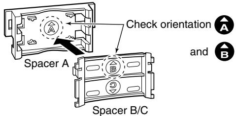
- Attach the spacer (Spacer B/C) to the adapter with the orientation of the stamp “ ” pointing up.
When removing the spacer (Spacer B/C), push the notch carefully with your finger to remove the spacer (Spacer B/C) from the adapter (Spacer A).
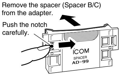
CAUTION!
DO NOT push or force the notch with a screw driver, etc., to remove it.
DO NOT bend the notch when the adapter and spacer are not joined together. This will cause weakening of the notch plastic.
Both cases may break the notch and it may not be able to be reattached.
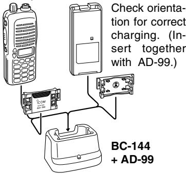
Rapid charging with the BC-144
The optional BC-144 provides rapid charging of optional battery packs.
The following are additionally required:
- An AC adapter (may be supplied with the BC-144 depending on version).
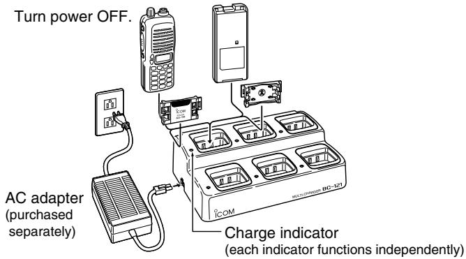
Turn power OFF.
Rapid charging with the BC-121N+AD-94 (#11)
The optional BC-121N allows up to 6 battery packs to be charged simultaneously. The following are additionally required.
- Six AD-94 (#11).
- An AC adapter (BC-124; may be supplied with the BC-121N depending on version).
3 BATTERY PACKS
Charging NOTE
Prior to using the transceiver for the first time, the battery pack must be fully charged for optimum life and operation.
Recommended temperature range for charging: +10^ to +40^ (+50^ to 140^)
- Use the supplied charger or optional charger (BC-119N/121N/144 for rapid charging, BC-146 for regular charging) only. NEVER use other manufacturers' chargers.
The optional BP-222, BP-209 or BP-210 battery packs include rechargeable Ni-Cd (Ni-MH: BP-210) batteries and can be charged approx. 300 times. Charge the battery pack before first operating the transceiver or when the battery pack becomes exhausted.
If you want to charge the battery pack more than 300 times, the following points should be observed:
- Avoid over charging. The charging period should be less than 24 hours.
- Use the battery until it becomes almost completely exhausted under normal conditions. We recommend battery charging after transmitting becomes impossible.
Battery pack life
When the operating period becomes extremely short even after charging the battery pack fully, a new battery pack is needed.
■ Battery case (optional for some versions)
When using a BP-208 BATTERY CASE attached to the transceiver, install 6 AA (R6) size alkaline batteries as illustrated below.

CAUTION
- Use ALKALINE batteries only.
- Make sure all battery cells are the same brand, type and capacity.
- Never mix old and new batteries. Either of the above may cause a fire hazard or damage the transceiver if ignored.
- Never incinerate used battery cells since internal battery gas may cause them to rupture.
- Never expose a detached battery case to water. If the battery case gets wet, be sure to wipe it dry before use.
4 BASIC OPERATION
Power ON
Push [POWER] for 1 sec. to turn power ON.
Setting a frequency
Via the keypad
① Push [D·CLR] to select VFO mode, if necessary.
② To enter the desired frequency, enter 6-digits starting from the 100 MHz digit.
- Enter three to five digits then pushing [#ENT] is also set the frequency.
- When a digit is mistakenly input, push [D.cLR] to abort inputting.
Example 1—when entering 145.525 MHz
Example 2—when entering 144.800MHz
By other methods
Via the [] / [] keys
Push [] or [] several times to set the desired frequency.
- Each push increases/decreases the frequency by the selected tuning step. See page 18 for tuning step details.
For your information—[VOL] function assignment
The [VOL] control can be used as a tuning dial for frequency tuning instead of []/[] keys. However, while [VOL] is functions as tuning dial, []/[] keys functions as AF volume control.
① While pushing [▲] and [▼], turn power ON to enter INITIAL SET MODE.
② Push [▲] or [▼] several times to select the dial assignment item, "tOP."
③ Rotate [VOL] to select the condition.
![ICOM IC-V8 - For your information—[VOL] function assignment - 1](/content/2025/01/220705/images/a2aa3a6dd49d12cdc4000cbb1c2e20067a951278f1599fa97355fdd52e04faa9.jpg)
![ICOM IC-V8 - For your information—[VOL] function assignment - 2](/content/2025/01/220705/images/40d40a79b9b7ab7698423c202084772d65cfc00ebdf3d4a509fcb2bef0b07b72.jpg)
④ To exit set mode, push [#ENT]
4 BASIC OPERATION
Tuning step selection
The IC-V8 has 8 tuning steps—5, 10, 12.5, 15, 20, 25, 30 and 50kHz . The tuning step is selectable in SET MODE.
① Push [A•FUNC] then [8•SET] to enter SET MODE.
② Push [▲]/[▼] several times to select the tuning step item.
③ Rotate [VOL] to select the desired tuning step.
④Push[#ENT]to exit SET MODE.
E5.20
Setting audio/squelch level
To set the audio level
Rotate [VOL] to set the desired audio level while receiving a signal.
- When no signal is received, push and hold [SQL] while setting the audio level.
- When [VOL] is assigned as tuning dial, push []/[] to adjust the audio output level. (pgs. 17, 53)
To set the squelch level
While pushing [SQL], push [] / [] to set the squelch level.
- The squelch level "1" is loose squelch, "10" is tight squelch.
- When [VOL] is assigned as tuning dial, rotate [VOL] while [SQL] is pushed. (pgs. 17, 53)
Receive and transmit
① Push [POWER] for 1 sec. to turn the power ON.
② Adjust audio volume to the desired level.
③ Set a frequency.
When a signal is received:
- Squelch opens and audio is emitted from the speaker.
- Signal indicator shows the relative signal strength level.
④ Push [A•FUNC], then push [9•H/L] to toggle output power between high and low.
-L" appears when low output power is selected.
⑤ Push and hold [PTT] to transmit, then speak into the microphone.
-TX" appears.
- Do not hold the microphone too close to your mouth or speak too loudly. This may distort the signal.
⑥ Release [PTT] to receive.
For your information—Monitor function:
Push and hold [SQL] to listen to weak signals that do not open the squelch.
Key lock function
The key lock function prevents accidental frequency changes and function activation.
Push [A*FUNC] then push [#ENT for 1 sec. to toggle the function ON and OFF.
- "T" appears while the lock function is activated.
- [POWER], [PTT], [VOL] and [SQL] can be operated regardless of this setting.

4 BASIC OPERATION
Display type
USING INITIAL SET MODE
The transceiver has 3 display types to match your operating style. The display type is selected in the INITIAL SET MODE (p. 53).
"Frequency Indication" type
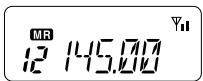
Displays operating frequency.
"Channel Number Indication" type
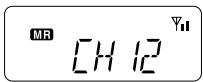
Displays memory channel number. In this type only pre-programmed memory channel numbers are displayed.
VFO mode cannot be selected.
-
When the channel indication type is selected, only the following functions can be performed.
-
Scan function (p. 32)
- Output power setting (p. 19)
-DTMF memory function (p.30) - Key lock function (p. 19)
- Scan pause timer setting, function key timer setting and LCD backlight setting in SET MODE (p. 49)
"Channel Name Indication" type

Displays memory channel name you have assigned. In this display pre-programmed memory channel names are displayed.
VFO mode is selectable.
- Programmed frequencies are indicated pre-programmed in the selected memory channel.
- Push and hold [SQL] to display the operating frequency.
REPEATER OPERATION 5
General
When using a repeater, the transmit frequency is shifted from the receive frequency by the offset frequency. It is convenient to program repeater information into memory channels.
① Set the receive frequency (repeater output frequency).
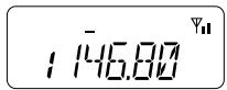
② Push [A•FUNC], then push [4•DUP] several times to select “-” or “+.”
- “-” indicates the transmit frequency is shifted down; “+” indicates the transmit frequency is shifted up.
- Blinking “-” or “+” indicates the reversed duplex mode is selected in SET MODE (p. 48).
③ Push [A•FUNC], then push [1•TONE] to activate the subaudible tone encoder, if required.
"J" appears
- Select the desired subaudible tone frequency, if necessary. (p. 22)
④ Push and hold [PTT] to transmit.
- The displayed frequency automatically changes to the transmit frequency (repeater input frequency).
- If "OFF" appears, check the offset frequency (p. 22) and direction.
⑤ Release [PTT] to receive.
⑥ Push and hold [SQL] to check whether the other station's transmit signal can be directly received or not.
About reversed duplex mode
When the reversed duplex mode is selected, the receive frequency shifts. (Transmit frequency shifts in normal duplex mode.) Each receive and transmit frequency is shown in the table below with the following conditions;
Inputed freq.: 145.30 MHz
Direction: - (negative)
Offset frequency: 0.6 MHz
| Reversed | OFF | ON |
| Rx frequency | 145.30 MHz | 144.70 MHz |
| Tx frequency | 144.70 MHz | 145.30 MHz |
5 REPEATER OPERATION
Offset frequency
USING SET MODE
When communicating through a repeater, the transmit frequency is shifted from the receive frequency by an amount determined by the offset frequency.
① Push [A · FUNC], then push [8 · SET] to enter SET MODE.
② Push [▲] or [▼] several times until “±” and offset frequency appear.
③ Rotate [VOL] to select the desired offset frequency.
- Selectable steps are the same as the pre-set tuning steps.
- The unit of the displayed offset frequency is "MHz."
④ Push [#ENT] to fix the offset frequency and exit SET MODE.
Subaudible tones
USING SET MODE
Some repeaters require subaudible tones to be accessed. Subaudible tones are superimposed over your normal signal and must be set in advance.
① Push [A•FUNC], then push [8•SET] to enter SET MODE.
② Push [▲] or [▼] one or more times until "rt" appears.
③ Rotate [VOL] to select the desired subaudible tone.
④ Push [#ENT] to enter the selected tone and exit set mode.
Available subaudible tone frequencies
(unit: Hz)
| 67.0 | 79.7 | 94.8 | 110.9 | 131.8 | 156.7 | 171.3 | 186.2 | 203.5 | 229.1 |
| 69.3 | 82.5 | 97.4 | 114.8 | 136.5 | 159.8 | 173.8 | 189.9 | 206.5 | 233.6 |
| 71.9 | 85.4 | 100.0 | 118.8 | 141.3 | 162.2 | 177.3 | 192.8 | 210.7 | 241.8 |
| 74.4 | 88.5 | 103.5 | 123.0 | 146.2 | 165.5 | 179.9 | 196.6 | 218.1 | 250.3 |
| 77.0 | 91.5 | 107.2 | 127.3 | 151.4 | 167.9 | 183.5 | 199.5 | 225.7 | 254.1 |
Tone information
Some repeaters require another tone system to be accessed.
DTMF TONES
While pushing [PTT], push the desired DTMF keys (0-9, A-F) to transmit DTMF tones.
The transceiver has 5 DTMF memory channels (p. 30).
1750 Hz TONE
While pushing [PTT], push [] or [] to transmit a 1750Hz tone signal.
Convenient
Tone scan function: When you don't know the subaudible tone used for a repeater, the tone scan is convenient for detecting the tone frequency.
Push [A*FUNC], then push [3*T.scan] to start the tone scan.
- Push [D•CLR] to cancel the scan.
- When the required tone frequency is detected, the scan pauses.
5
Auto repeater
USING INITIAL SET MODE
function (USA version only)
The USA version automatically activates the repeater settings (duplex, ON/OFF, duplex direction, tone encoder ON/OFF) when the operating frequency falls within or outside of the general repeater output frequency range. The offset and repeater tone frequencies are not changed by the auto repeater function. Reset these frequencies, if necessary.
① While pushing [▲] and [▼], turn the power ON to enter INITIAL SET MODE.
② Push [▲] or [▼] several times until "RPt." appears.
③ Rotate [VOL] to select the desired condition.
- "OF"—the auto repeater function is turned OFF;
- "R1"- the auto repeater function activates for duplex only;
- "R2"—the auto repeater function activates for duplex and tone.
④ Push [#ENT] to exit INITIAL SET MODE.
PPE. DF
PPT.P1
PPT.P
Frequency range and offset direction
| FREQUENCY RANGE | DUPLEX DIRECTION |
| 145.200–145.495 MHz | “-” appears |
| 146.610–146.995 MHz | |
| 147.000–147.395 MHz | “+” appears |
MEMORY/CALL OPERATION 6
General
The transceiver has 100 memory channels (plus 3 pairs of scan edges and 1 call channel) for storage of often-used frequencies.
Memory channel contents
The following information can be programmed into the memory:
- Operating frequency
- Duplex direction (+ or -) with an offset frequency (pgs. 21, 22)
- Subaudible tone encoder or tone squelch ON/OFF (pgs. 21, 37)
- Subaudible tone and tone squelch frequencies (pgs. 22, 38)
- Skip information* (p. 34)
*But not scan edge channels.
Selecting a memory channel
① Push [C·MR] to select memory mode.
"MR" appears.
② Enter 2 digits to select the desired memory channel (or push the [] / [] keys).
The memory channels 0-9 are proceeded by a "0."
- When [VOL] is assigned as tuning dial, rotate [VOL] to select the memory channel. (pgs. 17, 53)
Push C MR
145.207
Push
1008 2222
12 45
Selecting the call channel
Push [B·CALL] to select the call channel.
- "C" is displayed instead of the memory channel number.
- Push [D•CLR] or [C•MR] to select VFO or memory mode, respectively.
Push CALL
145.00
“C” appears
6 MEMORY/CALL OPERATION
■ Programming the memory/call channels
① Push [D•CLR] to select VFO mode, if necessary.
② Set the desired frequency.
③ Set other information, such as tone, duplex, as desired.
④ Push [A•FUNC], then [C•MR] momentarily.
- "MR" and memory channel number blink.
⑤ Push [▲] or [▼] to select the desired memory channel.
- When programming the call channel, select "C."
- When [VOL] is assigned as tuning dial, rotate [VOL] to select the memory channel. (pgs. 17, 53)
Push [A•FUNC], then push [C•MR] for 1 sec. (until 3 beeps are emitted) to program the information into the selected memory channel and return VFO
- Continue to hold [C•MR] down for 1 sec. after 3 beeps are emitted, to increment the displayed memory channel number.

■ Channel name programming
① Select a "Channel Name Indication" type in INITIAL SET MODE (p. 53).
② Push [C·MR] to select memory mode, if necessary.
③ Push [A•FUNC], then push [8•SET] to enter into the channel name programming mode.
- The character to be edited blinks.
④ Rotate [VOL] to select a character.
⑤ Push [▲] to move to the right, [▼] to move to the left.
- Up to 5 characters can be used for channel name.
- Usable characters are; A-Z, 0-9, "space", +,-, =, *, /, [and]
⑥ Push [#ENT ] to fix and exit the channel name programming mode.
6 MEMORY/CALL OPERATION
Memory transferring
Memory (call) channel contents can be transferred to the VFO or to another memory channel.
Memory/call VFO
① Select the memory (call) channel to be transferred:
Push [C MR] or [B CALL] to select memory (call) mode.
Push [] or [] to select the memory channel.
- When [VOL] is assigned as tuning dial, rotate [VOL] to select the memory channel. (pgs. 17, 53)
② Push [A•FUNC], then push [C•MR] for 1 sec. to transfer the selected memory contents to the VFO.
- VFO mode is selected automatically.
Memory/call call/memory
① Select the memory (call) channel to be transferred:
Push [C _MR] or [B _CALL] to select the memory (call) mode.
Push [] or [] to select the memory channel.
- When [VOL] is assigned as tuning dial, rotate [VOL] to select the memory channel. (pgs. 17, 53)
② Push [A•FUNC], then push [C•MR] momentarily.
--"and"blink.
③ Push [▲] or [▼] to select the target memory.
- When [VOL] is assigned as tuning dial, rotate [VOL] to select the target channel. (pgs. 17, 53)
④ Push [A•FUNC], then push [C•MR] for 1 sec.
- Memory mode is selected and the contents are transferred to the target memory.
Clearing a memory
① Push [A•FUNC], then push [C•MR] to enter the memory transfer mode.
- “MR” and a memory channel number blink.
② Push [▲] or [▼] to select the memory channel to be cleared.
- When [VOL] is assigned as tuning dial, rotate [VOL] to select the memory channel. (pgs. 17, 53)
- The call channel cannot be cleared.
③ Push [A*FUNC], then push [^] momentarily.
④ Push [A•FUNC], then push [C•MR] for 1 sec.
- Perform step ③ and ④ operations within 1.5 sec, otherwise the memory clearing is cancelled and the transceiver returns to the memory mode.
- The contents of the selected memory are cleared.
⑤ Push [D·CLR] to return to regular operation.
7 DTMF MEMORY
■ Programming a DTMF code
The transceiver has 5 DTMF memory channels (d0 to d4) for storage of often-used DTMF codes of up to 24 digits.
① Push [A*FUNC], then push [O*DTMF-M] to enter the DTMF memory.
- One of "d0" to "d4" appears.
② Rotate [VOL] to select the desired channel.
③ Push [A•FUNC], then push [0•DTMF-M] for 1 sec. to enter the DTMF programming mode.


" _ appears.
- Programmed memories can be cleared in this way.
④ Push the digit keys, [A•FUNC], [B•CALL], [C•MR], [D•CLR], [•OPTION] and [#•ENT ] to enter the desired DTMF code.
- A maximum of 24 digits can be input.
- [•OPTION] enters as “E”, [#•ENT] enters as “F.”
- If a digit is mistakenly input, push [SQL] or [PTT] momentarily then repeat from step ①.
⑤ Push [SQL] or [PTT] to input the digits and exit the DTMF programming mode.
- Programmed DTMF codes sound when [SQL] is pushed to exit.
Transmitting a DTMF code
Using a DTMF memory channel
① Push [A·FUNC], then push [O·DTMF-M] to enter the DTMF memory.
② Rotate [VOL] to select the desired channel.
③ Push [SQL] or [PTT] to exit the DTMF memory mode.
(4) While pushing [PTT], push [SQL] to transmit the selected DTMF memory.
- After the DTMF code is transmitted, the transceiver returns to receive automatically.
Manual DTMF code transmission
While pushing [PTT], push digit keys, A-F to transmit a DTMF code manually.
DTMF
USING INITIAL SET MODE
transmission speed
When slow DTMF transmission speeds are required with DTMF memory transmission (as for some repeaters), the transceiver's rate of DTMF transmission can be adjusted.
① While pushing [▲] and [▼], turn the power on to enter INITIAL SET MODE.
②Push [▲] or [▼] several times until "dtd" appears.
③Rotate [VOL] to select the desired DTMF transmission speed.
- Four speeds are available: "1" (100 msec. intervals) is the fastest; "5" (500 msec. intervals) is the slowest.
④ Push [#ENT] to exit INITIAL SET MODE.
dtd.
dtcd.5
8 SCAN OPERATION
■ Scan types
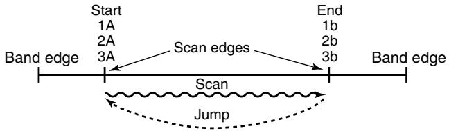
PROGRAMMED SCAN
Programmed scan P1 scans between 1A and 1b, P2 scans between 2A and 2b, and P3 scans between 3A and 3b frequencies.
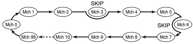
MEMORY (SKIP) SCAN
PRIORITY WATCH

Priority memory channel watch
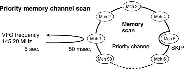
Priority memory channel scan
■ Programmed scan
Programmed scan repeatedly scans between two user programmed frequencies (memory channels "1A-3A" and "1b-3b") or scans between upper and lower band edges. This scan is useful for checking for signals within a specific frequency range such as repeater output frequencies, etc. Scans between lower (start) and high (stop) frequency.
① Push [D·CLR] to select VFO mode, if necessary.
② Push [A•FUNC], then push [5•SCAN] to start the scan, then a selected scan edge appears as “P1,” “P2,” “P3” or “AL.”
- To change the scan edge, push [AFUNC] then push [8SET] several times until the desired scan edge appears.
- "AL" for full scan, "P1", "P2" and "P3" for programmed scan between the programmed scan edge channels as "1A"-1b,"2A"-2b" and "3A"-3b."
To change the scan direction, push [] or [] . - When [VOL] is assigned as tuning dial, rotate [VOL] to change the scan direction. (pgs. 17, 53)
③Push [D*CLR] to stop the scan.
NOTE: Scan edges, 1A-3A/1b-3b, must be programmed in advance. Program them in the same manner as regular memory channels. (p. 26)
If the same frequencies are programmed into the scan edges, programmed scan will not proceed.
8 SCAN OPERATION
Memory scan
Memory scan repeatedly scans all programmed memory channels, except those set as skip channels.
① Push [C·MR] to select memory mode, if necessary.
"MF" appears.
②Push[A·FUNC], then push[5·SCAN] to start the scan.
To change the scan direction, push [ ] or [ ]
- When [VOL] is assigned as tuning dial, rotate [VOL] to change the scan direction. (pgs. 17, 53)
③ Push [D•CLR] to stop the scan.
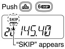
■ Skip channels
In order to speed up the scan interval, you can set memory channels you don't wish to scan as skip channels.
① Push [C*MR] to select memory mode, if necessary.
"MR" appears.
② Select a memory channel to set as a skip channel.
③Push [A•FUNC], then push [6•SKIP] to toggle the skip setting ON and OFF.
- "SKIP" appears when the channel is set as a skip channel.
■ Priority watch
Priority watch checks for signals on "priority channels" while operating on a VFO frequency.
Memory or call channel watch
While operating on a VFO frequency, memory or call channel watch monitors for signals in the selected memory or call channel every 5 sec.
① Select the desired memory channel or the call channel.
② Push [D•CLR] to select VFO mode.
③ Push [A · FUNC], then push [7 · PRI0] to start watching.
- VFO is displayed, then the decimal point ".", on the frequency readout blinks.
- The priority channel is monitored every 5 sec.
- When the signal is detected on the priority channel, the watching is paused according to the setting of the scan resume condition.
④ Push [D•CLR] to stop watching.
Memory scan watch
While operating on a VFO frequency or the call channel, memory scan watch monitors for signals in each memory channel in sequence, every 5 sec.
① Push [C·MR] to select memory mode, if necessary.
"MR" appears.
②Push [A*FUNC], then push [5*SCAN] to start the memory scan.
③ Push [A*FUNC], then push [7*PRIIO] to start the watching.
- VFO is displayed, then the decimal point ".", on the frequency readout blinks.
- When the signal is detected on the priority channel, the watching is paused according to the setting of the scan resume condition.
④ Push [D·CLR] to stop the watching.

SCAN OPERATION
■ Scan resume condition
USING SET MODE
When a signal is received during scanning, the scan resume condition determines what action the transceiver takes. The transceiver has 2 scan resume conditions available as illustrated at right. Use SET MODE to select the one which best suits your needs.
① Push [A · FUNC], then push [8 · SET] to enter SET MODE.
② Push [▲] or [▼] several times until "SCP" or "SCt" appears.
③ Rotate [VOL] to select the desired scan resume condition.
- Pause scan:
When receiving a signal, scan pauses on the signal until it disappears. Resumes 2 sec. after the signal disappears.

Pause scan
- Timer scan:
When receiving a signal, scan pauses on the signal for 5 sec., 10 sec. or 15 sec., then resumes.

Timer scan
④ Push [#ENT ] to set and exit SET MODE.
SUBAUDIBLE TONES 9
■ Tone squelch
Operation
The tone squelch opens only when receiving a signal containing a matching subaudible tone. You can silently wait for calls from group members using the same tone.
① Set the operating frequency.
- Set the AF and squelch to the desired level as the normal operation.
② Set the desired subaudible tone in the SET MODE.
See page 38 for programming.
③ Push [A*FUNC], then push [1*TONE].
- Repeat several times until "D" appears when selecting CTCSS, or "O" appears when selecting DTCS.
④ When the received signal includes a matching tone, squelch opens and the signal can be heard.
- When the received signal's tone does not match, tone squelch does not open, however, the S-indicator shows signal strength.
- To open the squelch manually, push and hold [SQL].
⑤ Operate the transceiver in the normal way.
⑥ To cancel the tone squelch, push [A·FUNC], then push [1·TONE].
- Repeat several times until "凹" or "凹" disappears.
NOTE: The transceiver has 50 tone frequencies and consequently their spacing is narrow compared to units having 38 tones. Therefore, some tone frequencies may receive interference from adjacent tone frequencies.
- To prevent interference from adjacent tone frequencies, using the frequencies as in the following table, is recommended.
Recommended tone frequencies
| 67.0 | 77.0 | 88.5 | 100.0 | 114.8 | 131.8 | 151.4 | 173.8 | 203.5 | 233.6 |
| 69.3 | 79.7 | 91.5 | 103.5 | 118.8 | 136.5 | 156.7 | 179.9 | 210.7 | 241.8 |
| 71.9 | 82.5 | 94.8 | 107.2 | 123.0 | 141.3 | 162.2 | 186.2 | 218.1 | 250.3 |
| 74.4 | 85.4 | 97.4 | 110.9 | 127.3 | 146.2 | 167.9 | 192.8 | 225.7 |
9 SUBAUDIBLE TONES
Setting subaudible tones for tone squelch operation
Separate tone frequencies can be set for tone squelch operation rather than repeater operation (the same range of tones is available—see below). Like the repeater tones, these are set in set mode.
① Select VFO or memory channel.
② Push [A*FUNC], then push [8*SET] to enter SET MODE.
Push [▲] or [▼] several times until "Ct" appears when selecting CTCSS, or "dt" appears when selecting DTCS.
- "D" blinks when selecting CTCSS, or "回" blinks when selecting DTCS.
④ Rotate [VOL] to select the desired subaudible tone.
⑤ Push [#ENT ] to program the selected tone and exit SET MODE.


When SET MODE is selected from memory mode.
Push [A•FUNC], then push [C•MR] for 1 sec. to transfer the contents to VFO.
- 3 beeps are emitted.
VFO mode is selected automatically.
⑦ Push [A•FUNC], then push [C•MR] for 1 sec.
- 3 beeps are emitted.
Steps ⑥ and ⑦ are necessary when overwriting the memory contents permanently. The set tone frequency is used for temporary operation only, therefore, these steps are not necessary.
Available CTCSS tone frequency list
| 67.0 | 79.7 | 94.8 | 110.9 | 131.8 | 156.7 | 171.3 | 186.2 | 203.5 | 229.1 |
| 69.3 | 82.5 | 97.4 | 114.8 | 136.5 | 159.8 | 173.8 | 189.9 | 206.5 | 233.6 |
| 71.9 | 85.4 | 100.0 | 118.8 | 141.3 | 162.2 | 177.3 | 192.8 | 210.7 | 241.8 |
| 74.4 | 88.5 | 103.5 | 123.0 | 146.2 | 165.5 | 179.9 | 196.6 | 218.1 | 250.3 |
| 77.0 | 91.5 | 107.2 | 127.3 | 151.4 | 167.9 | 183.5 | 199.5 | 225.7 | 254.1 |
Pocket beep operation
This function uses subaudible tones for calling and can be used as a "common pager" to inform you that someone has called when you were away from the transceiver.
Waiting for a call from a specific station
① Set the operating frequency.
② Set the desired CTCSS tone frequency or DTCS code in the SET MODE.
See p. 38 for programming details.
③ Push [A*FUNC], then push [1*TONE].
- Repeat several times until “▷” appears when CTCSS, or “▷” appears when DTCS is selected.
④ Push [A•FUNC], then push [2•P.BEEP] to activate the pocket beep function.
"appears.
⑤ When a signal with the matched tone is received, the transceiver emits beep tones and blinks "I."
- Beep tones sound for 30 sec. and "I" blinks. To stop the beeps manually, push any key. "I" continues blinking until step ⑥ is operated.
⑥ Push [PTT] to answer.
- "I," disappears and cancels the pocket beep function automatically.

9 SUBAUDIBLE TONES
■ Tone scan
By monitoring a signal that is being operated with a repeater, pocket beep or tone squelch function, you can determine the tone frequency necessary to access a repeater or open the squelch.
① Set the frequency to be checked for a tone frequency or code.
② Push [A*FUNC], then push [1*TONE].
- Repeat several times to select the tone condition or type to be scanned. (One of “ ,” “ " or “ " appears)
- The tone scan can be operated even if the tone condition or type is not selected.
③ Push [A · FUNC], then push [3 · T.scan] to start the tone scan.
- To change the scanning direction, push [] or [] .
④ When the CTCSS tone frequency or DTCS code is matched, the squelch opens and the tone frequency or code is temporarily programmed into the selected mode such as memory or call channel.
- The tone scan pauses when a CTCSS tone frequency or 3-digit DTCS code is detected.
-
The decoded CTCSS tone frequency or 3-digit DTCS code is used for the tone encoder or tone encoder/decoder depending on the selected tone condition or type in step ②.
-
No indication : Cannot be used for operation.
-“:CTCSS tone encoder
-“D” :CTCSS tone encoder/decoder
-“回” :DTCStone encoder/decoder
⑤ Push [D•CLR] to stop the scan.
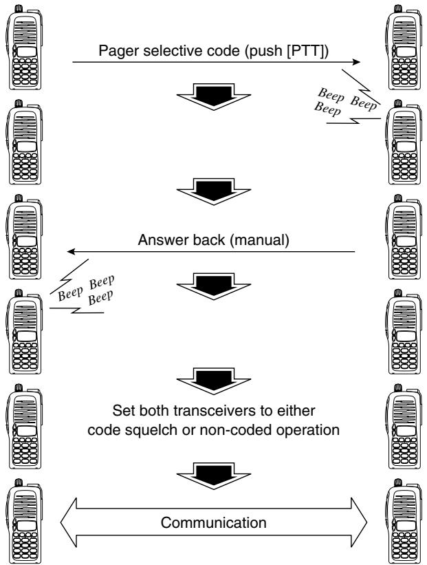
PAGER/CODE SQUELCH 10
■ Pager function
Optional UT-108 required
This function uses DTMF codes for paging and can be used as a "message pager" to confirm you of a caller's identification even when you leave the transceiver temporarily unattended.
10 PAGER/CODE SQUEELCH
Code programming Optional UT-108 required
Before programming
The pager and code squelch functions require ID codes and a group code. These codes are 3-digit DTMF codes and must be written into the code channels before operation.
① Decide the ID code of each transceiver and a group code for your group.
② Decide whether you want to return to normal operation or code squelch operation after a connection is made.
③ Program the ID code, group code and transmit codes (other station's codes) as below.
Code channel assignment
| ID OR GROUP CODE | CODE CHANNEL NUMBER | “RECEIVE ACCEPT” OR “RECEIVE INHIBIT” |
| Your ID code | 0 | “Receive accept” only |
| Other parties’ ID code | 1–6 | “Receive inhibit” should be programmed in each channel. |
| Group code | One of 1–6 | “Receive accept” must be programmed. |
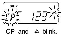
| Memory space* | P | “Receive inhibit” only. |
*Channel CP automatically memorizes an ID code when receiving a pager call. The contents in channel CP cannot be changed manually.
Code programming
An ID code MUST be programmed into code channel C0. Up to 6 transmit codes are programmable into code channels, C1 to C6, if required.
① Push [A*FUNC], then push [ 水 OPTION].
- Pager mode is selected.
100 MHz digit shows "P."
AP5
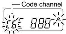
② Push [A · FUNC], then push [8 · SET].
One of either "CP" or "C0" to "C6" blinks.
- "C0" is the ID code and "C1" to "C6" are transmit codes.
续表
③ Rotate [VOL] to select code channel C0.
- A different ID code must be programmed into each transceiver.
④ Enter the desired 3-digit ID code via the keypad.
123
⑤ Rotate [VOL] to select a transmit code channel from C1 to C6.
⑥ Enter the desired 3-digit transmit code via the keypad.
⑦ Push [A•FUNC], then push [6•SKIP] to set the channel for "receive inhibit" or "receive accept."
- When "receive inhibit" is set, "SKIP" appears as at right.
Code channel C0 cannot be set as "receive inhibit." - See the table for "receive accept" and "receive inhibit" details (p. 44).
⑧ Repeat steps ⑤ and ⑥ to set additional transmit code channels, if desired.
Push [#ENT or [PTT] to exit code set mode.
SKIP
10 PAGER/CODE SQUEELCH
- Receive accept/receive inhibit
"Receive accept" ("SKIP" indicator does not appear) accepts pager calls when the transceiver receives a signal with a code the same as that in the code channel.
"Receive inhibit" ("SKIP" indicator appears) rejects calls even when the transceiver receives a code the same as that in the code channel. Transmit codes should therefore be programmed for "receive inhibit," otherwise the transceiver will not reject unnecessary calls.
- Pager/code squelch operation during channel indication
To use these functions in channel indication, the pager/code squelch setting must be programmed with other memory contents before selecting channel number indication.
■ Pager operation
Optional UT-108 required
Calling a specific station
① Program the desired code channel in advance (p. 43).
② Set the operating frequency.
- Set the AF and squelch to the desired level as in normal operation.
③ Push [A*FUNC], then push [ 水 OPTION].
- Pager mode is selected.
-
100 MHz digit shows "P."
-
12
(4) Select the desired transmit code channel:
Push [A*FUNC], then push [8*SET].
Rotate [VOL] to select the desired code channel.
Push [#ENT ] to return to previous condition.
⑤ Push [PTT] to transmit the pager code.
⑥ Wait for an answer back.
- When the transceiver receives an answer back code, the function display shows the other member's ID or group code.
⑦ After confirming a connection, push [A•FUNC], then push [★OPTION] to select the code squelch operation, or repeat the previous key operation again to select non-selective calling system.
- DO NOT push any digit keys while code channels C0 to C6 are displayed, or code channel contents will be changed.
⑧ Communicate with the other party as normal: push [PTT] to transmit; release to receive.
10 PAGER/CODE SQUEELCH
Waiting for a call from a specific station
① Set the operating frequency.
② Push [AFUNC], then push [*OPTION].
100 MHz digit shows "P."
③ Wait for a call.
- When receiving a call, the caller's ID or group code appears as shown below.
- DO NOT push any digit keys while code channels C0 to C6 are displayed, or code channel contents will be changed.
④ Push [PTT] to send an answer back call and display the operating frequency.
⑤ After confirming a connection, push [A•FUNC], then push [★OPTION] to select code squelch operation, or repeat previous key operation again to select non-selective calling system.
PERSONAL CALLS
This display appears when you are called with your ID code and the calling station's ID code is 123.
GROUP CALLS
This display appears when you are called with the group code, 888, and 888 has been programmed into code channel C6.
- ERROR INFORMATION
When the transceiver receives an incomplete signal, "E" and previously received code appear.

Code squelch
Optional UT-108 required
Code squelch provides communications with quiet standby since you will only receive calls from stations which know your ID or group code. Each push of [PTT] sends a 3-digit code in order to open the receiving station's code squelch prior to voice transmission.
① Set the operating frequency.
- Set the AF and squelch to the desired level as in normal operation.
② Push [A*FUNC], then push [ *OPTION].
- Repeat several times, if necessary.
Code squelch mode is selected. - 100 MHz digit shows "C."
③ Select the desired transmit code channel:
Push [A*FUNC], then push [8*SET].
Rotate [VOL] to select the desired code channel.
Push [#ENT to exit code set mode.
④ Operate the transceiver in the normal way (push [PTT] to transmit; release [PTT] to receive).
⑤ To cancel the code squelch, push [A*FUNC], then push [**OPTION].
45.10
- 100 MHz digit shows "1" when the function is cancelled.
11 OTHER FUNCTIONS
SET MODE
Entering SET MODE
① Push [A · FUNC], then push [8 · SET].
② Push [▲] or [▼] to select the desired item.
③ Rotate [VOL] to select the condition/value.
- To exit set mode, push [#•ENT]
Repeater tone frequency
Selects tone encoder frequency for accessing a repeater, etc. from one of 50 available frequencies.
- 67.0-254.1 Hz (50 tones): 88.5 Hz (default)
Tone squelch frequency
Selects frequency for tone squelch or pocket beep operation from one of 50 available frequencies.
- 67.0-254.1 Hz (50 tones): 88.5 Hz (default)
DTCS code
Selects DTCS encoder/decoder code with polarity (N: normal/l: inverse) from one of 208 available codes.
- 023N/I-754N/I: 023N (default)
Offset frequency
Sets the offset frequency for duplex (repeater) operation within 0-20.00 MHz range.
Reverse function
Turns the reverse function ON and OFF.
- Default: OFF


Tuning step
Selects tuning step from 5, 10, 12.5, 15, 20, 25, 30 and 50kHz
5.20
Scan pause timer
Selects the scan pause time from SCt.5, SCt.10, SCt.15 and SCP.2. When receiving signals, the scan pauses according to the scan pause time.
5[1. 15
- SCT. 5/10/15 : Scan pauses for 5/10/15 sec. (default: SCT.15)
5[F. 2]
- SCP.2 : Scan pauses until the signal disappears. Resumes 2 sec. after the signal disappears.
Function key timer
Selects [A-FUNC] effect timer from F0.At, F1.At, F2.At, F3.At and F.m.
FHL
F0.At : "f" disappears immediately after secondary function is operated. (default)
Fm
F1/2/3.At: "n" disappears after 1/2/3 sec. after secondary function is operated.
- F.m : “ u ” appears until [A · FUNC] is pushed again.
LCD backlight
Selects LCD backlight lighting condition from auto, ON and OFF.
L 15.16
-
LIG.At :Lights when any key except [PTT] is pushed. (default)
-
LIG.ON : Lights continuously while the transceiver is powered ON.
-
LIG.OF : Never lights.
11 OTHER FUNCTIONS
Transmission permission
Turns transmission permission ON and OFF. This function can be set for each memory and call channel, independently.
-tX.ON:Transmission is permitted.(default)
- tX.OF: Transmission is inhibited.
14.17
Pager/Code squelch channel
Optional UT-108 required
Programs 3-digit ID code in channel "C0" and individual or group call code in channel "C1" to "C6" for the pager and code squelch functions. See p. 43 for programming details.

*This item appears only when the optional UT-108 is installed and pager or code squelch function is activated.
INITIAL SET MODE
AT POWER ON
The INITIAL SET MODE is accessed at power on and allows you to set seldom-changed settings. In this way, you can "customize" transceiver operations to suit your preference and operating style.
Entering INITIAL SET MODE
① While pushing [▲] and [▼], turn power ON.
② Push [▲] or [▼] to select the desired item.
③ Rotate [VOL] to select the condition or value.
- To exit set mode, push [#*ENT]
Key-touch beep
Turns key-touch beep emission ON and OFF.
- Default: ON
BEPON
Time-out timer
To prevent accidental prolonged transmission, etc., the transceiver has a time-out timer. This function cuts a transmission OFF after 1-30 min. of continuous transmission. This timer can be cancelled.
LDTDF
- tOt.OF : The time-out timer is turned OFF. (default)
- tOt. 1-30: The transmission is cut OFF after the set period elapses.
11 OTHER FUNCTIONS
Auto repeater
The auto repeater function automatically turns ON or OFF the duplex operation and tone encoder. The offset and repeater tone is not changed by the auto repeater function. Reset these frequencies, if necessary.
- RPt.OF : The auto repeater function is turned OFF.
- RPt.R1 : Activates for duplex only. (default)
U.S.A. version only
PPL.DF
PPL
Auto power-off
The transceiver can be set to automatically turn OFF after a specified period with a beep when no key operations are performed.
- 30 min., 1 hour, 2 hours and OFF (default) can be specified. The specified period is retained even when the transceiver is turned OFF by the auto power-off function. To cancel the function, select "POF.OF" in this set
Repeater lock-out
Selects lockout type from repeater, busy and OFF.
- RLO.RP: The repeater lockout is turned ON.
- RLO.bu : The busy lockout is turned ON.
- RLO.OF: No lockout is activated. (default)
PDF.DF
AO
PQF.30
PLD
PLQPP
Squelch delay
Selects squelch delay from short and long to prevent repeated opening and closing of the squelch during reception of the same signal.
- Sqt. S: The squelch closes in short delay. (default)
- Sqt. L: The squelch closes in long delay.
575
DTMF speed
The rate at which DTMF memories send individual DTMF characters can be set to accommodate operating needs.
- 1: 100 msec. interval; 5.0 cps speed (default)
- 2: 200 msec. interval; 2.5 cps speed
- 3: 300 msec. interval; 1.6 cps speed
- 5: 500 msec. interval; 1.0 cps speed (cps=characters/sec.)
cd. 1
Dial assignment
Selects [VOL] control action from AF volume and tuning dial.
-tOP.VO:AF volume (default)
-tOP.dl : Tuning dial
EOPV0
L
Display type
Selects LCD indication type from frequency, channel number and channel names.
- dSP.FR : Shows frequency (default)
dSP.CH: Shows channel number* - dSP.Nm: Shows channel names
*Memory channels only can be selected.
D5PFF
DSPCH
d5Pm
11 OTHER FUNCTIONS
LCD contrast
Selects LCD contrast from auto and low.
- Lcd.AT : Automatic (default)
- Lcd.LO:Low contrast
LcA
Power save
Selects duty cycle for power save function from auto, 1:32, 1:16, 1:8, 1:2 and OFF.
- P-S.At : Duty cycle changes automatically. (default)
P-S.32 : 1:32 duty cycle
P-S.16:1:16 duty cycle - P-S.8 : 1:8 duty cycle
P-S.2:1:2 duty cycle - P-S.OF: The power save function is turned OFF.
P--5.
P--5.3
Tuning speed acceleration
The tuning speed acceleration automatically speeds up the tuning speed when pushing and holding [▲] or [▼], or rotating [VOL] rapidly.*
- S-S.At : The tuning speed acceleration is activated. (default)
- S-S. m : The tuning speed acceleration is not activated.
*When tuning dial is assigned with [VOL].
5-5.1L
m
Mic simple mode
Optional HM-75A required
This item turns the microphone simple mode ON and OFF. Microphone simple mode is used to change the function assignments for keys in the optional HM-75A REMOTE CONTROL SPEAKER-MICROPHONE as below. This assignment is convenient for 3-channel use of simple operation.


- mIC.N1 : Normal 1 (default)
- mIC.N2 : Normal 2
- mIC.Sm : Simple mode
| HM-75A key | Mode | NORMAL1 | NORMAL2 | SIMPLE |
| [A] | Freq. CH | [B•CALL] Null | [SQL] | [SQL] |
| [B] | Freq. CH | VFO/Memory Null | VFO/Memory Null | [B•CALL] |
| [▲] | Freq. CH | Freq. Up Memory CH Up | Freq. Up Memory CH Up | MR-00CH |
| [▼] | Freq. CH | Freq. Down Memory CH Down | Freq. Down Memory CH Down | MR-01CH |
A 1750Hz tone can be transmitted with the HM-75A operation.
Push [A] while pushing [PTT].
NOTE:
Turn power OFF when connecting the HM-75A to the transceiver.
VFO mode cannot be selected via the microphone when SIMPLE mode is selected.
11 OTHER FUNCTIONS
CPU reset
AT POWER ON
The function display may occasionally display erroneous information (e.g. when first applying power). This may be caused externally by static electricity or other factors.
If this problem occurs, turn power OFF. After waiting a few seconds, turn power ON again. If the problem persists, perform CPU resetting operation as follows.
- While pushing [SQL] and [D*CLR], turn power ON.
CAUTION:
Resetting the CPU returns the radio to factory default settings.
CLONING 12
Cloning allows you to quickly and easily transfer the programmed contents from one transceiver to another transceiver.
Transceiver-to-transceiver cloning
AT POWER ON
① Connect the OPC-474 CLONING CABLE to the [SP] jack of the master and sub-transceivers.
- The master transceiver is used to send data to the sub-transceiver.
② While pushing [A•FUNC] and [▲], turn power ON to enter cloning mode (master transceiver only—power ON only for sub-transceiver).
- "CLONE" appears and the transceivers enter the clone standby condition.
③ Push [PTT] on the master transceiver.
- "CL" appears in the master transceiver's display and two digit numbers show that data is being transferred to the sub-transceiver.
- "CL IN" appears automatically in the sub-transceiver's display and two digit numbers show that data is being received from the master transceiver.
(4) When cloning is finished, turn power OFF, then ON again to exit cloning mode.
Cloning using a PC
Please refer to the HELP file that comes with CS-V8 CLONING SOFTWARE.
NOTE: DO NOT push the [PTT] on the sub-transceiver during cloning. This will cause a cloning error.
13 OPTIONAL UNIT
■ Optional UT-108 installation
① Remove the optional connector access cover (named 2251 OPT sheet).
- Insert a screwdriver into the hollow of the chassis, then lift and take away the cover. (The cover cannot be used again.)
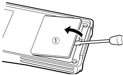
WARNING!
NEVER attempt to remove the optional connector cover using
your finger nails, this may result in injury.
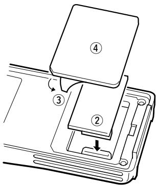
② Attach the optional unit. Insert the connector tightly to avoid a bad contact.
③ Remove the paper backing of 2251 OPT sheet supplied as an accessory.
④ Attach the new 2251 OPT sheet to the service window.
⑤ Program the necessary information from the transceivers key pads or using the cloning software, before operation.
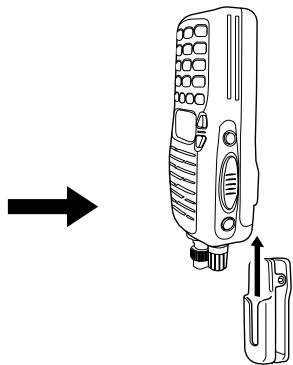
■ Optional MB-87 installation
MB-87 stopper
To attach the stopper
To release the stopper
MB-87 belt clip
When clipping to a part of your belt
When releasing
13 OPTIONAL UNIT
MB-87 stopper
- When attaching
- When removing

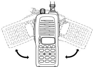
Once the transceiver is locked in place, it will swivel 360 degrees.
CAUTION!
HOLD THE TRANSCEIVER TIGHTLY, WHEN ATTACHING OR REMOVIDING THE TRANSCEIVER FROM THE BELT CLIP.
If the transceiver is accidentally dropped and the swivel belt clip's stopper is cracked or damaged, the swivel belt clip may not work properly.
SPECIFICATIONS 14
General
Frequency range USA General (LM)
- Operating temp. range
Frequency stability
- Antenna connector
- Power supply requirement
- Current drain (at 7.2 V DC)
Transmit at 5.5 W
at 0.5 W
Receive at max. AF
Stand-by
Power save
No. of memory channels
Tuning steps
- Dimensions (projections not included)
Weight (approx.)
144-148 MHz (Tx), 136-174 MHz* (Rx)
136-174 MHz* (Tx/Rx)
*Guaranteed 144-148 MHz range only
: -10°C to +60°C; +14°F to +140°F
: ±10 ppm (-10°C to +60°C)
: BNC (50 Ω)
: 7.2 V DC (6-10.3 V DC acceptable; Icom's battery pack only)
:
Less than 2.0 A
Less than 0.8 A
Less than 250mA
Less than 70 mA
Less than 20mA
: 107 (incl. 1 call and 6 programmed scan edges)
: 5, 10, 12.5, 15, 20, 25, 30 and 50kHz
: 54(W)×132(H)×35(D) mm
; 2^1 / 8(W)× 5^3 / 16(W)× 1^3 / 8(W) in.
: 350 g; 12.3 oz (with BP-222)
190 g; 6.7 oz (without battery pack)
Transmitter
- Modulation system
Output power (at 7.2 V DC)
Max. frequency deviation
Spurious emissions - External mic. connector
: Variable reactance frequency modulation
: 5.5 W (High), 0.5 W (Low)
:±5.0 kHz
Less than -60 dB
: 3-conductor 2.5 (d) mm; 2.2k
Receiver
Receiving system
Intermediate frequencies
- Sensitivity (at 12 dB SINAD)
- Squelch sensitivity
- Selectivity
- Intermodulation rejection
- Spurious & image rejection
Audio output power (at 7.2 V DC)
- External speaker connector
: Double conversion superheterodyne system
: 1st: 21.7 MHz, 2nd: 450 kHz
: 0.16 V typ.
: 0.1 V typ.
: 65 dB typ.
: 65 dB typ.
:75dBtyp.
More than 0.3 W at 10% distortion with an 8Ω load
: 2-conductor 3.5 (d) mm; 8 Ω
15 OPTIONS
BATTERY PACKS
| Battery Pack | Voltage | Capacity | Output Power | Operating Period*1 |
| BP-208*2 | Battery case for R6 (AA) ×6 alkaline cells | 5.5 W | — | |
| BP-209 | 7.2 V | 1100 mAh | 5.5 W | 7.5 hrs. |
| BP-210 | 7.2 V | 1650 mAh | 5.5 W | 11 hrs. |
| BP-222 | 7.2 V | 600 mAh | 5.5 W | 4 hrs. |
1Operating periods are calculated under the following conditions:
Tx:Rx:standby=5:5:90, power save function: auto setting, is activated
^2 Operation with the LOW output power selection is recommended.
CHARGER
- BC-144 DESKTOP CHARGER + BC-145 AC ADAPTER
For rapid charging of battery packs. An AC adapter is supplied with the charger. Charging time: 1.5 to 2 hrs. - BC-137 (#11) BATTERY CHARGER + BC-122 AC ADAPTER
For regular charging of battery packs. An AC adapter is additionally required. Charging time: 15 hrs.
- BC-146 BATTERY CHARGER + BC-147 AC ADAPTER
For regular charging of battery packs. An AC adapter is additionally required. Charging time: 18.5 hrs.
- BC-121N MULTI-CHARGER + AD-94 (#11) CHARGER ADAPTER (6 pcs.) For rapid charging of up to 6 battery packs (six AD-94's are required) simultaneously. An AC adapter may be supplied depending on version. Charging time: 1.5 to 2 hrs.
- BC-119N DESKTOP CHARGER + AD-94 (#11) CHARGER ADAPTER For rapid charging of battery packs. An AC adapter is supplied with the charger. Charging time: 1.5 to 2 hrs.
INTERNAL UNIT
- UT-108 DTMF DECODER UNIT
Provides pager and code squelch capabilities.
OTHER OPTIONS
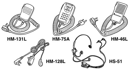
- HM-54/HM-46L/HM-75A/HM-131L SPEAKER-MICROPHONES
Combination speaker-microphones that provide convenient operation while hanging the transceiver from your belt.
HM-75A has 4 function switches for remote control capabilities.
HM-131L has moisture proof construction.
HM-128LEARPHONE-MICROPHONE
You can clip the microphone with PTT switch to your lapel or breast pocket.
HS-51 HEADSET
Allows you hands-free operation. Includes VOX, PTT and "onetouch" PTT with time-out timer.
- MB-68/MB-74/MB-87 BELT CLIPS
MB-68: Same as that supplied with the transceiver.
MB-74: Exclusive alligator-type belt clip.
MB-87: Swivel belt clip
- OPC-474 CLONING CABLE
For cloning between transceivers.
SP-13 EARPHONE
Provides clear receive audio in noisy environments.
- INSTRUCTION MANUAL
- VHF TRANSCEIVER IC-V8
- FOREWORD
- FEATURES
- IMPORTANT
- EXPLICIT DEFINITIONS
- PRECAUTIONS
- PRECAUTIONS—continued
- For USA only:
- SUPPLIED ACCESSORIES
- SAFETY TRAINING INFORMATION
- CAUTION
- TABLE OF CONTENTS
- MEMORY/CALL OPERATION 25-29
- 7DTMF MEMORY 30-31
- SCAN OPERATION 32-36
- SUBAUDIBLE TONES 37-40
- PAGER/CODE SQUELCH 41-47
- OTHER FUNCTIONS 48-56
- CLONING 57
- OPTIONAL UNIT 58-60
- SPECIFICATIONS 61
- OPTIONS 62-63
- QUICK REFERENCE
- Preparation
- Battery pack replacement
- Battery case—optional for some versions
- Charging with the BC-144/146
- - About AD-99
- Antenna
- Belt clip
- ■ Your first contact
- About default setting
- Basic operation
- Turning ON the transceiver
- Adjusting output level
- Adjusting the squelch level
- Tune the desired frequency
- Example 1 when entering 145.525 MHz
- Example 2- when entering 144.800MHz
- Transmit and receive
- Repeater operation
- Setting duplex
- Repeater tone
- ■ Programming memory channels
- Setting frequency
- Selecting a memory channel
- Writing a memory channel
- ACCESSIONS
- ■ Accessory attachment
- PANEL DESCRIPTION
- Switches, controls, keys and connectors
- Key pad
- Key pad (Continued)
- [4 · DUP]
- [5\*SCAN]
- [6\*SKIP]
- [7•PRIO]
- [8\*SET]
- [9·HI/LO]
- [O*DTMF-M]
- [OPTION]
- [#ENT]
- Function display
- Function display (continued)
- SIGNAL INDICATOR
- LOW POWER INDICATOR
- KEY LOCK INDICATOR (p. 19)
- FREQUENCY READOUT
- MEMORY CHANNEL INDICATOR
- MEMORY MODE INDICATOR
- AUTO POWER OFF INDICATOR
- BATTERY PACKS 3
- ■ Battery pack replacement
- BATTERY PACKS
- BATTERY PACKS
- ■ Battery caution
- ■ Battery charging
- Regular charging with the BC-146
- About AD-99
- CAUTION!
- Rapid charging with the BC-144
- Rapid charging with the BC-121N+AD-94 (#11)
- Charging NOTE
- Battery pack life
- ■ Battery case (optional for some versions)
- BASIC OPERATION
- Power ON
- Setting a frequency
- Via the keypad
- Example 1—when entering 145.525 MHz
- Example 2—when entering 144.800MHz
- By other methods
- Via the [] / [] keys
- For your information—[VOL] function assignment
- Tuning step selection
- Setting audio/squelch level
- To set the audio level
- To set the squelch level
- Receive and transmit
- For your information—Monitor function:
- Key lock function
- Display type
- "Frequency Indication" type
- "Channel Number Indication" type
- "Channel Name Indication" type
- REPEATER OPERATION 5
- General
- About reversed duplex mode
- REPEATER OPERATION
- Offset frequency
- Subaudible tones
- Available subaudible tone frequencies
- Tone information
- DTMF TONES
- Hz TONE
- Convenient
- Auto repeater
- function (USA version only)
- MEMORY/CALL OPERATION 6
- Memory channel contents
- Selecting a memory channel
- Selecting the call channel
- MEMORY/CALL OPERATION
- ■ Programming the memory/call channels
- ■ Channel name programming
- Memory transferring
- Memory/call VFO
- Memory/call call/memory
- Clearing a memory
- DTMF MEMORY
- ■ Programming a DTMF code
- Transmitting a DTMF code
- Using a DTMF memory channel
- Manual DTMF code transmission
- DTMF
- transmission speed
- SCAN OPERATION
- ■ Scan types
- PRIORITY WATCH
- ■ Programmed scan
- Memory scan
- ■ Skip channels
- ■ Priority watch
- Memory or call channel watch
- Memory scan watch
- SCAN OPERATION
- ■ Scan resume condition
- - Pause scan:
- - Timer scan:
- SUBAUDIBLE TONES 9
- ■ Tone squelch
- Operation
- Recommended tone frequencies
- SUBAUDIBLE TONES
- Setting subaudible tones for tone squelch operation
- Available CTCSS tone frequency list
- Pocket beep operation
- Waiting for a call from a specific station
- ■ Tone scan
- PAGER/CODE SQUELCH 10
- ■ Pager function
- PAGER/CODE SQUEELCH
- Code programming Optional UT-108 required
- Before programming
- Code programming
- - Receive accept/receive inhibit
- - Pager/code squelch operation during channel indication
- ■ Pager operation
- Calling a specific station
- PERSONAL CALLS
- GROUP CALLS
- - ERROR INFORMATION
- Code squelch
- Optional UT-108 required
- OTHER FUNCTIONS
- SET MODE
- Entering SET MODE
- Repeater tone frequency
- Tone squelch frequency
- DTCS code
- Reverse function
- Tuning step
- Scan pause timer
- Function key timer
- LCD backlight
- Transmission permission
- Pager/Code squelch channel
- INITIAL SET MODE
- AT POWER ON
- Entering INITIAL SET MODE
- Key-touch beep
- Time-out timer
- U.S.A. version only
- Auto power-off
- Repeater lock-out
- Squelch delay
- DTMF speed
- Dial assignment
- LCD contrast
- Power save
- Tuning speed acceleration
- Mic simple mode
- Optional HM-75A required
- NOTE:
- CPU reset
- CAUTION:
- CLONING 12
- Transceiver-to-transceiver cloning
- Cloning using a PC
- OPTIONAL UNIT
- ■ Optional UT-108 installation
- WARNING!
- ■ Optional MB-87 installation
- MB-87 stopper
- MB-87 belt clip
- - When attaching
- - When removing
- HOLD THE TRANSCEIVER TIGHTLY, WHEN ATTACHING OR REMOVIDING THE TRANSCEIVER FROM THE BELT CLIP.
- SPECIFICATIONS 14
- General
- Transmitter
- Receiver
- OPTIONS
- CHARGER
- INTERNAL UNIT
- OTHER OPTIONS
Marque : ICOM
Modèle : IC-V8
Catégorie : Émetteur-récepteur portable