3310 - Tronçonneuse HUSQVARNA - Notice d'utilisation et mode d'emploi gratuit
Retrouvez gratuitement la notice de l'appareil 3310 HUSQVARNA au format PDF.

| Type de machine | Électromécanique |
| Nombre de points | Plus de 10 |
| Type de points | Droit, zigzag, décoratifs |
| Vitesse de couture | Variable, jusqu'à 800 points/min |
| Enfile-aiguille automatique | Oui |
| Réglage de la tension du fil | Manuel |
| Type de canette | Canette horizontale |
| Éclairage intégré | Oui, lampe LED |
| Table d'extension | Amovible |
| Alimentation | Électrique |
| Poids | Environ 7 kg |
| Accessoires inclus | Différents pieds presseurs, tournevis, canettes |
| Dimensions (LxHxP) | Environ 40 x 30 x 20 cm |
| Garantie | Non précisé |
| Utilisation recommandée | Usage domestique et semi-professionnel |
FOIRE AUX QUESTIONS - 3310 HUSQVARNA
Questions des utilisateurs sur 3310 HUSQVARNA
0 question sur cet appareil. Repondez a celles que vous connaissez ou posez la votre.
Poser une nouvelle question sur cet appareil
Téléchargez la notice de votre Tronçonneuse au format PDF gratuitement ! Retrouvez votre notice 3310 - HUSQVARNA et reprennez votre appareil électronique en main. Sur cette page sont publiés tous les documents nécessaires à l'utilisation de votre appareil 3310 de la marque HUSQVARNA.
MODE D'EMPLOI 3310 HUSQVARNA
TECHNICAL BRIEFING
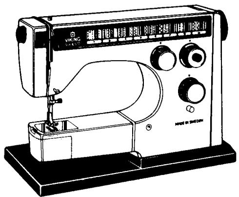
VIKING

INTRODUCTION
This Technical Service Manual has been written to meet the ever increasing requests for knowledge by Viking technicians. This manual endeavors to thoroughly cover the sections listed below:
- Setting Tools and Gauges
- A Technical Briefing of The Viking Sewing Machine
- Removing the Machine Covers
- Inspecting Parts for Damage
- Checking the Noise Level and Machine Speed
- Electrical Checks and Adjustments for the 6570
- Service Checks and Adjustments
- Component Removal and Installation
- Component Repair
- Electrical Wiring of Terminal Blocks and Foot Controls
The sections 3,4,5,6 and 7 are meant to be followed in sequence when doing a full service on a Viking sewing machine.
In section 7, SERVICE CHECKS AND ADJUSTMENTS, the first page of each adjustment explains the requirement and adjustment procedure for the latest series of machines. If the adjustment differs from model to model you will find the correct instructions for that particular machine on a following page.

STITCH FORMATION
The primary function when sewing is to join two pieces of fabric with thread. When sewing by hand one thread is used. However, this requires that the entire needle must go through the fabric. When sewing by machine, two threads are used instead, which are intertwined,
thereby avoiding the necessity of drawing the whole length of thread through the fabric.
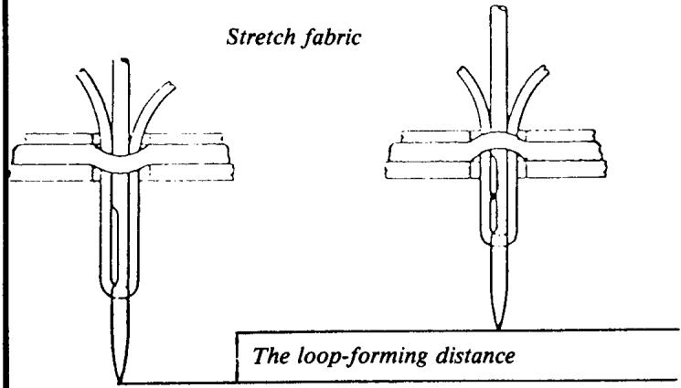
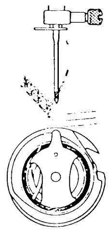
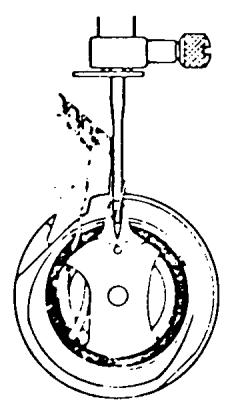
The stitch formation on a domestic (household) sewing machine is done in such a way that the needle, with the thread, passes through both layers of fabric down to its lowest position, then the needle raises 2.5mm . The thread at this stage is not stretched and, due to the friction occurring between the thread and fabric, a loop is formed in back of the needle. This loop is caught by the point of the shuttle and drawn round the whole shuttle.
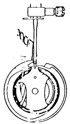
When the thread has passed the lowest point of the shuttle the thread take-up lever starts gathering the thread. The loop reduces and the upper thread pulls the lower thread up to the stitch plate. If the upper thread tension and lower thread tension are set correctly, an intertwining of the lower and upper threads occurs between the two layers of fabric. Thus, a stitch is formed.
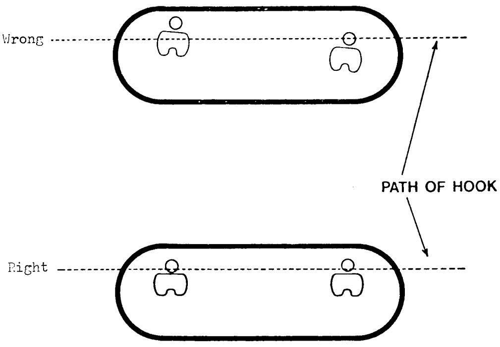
The movement of the needle going from its lowest position until the point of the shuttle catches the loop is called the loop-forming distance. At this point it is particularly important that the fabric is held flat against the stitch plate. If the fabric should be pushed down through
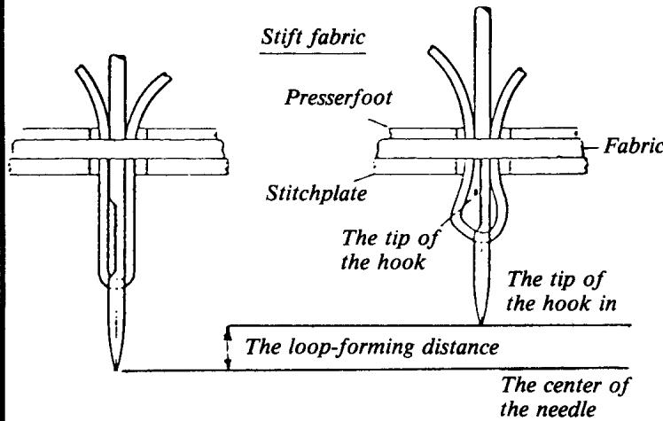
the hole in the stitch plate by the needle and pulled up again when the needle goes through the hole in the presser foot, the loop-forming distance will be correspondingly reduced and can be so small that no loop is formed at all. However, the machine is adjusted in such a way that the point of the hook shall always be able to catch the thread, even if the loop is practically nonexistent. There is a scarf in the needle, above the eye, for this purpose. The point of the hook is approximately 5/100 mm in front of the remainder of the side of the shuttle. When the needle is above the level of the stitch plate, the feeding of the fabric takes place and then ceases immediately after the thread take-up lever has drawn up the whole thread loop. During this time the hook revolves one turn-in order to be correctly positioned to catch the thread when the needle next completes a loop-forming distance.
SEAM FORMATION
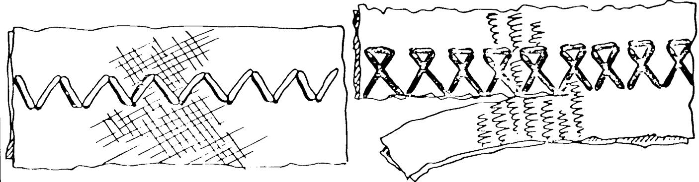
The type of stitch formation just described is used on practically all domestic sewing machines and the machines then differ in the way they form seams. The simplest seam is straight stitching, where the machine feeds forwards or backwards with the same stitch length along a straight line. Husqvarna used to manufacture straight stitch machines, but this manufacture has now been discontinued. When sewing zigzag seams, the needle moves at right angles to the direction of feeding the same length, every other stitch to the left, the other to the right. Regarding zigzag sewing machines, we have the model 6170. If the movement of the needle varies in size and direction, according to a certain program, seams of varying appearance will be produced. We have this type of seams on all specified machines, the first of which is model 6170. It is also possible to vary the feeding in size and direction, thereby obtaining additional variation possibilities. These type of seams are to be found on the machines 6270, 6370 and 6570.
Besides straight stitch and zigzag, the seams are usually divided into utility and decorative seams. Utility seams are adapted to a certain sewing operation, e.g. hemming of a skirt of a certain type of fabric such as tricot, jersey, etc. Utility seams give in such cases a certain elasticity and memory.
The decorative seams are intended to decorate a garment or piece of work.
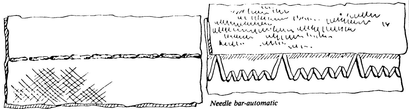
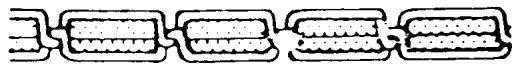
Straight stitch
Zig-Zag
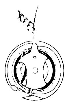
SHUTTLE SYSTEM
As mentioned earlier, the stitch formation is made by means of a needle and a shuttle system. Even if all domestic machines have the same type of stitch formation, the construction of the shuttle system can vary.
In the original type of construction, the shuttle was designed in such a way that it, together with the lower thread, moved in a straight line. However, today, all shuttle systems are designed so that the shuttle rotates around the bobin with the lower thread.
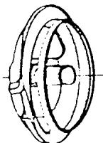
Shuttle systems can be divided into two specific types, namely those where the shuttle rotates on a horizontal level (drop-in bobbin), and those where it rotates on a vertical level, parallel with the needle (Viking).
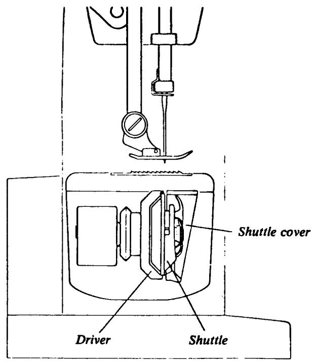
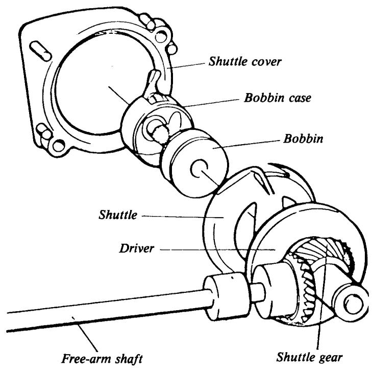
The Viking Husqvarna shuttle system is designed with a vertical, rotating hook freely suspended between the driver and the shuttle cover. This eliminates any risk of loose threads getting caught up in the shuttle. It also requires no lubrication. This system has been used in our sewing machines since the fifties and we are still the only manufacturer using this design.
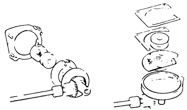
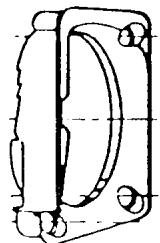
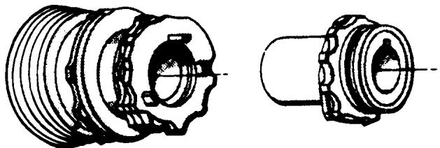
DESIGN OF THE VKING SHUTTLE SYSTEM
The driver is shaped like a dish and made of sound diminishing plastic. The shuttle lies in this dish
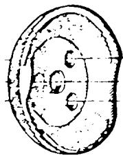
Driver
Shuttle
Shuttle cover
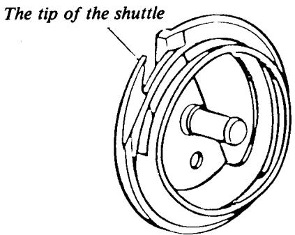
The shuttle (hook) is made of steel sheet, shaped in two halves which are soldered together. A rather soft quality of material with low carbon content is used, thereby facilitating punching. The two halves are brazed by placing a copper thread between two flat surfaces and the parts are fixed in relation to each other. The copper melts when heated to 1,1000^ , spreads out in the space and solders the two halves together. These are then milled and thereafter heat treated in an atmosphere containing carbon monoxide. The material absorbs the carbon and can be tempered. The result is a detail with very hard surfaces, while the core is still softer and ductile.
The tip of the shuttle which must absorb carbon from four sides becomes hard all the way through. The bobbin case is also shaped in steel sheet, which is then tempered and chrome-plated.
A lot of work is devoted to the shaping and finishing of the shuttle and bobbin case. Machining is, of course, done as much as possible but manual operations cannot be completely avoided. Both of these parts go through about 150 operations before they are finished.
continued
The shuttle cover is made of plastic and must be freely suspended, e.g. be able to move both axially and radially. Since the shuttle is freely suspended between the driver and shuttle cover, it must move evenly to avoid problems with high noise level. It is, therefore, necessary to devote a great deal of work when manufacturing the gear for the shuttle and the other parts, so that the path of the thread through the shuttle causes as little friction as possible on the parts.
Shuttle transmission
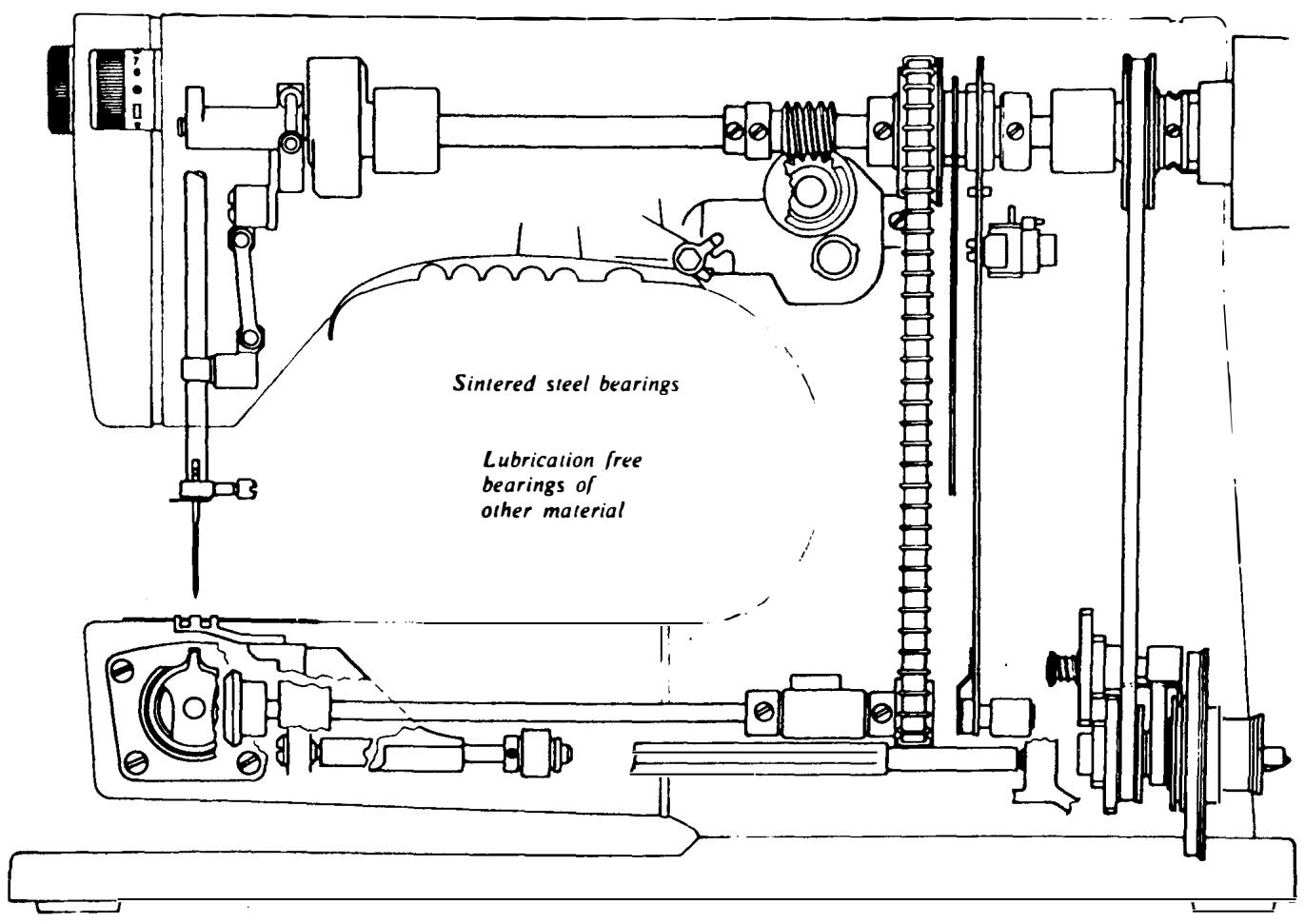
BEARINGS
The bearings for the upper main shaft and the lower main shaft are mounted in sleeves of sintered steel and the bearing arrangements in cast iron (steel) machines are produced by precision drilling. Straight, cylindrical sleeves are pressed into the precision-drilled holes. A very high degree of precision is required and tolerances here are less than 2/100 mm, i.e. less than a third of the thickness of a human hair.
Very high precision demands are also made on the shafts. The production tolerance of the diameter is 6/100mm and this has been attained by grinding the shaft. Measuring is done by using compressed air; the air must pass through a ring, in which the shaft is inserted. The resistance against the air constitutes a diameter measurement.
continued
Non-lubrication is attained by the fact that the bearing sleeves are oil-impregnated. To produce sinter steel sleeves, powder metal is pressed in a tool into a detail of the required shape. This detail is then heated in a nitrogen atmosphere to such a temperature whereby the small particles of metal melt on the surface and adhere to each other. This method ensures that very high precisioned, stable parts are produced but the material is porous. It is these pores that act as reservoirs for oil.
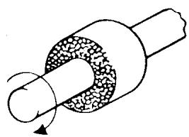
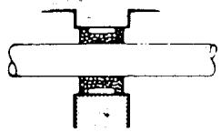
The rotation of a shaft in a sintered steel sleeve will generate some heat on account of the friction. the wall of the sleeve is also subjected to pressure. Consequently the oil gets warmer and expands, i.e. is forced out of the pores in the sleeve
and lubricates just at the point where it is best needed. When the machine is then switched off and the bearing sleeve cools, the oil returns to the pores.
To ensure maximum operational reliability we use a special oil. This oil has to meet very stringent demands regarding its consistency when in contact with the surrounding atmosphere and on its viscosity properties when returning to the pores after each time the machine is used. This type of bearing has been tested by us during a period of 12 years, under very stringent conditions from the point of view of climate and operation. They have met these very high demands. Sintered metal is used for the bearings, as is the case with many other parts in the sewing machine mechanisms, where good bearing properties are an advantage.
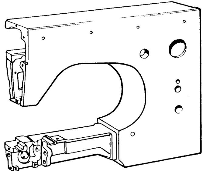
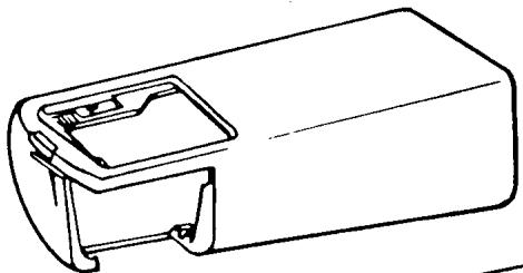
THE SEWING MACHINE FRAMES
The sewing machine is built up around a frame which can be designed in several different ways. However, in all versions, the needle moves down through the stitch plate to the shuttle, where the stitch is formed. There is a space to the right of the needle which should be designed so that the part of the garment which is on the right-hand side of the seam can be moved forwards. A necessity for good sewing results is that the frame
is stable and that the needle is always correctly positioned in relation to the stitch plate and shuttle. A flat-bed machine is generally designed in such a manner that the upper arm is screwed to the bed. The same applies to most free-arm machines when the upper arm is screwed to the free-arm. The frame of Husqvarna machines is cast in one piece, e.g. the upper arm and free-arm consist of one piece only.
continued
THE FRAME OF HUSQVARNA SEWING MACHINES
Husqvarna manufactures sewing machines in two materials, namely of cast iron (steel) and aluminum alloy.
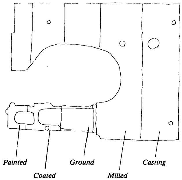
The cast iron frames are produced by means of shell moulding, where the mould is built up of phenol-impregnated sand. The mould is then placed in a frame. By using this method, it is possible to produce homogeneous castings with thin walls and smooth surfaces. In addition to this, the whole of the outside of the machine is ground, to ensure absolutely smooth painted surfaces and a high grade of adherence between the enamel and the iron. The mould can only be used once.
The aluminum alloy is cast, without pressure, in a steel mould with a core of sand. The core is destroyed but the steel mould can be used for 20,000 castings. This casting is also machined on the outside, mainly by milling. By using these methods, it is possible to produce bodies of rather complicated and closed form and the castings have good damping properties.
All these frames are cast in one piece, e.g. the free-arm and the rest of the machine body consist of one piece only.
PAINTING OF THE FRAME
The frames are painted in an electrostatic plant, where the paint is pumped up to a rotating plate. The paint particles are charged to a voltage of 80,000 volts and scattered into the air by the centrifugal force. The sewing machine frame is grounded and therefore attracts the charged paint particles. This method produces very even distribution of the paint, even over complicated surfaces. All details are painted two or three times and hardened for 20 minutes between each painting at a temperature of 120^ .
THREAD TENSION
LOWER THREAD TENSION
The lower thread tension is controlled by the thread tension spring on the bobbin case. The thread tension is set in a spring-balanced fixture to a rating of 22 g. (This setting is
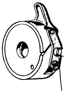
Thread tension spring
not altered during the assembly of the machine). This operation is done to attain the highest degree of uniformity between the bobbin cases. A problem in this connection is the varying qualities of thread which cause different resistance. All machines were previously set with cotton thread. Now synthetic thread is used. Cotton thread is affected by the humidity in the air and varying frictional conditions occur in different climates. Synthetic thread does not absorb moisture, but even synthetic threads vary, depending on how they were treated before being wound on a thread spool.
continued
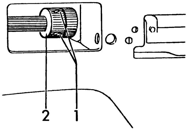
UPPER THREAD TENSION
The upper thread tension is controlled at the thread tension device. This is completely built into the face plate and located in a way that the thread can naturally be threaded between the thread tension discs. Even here, the thread tension intensity is pre-set so that
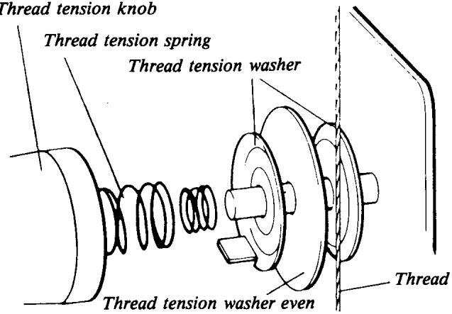
Thread tension knob
a certain rating can be obtained at the red dot on the thread tension knob. This tension is adapted to balance the lower thread tension when sewing cotton fabric of normal quality and with the thread supplied with the machine.
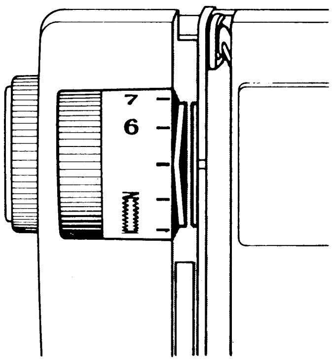
We have endeavoured to have the machines set as uniformly as possible and a thread tension which is as versatile as possible. However, there are many personal opinions regarding
thread tension. Fabrics used on certain markets can also differ from what we consider most usual. Unfortunately it is a fact that many customers feel bound to use the setting obtained at the red dot. Under certain conditions it can, therefore, be appropriate to alter the tension at the red dot. This is easily done by altering the outer ring on the tread tension knob.
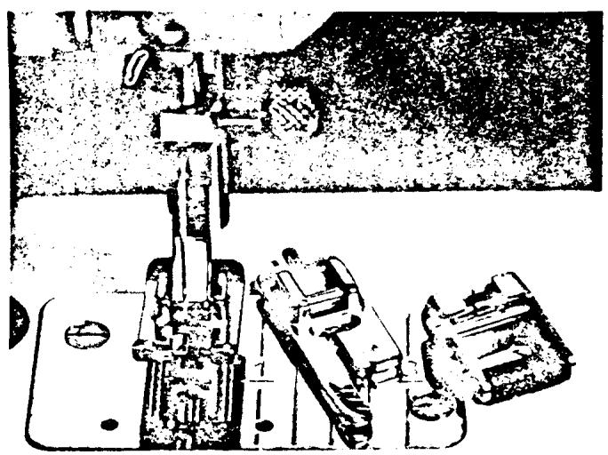
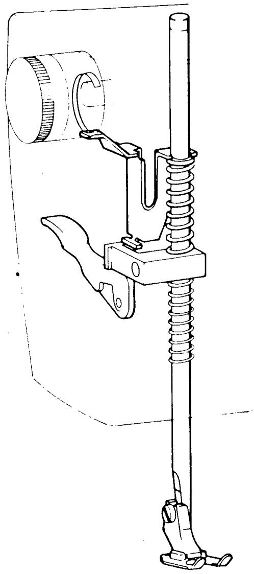
HOLDING THE FABRIC IN PLACE
It was pointed out when talking about stitch formation how important it is to hold the fabric flat during the movement of the needle. To attain this, presser feet are used, which press the fabric against the stitch plate. Different sorts of presser feet are used for different types of sewing and they have, therefore, been designed to be easy to change. They consist of an attachment and a sole, where only the sole is exchanged. The presser foot pressure can also be adapted to different types of sewing or fabric. By turning the knob at the front of face plate cover, the spring for the presser bar pressure is influenced, either to increase or reduce the presser foot pressure.
THE DRIVING OF THE MACHINE AND ELECTRIC SPEED REGULATION
ELECTRIC DRIVE
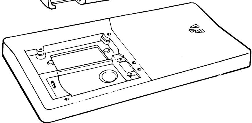
The sewing machine is driven by an electric motor which is rubber mounted in the base plate to prevent sound from the motor being propagated in the
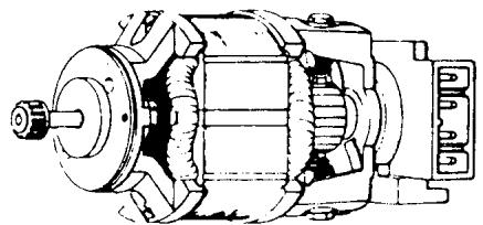
machine. It is double insulated and connection to a wall socket is done by means of a two-wire system and a universal plug. It is supplied with built-in electrical components making the whole equipment radio and TV-suppressed according to applicable international regulations.
As far as electric motors are concerned they are the absolute best quality to ensure that the machine operates reliably and to reduce service costs.
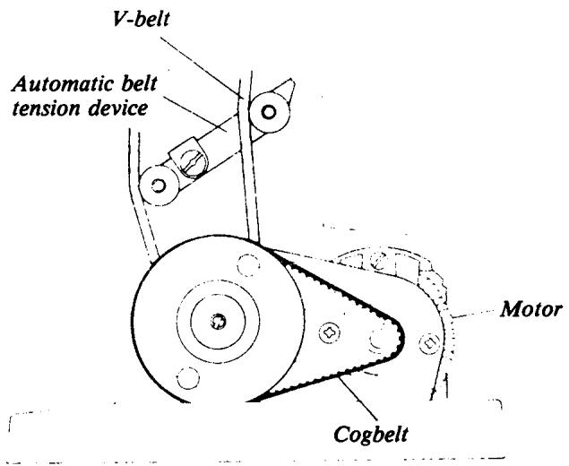
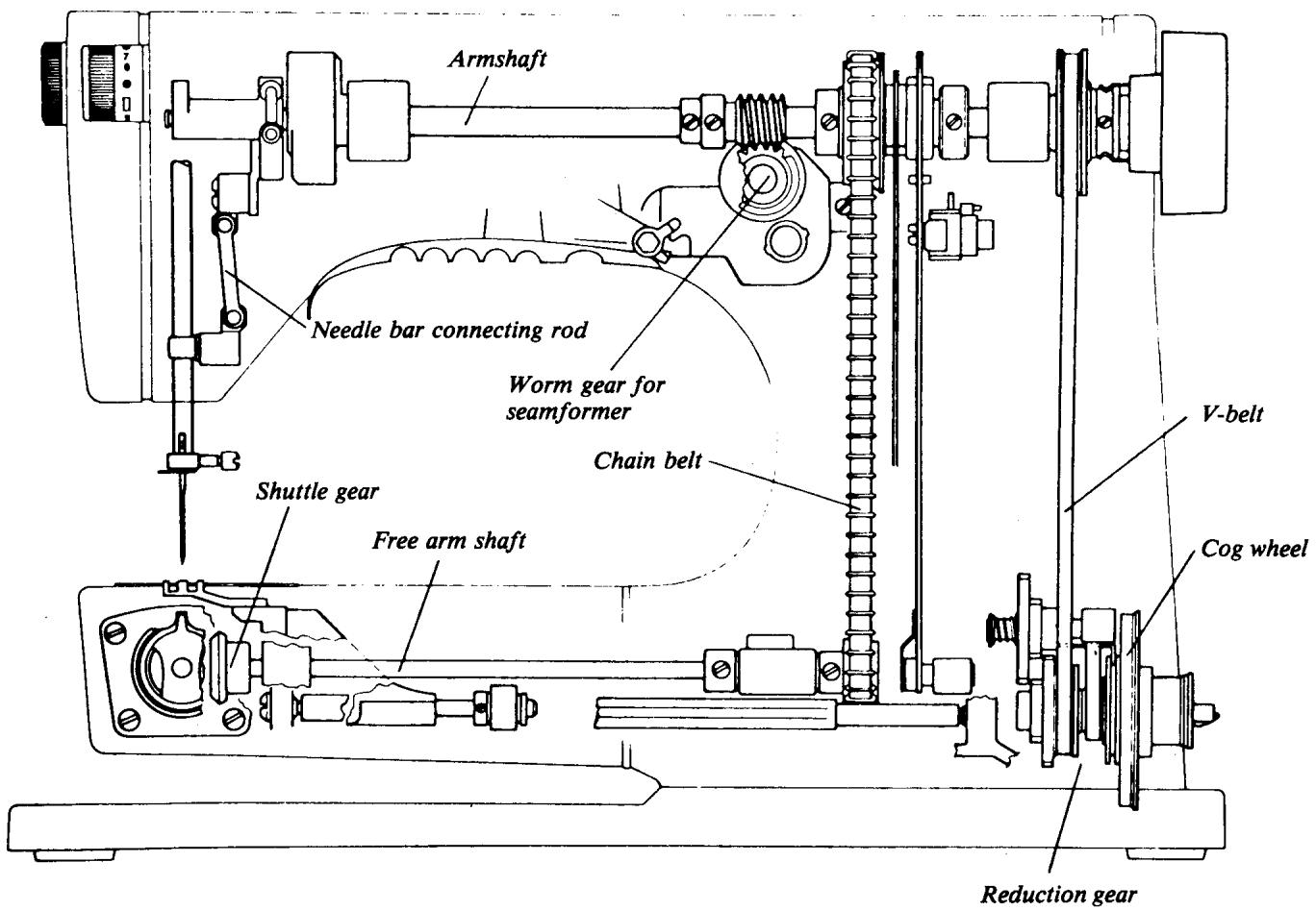
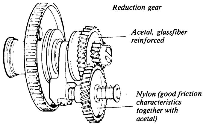
POWER TRANSMISSION
The power is transmitted from the motor by means of a cog belt to a reduction gear, which is adjustable and allows a reduction in the speed of one-fifth. There is a V-belt between the reduction gear and the main shaft, enabling a certain elasticity in the transmission. However, there is a built-in belt tension device to eliminate slipping and to compensate for possible wear of the V-belt. This consists of two belt idlers; it sets itself automatically to increase the belt pressure against the belt wheel when the needle meets a harder resistance.
continued
Synchronization between the main shaft and the free arm shaft is done by means of a chain belt. The seam former is driven by a worm gear which works on the main shaft, while the shuttle gear is driven by a bevel drive.
A lot of work has been devoted to making the machine as reliable as possible, both as regards the structural design of the machine and the manufacture of the various parts.
SPEED CONTROL
There is a main switch on the belt guard which controls the electric current to the motor, printed circuit and light bulb. As long as the electricity is disconnected there is no risk of the machine starting if the foot control should be inadvertently depressed. The lamp can be used as an indicator as to whether or not the electric current is connected.
The speed of the machine is regulated by a foot control, which is connected to the electronic equipment built into the machine. The foot control is designed to give support to the whole foot. When the control is depressed, a low current passes through it, regulating the speed of the motor.
Full current is available all the time to the motor and as very little of the current is consumed by the foot control, there is an extremely low energy loss and no buildup of heat.
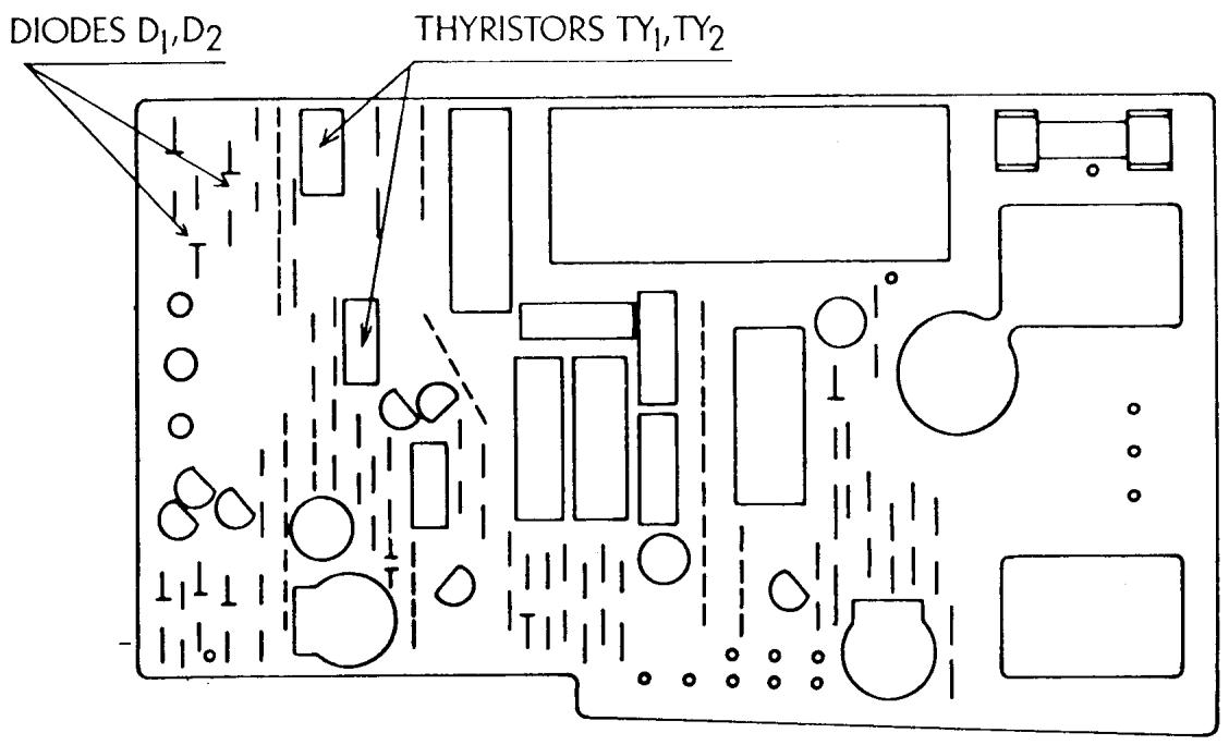
The electronic equipment converts the alternating current from the power supply to pulsating direct current by means of the components D_1 and D_2 (diodes) and this in turn regulates the motor via Ty_1 and Ty_2 (thyristers). There are also circuits which give the motor more current if the needle meets harder resistance. Due to these circuits it has been possible to greatly increase the needle power and thereby the penetr-
continued
tion capacity. Compared to a machine with resistance control the increase is doubled or trebled at low speed. This enables the machine to be kept at an even, low speed, independent of the load.
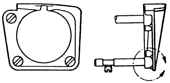
SETTING THE STOP-RIGHT POSITION OF THE NEEDLE
To enable the finished work to be removed from the machine without the lower thread being hindered by the shuttle, it is necessary that the needle is at its upper position. In the same way the needle must be free from the fabric when changing a seam or movement in button-holing. In some cases it may also be important that the needle remains at its lowest position, e.g., if a sudden change of direction in a seam is necessary. In these cases it is a great help if the needle stop-right position can be set and this may be done by using the stop-right pushbutton, located on the belt guard. By pressing in the upper part of the pushbutton the needle will stop at its highest position and when the lower part is pressed in, the needle will stop at its lowest position. When the pushbutton is at the center position, the needle will stop at any position.
The stop-right function is attained by a metal screen, which is built into the handwheel, actuating a magnetic switch. When the foot control is released the regulated current cuts out, and only the current through the electronic circuit conveys the needle to the required stopright position. If the needle meets such hard resistance that the machine jams, the current to the motor cuts out automatically after 5 seconds.
OTHER MATERIAL
Most of the small details (parts) of the sewing machine are made of steel or steel alloys with different grades of tempering. However, quite a lot of the details in the mechanisms are made of die-cast aluminum. In addition, there are some details which must have good bearing properties and wear resistance, which are made of different sorts of plastic.
On the subject of plastic, it is important to distinguish between the type of plastic used in design details and the type used for inexpensive packing and throw-away wrappings. The constructional plastics have completely different properties and are considerably more expensive. If a detail, e.g., a cog wheel or a programmer, is made of plastic, it must have advantages over metal - e.g., a cog gear will function more smoothly
and quietly; a cog gear or programmer will have more wear resistance. If the programmer is made of metal it will wear much quicker, even when using the best special steel, as long as the properties are not changed completely by means of an oil bath or the like.
continued
Husqvarna manufactures many details in their own plastics machines but a good deal of the larger details are bought from specialist manufacturers. The processing is done by spraying the molten material into closed steel tools, which have a cavity corresponding to the shape of the detail. After a certain cooling time, the tool is opened and the detail is in its final shape. Sometimes, even certain plastic details must be machined to attain sufficient precision. The programmers are bought from a specialist manufacturer as workpieces and then machined, first in the hole and the end face. The cams for the needle bar movement are cast in the final measurement with a precision of ± 5% mm. The cams for the feeding movement must be of even higher precision. These are, therefore, machined by scraping with a precision of ± 2% mm. The steering worm gear and the gear for the shuttle are machined on the outside and also the cog is cut by machining.
Acetal (good wear resistance, low friction)
Special steel
PATTERN MECHANISM
The most advanced mechanism in the machine is the pattern mechanism.
which is actually a programme works for the position of the needle and for determining the size and direction of feeding. When turning the knob, both cam followers should be lifted from the cam and the fixed cam and programmer moves axially. To facilitate the setting, a cog gear has been designed, so that the knob is turned half a turn between each indexing.
The movement of the fixed cam is activated from the main shaft and is synchronized to the movement of the needle. The cam followers then sense the different radius positions on the respective cam and transfer the movement to its mechanism.
Cam follower for the reverse lever Fixed arm cam
Cam follower for needle bar movement
continued
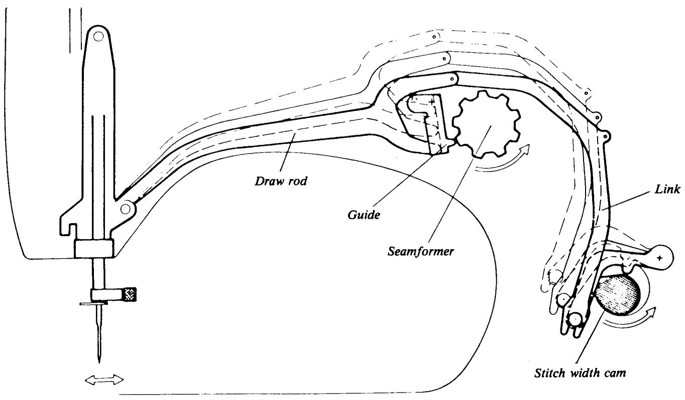
MOVEMENT OF THE NEEDLE BAR
The pattern mechanism is built up in a frame with horizontal shafts which support the fixed cam and cam follower. The cam follower for the movement of the needle bar has its point of suspension slightly to the left of the fixed cam. By means of the stitch width knob, the position of the draw rod in the guide of the cam follower can be set.
As the fit-up point of the draw rod is in front of the turning center of the cam followers, there is no side movement of the needle bar, i.e., the machine sews straight seams. When the draw rod is moved downwards, a side movement of the needle bar is obtained. The curve of the cam then determines the reciprocal size of the sideways deflection of the needle bar.
MOVEMENT OF THE FEED DOG
There are two eccentrics behind the wheel of the synchronizing belt. By means of a connecting rod and a feeding shaft, one of the eccentrics produces the height
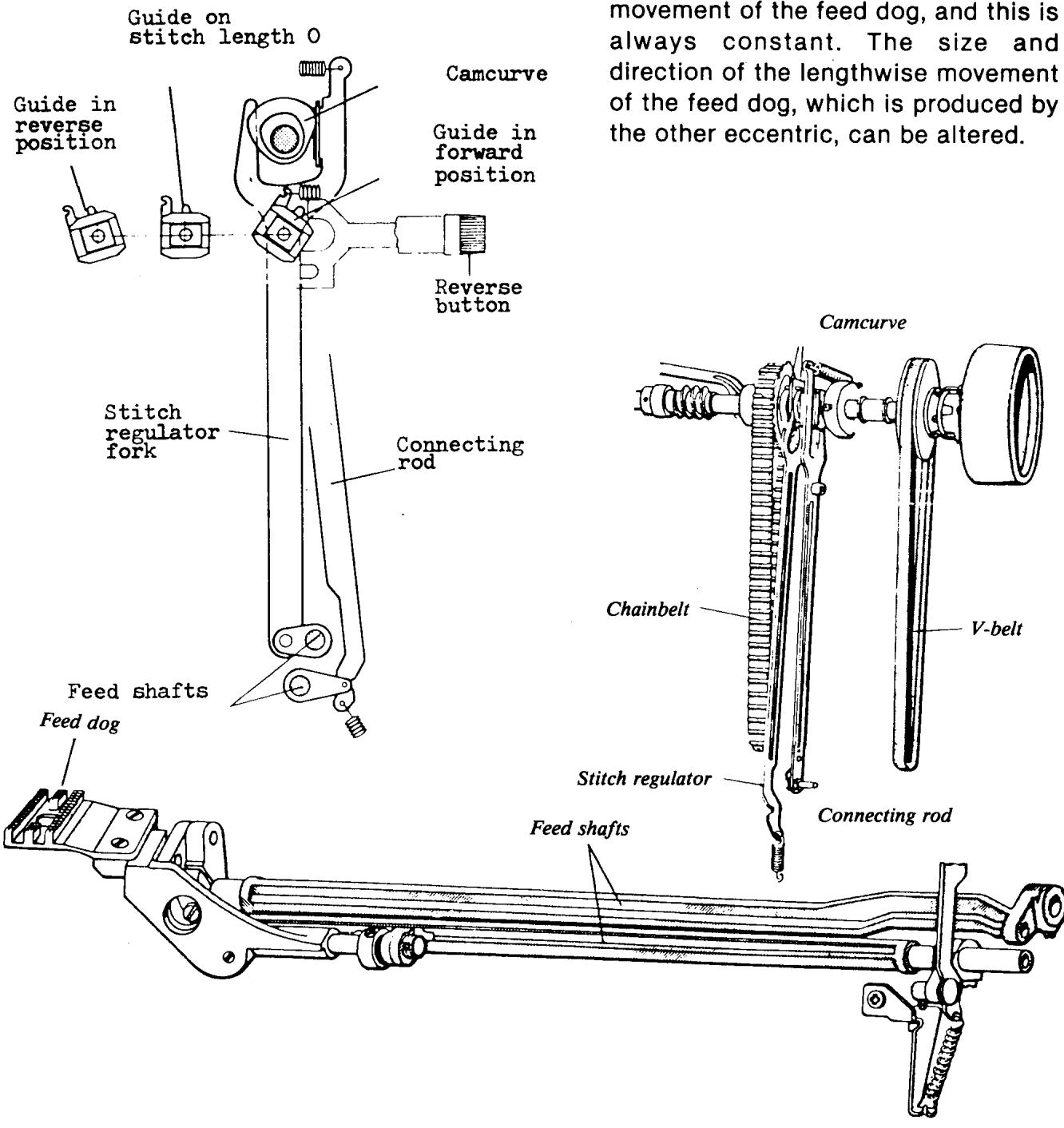
continued
This depends on how the guide in the stitch length mechanism is set. This guide is set by means of the stitch length knob and the machine then sews a seam with constant feeding. However, if the pattern mechanism is set at a feeding pattern, the cam follower for the automatic feeding is affected so that the size and direction of the feeding changes between each stitch. This adjustment must take place when the feed dog is under the level of the stitch plate. It is, therefore, important that the seam former is synchronized in relation to the movement of the feed dog, i.e., over the main shaft.
It is possible to make adjustments on the pattern mechanism for the lifting height (retraction) of both cam followers, for the center needle position, and the relationship between the left hand needle position and the zigzag position. In addition it is possible to adjust the relation between forward and reverse feeding when sewing patterns. The machine can be adjusted in such a way that the needle returns to the same position as it had previously after a part of the pattern.
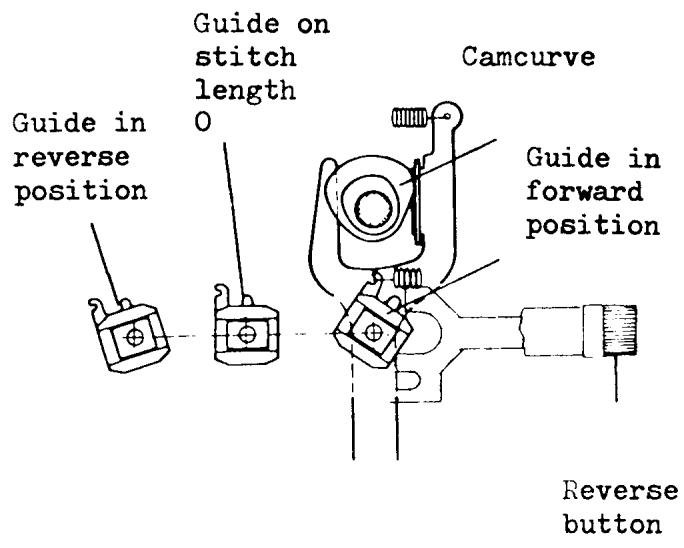
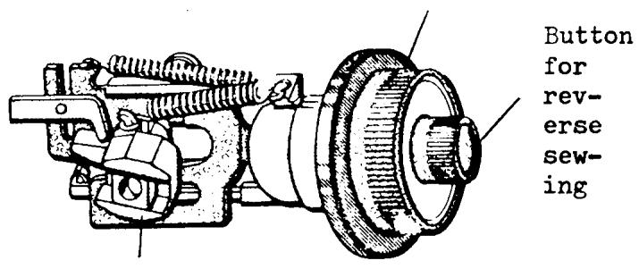
STITCH LENGTH MECHANISM
As mentioned under the description of the pattern-mechanism the lengthwise movement of the feed dog, i.e., the stitch length, is effected by the setting of the guide in the stitch length mechanism. This guide is set by means of the stitch length knob which has two axial curves which decide the angular position of the guide. The foremost curve is coupled at normal sewing and the rear curve works as a stop when the reverse feeding button is depressed. Reverse sewing using the reverse feeding button is usually used for locking the thread, so the curve is not completely symmetric with the curve for forward feeding and the button will not lock. By means of an adjusting nut in the reverse feed button, the relation between forward and reverse feeding can be adjusted. This adjustment nut is where the buttonhole column equalization is adjusted.
Stitch length dial
BUTTONHOLE MECHANISM
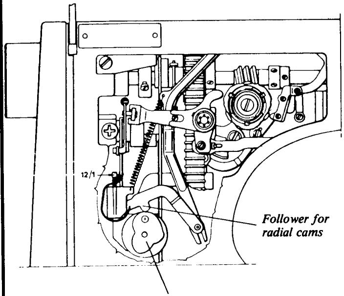
Radial cams
The stitch width is set from the button-hole mechanism and also the different buttonhole moments. The main shaft of the mechanism is equipped with two radial curves at the rear part. One is a spiral curve which makes continuous adjustment of the stitch width possible. The other one, which is coupled when the knob is pulled out, i.e., the button-hole automatic, when coupled has four different positions. These are adapted to produce suitable stitch widths for the different steps when sewing button-holes.
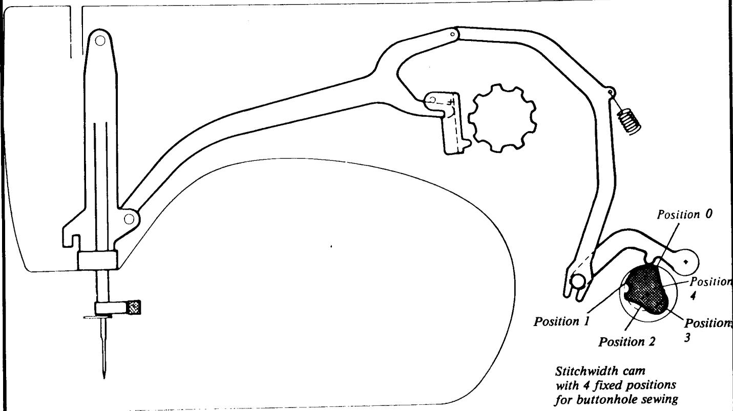
continued
There is an axial curve nearer to the knob, which is coupled when the button-hole automatic is used, and this determines the direction of the feeding when sewing buttonholes.
There is also a press-button below the buttonhole automatic, for disconnecting the feed dog, i.e., drop-feed button.
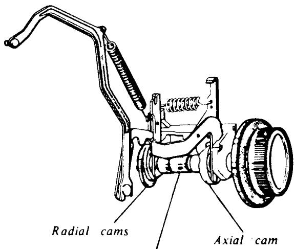
Main shaft
REMOVING COVERS FOR MACHINE SERIES 70, 60, 40
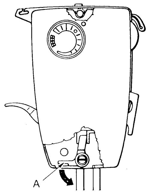
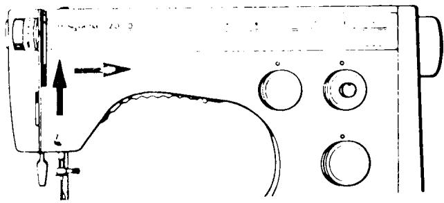
I. FACE PLATE SHELL
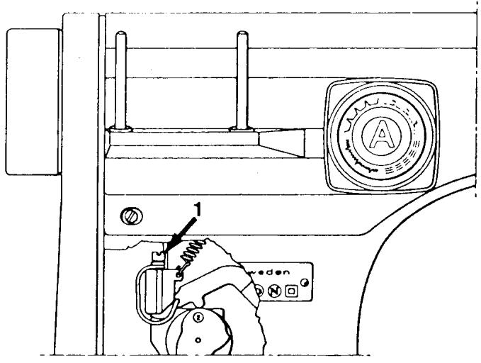
Push latch (A) downwards and remove the lower part of the face plate shell from the machine. It's then possible to lift the shell upwards, releasing it from the upper fastening screw. Remove the shell.
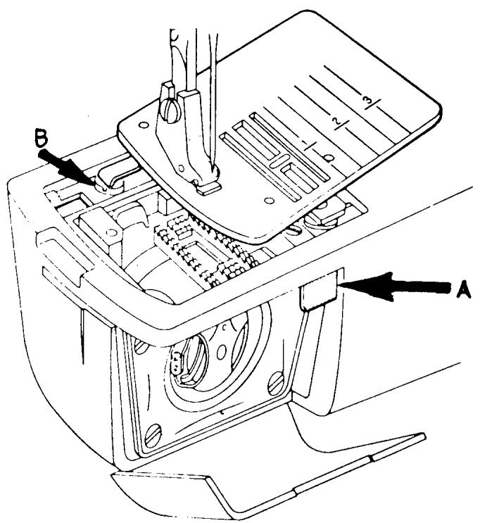
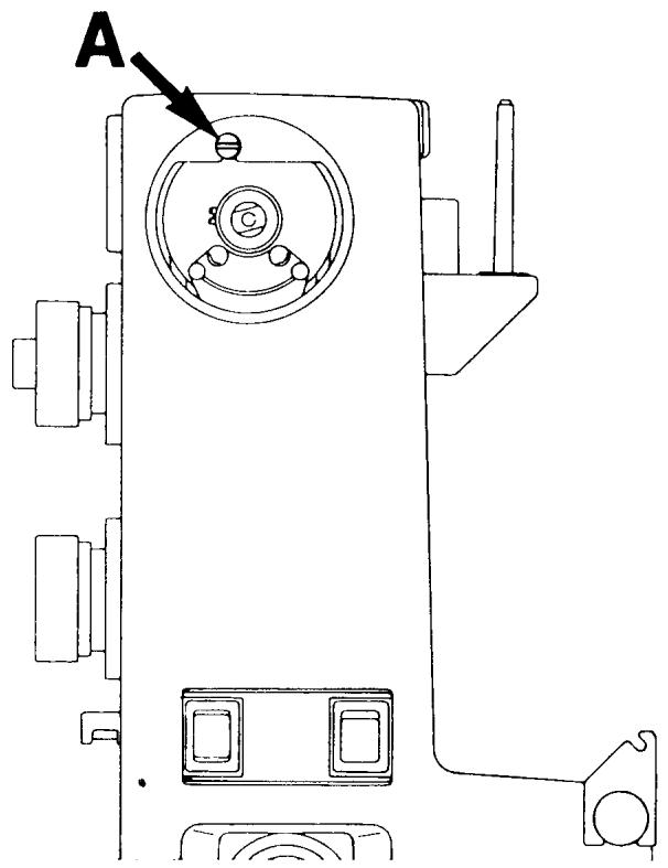
II. ARM SLEEVE
Release the stitch plate by pressing key (A), the remove. Drop the feed teeth. Remove screw (B) and slide the arm sleeve off the open arm.
COMMENT
When installing the stitch plate, put the arm sleeve on and moderately secure the screw (B). Install the stitch plate and check to see that it pops up when key (A) is pushed. Remove plate and secure screw (B).
REMOVING COVERS FOR MACHINE SERIES 70, 60, 40
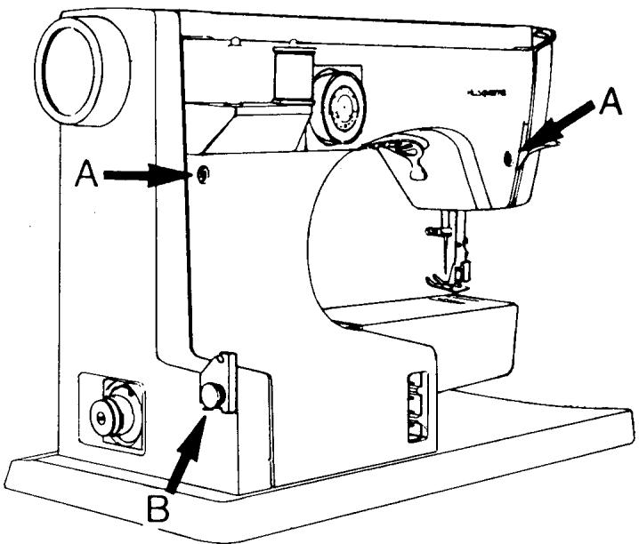
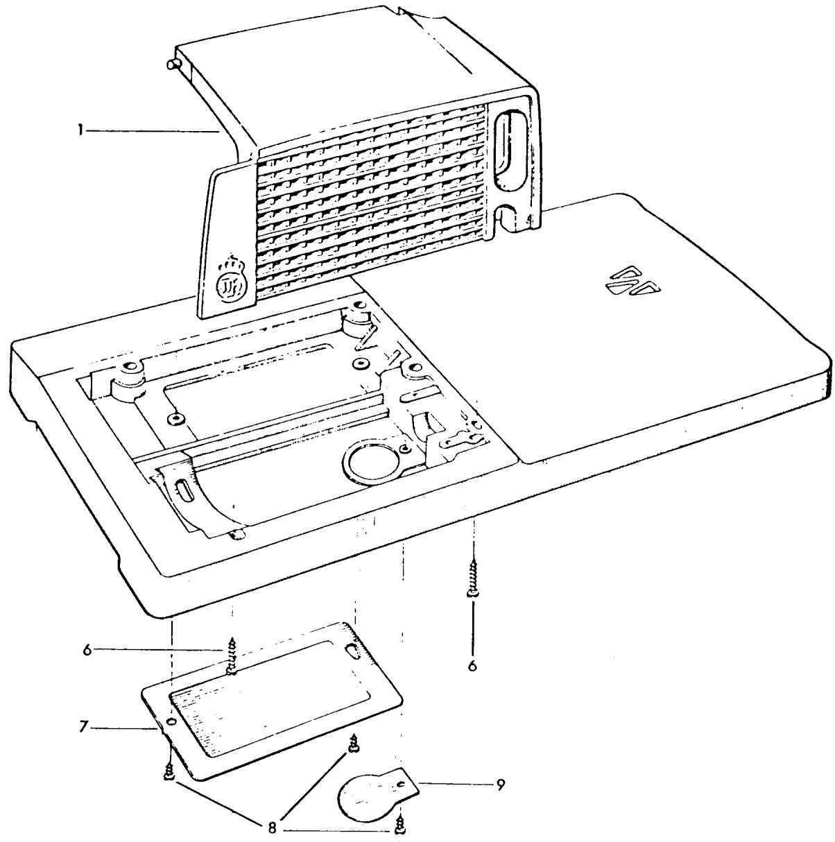
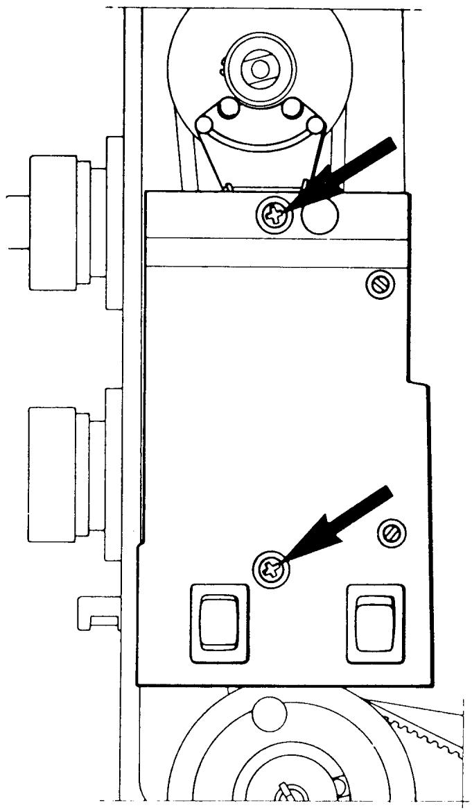
III. BACK COVER
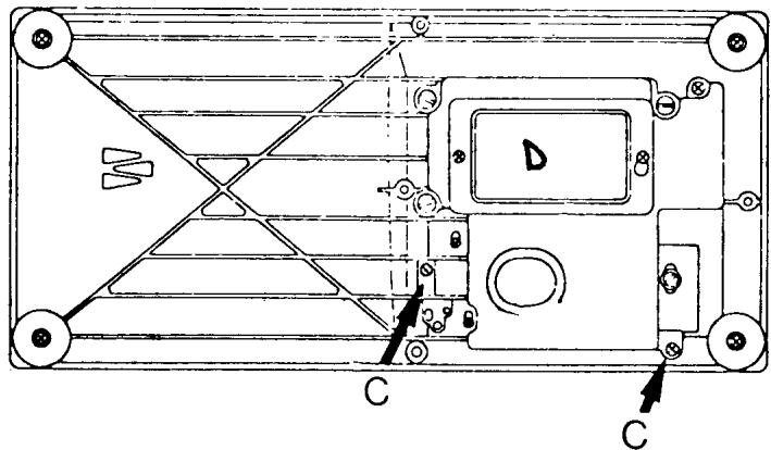
Take away the programmer and remove the two screws (A). Snap off the bobbin winder cap and remove screw (B) which is underneath the bobbin winding thread guide. Lay the machine on its back and remove the two screws (C). Remove the back cover.
COMMENT
On the latest series machines the two screws (C) will be absent. They have been replaced by a nylon stud and an integrated locking tab which fits under the terminal block.
NOTE This is a good time to open the inspection plate (D).
REMOVING COVERS
FOR MACHINE SERIES 70, 60, 40
IV. BELT GUARD
70 Series
Rotate the handwheel until the thread take-up lever is in its lowest position. Remove the mounting screw in the middle of the handwheel and then remove the handwheel. Remove screw (A) and the belt guard can easily be taken away.
NOTE Notice the eccentric adjustment screw in the bottom of the belt guard. Turning this adjustment screw will align the belt guard parallel to the frame of the sewing machine.
60 and 40 Series Machines
First, pull off the handwheel, then take hold of the belt guard and see if it will come away. On some earlier models it may be necessary to lay the machine on its back and remove the Phillips screw in the upper right corner. Then it will be
possible to remove the belt guard.
V. PATTERN SCALE
Lift out at the upper left corner, and firmly shift the scale to the right to snap it off.
NOTE The pattern scale must be re
moved to make it possible to
adjust the needle positions, i.e., centering the zigzag in the stitch plate and centering the needle front to back in the stitch plate.
REMOVING COVERS
FOR MACHINE SERIES 30, 20, 10 AND EARLIER MODELS
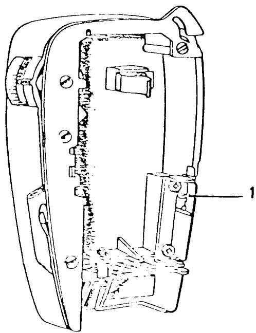
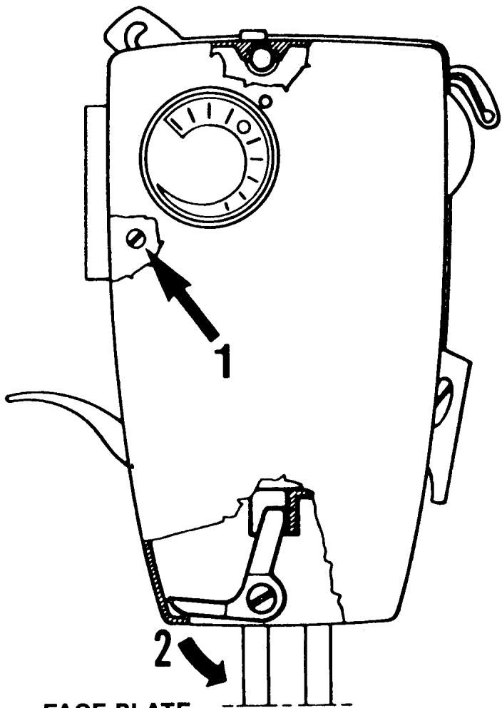
I. FACE PLATE SHELL
30 Series
The latch (2) located under the lower edge of the face plate shell should be drawn downwards and the lower part of the shell lifted out from the machine. The cover can now be lifted upwards, so that it releases from the upper shoulder screw.
COMMENT
Screw (1) which secures the edge of the back cover should now be removed.
FACE PLATE
10 Series
Open the cover and push in catch (1). This is best done with the tip of a screwdriver. Lift the cover up and remove it from the machine. Loosen the Phillips screw securing the release tab (20 series only).
REMOVING COVERS
FOR MACHINE SERIES 30, 20, 10 AND EARLIER MODELS
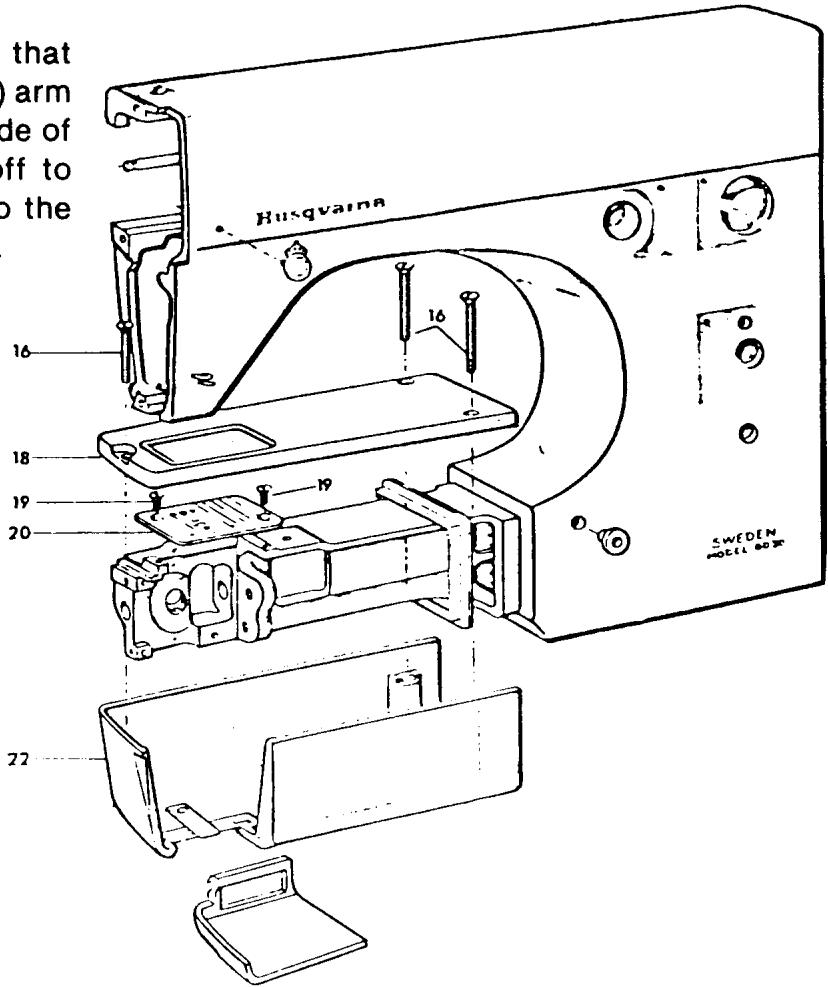
II. ARM COVERS,
UPPER AND LOWER
Remove the three screws (16) that hold the upper (18) and lower (22) arm covers on. Lift up on the right side of the upper cover, then slide it off to the left. Slide the lower cover to the left and away from the free arm.
COMMENTI
On some models, screws (16) come in two different lengths. Observe if this might be the case, and if so, remember which arm sleeve hole they go in.
COMMENT II
By removing screws (19) the stitch plate can be removed. The feed teeth are now available to clean.
REMOVING COVERS
FOR MACHINE SERIES 30, 20, 10 AND EARLIER MODELS
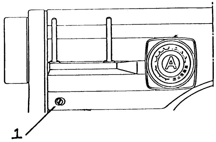
III. BACK COVER
Remove the programmer from the machine. Loosen and remove screw (1). Slide the back cover to the left and remove.
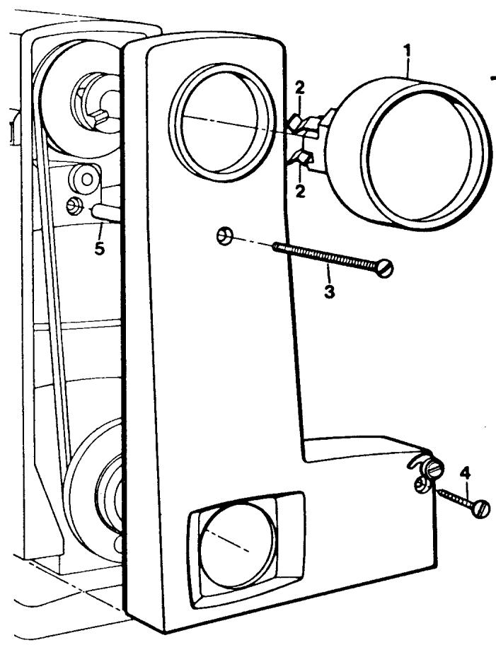
IV. BELT GUARD
The handwheel (1) is attached to the pulley by two springs (2). Pull the handwheel off. If necessary, insert two screwdrivers (between the handwheel and belt guard) and with equal pressure pry the handwheel off. Remove screw (3) and screw (4). The belt guard can now be taken away.
NOTE The distance sleeve (5) is now loose and should be put with the belt guard.
REMOVING COVERS
FOR MACHINE SERIES 30, 20, 10 AND EARLIER MODELS
V. MOTOR COVER
The motor cover (1) can be taken away after removing the two screws (6).
COMMENT I
Remove the inspection plate cover (7) by removing the two screws (8).
COMMENT II
Remove the cover (9) for the lower motor brush by removing screw (8).

THE STITCH PLATE
REQUIREMENTS
The stitch plate must not be damaged in any way. Particular attention should be made regarding damage or unevenness around the needle hole.
ACTION
Exchange the damaged stitch plate.
COMMENTS
A stitch plate not level around the needle hole opening will affect stitch formation, usually resulting in skipped stitches. Also, needle strikes and burrs on the stitch plate will snag material.
41 15 628-01
41 11 555-01
PRESSER FOOT
REQUIREMENTS
There should be no damage to the thread slot and no scratches or burrs on the underside of the presser foot.
ACTION
Exchange the presser foot if any damage is noticed.
COMMENTS
How the fabric is held between the presser foot and stitch plate plays an important role in stitch formation. Damage to the underside of the presser foot or the thread slot directly affects stitch quality.
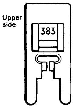
Zig-zag presser foot 41 11 383-01
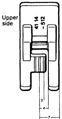
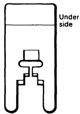
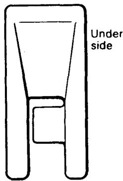
Utility stitch presser foot 41 14 512-01
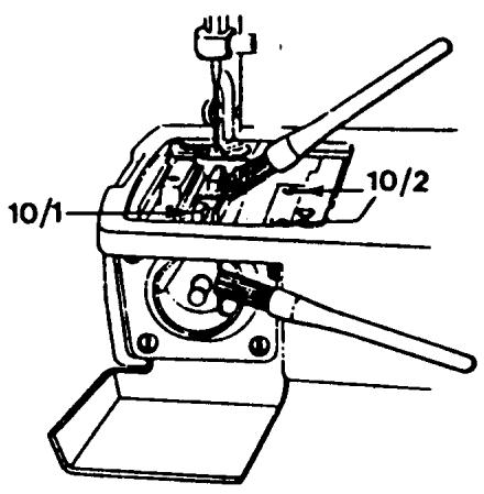
THE FEED TEETH
REQUIREMENTS
The upper side of the feed teeth (10/1) must not be damaged in any way. The feed teeth should be free of any lint, fluff and pieces of thread.
ACTION
Faulty feed teeth should be exchanged. Dismount the stitch plate, remove the screws (10/2) to exchange the feed teeth. The new feed teeth must be aligned parallel to the slots of the stitch plate.
COMMENT
When examining the feed teeth look closely at all four corners to determine if they are chipped or cracked. If damaged the material may be snagged. Also inspect the points of the feed teeth. If they have come in contact with the presser feet they may become dull. This will result in an uneven stitch length and puckering of the fabric.
THE SHUTTLE COVER
REQUIREMENTS
The inside and bridged area of the shuttle cover must not be damaged. When mounted on the shuttle posts the cover must have both axial and radial movement.
ACTION
Exchange the shuttle cover if it is damaged. Check to see that the shoulder screws and posts are not damaged. The shuttle cover clearance must be checked.
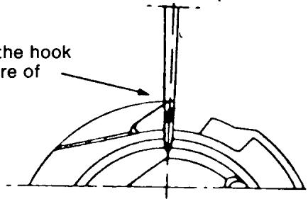
COMMENT
The inside of the shuttle cover is the support for the hook (shuttle), the bridged area on the shuttle cover supports the thread, so that the thread loop is formed on the correct side of the needle. If the bridged area is damaged the shuttle cover must be replaced.
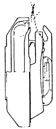
SHUTTLE (HOOK)
REQUIREMENTS
The outer edge of the shuttle must not be damaged. The point of the hook must be sharp.
ACTION
If the outer edge of the hook is damaged, it may be honed or polished. If the hook point has been damaged it is not possible to make a correction; the shuttle should be exchanged.
COMMENT
If the hook point is damaged from contact with a needle without a scarf, the hook point will become rounded. Instead of picking up the lower thread, it will push it away, resulting in skipped stitches. When the hook point is properly shaped, it will pass between the needle and thread, completing the stitch.
40 11 521-01
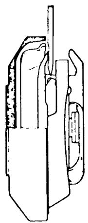
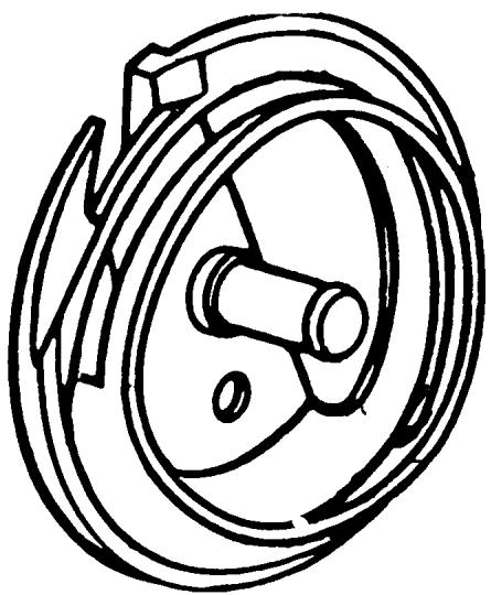
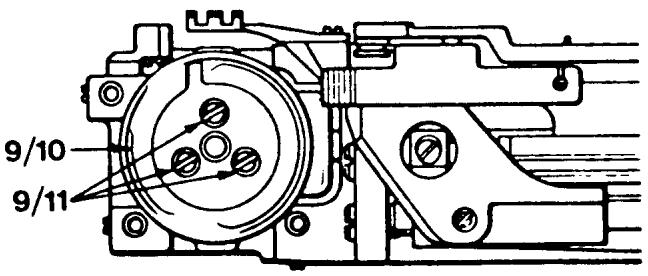
THE DRIVER
REQUIREMENTS
The outer edge of the driver and the surface of the driver against the hook must not be damaged, worn or uneven in any way which might hinder the passage of the thread.
ACTION
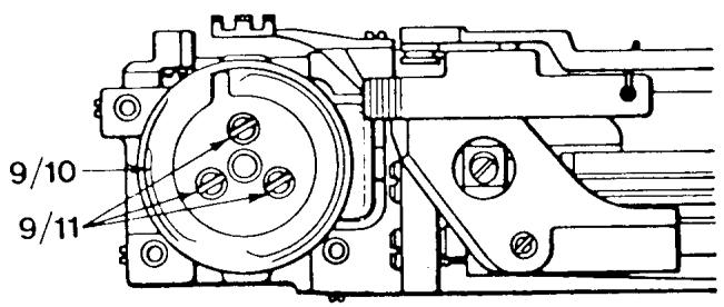
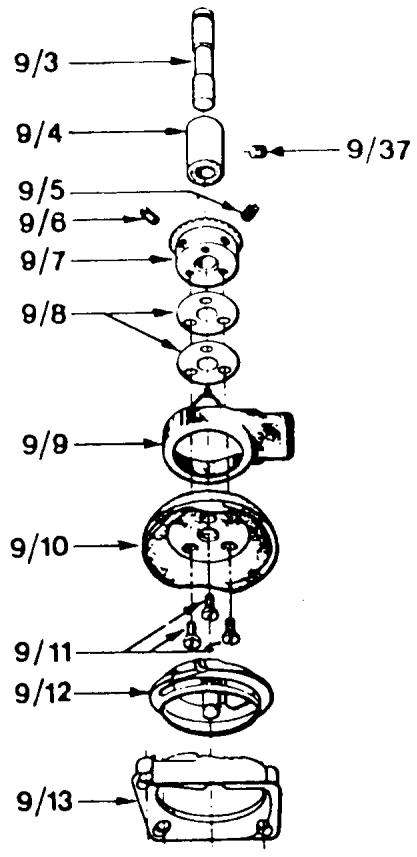
The damaged driver (9/10) should be exchanged. Turn the handwheel until the needle is in its highest position. The slot in the driver is now in the middle underneath the feed teeth. Remove the three screws which hold the shuttle cover — lift away the shuttle cover and hook. Then remove the screws (9/11) in the driver, and exchange it for a new one. Note the position of the slot in the driver. The following adjustments must be checked: needle to hook clearance, shuttle cover clearance, timing of the hook.
COMMENT
When exchanging the driver it is necessary to note the position of the slot in the driver and position the new driver in the same way. If this is not done it is possible to install the new driver incorrectly which will cause the hook timing to be extremely out of adjustment.
41 16 415-01
STITCH PROGRAMMERS
REQUIREMENTS
The programmers or fixed cam must not be damaged in any way.
ACTION
Damaged programmers or fixed cams should be exchanged.
COMMENT
Examine each lobe of the programmers and fixed cam for grooves, nicks or burrs. The prongs on the programmers should be inspected. A broken prong may alter the stitch pattern formation and increase the noise level of the sewing machine.
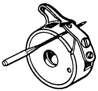
THE BOBBIN CASE
COMMENT
Thread lint and fuzz will adhere under the thread tension spring which causes the thread tension to change. Remove it by inserting a needle between the thread tension spring and bobbin case.
Check the chrome around the bobbin case; there should be no peeling. If this is noticed the bobbin case should be exchanged.
If damage has occurred to the (32) latch spring, (31) latch, (34) the thread tension spring, (36) or the thread tension adjustment screw, the individual parts should be replaced.
40 11 530-02
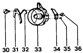
30) 41 10 601-01
31) 40 11 535-02
32) 40 11 536-01
33) 40 11 531-02
34) 40 11 781-01
35) 2286 200-01
36) 2071211-01
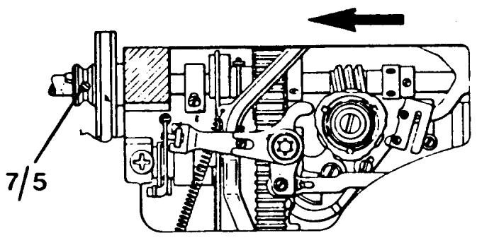
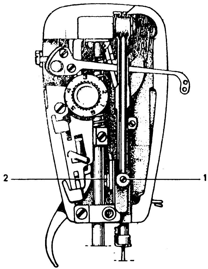
UPPER MAIN SHAFT
REQUIREMENTS
The upper main shaft should run freely during its rotation. There should be no binding and no end play.
ADJUSTMENT
Set the thread take-up lever in the lowest position, remove the handwheel and then take away the belt guard. Loosen the stop screws 7/5 on the belt wheel. Turn the seam former with one hand in the direction of the arrow and push the belt wheel in the opposite direction. Then tighten the stop screws, commencing with the one which is touching the milled plate (flat spot) on the arm shaft. Check that the arm shaft runs freely during the whole turn and that there is no axial play. When replacing the handwheel on model 6570, make sure that the thread take-up lever is in the lowest position and that the indication plate on the handwheel points upwards.
COMMENT
If there is end play in the upper main shaft there will be a knocking sound when zigzagging.
To make this adjustment on models 21 and 51 see the following page.
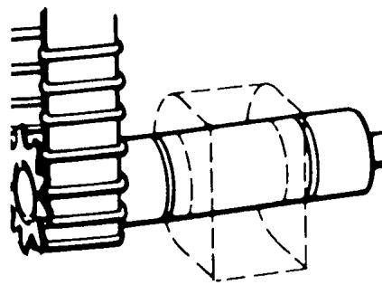
UPPER MAIN SHAFT
MODELS 21, 51, 71, 7, ETC.
REQUIREMENTS
The upper main shaft should run freely during its rotation. There should be no binding and no end play.
ADJUSTMENT
Loosen set screws (1). Pull handwheel away from machine at the same time moving the thrust collar (2) against bearing. Then retighten the set screws.
NOTE On the class 21-A, the thrust collar is located next to the handwheel.
COMMENT
It is possible the thrust collar is running too tightly against bearing. Loosen set screws to relieve pressure.
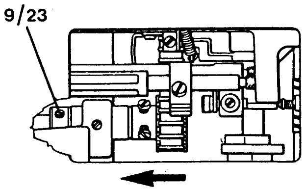
LOWER MAIN SHAFT
REQUIREMENTS
The lower main shaft should run freely during its rotation. There should be no binding and no end play.
ADJUSTMENT
Remove the inspection plate on the underneath of the base plate. Loosen the two (9/23) set screws in the positioning collar. Then press the chain belt in the direction of the arrow and the positioning collar in the opposite direction. Tighten the set screws.
COMMENT
After making this adjustment be sure to check the play of the shuttle gears.
SHUTTLE GAEs
REQUIREMENTS
By taking hold of the outside of the driver and rotating it left to right you should detect a slight amount of free movement.
ADJUSTMENT
The tolerance of the shuttle gears is adjusted by the position of the gear on the lower main shaft (free arm shaft) at the rear of the free arm. Loosen the two (9/2) set screws. Shift the position of the gear to the left to increase the tolerance, to the right to decrease. Tighten the set screw on the flat of the shaft first.
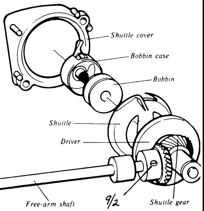
Shuttle transmission
COMMENT
After each correction recheck the tangible play of the driver. Also run the machine to determine if the noise level is within accepted tolerances.
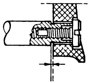
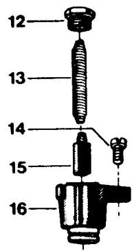
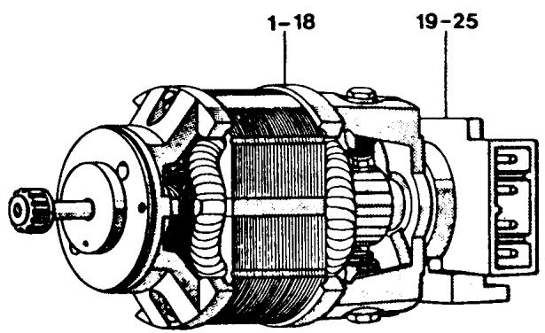
MOTOR
REQUIREMENTS
The motor should run smoothly without a high noise level.
ADJUSTMENT
Check both carbon brushes by removing the brush cap (12). The carbon brushes should be at least 50% the size of new ones. It is recommended that both the carbon brush and spring be replaced. After installing new carbon brushes dress the commutator to seat the brushes.
COMMENT
The motor noise is affected by the load and the belt tension. If the motor deviates from normal check the tension of the cog belt.
When replacing carbon brushes it is important to note the model of the machine. Starting with 6460 the carbon brush holder (16) was redesigned. Once the carbon has worn the holder will not allow the carbon brush spring (13) to ride the commutator. When ordering carbon brushes it is best to use the 40 16 295-01 from 6460 and later models. For earlier models use the carbon brush 41 14 934-01 which will repel from the commutator automatically when the carbon is worn.

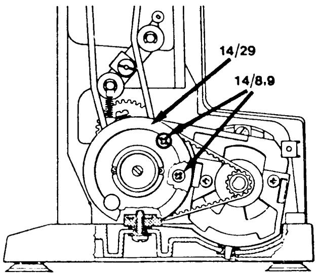
COG BELT
REQUIREMENTS
The belt tension should not be so loose that it permits slipping when the machine is locked and the foot control is depressed. Tighter cog belt tension makes more noise. The belt should not be damaged.
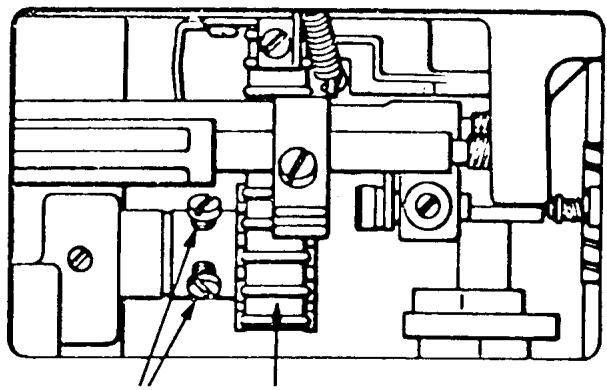
ADJUSTMENT
The screws (14/8, 9) in the reduction gear holder are accessible by means of two holes in the large cog wheel (14/29). If both the screws are loosened, a certain adjustment is possible by moving the frame for the cog wheel one way or the other. Tighten the screws.
COMMENT
On models with electronics a cog belt that is set too tight will affect the speed and power of the needle stop-right positions. The belt should have about 18 of an inch deflection when set correctly.
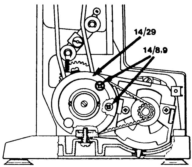
THE V-BELT
REQUIREMENTS
The belt tension should not be too tight or too loose. The slightest amount of slipping is permissible when the hand wheel is held firmly and the foot control depressed.
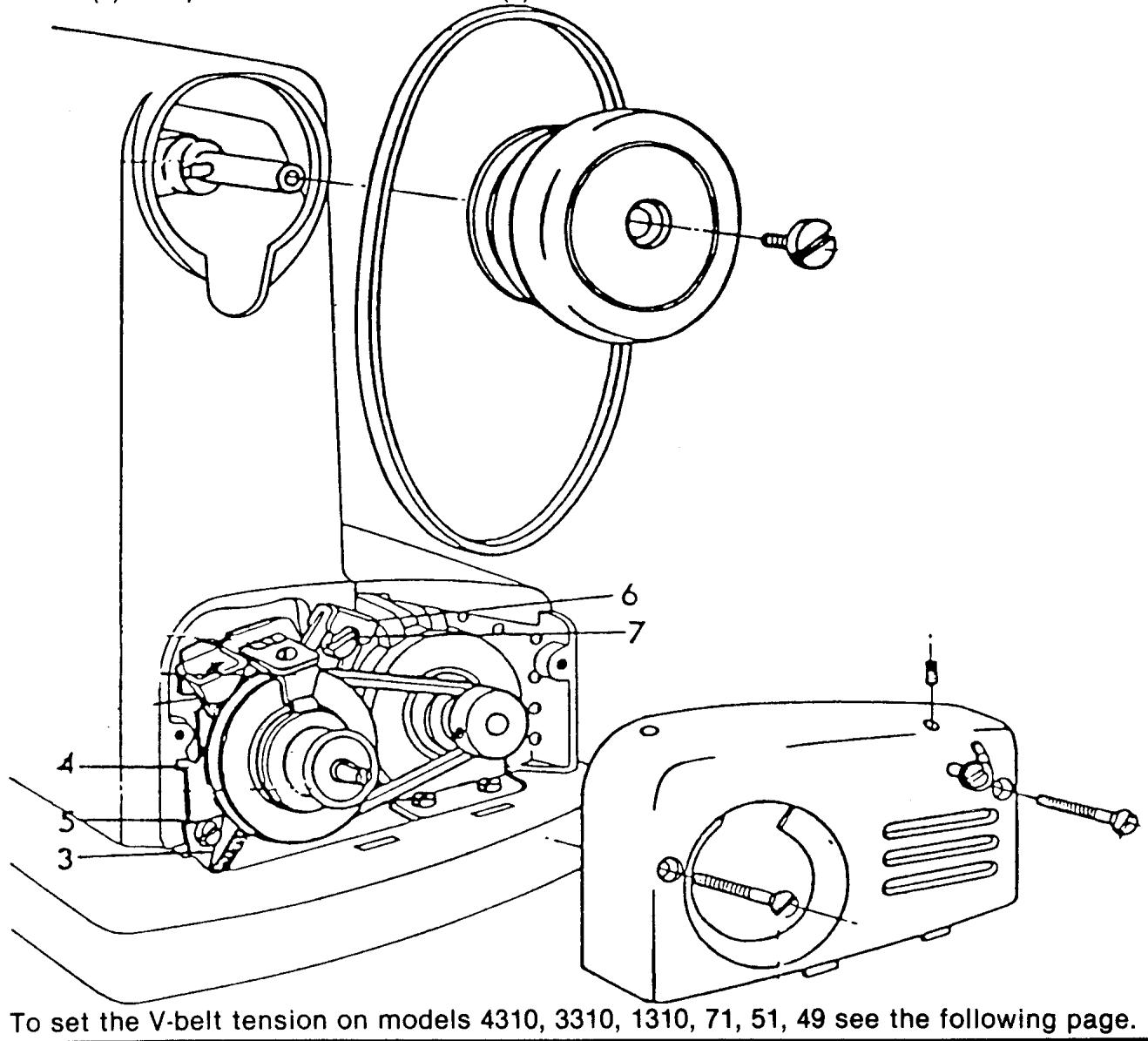
ADJUSTMENT FOR 70 SERIES OR LATER MODELS
The screws (14/8, 9) in the reduction gear holder are accessible by means of two holes in the large cog wheel (14/29). If both the screws are loosened, a certain adjustment is possible by moving the reduction gear up or down.
COMMENT
On the 70 series or later model machines with the dual idler, the tension of the V-belt is set at the same time as the cog belt. Notice the adjustment screws are the same for both.
For models older than the 70 series see the following three pages.
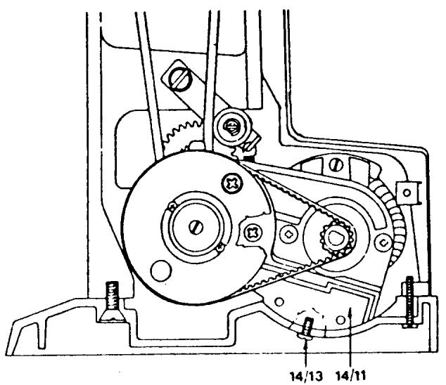
THE V-BELT
MODELS 6460, 6440, 6430, ETC.
REQUIREMENTS
The belt tension should not be too tight or too loose. The slightest amount of slipping is permissible when the hand-wheel is held firmly and the foot control depressed.
ADJUSTMENT
The tension of the belt is decided by the position of the motor bracket (14/11) and also the pressure the belt wheel has on it. Lay the machine on its back and loosen the screw (14/13) approximately a half turn. The tension of the belt can be altered if the screw is pressed downwards.
COMMENT
The tighter the V-belt tension the more piercing power the needle has. But too much tension will cause the machine to bind, run slow and increase the noise level.
To se the V-belt tension on models 10 series (6010),2000,21,19,8 see the following page.
ADJUSTING V-BELT AND LOW GEAR
MODELS 10 SERIES (6010), 2000, 19, 21, 8
REQUIREMENTS
The V-belt tension should be taut enough so no slipping will occur on the pulleys, but not too tight to cause binds.
ADJUSTMENTS
The spring (3) is set so that suitable belt tension is obtained when the guide plate (4) is attached in the vertical position. The position of the guide plate can be adjusted after the screw (5) has been loosened. On later machines the retainer (6) is made with an oval groove for the screw (7). A further possibility of increasing the belt tension is to loosen screw (7) and press down the retainer (6) until the desired belt tension is obtained.
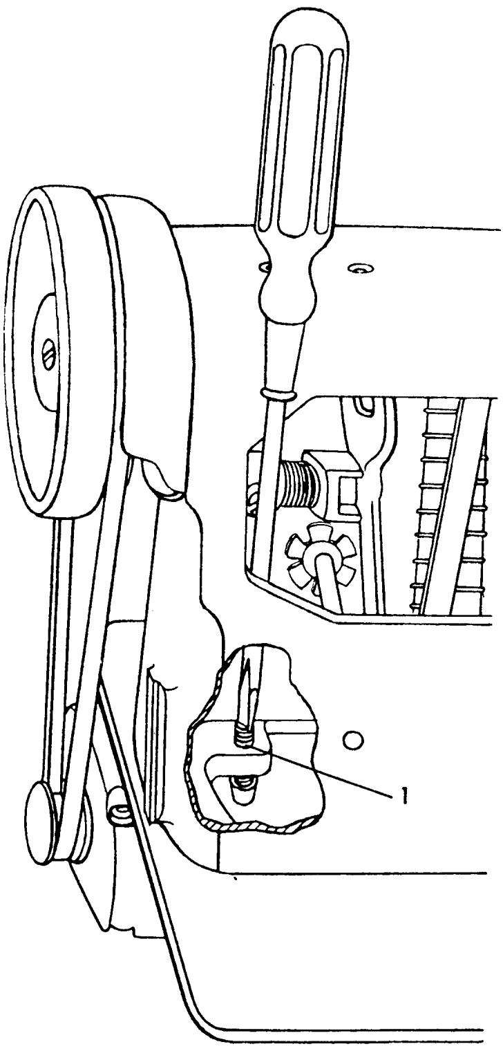
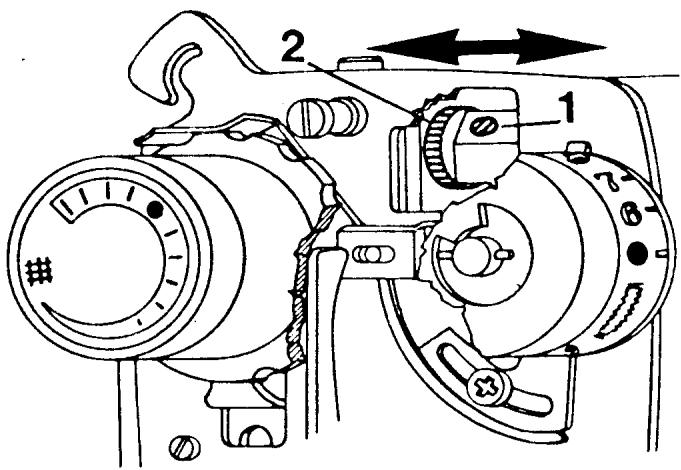
THE BELT TENSION
REQUIREMENTS FOR MODELS
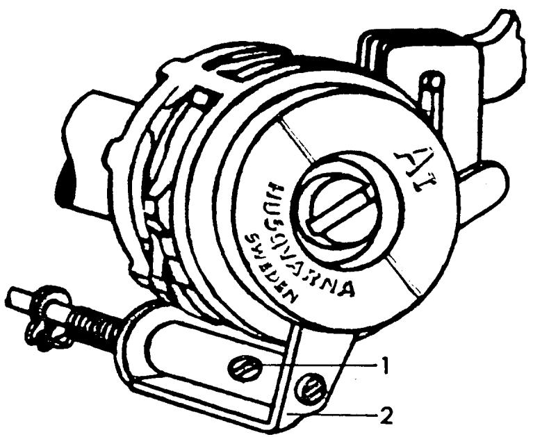
4310, 3310, 1310, 71, 51, 49
When the correct belt tension is set, it should be possible to press together the two belt parts.
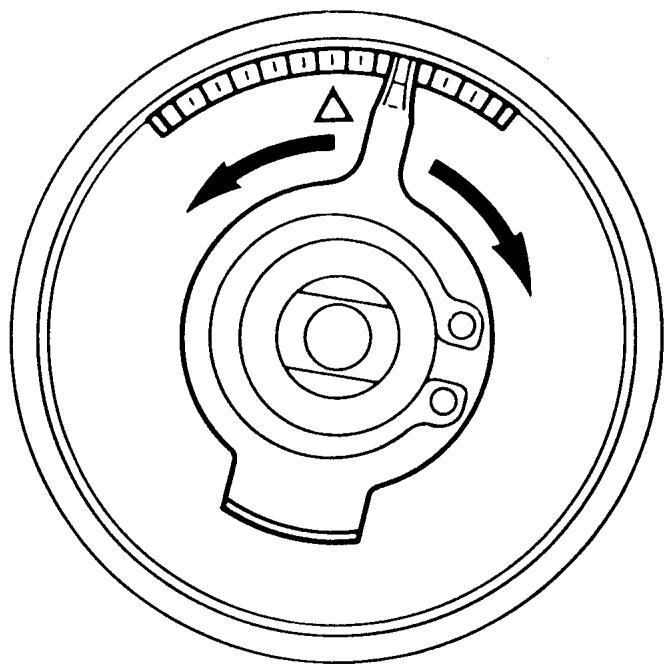
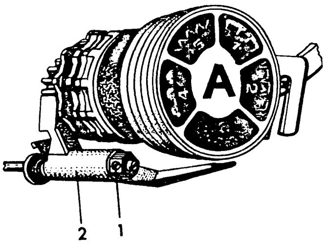
ADJUSTMENT
By turning the adjusting screw (1) clockwise the belt tension will increase. By turning it counterclockwise the tension is reduced.
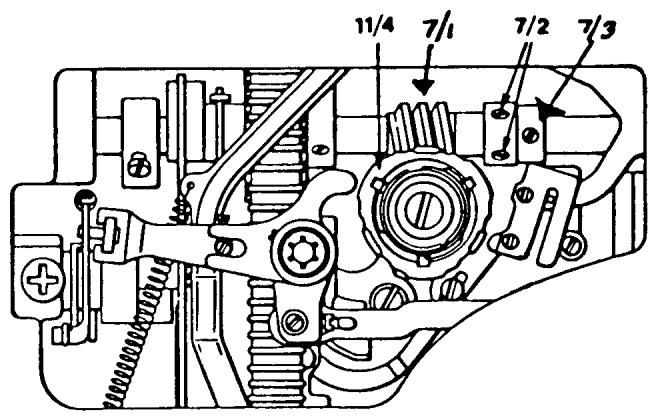
WORM WHEEL TOLERANCE
REQUIREMENTS
There should be little or no clearance between the worm wheel and worm gear on the main shaft.
ADJUSTMENT
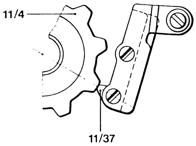
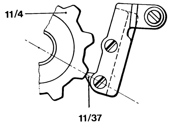
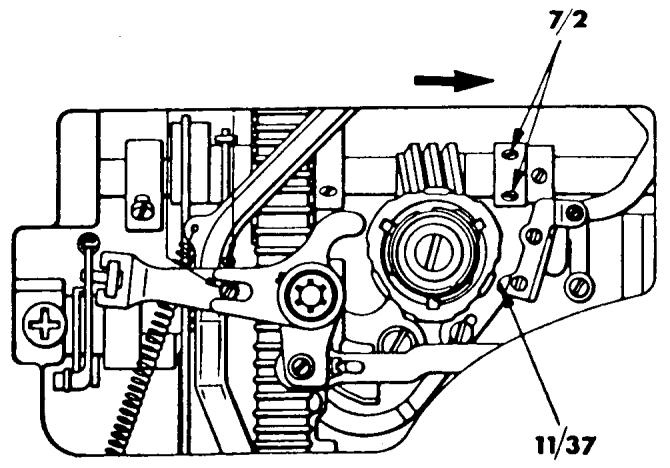
Loosen the two set screws (7/2) on the worm gear. Loosen the set screw (7/3) on the positioning collar. The worm gear (7/1) will now move freely on the main shaft. By positioning the worm gear to the right it will increase the tolerance. To the left will decrease the tolerance. Grasp the fixed cam (11/4) and rotate it to the right, increasing the tolerance between the gears. Then gently rotate the cam counterclockwise to the point where the first resistance of the gears meshing is felt. Secure the set screws (7/2) on the worm gear. Move the positioning collar against the worm gear and tighten the set screw (7/3).
COMMENT
If the tolerance is too tight the machine will run slow. If the tolerance is too loose the machine will have a knock when zigzagging and/or the needle bar will jump swiftly toward the right when on the upstroke.
After making this adjustment the timing of the zigzag movement must be set.

FOOT CONTROL
REQUIREMENTS
The speed should be continuously controllable from a slow speed of 100 ± 200 rev./min. to full speed.
The connection contacts to both the wall socket and the terminal board must not be damaged or deformed.
TO CHECK
Test the foot control on a machine which is known to operate normally. If a satisfactory result is not obtained exchange the faulty foot control. If the cable or plugs are damaged exchange the cord.
COMMENT
The speed controls for models with electronics do not incorporate the standard ohms resistor used on earlier models. The new control has a potentiometer which is a switching mechanism that operates on low voltage. The actual speed control is the printed circuit board. This type of control cannot be used in place of the conventional controllers now employing ohms resistors or vice versa.
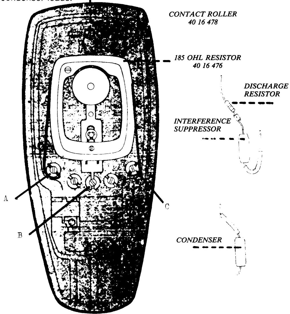
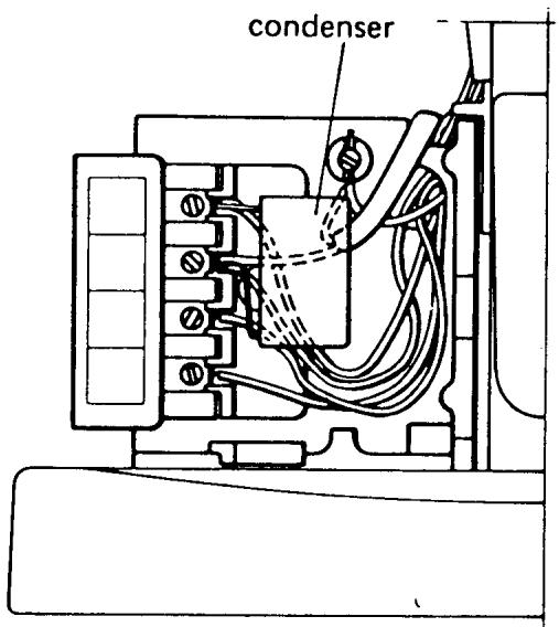
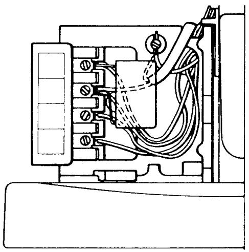
TERMINAL BOARD
REQUIREMENTS
All connections and cables must be securely fixed to their corresponding binding post.
COMMENT
The terminal board is color coded for correct wiring.
If there is interference in radio or television reception from the machine, exchange the interference suppressor (condenser).
MOTOR
COMMENT
The functioning of the motor can be checked without dismounting the printed circuit board. First check the carbon brushes for wear and to see that a carbon is not sticking in the brush holder.
If the motor still does not function, use a spare circuit board and connect it to the connections on the terminal board. Test the machine to see if it functions properly.
If the motor runs normally the fault was in the printed circuit board. If it still does not function correctly the fault is in the motor which must be replaced.
NOTE The procedure to remove the circuit board and for installation of a new one are on the following page.
PRINTED CIRCUIT BOARD
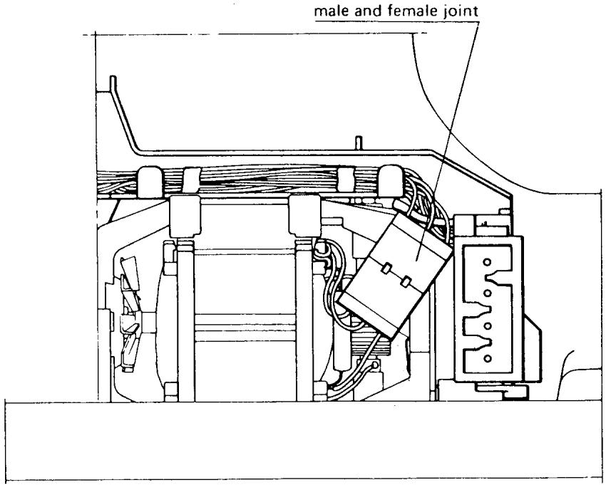
DRIVING OF THE MOTOR
If the machine operates when the motor is connected with a spare part circuit board but not when the mounted circuit board is connected, remove the faulty circuit board and send it in for repair.
COMMENT
Note that the brush holder and open wiring of the motor and the rear of the printed circuit are electrified as soon as the wall plug is connected. The on/off switch does not de-electrify the printed circuit. Make it a habit of removing the plug from the wall socket as soon as the belt guard is removed and only reconnect when it is absolutely necessary.
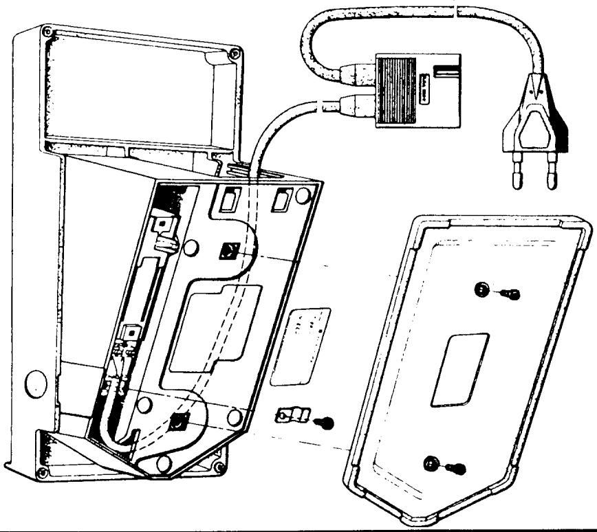
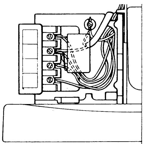
REMOVAL
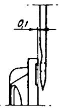
Loosen the 5 screws in the board which hold red, black, white, yellow and blue wires. The lighting cable and condenser (0.1 F) should remain connected. Remove the 2 screws (the cross-grooved screws) which hold the printed circuit board and separate the conductor joint at the motor. Remove the covering from the wires and push the wires through the hole in the terminal board.
PRINTED CIRCUIT BOARD CONTINUED
ASSEMBLY
Assembly should be carried out in a corresponding way, i.e., affix the covering of the wires and push the 5 wires back through the hole in the terminal board. Note that the wires must be connected to their respective colors. Replace the printed circuit board and press the conductor joint in, making sure each corresponding colored wire matches.
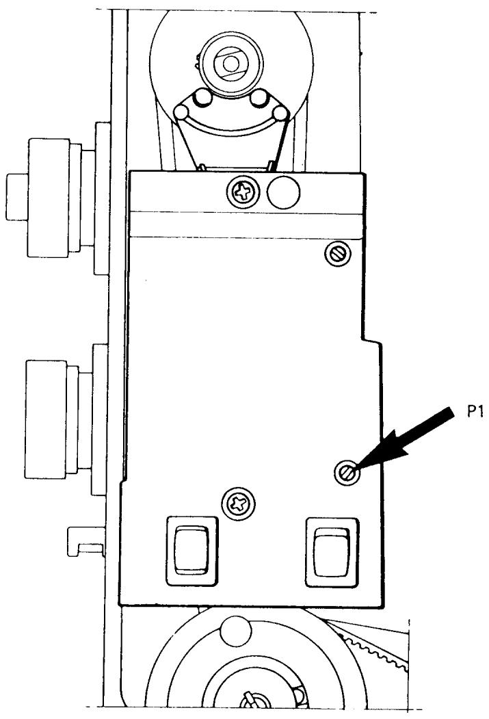
THE LOWEST SPEED OF THE MOTOR
REQUIREMENTS
The machine should manage a lowest speed of 100 ± 209 rev./min.
DETERMINATION
Remove the wall plug. Set the thread take-up lever at the lowest position and remove the handwheel. Remove the belt guard. Set the stop-right pushbutton at the neutral position. Connect the machine but remember that the brush holder and open wires of the motor and the rear of the printed circuit are electrified and unprotected, even if the main switch is off. Turn on the main switch. Start the machine and depress the foot control so that the machine runs at the lowest possible speed.
Count the number of revolutions during 15 seconds (i.e., 25-30 revolutions). A piece of paper placed under the presser foot will indicate the number of needle holes.
ADJUSTMENT
The number of revolutions can be adjusted by means of the lower potentiometer (P1). Turn the potentiometer counterclockwise for a higher speed, clockwise for a lower speed.
COMMENT
There are magnetic bars (reed switches) on the upper part of the printed circuit board which sense the position of the handwheel. These must not come into contact with metal objects. For this reason always set the thread take-up lever at the lowest possible position when removing or replacing the handwheel, so that the indication plate of the handwheel cannot come into contact with the reed switches.
TAKE HOME TURNING SPEED
EXPLANATION
The homing speed is a measurement of the capacity of the electronics to turn the upper main shaft after release of the foot control. It should be sufficient to drive the machine to the selected stop-right position.
DETERMINATION
Set the stop-right pushbutton to the up or down position. Handwheel must be dismounted. Start the machine and depress the foot control so that the machine runs at the lowest possible speed.
Release the foot control. The speed must not increase during the first second but a slight decrease is acceptable.
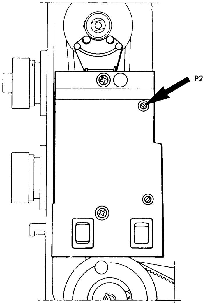
ADJUSTMENT
The homing speed is set by means of the upper potentiometer (P2). A higher speed is obtained by turning the potentiometer counterclockwise, a lower speed by turning it clockwise.
COMMENT
The homing speed should be sufficient to drive the machine to the selected stop-right position. However, if the speed is too high, the machine will make extra stitches after release of the foot control.
SETTING THE UPPER STOP-RIGHT POSITION OF THE NEEDLE
REQUIREMENTS
When the needle stops at the upper stop-right position the distance between the stitch plate and the needle tip should be between 14 and 9mm . (The sole of standard presser foot is 14mm .)
ADJUSTMENT
With the thread take-up lever in its lowest position mount the handwheel with the indication plate at the top. Engage the stop-right to the up position. Press the foot control and release it. Measure the distance between the stitch plate and needle tip as per requirement. If correction is required, the upper stop-right position is set by moving the plate in the handwheel to the right to raise the needle, to the left to lower the needle.
COMMENT
This adjustment ensures that all the thread has cleared the shuttle system and the sewing project can easily be removed.
INTRODUCTION FOR SERVICE ADJUSTMENTS
This Technical Service Manual contains all the adjustment procedures that should be checked when doing a complete service on a Viking Husqvarna sewing machine.
These procedures should be followed in sequence, because certain adjustments will influence others.
There are some requirements that do not appear on earlier model machines. If this is so, skip the requirement and move on to the next procedure.
Before beginning the following checks, install a new size 90 needle. It is important the machine is adjusted as close to the requirements as possible. Use the gauges where applicable and use good tools on the machines.
THE RAISE OF THE CAM FOLLOWER
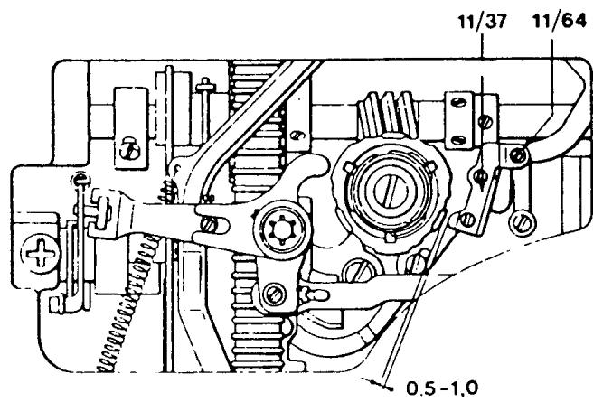
REQUIREMENTS
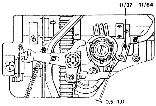
Set the pattern selector knob for zigzag and the stitch length knob and width knob at 4. Turn the handwheel until the cam follower (11/37) reaches the highest point on a cam lobe. Then turn the stitch width knob to zero. In this position the cam follower should be raised 0.5 - 1.0 mm over the cam lobe.
ADJUSTMENT
Turn the eccentric screw (11/64) until the required gap is obtained. The adjustment screw is friction loaded and may be turned in either direction.
COMMENT
This adjustment ensures that the stitch width cam follower will not be riding a cam lobe when the machine is set for straight sewing. Thus, no zigzag on a straight stitch.
NOTE On older style machines without the adjustment screw (11/64), taking the zigzag out of the straight stitch is discussed later in this manual.
ALIGNMENT OF THE STITCH WIDTH CAM FOLLOWER
REQUIREMENT
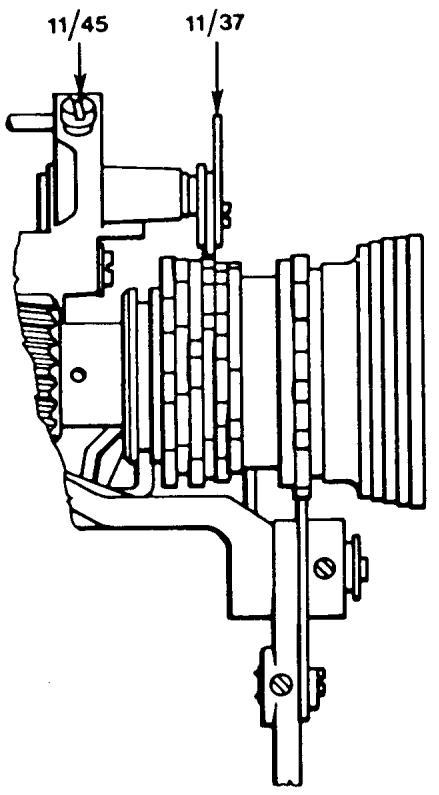
The cam follower (11/37) should meet the programmer or fixed cam in the middle of a cam disc.
ADJUSTMENT
If adjustment is necessary, lower the lamp assembly, and insert a long screwdriver through the oval-shaped opening in the thread tension mounting plate. Loosen the set screw (11/45). Manually position the cam follower in or out until the correct alignment is obtained. Secure the set screw.
COMMENT
If this adjustment is off then the cam follower will ride two lobes.
NOTE On the following page is the procedure for making this adjustment on models 4310, 4010.
CENTERING THE STITCH WIDTH CAM FOLLOWER MODELS 4310, 4010.
REQUIREMENTS
The cam follower must ride on the middle of a cam disc.
ADJUSTMENT
Set the stitch selector at the zigzag symbol and the stitch width knob at position 4. Turn the handwheel until the cam follower rides a lobe on the zigzag cam. Loosen screw 1 and adjust the cam guide. Tighten the set screw.
NOTE On the following page is the procedure for making this adjustment on models 51, 21.
CENTERING THE STITCH WIDTH CAM FOLLOWER MODELS 51, 21
REQUIREMENTS
The stitch width cam follower must ride on the middle of a cam disc.
ADJUSTMENT
Set the pattern selector to 5 and the stitch width to 4. Turn the handwheel until the cam follower comes to the top of a cam lobe. Loosen set screw (1), then cam guide (2) and the cam can be adjusted to the correct position. Tighten the set screw.
RETRACTION OF THE ZIGZAG CAM FOLLOWER
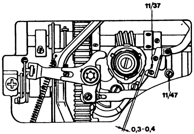
REQUIREMENTS
Set the stitch selector at zigzag, the stitch length and width knobs at 4. Turn the handwheel until the cam follower (11/37) reaches a cam lobe. Place the indicator point of the stitch selector in front of the index point. In this position the cam follower should lift 0.3 - 0.4 ~mm from the cam lobe.
ADJUSTMENT
Turn the eccentric screw (11/47) until the required lift is reached. The screw is friction loaded. It can be turned in either direction, but at no time should it be turned more than 180 degrees left or right.
COMMENT
If the zigzag cam follower does not raise the required amount it could come in contact with a cam lobe causing the programmer to disengage. If there is too much clearance there will be a bind in the draw rod to the needle bar frame.
TIMING THE ZIGZAG MOVEMENT
REQUIREMENTS
The side movement of the needle when sewing zigzag should be completed before the tip of the needle reaches the level of the stitch plate. Rotate the handwheel and set the needle bar in its lowest possible position. The tip of the cam follower (11/37) should be directly centered on the cam lobe.
ADJUSTMENT
Rotate the handwheel and loosen the set screws (7/2) on the worm gear. Set the pattern selector to the white dot taking pressure off the cam. Rotate the handwheel and place the needle bar in its lowest position. Rotate the worm gear on the main shaft, revolving the fixed cam so the tip of the cam follower is centered on a cam lobe (11/37). Ensure the worm gear is firmly against the positioning collar on the main shaft. Secure the first set screw.
If the set screw is not available, grasp the programmer and load it by firmly turning clockwise. At the same time rotate the handwheel forward in the running direction until a set screw is available. Recheck the requirement.
COMMENT
If this adjustment is not correct, crooked feeding and needle breakage will occur.
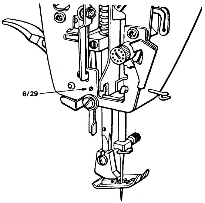
NEEDLE BAR FRAME STOP
REQUIREMENTS
The needle bar frame stop must not prevent the needle from reaching the full zigzag, but should stop the needle from going outside the needle hole in the stitch plate.
CHECK I
Set the pattern selector for zigzag and the stitch width knob at 4. Turn the handwheel until the needle tip is level with the stitch plate and in the left-hand position. Test by pushing gently against the needle bar that there is a little play between the frame and the stop. It should not be possible to push it so far that the needle tip goes outside the needle hole in the stitch plate. But it is acceptable if the side of the needle rubs the stitch plate.
CHECK II
Remove any programmer in the machine and set all control dials to the blue symbol. Rotate the handwheel and check that the tip of the needle just enters the stitch plate slot on the right. It is acceptable if the side of the needle touches the stitch plate.
ADJUSTMENT
The position of the stop is adjustable with the screw (6/29).
COMMENT
Check II prevents needle breakage if the customer fails to install a programmer and has the control dials set to the blue symbol.
NOTE To make this adjustment on 6010 and earlier models see the next page.
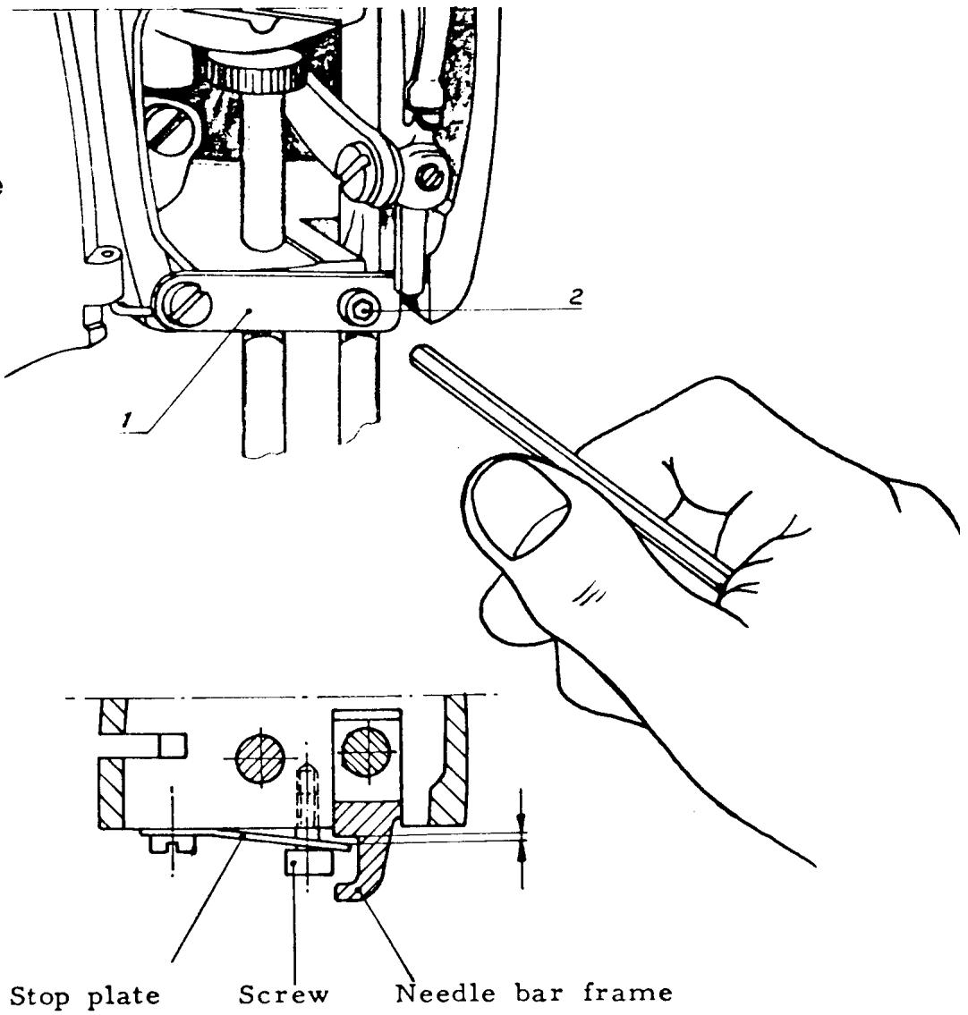
NEEDLE BAR FRAME STOP
MODELS 6010 AND EARLIER
REQUIREMENTS
The needle bar frame stop (1) must not prevent the needle from reaching the full zigzag, but should stop the needle from going outside the needle hole in the stitch plate.
CHECK
Set the machine for maximum zigzag. Turn the handwheel until the needle tip is level with the stitch plate and in the left hand position. Test by pushing gently against the needle bar that there is a little play between the frame and needle bar stop (1). It should not be possible to push it so far that the needle tip goes outside the needle plate hole. But it is acceptable if the side of the needle rubs the stitch plate.
ADJUSTMENT
The position of the stop is adjusted with the screw (2).
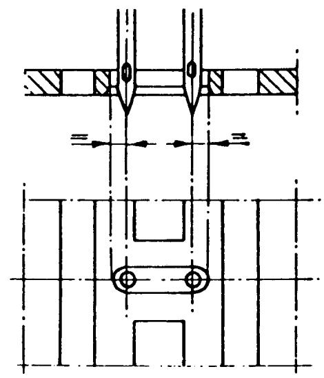
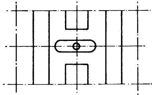
CENTERING THE MAXIMUM ZIGZAG WIDTH
REQUIREMENTS
The zigzag position of the needle should be symmetrically positioned in the needle hole.
ADJUSTMENT
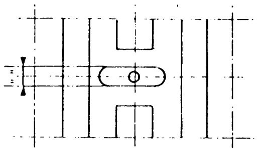
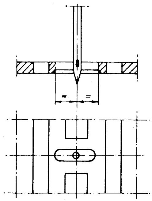
Set the stitch width knob at 4. Turn the handwheel until the needle is well into the stitch plate on the right side. Observe the distance between the edge of the stitch plate slot and the side of the needle. Rotate the handwheel and put the needle down on the left side. The distance should be the same as on the right side. The position of the needle can be adjusted two ways:
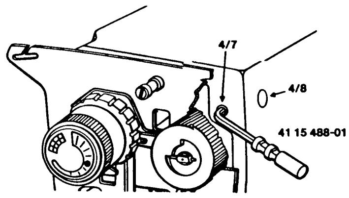
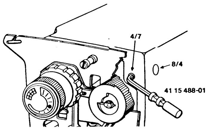
(a) Remove the stitch pattern scale in the direction of the arrows. Rotate the handwheel and put the needle down on the side that has the largest clearance. Place the Adam key into the set screw (4/7) and lift up to loosen the screw. Remove the tool. Place the tip of the screwdriver into the slotted eccentric (4/8). By turning the eccentric left or right, move the needle bar over one-half the required distance observed. Rotate the handwheel and check for equal clearance.
CENTER THE MAXIMUM ZIGZAG WIDTH CONTINUED
COMMENT
If the eccentric screw (4/8) is shifted axially, this will affect the needle position front to rear. If the required needle position cannot be obtained, turn the screw (4/8) to a middle position and tighten the set screw (4/7) and adjust the position as follows:
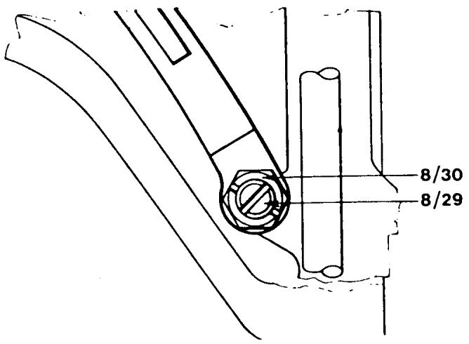
(b) Put the box spanner 41 11 907-01 on the nut (8/30) and loosen the screw (8/29) in the center of the nut. Turn the box spanner until the required position is obtained. Tighten the screw (8/29).
NOTE To make this adjustment on the 30 series turn to the following page.
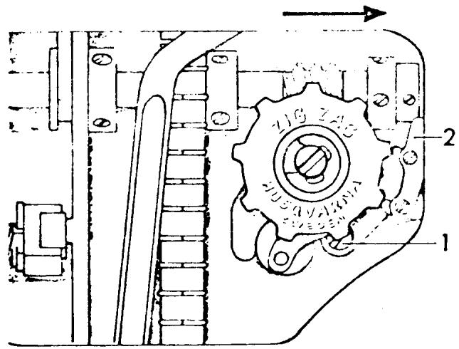
CENTERING THE MAXIMUM ZIGZAG WIDTH 30 SERIES
REQUIREMENTS
The zigzag position of the needle should be symmetrically positioned in the needle hole.
ADJUSTMENT
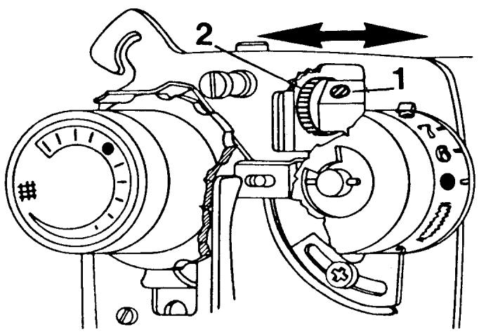
Set the stitch width knob at 4. Turn the handwheel until the needle is well into the stitch plate on the right side. Observe the distance between the edge of the stitch
plate slot and the side of the needle. Rotate the handwheel and put the needle down on the left side. The distance should be the same as on the right side. To make a correction loosen the set screw (1). The shaft on the grooved wheel (2) is eccentric and when turned the position of the needle is altered. Turn the grooved wheel until the requirement is met. Tighten the set screw (1).
NOTE I If the grooved wheel is moved axially (in the direction of the arrows) the needle position front to rear will be affected.
NOTE II To make this adjustment on model 6020 and earlier see the next page.
CENTERING THE MAXIMUM ZIGZAG WIDTH
20 SERIES AND EARLIER MODELS
REQUIREMENTS
The zigzag position of the needle should be symmetrically positioned in the needle hole.
ADJUSTMENT
Set the pattern selector at the zigzag symbol and the stitch width knob at 4. Turn the handwheel until the needle is well into the stitch plate on the right side. Observe the distance between the edge of the stitch plate slot and the side of the needle. Rotate the handwheel and put the needle down on the left side. The distance should be the same as on the right side. To make a correction, loosen screw (1). Adjust the position of the needle by means of eccentric (2) until the needle movement (zigzag) is centered in the stitch plate. Tighten screw 1.
NOTE Before tightening screw (1) make sure the eccentric (2) is flush to the drawrod.
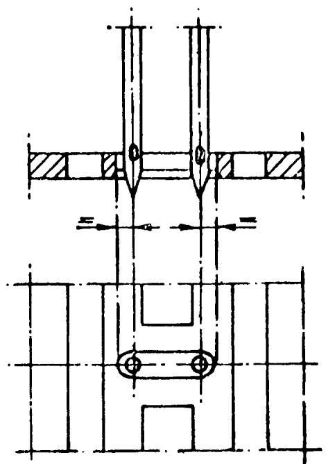
Fig. 6
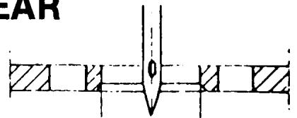
NEEDLE POSITION FRONT TO REAR
REQUIREMENTS
The needle must be centered front to rear in relation to the needle hole of the stitch plate.
ADJUSTMENT
Set the stitch width knob at 0. Turn the handwheel until the needle is in its lowest position. Remove the stitch pattern scale. Use the Adam key 41 15 844-01 and insert into the stop screw (4/7). Lift up to loosen. Now the shaft (8/4) which supports the needle bar frame can be shifted back and forth (axially) until the required needle position is obtained. Tighten the stop screw (4/7).
COMMENT I
The shaft (8/4) is eccentric and if turned will affect the zigzag position in the needle plate.
COMMENT II
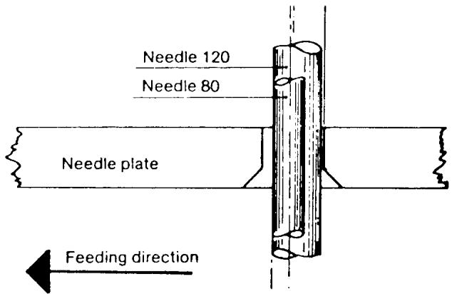
The distance between the center of the needle and the flat part of the needle base varies with the thickness of the needle. In order that needle (size 120) can move freely from the front edge of the needle hole, set the needle bar in such a way that needle (size 90) is in the middle of the needle hole. Needle (size 80) will then be slightly behind the center of the needle hole. Always set this adjustment looking directly from the end of the machine.
NOTE To make this adjustment on 30 series machines see the following page.
NEEDLE POSITION FRONT TO REAR
30 SERIES
REQUIREMENTS
The needle must be centered front to rear in relation to the needle hole of the stitch plate.
ADJUSTMENT
Set the stitch width knob at 0. Turn the handwheel until the needle is in its lowest position. Loosen set screw (1). Now the grooved eccentric wheel (2) can be pivoted in the direction of the arrows. Center the needle in the stitch plate hole. Tighten the set screw.
NOTE I
If the grooved eccentric wheel is turned the zigzag position in the stitch plate will be affected.
NOTE II
Use a size 90 needle when setting this adjustment.
NOTE III
To make this adjustment on the 20 series or earlier models refer to the next page.
NEEDLE POSITION FRONT TO REAR
20 SERIES AND EARLIER MODELS
REQUIREMENT
The needle must be centered front to rear in relation to the needle hole of the stitch plate.
ADJUSTMENT
Set the stitch width control at 0 so the machine is in center needle position. Turn the handwheel until the needle is in its lowest position. Loosen screw (1) and move the needle bar frame in the direction of the arrow until the needle is centered in the stitch plate hole.
NOTE Use a size 90 needle when setting this adjustment.
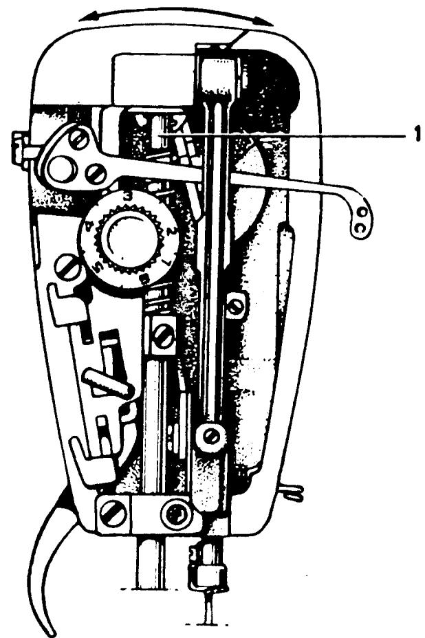
Fig. 1
CHECKING FOR ZIGZAG ON A STRAIGHT STITCH
NOTE
This is applicable to all machines that have automatic buttonholes but do not have the adjustment screw (11/64) on the stitch width cam follower.
REQUIREMENTS
When the machine is set for straight sewing the stitch width cam follower should not ride a cam lobe.
ADJUSTMENT
Set all controls for straight sewing. Run the machine at a moderate speed and check that the stitch width cam follower has no movement. If movement is detected, turn the vertical adjustment screw (1) clockwise in one-quarter increments until the movement ceases.
COMMENT
If the adjustment screw (1) is turned too much clockwise the cutting space of the buttonhole will be too wide. If it is turned too much counterclockwise the cutting space will be nonexistent.
LEFT NEEDLE POSITION
REQUIREMENTS
The left-hand needle position shall be in accordance with the left-hand zigzag position.
CHECK
Lower the feed teeth. Set the stitch selector on the zigzag symbol and the stitch width knob at 4. Place a piece of masking tape under the presser foot. Carefully pierce the tape with the needle in the left-hand position; turn the handwheel backwards so the needle is above the tape. Set the stitch selector at the symbol for left-hand position, then set the stitch width dial at 0. Guide the needle towards the tape. The needle must go into the same hole as before.
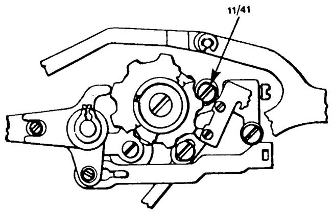
ADJUSTMENT
Turn the upper eccentric screw (11/41) to meet the requirements above.
COMMENT
When turning the eccentric screw (11/41) always turn it clockwise. Always set this adjustment when the needle is moving towards the end of the open arm.
NOTE It is very important that the zig-zag is centered in the stitch plate before making this adjustment.
CENTER NEEDLE POSITION
REQUIREMENT
The needle should be in the center of the zigzag.
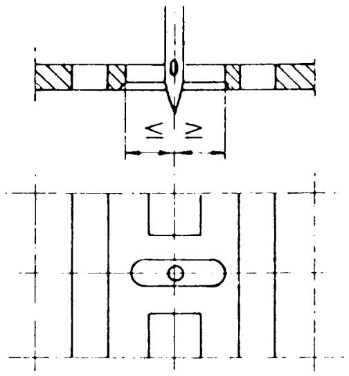
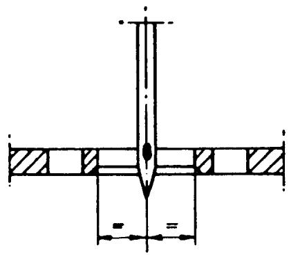
CHECK
Lower the feed teeth. Set the stitch selector at the zigzag symbol and the stitch width knob at 4. Place a piece of masking tape under the presser foot and pierce it on both the right and left sides of the zigzag. Now set the stitch width knob at 0. Turn the handwheel until the needle pierces the tape. This hole should be centered between the two zigzag holes.
ADJUSTMENT
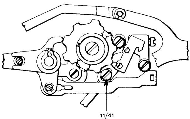
Turn the lower eccentric screw (11/41) clockwise until the needle reaches the above requirement.
COMMENT
This adjustment eccentric, like that of the left-hand eccentric, must always be turned clockwise, and must always be set with the needle traveling toward the end of the open arm.
NOTE I It is very important that the zigzag is centered in the stitch plate before making this adjustment.
NOTE II For making this adjustment on machines without automatic units, i.e., models 21, 19, 51, 49, 1020, 1030, etc., refer to the following page.
CENTER NEEDLE POSITION
MODELS WITHOUT AUTOMATIC UNITS
REQUIREMENT
The needle should be in the center of the stitch plate hole.
CHECK
Set the knob for the needle position on the middle symbol. (For machines with pattern selectors set on 5.) Turn the stitch width knob to 0. Turn the hand-wheel until the needle tip is below the stitch plate. The needle should be in the center of the stitch plate.
ADJUSTMENT
Loosen screw (1) and press the guide (2) in the direction of the arrow so that the needle comes between the center and left needle positions. This will release pressure on the guide (2). Now by adjusting the guide bring the needle to its center needle position. Tighten screw (1).
C1. 49
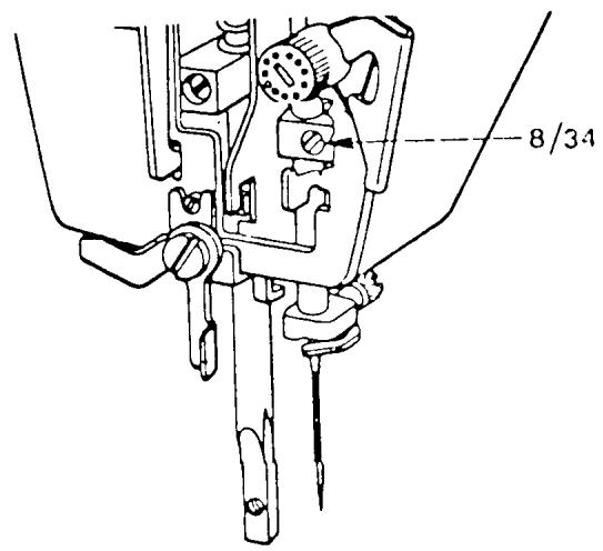
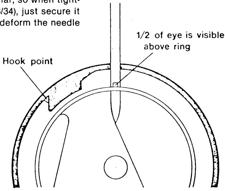
NEEDLE BAR HEIGHT
REQUIREMENTS
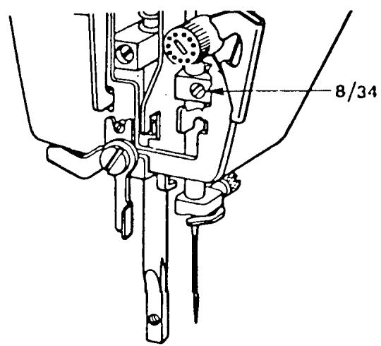
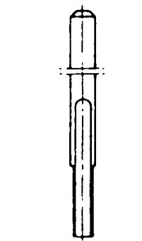
When the tip of the hook passes the center of the needle, the gap between the tip and the upper edge of the needle eye should be 1.5mm . Since this is a difficult measurement to determine, another method is suggested. Place the shuttle in the driver. Put the needle in its lowest position. By looking straight on, determine that one-half of the needle eye is visible above the outer guard ring of the shuttle (hook).
ADJUSTMENT
Loosen screw (8/34) and move the needle bar up or down to the requirement. Moderately tighten the set screw.
COMMENT I
When measuring the position of the needle eye be sure to hold the hook downward and counterclockwise. This is the position it is in when the machine is running.
COMMENT II
The needle bar is tubular, so when tightening the set screw (8/34), just secure it moderately, so not to deform the needle bar.
NEEDLE BAR ALIGNMENT
REQUIREMENT
The needle must be parallel to the stitch plate hole and shuttle (hook).
ADJUSTMENT
Install a 4.0/90 double needle. Rotate the handwheel and put the needles in the their lowest position. Look directly from the end of the open arm to see if the needles are parallel to the stitch plate. To adjust loosen set screw (8/34) and without moving the needle bar up or down twist it until they are parallel. Tighten set screw.
COMMENT
Remember that the needle bar is tubular. If the set screw is tightened too much, the needle bar may become deformed and the machine will run in a bind.
NEEDLE TO HOOK CLEARANCE
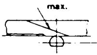
REQUIREMENTS
Remove the shuttle cover.
Set the stitch selector for straight sewing.
Insert the needle gauge No. 41 15 800-02 into the needle bar. Lay the machine on its back.
When the tip of the hook is in front of the center of the needle press the hook against the driver. The gap between the needle and the hook should not exceed the maximum 0.4 mm.
Setting Needle Distance
View B. Scale 2!1
COMMENTS
The hook must have some axial movement so the thread loop is able to go between the hook and drive. This makes contact between the needle and hook possible. This contact can be heard if the machine is running without thread. The hook is designed with a needle support which meets the contact. This contact damages neither the hook or the needle as long as the needle system 705 H is used. This system of needles has a scarf on the back side.
ADJUSTMENT
Settings according to requirements.
Turn the handwheel until the needle is in its highest position. The slot in the driver is now in the middle, underneath the feed dog. Undo the three screws which hold the hook cover — remove the hook cover and the hook. Then undo the three screws (9/11) in the driver (9/10), and remove it. The position of the driver is
NEEDLE TO HOOK CLEARANCE
continued
adjusted by removing or adding one or several shims. When putting the driver back on the machine, note the position of the slot and install in the same position as when removed.
NOTE I The shuttle cover clearance must be checked after this adjustment.
NOTE II if sufficient adjustment is not possible by removing all the shims, see the comment and procedures below.
NOTE III For making this adjustment on models 49, 51, 71, etc., see the next 2 pages.
COMMENT
If all shims have been removed and there is still no clearance between the needle and hook, first make sure the needle (90) is centered front to back in the needle plate. If set correct and still no clearance, follow procedures for moving shuttle gear and bushing.
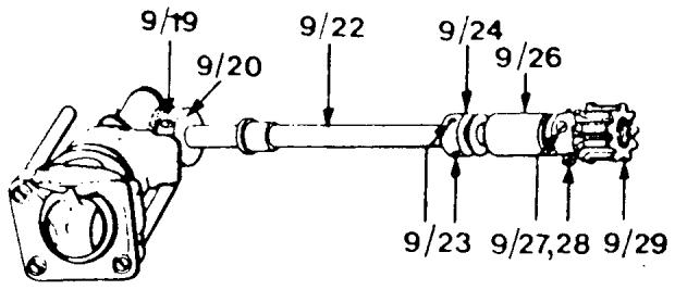
PROCEDURES
Remove the driver (9/10) and the dust guard (9/9). Loosen the two screws (9/19) in the cog wheel. Move the cog wheel to the right 1 mm and moderately secure one of the screws. Loosen the screw (9/37) for the bushing (9/4) on the shuttle shaft. The screw can be reached through the hole in the casting through the base plate. With this screw loose, shift the gear and bushing to gain the required clearance. Tighten screw (9/37).
NOTE I Move the gear and bushing only as much as needed. If they are moved too much the machine could run noisy.
NOTE II Set the shuttle gear tolerance as we described earlier in this manual.
NEEDLE TO HOOK CLEARANCE
MODELS: 49,51,71,6320,6310,4310,1310,3310,3320,etc.
REQUIREMENTS
Remove the shuttle cover. Set the stitch selector for straight sewing. Insert the setting gauge No. 41 15 800-02 into the needle bar. Lay the machine on its back. When the tip of the hook is in front of the center of the gauge as in Fig. 25, press the hook against the driver. The gap between the needle and the hook should be as small as possible.
Max. 0.4mm. See Fig. 26.
ADJUSTMENT
Loosen screw (1). Remove or insert shims to meet requirement.
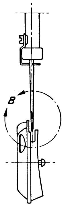
Fig. 25
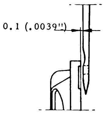
Fig. 26
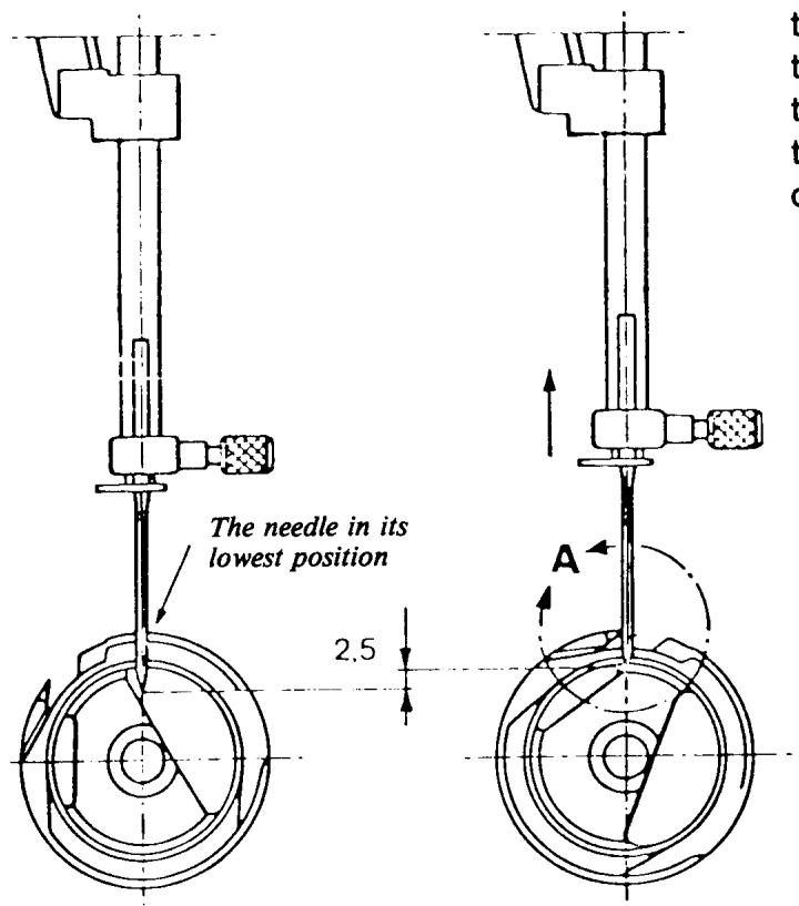
SHUTTLE TIMING
REQUIREMENTS
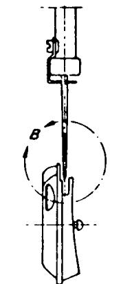
Set the stitch selector for straight sewing. As the needle is moving upwards the tip of the hook should pass the center of the needle when the needle is 2.5mm above its lower turning position (the distance for forming the loop).
ADJUSTMENT
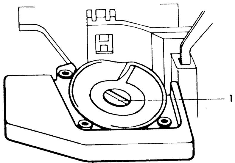
Remove the shuttle cover. Remove the inspection plate cover under the base plate. There are three screws on the pulley, one untreated (9/27) and two black ones (9/28). Remove the untreated screw and one of the black screws and change their places, still leaving them loose. Then loosen the other black screw enough so that the lower shaft still turns when the handwheel is rotated.
Turn the handwheel until the needle is in it lowest position. Place the setting gauge 41 11 752 on the needle bar. Push the gauge up until the spring-loaded stud just touches the needle bar frame and tighten the screw. Turn the handwheel in the same direction as the machine runs until the spring-loaded stud rests against its stop in the gauge according to the right-hand figure. The needle has now moved up 2.5 mm from
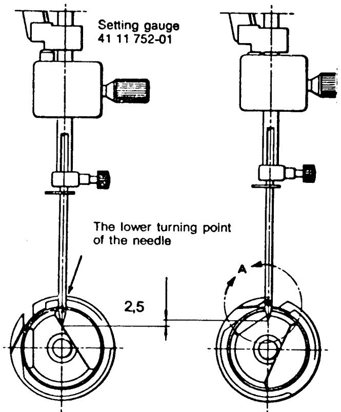
NOTE
The tip of the hook at the centre of the needle
9/27 9/28 9/29
continued
the turning position (the distance for forming the loop). Hold the handwheel fast and turn the hook and the driver so that the tip of the hook comes in front of the center of the needle. Secure one of the black screws. Turn the handwheel in the opposite direction until the needle returns to its lower turning position. Hold the hook back with one finger, so that it is pushed downwards and backwards, and turn the handwheel in the same direction as the machine runs. When the stud on the setting gauge is once again resting against its stop, the tip of the hook should be in the center of the needle. Tighten the remaining black screw, then the silver untreated screw.
NOTE I
Before tightening the first black screw press the chain belt pulley to the left removing any possible play in the lower main shaft.
NOTE II
To make this adjustment on earlier models see the next page.
SHUTTLE TIMING
FLAT-BED ALL MODELS
Set the machines, classes 51 and 49 for straight stitching in the middle needle position. Loosen the three screws on the pulley 1 Fig. 22. Turn the handwheel until the needle reaches its lowest turning position. Place the clamp 41 11 752 on the needle bar as shown in Fig. 20. Push the clamp upwards until the spring loaded stud touches the needle bar frame. Secure the clamp on the needle bar. Turn the handwheel until the spring-loaded stud rests against its stop in the gauge as shown in Fig. 21. By turning the handwheel in the same direction the machine runs the needle has raised 2.5mm from its original position. During this movement the thread loop to be caught by the hook is formed. There is a certain play between the hook and the driver and at this setting it is necessary to press the hook inwards/downwards toward the driver so that it rests against the
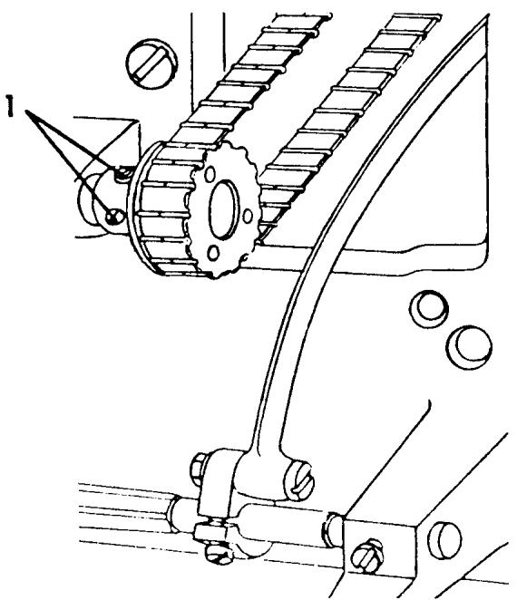
Fig. 22
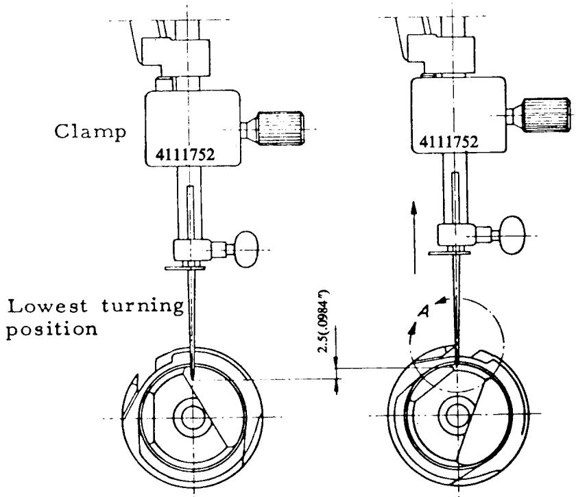
Fig. 20
Fig. 21
continued
lower edge of the driver. At the same time, turn the hook to the left until the catch on the back of the hook rests against the left side of the slot in the driver.
Turn the hook and driver until the point of the hook is in line with the center of the needle. See Fig. 21.
Tighten one of the black screws 1 Fig. 22 on the lower pulley. Remove the clamp.
Re-check the setting. The remaining untightened screws, the black one and the silver one should change places, then tighten them. The silver screw is a head screw with a cone point, which makes a cavity (mark) in the shaft. If the two screws do not change places there is always the risk that the point will slip back to its old position. Old machines are not supplied with such a cone point screw.
COMMENT:
After making this adjustment the feed height eccentric will require adjustment. See page 107.
SHUTTLE COVER CLEARANCE
REQUIREMENTS
The gap between the shuttle cover and the driver should be such that when the hook is exchanged for the hook clearance gauge 41 11 649 or 41 11 635, the gauge should have no play but can be turned.
ADJUSTMENT
Dismantle the shuttle cover (9/15) and exchange the hook for gauge 41 11 649 or 41 11 635. Re-assemble the shuttle cover. Loosen the three screws (9/14) which fasten the posts to the free arm. Check that the posts move easily in their holes in the free arm. The clearance between the hook cover and the driver is adjusted by displacing the holders in the appropriate direction. This is done in two stages.
Begin with the posts (1 and 3). These are adjusted simultaneously by carefully pushing the shoulders screws (9/16) with the fingertips until they rest against the hook cover in the cover holes. The two posts should then be fastened to the arm by means of the screws (9/14). Then adjust the height of the post (2). To avoid too much clearance
(at point No. 4) in the hook, light pressure should be applied at this point on the hook cover instead of on the post (2). This ensures that the post (2) is lifted up somewhat. The post should then be fastened by means of the screw (9/14). Thereafter, check that the correct clearance is attained. There should be slight resistance when turning the gauge.
NOTE
To make this adjustment on older style machines, see following page.
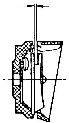
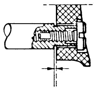
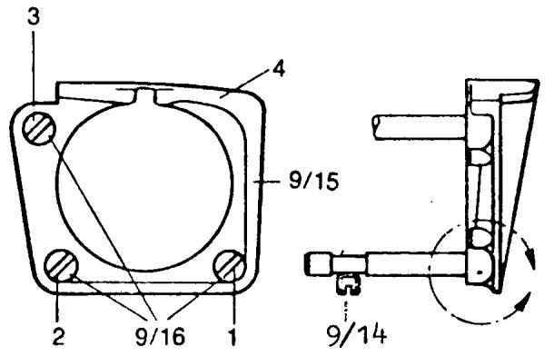
SHUTTLE COVER CLEARANCE
ALL FLAT-BED MODELS
Loosen half a turn the two screws 4, Fig. 28 which secure the retainer 2. Screw off the shuttle cover and replace the hook with adjusting gauge 41 11 649. See that the two lips on the gauge are horizontal in the shuttle cover, so that the cover is guided up sideways in line with the hook. When tightening up the shuttle cover again, take care that the re
tainer is taken up carefully.
Adjust the hook clearance by carefully pressing at the same time on the screws 1 and 3, and pressing uniformly so that screw 3 is not pressed deeper inwards than 1. Retighten the screws 4, Fig. 28.
Before fitting in the hook again make a final check to ensure that the correct clearance has been obtained. With light pressure on the adjusting gauge, feel that it is neither pinched nor has any clearance. When turned slowly the adjusting gauge should give a light resistance.
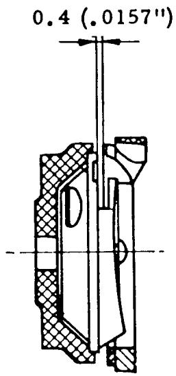
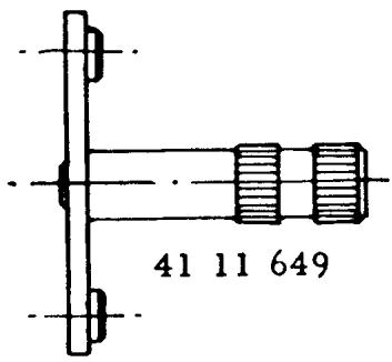
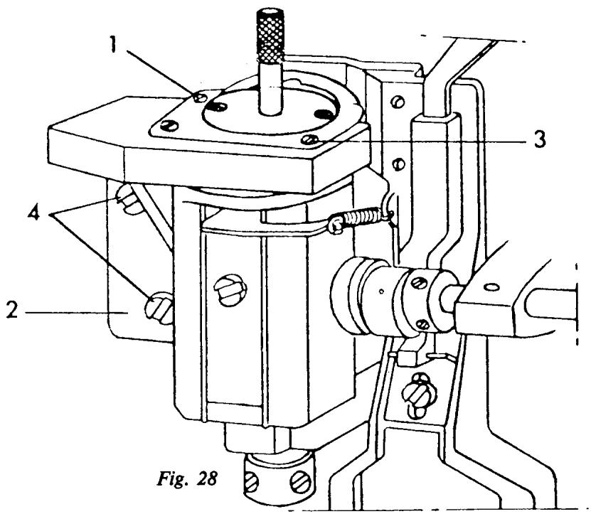
FEED TEETH ALIGNMENT
REQUIREMENT
The feed teeth should be aligned parallel to the slots of the stitch plate.
ADJUSTMENT
Turn the handwheel until the feed teeth are at their highest position. Remove the stitch plate and loosen the 2 mounting screws (10/2). Remount the stitch plate. Manually shift the feed teeth until they are aligned parallel to the stitch plate. Carefully remove the stitch plate so the feed teeth do not shift. Hold the feed teeth and securely tighten the mounting screws.
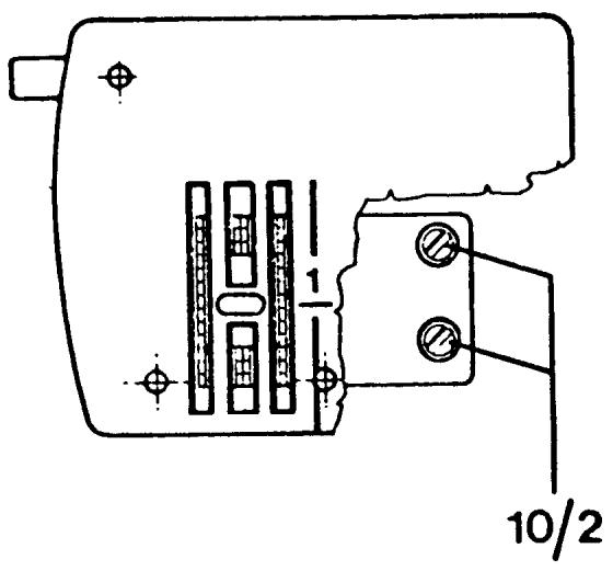
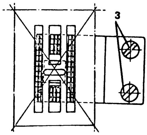
LEFT TO RIGHT CENTERING OF THE FEED TEETH
REQUIREMENT
The feed teeth should move freely in the stitch plate grooves.
ADJUSTMENT
Loosen the screw (10/14) on the feed dog carrier. Shift the carrier until the feed teeth are centered in the stitch plate slots. Tighten screw (10/14).
NOTE
To set this adjustment on earlier models, see following page.
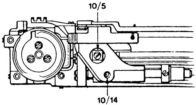
LEFT TO RIGHT CENTERING OF THE FEED TEETH
MODELS: 6310, 4310, 3310, 1310, ALL FLATBED MODELS
REQUIREMENT
The feed teeth should move freely in the stitch plate grooves.
ADJUSTMENT
Loosen screws (1) and (2). Move the feed bar and the pivots (3) until the feed teeth move freely in the stitch plate grooves. Tighten screws (1) and (2).
NOTE
Check that the feed bar moves easily and is without play in the bearings against the pivots (3).
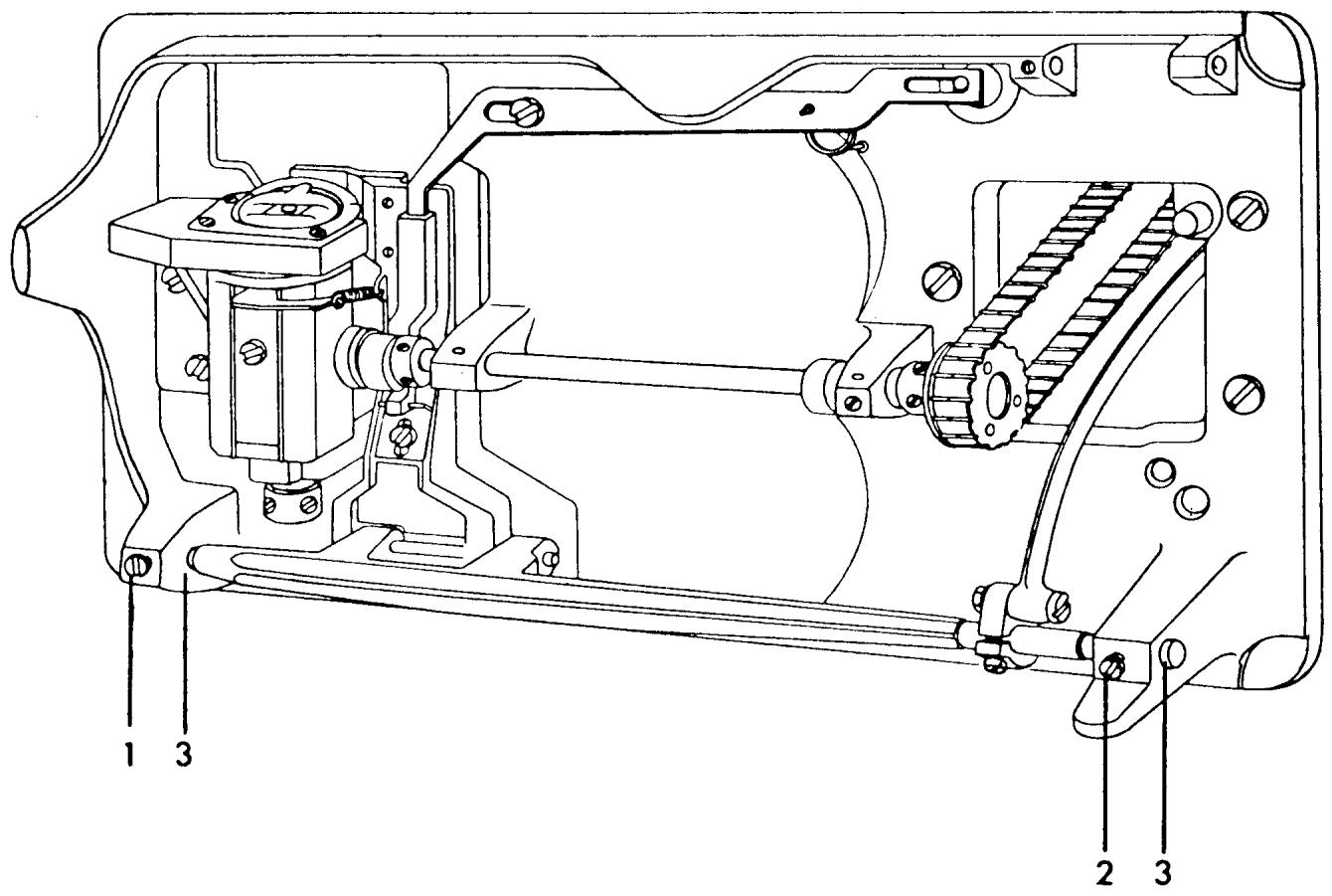
CENTERING THE FEED TEETH FRONT TO REAR
REQUIREMENTS
The feed teeth must not strike against the stitch plate when the machine is set at the maximum stitch length, neither at forward nor reverse feeding.
ADJUSTMENT
Turn the handwheel until the needle bar is in its highest position. Set the stitch length knob at zero. Undo screw (10/5) and looking from the end of the open arm position the feed teeth in the center of the stitch plate grooves. Tighten screw (10/5). Check according to above.
NOTE
To make this adjustment on older style machines see the following page.
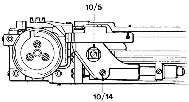
CENTERING THE FEED TEETH FRONT TO REAR
MODELS: 6310, 6320, 4310 3310 1310 49, 51, 71, ALL FLAT-BED MODELS
REQUIREMENTS
The feed teeth must not strike against the stitch plate when the machine is set at the maximum stitch length, neither at forward nor reverse feeding.
ADJUSTMENT
Set the stitch length knob at position 4, back off screw (1). Move the feed dog carrier to the position that the feed teeth move freely in the stitch plate when sewing forwards and backwards. Tighten screw (1).
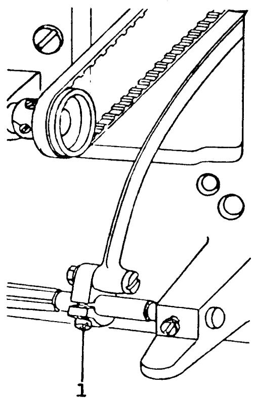
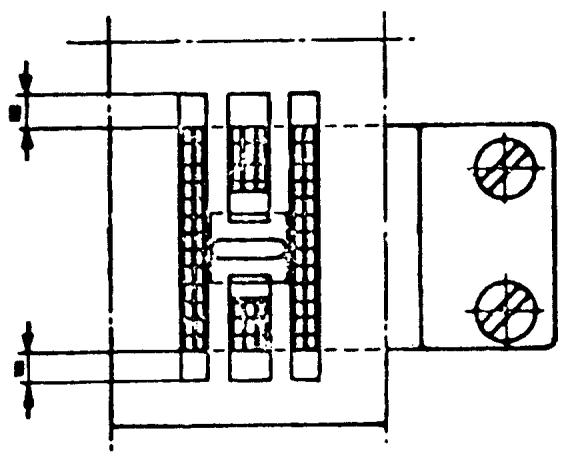
LEVEL OF THE STITCH PLATE
REQUIREMENT
The right and left rows of the feed teeth should be of equal height above the stitch plate.
CHECK
Install the arm sleeve and stitch plate. Place the feed dog height gauge over the feed teeth.
Looking straight through determine if the requirement is met.
ADJUSTMENT
Locate the small adjustment screw on the arm sleeve, as illustrated. Turn the adjustment screw to raise or lower the stitch plate until there is equal clearance of the feed teeth rows.
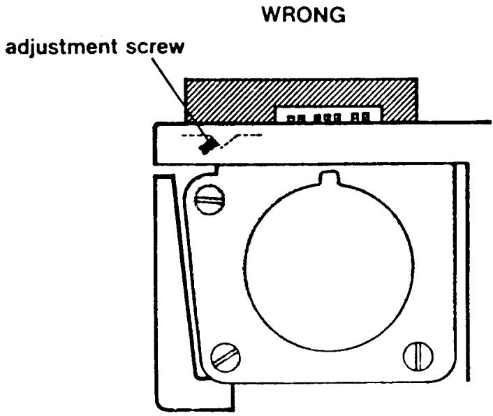
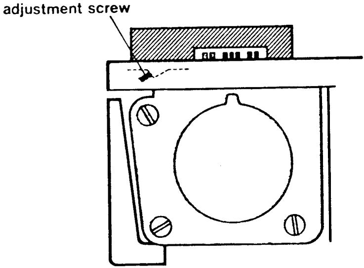
RIGHT
FEED DOG HEIGHT
REQUIREMENT
The height of the feed dog over the stitch plate should be checked with the gauge 41 11 735, which should be placed under the presser foot. The stitch length knob should be set at zero. Turn the handwheel until the feed dog reaches its highest position. The feed dog teeth should be level with the gauge, but should not lift it.
ADJUSTMENT
Through the inspection plate opening in the base plate loosen screw (10/24) and place the feed teeth against the gauge. Tighten screw (10/24).
COMMENT
With the gauge 41 11 735, a feed dog height of 1mm is achieved.
NOTE
For older style machines, i.e., 4310, 3301, 1310, 71, 51, 49 etc. see following page.
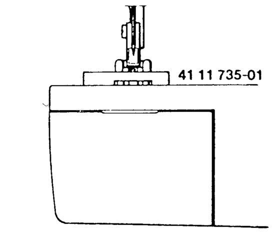
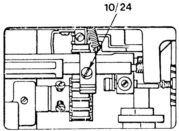
FEED DOG HEIGHT
ALL FLAT-BED MODELS
REQUIREMENT
The height of the feed dog over the stitch plate should be checked with the gauge 41 11 735, which should be placed under the presser foot. The stitch length knob should be set at four. Turn the handwheel until the feed dog reaches its highest position the feed dog teeth should be level with the gauge, but should not lift it.
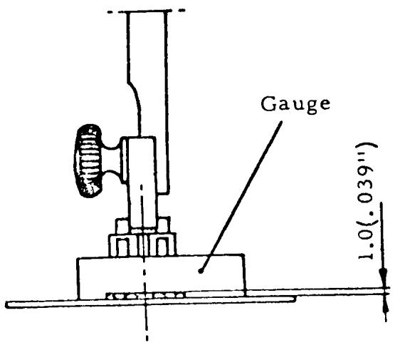
ADJUSTMENT
Loosen screw (1) and raise or lower the feed teeth so that the requirement is met. Tighten screw (1).
Check that the gauge does not move when the handwheel is turned.
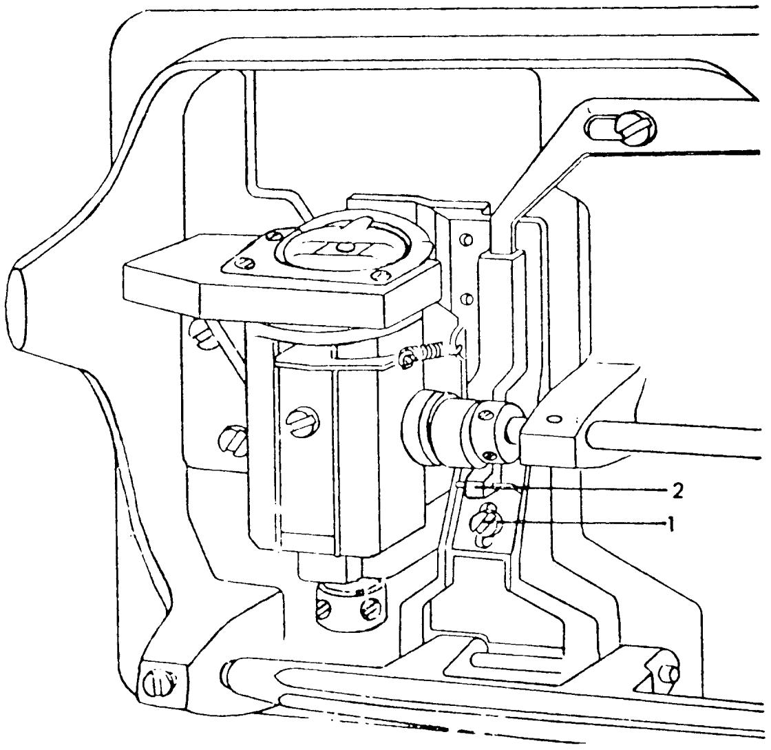
THE FEED DOG DROP
REQUIREMENT
Set the machine at maximum stitch length and drop the feed dogs. Rotate the handwheel forward. Bring the feed teeth to the front forward feeding position. The front edge of the feed teeth should clear the shuttle cover.
ADJUSTMENT
Support the machine level on its back. Through the inspection plate opening in the base plate is the adjustment screw (10/28). Turn the adjustment screw clockwise to raise the support level, and counterclockwise to lower it. 10/28
COMMENT
The adjustment screw is set in a clear nylon mounting block. This mounting block is loose and under no circumstances should it be tightened.
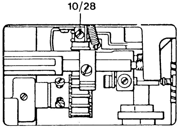
FEED TIMING
CHECK
Set the stitch length dial to 2.5 Rotate the handwheel and bring the needle bar to its highest point. Press the reverse button in then release, in then release, etc. in a fast motion. Notice the feed teeth are traveling front to rear. Continue engaging the reverse button and slowly rotate the handwheel forward until the feed teeth stop moving. The tip of the needle should measure 14.0mm above the level of the stitch plate.
COMMENT
Use the feed dog height gauge to make the measurement which is 14mm wide. Position the gauge level on the stitch plate surface (the feed teeth must be lowered). The needle tip should come right to the edge of the gauge.
ADJUSTMENT
Loosen screw (7/8) on the feed eccentric. Rotate the handwheel to raise or lower the needle until the needle tip comes level with the gauge. Tighten screw (7/8).
NOTE I The feed eccentric is spring-loaded, so when screw (7/8) is loose it will want to rotate backward. Use a screwdriver or a finger to prevent this. If it does happen and the position is lost turn the feed eccentric collar until the screw (7/8) is facing out and if thread take-up lever is in an up position tighten screw (7/8) and start the adjustment again.
NOTE II For older style machines see the following pages.
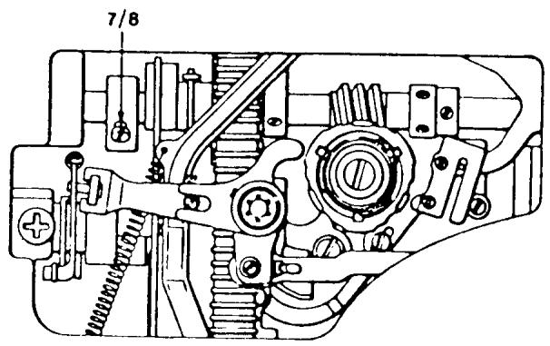
FEED TIMING
MODELS: 6310, 4310, 3310, 1310, ALL FLATBED MODELS
This adjustment is done in the same way as the preceding page with these exceptions:
- When the feed teeth stop moving, the tip of the needle should measure 12 to 14mm above the level of the stitch plate.
- On the feed eccentric there are two and sometimes three adjustment screws. In the case where there are more than one color screw, always loosen just the silver screw(s).
NOTE I This adjustment ensures the feed teeth are not moving the fabric while the needle is either entering or leaving the fabric.
NOTE II For models 6310, 4310, 3310, 1310, the height eccentric must also be set. See the following page.
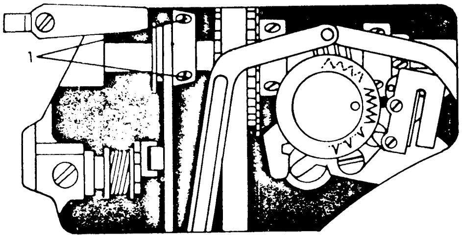
SETTING THE HEIGHT ECCENTRIC
MODELS: 4310, 3310, 1310, FLAT-BED ALL MODELS
CHECK
Set the stitch length knob at 4. Rotate the handwheel until the thread take-up lever is in its lowest position, making sure the feed teeth are moving upward.
At this point, the top of the feed teeth should be level with the stitch plate.
ADJUSTMENT
Loosen screws (1), and turn the height eccentric until the above position is reached. Tighten screws (1).
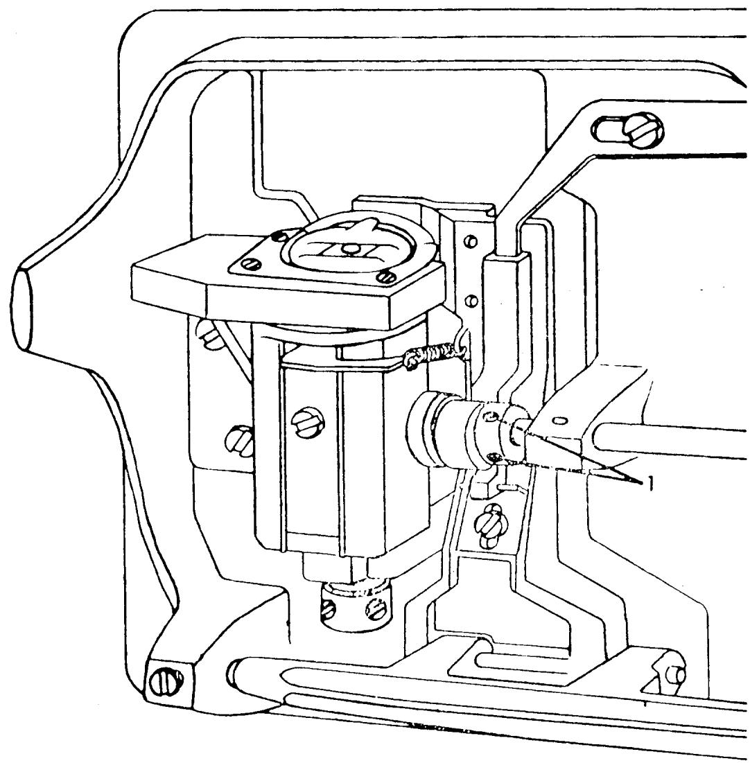
ALIGNMENT OF THE REVERSE ARM CAM FOLLOWER
REQUIREMENT
Install the A programmer, Set the stitch selector at the blue symbol. Turn the handwheel until the cam follower (11/22) reaches the highest point of a cam lobe. The cam follower should now meet the programmer in the middle of a cam disc.
ADJUSTMENT
Loosen the screw (11/21). Move the cam follower in or out to meet the requirement.
Tighten screw (11/21).
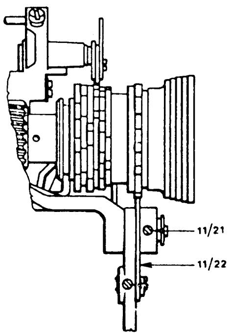
THE RETRACTION OF THE REVERSE ARM CAM FOLLOWER
REQUIREMENTS
Install the A programmer and set all control dials to the blue symbol. Turn the handwheel until the cam follower (11/22) is on top of a cam lobe. Turn the pattern selector dial and set it half way between the yellow and blue symbol. The tip of the cam follower should retract 0.2 to 0.3mm from the cam lobe.
ADJUSTMENT
Loosen the locking nut (2). Turn the inner adjustment screw (3)
counterclockwise to increase the clearance, clockwise to decrease. Secure the locking nut (2). On the older version reverse arms loosen the locking screw (11/25). Turn the adjustment screw (11/23) left or right to obtain the desired clearance. Secure the locking screw (11/25).
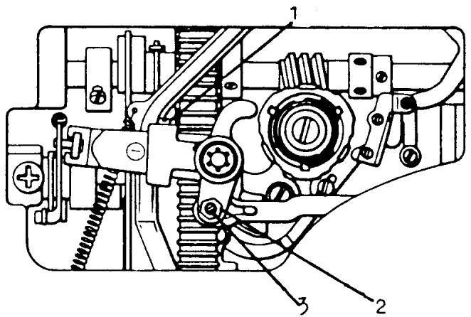
New version
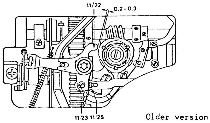
HEIGHT AND ALIGNMENT OF THE PRESSER BAR
REQUIREMENT
The presser bar should be set in such a way that when raised it reaches 6 to 7mm . When it is lowered the presser bar must be parallel to the stitch plate.
ADJUSTMENT
Snap on the regular zigzag presser foot. Place the presser bar gauge directly under the foot. The gauge should fit under the foot with a slight resistance. Check to see that the edge of the gauge is parallel to the seam allowance mark on the stitch plate. To make an adjustment loosen the set screw (6/39). Twist the gauge so that its edge is parallel to the seam allowance mark. From the top of the machine, press down firmly on the presser bar and then secure the set screw (6/39).
NOTE
For earlier model machines, the presser bar height should be set at 6mm . On later series machines having the new style needle clamp, the presser bar height should be set at 7mm .
COMMENT
On the underside of the button-hole foot is a guide which steers the fabric. If the presser bar is not aligned properly, the columns of the buttonhole will be affected.
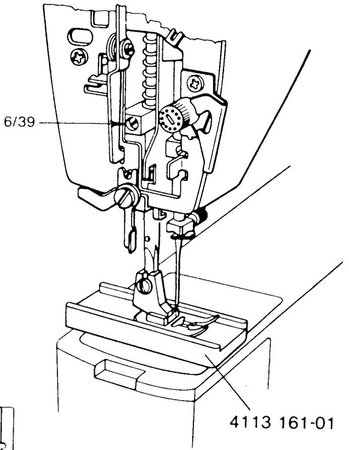
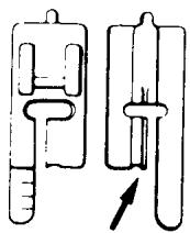
UPPER THREAD TENSION RELEASE
REQUIREMENT
When the presser bar lifter is down, the lever for the thread tension release (1) should not touch the release arm (2).
CHECK
Raise the presser bar lifter and remove the thread tension knob. Check to see that the tension discs separate enough for two threads to pass through on either side. Lower the presser bar and check that the thread tension release arm has play.
ADJUSTMENT
The lever for the thread tension release can be adjusted by eccentric screw (3). Turn it clockwise to decrease the separation of the discs, and counterclockwise to increase the separation.
NOTE
To make this adjustment on older series machines see the following two pages.
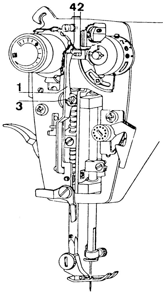
UPPER THREAD TENSION RELEASE
MODELS: 6020, 6010, 3310, etc.
REQUIREMENT
When the presser bar lifter is up, the thread tension discs should have enough clearance to accept 2 sewing threads on each side.
ADJUSTMENT
With the face plate door closed, turn the adjustment eccentric (1) until the correct clearance between the discs is obtained.
NOTE
To make this adjustment on older series machines, see the following page.
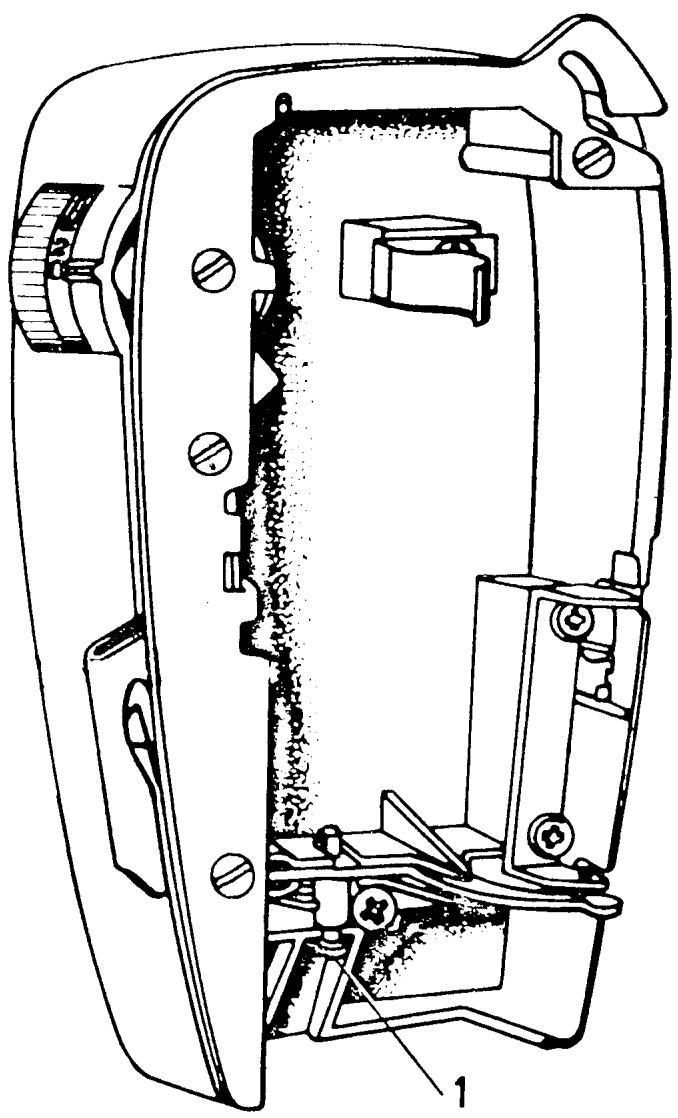
UPPER THREAD TENSION RELEASE
MODELS: 2000, 21, 19, 8, 71, 51, 49, etc.
REQUIREMENT
When the presser bar lifter is at its lowest position the distance between the thread tension release lever and the thread tension release pin should be 1.5mm
ADJUSTMENT
The distance can be adjusted by turning the eccentric screw (1).
COMMENT
When the presser bar lifter is at its highest position the function of the thread tension release lever is to force the thread tension release pin into the thread tension assembly. The result of this is that the pressure on the thread tension discs is released.
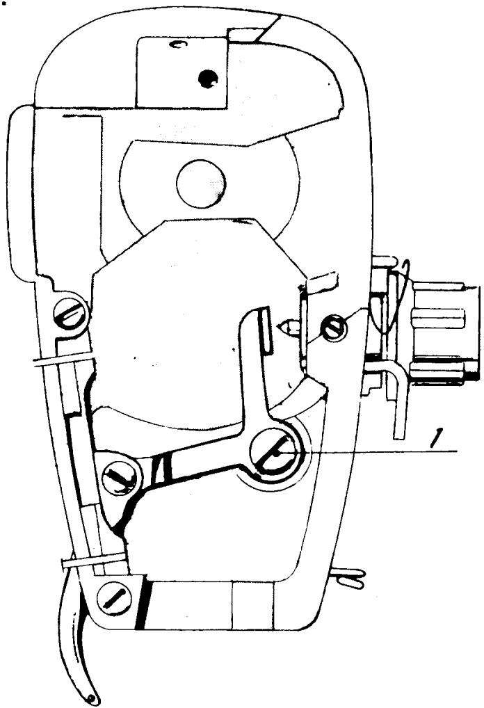
SETTING THE UPPER THREAD TENSION
COMMENT
To set tensions use a medium weight cotton fabric such as muslin. The quality and fiber content of the thread has a definite effect on the tension balance. Use a high quality sewing thread. Install a size 80 needle and thread the sewing machine in the normal way.
Explained are two ways of setting the upper thread tension.
ADJUSTMENT I
Remove the thread tension knob (1). Lower the presser bar lifter. Turn the thread tension dial until there is some separation of the tension discs. Now turn the dial the other way until the discs just come together. Install the thread tension knob lining up the zero with the indication mark. Turn the tension dial to the red dot. The top tension should now be close to the required tension.
ADJUSTMENT II
Remove the thread tension knob (1). Lower the prsser bar. By looking straight on notice that the needle is centered in relation to the presser foot ankle. The thread tension is correct when the thread is pulled to the rear right corner of the stitch plate and the needle deflects parallel with the right edge of the ankle. Turn the tension dial to meet this requirement. Install the thread tension dial at the red dot. Pull the thread to deflect the needle and hold this position. Take hold of the tension dial and rapidly turn it to the buttonhole symbol. The needle should move as the thread tension is relaxed.
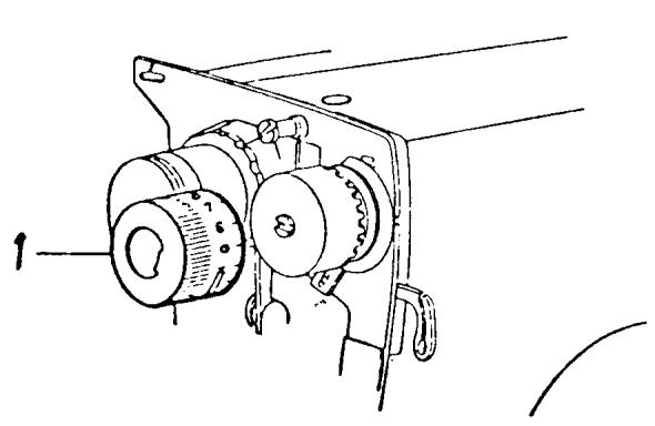
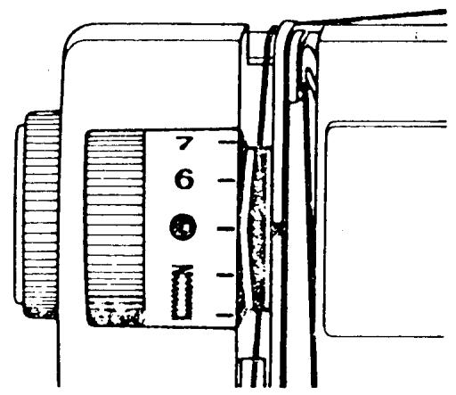
SETTING THE THREAD TENSION OF THE BOBBIN CASE
REQUIREMENT
The thread tension spring of the bobbin case should give the resistance of 20-24 grams when pulling the thread slowly.
ADJUSTMENT
Check that the tension spring is not damaged and remove any loose pieces of thread or lint which may be under it. This can be tested by using something weighing approximately 22 grams. It is possible to use a stitch programmer. Fasten the thread in the programmer and hold the bobbin case in a way that the thread comes out vertically in the direction of the projection on the bobbin case. If the thread tension spring is set correctly, the weight of the programmer will slowly withdraw the thread from the bobbin. Adjust by turning screw (9/36).
COMMENT
The best way to test that the tensions are set correctly is to set the stitch width knob at 4 and stitch length at 21/2 . Proper thread tension is set when the lower thread is pulled directly to the corners of the zigzag on the underside of the fabric.
NOTE
The type of presser foot as well as the fabric is an important factor in obtaining the proper results.
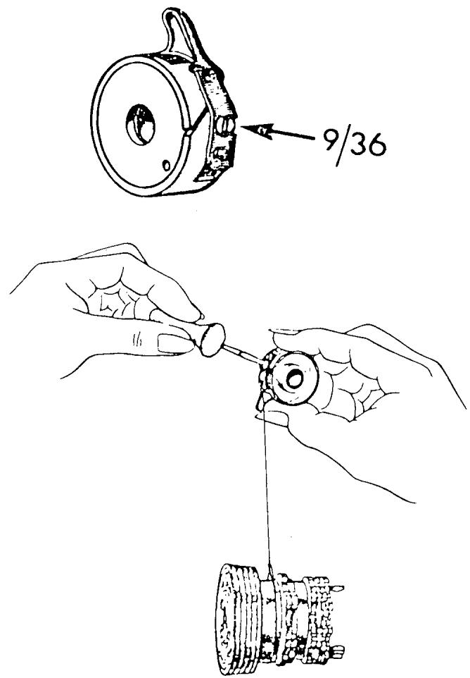
THREAD FEEDING (CHECK) SPRING
REQUIREMENT
The casing (1) should be set so that the thread feeding spring has finished its movement when the eye of the needle reaches the fabric.
ADJUSTMENT
Have machine threaded in the normal way. Set the stitch length to 4. Take 4 or 5 stitches and test requirement. To adjust turn the adjustment casing clockwise to increase the spring's travel and counterclockwise to decrease. Retest until requirement is met.
COMMENT
When the thread feeding spring stops moving there should be a loop of thread formed in front of the needle. The thread loop should be fairly straight, but relaxed.
NOTE
To do this adjustment on older style machines see the following three pages.
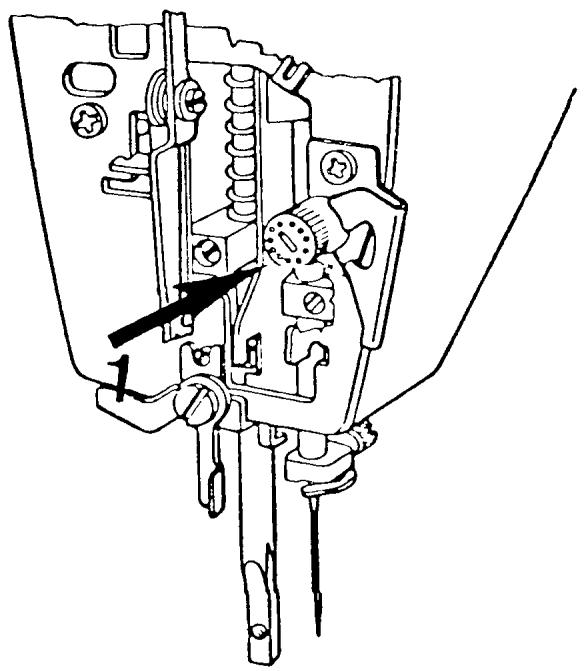
THREAD FEEDING (CHECK) SPRING
MODELS: 6020, 6010, etc.
REQUIREMENT
Set the machine at stitch length 2.5. Have machine threaded in the normal way. Sew 4 - 5 stitches. Then turn the handwheel forward in the running direction until the needle eye just reaches the fabric. At this point the thread feeding spring should have completed its movement.
ADJUSTMENT
Raise or lower the adjustment lug (2) until the requirement is met.
COMMENT
When the thread feeding spring stops moving there should be a loop of thread formed in front of the needle. The thread loop should be fairly straight, but relaxed.
NOTE
To do this adjustment on older style machines see the following two pages.
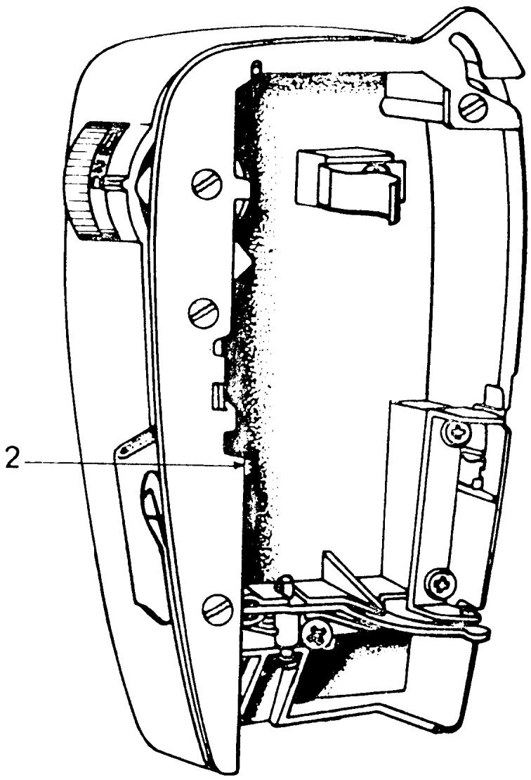
THREAD FEEDING SPRING
MODELS: 49, 51, 71, etc.
REQUIREMENT
The same as the preceding page.
ADJUSTMENT
To adjust move the regulating lever (3). If the lever is moved to the left the travel of the spring will increase and vice versa.
COMMENT
When the thread feeding spring stops moving there should be a loop of thread formed in front of the needle. The thread loop should be fairly straight, but relaxed.
NOTE
To do this adjustment on machines without the regulating lever (3), see the following page.
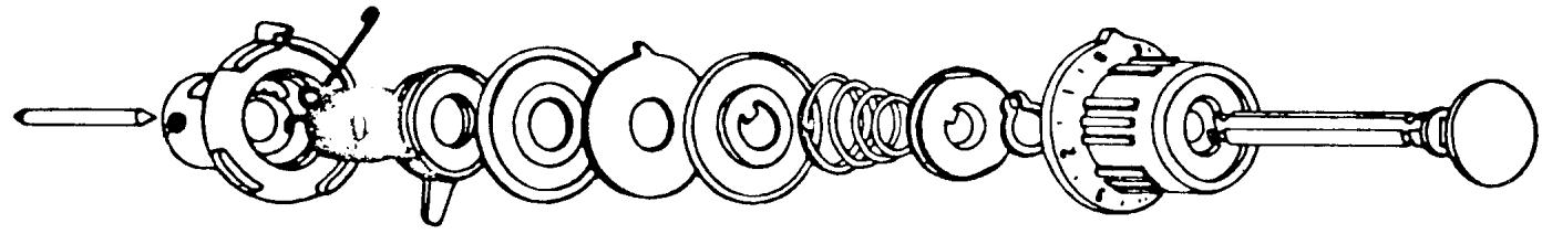
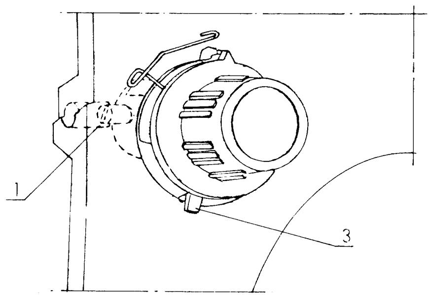
THREAD FEEDING SPRING
MODELS: 21, 51, 71, 7
REQUIREMENT
Same as the preceding two pages.
ADJUSTMENT
Loosen screw (1) and insert a screwdriver into the end of the tension stud. Then turn the entire tension assembly with a screwdriver to the position where the requirement is met.
Tighten screw (1).
COMMENT
When the thread feeding spring stops moving there should be a loop of thread formed in front of the needle. The thread loop should be fairly straight, but relaxed.
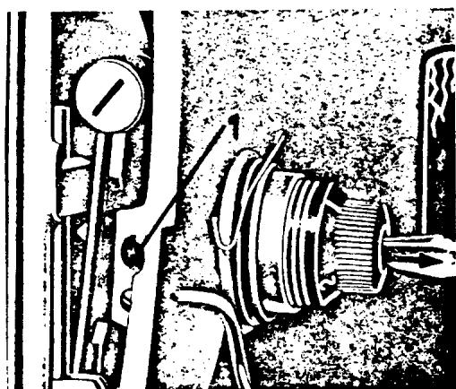
BUTTONHOLE COLUMN EQUALIZATION
REQUIREMENT
When the indication marks on the reverse button and reverse button cap are lined up the columns of the buttonhole should be equal.
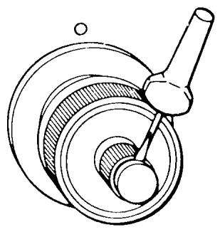
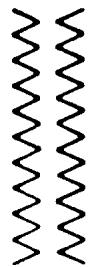

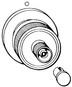
ADJUSTMENT
Sew steps 1 and 3 of the buttonhole. Check the button-hole columns as per requirement. If an adjustment is needed, first turn the outer knob of the reverse button to its correct position; 3:00 o'clock on the latest series of machines and 12:00 for older series machines. Remove the reverse button cap. Turn the inner adjustment nut counterclockwise to increase the density of the column on the right side, and clockwise to decrease the density.
NOTE
Another way to remember which way to turn the nut -- always turn the nut towards the tight side.
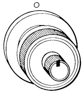
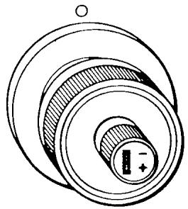
BUTTONHOLE CUTTING SPACE
REQUIREMENT
The proper cutting space is equal to two sewing threads laying side by side between the buttonhole columns.
ADJUSTMENT
The screw (12/1) is the adjusting screw. To increase the cutting space turn the screw clockwise. To decrease the cutting space turn the screw counterclockwise.
COMMENT
The adjustment of the cutting space affects the width of the zigzag. When the cutting space is increased, the zigzag width is reduced and vice versa. Recheck the machine for zigzag on a straight stitch.
NOTE
To do this adjustment on machines without an automatic buttonhole mechanism, see the following page.
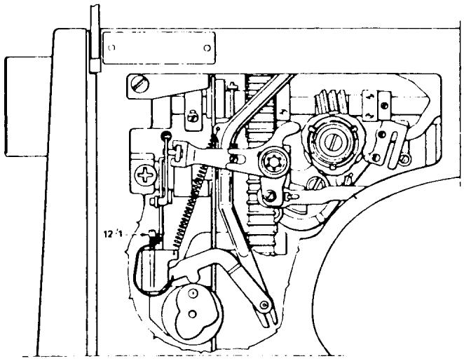
BUTTONHOLE CUTTING SPACE
MODELS: 6310, 3310, 1310, 1000 and 3000 SERIES MACHINES
REQUIREMENT
The proper cutting space is equal to two sewing threads laying side by side between the buttonhole columns.
NOTE
On these model machines this adjustment directly affects the width of the zigzag.
ADJUSTMENT
Sew a test buttonhole. If adjustment is necessary loosen screw (1). It can be reached through the inspection plate opening in the base plate. The cutting space is increased by moving the link (2) downwards. The cutting space is reduced by moving the link upwards.
COMMENTS
Check the zigzag width in the stitch plate. Check that the seam former is not worn. And check that the cam follower retracts over the cam lobe when the stitch width knob is turned from 4 to 0.
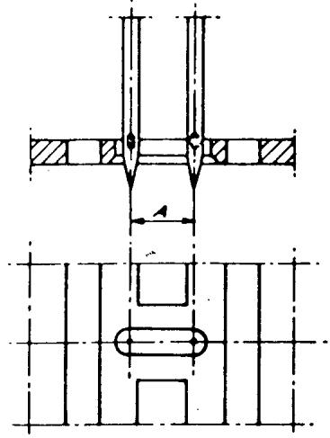
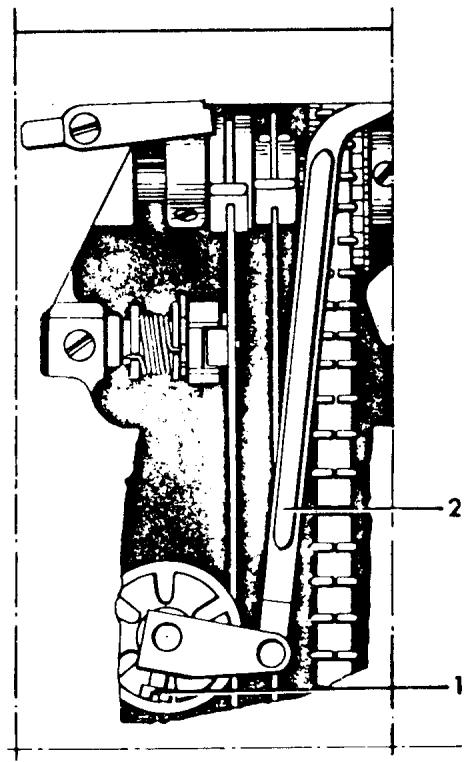
REVERSE FEED EQUALIZATION
REQUIREMENT
Install the A programmer, and turn all control settings to the yellow area. Make sure the stitch length is centered in the yellow area. Sew a seam 6-8 inches long. Remove the fabric and evaluate the elastic straight stitch for equal forward and reverse feeding. When this is correct, there will be almost perfect holes at the beginning and end of the stitch.
ADJUSTMENT
To make a corrective adjustment on the new version reverse arm, turn the adjustment screw (1) clockwise to increase the pattern density, counterclockwise to elongate the pattern. On machines with the older version reverse arm, first loosen the locking screw (2), then turn the eccentric (3) as described before.
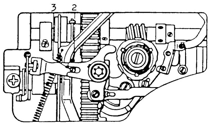
Older version
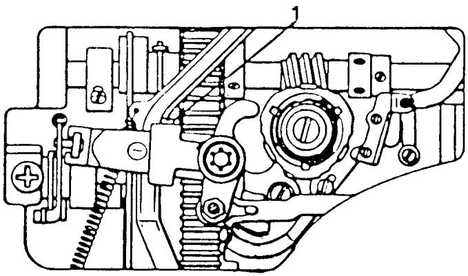
New version
THE WORM GEAR
THE RE-SETTING OF THE FEEDING MOVEMENT
REQUIREMENTS
Install the A Programmer. Set all the controls to the blue symbol and sew a seam 8 to 10 inches long to evaluate the configuration of the overlock pattern. The seam on the left side should be perfectly straight.
COMMENTI
A direct relationship exists between the movement of the zigzag and the feeding of the automatic reversing patterns.
ADJUSTMENT
If there is a fault in the pattern, turn the pattern selector to the white dot and set the width at O. Loosen one set screw (7/2) on the worm gear. Rotate the handwheel and loosen the other set screw. Hold the worm gear stationary and against the positioning collar. Rotate the handwheel backward and observe one quarter inch movement of the needle bar. Secure the set screw and retest the pattern. The seam on the left side should be perfectly straight.
COMMENT II
This setting of the worm gear gives a more functional setting than that of timing the zigzag movement. It is not necessary for the zigzag movement to be symmetrical.
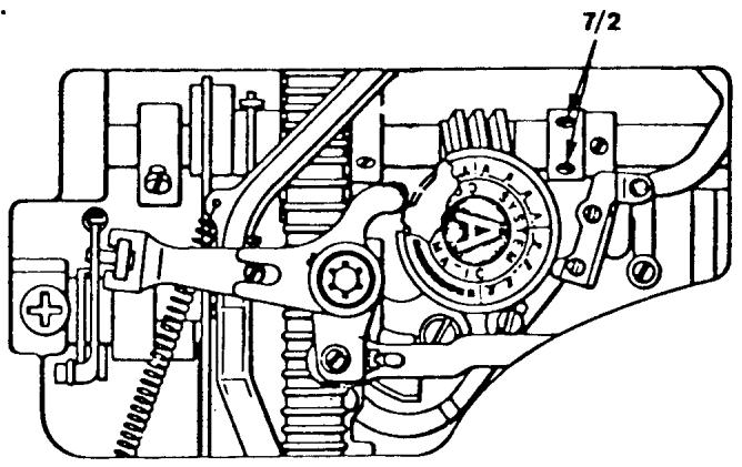

CORRECT AND INCORRECT BOBBIN WINDING
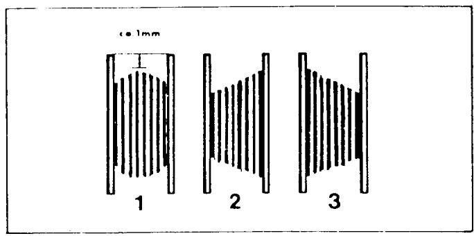

Fig. 1 illustrates how a correctly wound bobbin should look. If the bobbin winds unevenly, adjustment can be made in the following way. First remove the covering until the screw which holds the thread guide in place is accessible. (Note that the screw underneath, which connects the belt guard to the rear cover, should remain untouched). If the bobin winding looks like example 2, turn the screw clockwise until winding is even. If it looks like example 3, check that the bobbin is properly pressed onto the shaft. If this is in order, turn the screw counterclockwise until winding is even.

THREAD TAKE-UP LEVERSLIDE BEARING REMOVAL
COMMENT
The replacement of the slide bearing is the same for most models. The same basic principles of removal apply to all models.
STEPS FOR REMOVAL
- Rotate the handwheel and place the thread take-up lever in its highest position.
- Turn the pressure control dial to the darning symbol.
- Remove the four screws (1, 3, 4 and 5) for the thread tension mounting plate. NOTE A
Before removing the mounting plate, observe the presser bar control lever (2), notice how the yoke fits above the nylon washer and the spring on the presser bar.
NOTE B
On machines with fold-down handles, after removing the thread tension mounting plate, reinstall the handle mounting screw (1).
- Remove the two mounting screws (6) and dismount the thread take-up lever.
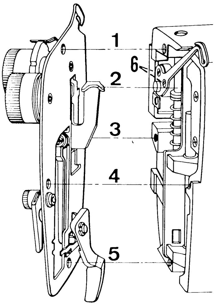
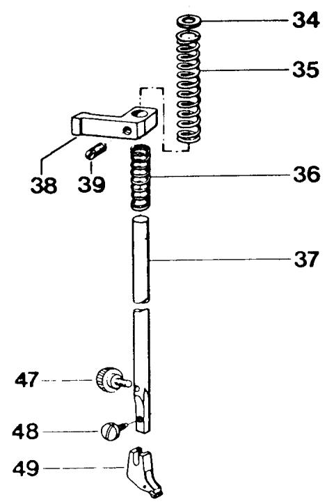
Fig. 1
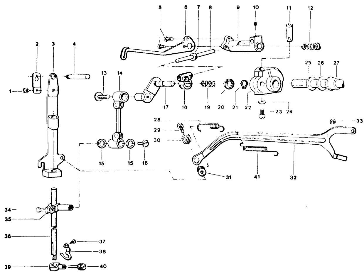
FiG.2
SLIDE REMOVAL CONTINUED
- Remove the presser foot holder mounting screw Fig. 1 (48) and remove the presser foot ankle Fig. 1 (49).
- Loosen the screw Fig. 1 (39) in the presser bar guide.
NOTE
Before removing the presser bar observe the position of the presser bar components Fig. 1 (34, 35, 38, 36).
- Slide the presser bar up, and at the same time, remove the small lower spring Fig. 1 (36), presser bar guide Fig. 1 (38), presser bar tension spring Fig. 1 (35), and the nylon washer Fig. 1 (34).
- Remove the needle bar frame return spring Fig. 2 (28). Use a spring tool, reach in and disconnect the spring from the edge of the casting.
-
Separate the draw rod at the connection to the needle bar frame by removing the locking screw Fig. 2 (29) and adjusting nut Fig. 2 (30). Notice the washer Fig. 2 (31) is between the draw rod and needle bar frame.
-
Remove any needle from the machine.
- Rotate the handwheel and position the needle bar down about 12 its throw. Pivot the needle bar frame outward. Then remove the mounting screw Fig. 2 (13) and separate the connecting rod Fig. 2.(14) from the crank stud Fig. 2 (17). NOTE
On all models, the mounting screw Fig. 2 (13) has left-hand threads. Turn the screw clockwise to remove.
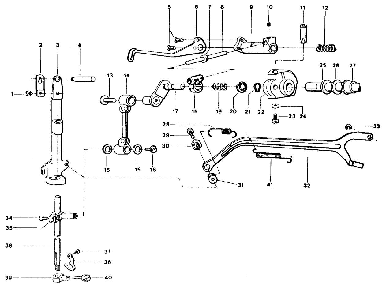
Fig. 2
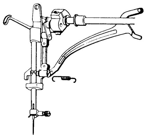
Fig. 3
SLIDE REMOVAL CONTINUED
- Looking from the rear of the machine rotate the handwheel until the large set screw Fig. 2 (23) is visible. Loosen the screw 212 turns. With the tip of the screwdriver on the screw head, tap inward, driving the set screw flush against the needle bar crank collar.
- From the head of the machine take hold of the thread take-up lever mounting frame Fig. 2 (9) and remove from the machine. In some cases the crank collar Fig. 2 (22) will come out too. Prevent this by placing a finger on it so it remains in the machine.
- Remove the crank stud Fig. 2 (17) and slide Fig. 2 (18).
COMMENTS FOR INSTALLING THE NEW SLIDE TO CRANK STUD
When installing the new take-up slide bearing to the crank stud, the rounded, tapered area of the slide goes on the crank stud first. Place the small tension spring Fig. 2 (19) and the retention washer Fig. 2 (20) on the crank stud shaft. A true-arc clip Fig. 2 (21) is used to secure the slide to the crank stud. Compress the spring with the retention washer. Fit the clip to the groove on the crank stud shaft.
STEPS FOR INSTALLATION
NOTE The crank stud with slide must be installed with the take-up lever frame. The take-up lever frame slide shaft Fig. 2 (8), as it fits to the bearing, must be installed so that it is at the top of the machine. Position the crank stud Fig. 2 (17) so that the flat is toward the top of the machine. Make sure the flat on the lock bolt Fig. 2 (11) which is in the crank collar Fig. 2 (22) is facing down.
- Place the take-up lever frame on the mounting shaft and fit the crank stud to the crank collar Fig. 2 (22).
SLIDE BEARING INSTALLATION CONTINUED
NOTE
Do not exert pressure or attempt to force the assembly. The assembly will fit smoothly together.
- Prior to securing the mounting screw Fig. 2 (23) on the crank collar, install the thread take-up lever Fig. 2 (6).
- Press inward on the needle bar crank collar Fig. 2 (22) and secure the large mounting screw Fig. 2 (23).
- Remove the thread take-up lever.
- Connect the needle bar connecting rod to the crank stud, mount the screw Fig. 2 (13) and tighten.
- Connect the draw rod to the needle bar frame. First put the washer Fig. 2 (31) between the draw rod and needle bar frame, then install the locking screw Fig. 2 (29) and adjusting nut Fig. 2 (30). Tighten screw.
- Install the needle bar frame return spring Fig. 2 (28).
- Install the presser bar. Start the bar through the casting and put the washer and tension spring on first. Then the presser bar guide and last the small lower spring. Lightly secure the screw Fig. 1 (39) on the presser bar guide.
- Install the thread take-up lever.
- Put the thread take-up lever in its highest position. Install the face plate making sure the yoke on the presser bar control lever is above the nylon washer and spring on the presser bar.
ADJUSTMENTS TO CHECK
A. Centering the zigzag width in the needle plate.
B. Height and alignment of the presser bar.
EXCHANGING THE FIXED CAM AND WORM WHEEL
COMMENT
Changing the fixed cam and worm wheel is nearly the same for all models. There are a couple of differences which are explained in detail. Whenever a difference is explained it is absolutely necessary to follow the instructions to prevent any binding of the machine after installation.
Set the pattern selector to the center needle position and the zigzag width at 0. Support the machine in a level position on its face so the back of the machine is facing you as in Fig. 4.
STEPS FOR REMOVAL
- Remove the mounting screw (1) on the fixed cam guide.
NOTE The screw is spring loaded. The connecting arm for the reverse feed cam follower retraction will keep the screw from coming completely out of the machine. Observe for reinstallation purposes how the fixed cam guide (4) fits into the groove in the fixed cam.
- Grasp the fixed cam (2) and lift it out of the machine.
- Remove the screw (3) in the center of the worm wheel. Notice the position of the steel washer (which is tapered to receive the screw head) and the nylon washer. Leave these both on the screw (3).
NOTE On the model 2000 and the 10 series there is a collar and nylon friction washer which must be removed.
NOTE The 20 series machines employ a C-clip on the worm wheel shaft that must be taken away.
- Remove the worm wheel.
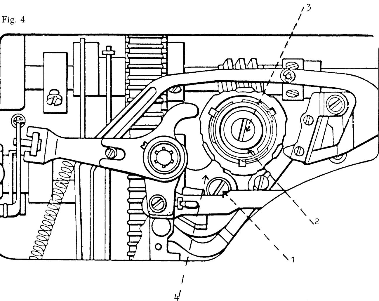
FIXED CAM AND WORM WHEEL INSTALLATION
COMMENT
When replacing either the fixed cam or worm wheel always replace them with the matched set part number 41 15 984-60.
STEPS FOR INSTALLATION
- Mount the new worm wheel on the pattern selector shaft and engage the worm wheel to the worm gear on the main shaft.
- Firmly secure the mounting screw (3).
NOTE Models 2000 and the 10 series have a collar to secure the worm wheel. Turn the pattern selector to left needle position. Mount the nylon friction washer and collar to allow 0.5mm to 1.0mm end play of the worm wheel.
COMMENT
The fixed cam must not bind against the collar. Install additional nylon friction washer(s) as required to maintain the 0.5mm to 1.0mm clearance.
NOTE 20 series machines employ a C-clip to mount the worm wheel. Check that there is 0.5mm clearance.
NOTE Starting with the 30 series machines the worm wheel mounting is controlled by the pattern selector mounting screw. The 0.5mm must be checked after installation to the machine.
NOTE The 40 series machines incorporated a one-piece nylon worm wheel. This worm wheel is longer so the friction washer is not necessary.
COMMENT
If the later style fixed cam and metal worm wheel is to replace a one-piece unit, i.e., 40 series worm wheel, a friction washer will be necessary to maintain the required 0.5mm end play.
Order number 41 10 592-01 nylon friction washer.
WORM WHEEL INSTALLATION CONTINUED
- Fit the fixed cam to the worm wheel aligning the groove in the fixed cam to the key on the worm wheel. With the tip of a screwdriver, make sure the cam guide is in the slot of the cam.
COMMENT
To secure the mounting screw (1) to the cam guide (4) without stripping it, read step 4 below carefully.
4. Set the machine upright. Press inward on the cam guide mounting screw (1) with a screwdriver. At the same time, rotate the pattern selector and draw the cam all the way inside the machine. Continue to press in on the screw. Grasp the fixed cam and carefully move in or out to position the cam guide to the screw. Rotate the screw counterclockwise until the threads engage. Secure the screw.
ADJUSTMENTS TO CHECK
A. Timing of the zigzag.
B. Raise of the cam follower.
C. Zigzag cam follower retraction and alignment.
D. Reverse feed cam follower alignment.
PATTERN MECHANISM, STITCH LENGTH UNIT AND STITCH WIDTH UNIT REMOVAL
COMMENT I
To exchange the zigzag unit it's easier to remove the pattern selector and stitch length device and remove the unit from the rear of the sewing machine. The steps for removal are explained in a sequence that would be used if the stitch width unit were being replaced. Therefore, if the stitch length unit was the only unit to be replaced, it is necessary to remove only the parts directly involved for removing the pattern selector and stitch length device.
COMMENT II
It is recommended that all the parts be laid out in the order and position in which they are removed.
STEPS FOR REMOVAL
- Lower the lamp assembly and remove the light bulb.
- Remove the mounting screw for the lamp bracket. Observe the position of the lamp bracket and how it's mounted.
- Remove the center cover and mounting screw for the pattern selector. Lift off the dial, coil tension spring and color scale.
- Pull out the zigzag dial and engage the unit to position two of the buttonhole sequence. Remove the center cover and mounting screw and lift away the dial, spring and scale.
- From the back of the machine, remove the star washer Fig. 5 (1) with the tip of a screwdriver. Observe how the connecting link Fig. 5 (2) of the reverse arm engages the stitch length device before dismounting the arm.
- Remove the C-clip Fig. 5 (3) that joins the connecting link from the zigzag mechanism to the draw rod. Press inward on the connecting link to separate its connection with the draw rod.
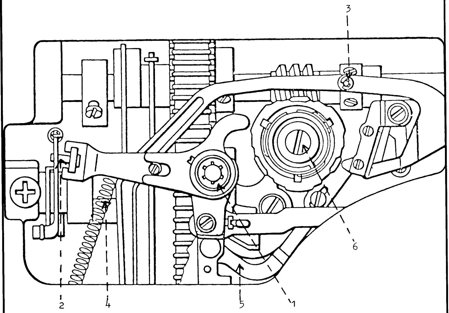
Fig. 5
PATTERN MECHANISM REMOVAL CONTINUED
- Disconnect the spring Fig. 5 (4) attached to the connecting link. The spring is fixed to the zigzag mechanism and may be released.
- Press down on the arm that the connecting link is fixed to. Lift up, separating the link from the arm and remove from the machine.
- The needle position support arm from the buttonhole cam must then be separated from the curved arm of the pattern selector. With the tip of a screwdriver spring load the curved arm Fig. 5 (5) of the pattern selector upward. Applying pressure, shift the support arm for the buttonholer directly to the right. At this point, the support arm for the buttonholer must be lifted out and moved to the left across the face of its connection point with the curved arm of the pattern selector. It is convenient to gently wedge the arm against the stitch regulator fork. This will hold it in a position out of the way during removal of the pattern selector.
- Remove the mounting screw Fig. 5 (6) in the center of the pattern selector.
- Remove the pattern selector by grasping the pattern selector frame and moving it side to side while pulling it out. Once it's out of the machine make the following observations.
OBSERVATION I
How the lamp wire comes up across the front of the pattern selector frame, and then to the rear, over the top of the lamp bracket.
OBSERVATION II
The spring is attached differently to the front of the pattern selector frame, depending on the model.
- Separate the spring from the pattern selector and lift the unit out.
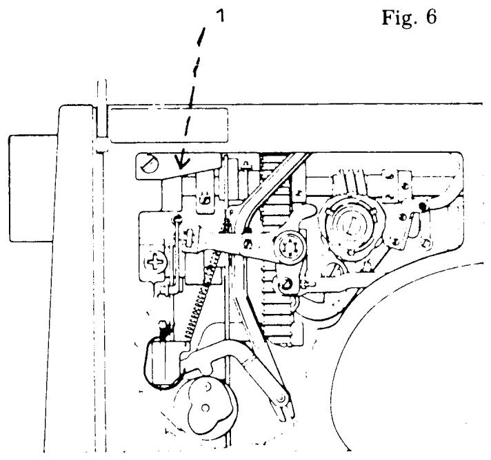
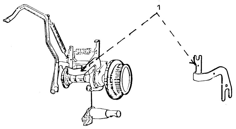
Fig. 7
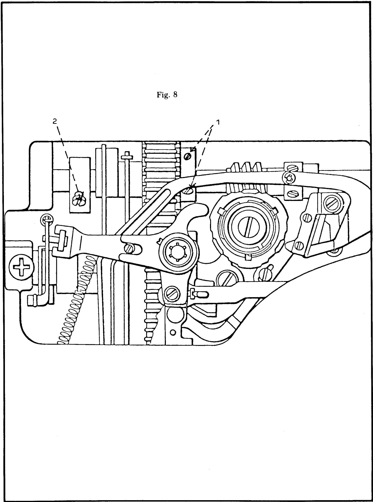
STITCH LENGTH UNIT REMOVAL CONTINUED
- Remove the plate Fig. 6 (1) on the rear of the machine. Observe that the spring is attached to the stitch regulator fork.
- Remove the needle position support arm Fig. 7 (1) for the buttonhole cam. Observe its connection to the buttonhole mechanism.
- Loosen the set screws Fig. 8 (1) on the chain belt sprocket one-quarter turn and shift the sprocket to the right.
- Rotate the handwheel so that the set screw on the feed eccentric is available. Loosen the set screw Fig. 8 (2) and shift the feed eccentric collar to the right separating the slide block on the stitch regulator fork from the stitch length guide. Lightly tighten the set screw.
- Through the inspection plate of the sewing machine, loosen the set screw Fig. 9 (1).
- Separate the stitch regulator fork bearing Fig. 9 (2) from the rocker bar. NOTE
On models 6440, 60 series, and 70 series the fork may be hard to separate from the rocker bar because the lower chain belt sprocket interferes. It may be necessary to spring load the rocker bar to gain the additional clearance. From the rear of the free arm, place a screwdriver against the casting and spring load the arm collar on the rocker bar to the left and hold. Now separate the stitch regulator fork bearing from the rocker bar.
NOTE
For all earlier models a different method is used to separate the stitch regulator fork from the rocker bar. Remove the two C-clips Fig. 10 (1) and slide the pin to the left. Separate the stitch regulator fork bearing from the rocker bar.
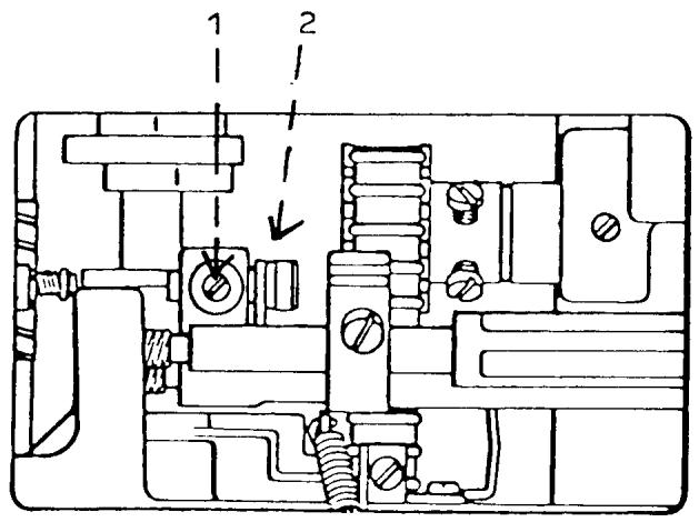
Fig. 9
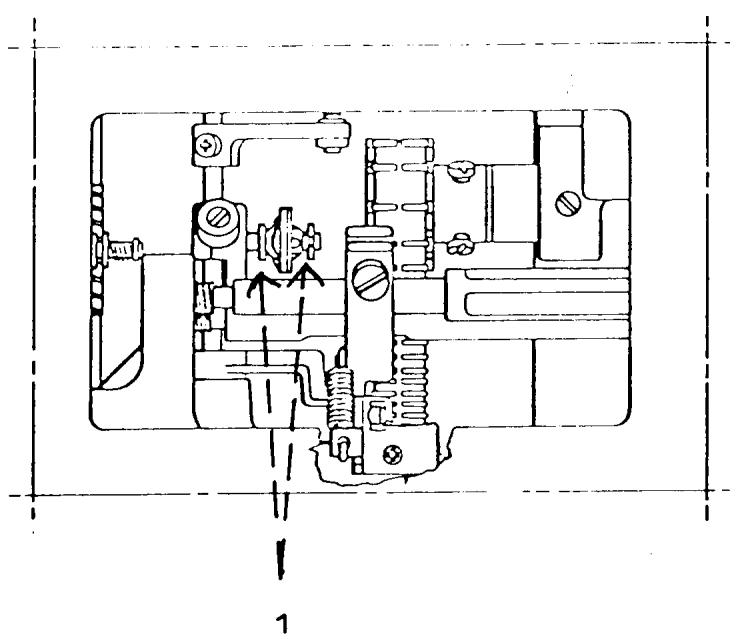
Fig. 10
STITCH LENGTH AND WIDTH UNIT REMOVAL CONTINUED
- Remove the stitch regulator fork by pulling it down through the opening of the bottom plate to one-half its length. Turn the fork clockwise so it is sideways in the machine and remove it from the bottom.
- Remove the stitch length knob and scale by pulling it off. COMMENT
On the latest series of machines there is a tapered nylon ring used to center the stitch length mechanism in the casting. From inside the machine, with the tip of a screwdriver, apply pressure around the outside edge of the nylon ring until it is separated.
- Remove the large mounting screw Fig. 11 (1).
COMMENT
On models with an electronic circuit board the board must be removed from end of the machine.
- Grasp the mounting collar directly underneath the handwheel. Pull and rotate to remove the collar.
NOTE
Observe the hole in the collar. When reinstalling this is placed in alignment with the mounting screw.
- Remove the stitch length mechanism from the machine.
- Remove the mounting screw for the zigzag mechanism.
NOTE
On the latest series machines with the dual idler wheel on the V-belt, there is a spring from the dual idler to the stitch width unit. It must be unhooked.
- Remove the mechanism by lifting it directly out the rear of the machine.
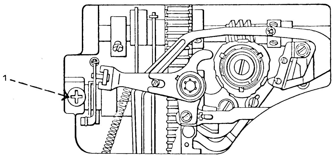
Fig. 11
INSTALLATION OF STITCH WIDTH, STITCH LENGTH AND PATTERN MECHANISMS
COMMENT
Installation of the mechanisms is the opposite of removal. At each stage of installation, it is a good idea to ensure that each mechanism performs the proper function.
STEPS FOR INSTALLATION
NOTE The return spring for the drop feed button is friction mounted to the shouldered area on the front of the frame. When installing the button-hole mechanism, at all times the spring must remain firmly in position on the shouldered area. Also, during installation of the new mechanism, ensure that the drop feed return spring fits into the slotted area in the drop feed button.
- Install the buttonhole mechanism and secure the mounting screw.
- Attach the color scale, spring and the control dial.
- Engage the mechanism to position 2 of the buttonhole.
NOTE
If machine is a late series with the dual idler wheel, the spring from the wheel needs to be connected to the stitch width unit.
- Install the stitch length mechanism.
- Install the mounting collar for the stitch length mechanism. Align the hole in the collar to the screw hole in the casting.
- Install the tapered nylon ring.
- Mount the screw Fig. 11 (1).
- Install the stitch length knob and scale.
continued
- Ensure that the friction plate and slide block are on the stitch regulator fork. Install the fork through the opening in the base plate. Turn the fork sideways so the slide block is facing upwards. Push the fork through the opening over the rocker bar bearing and slide it upwards past the stitch width unit. Once past the stitch width unit turn the fork counterclockwise until it's in the correct position. Push the fork into the feed eccentric cam. Loosen the screw Fig. 8 (2) and move the feed eccentric to the left and install the slide block into the stitch length guide. Tighten screw Fig. 8 (2). Spring load the rocker shaft again and at the same time turn the handwheel until the regulator fork pin is lined up with the bearing. Push the pin inside bearing. Tighten set screw Fig. 9 (1).
Check to see that the reverse button can be pushed in and released without sticking. If sticking occurs there needs to be more play between the stitch regulator fork slide block and the stitch length guide. Loosen screw Fig. 8 (2). Move to the required tolerance, tighten screw Fig. 8 (2).
- Connect the plate Fig. 6 (1) to the spring from the stitch regulator fork. Secure the screw to the plate.
- Install the needle support arm Fig. 7 (1) for the buttonhole cam. Gently wedge the arm against the stitch regulator fork.
- Move the chain belt to the left to its original position and secure the two screws Fig. 8 (1).
- Connect the lamp wire spring to the pattern selector frame in the same manner as it was originally connected.
- Make sure the lamp wire comes over the top of the lamp bracket.
INSTALLATION OF THE PATTERN SELECTOR CONTINUED
- Install the pattern selector.
- Install the mounting screw Fig. 5 (6) and washers.
- Make sure the draw rod guide is in the stitch width cam follower.
- Connect the needle position support arm to the curved arm of the pattern selector Fig. 5 (5).
- Install the connecting link Fig. 12 (1) to the lever arm of the stitch width unit.
- Connect the spring Fig. 5 (4) to the connecting link.
- Connect the draw rod to the link and attach the C-clip Fig. 5 (3).
- Install the reverse lever arm and star washer Fig. 5 (1).
- Mount the lamp bracket to the lamp socket and secure with screw. Install light bulb.
- Mount the pattern selector color scale, spring and dial. Secure with screw. Put on center cover.
COMMENT
After replacing any of the three main mechanisms, it is important to go over the service adjustments.
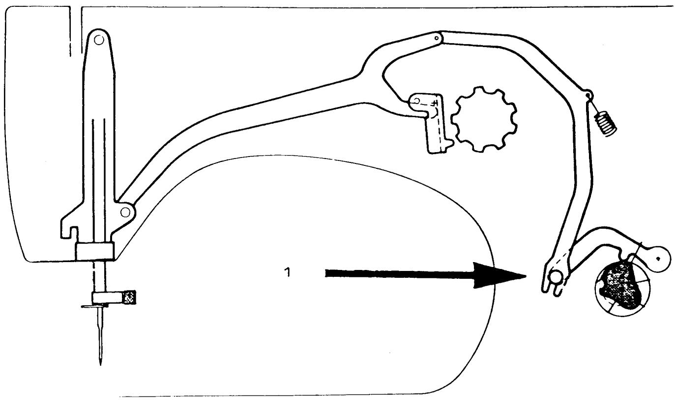
Fig. 12
REDUCTION GEAR REMOVAL AND REPLACEMENT
COMMENT I
The following procedures for removal and replacement of the reduction gear apply to all models beginning with the 20 series.
COMMENT II
On later series models with a circuit board, the board must be removed from the end of the machine.
STEPS FOR REMOVAL
- Rotate the handwheel and position one of the openings on the outside edge of the reduction gear pulley, at the one o'clock position. Remove the mounting screw (14/8).
- Rotate the handwheel and reposition the opening at the 3 o'clock position. Remove the mounting screw (14/9).
- Remove the cog belt.
- Lift the reduction gear out of the machine.
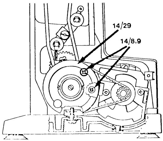
STEPS FOR REPLACEMENT
- Install the reduction gear in the machine. Be sure the V-belt is around the cog with belt pulley.
- Install the cog belt.
- Install the two mounting screws (14/8,9). NOTE
On some models the mounting screw at the 3 o'clock position is the longer one.
COMMENT
The cog belt tension must be set. On the latest series of machines the V-belt tension will also have to be set.
BOBBIN CASE REPAIR
COMMENTS
When inspecting the bobbin case, make sure that the chrome plating has not peeled around the edges. If it has the bobbin case should be exchanged.
If the customer installed the bobbin case incorrectly, it's possible that the tip of the needle could strike the bobbin case on its outside shoulder. This does not interfere with the sewing ability of the machine, and is not a reason for replacement.
If the thread tension spring, the fixed mounting screw or the tension adjustment screw are damaged they should be exchanged.
When inspecting the bobbin case, take a discarded needle and pass the tip of the needle under the thread tension spring to remove thread residue.
Bobbin case complete, part number 40 11 530-02.
Individual replacement parts are identified below:
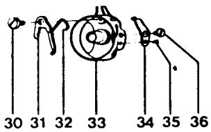
30 41 10 601-01 Shoulder Screw
31 40 11 535-02 Latch
32 40 11 536-01 Spring
33 40 11 531-02 Bobbin Case Housing
34 40 11 781-01 Thread Tension Spring
35 2286200-41 Screw
36 2071211-46 Screw
NOTE
On some earlier models the bobbin case parts differ with numbers (35) which is part number 22 88 125-01 and (36) part number 20 74 260-01.
BOBBIN CASE REPAIR CONTINUED
Make sure the latch (31) moves freely in its mounting on the shoulder screw. If it doesn't a new latch spring (32) should be installed.
STEPS FOR REPLACEMENT OF THE BOBBIN CASE LATCH SPRING
COMMENT
It is necessary when installing a new latch spring to apply a twisting pressure; for this reason, the latch spring has additional length. It's convenient to use a locking tool to hold the spring, in order to apply the twisting pressure.
- Install the spring under the side of the bobbin case through the opening (A).
- The tip of the spring passes over the top and tucks under the latch so the tip protrudes at position (B).
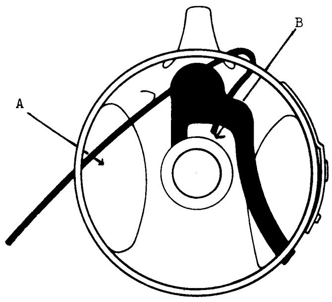
- Twist the holding tool and press the spring over the shoulder area on the bobbin case.
- Release the holding tool for the spring and with the tip of a small screwdriver, from the top of the bobbin case opening, press the spring securely into the shouldered area (C).
- With the edge of a screwdriver push the spring down over the shouldered area on the left inner portion of the bobbin case (D).
- Test the latch to ensure that it is spring loaded and functioning smoothly.
- From the outside of the case, clip the spring as close as possible to the edge (E) with side cutters.
NOTE
It is essential that the spring be cut close to the edge. Any portion of the spring that protrudes will interfere with thread escapement.
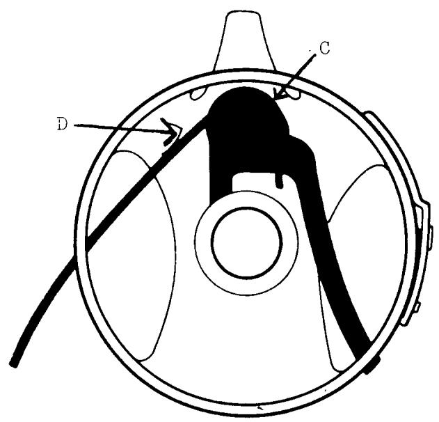
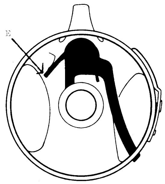
NOTES:
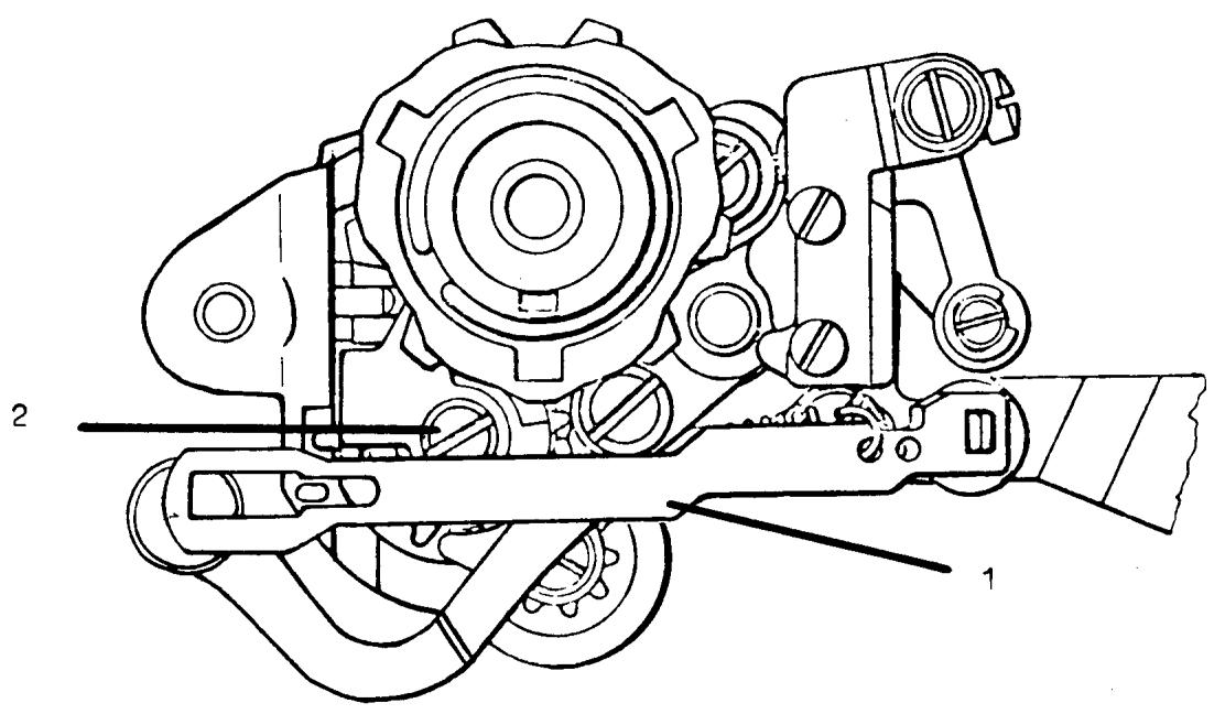
Ill. "A"
COMPONENT REPAIR
PATTERN SELECTOR MODELS 2000 - 6570
The following procedures described to repair defective pattern selectors apply to all models. Design changes to improve the function of the mechanism may vary the method of assembly. When necessary, comments and illustrations will explain the requirements applicable to specific models.
It is suggested parts be laid out in the order and position removed.
TOOL REQUIREMENTS
Box spanner metric size
5mm old style
5.5 mm new style
Tru-Arc pliers
Order 41 11 910
DISASSEMBLY
- Remove connecting link III. A (1). Note the position and the manner the return spring is attached; it will differ between models.
- Loosen the cam guide screw III A. (2). Caution: The screw is spring loaded. Remove the screw and tension spring. Note the small fiber washer and the screw.
- Remove the fixed cam and worm wheel.
COMMENT
On 30 series and later machines the worm wheel position is controlled by the pattern selector mounting screw. Models 2000 and 10 series have a separate collar. Loosen the two set screws and remove the collar, nylon friction washer, and worm wheel.
The 20 series employ a C-clip on the worm wheel shaft.
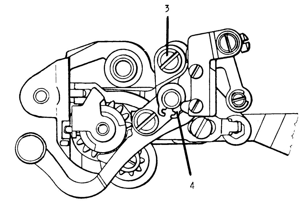
I11. "B"
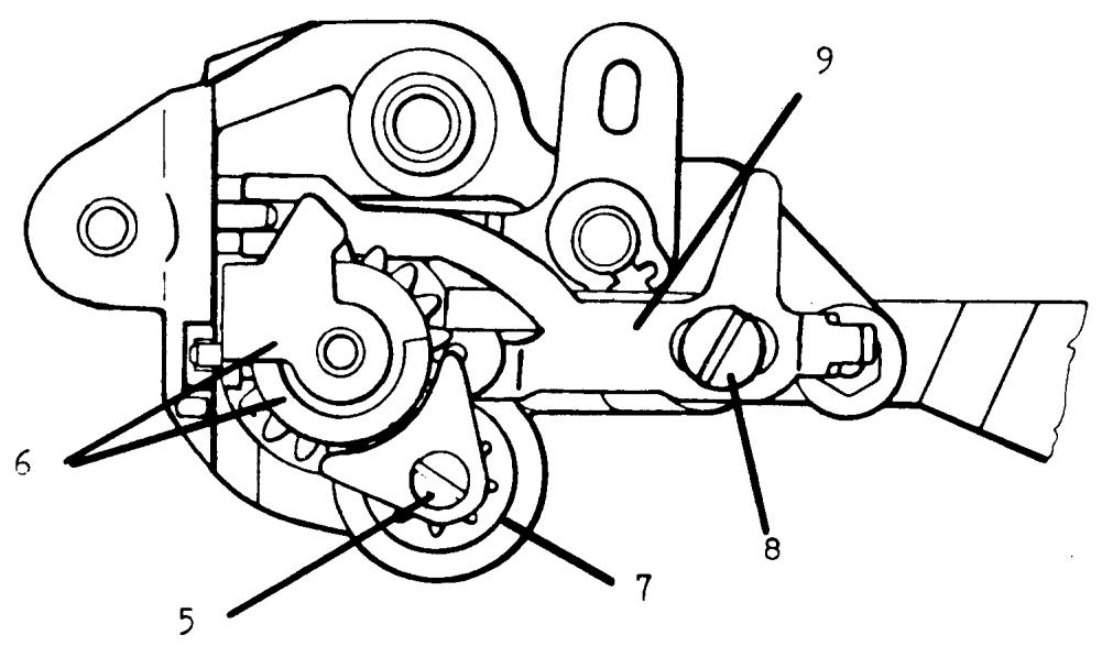
I11. "C"
DISASSEMBLY CONTINUED
- Remove the lock nut and the two spring steel washers from the left needle position eccentric screw III. B (3).
COMMENT
Late style pattern selectors have a friction nut with a nylon insert. Older models have two nuts, one tightens to compress the concave spring steel washers to obtain a friction load for the adjustment screw. The second nut is secured against the first to prevent the assembly from loosening should the adjustment be turned counter-clockwise.
- Remove the Tru-Arc clip III. B (4), lift off the needle position support frame. COMMENT
On later style units the Tru-Arc clip is located behind the needle position support frame and will be removed in step 7. - Remove screw III. C (5) and the mounting guide plate. Lift off the main gear with cam guide (6). Remove the middle gear wheel (7).
- Remove the shoulder mounting screw III. C (8) and lift away the disengaging plate, roller, and retention guide plate (9).
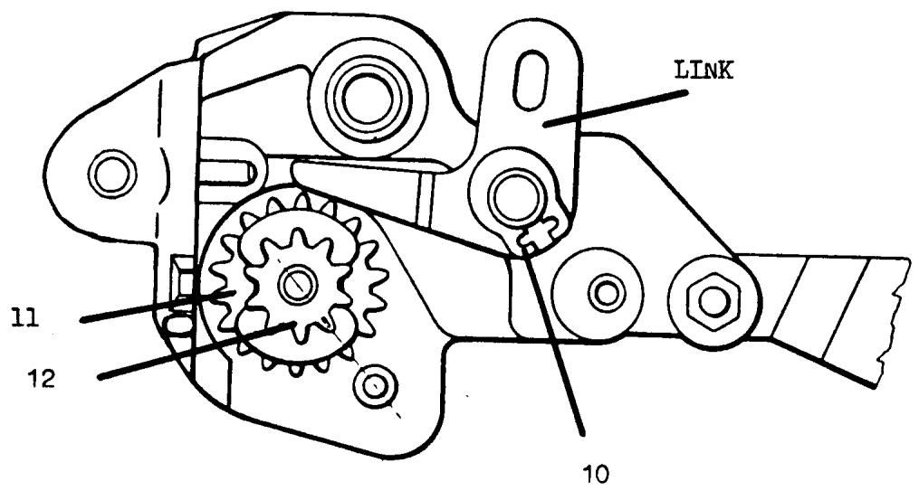
NOTES:
DISASSEMBLY CONTINUED
- Remove the Tru-Arc clip III. D (10) and take away the link. COMMENT
On later units the link's position is controlled by the Tru-Arc clip. The link position on earlier selectors is maintained by the mounting of the needle position support frame, the Tru-Arc clip was removed in step 4.
- Press out the elastic tumbler pin from the main shaft cog gear. Remove the starting position cog wheel III. D (11) and the main shaft gear III. D (12).
The pattern selector frame should be thoroughly cleaned in solvent to remove dried grease and pieces of any damaged cog gears. Clean and inspect each gear closely for damage.
COMMENT
For models 2000 through 30 series it is recommended that all gears be replaced. Beginning with 40 series a new method of construction for the gears was introduced. On the 40 series and later models only the defective gear need be replaced.
For models 2000 and 10 series machines the main shaft cog gear is grooved for installation of a concave spring washer and C-clip to attach the pattern selector color scale.
The starting position cog wheel for these models has only one slot for the intrical tab on the color scale which determines the correct position and drives the scale. The new style gears may be used; however, a change for the mounting of the pattern selector scale and knob is necessary.
For models 2000 the scale retention coil spring used on later models and the zigzag knob for the model 2000 is used in place of the original pattern selector knob.
ORDER SPARE PARTS
41 10 122 Coil spring
41 11 223 Knob (remove metal sleeve)
For the 10 series the color scale, retention spring, and pattern selector knob are replaced with the parts used on the 20 series.
ORDER SPARE PARTS
41 11 992 Scale
41 10 122 Spring
41 11 994 Knob
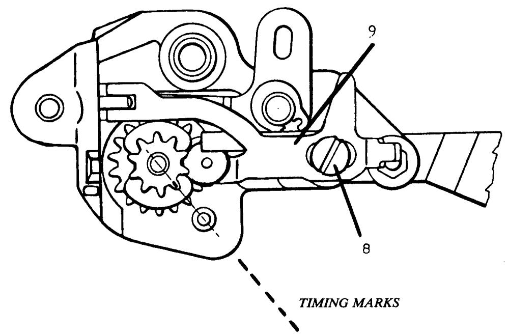
I11. "E"
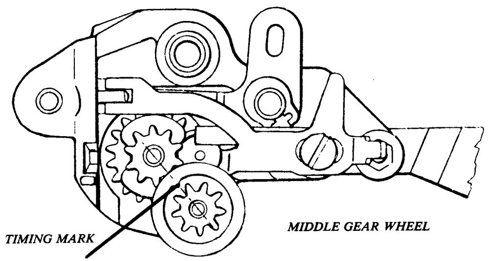
I11. "F"
ASSEMBLY
Closely examine each gear and identify the timing marks. The marks may be stamped or be visible as a mold mark. Check that the main shaft cog gear fits smoothly on the starting position cog wheel.
A small amount of lube (light grease) should be applied to each part when assembled. Order number 41 14 464 Molycote.
At each stage of installation the gears must be positioned with the timing marks aligned. Failure to maintain the required positions will result in the pattern selector not turning to all color settings.
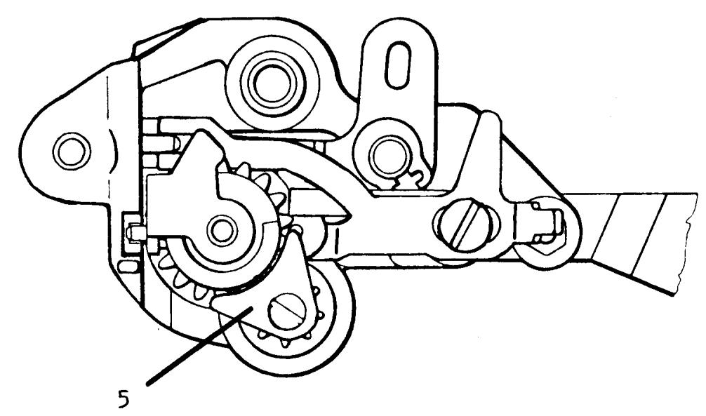
Ill. "G"
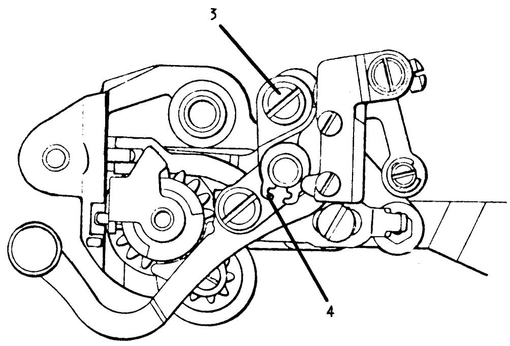
Ill. "H"
ASSEMBLY CONTINUED
- Hold the main gear with the timing mark aligned with the mark on the middle gear wheel; fit the fixed cam guide to the staged slotted area of the main gear. The cam guide must be positioned with the pin in the slot of the pattern selector frame and main gear.
Install the guide plate III. G (5) and secure the mounting screw.
COMMENT
The guide plate must not touch the main gear; hold the plate positioned as illustrated.
- Fit the needle position support frame to the pattern selector and install the left needle position eccentric screw III. H (3).
COMMENT
Before securing the lock nut to the setting screw ensure the concave spring steel washers are placed (outward) opposing each other.
On older models tighten one nut till the screw turns with firm resistance; hold the nut with a box spanner and tighten the second nut securely against the first. Recheck to determine the setting screw has enough resistance to hold adjustment.
- Install the Tru-Arc clip III. H (4) to the needle position support frame post. Check that the support frame pivots freely in its mounting.
COMMENT
Late style units have the Tru-Arc clip mounted behind the support frame; do not employ this assembly on older units or the alignment of the zigzag cam follower to the fixed cam will not be possible.
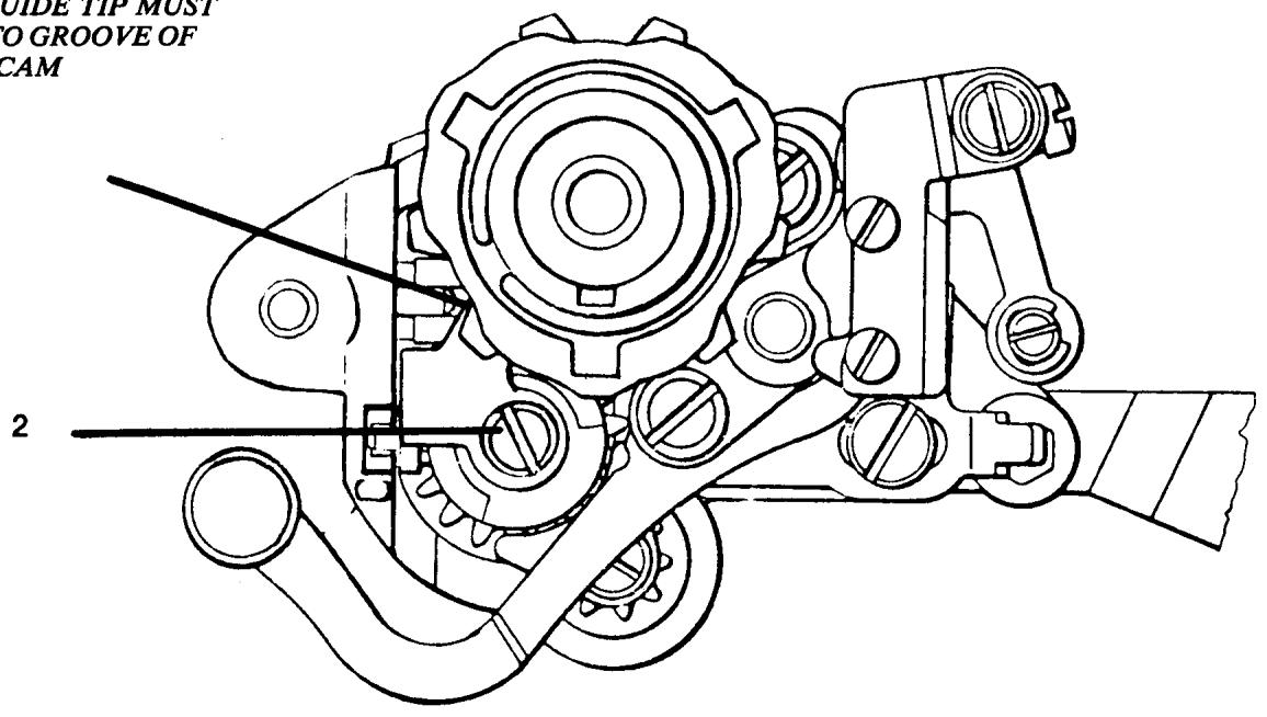
CAM GUIDE TIP MUST FIT INTO GROOVE OF FIXED CAM
III. "T"
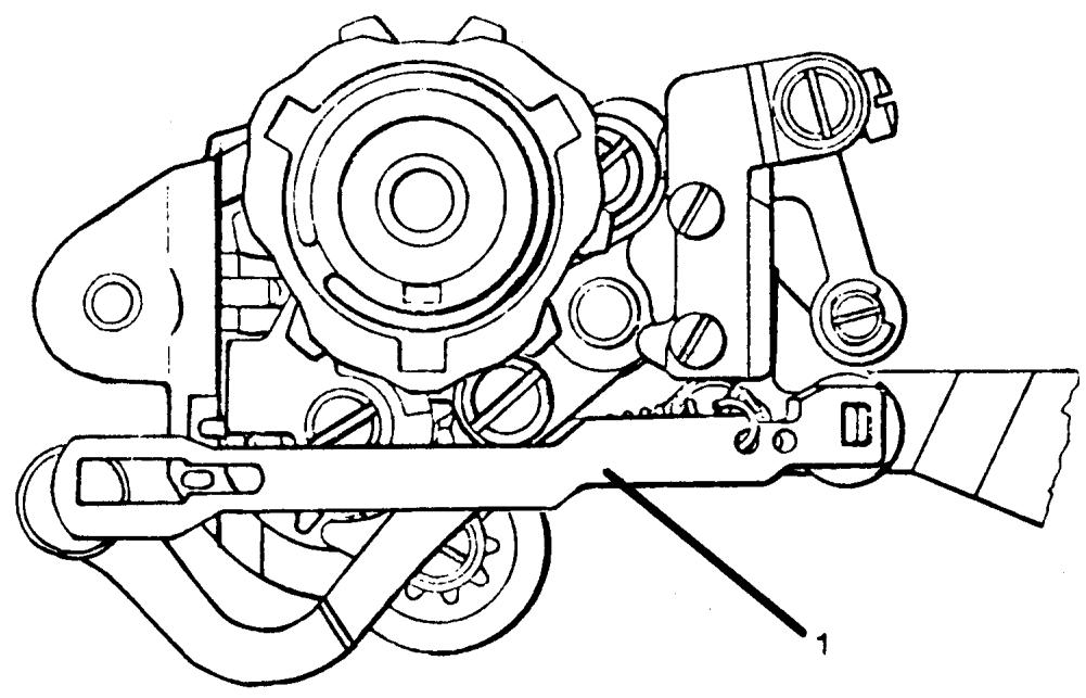
Ill. "J"
ASSEMBLY CONTINUED
-
Check that the fixed cam moves freely on the worm wheel. Install the worm wheel and fixed cam; be sure the cam guide tip is placed in the groove of the fixed cam. Install the long coil spring and make sure the fiber spacing washer is in place and secure the mounting screw III. I (2). CAUTION: Do not crossthread the cam guide; if damaged the cam guide must be replaced.
-
Install the connecting link and return spring III. J (1).
ASSEMBLY TEST
With the control knob test the unit for correct assembly. Turn the knob clockwise till it stops; this should be left needle position. Rotate the knob counterclockwise and determine the following lock positions.
- Center needle position
- Three step zigzag
- Color symbol Blue
- Color symbol Yellow
- Color symbol Red/Orange
- Color symbol Green/Purple
ASSEMBLY CONTINUED
- Models 2000 and 10 series machines have a position collar to secure the worm wheel. Turn the selector counter-clockwise to the left needle position. Mount the nylon friction washer and collar to allow 0.5mm end play of the worm wheel.
COMMENT
The fixed cam must not bind against the collar. Install additional nylon friction washers as required and maintain 0.5mm end play.
20 series machines employ a C-clip to mount the worm wheel; in this situation the 0.5mm end play needs to be checked.
With the introduction of the 30 series the worm wheel mounting is controlled by the pattern selector mounting screw.
COMMENT
The required 0.5mm clearance must be checked after installation to the machine.
40 series machines incorporated a one-piece nylon worm wheel. The worm wheel is longer and the nylon friction washer was omitted from installation.
When reinstalling the original one-piece nylon worm wheel do not install a friction washer or the worm wheel will be jammed.
If the later style fixed cam and metal worm wheel is to replace a one-piece unit, a friction washer will be necessary to maintain the required 0.5mm end play. Order number 41 10 592 Washer.
Should the pattern selector be damaged beyond repair and a complete new unit installed, the following details should be noted. Due to similar design, interchanging mechanisms from model to model is possible.
Pattern selectors from the 20 series are used for replacement on models 2000 and the 10 series.
Pattern selectors for model 6570 replace previous units on the 30 and 40 series.
COMMENT
Pattern selector installation models 2000 and 10 series: The zigzag cam follower tip is longer than the tip on the later 20 series. The old follower must be installed on the new unit.
30 and 40 series: The latest style pattern selectors for 6570 are used for replacement. The zigzag follower (slotted) plate from the old unit must be installed and the reverse automatic arem with connecting link.
REplacement OF THE BOBBIN SPINDLE
COMMENT I
There are two different bobbin spindles. The 40 11 882-01 is the older style with the straight cut gears. This is used on the 10 series machines and earlier models. The 41 13 919 is the newest style with helical cut gears. This bobbin spindle is used in reduction gears from the 20 series machines to present.
COMMENT II
The description for replacing the bobbin spindle will be for the latest series of machines, i.e., the 20 series to present. The same basic procedures are used for the earlier machines with a few exceptions which are easily figured out.
STEPS FOR REMOVAL
- Remove the reduction gear.
- Remove the two screws (32) and then remove the knob (31).
- Loosen the black screw (30) on the pulley (29). Then loosen the silver screw (33) on the same pulley. Looking directly at the bobbin spindle, notice there is a V notched out of the bobbin spindle. The silver screw has a case hardened point that is screwed into the notch. Remove the pulley (29).
NOTE
There should be a washer (28) in the pulley. It must be in the pulley for the reduction gear to run properly.
- Notice how the finger in the gear selector (24) fits into the groove in the hub (27). Remove the hub (27).
- Slide the bobbin spindle away from the cog wheel with pulley (19). Notice the position of the cog wheel with pulley to the bobbin spindle. Also, notice how the key in the bobbin spindle fits into a notch in the driver (18) which is in the cog wheel (19).
- Remove the bobbin spindle.
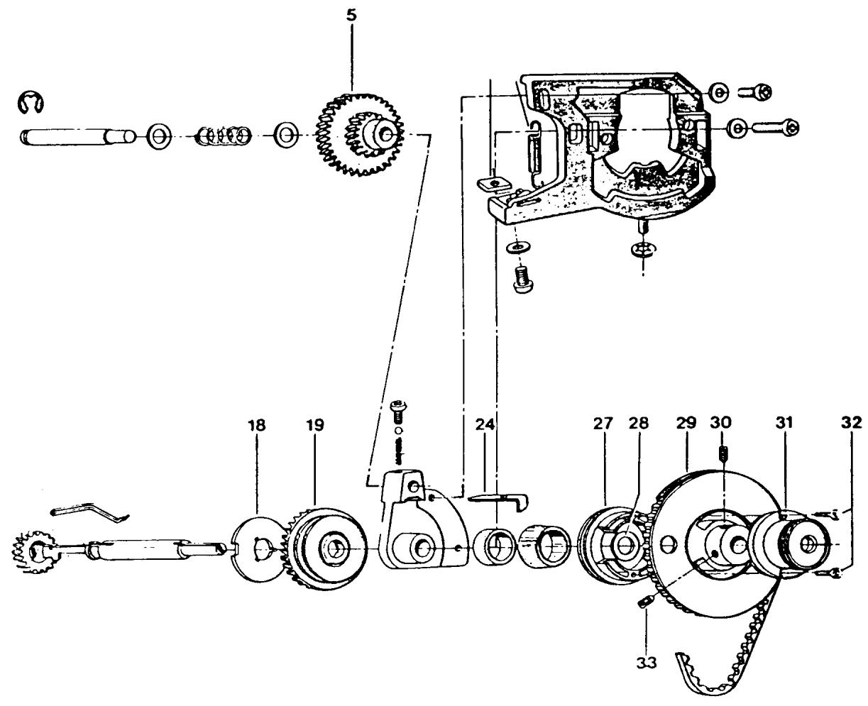
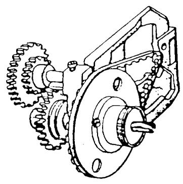
INSTALLATION OF BOBIN SPINDLE
STEPS FOR INSTALLATION
- Place the frame of the reduction gear in a position so the upper cog wheel (5) is facing to the left. Place the cog wheel (19), with the driver (18) facing outward, over the bearing in the reduction gear.
- Install the bobbin spindle. Make sure the key of the spindle goes into a slot in the driver.
- Install the hub (27) so that the finger in the gear selector (24) is in the groove of the hub.
- Install the washer (28) and pulley (29). Turn the pulley until the V notch in the bobbin spindle lines up with the silver screw. Make sure the bobbin spindle gear is flush with driver (18) of the cog wheel (19). Tighten the silver screw, then the black one.
NOTE
At this point check to see that there is no bind in the reduction gear. Also check to see that there is no end play in the bobbin spindle. If either one occurs, loosen the silver screw and make the correction.
- Install the knob (31) and tighten the 2 screws (32).
WIRING DIAGRAM
FLATBEDS
CLASSES 49E, 51, 51A, 51E, 71, 71E
MODELS 1310, 3310, 4310, 6310, 6320
- INTERFERENCE SUPPRESSORS (40 16 403)
Connect one lead, terminal point A, one lead terminal point B. Install second suppressor leads to terminal point F and terminal point E. - CONDENSER (40 16 524)
Connect one condenser lead to terminal point C, one lead, terminal point D. - DISCHARGE RESISTOR (40 16 392)
Connect one resistor lead, terminal point B, one lead, terminal point E. - LAMP
Connect one lead, terminal point B, one lead, terminal point E. - MOTOR
Connect one lead, terminal point E, one lead, terminal point D. - POWER SUPPLY CORD
Connect one lead, terminal point A, one lead, terminal point F.
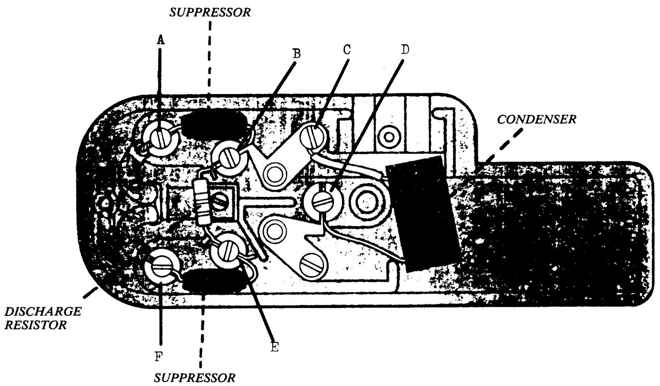
WIRING DIAGRAM
EARLY MODELS CL 19 - CL 20
1. POWER CROSSOVER LEAD
Install an insulated lead between terminal point B and terminal point H NOTE
Route lead under switch.
2. LAMP
Route lamp wires through opening J, connect one lead, terminal point A, one lead, terminal point G.
3. MOTOR
Connect one lead, terminal point C, one lead, terminal point F.
4. POWER SUPPLY CORD
Connect one lead, terminal point D, one lead, terminal point E.
NOTE
Secure cord restraint clamp; insure fiber insulation plate is installed or damage to the power supply cord will result.
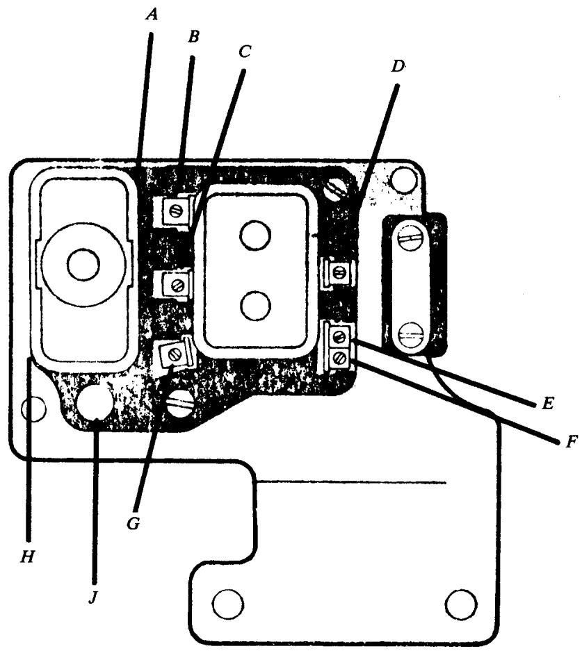
WIRING DIAGRAM
CLASSES 8, 19S, 19A, 21, 21A
1. LAMP
Route lamp wires through opening in motor mounting bracket; connect one lead, terminal point E, on lead, terminal point F.
2. MOTOR (4-wire)
The motor has four leads; two leads have ID bands, yellow and blue. Connect yellow band lead, terminal point E, blue band lead, terminal point D. Connect one brown lead, terminal point C, one brown lead, terminal point B.
3. POWER SUPPLY CORD
Connect one lead, terminal point A, one lead, terminal point B.
4. MOTOR (Late style 2-wire interchange)
Connect one lead, terminal point E, one lead, terminal point C. NOTE
All other connections remain the same.
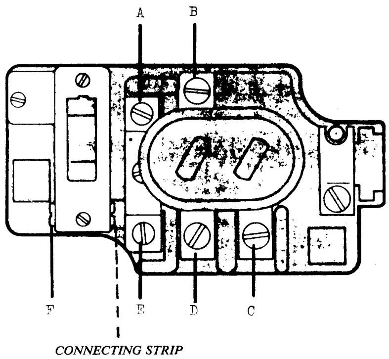
WIRING DIAGRAM
CLASSES 19E, 21E, 2000
MODELS 0210, 1010, 3010, 4010, 5010, 5210, 6010
- DISCHARGE RESISTOR (40 16 500)
Connect one resistor lead, terminal point G, one lead, terminal point F.
- CONNECTING STRIPS (40 16 511)
Install one connect strip between terminal points B and E, one strip between terminal points C and D.
- LAMP
Route lamp wires over top of terminal board. Connect one lead, terminal point B, one lead, terminal point C.
- MOTOR
The motor has four leads; two leads have ID bands, yellow and blue. Connect yellow band lead, terminal point G, blue band lead, terminal point F. Connect one black lead, terminal point B, one black lead, terminal point C.
NOTE
Route motor wires through opening A.
- POWER SUPPLY CORD
Connect one lead, terminal point E, one lead, terminal point D.
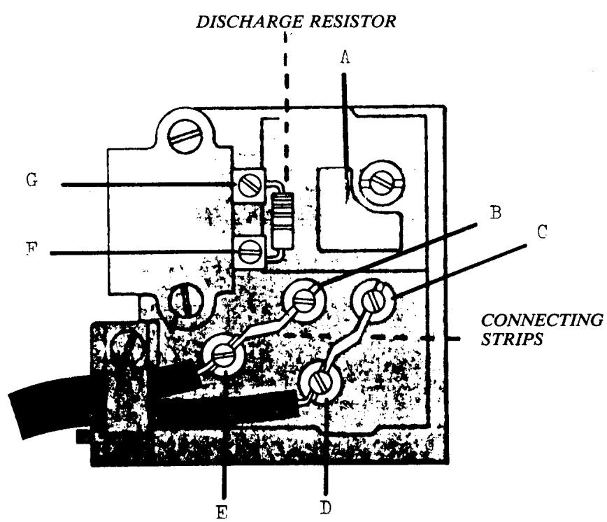
COMPLETE MOTOR EXCHANGE
Four-wire motors are no longer available; late style two-lead motors interchange.
Install components and rewire terminal board according to instructions for wiring diagram models 6020 and 6430.
WIRING DIAGRAM
MODELS 1020,3020,3220,4020,5220,6020 1030,3230,4030,5230,5430,5530,6030,6430
- DISCHARGE RESISTOR (40 16 500)
Connect one resistor lead, terminal point G, one lead, terminal point F.
- CONDenser (41 14 804) (not shown)
Connect one lead, terminal point G , one lead, terminal point F .
- INTERFERENCE SUPPRESSORS (40 16 514)
Connect one lead, terminal point E, terminal point B. Install second suppressor leads to terminal point D, and terminal point C.
- LAMP
Route lamp wires over top of terminal board. Connect one lead, terminal point B, one lead, terminal point C.
- MOTOR
Connect one lead, terminal point G , one lead terminal point C .
- POWER SUPPLY CORD
Connect one lead, terminal point E, one lead, terminal point D.
- COPPER WIRE
Connect one end to terminal point F . one end terminal point B.
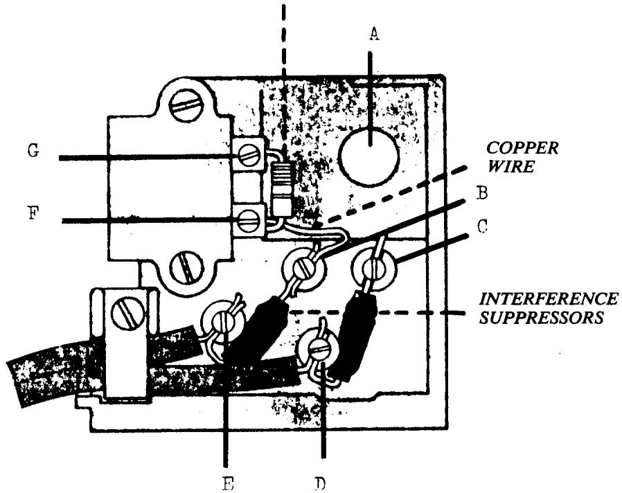
DISCHARGE RESISTOR
NOTE: CONDENSEN (40 16 795) NOT SHOWN
WIRING DIAGRAM
*MODELS
1040, 3240, 5540, 6440
1060, 3260, 5560, 6260, 6360, 6460
6170, 6270, 6370
- DISCHARGE RESISTOR (41 14 919)
Connect leads, terminal point A and point B.
- INTERFERENCE SUPPRESSORS (41 14 920)
Connect one suppressor between terminal point A and point E. Install second suppressor to terminal point B and point C.
- CONDENSEN (41 14 911)
Connect one lead, terminal point C, one lead, terminal point D.
- LAMP
Route lamp wires over top of terminal board. Connect one lead, terminal point E, one lead, terminal point C.
- MOTOR
Route motor wires through opening F. Connect one lead, terminal point E, one lead, terminal point D.
*This diagram does not include grounded (earthed) models.
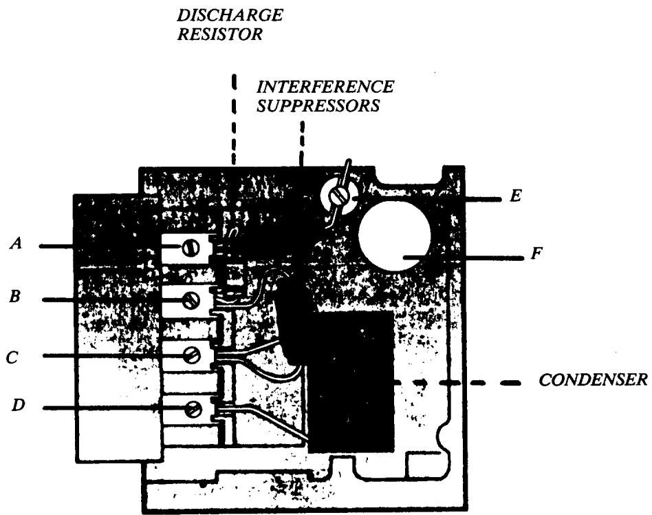
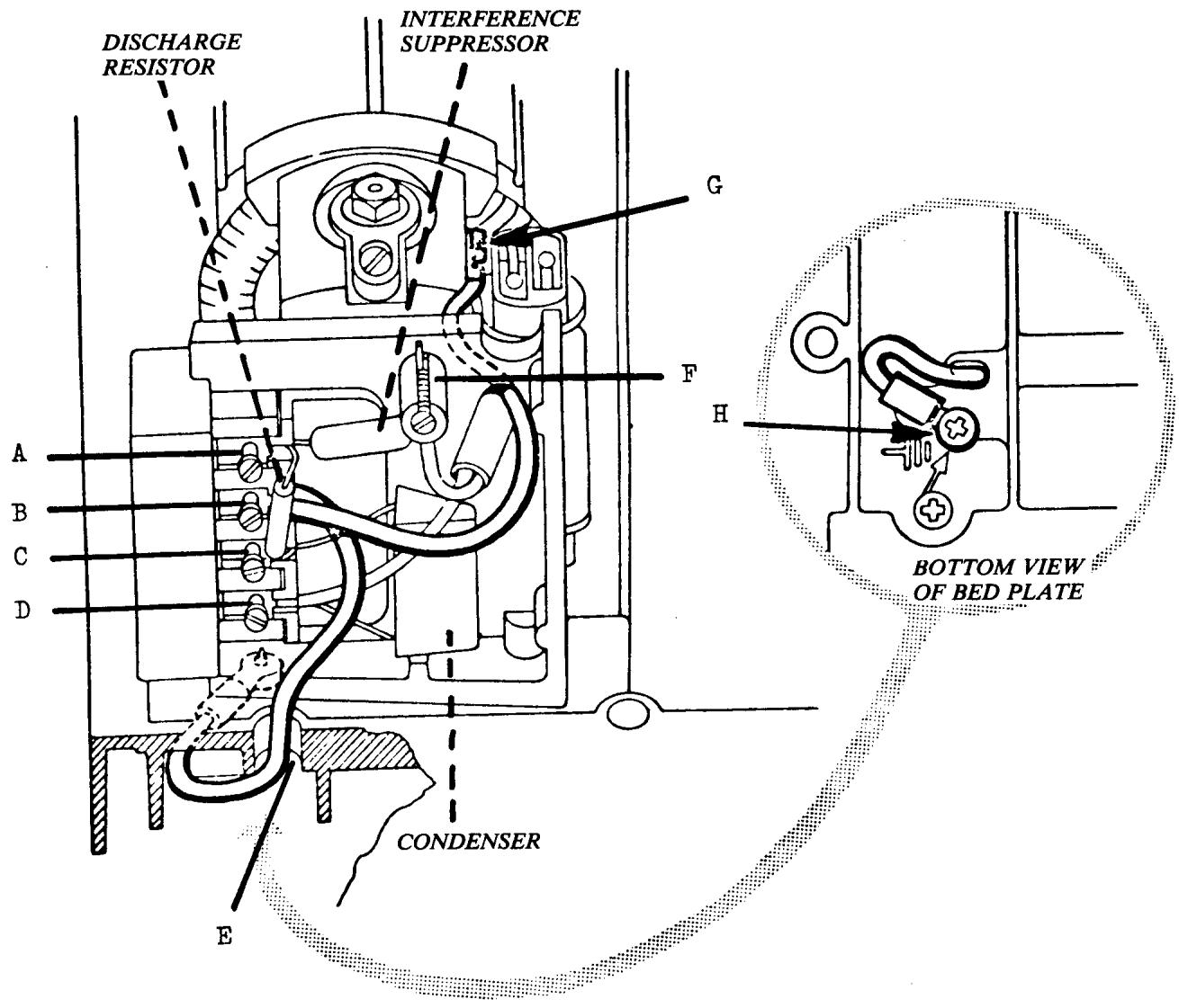
WIRING DIAGRAM
GROUNDED (EARTHED) MACHINES
MODELS 1040,3240,5540,6440
1060, 3260, 5560, 6260, 6360, 6460
6170, 6270, 6370
- DISCHARGE RESISTOR (41 14 919)
Connect leads, terminal point A and point C.
- INTERFERENCE SUPPRESSOR (41 14 920)
Connect one lead, terminal point C, one lead, terminal point F.
- CONDenser (41 14 911)
Connect one lead, terminal point C, one lead, terminal point D.
- LAMP
Route lamp wires over top of terminal board. Connect one lead, terminal point F, one lead, terminal point C.
- MOTOR
Connect one lead, terminal point F , one lead, terminal point D .
- GROUND WIRES (EARTH)
Install green (earth) wire with uninsulated connector to motor frame point G.
Connect other lead, terminal point B.
Route green (earth) wire with uninsulated connector to motor frame point G.
Connect other lead, terminal point B.
Route green (earth) wire with red insulator through opening in bed plate E.
Secure connector to bed plate, point H, with metal screw (23 23 294). Connect other lead, terminal point B.
CAUTION: The wiring instructions for grounded machines must not be employed on standard terminal boards.
These instructions apply to factory ground kits (49 36 000). For information regarding specific model application contact the nearest Viking Sewing Machines Co., Inc. Service Department.
FOOT CONTROL WIRING DIAGRAM
CLASSES 8, 19S, 19A, 19E, 21, 21A, 21E, 2000
MODELS 0210, 1010, 3010, 4010, 5010, 5210, 6010
- 185-OHM RESISTOR (40 16 476)
Connect one lead, terminal point A, one lead, terminal point C.
- INTERFERENCE SUPPRESSOR (40 16 506)
Connect lead with discharge resistor, terminal point C, connect other lead, terminal point B.
- CONDenser (40 16 507)
Connect one lead, terminal point A, one lead terminal point B.
- FOOT CONTROL CABLE
Connect one lead, terminal point A, one lead, terminal point B.
NOTE Ensure glass fiber insulation sleeves are installed on interference suppressor and condenser leads.