
FTXS-G ECO PERFORMANCE - Climatiseur mural DAIKIN - Notice d'utilisation et mode d'emploi gratuit
Retrouvez gratuitement la notice de l'appareil FTXS-G ECO PERFORMANCE DAIKIN au format PDF.

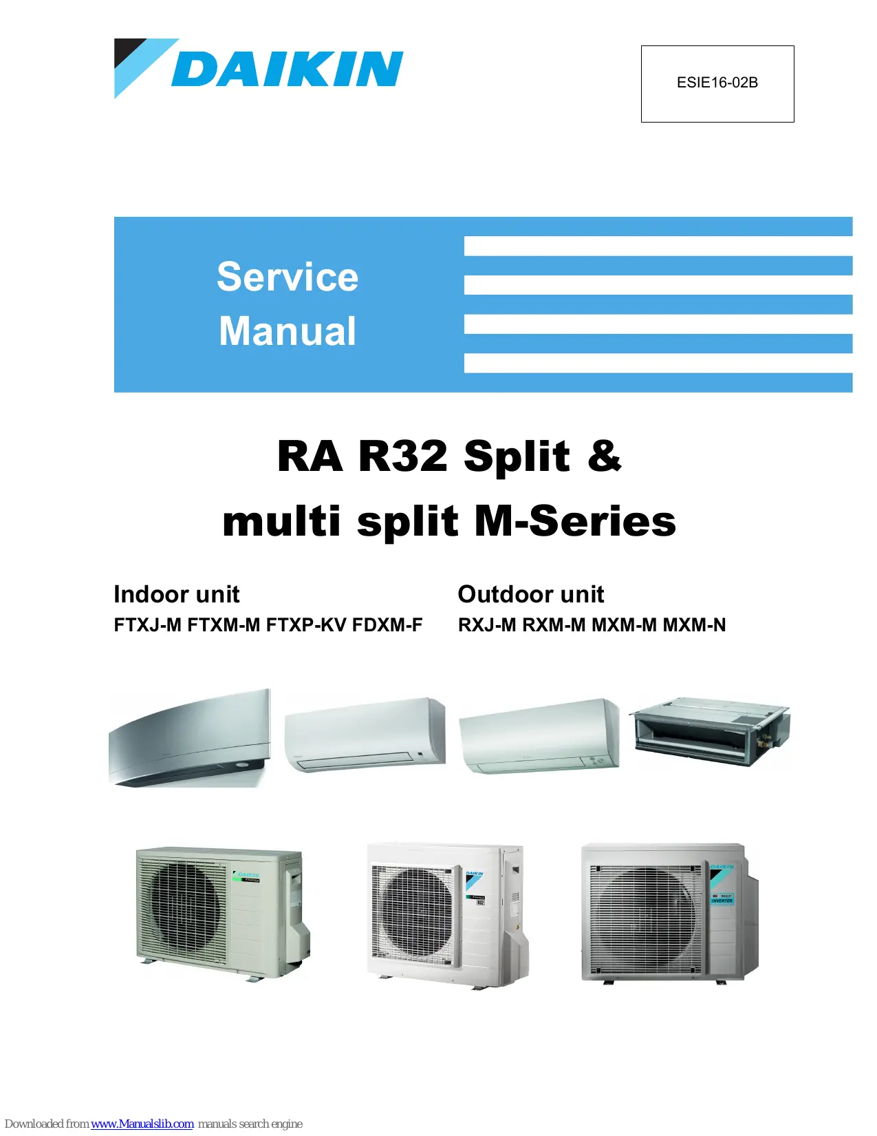

| Type de produit | Climatiseur mural split system |
| Marque | DAIKIN |
| Modèle | FTXS-G ECO PERFORMANCE |
| Fonctions principales | Refroidissement, chauffage, ventilation, déshumidification |
| Réfrigérant | R32 |
| Alimentation électrique | 230V ~ 50Hz, monophasé |
| Puissance frigorifique approximative | 2.5 kW à 3.5 kW (selon version) |
| Puissance calorifique approximative | 3.2 kW à 4.0 kW (selon version) |
| Classe énergétique (refroidissement) | A++ / A+++ |
| Niveau sonore intérieur (approximatif) | 19 – 39 dB(A) |
| Niveau sonore extérieur (approximatif) | 46 – 50 dB(A) |
| Dimensions de l'unité intérieure (approx.) | 795 x 287 x 218 mm (L x H x P) |
| Dimensions de l'unité extérieure (approx.) | 740 x 550 x 337 mm (L x H x P) |
| Poids de l'unité intérieure (approx.) | 9 kg |
| Poids de l'unité extérieure (approx.) | 33 kg |
| Longueur de tuyauterie max. | 20 m |
| Dénivelé max. | 12 m |
| Entretien et nettoyage | Nettoyer les filtres à air toutes les 2 semaines ; vérifier les échangeurs annuellement. |
| Sécurité | Arrêt automatique en cas de défaut ; protection contre les surtensions et les surchauffes. |
| Pièces détachées et réparabilité | Disponibles via réseau DAIKIN ; carte PCB, moteur ventilateur, thermistances, vanne 4 voies. |
| Informations générales | Notice d'utilisation de 114 pages incluant dépannage, maintenance et schémas. |
FOIRE AUX QUESTIONS - FTXS-G ECO PERFORMANCE DAIKIN
Questions des utilisateurs sur FTXS-G ECO PERFORMANCE DAIKIN
0 question sur cet appareil. Repondez a celles que vous connaissez ou posez la votre.
Poser une nouvelle question sur cet appareil
Téléchargez la notice de votre Climatiseur mural au format PDF gratuitement ! Retrouvez votre notice FTXS-G ECO PERFORMANCE - DAIKIN et reprennez votre appareil électronique en main. Sur cette page sont publiés tous les documents nécessaires à l'utilisation de votre appareil FTXS-G ECO PERFORMANCE de la marque DAIKIN.
MODE D'EMPLOI FTXS-G ECO PERFORMANCE DAIKIN
Service
Manual
RA R32 Split &
multi split M-Series
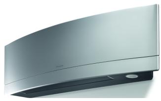
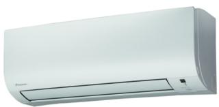
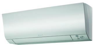
Indoor unit
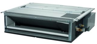
FTXJ-M FTXM-M FTXP-KV FDXM-F
Outdoor unit
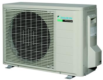
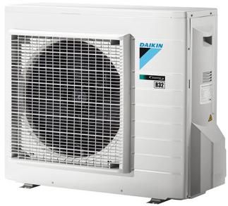
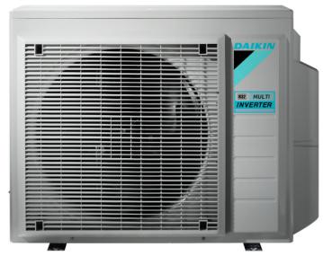
RXJ-M RXM-M MXM-M MXM-N
The present publication is drawn up by way of information only and does not constitute an offer binding upon Daikin Europe N.V.. Daikin Europe N.V. has compiled the content of this publication to the best of its knowledge. No express or implied warranty is given for the completeness, accuracy, reliability or fitness for particular purpose of its content and the products and services presented therein. Specifications are subject to change without prior notice. Daikin Europe N.V. explicitly rejects any liability for any direct or indirect damage, in the broadest sense, arising from or related to the use and/or interpretation of this publication. All content is copyrighted by Daikin Europe N.V..
Part 1. Introduction 9
1.1. Version log 9
1.2. Safety precautions 10
1.2.1. Meaning of symbols 10
1.2.2.Warnings 10
1.2.3.Cautions 12
1.2.4.Information 12
1.3. General operation 13
1.4.How to use 14
1.4.1. Interactive information flow 14
1.4.2. Parts of the book 15
1.4.2.1. The introduction chapter 15
1.4.2.2. The troubleshooting chapter 15
1.4.2.3. The repair chapter 15
1.4.2.4. The maintenance chapter 15
1.4.2.5. Appendices 15
1.4.3. Contact information 15
Part 2. Troubleshooting 17
2.1.Error codes check 17
2.1.1. Error codes via remote controller 17
2.1.1.1. General 17
2.1.1.2.How to reset error codes 17
2.1.1.3. History of error codes 17
2.1.2. Error codes via outdoor unit PCB 18
2.1.2.1. How to retrieve error codes 18
2.1.2.2.How to reset error codes 18
2.1.2.3. History of error codes 19
2.1.2.4. Content of retry 19
2.2.Error based troubleshooting 20
2.2.1. Indoor unit 21
2.2.1.1. "A1-00" - PCB abnormality 21
2.2.1.2. “A1-01” - PCB abnormality 21
2.2.1.3. "A5-00" - Freeze-up protection / Heating peak cut control 22
2.2.1.4. "A6-00" - Fan motor abnormality 22
2.2.1.5. "C4-00" - Liquid pipe thermistor for heat exchanger abnormality 23
2.2.1.6. "C7-00" - Front panel open/close fault 23
2.2.1.7. "C9-00" - Suction air thermistor abnormality 23
2.2.1.8.“UH-00” - Anti-icing function in other room(s) 24
2.2.2. Outdoor unit 25
2.2.2.1. "E1-00" - Outdoor unit PCB abnormality 25
2.2.2.2. "E3-00" - Discharge pressure abnormality 25
2.2.2.3. "E5-00" - Compressor motor lock or overheated 26
2.2.2.4. "E6-00" - Compressor motor lock 26
2.2.2.5. "E7-00" - Fan motor abnormality 27
2.2.2.6. "E8-00" - Compressor overcurrent detection 28
2.2.2.7. "EA-00" - 4-way valve abnormality 28
2.2.2.8. "F3-00" - Discharge pipe temperature abnormality 29
2.2.2.9. "F6-00" - High pressure abnormality or refrigerant overcharge 29
2.2.2.10. "H0-00" - Compressor sensor system abnormality 30
2.2.2.11. "H6-00" - Position detection sensor abnormality 30
2.2.2.12. "H8-00" - Compressor input (CT) system abnormality 31
2.2.2.13. "H9-00" - Outdoor air temperature thermistor abnormality 31
2.2.2.14. "J3-00" - Discharge pipe thermistor abnormality 32
2.2.2.15. "J5-00" - Suction pipe thermistor abnormality 32
2.2.2.16. "J6-00" - Outdoor heat exchanger thermistor abnormality 32
2.2.2.17. "J8-00" - Liquid pipe thermistor abnormality 33
2.2.2.18. "J9-00" - Gas pipe thermistor abnormality 33
2.2.2.19. "L1-00" - Outdoor main PCB abnormality 34
2.2.2.20. "L3-00" - Switch box temperature abnormality 34
2.2.2.21. "L4-00" - Inverter radiating fin temperature abnormality 35
2.2.2.22. "L5-00" - Inverter instantaneous overcurrent (AC output) 36
2.2.2.23. "P4-00" - Radiating fin temperature sensor abnormality 36
2.2.3. System 38
2.2.3.1. "U0-00" - Refrigerant shortage 38
2.2.3.2. "U2-00" - Power supply abnormality or instantaneous power failure 38
2.2.3.3. "U4-00" - Transmission abnormality between indoor unit and outdoor unit 39
2.2.3.4. "U7-00" - Transmission outdoor unit-outdoor unit abnormality 40
2.2.3.5. "UA-00" - Improper combination of indoor unit and outdoor unit 40
2.2.3.6.“UF-00”-Wiring and piping mismatch 41
2.2.4. Others 41
2.3. Symptom based troubleshooting 42
2.3.1. Indoor unit 42
2.3.2. Outdoor unit 42
2.3.3. System 42
2.3.4.Others 42
2.4. Component checklist 43
2.4.1. Indoor unit 44
2.4.1.1.Fan motor 44
2.4.2. Outdoor unit 45
2.4.2.1. 4-way valve 45
2.4.2.2. Compressor 47
2.4.2.3. Electronic expansion valve 49
2.4.2.4.Fan motor 51
2.4.2.5. High pressure sensor 52
2.4.2.6. Main PCB 53
2.4.2.7. Pressure sensor 54
2.4.2.8. Refrigerant thermistors 56
2.4.3. System 58
2.4.4. Others 58
2.5. Other capacity range 59
Part 3. Repair 61
3.1. Refrigerant repair procedures 61
3.1.1. Refrigerant piping handling 61
3.1.2. Recovery procedure 61
3.1.2.1. Outdoor unit casing 61
3.1.3. Refrigerant pump down 63
3.1.3.1. Small outdoor unit 63
3.1.3.2. Large outdoor unit 64
3.1.4. Piping repair procedures 64
3.2. Service tools 65
3.3. Unit specific repair procedures 66
3.3.1. Indoor unit 67
3.3.2. Outdoor unit 68
3.3.2.1. Basic removal 68
3.3.2.2.Replacing switch box 71
3.3.2.3.Replacing 4-way valve body 73
3.3.2.4. Replacing 4-way valve coil 75
3.3.2.5.Replacing compressor 76
3.3.2.6. Replacing DC fan motor assembly 79
3.3.2.7. Replacing expansion valve body 81
3.3.2.8.Replacing expansion valve motor 82
3.3.2.9. Replacing main PCB 84
3.3.2.10. Replacing propeller fan blade assembly 85
3.3.2.11. Replacing thermistors 87
3.3.2.12.Setting test mode for inverter checker 88
Part 4. Maintenance 89
4.1. Indoor unit 89
4.1.1. General maintenance 89
4.2. Outdoor unit 90
4.2.1. General maintenance outdoor unit 90
Part 5. Appendix 91
5.1. Field setting 93
5.1.1. Indoor unit 93
5.1.1.1. Indoor fan control during thermostat off in cooling 93
5.1.1.2. Brightness setting of multi-coloured lamp of the indoor unit 93
5.1.1.3. ON/OFF button on the indoor unit 93
5.1.2. Outdoor unit 94
5.1.2.1. Facility setting for outdoor split units 94
5.1.2.2. Multi split outdoor 94
5.1.3. Remote controller 96
5.2. Detailed information setting mode 97
5.2.1. Indoor unit 97
5.2.2. Outdoor unit 97
5.2.3. Remote controller 97
5.3.Wiring diagram 98
5.3.1. Indoor unit 98
5.3.2. Outdoor unit 99
5.3.2.1. 2MXM50M 99
5.3.2.2. 3MXM68M 99
5.3.2.3.4MXM-M 100
5.3.2.4. 5MXM-M 100
5.3.2.5.RXJ20-35M 101
5.3.2.6.RXJ50M 101
5.3.2.7.RXM20-35M 101
5.3.2.8.RXM42-50M 102
5.3.2.9.RXM60-71M 102
5.3.2.10.RXM71M 103
5.3.3. Field wiring 103
5.4.Piping diagram 104
5.4.1. Indoor unit 104
5.4.2. Outdoor unit 104
5.4.2.1. 2MXM40M 104
5.4.2.2.3MXM68M 105
5.4.2.3. 4MXM68M 105
5.4.2.4. 5MXM-M 106
5.4.2.5.RXJ20-35M 106
5.4.2.6.RXJ50M 107
5.4.2.7.RXM20-35M 107
5.4.2.8.RXM42-50M 108
5.4.2.9.RXM60 108
5.4.2.10.RXM71M 109
5.5. Component overview of unit 110
5.5.1. Indoor unit 110
5.5.2. Outdoor unit 110
5.6.Product specific information 111
5.6.1. Error codes 111
5.6.1.1. "E7-00" - Fan motor abnormality 111
5.6.1.2. "EA-00" - Malfunction of 4-way valve 111
5.6.1.3. "F3-00" - Discharge pipe temperature abnormality 111
5.6.1.4. "L3-00" - Switch box temperature abnormality 111
5.6.1.5. "L4-00" - Inverter radiating fin temperature abnormality 111
5.6.2. Component checklist 111
5.7. Switch box 111
5.7.1. Indoor unit 111
5.7.2. Outdoor unit 111
5.8. Field information report 112
Figure 2-1: Service display location 18
Figure 3-1: 1 service port at the stop valves 62
Figure 3-2: 3 service ports at the stop valves 63
Figure 3-3: Removing refrigerant connection cover 68
Figure 3-4: Removing the top plate 69
Figure 3-5: Removing the front plate 70
Figure 3-6: Removing the compressor sound insulation .70
Figure 3-7: Removing the switch box 72
Figure 3-8: Removing the 4-way valve 73
Figure 3-9: Removing the 4-way valve coil 75
Figure 3-10: Removing the compressor .77
Figure 3-11: Removing the DC fan motor assembly .80
Figure 3-12: Removing the expansion valve .81
Figure 3-13: Removing the expansion valve motor .82
Figure 3-14: Locking the expansion valve motor 83
Figure 3-15: Removing the main PCB .84
Figure 3-16: Removing the DC fan motor assembly .86
Figure 3-17: Replacing a thermistor .87
Figure 5-1: How to change fan OFF to ON when in cooling thermo off 93
Figure 5-2: Jumper settings 94
Figure 5-3: Service PC board wiring error check switch location 94
Figure 5-4: Dip switch location 95
Figure 5-5: S15 connector location 96
Figure 5-6: Jumper location 96
Figure 5-7: Wiring diagram - outdoor unit 2MXM50M .99
Figure 5-8: Wiring diagram - outdoor unit 3MXM68M 99
Figure 5-9: Wiring diagram - outdoor unit 4MXM-M 100
Figure 5-10: Wiring diagram - outdoor unit 2MXM50M 100
Figure 5-11: Wiring diagram - outdoor unit RXJ20-35M 101
Figure 5-12: Wiring diagram - outdoor unit RXJ50M 101
Figure 5-13: Wiring diagram - outdoor unit RXJ20-35M 101
Figure 5-14: Wiring diagram - outdoor unit RXM42-50M 102
Figure 5-15: Wiring diagram - outdoor unit RXM60-71M 102
Figure 5-16: Wiring diagram - outdoor unit RXM71M 103
Figure 5-17: Piping diagram - outdoor unit 2MXM40M 104
Figure 5-18: Piping diagram - outdoor unit 3MXM68M 105
Figure 5-19: Piping diagram - outdoor unit 4MXM68M 105
Figure 5-20: Piping diagram - outdoor unit 2MXM50M 106
Figure 5-21: Piping diagram - outdoor unit RXJ20-35M 106
Figure 5-22: Piping diagram - outdoor unit RXJ50M 107
Figure 5-23: Piping diagram - outdoor unit RXJ20-35M 107
Figure 5-24: Piping diagram - outdoor unit RXM42-50M 108
Figure 5-25: Piping diagram - outdoor unit RXM60 108
Figure 5-26: Piping diagram - outdoor unit RXM71M 109
Figure 5-27: Component overview - outdoor unit 110
Part 1. Introduction
This part contains the following chapters:
Version log. 9
Safety precautions. 10
General operation 13
How to use 14
1.1. Version log
| Version code | Description | Date |
| ESIE16-02A | Document release | 21/03/2017 |
| ESIE16-02B | Manual also applicable for MXM-N | 04/04/2017 |
1.2. Safety precautions
The precautions described in this document cover very important topics, follow them carefully.
All activities described in the service manual must be performed by an authorized person.
If you are not sure how to install, operate or service the unit, contact your dealer.
In accordance with the applicable legislation, it might be necessary to provide a logbook with the product containing at least: information on maintenance, repair work, results of tests, stand-by periods, ...
Also, at least, following information must be provided at an accessible place at the product:
- Instructions for shutting down the system in case of an emergency
Name and address of fire department, police and hospital
Name, address and day and night telephone numbers for obtaining service
In Europe, EN378 provides the necessary guidance for this logbook.
1.2.1. Meaning of symbols
| ! | WARNING Indicates a situation that could result in death or serious injury. |
| WARNING: RISK OF ELECTROCUTION Indicates a situation that could result in electrocution. | |
| WARNING: RISK OF BURNING Indicates a situation that could result in burning because of extreme hot or cold temperatures. | |
| WARNING: RISK OF EXPLOSION Indicates a situation that could result in explosion. | |
| WARNING: RISK OF POISONING Indicates a situation that could result in poisoning. | |
| WARNING: RISK OF FIRE Indicates a situation that could result in fire. | |
| CAUTION Indicates a situation that could result in equipment or property damage. | |
| INFORMATION Indicates useful tips or additional information. |
1.2.2.Warnings
| ! | WARNING Improper installation or attachment of equipment or accessories could result in electric shock, short-circuit, leaks, fire or other damage to the equipment. Only use accessories, optional equipment and spare parts made or approved by Dai-kin. |
| ! | WARNING Make sure installation, testing and applied materials comply with applicable legislation (on top of the instructions described in the Daikin documentation). |
| ! | WARNING Make sure the work site environment is clean and safe to work in. Beware of spilled fluids, like water, oil or other substances. Protect bystanders from injury and property from possible damage cause by service works. |
| ! | WARNING Wear adequate personal protective equipment (protective gloves, safety glasses,...) when installing, maintaining or servicing the system. |
| ! | WARNING Tear apart and throw away plastic packaging bags so that nobody, especially children, can play with them. Possible risk: suffocation. |
| ! | WARNING Do NOT touch the air inlet or aluminium fins of the unit. |
| ! | WARNING • Do NOT place any objects or equipment on top of the unit. • Do NOT sit, climb or stand on the unit. |
| ! | WARNING During tests, NEVER pressurize the product with a pressure higher than the maximum allowable pressure (as indicated on the nameplate of the unit). |
| ! | WARNING • Never mix different refrigerants or allow air to enter the refrigerant system. • Never charge recovered refrigerant from another unit. Use recovered refrigerant only on the same unit where it was recovered from, or have it recycled at a certified facility. |
| ! | WARNING: RISK OF FIRE • When reconnecting a connector to the PCB, do not apply force or damage the connector or the connector pins on the PCB. |
| ! | WARNING: RISK OF BURNING • Do NOT touch the refrigerant piping, water piping or internal parts during and immediately after operation. It could be too hot or too cold. Give it time to return to normal temperature. If you must touch it, wear protective gloves. • Do NOT touch any accidental leaking refrigerant. |
| ! | WARNING Always recover the refrigerants. Do NOT release them directly into the environment. Use a recovery pump to evacuate the installation. Take sufficient precautions in case of refrigerant leakage. If refrigerant gas leaks, ventilate the area immediately. Possible risks: • Excessive refrigerant concentrations in a closed room can lead to oxygen deficiency. • Toxic gas may be produced if refrigerant gas comes into contact with fire. Where applicable, pump down the system and close the service valve, before leaving the site if leak was not repaired, to avoid further leaking of the refrigerant. |
| ! | WARNING: RISK OF ELECTROCUTION • Turn OFF all power supply before removing the switch box cover, connecting electrical wiring or touching electrical parts. Where applicable, stop the equipment's operation first and allow (refrigerant) pressure to equalize, before turning OFF the power. Disconnect the power supply for more than 1 minute, and measure the voltage at the terminals of main circuit capacitors or electrical components before servicing. The voltage must be less than 50 V DC before you can touch electrical components. For the location of the terminals, refer to "Wiring diagram" on page 98. • Do NOT touch electrical components with wet hands. • Do NOT leave the unit unattended when the service cover is removed. • Protect electric components from getting wet while the service cover is opened. |

WARNING
Only use copper wires.
- All field wiring must be performed in accordance with the wiring diagram and installation manual supplied with the product.
- If the power cable and lead wires have scratches or deteriorated, be sure to replace them. Damaged cable and wires may cause an electrical shock, excessive heat generation or fire.
- Secure all terminal connections and provide proper routing for cables, both inside and outside the switchbox.
NEVER squeeze bundled cables and make sure they do not come in contact with the piping and sharp edges.
- Make sure no external pressure is applied to the terminal connections.
- Make sure to check the earth wiring. Do NOT earth the unit to a utility pipe, surge absorber, or telephone earth. Improper earth wiring may cause electrical shock.
Make sure to use a dedicated power circuit. NEVER use a power supply shared by another appliance.
Make sure to check the required fuses and/or circuit breakers before starting works.

WARNING
- After finishing the electrical work, confirm that each electrical component and terminal inside the electrical components box is connected securely.
Make sure all covers are closed before starting the unit again.
1.2.3. Cautions

CAUTION
Provide adequate measures to prevent that the unit can be used as a shelter by small animals. Small animals that make contact with electrical parts can cause malfunctions, smoke or fire.

CAUTION
Make sure water quality complies with EU directive 98/83 EC.
- Check the system for leaks after each repair/modification of the water side.
- Check drainage system(s) after repairs.
- Be careful when tilting units as water may leak.
1.2.4. Information

INFORMATION
Make sure refrigerant piping installation complies with applicable legislation. In Europe, EN378 is the applicable standard.

INFORMATION
Make sure the field piping and connections are not subjected to stress.
1.3. General operation
These split units are used for comfort cooling and are equipped with an inverter.
- The rotation speed rps (= rotation per second) of the inverter driven compressor, modulated by the inverter, can be varied according to the required capacity in the room.
- The compressor capacity step is changed in order to reach target compression ratio. The target compression ratio is calculated from deviation between actual and target condensation and evaporation temperature.
Tc (condensing temperature) is used in heating mode.
- Te (evaporation temperature) is used if any indoor unit operates in cooling mode.
- The evaporating temperature in the heat exchanger is controlled by the electronic expansion valve.
- When indoor unit is selecting heating mode, discharge gas is supplied by the outdoor unit to the indoor unit.
- When indoor unit is selecting cooling mode, liquid refrigerant is supplied by the outdoor unit to the indoor unit.
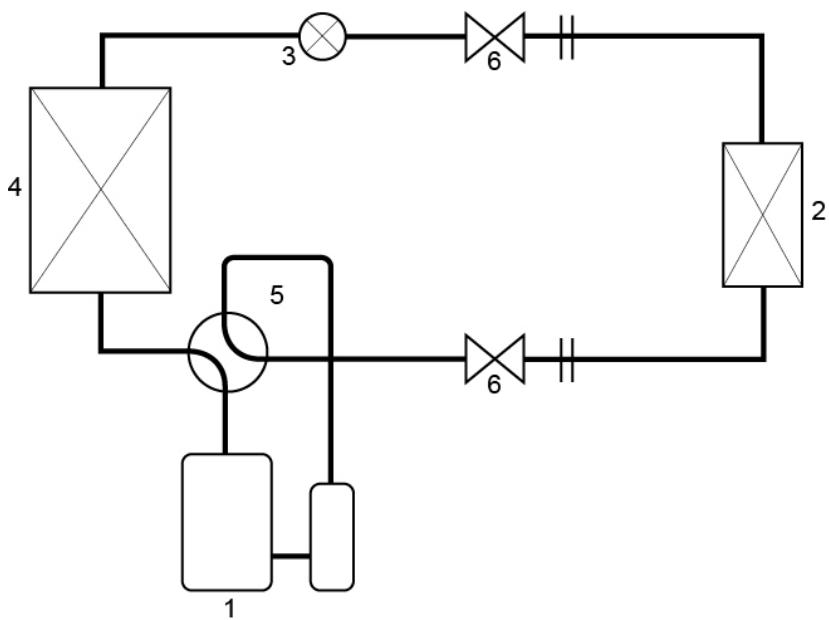
- Compressor
- Indoor heat exchanger
-
Expansion valve
-
Outdoor heat exchanger
- 4-way valve
- Stop valves
1.4. How to use
1.4.1. Interactive information flow
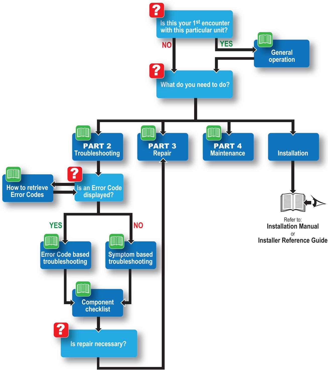
This Daikin product Service Manual is intended for professional use only. The actions described hereafter, are only to be performed by qualified and certified persons, taking into account the safety precautions mentioned in this manual and the local regulations as well.
By following the diagram below, the reader can find the relevant information related to his/her task. The digital (pdf) version of this book allows direct page access through all active links. When Adobe Acrobat Reader is used, the
1.4.2. Parts of the book
This Daikin product Service Manual is intended for professional use only. The actions described hereafter, are only to be performed by qualified and certified persons, taking into account the safety precautions mentioned in this manual and the local regulations as well.
As can be observed from the Table of Contents, this manual is split up into several chapters:
1.4.2.1. The introduction chapter
The chapter "Introduction" on page 9 includes the safety precautions, this topic and the general operation description of the product(s) this manual refers to.
1.4.2.2. The troubleshooting chapter
The chapter "Troubleshooting" on page 17 not only deals with the methods to recognize and resolve occurring error codes; it also describes the methods how to solve a problem that does not immediately trigger an error code. Such problems are referred to as 'symptom based'. Both the error code based and symptom based troubleshooting tables, indicate possible causes, the necessary checks and in case required, how to repair. The possible causes have been sorted to probability of occurrence and speed of execution.
1.4.2.3. The repair chapter
The chapter "Repair" on page 61 handles the removal and replacement of the major components in the product and discusses cleaning methods as well if applicable, such as for filters. Where applicable, refrigerant handling precautions are mentioned for certain actions; please consider these carefully for your own safety.
1.4.2.4. The maintenance chapter
The chapter "Maintenance" on page 89 of this manual describes the maintenance intervals and procedures to be performed on the product. Remember that a well maintained product, is a more reliable and efficient product.
1.4.2.5. Appendices
Finally, the service manual provides in chapter "Appendix" on page 91 valuable reference data such as piping/wiring diagrams, field settings overview and a checklist to be filled in when you need to escalate an issue to your dealer.
1.4.3. Contact information
This manual has been made with much care and effort. Use it in your daily jobs, as it has been made for you.
Despite our efforts, there is always a chance some cleric or other mistake has been made during the creation of this manual. We kindly ask you to send the found mistakes, or remarks for improvement, to the no-reply email address servicemanual@daikineurope.com.
Part 2. Troubleshooting
This part contains the following chapters:
Error codes check 17
Error based troubleshooting 20
Symptom based troubleshooting 42
Component checklist 43
Other capacity range 59
2.1. Error codes check
2.1.1. Error codes via remote controller
2.1.1.1. General
If operation stops due to malfunction, the remote controller's operation LED blinks, and malfunction code is displayed. (Even if stop operation is carried out, malfunction contents are displayed when inspection mode is entered.) The malfunction code enables you to tell what kind of malfunction caused operation to stop.
2.1.1.2. How to reset error codes
When the problem is solved, you can reset the error by pushing the ON/OFF-button.
2.1.1.3. History of error codes
Not applicable for this remote controller.
2.1.2. Error codes via outdoor unit PCB
2.1.2.1. How to retrieve error codes
Troubleshooting via the service display.
| GREEN | RED | GREEN | FLASHING: NORMAL | ON | FLASHING | ||||
| MICRO-COMPUTER NORMAL LED-A | MALFUNCTION DETECTION | RED | OFF: NORMAL | OFF | ANY STATUS | ||||
| LED1 | LED2 | LED3 | LED4 | LED5 | * MAY NOT BE APPLICABLE DEPENDING ON THE MODEL | ||||
| ● | ● | ● | ● | ● | normal -> check indoor unit | ||||
| ● | ● | high pressure protector activated or freeze-up in operating unit, or stand-by unit | |||||||
| ● | ● | ● | overload relay activated or high discharge pipe temperature | ||||||
| ● | ● | ● | faulty compressor start | ||||||
| ● | ● | ● | input overcurrent | ||||||
| ● | ● | ● | thermistor or ct abnormality | ||||||
| ● | ● | high temperature switchbox | |||||||
| ● | ● | ● | ● | high temperature at inverter circuit heatsink | |||||
| ● | ● | ● | ● | output overcurrent | |||||
| ● | ● | ● | refrigerant shortage | ||||||
| ● | ● | ● | low voltage to main circuit or over voltage to main circuit | ||||||
| ● | ● | ● | ● | reversing solenoid valve switching failure. * or high pressure switching failure | |||||
| ● | ● | faulty outdoor unit pcb | |||||||
| ● | fan motor fault | ||||||||
| ● | ● | ● | ● | wiring error check unfinished | |||||
| - | - | - | - | - | (Note 1) | ||||
| - | - | - | - | - | power supply fault | ||||
Note 1: Turn the power off and on again
Figure 2-1: Service display location
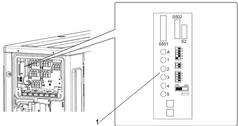
1. Service monitor LEDs
2.1.2.2. How to reset error codes
- When the problem is solved, perform a power reset
2.1.2.3. History of error codes
Not applicable
2.1.2.4. Content of retry
Not applicable
2.2. Error based troubleshooting
Overview of error codes:
Indoor unit. 21
"A1-00" - PCB abnormality. 21
"A1-01" - PCB abnormality. 21
"A5-00" - Freeze-up protection / Heating peak cut control. 22
"A6-00" - Fan motor abnormality 22
"C4-00" - Liquid pipe thermistor for heat exchanger abnormality 23
“C7-00” - Front panel open/close fault 23
"C9-00" - Suction air thermistor abnormality 23
"UH-00" - Anti-icing function in other room(s) 24
Outdoor unit 25
"E1-00" - Outdoor unit PCB abnormality 25
"E3-00" - Discharge pressure abnormality 25
"E5-00" - Compressor motor lock or overheated 26
"E6-00" - Compressor motor lock 26
"E7-00" - Fan motor abnormality. 27
"E8-00" - Compressor overcurrent detection 28
“EA-00” - 4-way valve abnormality. 28
"F3-00" - Discharge pipe temperature abnormality 29
"F6-00" - High pressure abnormality or refrigerant overcharge 29
"H0-00" - Compressor sensor system abnormality 30
"H6-00" - Position detection sensor abnormality 30
"H8-00" - Compressor input (CT) system abnormality 31
"H9-00" - Outdoor air temperature thermistor abnormality 31
"J3-00" - Discharge pipe thermistor abnormality 32
"J5-00" - Suction pipe thermistor abnormality 32
"J6-00" - Outdoor heat exchanger thermistor abnormality 32
"J8-00" - Liquid pipe thermistor abnormality 33
"J9-00" - Gas pipe thermistor abnormality 33
"L1-00" - Outdoor main PCB abnormality 34
"L3-00" - Switch box temperature abnormality 34
"L4-00" - Inverter radiating fin temperature abnormality 35
"L5-00" - Inverter instantaneous overcurrent (AC output) 36
"P4-00" - Radiating fin temperature sensor abnormality 36
System. 38
"U0-00" - Refrigerant shortage 38
"U2-00" - Power supply abnormality or instantaneous power failure 38
"U4-00" - Transmission abnormality between indoor unit and outdoor unit 39
"U7-00" - Transmission outdoor unit-outdoor unit abnormality 40
"UA-00" - Improper combination of indoor unit and outdoor unit 40
"UF-00" - Wiring and piping mismatch 41
Others 41
2.2.1. Indoor unit
2.2.1.1. "A1-00" - PCB abnormality
| Trigger | Effect | Reset |
| The system cannot set the internal settings | Unit will stop operating. | Power reset via outdoor unit. |
| Possible cause | Check | Corrective action |
| Wrong models interconnected | Check if unit combination is official.Refer to ‘Combination database’. | Install compatible models. |
| Faulty wiring. | Check the connection of all terminals by disconnecting and reconnecting all termi-nals. | Replace wire harness/terminal when con- nection is not OK. |
| Faulty or disturbance of the power supply (imbalance > 10%). Power drop. Short cir-cuit. | Check if the power supply is conform with regulations. No fluctuations in frequency. | Adjust power supply when required.Power reset via outdoor unit. |
| Faulty indoor PCB. | Check if error still occurs after turning off power and turning it back on again.Check if the indoor PCB receives power.Check if the HAP LED is blinking in regu-lar intervals.Check if the correct spare part is installed.Check the wiring to indoor PCB. | Adjust power to the indoor PCB.Replace indoor PCB when HAP LED is not blinking in regular intervals.Install correct spare part or update indoor PCB.Adjust wiring to indoor PCB when required. |
2.2.1.2. "A1-01" - PCB abnormality
| Trigger | Effect | Reset |
| The system cannot set the internal set-tings | Unit will stop operating. | Power reset via outdoor unit. |
| Possible cause | Check | Corrective action |
| Wrong models interconnected | Check if unit combination is official.Refer to ‘Combination database’. | Install compatible models. |
| Faulty wiring. | Check the connection of all terminals by disconnecting and reconnecting all termi-nals. | Replace wire harness/terminal when con- nection is not OK. |
| Faulty or disturbance of the power supply (imbalance > 10%). Power drop. Short cir-cuit. | Check if the power supply is conform with regulations. No fluctuations in frequency. | Adjust power supply when required.Power reset via outdoor unit. |
| Faulty indoor PCB. | Check if error still occurs after turning off power and turning it back on again.Check if the indoor PCB receives power.Check if the HAP LED is blinking in regu-lar intervals.Check if the correct spare part is installed.Check the wiring to indoor PCB. | Adjust power to the indoor PCB.Replace indoor PCB when HAP LED is not blinking in regular intervals.Install correct spare part or update indoor PCB.Adjust wiring to indoor PCB when required. |
2.2.1.3. "A5-00" - Freeze-up protection / Heating peak cut control
| Trigger | Effect | Reset |
| • during cooling operation, indoor heat exchanger temperature is below 0°C (freeze-up protection control). • during heating operation, indoor heat exchanger is above 65°C (heating peak-cut control). | Unit will stop operating. | Automatic reset when temperature is within range. |
| Possible cause | Check | Corrective action |
| Air short-circuit. | Check if the airflow around the unit is OK and there are no obstructions. | Remove obstruction. |
| Clogged air filter. | Check if the air filter is clogged. | Clean the air filter. |
| Dust accumulation on indoor heat exchanger. | Check if indoor heat exchanger is dirty/dusty. | Clean the indoor heat exchanger. |
| Faulty indoor heat exchanger thermistor. | Check indoor heat exchanger thermistor. | Replace indoor heat exchanger thermistor when required. |
| Faulty indoor PCB. | Check if error still occurs after turning off power and turning it back on again. Check if the indoor PCB receives power. Check if the HAP LED is blinking in regular intervals. Check if the correct spare part is installed. Check the wiring to indoor PCB. | Adjust power to the indoor PCB. Replace indoor PCB when HAP LED is not blinking in regular intervals. Install correct spare part or update indoor PCB. Adjust wiring to indoor PCB when required. |
2.2.1.4. "A6-00" - Fan motor abnormality
| Trigger | Effect | Reset |
| The rotation speed of the fan motor is not detected while the output voltage to the fan is at its maximum. | Unit will stop operating. | Power reset via outdoor unit. |
| Possible cause | Check | Corrective action |
| Faulty indoor PCB. | Check if error still occurs after turning off power and turning it back on again. Check if the indoor PCB receives power. Check if the HAP LED is blinking in regu- lar intervals. Check if the correct spare part is installed. Check the wiring to indoor PCB. | Adjust power to the indoor PCB. Replace indoor PCB when HAP LED is not blinking in regular intervals. Install correct spare part or update indoor PCB. Adjust wiring to indoor PCB when required. |
| Faulty indoor fan motor. | Check the fan motor. Check fan motor connections and wiring. | Replace fan motor when required. Adjust wiring when required. |
| Indoor fan motor locked. | Switch of the power. Turn fan manually. | Replace fan motor when the fan does not turn smoothly. |
More info:
| Check procedures | Replacing procedures |
| "Fan motor" on page 44 |
2.2.1.5. "C4-00" - Liquid pipe thermistor for heat exchanger abnormality
| Trigger | Effect | Reset |
| Thermistor input is > 4.96 V or < 0.04 V during compressor operation. | Unit will stop operating. | Power reset via outdoor unit. |
| Possible cause | Check | Corrective action |
| Faulty liquid pipe thermistor. | Check liquid pipe thermistor. | Replace liquid pipe thermistor when required. |
| Faulty indoor unit main PCB. | Check if error still occurs after turning off power and turning it back on again. Check if the indoor PCB receives power. Check if the HAP LED is blinking in regular intervals. Check if the correct spare part is installed. Check the wiring to indoor PCB. | Adjust the power to the indoor main PCB. Replace indoor main PCB when HAP LED is not blinking in regular intervals. |
More info:
| Check procedures | Replacing procedures |
| "Refrigerant thermistors" on page 56 |
2.2.1.6. "C7-00" - Front panel open/close fault
| Trigger | Effect | Reset |
| Shutter limit switch not activated or faulty. | Unit will stop operating when error occurs 2 times. | Power reset via outdoor unit. |
| Possible cause | Check | Corrective action |
| Foreign substance in the blow port. | Check blow port for foreign material. | Remove foreign material when required. |
| Faulty shutter limit switch. | Check the limit switch continuity. | Replace the limit switch when continuity is not good. |
| Faulty wire harness. | Check the wire harness wiring. Check the wire harness connection. | Reconnect wire harness when required. Perform a power reset, if shutter valve does not close after power reset, replace wire harness. |
| Faulty shutter motor. | Check if motor operates after opening the shutter and power reset. | Replace indoor unit main PCB when required. |
| Faulty shutter sealing. | Check if shutter goes back open automat-ically after closing. | Replace sealing material when required. |
| Shutter is deformed. | Check if the error is still active after clos-ing the shutter. | Replace shutter panel when required. |
2.2.1.7. "C9-00" - Suction air thermistor abnormality
| Trigger | Effect | Reset |
| Resistance value is out of range. T measured < -43.6°C or > 90°C. | Unit will stop operating. | Automatic reset when resistance is within range. |
| Possible cause | Check | Corrective action |
| Faulty suction air thermistor. | Check suction air thermistor. | Replace suction air thermistor when required. |
| Faulty indoor PCB. | Check if error still occurs after turning off power and turning it back on again. Check if the indoor PCB receives power. Check if the HAP LED is blinking in regular intervals. Check if the correct spare part is installed. Check the wiring to indoor PCB. | Adjust power to the indoor PCB. Replace indoor PCB when HAP LED is not blinking in regular intervals. Install correct spare part or update indoor PCB. Adjust wiring to indoor PCB when required. |
More info:
| Check procedures | Replacing procedures |
| "Refrigerant thermistors" on page 56 |
2.2.1.8. "UH-00" - Anti-icing function in other room(s)
| Trigger | Effect | Reset |
| A wrong connection is detected by check-ing the combination of the indoor and outdoor unit on the CPU | Operation halt due to freeze up prevention in other room/unspecified internal or externa voltages/mismatch indoor and outdoor units | Auto reset after freeze up prevention is finished. Unit cannot restart before mismatch is removed. |
| Possible cause | Check | Corrective action |
| Freeze up prevention in other room. | Indoor fan is not operating while the error is displayed. | See error A5. |
| Mismatch of outdoor-indoor units. | Verify connection on combination data-base. | Replace indoor units when required. |
| Unspecified voltages. | Check supply voltage. | Adjust when required. |
2.2.2. Outdoor unit
2.2.2.1. "E1-00" - Outdoor unit PCB abnormality
| Trigger | Effect | Reset |
| Outdoor main PCB detects that EEPROM is abnormal. | Unit will stop operating. | Manual reset via user interface. Power reset via outdoor unit. |
| Possible cause | Check | Corrective action |
| Faulty outdoor unit main PCB. | Check if the HAP LED is blinking in regu- lar intervals. Check if the correct spare part is installed. Check if the outdoor main PCB receives power. | Restore the power to the outdoor main PCB. Replace outdoor main PCB when HAP LED is not blinking in regular intervals. |
| Faulty capacity adapter on outdoor main PCB installed. | Check if the correct capacity adapter is used. | Replace capacity adapter when required. |
| External factor (e.g. electrical noise) (cause when error is reset after power reset, and error happens again after a while). | Check for source which could cause elec- trical interference. | |
| Faulty outdoor fan motor. | Check the fan motor. Check fan motor connections and wiring. | Replace fan motor when required. Adjust wiring when required. |
| Faulty or disturbance of the power supply (imbalance > 10%). Power drop. Short cir- cuit. | Check if the power supply is conform with regulations. No fluctuations in frequency. | Adjust power supply when required. Power reset via outdoor unit. |
2.2.2.2. "E3-00" - Discharge pressure abnormality
| Trigger | Effect | Reset |
| Discharge pressure above 4.15 MPa. | Unit will stop operating. | Automatic reset when high pressure drops below 3.2 MPa. |
| Possible cause | Check | Corrective action |
| Stop valve is closed. | Check stop valve. | Open stop valve when required. |
| Blocked heat exchangers. | Are the heat exchangers clean? | Clean heat exchangers. |
| Insufficient airflow. | Are the fans operating? | Repair fan. |
| Non condensables in refrigerant. | Check for non condensables in refriger-ant. | In case of suspicion of non condensables, recover, vacuum and recharge with virgin refrigerant. |
| Disconnected HPS wire harness terminal on the PCB. | Verify connection wire harness terminal on PCB. | Reconnect the terminal. |
| Disconnected HPS wire harness terminal on the HPS. | Verify connection wire harness terminal on HPS. | Reconnect the terminal(s). |
| Defective outdoor PCB. | Verify resistance of the wire harness ter-minal on the outdoor PCB. | If nearly 0 Ohm, replace outdoor PCB. |
| Broken high pressure sensor wire har-ness. | Verify resistance of the wire harness. | If resistance = infinity, replace wire har-ness. |
| Defective high pressure switch. | Check the resistance of the high pressure switch. | If resistance = infinity, replace high pres-sure switch. |
2.2.2.3. "E5-00" - Compressor motor lock or overheated
| Trigger | Effect | Reset |
| Compressor overload is detected. | Unit will stop operating. | Automatic reset if the unit runs for 60 seconds without error. |
| Possible cause | Check | Corrective action |
| Faulty discharge pipe thermistor. | Check discharge pipe thermistor. | Replace discharge pipe thermistor when required. |
| Faulty outdoor fan motor. | Check the fan motor. Check fan motor connections and wiring. | Replace fan motor when required. Adjust wiring when required. |
| Faulty overload protection. | Check the overload protection. Check the overload protection connec-tions and wiring. | Replace the overload protection when required. Adjust wiring when required. |
| Faulty expansion valve. | Check the expansion valve. | Replace the expansion valve body or motor when required. |
| Faulty 4-way valve. | Check the 4-way valve. | Replace the 4-way valve coil or body when required. |
| Faulty outdoor unit main PCB. | Check if the HAP LED is blinking in regu-lar intervals. Check if the correct spare part is installed. Check if the outdoor main PCB receives power. | Restore the power to the outdoor main PCB. Replace outdoor main PCB when HAP LED is not blinking in regular intervals. |
| Faulty power module = faulty outdoor inverter PCB. | Check outdoor inverter PCB. Check if the HAP LED is blinking in regu-lar intervals. Check if the correct spare part is installed. | Restore the power to the outdoor inverter PCB. Replace the outdoor inverter PCB when required. |
| Refrigerant shortage. | Check for refrigerant shortage. Refer to the nameplate for the correct charge. | Charge the correct refrigerant amount when required. |
| Humidity in refrigerant (ice formation in expansion valve). | Check for humidity in the refrigerant. | In case of suspicion of humidity, recover, vacuum and recharge with virgin refriger-ant. |
| Non condensables in refrigerant. | Check for non condensables in refriger-ant. | In case of suspicion of non condensables, recover, vacuum and recharge with virgin refrigerant. |
| Stop valve is closed. | Check stop valve. | Open stop valve when required. |
2.2.2.4. "E6-00" - Compressor motor lock
| Trigger | Effect | Reset |
| The motor rotor does not rotate when the compressor is energized. | Unit will not stop operating. | Automatic reset after a continuous run for about 10 min. |
| Unit will stop operating. | Manual reset via user interface. |
| Possible cause | Check | Corrective action |
| Faulty discharge thermistor. | Check the discharge thermistor. | Replace discharge thermistor when required. |
| Refrigerant shortage. | Check for refrigerant shortage. Refer to the nameplate for the correct charge. | Charge the correct refrigerant amount when required. |
| Humidity in refrigerant (ice formation in expansion valve). | Check for humidity in the refrigerant. | In case of suspicion of humidity, recover, vacuum and recharge with virgin refriger-ant. |
| Non condensables in refrigerant. | Check for non condensables in refriger-ant. | In case of suspicion of non condensables, recover, vacuum and recharge with virgin refrigerant. |
| Stop valve is closed. | Check stop valve. | Open stop valve when required. |
| Refrigerant circuit is clogged (HP - LP > 0,26 MPa). | Check for possible blockage (blockages can be checked by measuring the refriger-ant/pipe temperature. Sudden drop in temperature could indicate a blockage (remark: this is not valid for the expansion valve)). | Replace the blocked part. |
| Faulty compressor. | Check compressor. Check connections and wiring of the compressor. Check expansion valve (liquid back issue). Check the refrigerant charge. Refer to the nameplate for correct charge. | Replace compressor when required. Investigate reason of breakdown. Replace expansion valve when required. Fix possible leak. |
| Compressor turned off too fast. | Wait for guard timer. | |
| Faulty outdoor unit main PCB. | Check if the HAP LED is blinking in regu-lar intervals. Check if the correct spare part is installed. Check if the outdoor main PCB receives power. | Restore the power to the outdoor main PCB. Replace outdoor main PCB when HAP LED is not blinking in regular intervals. |
| Faulty outdoor inverter PCB. | Check outdoor inverter PCB. Check if the HAP LED is blinking in regu-lar intervals. Check if the correct spare part is installed. | Restore the power to the outdoor inverter PCB. Replace the outdoor inverter PCB when required. |
| Faulty 4-way valve. | Check the 4-way valve. | Replace the 4-way valve coil or body when required. |
| Faulty expansion valve. | Check the expansion valve. | Replace the expansion valve body or motor when required. |
2.2.2.5. "E7-00" - Fan motor abnormality
| Trigger | Effect | Reset |
| Fan does not start in about 15~30 sec-ons = fan motor lock.It can occur that E7-00 error is triggered even when the fan motor is running caused by a faulty hall signal. | Unit will not stop operating. | Automatic reset after a continuous run. |
| Unit will stop operating. | Manual reset via user interface. |
| Possible cause | Check | Corrective action |
| Faulty outdoor fan motor. | Check the fan motor. Check fan motor connections and wiring. | Replace fan motor when required. Adjust wiring when required. |
| Faulty outdoor inverter PCB. | Check outdoor inverter PCB. Check if the HAP LED is blinking in regu- lar intervals. Check if the correct spare part is installed. | Restore the power to the outdoor inverter PCB. Replace the outdoor inverter PCB when required. |
| Blown fuse. | Check the fuse on the outdoor unit PCB's. | Replace fuse when required. |
2.2.2.6. "E8-00" - Compressor overcurrent detection
| Trigger | Effect | Reset |
| When the compressor is running the current exceeds 9.25 A ~ 20 A (depending on the unit) for 2.5 seconds. | Unit will stop operating. | Manual reset via user interface. |
| Possible cause | Check | Corrective action |
| Outdoor temperature is out of operation range. | Check the outdoor temperature. | Wait until the temperature is within operation range. |
| Faulty compressor. | Check compressor. Check connections and wiring of the compressor. Check expansion valve (liquid back issue). Check the refrigerant charge. Refer to the nameplate for correct charge. | Replace compressor when required. Investigate reason of breakdown. Replace expansion valve when required. Fix possible leak. |
| Faulty power module. = Faulty inverter PCB. | Check outdoor inverter PCB. Check if the HAP LED is blinking in regular intervals. Check if the correct spare part is installed. | Restore the power to the outdoor inverter PCB. Replace the outdoor inverter PCB when required. |
| Faulty or disturbance of the power supply (imbalance > 10%). Power drop. Short circuit. | Check if the power supply is conform with regulations. No fluctuations in frequency. | Adjust power supply when required. Power reset via outdoor unit. |
2.2.2.7. "EA-00" - 4-way valve abnormality
| Trigger | Effect | Reset |
| The room thermistor / indoor heat exchanger are not functioning within operation range. | Unit will not stop operating. | Automatic reset when unit runs without error for 60 minutes. |
| Unit will stop operating. | Manual reset via user interface. |
| Possible cause | Check | Corrective action |
| Faulty 4-way valve coil. | Check 4-way valve coil. | Replace 4-way valve coil when required. |
| Faulty 4-way valve body, blocked. | Check 4-way valve body. | Replace 4-way valve body when required. |
| Faulty outdoor unit main PCB. | Check if the HAP LED is blinking in regu-lar intervals. Check if the correct spare part is installed. Check if the outdoor main PCB receives power. | Restore the power to the outdoor main PCB. Replace outdoor main PCB when HAP LED is not blinking in regular intervals. |
| Faulty room thermistor. | Check room thermistor. | Replace room thermistor when required. |
| Faulty indoor heat exchanger thermistor. | Check indoor heat exchanger thermistor. | Replace indoor heat exchanger thermistor when required. |
| Refrigerant shortage. | Check for refrigerant shortage. Refer to the nameplate for the correct charge. | Charge the correct refrigerant amount when required. |
| Humidity in refrigerant (ice formation in expansion valve). | Check for humidity in the refrigerant. | In case of suspicion of humidity, recover, vacuum and recharge with virgin refriger-ant. |
| Non condensables in refrigerant. | Check for non condensables in refriger-ant. | In case of suspicion of non condensables, recover, vacuum and recharge with virgin refrigerant. |
| Stop valve is closed. | Check stop valve. | Open stop valve when required. |
| Faulty stop valve. | Check the stop valve. | Replace the stop valve when required. |
2.2.2.8. "F3-00" - Discharge pipe temperature abnormality
| Trigger | Effect | Reset |
| Discharge temperature is too high: • If the discharge temperature detected is above A°C, 10 times within 200 min. • If within 200 min the discharge temperature detected is 10 times above B°C for 15 min. | Unit will not stop operating. | Automatic reset when temperature drops below C°C. |
| Unit will stop operating. | Manual reset via remote controller. |
| Possible cause | Check | Corrective action |
| Refrigerant shortage. | Check for refrigerant shortage. Refer to the nameplate for the correct charge. | Charge the correct refrigerant amount when required. |
| Humidity in refrigerant (ice formation in expansion valve). | Check for humidity in the refrigerant. | In case of suspicion of humidity, recover, vacuum and recharge with virgin refriger-ant. |
| Non condensables in refrigerant. | Check for non condensables in refriger-ant. | In case of suspicion of non condensables, recover, vacuum and recharge with virgin refrigerant. |
| Stop valve is closed. | Check if stop valve is open. | Open stop valve when required. |
| Faulty 4-way valve. | Check the 4-way valve. | Replace the 4-way valve coil or body when required. |
| Faulty expansion valve. | Check the expansion valve. | Replace the expansion valve body or motor when required. |
| Faulty outdoor unit main PCB. | Check if the HAP LED is blinking in regu-lar intervals. Check if the correct spare part is installed. Check if the outdoor main PCB receives power. | Restore the power to the outdoor main PCB. Replace outdoor main PCB when HAP LED is not blinking in regular intervals. |
| Faulty discharge thermistor. | Check discharge thermistor. | Replace discharge thermistor when required. |
| Faulty heat exchanger thermistor. | Check heat exchanger thermistor. | Replace heat exchanger thermistor when required. |
| Faulty outdoor temperature thermistor. | Check outdoor temperature thermistor. | Replace outdoor temperature thermistor when required. |
2.2.2.9. "F6-00" - High pressure abnormality or refrigerant overcharge
| Trigger | Effect | Reset |
| Outdoor heat exchanger thermistor meas-ures temperature > 60°C~65°C (depend-on model). | Unit will not stop operating. | Automatic reset when temperature drops below 50°C. |
| Possible cause | Check | Corrective action |
| Installation space is too small. | Check if the installation space is in line with regulations. | Adjust installation space. |
| Dirty outdoor heat exchanger. | Clean the outdoor heat exchanger. | |
| Faulty outdoor fan motor. | Check the fan motor. Check fan motor connections and wiring. | Replace fan motor when required. Adjust wiring when required. |
| Faulty stop valve. | Check the stop valve. | Replace the stop valve when required. |
| Faulty heat exchanger thermistor. | Check heat exchanger thermistor. | Replace heat exchanger thermistor when required. |
| Faulty expansion valve. | Check the expansion valve. | Replace the expansion valve body or motor when required. |
| Faulty outdoor unit main PCB. | Check if the HAP LED is blinking in regu- lar intervals. Check if the correct spare part is installed. Check if the outdoor main PCB receives power. | Restore the power to the outdoor main PCB. Replace outdoor main PCB when HAP LED is not blinking in regular intervals. |
2.2.2.10. "H0-00" - Compressor sensor system abnormality
| Trigger | Effect | Reset |
| DC voltage before compressor start-up is out of range (0.5~4.5 V). | Unit will stop operating. | Manual reset via user interface. |
| DC voltage before compressor start-up is below 50 V. | Unit will stop operating. | Manual reset via user interface. |
| Possible cause | Check | Corrective action |
| Faulty outdoor unit main PCB. | Check if the HAP LED is blinking in regu- lar intervals. Check if the correct spare part is installed. Check if the outdoor main PCB receives power. | Restore the power to the outdoor main PCB. Replace outdoor main PCB when HAP LED is not blinking in regular intervals. |
| Faulty outdoor inverter PCB. | Check outdoor inverter PCB. Check if the HAP LED is blinking in regu- lar intervals. Check if the correct spare part is installed. | Restore the power to the outdoor inverter PCB. Replace the outdoor inverter PCB when required. |
| Faulty connection or wiring of the PCB's. | Check the connections and the wiring of the PCB's. | Adjust connection or wiring when required. |
| Faulty or disturbance of the power supply (imbalance > 10%). Power drop. Short cir- cuit. | Check if the power supply is conform with regulations. No fluctuations in frequency. | Adjust power supply when required. Power reset via outdoor unit. |
2.2.2.11. "H6-00" - Position detection sensor abnormality
| Trigger | Effect | Reset |
| Compressor fails to start within 15 seconds after the compressor run command signal is sent. | Unit will not stop operating. | Automatic reset after a continuous run of 10 minutes. |
| Unit will stop operating if the warning occurs 8 times. | Manual reset via remote controller. |
| Possible cause | Check | Corrective action |
| Faulty compressor. | Check compressor. Check connections and wiring of the compressor. Check expansion valve (liquid back issue). Check the refrigerant charge. Refer to the nameplate for correct charge. | Replace compressor when required. Investigate reason of breakdown. Replace expansion valve when required. Fix possible leak. |
| Faulty outdoor unit main PCB. | Check if the HAP LED is blinking in regular intervals. Check if the correct spare part is installed. Check if the outdoor main PCB receives power. | Restore the power to the outdoor main PCB. Replace outdoor main PCB when HAP LED is not blinking in regular intervals. |
| Faulty outdoor inverter PCB. | Check outdoor inverter PCB. Check if the HAP LED is blinking in regu- lar intervals. Check if the correct spare part is installed. | Restore the power to the outdoor inverter PCB. Replace the outdoor inverter PCB when required. |
| Stop valve is closed. | Check stop valve. | Open stop valve when required. |
| Faulty or disturbance of the power supply (imbalance > 10%). Power drop. Short cir- cuit. | Check if the power supply is conform with regulations. No fluctuations in frequency. | Adjust power supply when required. Power reset via outdoor unit. |
2.2.2.12. "H8-00" - Compressor input (CT) system abnormality
| Trigger | Effect | Reset |
| DC voltage or DC current sensor abnormality based on the compressor running frequency and the input current. | Unit will not stop operating. | Automatic reset when compressor runs normally for 60 minutes. |
| Unit will stop operating if the warning occurs several times. | Manual reset via user interface. |
| Possible cause | Check | Corrective action |
| Faulty outdoor unit main PCB. | Check if the HAP LED is blinking in regu- lar intervals. Check if the correct spare part is installed. Check if the outdoor main PCB receives power. | Restore the power to the outdoor main PCB. Replace outdoor main PCB when HAP LED is not blinking in regular intervals. |
| Faulty power module. Input current or compressor current too low. Faulty outdoor inverter PCB. | Check outdoor inverter PCB. Check if the HAP LED is blinking in regu- lar intervals. Check if the correct spare part is installed. | Restore the power to the outdoor inverter PCB. Replace the outdoor inverter PCB when required. |
| Faulty compressor. | Check compressor. Check connections and wiring of the com- pressor. Check expansion valve (liquid back issue). Check the refrigerant charge. Refer to the nameplate for correct charge. | Replace compressor when required. Investigate reason of breakdown. Replace expansion valve when required. Fix possible leak. |
| Faulty reactor. | Check reactor. | Replace reactor when required. |
2.2.2.13. "H9-00" - Outdoor air temperature thermistor abnormality
| Trigger | Effect | Reset |
| Thermistor input voltage is > 4.96 V or < 0.04 V when power is on. | Unit will stop operating. | Manual reset via user interface. |
| Possible cause | Check | Corrective action |
| Faulty outdoor air temperature thermistor. | Check outdoor temperature thermistor. | Replace outdoor temperature thermistor when required. |
| Faulty outdoor unit main PCB. | Check if the HAP LED is blinking in regu- lar intervals. Check if the correct spare part is installed. Check if the outdoor main PCB receives power. | Restore the power to the outdoor main PCB. Replace outdoor main PCB when HAP LED is not blinking in regular intervals. |
2.2.2.14. "J3-00" - Discharge pipe thermistor abnormality
| Trigger | Effect | Reset |
| Thermistor input voltage is > 4.96 V or < 0.04 V when power is on. | Unit will stop operating. | Manual reset via user interface. |
| Discharge pipe temperature is lower than the heat exchanger temperature. |
| Possible cause | Check | Corrective action |
| Faulty discharge pipe thermistor. | Check discharge pipe thermistor. | Replace discharge pipe thermistor when required. |
| Faulty outdoor unit main PCB. | Check if the HAP LED is blinking in regu- lar intervals. Check if the correct spare part is installed. Check if the outdoor main PCB receives power. | Restore the power to the outdoor main PCB. Replace outdoor main PCB when HAP LED is not blinking in regular intervals. |
2.2.2.15. "J5-00" - Suction pipe thermistor abnormality
| Trigger | Effect | Reset |
| Suction pipe thermistor detects an abnormal value (open or short circuit). | Unit will stop operating. | Automatic reset. |
| Possible cause | Check | Corrective action |
| Faulty outdoor unit main PCB. | Check if the HAP LED is blinking in regu- lar intervals. Check if the correct spare part is installed. Check if the outdoor main PCB receives power. | Adjust the power to the outdoor main PCB. Replace outdoor main PCB when HAP LED is not blinking in regular intervals. |
| Faulty suction pipe thermistor. | Check suction pipe thermistor. | Replace suction pipe thermistor when required. |
| Faulty capacity adapter on outdoor PCB. | Check if the correct adapter is installed. Check if the correct spare part is installed. | Adjust capacity adapter when required. |
2.2.2.16. "J6-00" - Outdoor heat exchanger thermistor abnormality
| Trigger | Effect | Reset |
| Thermistor input voltage is > 4.96 V or < 0.04 V when power is on. | Unit will stop operating. | Manual reset via user interface. |
| Possible cause | Check | Corrective action |
| Faulty heat exchanger thermistor. | Check heat exchanger thermistor. | Replace heat exchanger thermistor when required. |
| Faulty outdoor unit main PCB. | Check if the HAP LED is blinking in regular intervals. Check if the correct spare part is installed. Check if the outdoor main PCB receives power. | Restore the power to the outdoor main PCB. Replace outdoor main PCB when HAP LED is not blinking in regular intervals. |
More info:
| Check procedures | Replacing procedures |
| "Refrigerant thermistors" on page 56 | "Replacing thermistors" on page 87 |
| "Main PCB" on page 53 | "Replacing main PCB" on page 84 |
2.2.2.17. "J8-00" - Liquid pipe thermistor abnormality
| Trigger | Effect | Reset |
| Liquid pipe thermistor detects an abnormal value (open or short circuit). | Unit will stop operating. | Automatic reset. |
| Possible cause | Check | Corrective action |
| Faulty outdoor unit main PCB. | Check if the HAP LED is blinking in regu- lar intervals. Check if the correct spare part is installed. Check if the outdoor main PCB receives power. | Adjust the power to the outdoor main PCB. Replace outdoor main PCB when HAP LED is not blinking in regular intervals. |
| Faulty liquid pipe thermistor. | Check liquid pipe thermistor. | Replace liquid pipe thermistor when required. |
| Faulty capacity adapter on outdoor PCB. | Check if the correct adapter is installed. Check if the correct spare part is installed. | Adjust capacity adapter when required. |
More info:
| Check procedures | Replacing procedures |
| "Main PCB" on page 53 | "Replacing main PCB" on page 84 |
| "Refrigerant thermistors" on page 56 | "Replacing thermistors" on page 87 |
2.2.2.18. "J9-00" - Gas pipe thermistor abnormality
| Trigger | Effect | Reset |
| Thermistor input voltage is > 4.96 V or < 0.04 V when power is on. | Unit will stop operating. | Manual reset via user interface. |
| Discharge pipe temperature is lower than the heat exchanger temperature. |
| Possible cause | Check | Corrective action |
| Faulty discharge pipe thermistor. | Check discharge pipe thermistor. | Replace discharge pipe thermistor when required. |
| Faulty outdoor unit main PCB. | Check if the HAP LED is blinking in regu-lar intervals. Check if the correct spare part is installed. Check if the outdoor main PCB receives power. | Restore the power to the outdoor main PCB. Replace outdoor main PCB when HAP LED is not blinking in regular intervals. |
More info:
| Check procedures | Replacing procedures |
| "Refrigerant thermistors" on page 56 | "Replacing thermistors" on page 87 |
| "Main PCB" on page 53 | "Replacing main PCB" on page 84 |
2.2.2.19. "L1-00" - Outdoor main PCB abnormality
| Trigger | Effect | Reset |
| Outdoor main PCB detects current/volt-age errors. | Unit will stop operating. | Manual reset via user interface. Power reset via outdoor unit. |
| Possible cause | Check | Corrective action |
| Blown fuse. | Check fuse on outdoor main PCB. | Replace fuse if blown. |
| Faulty outdoor unit main PCB. | Check if the HAP LED is blinking in regu- lar intervals. Check if the correct spare part is installed. Check if the outdoor main PCB receives power. | Adjust the power to the outdoor main PCB. Replace outdoor main PCB when HAP LED is not blinking in regular intervals. |
| Faulty outdoor inverter PCB. | Check outdoor inverter PCB. Check if the alive led is blinking in regular intervals. Check if the correct spare part is installed. | Adjust the power to the outdoor inverter PCB. Replace outdoor inverter PCB. |
| Faulty compressor. | Check compressor. Check connections and wiring of the com- pressor. Check expansion valve (liquid back issue). Check the refrigerant charge. Refer to the nameplate for correct charge. | Replace compressor when required. Investigate reason of breakdown. Replace expansion valve when required. Fix possible leak. |
| Faulty or disturbance of the power supply (imbalance > 10%). Power drop. Short cir- cuit. | Check if the power supply is conform with regulations. No fluctuations in frequency. | Adjust power supply when required. Power reset via outdoor unit. |
| Faulty outdoor fan motor. | Check the fan motor. Check fan motor connections and wiring. | Replace fan motor when required. Adjust wiring when required. |
| Faulty capacity adapter on outdoor PCB. | Check if the correct adapter is installed. Check if the correct spare part is installed. | Adjust capacity adapter when required. |
| External factory (e.g. electrical noise). (cause when error is reset after power reset, and error happens again after a while). | Check for source which could cause elec- trical interference. | Avoid electrical interference. |
More info:
| Check procedures | Replacing procedures |
| "Main PCB" on page 53 | "Replacing main PCB" on page 84 |
| "Compressor" on page 47 | "Replacing compressor" on page 76 |
| "Electronic expansion valve" on page 49 | "Replacing expansion valve body" on page 81 |
| "Fan motor" on page 51 | "Replacing DC fan motor assembly" on page 79 |
2.2.2.20. "L3-00" - Switch box temperature abnormality
| Trigger | Effect | Reset |
| Switch box temperature is too high when the compressor is off. | Unit will not stop operating. | Automatic reset when temperature drops. |
| Unit will stop operating. | Manual reset via remote controller. | |
| Possible cause | Check | Corrective action |
| Faulty outdoor inverter PCB. | Check outdoor inverter PCB. | Restore the power to the outdoor inverter PCB. |
| Faulty radiation fin thermistor. | Check if the HAP LED is blinking in regu- lar intervals. Check if the correct spare part is installed. | Replace the outdoor inverter PCB when required. |
| Faulty outdoor fan motor. | Check the fan motor. Check fan motor connections and wiring. | Replace fan motor when required. Adjust wiring when required. |
| Faulty or disturbance of the power supply (imbalance > 10%). Power drop. Short cir- cuit. | Check if the power supply is conform with regulations. No fluctuations in frequency. | Adjust power supply when required. Power reset via outdoor unit. |
| Outdoor heat exchanger is dirty. | Check outdoor heat exchanger. | Clean outdoor heat exchanger when required. |
More info:

INFORMATION
The Inverter PCB and Main PCB are 1 PCB in this unit.
| Check procedures | Replacing procedures |
| "Main PCB" on page 53 | "Replacing main PCB" on page 84 |
| "Fan motor" on page 51 | "Replacing DC fan motor assembly" on page 79 |
| "L3-00" – Switch box temperature abnormality" on page 111 | |
2.2.2.21. "L4-00" - Inverter radiating fin temperature abnormality
| Trigger | Effect | Reset |
| Radiation fin temperature rise is detected. | Unit will stop operating. | Automatic reset. |
| Power reset via outdoor unit. |
| Possible cause | Check | Corrective action |
| Faulty outdoor fan motor. | Check the fan motor. Check fan motor connections and wiring. | Replace fan motor when required. Adjust wiring when required. |
| Faulty or disturbance of the power supply (imbalance > 10%). Power drop. Short circuit. | Check if the power supply is conform with regulations. No fluctuations in frequency. | Adjust power supply when required. Power reset via outdoor unit. |
| Faulty radiating fin thermistor. | Check radiating fin thermistor. | Replace radiating fin thermistor when required. |
| Faulty outdoor unit PCB in which radiating fin thermistor is connected. | Check if the HAP LED is blinking in regu-lar intervals. Check if the correct spare part is installed. Check if the outdoor main PCB receives power. | Restore the power to the outdoor main PCB. Replace outdoor main PCB when HAP LED is not blinking in regular intervals. |
| Silicon grease is not applied properly on the radiation fin. | Check the silicon grease on the outdoor unit PCB. | Adjust silicon grease when required. |
More info:
| Check procedures | Replacing procedures |
| "Fan motor" on page 51 | "Replacing DC fan motor assembly" on page 79 |
| "Refrigerant thermistors" on page 56 | "Replacing thermistors" on page 87 |
| "Main PCB" on page 53 | "Replacing main PCB" on page 84 |
| "‘L4-00’ – Inverter radiating fin temperature abnormality" on page 111 | |
2.2.2.22. "L5-00" - Inverter instantaneous overcurrent (AC output)
| Trigger | Effect | Reset |
| An output overcurrent is detected by checking the current that flows in the inverter DC section. | Unit will stop operating. | Manual reset via user interface. |
| Possible cause | Check | Corrective action |
| Installation of the unit is not in line with specifications. | Check the installation specifications.Refer to the installation manual. | Adjust the installation when required. |
| Refrigerant shortage. | Check for refrigerant shortage. Refer to the nameplate for the correct charge. | Charge the correct refrigerant amount when required. |
| Humidity in refrigerator (ice formation in expansion valve). | Check for humidity in the refrigerant. | In case of suspicion of humidity, recover, vacuum and recharge with virgin refriger-ant. |
| Non condensables in refrigerant. | Check for non condensables in refriger-ant. | In case of suspicion of non condensables, recover, vacuum and recharge with virgin refrigerant. |
| Stop valve is closed. | Check stop valve. | Open stop valve when required. |
| Faulty power module = faulty outdoor inverter PCB. | Check outdoor inverter PCB.Check if the HAP LED is blinking in regu-lar intervals.Check if the correct spare part is installed. | Restore the power to the outdoor inverter PCB.Replace the outdoor inverter PCB when required. |
| Faulty compressor. | Check compressor.Check connections and wiring of the compressor.Check expansion valve (liquid back issue).Check the refrigerant charge. Refer to the nameplate for correct charge. | Replace compressor when required.Investigate reason of breakdown.Replace expansion valve when required.Fix possible leak. |
| Faulty or disturbance of the power supply (imbalance >10%). Power drop. Short cir-cuit. | Check if the power supply is conform with regulations. No fluctuations in frequency. | Adjust power supply when required.Power reset via outdoor unit. |
More info:

INFORMATION
The Inverter PCB and Main PCB are 1 PCB in this unit.
| Check procedures | Replacing procedures |
| "Main PCB" on page 53 | "Replacing main PCB" on page 84 |
| "Compressor" on page 47 | "Replacing compressor" on page 76 |
| "Electronic expansion valve" on page 49 | "Replacing expansion valve body" on page 81 |
2.2.2.23. “P4-00” – Radiating fin temperature sensor abnormality
| Trigger | Effect | Reset |
| Radiating fin thermistor input voltage is < 0.04 V or > 4.96 V when power is on. | Unit will stop operating. | Manual reset via user interface. |
| Possible cause | Check | Corrective action |
| Faulty radiating fin thermistor. | Check radiating fin thermistor. | Replace radiating fin thermistor when required. |
| Faulty outdoor unit PCB in which radiating fin thermistor is connected. | Check if the HAP LED is blinking in regu-lar intervals. Check if the correct spare part is installed. Check if the outdoor main PCB receives power. | Restore the power to the outdoor main PCB. Replace outdoor main PCB when HAP LED is not blinking in regular intervals. |
More info:
| Check procedures | Replacing procedures |
| "Refrigerant thermistors" on page 56 | "Replacing thermistors" on page 87 |
| "Main PCB" on page 53 | "Replacing main PCB" on page 84 |
2.2.3. System
2.2.3.1. "U0-00" - Refrigerant shortage
| Trigger | Effect | Reset |
| Refrigerant shortage detected. | Unit will stop operating. | Automatic reset. |
| Power reset via outdoor unit. |
| Possible cause | Check | Corrective action |
| Faulty air thermistor. | Check air thermistor. | Replace air thermistor when required. |
| Faulty discharge thermistor. | Check discharge thermistor. | Replace discharge thermistor when required. |
| Faulty outdoor heat exchanger thermistor. | Check outdoor heat exchanger thermistor. | Replace outdoor heat exchanger thermistor when required. |
| Stop valve is closed. | Check stop valve. | Open stop valve when required. |
| Refrigerant shortage. | Check for refrigerant shortage. Refer to the nameplate for the correct charge. | Charge the correct refrigerant amount when required. |
| Humidity in refrigerant (ice formation in expansion valve). | Check for humidity in the refrigerant. | In case of suspicion of humidity, recover, vacuum and recharge with virgin refrigerant. |
| Non condensables in refrigerant. | Check for non condensables in refrigerant. | In case of suspicion of non condensables, recover, vacuum and recharge with virgin refrigerant. |
| Faulty compressor. | Check compressor. Check connections and wiring of the compressor. Check expansion valve (liquid back issue). Check the refrigerant charge. Refer to the nameplate for the correct charge. | Replace compressor when required. Investigate reason of breakdown. Replace expansion valve when required. Fix possible leak. |
| Faulty expansion valve. | Check the expansion valve. | Replace the expansion valve body or motor when required. |
More info:
| Check procedures | Replacing procedures |
| "Refrigerant thermistors" on page 56 | |
| "Compressor" on page 47 | "Replacing compressor" on page 76 |
| "Electronic expansion valve" on page 49 | "Replacing expansion valve body" on page 81 "Replacing expansion valve motor" on page 82 |
| "Error codes" on page 111 | |
2.2.3.2. "U2-00" - Power supply abnormality or instantaneous power failure
| Trigger | Effect | Reset |
| There is no zero-cross detected in approximately 10 seconds (indoor unit PCB). | Unit will stop operating. | Power reset via outdoor unit. |
| Abnormal voltage drop (< 150-180 V) is detected by the DC voltage detection circuit. | Unit will stop operating. | Automatic restart after compressor stand-by of 3 minutes. |
| Abnormal voltage rise is detected by the over-voltage detection circuit. | Unit will stop operating. | Automatic restart after compressor stand-by of 3 minutes. |
| Possible cause | Check | Corrective action |
| Faulty or disturbance of the power supply (imbalance > 10%). Power drop. Short circuit. | Check if the power supply is conform with regulations. No fluctuations in frequency. | Adjust power supply when required. Power reset via outdoor unit. |
| Defective DC voltage detection circuit. | Check PCB with DC voltage detection circuit. | Replace PCB when required. |
| Defective over-voltage detection circuit. | Check PCB with over-voltage detection circuit. | Replace PCB when required. |
| Defective PAM control part. | Check PAM control part. | Replace PAM control part when required. |
| Faulty compressor. | Check compressor. Check connections and wiring of the compressor. Check expansion valve (liquid back issue). Check the refrigerant charge. Refer to the nameplate for correct charge. | Replace compressor when required. Investigate reason of breakdown. Replace expansion valve when required. Fix possible leak. |
| Faulty outdoor fan motor. | Check the fan motor. Check fan motor connections and wiring. | Replace fan motor when required. Adjust wiring when required. |
| Momentary drop of voltage. | - | Wait until compressor restarts. |
| Momentary power failure. | - | Wait until compressor restarts. |
| Faulty outdoor unit main PCB. | Check if the HAP LED is blinking in regular intervals. Check if the correct spare part is installed. Check if the outdoor main PCB receives power. | Restore the power to the outdoor main PCB. Replace outdoor main PCB when HAP LED is not blinking in regular intervals. |
| Faulty indoor unit main PCB. | Check if the HAP LED is blinking in regular intervals. Check if the correct spare part is installed. Check if the indoor main PCB receives power. | Restore the power to the indoor main PCB. Replace indoor main PCB when HAP LED is not blinking in regular intervals. |
More info:
| Check procedures | Replacing procedures |
| "Compressor" on page 47 | "Replacing compressor" on page 76 |
| "Electronic expansion valve" on page 49 | "Replacing expansion valve body" on page 81 |
| "Fan motor" on page 51 | "Replacing DC fan motor assembly" on page 79 |
| "Main PCB" on page 53 | "Replacing main PCB" on page 84 |
2.2.3.3. "U4-00" - Transmission abnormality between indoor unit and outdoor unit
| Trigger | Effect | Reset |
| Data sent from outdoor unit cannot be received normally, content of the send data is abnormal. | Unit will stop operating. | Power reset via outdoor unit. |
| Possible cause | Check | Corrective action |
| Faulty or disturbance of the power supply (imbalance > 10%). Power drop. Short circuit. | Check if the power supply is conform with regulations. No fluctuations in frequency. | Adjust power supply when required. Power reset via outdoor unit. |
| Wiring abnormality between indoor unit and outdoor unit. | Check wiring between indoor unit and outdoor unit. | Adjust wiring between indoor unit and outdoor unit when required. Replace wiring between indoor unit and outdoor unit when required. |
| Faulty outdoor unit main PCB. | Check if the HAP LED is blinking in regular intervals. Check if the correct spare part is installed. Check if the outdoor main PCB receives power. | Restore the power to the outdoor main PCB. Replace outdoor main PCB when HAP LED is not blinking in regular intervals. |
| Faulty outdoor fan motor. | Check the fan motor. Check fan motor connections and wiring. | Replace fan motor when required. Adjust wiring when required. |
| Faulty indoor unit main PCB. | Check if the HAP LED is blinking in regular intervals. Check if the correct spare part is installed. Check if the indoor main PCB receives power. | Restore the power to the indoor main PCB. Replace indoor main PCB when HAP LED is not blinking in regular intervals. |
More info:
| Check procedures | Replacing procedures |
| "Main PCB" on page 53 | "Replacing main PCB" on page 84 |
| "Fan motor" on page 51 | "Replacing DC fan motor assembly" on page 79 |
2.2.3.4. "U7-00" - Transmission outdoor unit-outdoor unit abnormality
| Trigger | Effect | Reset |
| Communication abnormality between out-door unit PCB's. | Unit will stop operating. | Manual reset via user interface. |
| Possible cause | Check | Corrective action |
| Faulty wiring between outdoor unit PCBs. | Check wiring between outdoor unit PCBs. | Adjust wiring between outdoor unit PCBs when required. |
| Faulty outdoor unit main PCB. | Check if the HAP LED is blinking in regu- lar intervals. Check if the correct spare part is installed. Check if the outdoor main PCB receives power. | Adjust the power to the outdoor main PCB. Replace outdoor main PCB when HAP LED is not blinking in regular intervals. |
| Faulty outdoor inverter PCB. | Check outdoor inverter PCB. Check if the alive led is blinking in regular intervals. Check if the correct spare part is installed. | Adjust the power to the outdoor inverter PCB. Replace outdoor inverter PCB. |
More info:
| Check procedures | Replacing procedures |
| "Replacing main PCB" on page 84 |
2.2.3.5. "UA-00" - Improper combination of indoor unit and outdoor unit
| Trigger | Effect | Reset |
| Signal transmission between indoor unit and outdoor unit abnormality. | Unit will stop operating. | Power reset via outdoor unit. |
| Possible cause | Check | Corrective action |
| Improper combination of indoor unit and outdoor unit. | Check combination. | Adjust installation when required. |
| Wiring abnormality between indoor unit and outdoor unit. | Check wiring between indoor unit and outdoor unit. | Adjust wiring between indoor unit and outdoor unit when required. Replace wiring between indoor unit and outdoor unit when required. |
| Faulty outdoor unit main PCB. | Check if the HAP LED is blinking in regular intervals. Check if the correct spare part is installed. Check if the outdoor main PCB receives power. | Restore the power to the outdoor main PCB. Replace outdoor main PCB when HAP LED is not blinking in regular intervals. |
| Faulty indoor unit main PCB. | Check if the HAP LED is blinking in regular intervals. Check if the correct spare part is installed. Check if the indoor main PCB receives power. | Restore the power to the indoor main PCB. Replace indoor main PCB when HAP LED is not blinking in regular intervals. |
More info:
| Check procedures | Replacing procedures |
| "Main PCB" on page 53 | "Replacing main PCB" on page 84 |
2.2.3.6. "UF-00" - Wiring and piping mismatch
| Trigger | Effect | Reset |
| When the interunit wiring between indoor and outdoor unit is incorrect. Piping abnormality. | Unit will stop operating. | Automatic reset. |
| Possible cause | Check | Corrective action |
| Faulty wiring between indoor and outdoor unit. | Check wiring between indoor and outdoor unit. | Correct wiring. |
| Refrigerant shortage (incorrect charge/leakage). | Check for refrigerant shortage. Perform a leak test. | If required, repair the leak and charge the correct amount of refrigerant. |
| Refrigerant circuit is clogged. | Check for possible blockage (Blockages can be checked by measuring the refriger-ant/pipe temperature. Sudden drop in temperature could indicate a blockage. (Remark: This is not valid for the expan-sion valve.)). |
More info:
| Check procedures | Replacing procedures |
| "Wiring diagram" on page 98 |
2.2.4. Others
Not applicable.
2.3. Symptom based troubleshooting
2.3.1. Indoor unit
Not available yet.
2.3.2. Outdoor unit
Not available yet.
2.3.3. System
Not applicable.
2.3.4. Others
Not applicable.
2.4. Component checklist
Overview of component checklists:
Indoor unit 44
Fan motor 44
Outdoor unit 45
4-way valve 45
Compressor 47
Electronic expansion valve 49
Fan motor 51
High pressure sensor 52
Main PCB 53
Pressure sensor 54
Refrigerant thermistors 56
System 58
Others 58
2.4.1. Indoor unit
2.4.1.1. Fan motor
| Technical specification | Description | ||
| The motor has a single connector for DC power and the rotation counter feed back from the integrated pulse generator (4 pulses/revolution). | The fan motor runs on a fixed speed to supply the required air flow rate. | ||
| Location | |||
| Piping diagram | Wiring diagram | Switch box | Component overview of unit |
| See "Indoor unit" on page 104. | See "Indoor unit" on page 98. | Not applicable. | Not applicable. |
| Check procedure | |||
| Mechanical check | |||
PRELIMINARY ACTIONS
- Switch off the Daikin unit via the user interface.
- Switch off the Daikin unit with the field supplied circuit breaker.
- Remove casing when required.
PROCEDURE
- Check the state of the rotor, replace the rotor if damaged, deformed, cracked or broken.
- Check the motor shaft bearing friction, only perform electrical check if motor runs with low shaft bearing friction. Replace fan motor if friction is abnormal.
Electrical check
PRELIMINARY ACTIONS
- Switch off the Daikin unit via the user interface.
- Switch off the Daikin unit with the field supplied circuit breaker.
- Remove casing when required.
PROCEDURE
- Check fuse on indoor PCB, replace if blown.

WARNING: RISK OF FIRE
When reconnecting a connector to the PCB, do not apply force, as this may damage the connector or connector pins of the PCB.
- Check if fan motor connector is plugged into PCB.
- Power the Daikin unit.
- Check power supply, the measured voltage must be 198 - 240 VAC, if not replace indoor PCB.
2.4.2. Outdoor unit
2.4.2.1. 4-way valve
| Technical specification | Description | ||
| - | The 4-way valve directs the super heated refrigerant discharged from the compressor to the indoor heat exchanger in case of heating operation or to the outdoor heat exchanger in case of defrost-ing and cooling operation. | ||
| Location | |||
| Piping diagram | Wiring diagram | Switch box | Component overview of unit |
| See "Outdoor unit" on page 104. | See "Outdoor unit" on page 99. | See "Outdoor unit" on page 111. | See "Outdoor unit" on page 110. |
| Check procedure | |||
| Mechanical check | |||
PRELIMINARY ACTIONS
- Switch off the Daikin unit via the user interface.
- Switch off the Daikin unit with the field supplied circuit breaker.
- Remove plate work when required.
PROCEDURE
- Loosen the screw and remove the coil from the 4-way valve (refer to "Replacing 4-way valve coil" on page 75).

WARNING: RISK OF FIRE
When reconnecting a connector to the PCB, do not apply force, as this may damage the connector or connector pins of the PCB.
- Unplug 4-way valve connector from applicable PCB, see table "Component checklist" on page 111.
- Switch on the Daikin unit via the user interface, start cooling/defrost operation.
If the temperature after the heat exchanger drops, proceed with next step.
If the temperature after the heat exchanger rises, the 4-way valve is stuck in heating position, replace the 4-way valve body (refer to "Replacing 4-way valve body" on page 73).
If the temperature after the heat exchanger does not rise, check the refrigerant pressure by connecting a manifold to one of the service ports.
- If no pressure is measured, perform a pressure test and fix any leaks.
- If pressure is measured, the 4-way valve is stuck in the middle, confirm by determining the position of the 4-way valve as described below and replace the 4-way valve (refer to "Replacing 4-way valve body" on page 73).

CAUTION - RISK OF LIQUID ENTERING THE COMPRESSOR
To prevent damage to the compressor the step below must only be done once.
- While listening to the 4-way valve, place a round permanent magnet on the core of the solenoid valve. If you do not hear the 4-way valve switching, it must be replaced (refer to "Replacing 4-way valve body" on page 73).
Electrical check
PRELIMINARY ACTIONS
-
Switch off Daikin unit via the user interface.
-
Switch off Daikin unit with the field supplied circuit breaker.
- Remove plate work when required.
PROCEDURE
- Switch on the Daikin unit, start heating operation.

WARNING: RISK OF FIRE
When reconnecting a connector to the PCB, do not apply force, as this may damage the connector or connector pins of the PCB.
-
Measure the voltage on 4-way valve connector: pin 1-3, see table "Component checklist" on page 111. If the measured voltage does not range 220-240 VAC during switching / 15 VAC after switching, unplug 4-way valve connector from PCB and measure the voltage directly on the PCB: pin 1-3 of 4-way valve connection.
-
If the voltage, measured directly on the PCB does not range 220-240 VAC during switching / 15 VAC after switching, replace main PCB.
If the voltage, measured directly on the PCB does range 220-240 VAC during switching / 15 VAC after switching, replace the 4-way valve coil (refer to "Replacing 4-way valve coil" on page 75).

WARNING: RISK OF FIRE
When reconnecting a connector to the PCB, do not apply force, as this may damage the connector or connector pins of the PCB.
- Unplug 4-way valve connector from PCB and measure the resistance of the 4-way valve coil. If the measured resistance does not range 1000 - 2000 Ω , replace the 4-way valve coil (refer to "Replacing 4-way valve coil" on page 75).
- Switch on the Daikin unit, start cooling/defrost operation.
If the temperature after the plate type heat exchanger rises, the control of the 4-way valve is wrong. Replace main PCB.
Determine the position of the 4-way valve
- Switch off Daikin unit via the user interface.
- Switch off Daikin unit with the field supplied circuit breaker.
- Slide a magnet over the front and the rear of the 4-way valve body and sense the attraction of the magnet to determine the valve position.
- If the magnet is attracted in positions A,A' or B,B', the 4-way valve is OK; if the magnet is attracted in positions C,C' the 4-way valve must be replaced (refer to "Replacing 4-way valve body" on page 73).
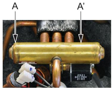
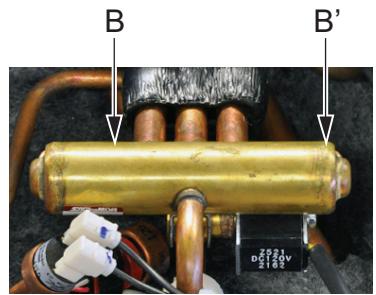
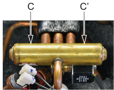
2.4.2.2. Compressor
| Technical specification | Description | ||
| Type: inverter driven, swing double swing. | The compressor compresses the refrigerant in the refrigerant circuit. | ||
| Location | |||
| Piping diagram | Wiring diagram | Switch box | Component overview of unit |
| See "Outdoor unit" on page 104. | See "Outdoor unit" on page 99. | See "Outdoor unit" on page 111. | See "Outdoor unit" on page 110. |
| Check procedure | |||
| Preliminary check | |||
- Check if the Daikin unit is connected to earth.
- Check if the stop valve is open.
Mechanical check
PRELIMINARY ACTIONS
- Switch off the Daikin unit via the user interface.
- Switch off the Daikin unit with the field supplied circuit breaker.
- Remove plate work when required (refer to "Basic removal" on page 68).
PROCEDURE
- Open the compressor insulation.
- Check if the condition of the compressor dampers and piping is correct.
Electrical check
PRELIMINARY ACTIONS
- Switch off the Daikin unit via the user interface.
- Switch off the Daikin unit with the field supplied circuit breaker.
- Remove plate work when required.
PROCEDURE
- Open the compressor insulation.
- Switch on the Daikin unit and measure the U, V, W inverter voltages. All voltages must be identical, if not, replace the inverter PCB.
- Switch off the Daikin unit via the user interface.
- Switch off the Daikin unit with the field supplied circuit breaker.

INFORMATION
Note the position of the cables on the compressor wire terminals to allow identical wiring during reinstallation.
- Disconnect the Faston connectors U, V and W from the compressor, take picture.
-
Measure the compressor motor windings U-V, V-W and U-W.
-
Megger the compressor using 500 or 1000 VDC, the insulation must be higher than 3MΩ
- Replace the compressor if the windings and/or insulation measurements fail (refer to "Replacing compressor" on page 76).
- Run the compressor and measure the current in each phase; the current for each phase should be identical (refer to "Product specific information" on page 111). In that case it can be decided to preventively replace the compressor (refer to "Replacing compressor" on page 76).
2.4.2.3. Electronic expansion valve
| Technical specification | Description | ||
| The electronic expansion valve has a hermetically sealed body with a slide-on stepping motor drive coil (480 pulses from fully closed to fully open position). | The electronic expansion valve is used: • To control the flow of refrigerant. Depending on location, the trigger point is sub-cool or superheat. • To stop the flow of refrigerant completely when closing (= 0 pulses). | ||
| Location | |||
| Piping diagram | Wiring diagram | Switch box | Component overview of unit |
| See "Outdoor unit" on page 104. | See "Outdoor unit" on page 99. | See "Outdoor unit" on page 111. | See "Outdoor unit" on page 110. |
| Check procedure | |||
| Mechanical check | |||
PRELIMINARY ACTIONS
- Switch off the Daikin unit via the user interface.
- Switch off the Daikin unit with the field supplied circuit breaker.
- Switch on the Daikin unit and listen to the expansion valve assembly, if the expansion valve body does not create a latching sound, continue with the electrical check.
- Switch off the Daikin unit via the user interface.
- Switch off the Daikin unit with the field supplied circuit breaker.
- Remove plate work when required (refer to "Basic removal" on page 68).
PROCEDURE
- Remove the expansion valve coil from the expansion valve body.
- Slide the magnet (tool part N° 9950038) over the expansion valve body and gently rotate the magnet to manually operate the expansion valve body clockwise (closing) and counterclockwise (opening).
- If it is not possible to open the expansion valve body with the magnet, the expansion valve body is blocked and the expansion valve body must be replaced (refer to "Replacing expansion valve body" on page 81).
Electrical check
PRELIMINARY ACTIONS
- Switch off the Daikin unit via the user interface.
- Switch off the Daikin unit with the field supplied circuit breaker.
- Remove plate work when required (refer to "Basic removal" on page 68).
PROCEDURE
- Check if the electrical connector of the expansion valve coil was correctly connected to the PCB, if not, connect the electrical connector.
-
Disconnect the electrical connector of the expansion valve coil and check the continuity between below pins using a multi meter. It should be ± the same value.
-
Connector pin 1-6: connected
-
Connector pin 2-6: connected
- Connector pin 3-6: connected
- Connector pin 4-6: connected
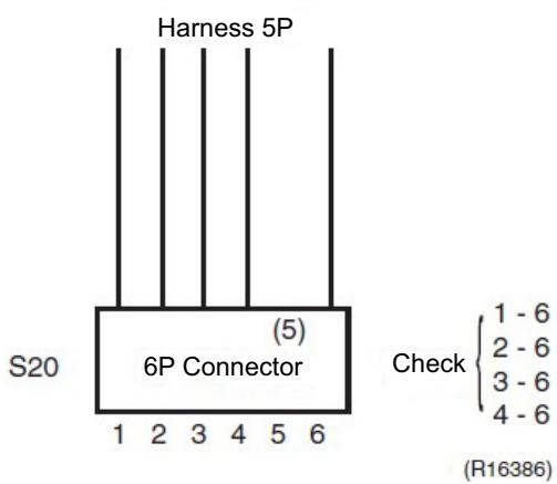
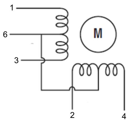
- If one or more of the windings have no continuity, replace the expansion valve coil.
2.4.2.4. Fan motor
| Technical specification | Description | ||
| The motor has a single connector for DC power and the rotation counter feed back from the integrated pulse generator (4 pulses/revolution). | The fan motor runs on a fixed speed to supply the required air flow rate. | ||
| Location | |||
| Piping diagram | Wiring diagram | Switch box | Component overview of unit |
| See "Outdoor unit" on page 104. | See "Outdoor unit" on page 99. | See "Outdoor unit" on page 111. | See "Outdoor unit" on page 110. |
| Check procedure | |||
| Mechanical check | |||
PRELIMINARY ACTIONS
- Switch off the Daikin unit via the user interface.
- Switch off the Daikin unit with the field supplied circuit breaker.
- Remove plate work when required (refer to "Basic removal" on page 68).
PROCEDURE
- Check the state of the propeller, replace the propeller if damaged, deformed, cracked or broken (refer to "Replacing propeller fan blade assembly" on page 85).
- Check the motor shaft bearing friction, only perform electrical check if motor runs with low shaft bearing friction. Replace fan motor if friction is abnormal (refer to "Replacing DC fan motor assembly" on page 79).
Electrical check
PRELIMINARY ACTIONS
- Switch off the Daikin unit via the user interface.
- Switch off the Daikin unit with the field supplied circuit breaker.
- Remove plate work when required (refer to "Basic removal" on page 68).
PROCEDURE
- Check fuse on PCB, replace if blown, see table "Component checklist" on page 111.

WARNING: RISK OF FIRE
When reconnecting a connector to the PCB, do not apply force, as this may damage the connector or connector pins of the PCB.
- Check if fan motor connector is plugged into PCB.
- Power the Daikin unit.
- Check power supply, the measured voltage must be 198 - 240 VAC, if not replace main PCB (refer to "Replacing main PCB" on page 84).
2.4.2.5. High pressure sensor
| Technical specification | Description | ||
| The pressure sensor is an analog pressure sensor. | The pressure sensor measures the pressure in the high pressure section of the refrigerant circuit. | ||
| Location | |||
| Piping diagram | Wiring diagram | Switch box | Component overview of unit |
| See "Outdoor unit" on page 104. | See "Outdoor unit" on page 99. | See "Outdoor unit" on page 111. | See "Outdoor unit" on page 110. |
| Check procedure | |||
| Electrical check | |||
PRELIMINARY ACTIONS
- Switch off the Daikin unit via the user interface.
- Switch off the Daikin unit with the field supplied circuit breaker.
- Remove plate work when required.
PROCEDURE
- Connect a pressure gauge to the high pressure service port and read the pressure.
- From the graph below, determine the expected sensor output signal.
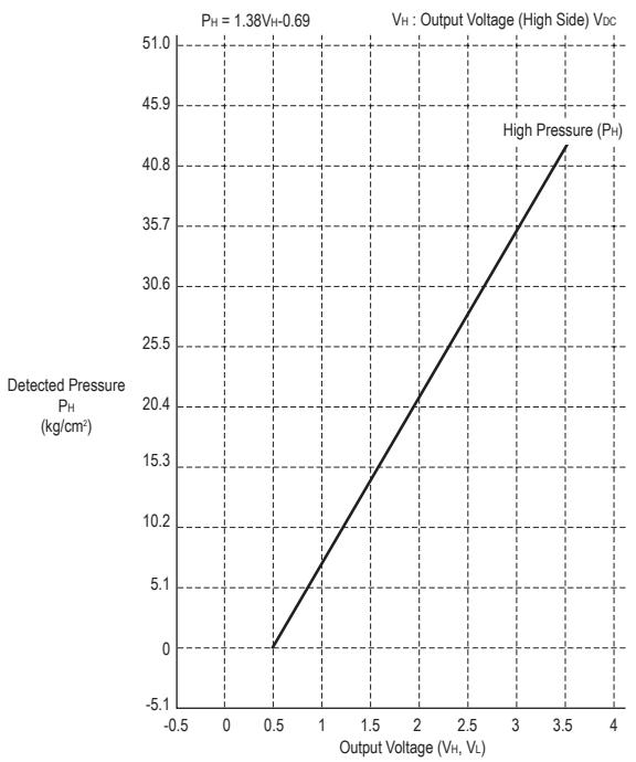
- Power the Daikin unit.

INFORMATION
To know where to plug in the pressure sensor connector, see "Component checklist" on page 111.
- Measure the voltage across high pressure sensor connector: pin 1-3 on the PCB; compare the measured voltage with the expected voltage.
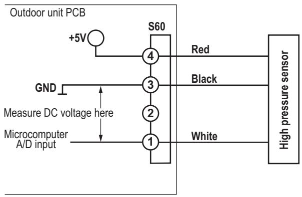
- In case no voltage is measured across high pressure sensor connector: pin 1-3; do following checks:

INFORMATION
If 1 or more checks fail, replace the high pressure sensor.
Check 1
- Check main PCB (refer to "Replacing main PCB" on page 84).
Check 2
- Check if the high pressure sensor connector is plugged into PCB.
Check 3
- Measure the voltage across high pressure sensor connector: pin 4-3; the measured voltage must be 5 VDC, if not replace PCB.
2.4.2.6. Main PCB
Not available yet.
2.4.2.7. Pressure sensor
| Technical specification | Description | ||
| The pressure sensor is an analog pressure sensor. | The pressure sensor measures the pressure in the high pressure section of the refrigerant circuit. | ||
| Location | |||
| Piping diagram | Wiring diagram | Switch box | Component overview of unit |
| See "Outdoor unit" on page 104. | See "Outdoor unit" on page 99. | See "Outdoor unit" on page 111. | See "Outdoor unit" on page 110. |
| Check procedure | |||
| Electrical check | |||
PRELIMINARY ACTIONS
- Switch off the Daikin unit via the user interface.
- Switch off the Daikin unit with the field supplied circuit breaker.
- Remove plate work when required.
PROCEDURE
- Connect a pressure gauge to the high pressure service port and read the pressure.
- From the graph below, determine the expected sensor output signal.
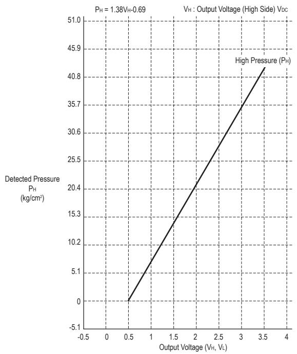
- Power the Daikin unit.

INFORMATION
To know where to plug in the pressure sensor connector, see "Component checklist" on page 111.
- Measure the voltage across high pressure sensor connector: pin 1-3 on the PCB; compare the measured voltage with the expected voltage.
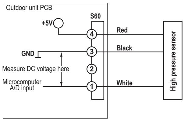
- In case no voltage is measured across high pressure sensor connector: pin 1-3; do following checks:

INFORMATION
If 1 or more checks fail, replace the high pressure sensor.
Check 1
- Check main PCB (refer to "Replacing main PCB" on page 84).
Check 2
- Check if the high pressure sensor connector is plugged into PCB.
Check 3
- Measure the voltage across high pressure sensor connector: pin 4-3; the measured voltage must be 5 VDC, if not replace PCB.
2.4.2.8. Refrigerant thermistors
| Technical specification | Description | ||
| A single type of thermistor is used; the resistance vs. temperature characteristics is shown in below table "Thermistor resistance / temperature characteristics (type 1)". | The thermistors are used to measure the temperature at multiple locations inside the Daikin unit. The measured temperatures are processed by the main board. | ||
| Location | |||
| Piping diagram | Wiring diagram | Switch box | Component overview of unit |
| See "Outdoor unit" on page 104. | See "Outdoor unit" on page 99. | See "Outdoor unit" on page 111. | See "Outdoor unit" on page 110. |
| Check procedure | |||
| Mechanical check | |||
PRELIMINARY ACTIONS
- Switch off the Daikin unit via the user interface.
- Switch off the Daikin unit with the field supplied circuit breaker.
- Locate the thermistor and check if thermal contact with the piping or ambient is ensured.
| Electrical check | |
| i | INFORMATION If a thermistor check fails, replace the thermistor. |
PRELIMINARY ACTIONS
- Switch off the Daikin unit via the user interface.
- Switch off the Daikin unit with the field supplied circuit breaker.
- Remove plate work when required.
PROCEDURE
- From the table in the appendix ("Component checklist" on page 111), select the thermistor that must be checked.
- Measure the temperature of the thermistor using a contact thermometer.
| ! | WARNING: RISK OF FIRE When reconnecting a connector to the PCB, do not apply force, as this may damage the connector or connector pins of the PCB. |
- Unplug the connector from the appropriate PCB and measure the resistance between the pins listed in the table in the appendix ("Component checklist" on page 111).
- Compare the measured resistance with the range determined by the lower and higher temperature.
- If the measured resistance does not match the listed value, the thermistor must be replaced.

INFORMATION
All thermistors have a tolerance of 5% .
E.g. R3T air thermistor - main PCB - connector S90: pin 1-2 type 1:
Measured temperature with contact thermometer: 23.1°C
Unplug the sensor and measure the resistance between S90: 1-2: 21.86 kΩ.
The resistance values are defined by below table "Thermistor resistance / temperature characteristics (type 1)":
- Resistance at 23°C : 21.85 kΩ.
-
Resistance at 24°C : 20.90 kΩ.
-
The measured value 21.86 kΩ is inside the range, thermistor R3T passes the check.

INFORMATION
The user interface allows to monitor most thermistors.
If the measured resistance of the thermistor matches the temperature measured with the contact thermometer but the temperature for the corresponding thermistor is not correct on the user interface display, replace applicable PCB.
Table 2-1: Thermistor resistance / temperature characteristics (type 1)
Table 2-2: Thermistor resistance / temperature characteristics (type 2)
| T°C | kΩ | T°C | kΩ | T°C | kΩ | T°C | kΩ | T°C | kΩ |
| -20 | 197.81 | 0 | 65.84 | 20 | 25.01 | 40 | 10.63 | 60 | 4.87 |
| -19 | 186.53 | 1 | 62.54 | 21 | 23.91 | 41 | 10.21 | 61 | 4.70 |
| -18 | 175.97 | 2 | 59.43 | 22 | 22.85 | 42 | 9.81 | 62 | 4.54 |
| -17 | 166.07 | 3 | 56.49 | 23 | 21.85 | 43 | 9.42 | 63 | 4.38 |
| -16 | 156.80 | 4 | 53.71 | 24 | 20.90 | 44 | 9.06 | 64 | 4.23 |
| -15 | 148.10 | 5 | 51.09 | 25 | 20.00 | 45 | 8.71 | 65 | 4.08 |
| -14 | 139.94 | 6 | 48.61 | 26 | 19.14 | 46 | 8.37 | 66 | 3.94 |
| -13 | 132.28 | 7 | 46.26 | 27 | 18.32 | 47 | 8.05 | 67 | 3.81 |
| -12 | 125.09 | 8 | 44.05 | 28 | 17.54 | 48 | 7.75 | 68 | 3.68 |
| -11 | 118.34 | 9 | 41.95 | 29 | 16.80 | 49 | 7.46 | 69 | 3.56 |
| -10 | 111.99 | 10 | 39.96 | 30 | 16.10 | 50 | 7.18 | 70 | 3.44 |
| -9 | 106.03 | 11 | 38.08 | 31 | 15.43 | 51 | 6.91 | 71 | 3.32 |
| -8 | 100.41 | 12 | 36.30 | 32 | 14.79 | 52 | 6.65 | 72 | 3.21 |
| -7 | 95.14 | 13 | 34.62 | 33 | 14.18 | 53 | 6.41 | 73 | 3.11 |
| -6 | 90.17 | 14 | 33.02 | 34 | 13.59 | 54 | 6.65 | 74 | 3.01 |
| -5 | 85.49 | 15 | 31.50 | 35 | 13.04 | 55 | 6.41 | 75 | 2.91 |
| -4 | 81.08 | 16 | 30.06 | 36 | 12.51 | 56 | 6.18 | 76 | 2.82 |
| -3 | 76.93 | 17 | 28.70 | 37 | 12.01 | 57 | 5.95 | 77 | 2.72 |
| -2 | 73.01 | 18 | 27.41 | 38 | 11.52 | 58 | 5.74 | 78 | 2.64 |
| -1 | 69.32 | 19 | 26.18 | 39 | 11.06 | 59 | 5.14 | 79 | 2.55 |
| 80 | 2.47 |
| T °C | kΩ | T °C | kΩ | T °C | kΩ | T °C | kΩ | T °C | kΩ |
| -20 | 192.08 | 0 | 64.17 | 20 | 24.45 | 40 | 10.41 | 60 | 4.87 |
| -19 | 181.16 | 1 | 60.96 | 21 | 23.37 | 41 | 10.00 | 61 | 4.70 |
| -18 | 170.94 | 2 | 57.94 | 22 | 22.35 | 42 | 9.61 | 62 | 4.54 |
| -17 | 161.36 | 3 | 55.08 | 23 | 21.37 | 43 | 9.24 | 63 | 4.38 |
| -16 | 152.38 | 4 | 52.38 | 24 | 20.45 | 44 | 8.88 | 64 | 4.23 |
| -15 | 143.96 | 5 | 49.83 | 25 | 19.56 | 45 | 8.54 | 65 | 4.08 |
| -14 | 136.05 | 6 | 47.42 | 26 | 18.73 | 46 | 8.21 | 66 | 3.94 |
| -13 | 128.63 | 7 | 45.14 | 27 | 17.93 | 47 | 7.90 | 67 | 3.81 |
| -12 | 121.66 | 8 | 42.98 | 28 | 17.17 | 48 | 7.60 | 68 | 3.68 |
| -11 | 115.12 | 9 | 40.94 | 29 | 16.45 | 49 | 7.31 | 69 | 3.56 |
| -10 | 108.96 | 10 | 39.01 | 30 | 15.76 | 50 | 7.04 | 70 | 3.44 |
| T°C | kΩ |
| -9 | 103.18 |
| -8 | 97.73 |
| -7 | 92.61 |
| -6 | 87.79 |
| -5 | 83.25 |
| -4 | 78.97 |
| -3 | 74.94 |
| -2 | 71.14 |
| -1 | 67.56 |
| T°C | kΩ |
| 11 | 37.18 |
| 12 | 35.45 |
| 13 | 33.81 |
| 14 | 32.25 |
| 15 | 30.77 |
| 16 | 29.37 |
| 17 | 28.05 |
| 18 | 26.78 |
| 19 | 25.59 |
| T°C | kΩ |
| 31 | 15.10 |
| 32 | 14.48 |
| 33 | 13.88 |
| 34 | 13.31 |
| 35 | 12.77 |
| 36 | 12.25 |
| 37 | 11.76 |
| 38 | 11.29 |
| 39 | 10.84 |
| T°C | kΩ |
| 51 | 6.78 |
| 52 | 6.53 |
| 53 | 6.53 |
| 54 | 6.53 |
| 55 | 6.29 |
| 56 | 6.06 |
| 57 | 5.84 |
| 58 | 5.43 |
| 59 | 5.05 |
| T°C | kΩ |
| 71 | 3.32 |
| 72 | 3.21 |
| 73 | 3.11 |
| 74 | 3.01 |
| 75 | 2.91 |
| 76 | 2.82 |
| 77 | 2.72 |
| 78 | 2.64 |
| 79 | 2.55 |
| 80 | 2.47 |
2.4.3. System
Not applicable.
2.4.4. Others
Not applicable.
2.5. Other capacity range
Not applicable.
Part 3. Repair
This part contains the following chapters:
Refrigerant repair procedures 61
Service tools 65
Unit specific repair procedures 66
3.1. Refrigerant repair procedures
Overview:
Refrigerant piping handling 61
Recovery procedure 61
Refrigerant pump down 63
Piping repair procedures 64
3.1.1. Refrigerant piping handling
Make sure the applied pressure is never higher than the unit design pressure as indicated on the nameplate (PS).
Work according the F-gas regulation and/or local regulations.
- Make sure the correct amount according the F-gas regulation label on the unit (factory + additional where required) of refrigerant is charged after repair.
- Make sure to use the appropriate equipment and tools according to the refrigerant and unit type.
- Charge non-azeotropic refrigerant (e.g. R-410A) always in a liquid state.
R32 can be charged in gas phase.
Make sure to use a digital scale (no charging cylinder).
- Execute correct vacuum drying procedure after repair work:
- -0,1 MPa / -760 mmHg / -750 Torr / -1 bar for at least 1 hour.
- Connect the unit according the available service ports, refer to "Recovery procedure" on page 61.
- Use related field setting where necessary to open expansion valve/solenoid valve.
3.1.2. Recovery procedure
3.1.2.1. Outdoor unit casing
- Switch off the Daikin unit via the user interface.
- Manually open the expansion valve (located on the outdoor unit).
- Connect the vacuum pump, manifold, recovery unit and refrigerant bottle to the service port as shown below. For the location of the service ports, refer to "Outdoor unit" on page 104.
In case of 1 service port at the stop valves
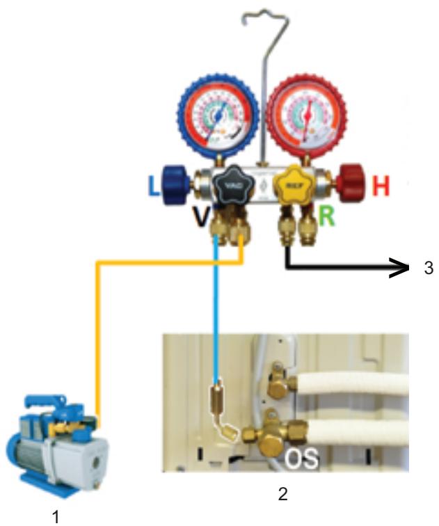
Figure 3-1: 1 service port at the stop valves
- Vacuum pump
- To recovery pump
- Connect flexible hose to service port 3 stop valve

INFORMATION
See instruction of the recovery pump supplier how to recover the refrigerant.
In case of 2 service ports at the stop valves
Connect both stop valve service ports to the manifold.
In case of 3 service ports at the stop valves
Connect 1 hose to the suction stop valve service port and 1 hose to the service port between the expansion valve and outdoor H/E.
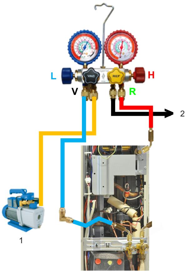
Figure 3-2: 3 service ports at the stop valves
-
Vacuum pump
-
To recovery pump

INFORMATION
See instruction of the recovery pump supplier how to recover the refrigerant.
3.1.3. Refrigerant pump down
This unit is equipped with an automatic pump down operation which will collect all refrigerant from the field piping and indoor unit in the outdoor unit. To protect the environment, make sure to perform the following pump down operation when relocating the unit.

WARNING: RISK OF EXPLOSION
- When the refrigeration circuit has a leak, do not execute pump down with the compressor.
- Use recovery system into separate cylinder.
- Warning, explosive hazard exists when executing pump down.
- Pump down with compressor can lead to self-combustion due to air entering during pump down.

INFORMATION
Some outdoor units are equipped with a low pressure switch to protect the compressor by switching it off.
Never short-circuit the low pressure switch during pump down operation!
3.1.3.1. Small outdoor unit
- Remove the valve lid from liquid stop valve and gas stop valve.
- Carry out pump down operation.

CAUTION
Refer to Installer Reference Guide for 'Pump down operation' procedure.
- After 5-10 min (after only 1-2 min in case of very low Ta < -10°C ), close the liquid stop valve with a hexagonal wrench.
- Check on manifold if vacuum is reached, close gas stop valve and forced cooling operation.
3.1.3.2. Large outdoor unit
- Stop all demands for the Daikin unit.
- Switch OFF / ON the power supply of the outdoor unit.
- Carry out pump down operation.

CAUTION
Refer to Installer Reference Guide for 'Pump down operation' procedure.
- The compressor and outdoor fan will start automatically.
- Request heating via remote controller to prevent HE freeze-up.
- a. Check on manifold if vacuum is reached, close gas stop valve and forced cooling operation.
b. Once operation stops (after 3 to 5 minutes), close the liquid and the gas stop valve. - Pump down is now finished. U4 may be displayed on the remote controller, this is not a malfunction.
- (After "pump down" is finished or stopped, keep the circulation pump running for at least 5 minutes.)
- Switch OFF the power supply of the outdoor unit.

NOTE
Make sure to re-open both stop valves before restart operation of the unit.
After a finished or stopped pump down, the unit will perform a test run at first operation (same as during commissioning).
3.1.4. Piping repair procedures
-
Make sure to cover open pipe ends during repair work so no dust or moisture can enter.
Make sure to re-apply insulation removed during repair.
Pipe expansion / flare making: -
Remove any burrs on the cut surface and use correct tool such as reamer or scraper (note that excessive deburring can thin the pipe walls and cause cracking of the pipe).
- Make sure the flare has the correct size (use a flare gauge).
- Make sure no particles remain in the piping.
- Apply just a drop of refrigerant oil on the inner surface of the flare.
- Make sure the flare connection is tightened with the correct torque (torque values refer to installation manual).
Brazing:
- Use correct brazing tool.
- Use a phosphor copper filler metal (silver composition of 0 to 2% ). Do not use flux material.
- Flush the piping before brazing with nitrogen to avoid oxidation of the inside of the copper tubes (nitrogen purity ≥ 99,99% ).
3.2. Service tools
For an overview of the applicable service tools, please check the Daikin Business Portal: http://www.mydaikin.eu
Go to the tab "After-sales support" on the left side and then select "Technical support".

You will then find a button "Service tools" which gives you an overview on which service tool to use for which product. Also additional information on the service tool (instruction, latest software) can be found there.
3.3. Unit specific repair procedures
Overview:
Indoor unit 67
Outdoor unit 68
Basic removal 68
Replacing switch box 71
Replacing 4-way valve body. 73
Replacing 4-way valve coil 75
Replacing compressor 76
Replacing DC fan motor assembly 79
Replacing expansion valve body 81
Replacing expansion valve motor 82
Replacing main PCB 84
Replacing propeller fan blade assembly 85
Replacing thermistors 87
Setting test mode for inverter checker 88
3.3.1. Indoor unit
Not applicable.
3.3.2. Outdoor unit
3.3.2.1. Basic removal
3.3.2.1.1 Single fan outdoor unit
3.3.2.1.2 Removing refrigerant connection cover
PRELIMINARY ACTIONS
- Switch off the Daikin unit via the user interface.
- Switch off the Daikin unit with the field supplied circuit breaker.
PROCEDURE
Removal
- Loosen and remove 1 screw (1) that fix the refrigerant connection cover.
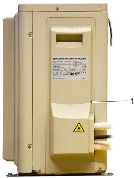
Figure 3-3: Removing refrigerant connection cover
1. Screw
3.3.2.1.3 Removing the top plate
PRELIMINARY ACTIONS
- Switch off the Daikin unit via the user interface.
- Switch off the Daikin unit with the field supplied circuit breaker.
PROCEDURE
Removal
- Loosen and remove the 2 screws (1) that fix the top plate.
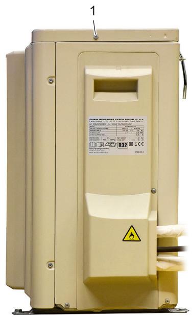
Figure 3-4: Removing the top plate
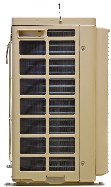
1. Screw
3.3.2.1.4 Removing the front plate
PRELIMINARY ACTIONS
- Switch off the Daikin unit via the user interface.
- Switch off the Daikin unit with the field supplied circuit breaker.
PROCEDURE
Removal
- Remove the top plate.
- Loosen and remove the 8 screws (1) that fix the front plate.
Figure 3-5: Removing the front plate
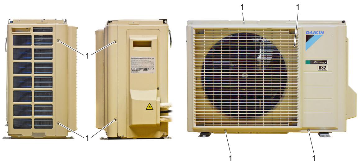
1. Screw
3.3.2.1.5 Removing the compressor sound insulation
PRELIMINARY ACTIONS
- Switch off the Daikin unit via the user interface.
- Switch off the Daikin unit with the field supplied circuit breaker.
PROCEDURE
Removal
- Remove the top plate.
- Remove the front plate.
- Remove the compressor sound insulation (untwist the cord and remove the insulation).
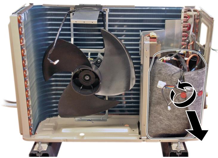
Figure 3-6: Removing the compressor sound insulation
3.3.2.2. Replacing switch box
PRELIMINARY ACTIONS
- Switch off the Daikin unit via the user interface.
- Switch off the Daikin unit with the field supplied circuit breaker.
- Remove plate work when required, refer to "Basic removal" on page 68.
PROCEDURE
Removal
- Remove the insulation (1).

WARNING: RISK OF FIRE
When reconnecting a connector to the PCB, do not apply force, as this may damage the connector or connector pins of the PCB.
- Unplug all connectors from the main PCB (2), see "Component checklist" on page 121.
- Remove all electrical power wiring (3) from the wire terminals (4).
- Remove the screws (5) that fix the wire clamp (6), remove the wire clamp (6).
- Remove the screws (7) that fix the right side plate assembly (8).
- Cut the cable tie (9).
- Lift the switch box (10) from the Daikin unit.
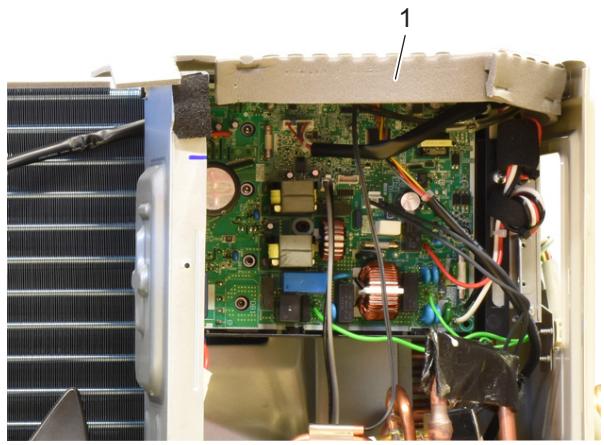
Figure 3-7: Removing the switch box
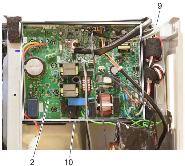
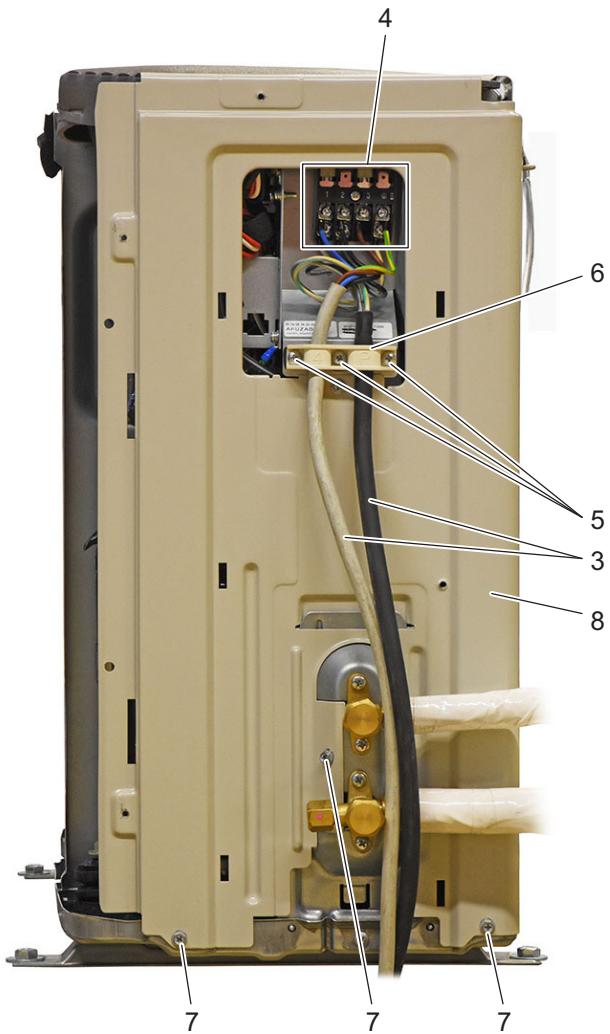
- Insulation
- Main PCB
- Electrical power wiring
- Wire terminals
-
Screw
-
Wire clamp
- Screw
- Right side plate assembly
- Cable tie
- Switch box
Installation
- Proceed in reverse order.
3.3.2.3. Replacing 4-way valve body
PRELIMINARY ACTIONS
- Switch off the Daikin unit via the user interface.
- Switch off the Daikin unit with the field supplied circuit breaker.
- Recover the refrigerant, refer to "Recovery procedure" on page 61.
- Remove plate work when required (refer to "Basic removal" on page 167).
PROCEDURE
Removal
- Remove any parts that block the way to the 4-way valve.

INFORMATION
Follow local regulations and Daikin refrigerant repair procedures during the repair of your unit, refer to "Refrigerant repair procedures" on page 79.

CAUTION
The maximum applied Nitrogen pressure must not exceed 0.02MPa
- Cut the 4-way valve pipes (2).
- Remove the 4-way valve (5).
- Recuperate the putty (3).
- Recuperate the insulation (4).
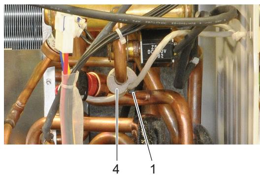
Figure 3-8: Removing the 4-way valve
- Tie wrap
- 4-way valve pipe
- Putty
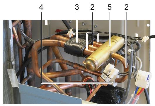
- Insulation
- 4-way valve
Installation

WARNING
Overheating the 4-way valve will damage or destroy it.
- Wrap a wet rag around the 4-way valve (5).

INFORMATION
Install the putty on the 4-way valve.
Install the compressor sound insulation in the same location.
- Proceed in reverse order.
3.3.2.4. Replacing 4-way valve coil
PRELIMINARY ACTIONS
- Switch off the Daikin unit via the user interface.
- Switch off the Daikin unit with the field supplied circuit breaker.
- Remove plate work when required.
- Remove any part that block the way to the 4-way valve coil.
PROCEDURE
Removal
- Loosen and remove the screw (1) that fixes the 4-way valve coil (3).
- Cut the tie wraps that fix the 4-way valve coil wiring.

WARNING: RISK OF FIRE
When reconnecting a connector to the PCB, do not apply force, as this may damage the connector or connector pins of the PCB.
- Unplug 4-way valve connector from PCB.
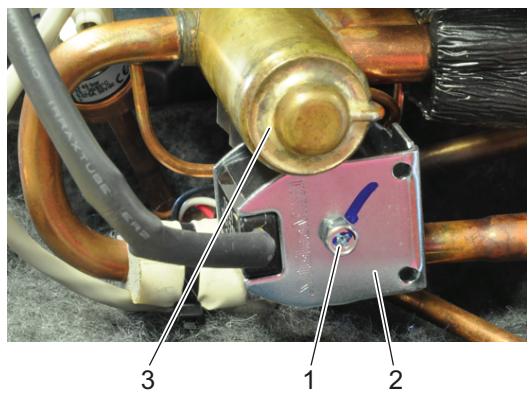
Figure 3-9: Removing the 4-way valve coil
- Screw
- Tie wrap
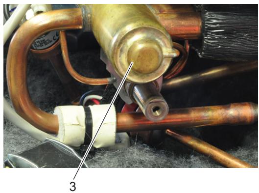
- 4-way valve coil
Installation
- Proceed in reverse order.
3.3.2.5. Replacing compressor
PRELIMINARY ACTIONS
- Switch off the Daikin unit via the user interface.
- Switch off the Daikin unit with the field supplied circuit breaker.
- Recover the refrigerant, refer to "Recovery procedure" on page 53.
- Remove plate work when required.
- Remove any part that blocks the way to the compressor.
PROCEDURE

INFORMATION
Follow local regulations and Daikin refrigerant repair procedures during the repair of your unit, refer to "Refrigerant repair procedures" on page 53.

CAUTION
The maximum applied Nitrogen pressure must not exceed 0.02MPa
Removal
- Remove the terminal cover (3) and unplug the compressor wiring (4) and take picture.
- Using a pipe cutter, cut the compressor pipes (5) below the soldered joint.
- Loosen and remove the 3 nuts (6) that fix the compressor (7).
- Remove the compressor (7).
- Remove the dampers (9) with bushings (10) from the compressor (7).
- Recuperate the putty (8).
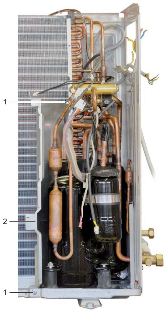
Figure 3-10: Removing the compressor
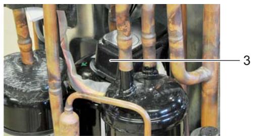
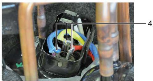
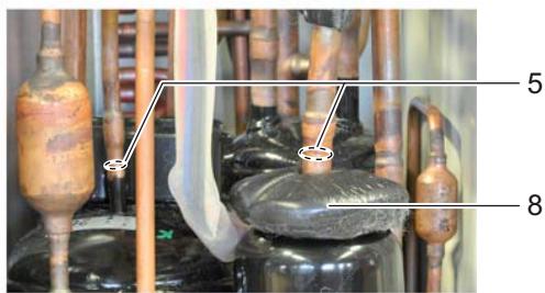
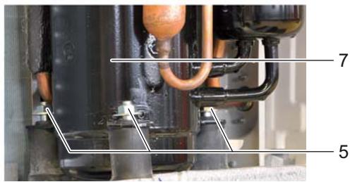
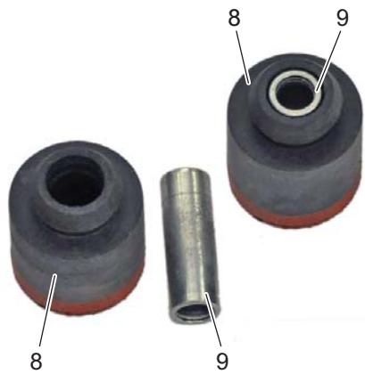
- Screw
- Partition plate assembly
- Terminal cover
- Compressor wiring
-
Compressor pipe
-
Nut
- Compressor
- Putty
- Dampers
- Bushing
Installation
| ! | CAUTION The oil in the compressor is hygroscopic. Remove the caps from the compressor piping as late as possible. |
| INFORMATION Before installing a new compressor, determine the cause of the compressor failure and take all required corrective actions. | |
| INFORMATION If the dampers are worn, replace the dampers. The bushings inside the dampers are recuperated for use with the new dampers. | |
| INFORMATION Install the putty on the compressor. Install the compressor sound insulation in the same location. |
- Check damper status, replace when worn.
- First install the 3 (new) dampers (without the bushings) on the new compressor.
- Install the 3 bushings in the dampers.
- When installing the new compressor, remove the caps from the compression pipe and the suction pipe as late as possible.
- When soldering the compressor pipes, cover the compressor pipes with a wet cloth to prevent overheating the compressor (and the oil in the compression pipe).
- Proceed in reverse order.
3.3.2.6. Replacing DC fan motor assembly
PRELIMINARY ACTIONS
- Switch off the Daikin unit via the user interface.
- Switch off the Daikin unit with the field supplied circuit breaker.
- Remove the propeller fan blade assembly, refer to "Replacing propeller fan blade assembly" on page 149.
PROCEDURE
Removal
- Remove the insulation (1) from the switch box.
- Unplug the fan motor connector (3) from the main PCB.

WARNING: RISK OF FIRE
When reconnecting a connector to the PCB, do not apply force, as this may damage the connector or connector pins of the PCB.
- Release the fan motor assembly harness (2) from the slot (4).
- Slightly bend the harness retainers (5) to release the fan motor assembly harness (2).
- Loosen and remove the screws (6) that fix the DC fan motor assembly (7).
- Remove the DC fan motor assembly (7).
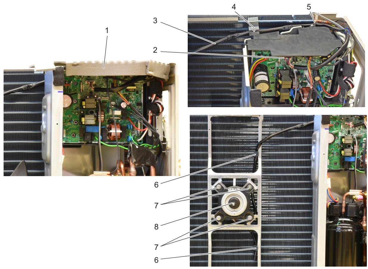
Figure 3-11: Removing the DC fan motor assembly
- Insulation
- Fan motor assembly harness
- Connector
-
Slot
-
Harness retainer
- Screw
- Fan motor assembly
Installation
- Proceed in reverse order.
3.3.2.7. Replacing expansion valve body
PRELIMINARY ACTIONS
- Switch off the Daikin unit via the user interface.
- Switch off the Daikin unit with the field supplied circuit breaker.
- Remove the expansion valve motor, refer to "Replacing expansion valve motor" on page 82.
- Remove plate work when required.
- Remove any part that block the way to the expansion valve body.
PROCEDURE

INFORMATION
Follow local regulations and Daikin refrigerant repair procedures during the repair of your unit, refer to "Refrigerant repair procedures" on page 61.

CAUTION
The maximum applied Nitrogen pressure must not exceed 0.02MPa
Removal
- Recuperate the putty (1).
- Using a pipe cutter, cut the expansion valve body pipes (2).
- Remove the expansion valve body (3).
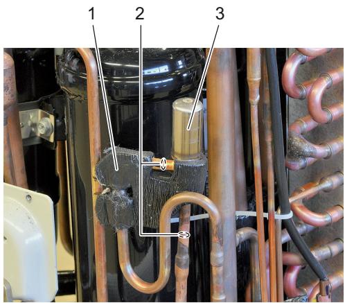
Figure 3-12: Removing the expansion valve
- Putty
-
Expansion valve pipe
-
Expansion valve
Installation

WARNING
Overheating the expansion valve body will damage or destroy it.
- Wrap a wet rag around the expansion valve body (3).

INFORMATION
Install the putty on the expansion valve body piping.
- Proceed in reverse order.
3.3.2.8. Replacing expansion valve motor
PRELIMINARY ACTIONS
- Switch off the Daikin unit via the user interface.
- Switch off the Daikin unit with the field supplied circuit breaker.
- Remove plate work when required.
- Remove any part that block the way to the expansion valve motor.
PROCEDURE
Removal

WARNING: RISK OF FIRE
When reconnecting a connector to the PCB, do not apply force, as this may damage the connector or connector pins of the PCB.
- Remove the expansion valve motor (1) from the expansion valve body (2).
- Unplug expansion valve motor connector from PCB.
- Cut all tie wraps that fix the expansion valve motor (1) wiring.
Figure 3-13: Removing the expansion valve motor
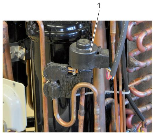
1. Expansion valve motor
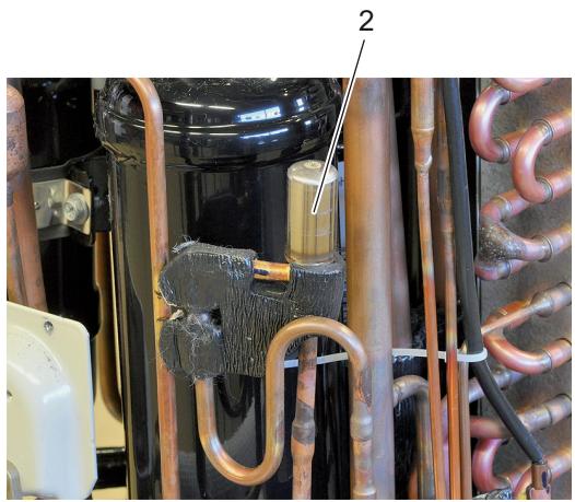
2. Expansion valve
Installation

INFORMATION
Replace all tie wraps that were cut during removal.
- Proceed in reverse order.

INFORMATION
The expansion valve motor (3) is equipped with a pipe retention clip (1). The pipe retention clip (1) must be placed over the pipe (2) to lock the expansion valve motor (3).
- When installing the expansion valve motor (3), lock it on the expansion valve.
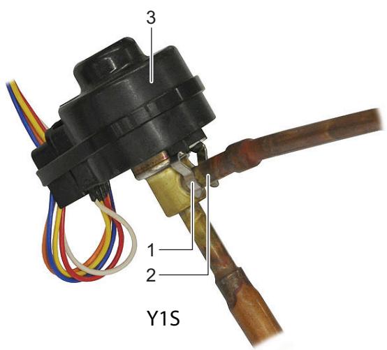
Figure 3-14: Locking the expansion valve motor
-
Pipe retention clip
-
Expansion valve motor
-
Pipe
3.3.2.9. Replacing main PCB
PRELIMINARY ACTIONS
- Switch off the Daikin unit via the user interface.
- Switch off the Daikin unit with the field supplied circuit breaker.
- Remove the switch box, refer to "Replacing switch box" on page 71.
PROCEDURE
Removal
- Cut the 2 cable ties (1).
- Loosen and remove the screw (2).
- Loosen and remove the 5 screws (3).
- Press the 2 latches (5) to unlock and remove the main PCB (4).
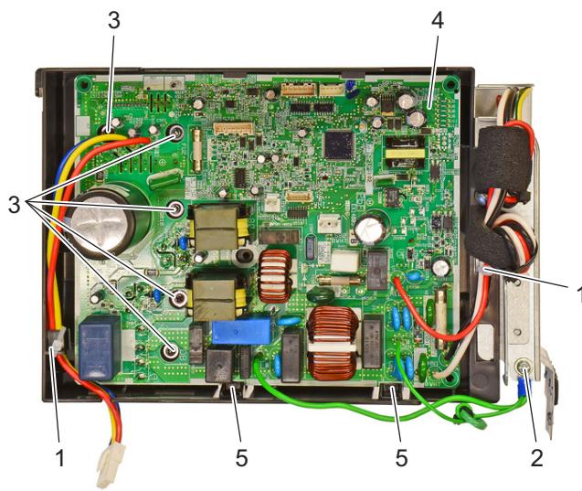
Figure 3-15: Removing the main PCB
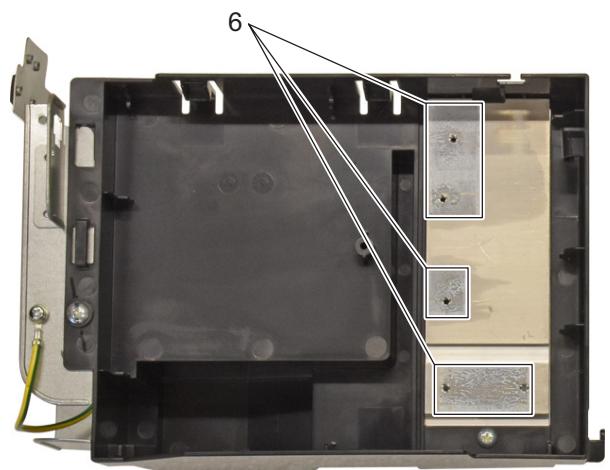
- Cable tie
- Screw
-
screw
-
Main PCB
- Latch
- Heat sink compound
Installation
- Apply Heat sink compound (6) before joining the main PCB and the heat sink.
- Proceed in reverse order.
3.3.2.10. Replacing propeller fan blade assembly
PRELIMINARY ACTIONS
- Switch off the Daikin unit via the user interface.
- Switch off the Daikin unit with the field supplied circuit breaker.
- Remove the propeller fan blade assembly, refer to "Replacing propeller fan blade assembly" on page 149.
PROCEDURE
Removal
- Remove the insulation (1) from the switch box.
- Unplug the fan motor connector (3) from the main PCB.

WARNING: RISK OF FIRE
When reconnecting a connector to the PCB, do not apply force, as this may damage the connector or connector pins of the PCB.
- Release the fan motor assembly harness (2) from the slot (4).
- Slightly bend the harness retainers (5) to release the fan motor assembly harness (2).
- Loosen and remove the screws (6) that fix the DC fan motor assembly (7).
- Remove the DC fan motor assembly (7).
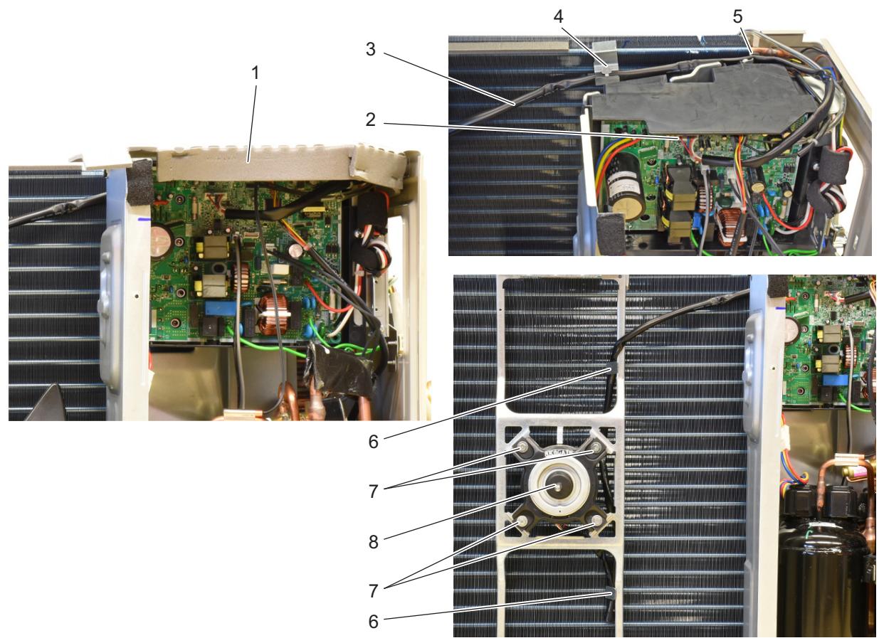
Figure 3-16: Removing the DC fan motor assembly
- Insulation
- Fan motor assembly harness
- Connector
-
Slot
-
Harness retainer
- Screw
- Fan motor assembly
Installation
- Proceed in reverse order.
3.3.2.11. Replacing thermistors
PRELIMINARY ACTIONS
- Switch off the Daikin unit via the user interface.
- Switch off the Daikin unit with the field supplied circuit breaker.
- Remove plate work when required, see "Basic removal" on page 68.
PROCEDURE
Removal
- Locate thermistor that needs to be replaced, see "Component checklist" on page 121.
- Cut the tie wraps (1) that fix the insulation (3) and the thermistor wire (2).
- Cut the insulation (3) and remove it.
- Pull the clip (5) that fixes the thermistor (6).
- Remove the thermistor (6) from the thermistor holder (4).
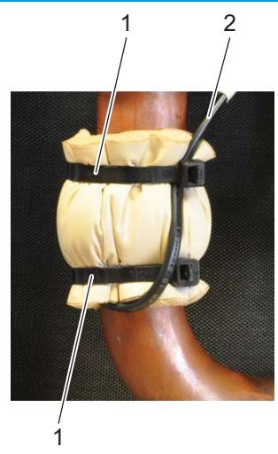
Figure 3-17: Replacing a thermistor
- Tie wrap
- Thermistor wire
- Insulation
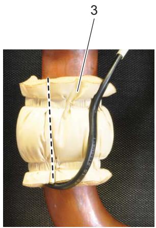
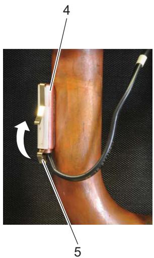
- Thermistor holder
- Clip
- Thermistor
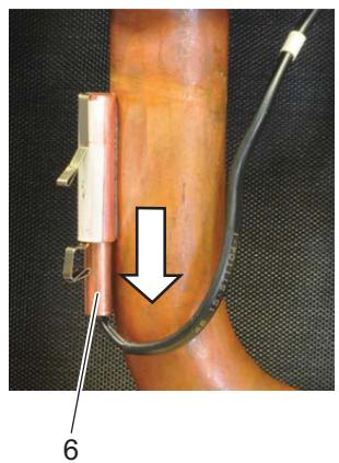
Installation
- Proceed in reverse order.
3.3.2.12. Setting test mode for inverter checker
3.3.2.12.1 For 2MXM outdoor units
Activate power transistor test operation from the indoor unit with the remote controller.
ARC466 Series
- Turn the system on.
- Select FAN operation with the [MODE] button on the remote controller.
- Press the 3 buttons (TEMP▲, TEMP▼, MODE) simultaneously. → SC is displayed.
- Press the TEMP▲ or TEMP▼ button and select "l".
- Press the [MODE] button. → Trial operation is activated
- Press the [ON/OFF] button. → Power transistor test operation starts.
ARC452, ARC433 Series
- Turn the system on.
- Select FAN operation with the [MODE] button on the remote controller.
- Press the 3 buttons (TEMP▲, TEMP▼, MODE) simultaneously. → 00 is displayed, the left digit is blinking
- Press the [MODE] button. → 00 is displayed, the right digit is blinking.
- Press the [MODE] button. → "i" is displayed
- Press the [ON/OFF] button. → Power transistor test operation starts.
3.3.2.12.2 For 3 to 5 MXM outdoor units
Activate the power transistor test operation from the outdoor unit.
- Press the forced cooling operation ON/OFF (push button SW1 on Service PCB) for 5 seconds, refer to "Outdoor unit" on page 97
Part 4. Maintenance
This part contains the following chapters:
Indoor unit 89
Outdoor unit 90
4.1. Indoor unit

WARNING
Before performing any maintenance, power off the unit.

INFORMATION
After all checks are made, make sure the water and brine circuits are filled properly again and fluid pressures are in line with regulations (± 2 bar).
4.1.1. General maintenance
1. Optimal operation conditions
| Cooling | Heating | |
| Differential between suction temperature and discharge temperature | 8~18°C | 14~30°C |
| DB | 27°C | 20°C |
| WB | 19°C | Not applicable |
2. Correlation of air-conditioner's operation status, pressure and running current
| COOLING | Low pressure | High pressure | Running current |
| Dirty air filter | Lower | Lower | Lower |
| Short circuit of air inlet/outlet | Lower | Lower | Lower |
| Air mixed in refrigerant | Higher | Higher | Higher |
| Water mixed in refrigerant | Lower* | Lower | Lower |
| Dirt mixed in refrigerant | Lower** | Lower | Lower |
| Refrigerant shortage (gas) | Lower | Lower | Lower |
| Unsatisfactory compression | Higher*** | Lower | Lower |
- Water in the refrigerant freezes inside the electronic expansion valve and is basically the same phenomenon as pump down.
Dirt in the refrigerant clogs filters inside the piping and is basically the same phenomenon as pump down.
* Pressure differential between high and low pressure becomes low.
4.2. Outdoor unit
4.2.1. General maintenance outdoor unit
1. Outdoor unit coil
- Straighten hair fins.
- Clear coil from dust, leaves, etc. with a fin-comb, or compressed air/N2. Avoid bending or damaging of the Alu fins during the cleaning process.

CAUTION
Make sure not to bend the hair fins.
- Correlation of air-conditioner's operation status, pressure and running current.
| COOLING | Low pressure | High pressure | Running current |
| Dirty air filter | Higher | Higher | Higher |
| Short circuit of air inlet/outlet | Higher | Higher | Higher |
| Air mixed in refrigerant | Higher | Higher | Higher |
| Water mixed in refrigerant | Lower* | Lower | Lower |
| Dirt mixed in refrigerant | Lower** | Lower | Lower |
| Refrigerant shortage (gas) | Lower*** | Lower | Lower |
- Water in the refrigerant freezes inside the electronic expansion valve and is basically the same phenomenon as pump down.
Dirt in the refrigerant clogs filters inside the piping and is basically the same phenomenon as pump down.
* Pressure differential between high and low pressure becomes low.
Part 5. Appendix
This part contains the following chapters:
Field setting 93
Detailed information setting mode 97
Wiring diagram 98
Piping diagram 104
Component overview of unit 110
Product specific information 111
Switch box 111
Field information report 112
5.1. Field setting
5.1.1. Indoor unit
5.1.1.1. Indoor fan control during thermostat off in cooling
Model:FTXM-M,ATXM-M(BMS)/Remote controller:ARC466A33
Software logic change for thermostat OFF is for cooling operation (to increase SEER) (for main stream models FTXM/CTXM).
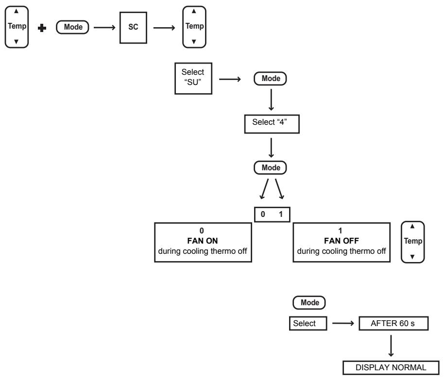
Figure 5-1: How to change fan OFF to ON when in cooling thermo off
Model FTX25/35KM does not have remote controller which has such service mode.
Change fan on/off by remote controller (ARC480A11) in service mode.
- Normal operation on remote controller.
- Press "temperature (upper/ lower) button" with "off button" in same timing (→ go to "SC" service mode).
- Press "temperature button" ( → "SC → A → 7 → SU" rotation = segment 1), select SU and press "fan button" as decision ( → number is displayed at the lower left).
- Press "temperature button" ( → 1~10), select 4 and press "fan button" as decision ( → number is displayed at the lower right).
- Press "temperature button" (→ 0 1) , select 0 and press "fan button" as decision (0: fan ON, 1: fan OFF).
5.1.1.2. Brightness setting of multi-coloured lamp of the indoor unit
- Press TEMP and MODE buttons simultaneously.
- SC is displayed on the screen.
- Select L (light) with TEMP buttons up or down.
- Press MODE button to enter brightness setting mode.
- Press TEMP up or down to adjust brightness to L (low), H (high) or OFF.
- Press MODE button again for 5 seconds to exit.
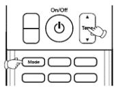
5.1.1.3. ON/OFF button on the indoor unit
- Shortly press ON/OFF button indoor: auto, 25°C , auto fanspeed. To de-activate: shortly press ON/OFF again.
- Press ON/OFF button indoor 5-9 seconds: forced operation mode = forced cooling. To de-activate: press again for 10 seconds.
5.1.2. Outdoor unit
5.1.2.1. Facility setting for outdoor split units
This function is designed for facilities such as equipment or computer rooms. It is never to be used in a residence or office where people occupy the space.
Cutting jumper 6 (J6) on the circuit board will expand the operation range down to -15°C . However it will stop if the outdoor temperature drops below -20°C and start back up once the temperature rises again.
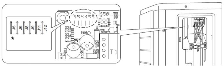
Figure 5-2: Jumper settings
- Cut J6 with nippers or a similar tool
Other jumper settings
J5: No function for this unit.
J8: Cold region setting (changing the operating range from - 10°C to -15°C ).
J9: No function for this unit.
J11: Protection for error memory overwrite (only to be used during development).
J12: No function for this unit.
5.1.2.2. Multi split outdoor
5.1.2.2.1 Wiring error check
This product is capable of automatic correction of wiring error.
Press the "wiring error check switch" on the outdoor unit service PC board. However, the wiring error check switch will not function for 3 minutes after the safety breaker is turned on; or depending on the outside air conditions (see note 2). About 15 - 20 minutes after the switch is pressed, the errors in the connection wiring will be corrected.
If self-correction is not possible, check the indoor unit wiring and piping in the usual manner.
| LED | 1 | 2 | 3 | 4 | 5 | Message |
| Status | All flashing (simultaneously) | Autonomic correction impossible | ||||
| Flashing (on after another) | Autonomic correction completed | |||||
| ( one or more LEDs 1 to 4 are ON) | Abnormal stop (note 4) | |||||
Figure 5-3: Service PC board wiring error check switch location
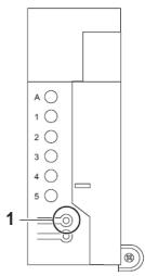
1. Wiring error check switch (SW3)
Note
- For two rooms, LED3, 4 and 5 are not present, and for three rooms, LED4 and 5 are not present, and for four rooms LED 5 is not present.
- If the outside air temperature is 5°C or less, the wiring error check function will not operate.
- After wiring error check operation is completed, LED indication will continue until ordinary operation starts.
This is normal. - Follow the product diagnosis procedures (details of product error diagnosis are listed on the back of the fight side plate).
5.1.2.2.2 Dip switch settings
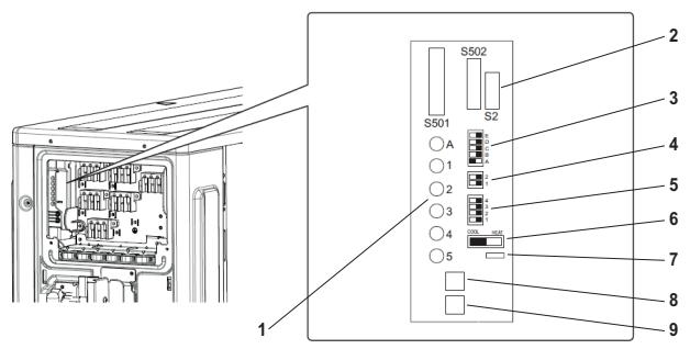
Figure 5-4: Dip switch location
- Service monitor LEDs
- Connector for D checker
- SW4
- SW6
-
SW5
-
Cool/heat selector
7.J_DP jumper - SW3
- SW1
| SW1 | Forced operation • In combination with the cool/heat selector switch the unit can be started in cooling or heating. • Is also used to activate the inverter checker mode. |
| SW3 | Cross wiring check (figure 5-4 on page 95). |
| J_DP jumper | Not used. |
| Cool/heat selector | • Used in combination with the SW1. • Must be set in cooling for pump down operation. |
| SW4 | Priority room setting. The indoor unit for which priority room setting is applied takes priority in the following cases. 1-1 Operation mode priority The operation mode of the indoor unit which is set for priority room setting takes priority. If the set indoor unit is operating, all other indoor units do not operate and enter standby mode, according to the operation mode of the set indoor unit. 1-2 Priority during high-power operation If the indoor unit which is set for priority room settings is operating at high power, the capabilities of other indoor units will be some-what reduced. Power supply gives priority to the indoor unit which is set for priority room setting. 1-3 Quiet operation priority Setting the indoor unit to quiet operation will make the indoor unit run quietly. Setting procedure Slide the switch to the ON side for the switch that corresponds to the piping connected to the indoor unit to be set (in the figure below, it is room A). BE SURE TO SET ONLY ONE ROOM. ON OFF E D C B A |
| SW5 | SW5-1 Heat mode lock • This setting will force the unit to only operate in heating. SW5-2 to SW5-4 • Not used. |
| SW6 | SW6-1 Night quiet mode About Night Quiet Mode The Night Quiet Mode function reduces operating noise of the outdoor unit at night time. This function is useful if the customer is worried about the effects of the operating noises on the neighbours. SW6-2 • Not used. |
5.1.2.2.3 Cool mode lock
- Use the S15 connector to set the unit to cool only. Short-circuit pins 3 and 5 of the connector S15 to set to only cool (C).
The following specifications apply to the connector housing and pins.
ST products Housing: VHR-5N
Pin:SVH-21T-1,1
Figure 5-5: S15 connector location
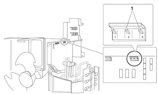
1. S15 connector pins 3-5
5.1.2.2.4 Multi Split outdoor jumper settings
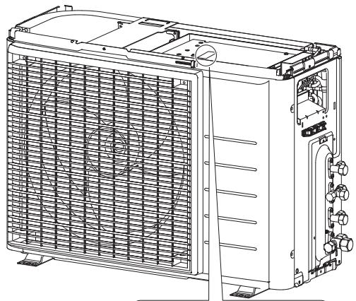
Figure 5-6: Jumper location
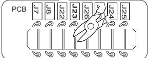
| J7 | Night quiet mode setting |
| J8 | Not used |
| J12 | Cold region setting for defrost change |
| J22 | Not used |
| J23 | Econo mode prohibition setting |
| J24 | Not used |
| J25 | Not used |
| J26 | Cold region setting for increased max. Hz at low ambient |
5.1.3. Remote controller
Not applicable.
5.2. Detailed information setting mode
5.2.1. Indoor unit
Not available.
5.2.2. Outdoor unit
Not available.
5.2.3. Remote controller
Not available.
5.3. Wiring diagram
5.3.1. Indoor unit
Not applicable.
5.3.2. Outdoor unit
5.3.2.1. 2MXM50M
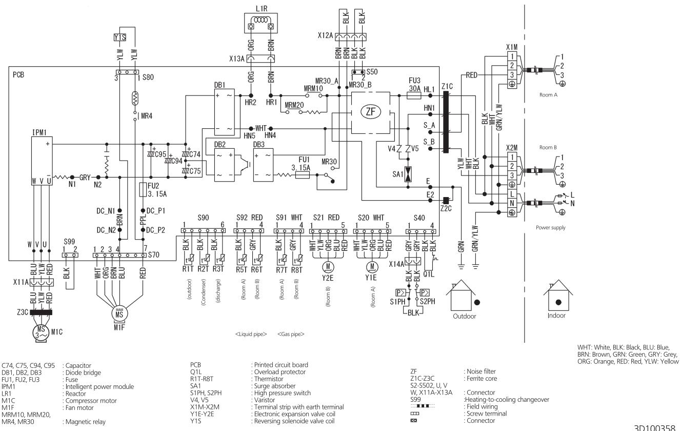
Figure 5-7: Wiring diagram - outdoor unit 2MXM50M
5.3.2.2. 3MXM68M
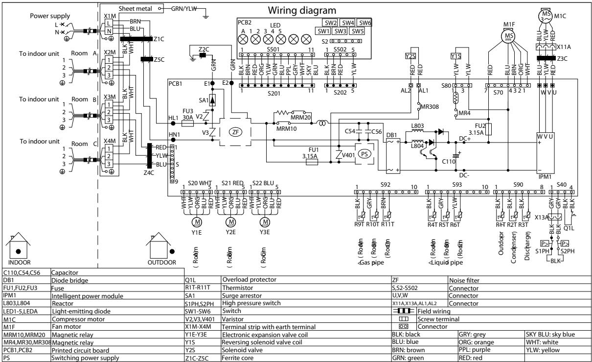
Figure 5-8: Wiring diagram - outdoor unit 3MXM68M
3D100359A
5.3.2.3. 4MXM-M
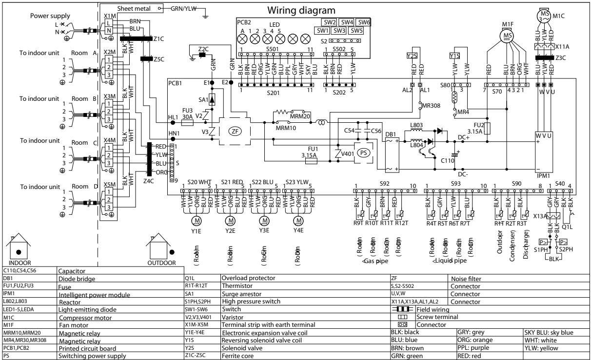
Figure 5-9: Wiring diagram - outdoor unit 4MXM-M
3D100361A
5.3.2.4. 5MXM-M
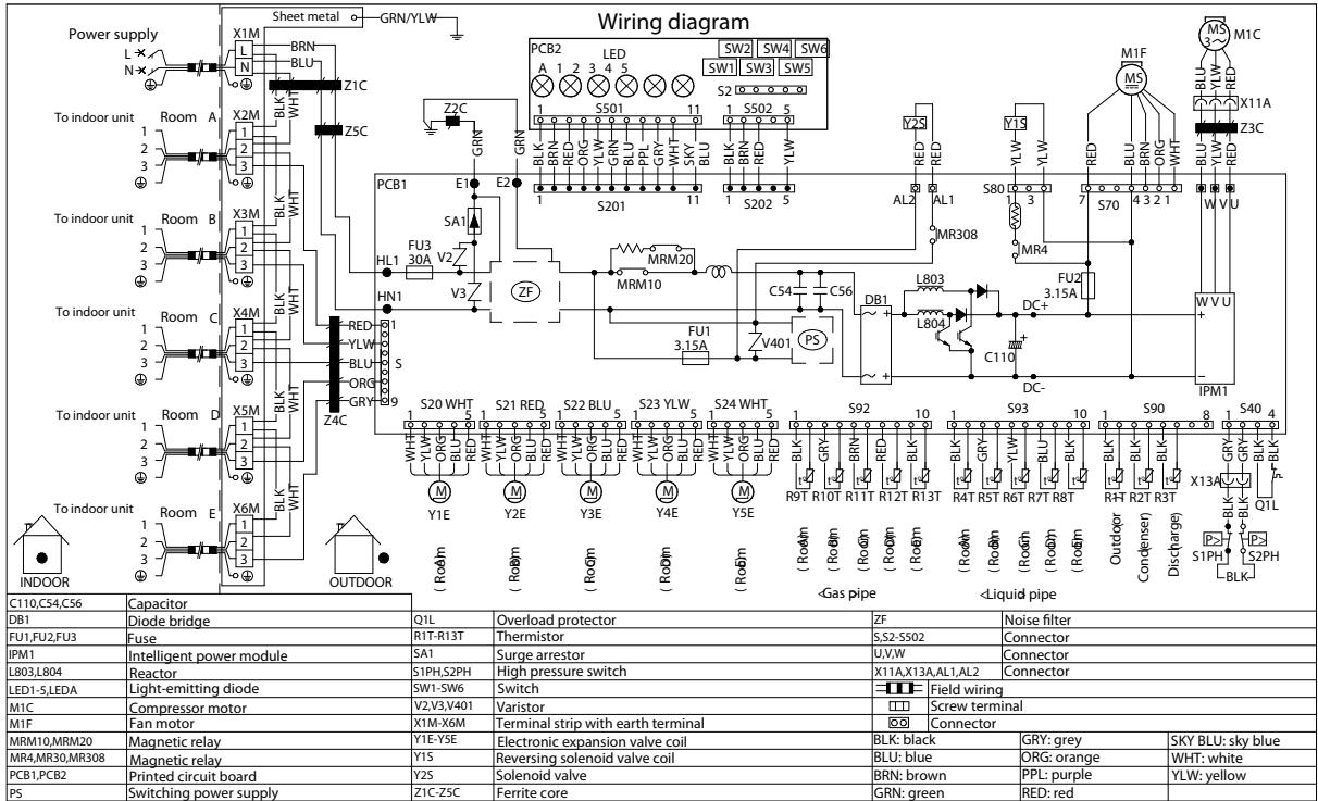
Figure 5-10: Wiring diagram - outdoor unit 2MXM50M
3D100360A
5.3.2.5.RXJ20-35M

Figure 5-11: Wiring diagram - outdoor unit RXJ20-35M
4D099916B
5.3.2.6.RXJ50M
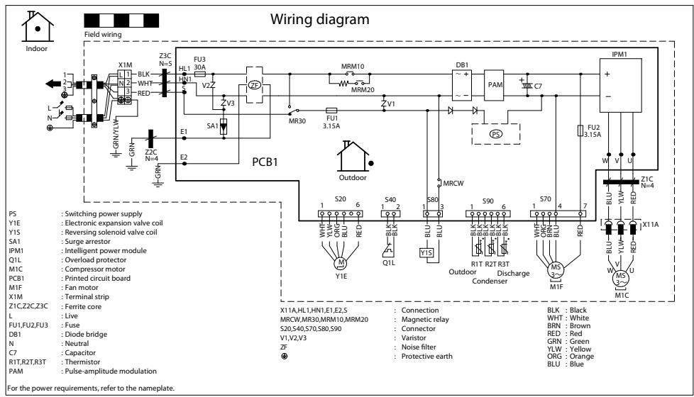
Figure 5-12: Wiring diagram - outdoor unit RXJ50M
3D090522A
5.3.2.7.RXM20-35M
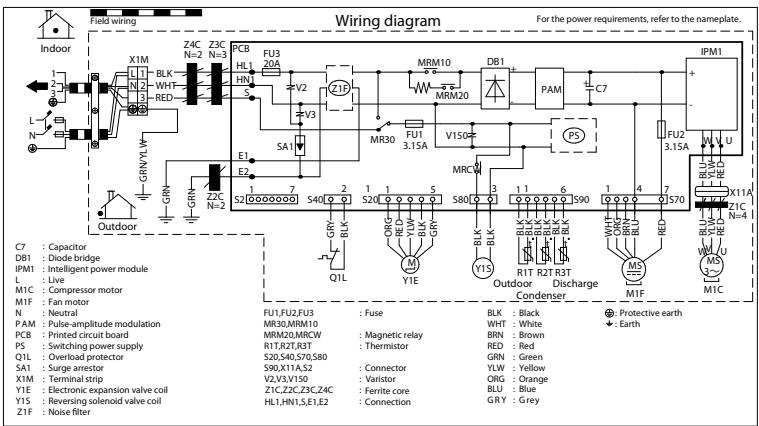
Figure 5-13: Wiring diagram - outdoor unit RXJ20-35M
4D099916B
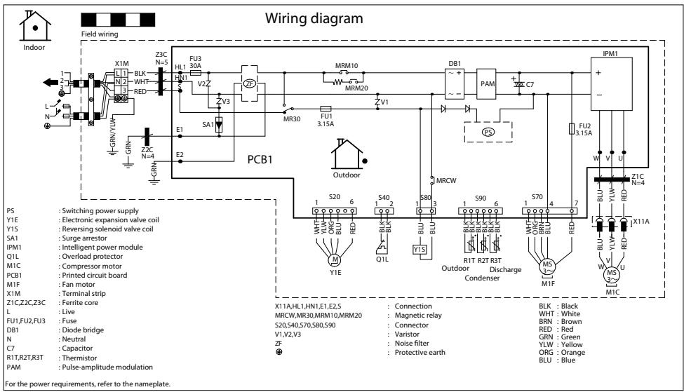
Figure 5-14: Wiring diagram - outdoor unit RXM42-50M
3D090522A
5.3.2.9.RXM60-71M
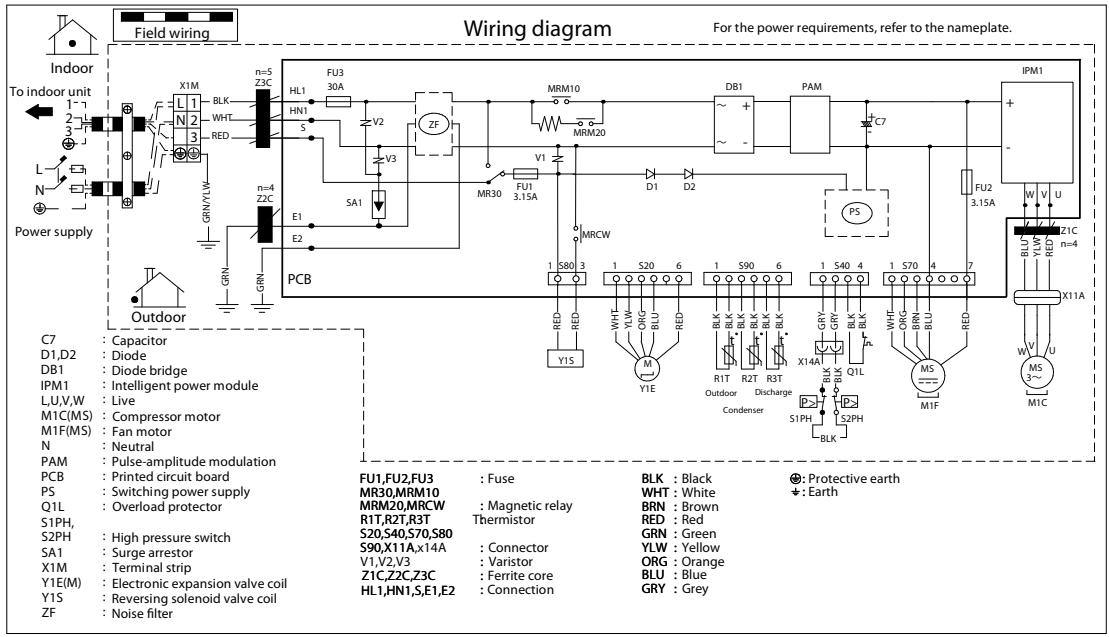
Figure 5-15: Wiring diagram - outdoor unit RXM60-71M
3D100894A
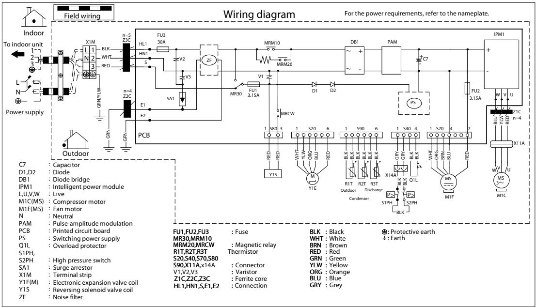
Figure 5-16: Wiring diagram - outdoor unit RXM71M
3D100894A
5.3.3. Field wiring
Not applicable.
5.4. Piping diagram
5.4.1. Indoor unit
Not applicable.
5.4.2. Outdoor unit
5.4.2.1. 2MXM40M
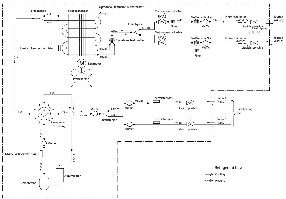
Figure 5-17: Piping diagram - outdoor unit 2MXM40M
5.4.2.2.3MXM68M
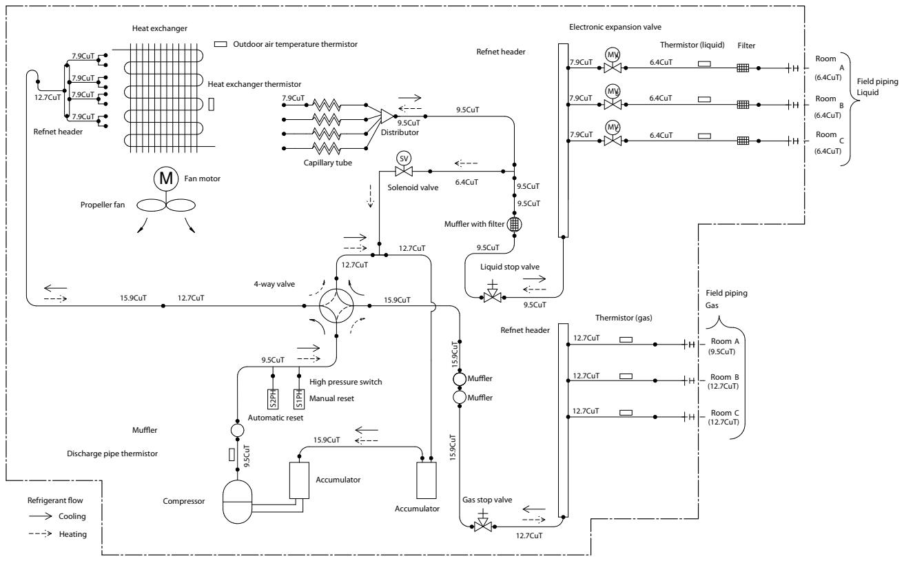
Figure 5-18: Piping diagram - outdoor unit 3MXM68M
5.4.2.3. 4MXM68M
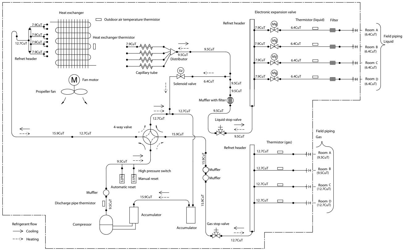
Figure 5-19: Piping diagram - outdoor unit 4XM68M
5.4.2.4. 5MXM-M
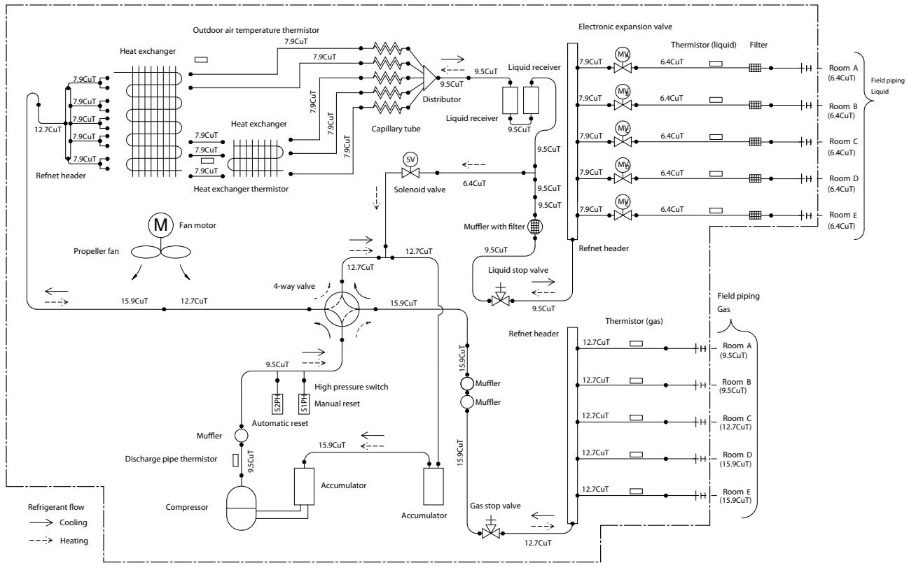
Figure 5-20: Piping diagram - outdoor unit 2MXM50M
5.4.2.5.RXJ20-35M
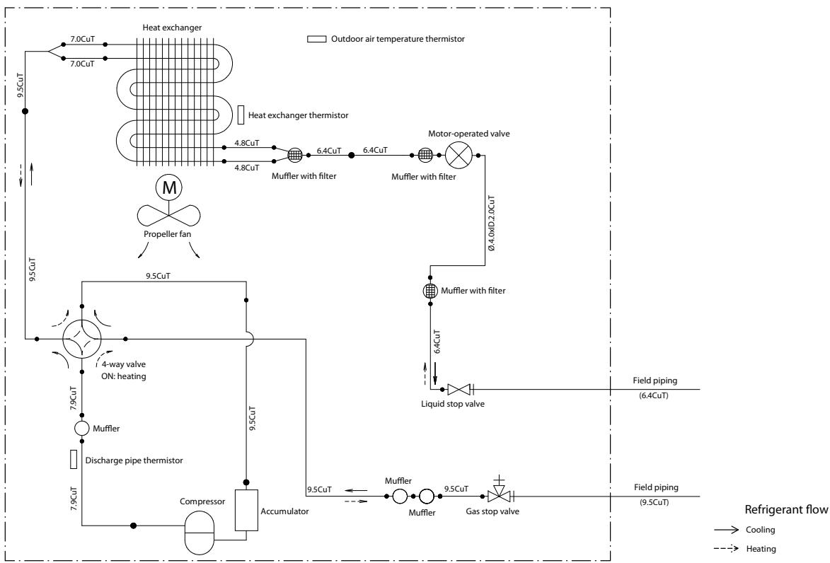
Figure 5-21: Piping diagram - outdoor unit RXJ20-35M
5.4.2.6.RXJ50M
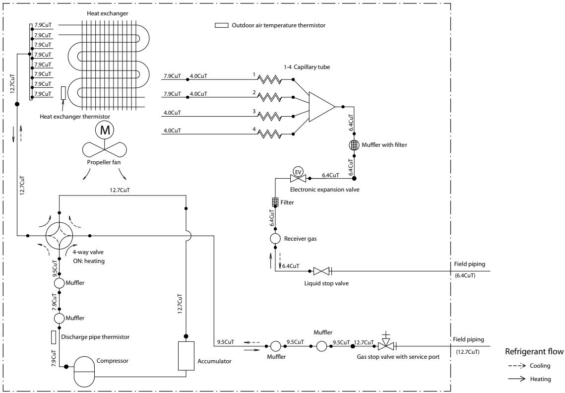
Figure 5-22: Piping diagram - outdoor unit RXJ50M
5.4.2.7.RXM20-35M
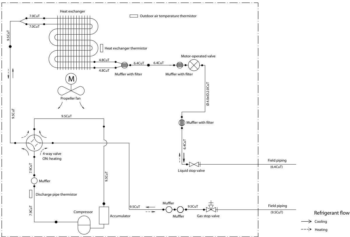
Figure 5-23: Piping diagram - outdoor unit RXJ20-35M
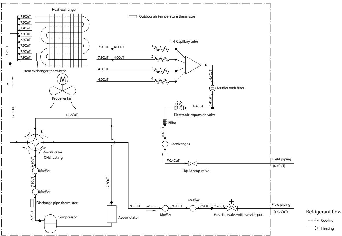
Figure 5-24: Piping diagram - outdoor unit RXM42-50M
5.4.2.9.RXM60
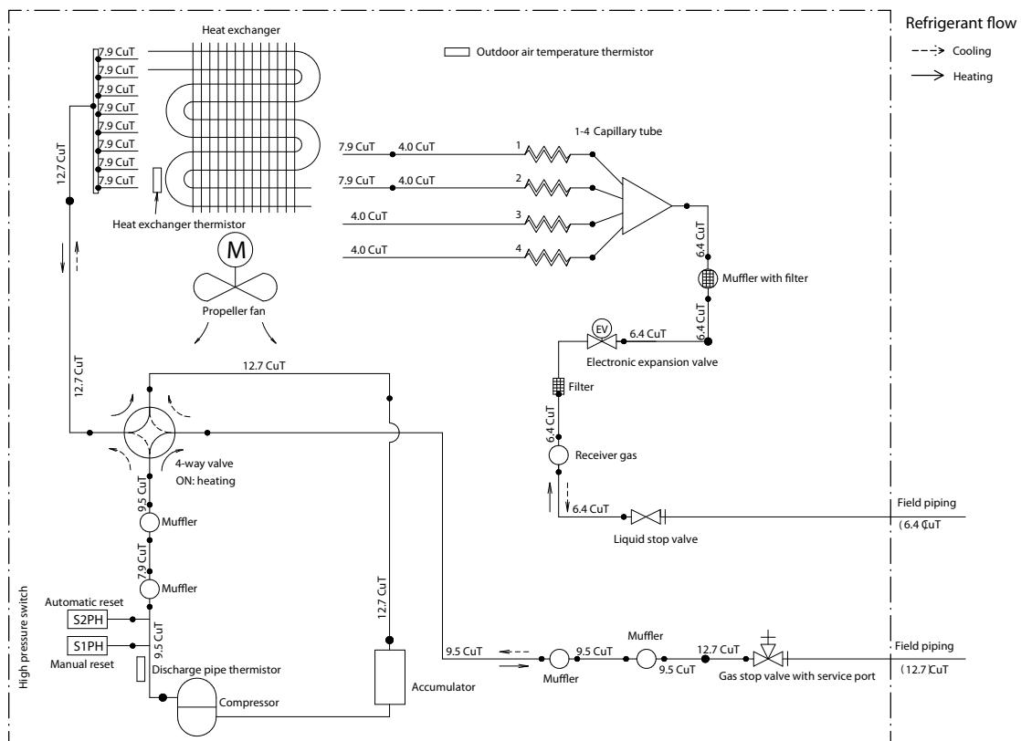
Figure 5-25: Piping diagram - outdoor unit RXM60
5.4.2.10.RXM71M
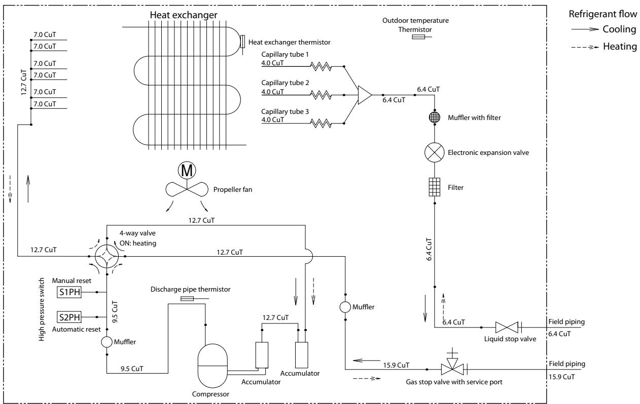
Figure 5-26: Piping diagram - outdoor unit RXM71M
5.5. Component overview of unit
5.5.1. Indoor unit
Not available yet.
5.5.2. Outdoor unit
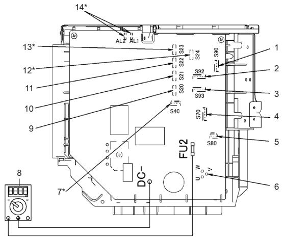
Figure 5-27: Component overview - outdoor unit
- Thermistor lead wire connector
- Thermistor lead wire connector (gas pipe)
- Thermistor lead wire connector (liquid pipe)
- Fan motor lead wire connector
- Four way valve lead wire connector
- Compressor lead wire connector
-
OL lead wire connector * high pressure switch
-
Multimeter (DC voltage range)
- Electronic expansion valve coil lead wire connection (room - A)
- Electronic expansion valve coil lead wire connection (room - B)
- Electronic expansion valve coil lead wire connection (room - C)
- Electronic expansion valve coil lead wire connection (room - E) *
- Electronic expansion valve coil lead wire connection (room - D) *
-
Solenoid valve lead wire connector *
-
may not be present depending on the model
5.6. Product specific information
5.6.1. Error codes
5.6.1.1. "E7-00" - Fan motor abnormality
Unit will automatically reset the error after a continuous run for 60 minutes without any other error code.
5.6.1.2. "EA-00" - Malfunction of 4-way valve
Set conditions
Room thermistor/indoor heat exchanger is not functioning within operation range.
Reset conditions
Continuous run for about 60 minutes without any other error.
5.6.1.3. "F3-00" - Discharge pipe temperature abnormality
Set conditions
If the discharge temperature detected is above A, the compressor stops.
Automatic reset conditions
Unit will automatically reset the error when the discharge temperature drops below B for 60 minutes without any other error.
| Compressor frequency (Hz) | A (°C) | B (°C) |
| >45 Hz and rising | 110 | 97 |
| >40 Hz and dropping | ||
| 30~45 Hz and rising | 105 | 92 |
| 25~40 Hz and dropping | ||
| <30 Hz and rising | 99 | 86 |
| <25 Hz and dropping |
5.6.1.4. "L3-00" - Switch box temperature abnormality
Set conditions
When the compressor is off, the radiation fin temperature is above 98°C .
Automatic reset conditions
Unit will automatically reset the error when the radiation fin temperature drops below 75°C for 60 minutes without any other error.
To cool the electrical components, the outdoor fan starts when the radiation fin temperature rises above 83°C and stops when it drops below 75°C .
5.6.1.5. "L4-00" - Inverter radiating fin temperature abnormality
Set conditions
When the compressor is ON, the radiation fin temperature is above 98°C .
If the error repeats, the system is shut down.
Automatic reset conditions
Unit will automatically reset the error when the radiation fin temperature drops below 78°C for 60 minutes without any other error.
5.6.2. Component checklist
Not available yet.
5.7. Switch box
5.7.1. Indoor unit
Not applicable.
5.7.2. Outdoor unit
Not available.
5.8. Field information report
See next page.
In case a problem occurred on the unit which could not be resolved by using the content of this service manual or in case you have a problem which could be resolved but of which the manufacturer should be notified, we advise you to contact your distributor.
To facilitate the investigation, additional information is required. Please fill out the following form before contacting your distributor.

DAIKIN
FIELD INFORMATION REPORT
| Key person info | |
| Name: | Company name: |
| Your contact details | |
| Phone number: | E-mail address: |
| Site address: | |
| Your reference: | Date of visit: |
| Claim info | |
| Title: | |
| Problem description: | |
| Error code: | Trouble date: |
| Problem frequency: | |
| Investigation steps done: | |
| Insert picture of the trouble. | |
| Current situation (solved, not solved, ...) | |
| Countermeasures taken: | |
| Comments and proposals: | |
| Part available for return (if applicable): | |
| Application info | |
| Application (house, apartment, office, ...) | |
| New project or refurbishment: | |
| Heat emitters (radiators / under floor heating / fan coils / ...) | |
| Hydraulic layout (simple schematic): | |
| Unit / Installation info | |
| Model name: | Serial number: |
| Installation / commissioning date: | Software version hydro PCB A1P: |
| Software version hydro PCB A5P: | |
| Software version user interface: | Software version outdoor PCB: |
| Minimum water volume: | Maximum water volume: |
| Brine composition and mixture: | |
| Brine freeze up temperature: | |
| Space heating control (leaving water temperature, room thermostat, ext. room thermostat): | |
| Space heating setpoint: | |
| Domestic hot water control (reheat only, schedule only, reheat + schedule): | |
| Domestic hot water setpoint: | |
| Provide pictures of the field settings overview (viewable on the user interface). | |
- SERVICE
- MANUAL
- RA R32 SPLIT
- MULTI SPLIT M-SERIES
- PART 1. INTRODUCTION 9
- PART 2. TROUBLESHOOTING 17
- PART 3. REPAIR 61
- PART 4. MAINTENANCE 89
- PART 5. APPENDIX 91
- PART 1. INTRODUCTION
- THIS PART CONTAINS THE FOLLOWING CHAPTERS
- VERSION LOG
- SAFETY PRECAUTIONS
- MEANING OF SYMBOLS
- 1.2.2.WARNINGS
- WARNING
- CAUTIONS
- CAUTION
- INFORMATION
- GENERAL OPERATION
- HOW TO USE
- INTERACTIVE INFORMATION FLOW
- PARTS OF THE BOOK
- THE INTRODUCTION CHAPTER
- THE TROUBLESHOOTING CHAPTER
- THE REPAIR CHAPTER
- THE MAINTENANCE CHAPTER
- APPENDICES
- CONTACT INFORMATION
- PART 2. TROUBLESHOOTING
- ERROR CODES CHECK
- ERROR CODES VIA REMOTE CONTROLLER
- GENERAL
- HOW TO RESET ERROR CODES
- HISTORY OF ERROR CODES
- ERROR CODES VIA OUTDOOR UNIT PCB
- HOW TO RETRIEVE ERROR CODES
- CONTENT OF RETRY
- ERROR BASED TROUBLESHOOTING
- OVERVIEW OF ERROR CODES
- INDOOR UNIT
- A1-00" - PCB ABNORMALITY
- A1-01" - PCB ABNORMALITY
- A5-00" - FREEZE-UP PROTECTION / HEATING PEAK CUT CONTROL
- A6-00" - FAN MOTOR ABNORMALITY
- MORE INFO
- C4-00" - LIQUID PIPE THERMISTOR FOR HEAT EXCHANGER ABNORMALITY
- C7-00" - FRONT PANEL OPEN/CLOSE FAULT
- C9-00" - SUCTION AIR THERMISTOR ABNORMALITY
- UH-00" - ANTI-ICING FUNCTION IN OTHER ROOM(S)
- OUTDOOR UNIT
- E1-00" - OUTDOOR UNIT PCB ABNORMALITY
- E3-00" - DISCHARGE PRESSURE ABNORMALITY
- E5-00" - COMPRESSOR MOTOR LOCK OR OVERHEATED
- E6-00" - COMPRESSOR MOTOR LOCK
- E7-00" - FAN MOTOR ABNORMALITY
- E8-00" - COMPRESSOR OVERCURRENT DETECTION
- EA-00" - 4-WAY VALVE ABNORMALITY
- F3-00" - DISCHARGE PIPE TEMPERATURE ABNORMALITY
- F6-00" - HIGH PRESSURE ABNORMALITY OR REFRIGERANT OVERCHARGE
- H0-00" - COMPRESSOR SENSOR SYSTEM ABNORMALITY
- H6-00" - POSITION DETECTION SENSOR ABNORMALITY
- H8-00" - COMPRESSOR INPUT (CT) SYSTEM ABNORMALITY
- H9-00" - OUTDOOR AIR TEMPERATURE THERMISTOR ABNORMALITY
- J3-00" - DISCHARGE PIPE THERMISTOR ABNORMALITY
- J5-00" - SUCTION PIPE THERMISTOR ABNORMALITY
- J6-00" - OUTDOOR HEAT EXCHANGER THERMISTOR ABNORMALITY
- J8-00" - LIQUID PIPE THERMISTOR ABNORMALITY
- J9-00" - GAS PIPE THERMISTOR ABNORMALITY
- L1-00" - OUTDOOR MAIN PCB ABNORMALITY
- L3-00" - SWITCH BOX TEMPERATURE ABNORMALITY
- L4-00" - INVERTER RADIATING FIN TEMPERATURE ABNORMALITY
- L5-00" - INVERTER INSTANTANEOUS OVERCURRENT (AC OUTPUT)
- P4-00” – RADIATING FIN TEMPERATURE SENSOR ABNORMALITY
- SYSTEM
- U0-00" - REFRIGERANT SHORTAGE
- U2-00" - POWER SUPPLY ABNORMALITY OR INSTANTANEOUS POWER FAILURE
- U4-00" - TRANSMISSION ABNORMALITY BETWEEN INDOOR UNIT AND OUTDOOR UNIT
- U7-00" - TRANSMISSION OUTDOOR UNIT-OUTDOOR UNIT ABNORMALITY
- UA-00" - IMPROPER COMBINATION OF INDOOR UNIT AND OUTDOOR UNIT
- UF-00" - WIRING AND PIPING MISMATCH
- OTHERS
- SYMPTOM BASED TROUBLESHOOTING
- COMPONENT CHECKLIST
- OVERVIEW OF COMPONENT CHECKLISTS
- FAN MOTOR
- PRELIMINARY ACTIONS
- PROCEDURE
- ELECTRICAL CHECK
- WARNING: RISK OF FIRE
- 4-WAY VALVE
- CAUTION - RISK OF LIQUID ENTERING THE COMPRESSOR
- DETERMINE THE POSITION OF THE 4-WAY VALVE
- COMPRESSOR
- MECHANICAL CHECK
- ELECTRONIC EXPANSION VALVE
- HIGH PRESSURE SENSOR
- CHECK 1
- CHECK 2
- CHECK 3
- MAIN PCB
- PRESSURE SENSOR
- REFRIGERANT THERMISTORS
- OTHER CAPACITY RANGE
- PART 3. REPAIR
- REFRIGERANT REPAIR PROCEDURES
- OVERVIEW
- REFRIGERANT PIPING HANDLING
- RECOVERY PROCEDURE
- OUTDOOR UNIT CASING
- REFRIGERANT PUMP DOWN
- WARNING: RISK OF EXPLOSION
- SMALL OUTDOOR UNIT
- LARGE OUTDOOR UNIT
- NOTE
- PIPING REPAIR PROCEDURES
- SERVICE TOOLS
- UNIT SPECIFIC REPAIR PROCEDURES
- BASIC REMOVAL
- 3.3.2.1.1 SINGLE FAN OUTDOOR UNIT
- 3.3.2.1.2 REMOVING REFRIGERANT CONNECTION COVER
- REMOVAL
- SCREW
- 3.3.2.1.3 REMOVING THE TOP PLATE
- 3.3.2.1.4 REMOVING THE FRONT PLATE
- 3.3.2.1.5 REMOVING THE COMPRESSOR SOUND INSULATION
- REPLACING SWITCH BOX
- INSTALLATION
- REPLACING 4-WAY VALVE BODY
- REPLACING 4-WAY VALVE COIL
- REPLACING COMPRESSOR
- REPLACING DC FAN MOTOR ASSEMBLY
- REPLACING EXPANSION VALVE BODY
- REPLACING EXPANSION VALVE MOTOR
- REPLACING MAIN PCB
- REPLACING PROPELLER FAN BLADE ASSEMBLY
- REPLACING THERMISTORS
- SETTING TEST MODE FOR INVERTER CHECKER
- 3.3.2.12.1 FOR 2MXM OUTDOOR UNITS
- ARC466 SERIES
- ARC452, ARC433 SERIES
- 3.3.2.12.2 FOR 3 TO 5 MXM OUTDOOR UNITS
- PART 4. MAINTENANCE
- GENERAL MAINTENANCE
- OPTIMAL OPERATION CONDITIONS
- CORRELATION OF AIR-CONDITIONER'S OPERATION STATUS, PRESSURE AND RUNNING CURRENT
- GENERAL MAINTENANCE OUTDOOR UNIT
- OUTDOOR UNIT COIL
- PART 5. APPENDIX
- FIELD SETTING
- INDOOR FAN CONTROL DURING THERMOSTAT OFF IN COOLING
- BRIGHTNESS SETTING OF MULTI-COLOURED LAMP OF THE INDOOR UNIT
- ON/OFF BUTTON ON THE INDOOR UNIT
- FACILITY SETTING FOR OUTDOOR SPLIT UNITS
- OTHER JUMPER SETTINGS
- MULTI SPLIT OUTDOOR
- 5.1.2.2.1 WIRING ERROR CHECK
- 5.1.2.2.2 DIP SWITCH SETTINGS
- 5.1.2.2.3 COOL MODE LOCK
- 5.1.2.2.4 MULTI SPLIT OUTDOOR JUMPER SETTINGS
- REMOTE CONTROLLER
- DETAILED INFORMATION SETTING MODE
- WIRING DIAGRAM
- 2MXM50M
- 3MXM68M
- 4MXM-M
- 5MXM-M
- 5.3.2.5.RXJ20-35M
- 5.3.2.6.RXJ50M
- 5.3.2.7.RXM20-35M
- 5.3.2.9.RXM60-71M
- FIELD WIRING
- PIPING DIAGRAM
- 2MXM40M
- 5.4.2.2.3MXM68M
- 4MXM68M
- 5.4.2.5.RXJ20-35M
- 5.4.2.6.RXJ50M
- 5.4.2.7.RXM20-35M
- 5.4.2.9.RXM60
- 5.4.2.10.RXM71M
- COMPONENT OVERVIEW OF UNIT
- PRODUCT SPECIFIC INFORMATION
- ERROR CODES
- EA-00" - MALFUNCTION OF 4-WAY VALVE
- SWITCH BOX
- FIELD INFORMATION REPORT
- DAIKIN
Marque : DAIKIN
Modèle : FTXS-G ECO PERFORMANCE
Catégorie : Climatiseur mural