
AR 5726 - Imprimante SHARP - Notice d'utilisation et mode d'emploi gratuit
Retrouvez gratuitement la notice de l'appareil AR 5726 SHARP au format PDF.

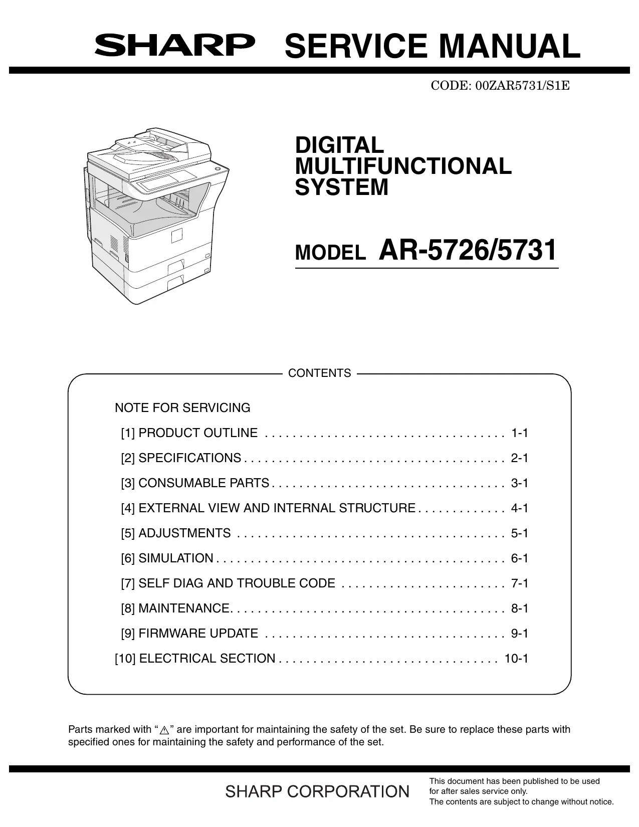

| Type de produit | Système multifonction numérique (imprimante, copieur, scanner, fax en option) |
| Modèle | AR-5726 (26 copies/min) / AR-5731 (31 copies/min) |
| Format de papier | A3, A4, A5, B4, B5, 11x17, 8.5x14, 8.5x11, 5.5x8.5, 8K, 16K, enveloppes |
| Capacité des bacs | Bac 1 : 500 feuilles (80g/m²), bac 2 : 500 feuilles, bac multifonction : 100 feuilles |
| Résolution d'écriture | 600 x 600 dpi, lissage 1200 dpi (équivalent) x 600 dpi |
| Première copie | Modèle 26 : 4,8 s (platen), modèle 31 : 4,5 s (platen) |
| Vitesse d'impression | Modèle 26 : jusqu'à 26 ppm (A4), modèle 31 : jusqu'à 31 ppm (A4) |
| Temps de préchauffage | Modèle 26 : ≤23 s, modèle 31 : ≤25 s |
| Mémoire vive | 32 Mo standard, extensible jusqu'à 1056 Mo |
| Dimensions (L x P x H) | Modèle OC : 623 x 628 x 668 mm ; modèle RSPF : 623 x 628 x 788 mm |
| Poids | Environ 46 kg |
| Alimentation électrique | 220 - 240 V, 8 A, 50/60 Hz |
| Consommation maximale | 1,45 kW |
| Fonctions de copie | Zoom 25-400%, recto-verso, assemblage électronique, mode livret, carte, marges, suppression des bords |
| Fonctions d'impression | SPLC, compatible Windows et Mac |
| Fonctions de numérisation | Résolution de lecture 400 x 600 dpi, chargeur automatique de documents (RSPF) jusqu'à 100 feuilles |
| Panneau de commande | Écran tactile LCD monochrome 8,1 pouces (640 x 240 pixels) |
| Consommables | Toner (cartouche) : MX-312GT/AT/FT, 33K pages ; Développeur : MX-312GV/AV/FV ; Tambour : MX-312GR/AR/FR |
| Pièces de maintenance | Kit rouleau chauffant supérieur (150K), kit rouleau chauffant inférieur (300K), kit PM 150K, unité MC, lame de nettoyage, unité de transfert |
| Sécurité | Mise à la terre obligatoire, protections contre les lasers et les hautes tensions, verrouillages de portes |
| Conditions d'utilisation | Température : 10-35°C, humidité : 20-85% HR, altitude : max 2000 m |
FOIRE AUX QUESTIONS - AR 5726 SHARP
Questions des utilisateurs sur AR 5726 SHARP
0 question sur cet appareil. Repondez a celles que vous connaissez ou posez la votre.
Poser une nouvelle question sur cet appareil
Téléchargez la notice de votre Imprimante au format PDF gratuitement ! Retrouvez votre notice AR 5726 - SHARP et reprennez votre appareil électronique en main. Sur cette page sont publiés tous les documents nécessaires à l'utilisation de votre appareil AR 5726 de la marque SHARP.
MODE D'EMPLOI AR 5726 SHARP
CODE: 00ZAR5731/S1E
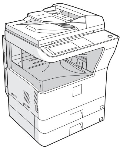
SYSTÈME MULTIFONCTION NUMÉRIQUE
MODÈLE AR-5726/5731
SOMMAIRE
NOTE POUR L'ENTRETIEN
[1] APERÇU DU PRODUIT 1-1 [2] SPÉCIFICATIONS 2-1 [3] PIÈCES CONSOMMABLES 3-1 [4] VUE EXTERNE ET STRUCTURE INTERNE 4-1 [5] RÉGLAGES 5-1 [6] SIMULATION 6-1 [7] AUTO-DIAGNOSTIC ET CODES D'ERREUR 7-1 [8] MAINTENANCE 8-1 [9] MISE À JOUR DU FIRMWARE 9-1 [10] SECTION ÉLECTRIQUE 10-1
Les pièces marquées d'un « » sont importantes pour la sécurité de l'appareil. Veillez à les remplacer par des pièces spécifiées afin de maintenir la sécurité et les performances de l'appareil.
SOMMAIRE
NOTE POUR L'ENTRETIEN
- Avertissement pour l'entretien.
- Précautions pour l'entretien
- Note pour la réparation/le remplacement du LSU
[1] APERÇU DU PRODUIT
- Gamme de machines et options 1-1
[2] SPÉCIFICATIONS
- Fonction de base 2-1
[3] PIÈCES CONSOMMABLES
- Tableau du système d'alimentation 3-1
- Liste des pièces de maintenance 3-2
- Définition de la fin de vie du développeur/tambour 3-3
- Identification du numéro de production 3-3
- Conditions environnementales 3-3
[4] VUE EXTERNE ET STRUCTURE INTERNE
- Vue externe 4-1
- Structure interne 4-2
- Panneau de commande 4-3 4. RSPF 4-4
- Capteur 4-5
- Interrupteur 4-5
- Électrovanne/Embrayage 4-6 8. Moteur d'entraînement 4-6 9. Lampe 4-7
- Ventilateur/Filtre 4-7 11. Carte de circuits imprimés 4-8
- Rouleau 4-8
[5] RÉGLAGES
- Liste des éléments de réglage. 5-1
- Détails des réglages. 5-1
[6] SIMULATION
- Généralités 6-1
- Liste des codes de simulation 6-3
- Détails de la simulation 6-6
[7] AUTODIAGNOSTIC ET CODES D'ANOMALIE
- Liste des codes d'anomalie 7-1
- Détails des codes d'anomalie 7-2
[8] MAINTENANCE
- Liste de maintenance 8-1
- Détails de la maintenance 8-3
- Autres éléments connexes 8-31
[9] MISE À JOUR DU FIRMWARE
- Procédure de mise à jour du firmware 9-1
[10] SECTION ÉLECTRIQUE
- Schéma fonctionnel 10-1
- Schéma de câblage réel 10-2
- Liste des signaux 10-9
NOTE POUR L'ENTRETIEN
Ce manuel d'entretien utilise des photographies pour garantir une opération sûre. Veuillez comprendre la signification des photographies avant d'effectuer l'entretien.
AVERTISSEMENT : Si cet AVERTISSEMENT est ignoré, un danger sérieux pour la vie ou une blessure grave peut en résulter. ATTENTION : Si cette ATTENTION est ignorée, une blessure ou des dommages matériels peuvent en résulter.
1. Avertissement pour l'entretien
1) Assurez-vous de brancher le cordon d'alimentation uniquement sur une prise de courant qui répond aux exigences de tension et de courant spécifiées. Évitez un câblage complexe, qui pourrait provoquer un incendie ou un choc électrique. 2) En cas d'anomalie telle que fumée ou odeur anormale, interrompez le travail et débranchez la fiche d'alimentation. Cela peut provoquer un incendie ou un choc électrique. 3) Assurez-vous que la machine est correctement mise à la terre. Un défaut de mise à la terre peut entraîner un choc électrique ou un incendie. Pour protéger la machine et l'unité d'alimentation contre la foudre, la mise à la terre doit être effectuée. 4) Lors du raccordement du fil de terre, ne le connectez jamais aux points suivants car cela pourrait provoquer une explosion, un incendie ou un choc électrique :
Tube à gaz, paratonnerre - Un tuyau d'eau ou un robinet qui n'est pas reconnu comme objet de mise à la terre par les autorités. - Fil de terre pour ligne téléphonique
5) N'endommagez pas, ne cassez pas ou ne sollicitez pas le cordon d'alimentation. Ne posez pas d'objets lourds sur le cordon d'alimentation. Ne pliez pas ou ne tirez pas le cordon avec force. Cela peut provoquer un incendie ou un choc électrique. 6) Tenez le câble d'alimentation éloigné d'une source de chaleur.
N'insérez pas la fiche d'alimentation avec de la poussière dessus dans une prise de courant. Cela peut provoquer un incendie ou un choc électrique.
7) Ne placez pas un récipient avec de l'eau ou un morceau de métal qui pourrait tomber à l'intérieur de la machine. Cela peut provoquer un incendie ou un choc électrique. 8) Ne touchez pas la fiche d'alimentation, n'insérez pas une prise téléphonique, n'effectuez pas d'entretien ou ne faites pas fonctionner la machine avec les mains mouillées ou huileuses. Cela peut provoquer un choc électrique.
2. Précautions de maintenance
1) Lors de la maintenance, débranchez la fiche d'alimentation, le câble d'imprimante, le câble réseau et la ligne téléphonique de la machine, sauf lors du test de communication, etc. Cela peut provoquer des blessures ou une électrocution. 2) Il y a une zone à haute température à l'intérieur de la machine. Soyez extrêmement prudent lors de la maintenance. 3) Il y a une section à haute tension à l'intérieur de la machine qui peut provoquer une électrocution. Soyez prudent lors de la maintenance. 4) Ne démontez pas l'unité laser. N'insérez pas de matériau réfléchissant tel qu'un tournevis dans le trajet du faisceau laser. Cela pourrait endommager les yeux par réflexion des faisceaux laser. 5) Lors de la maintenance de la machine en fonctionnement, veillez à ne pas entrer en contact avec les chaînes, les courroies, les engrenages et toute autre pièce mobile. 6) Ne laissez pas la machine avec le boîtier démonté. Ne permettez à aucune personne autre qu'un technicien de toucher l'intérieur de la machine. Cela pourrait provoquer une électrocution, une brûlure ou une blessure. 7) Lors de la maintenance, ne respirez pas excessivement le toner, le développateur et l'encre. Ne les mettez pas dans les yeux. Si du toner, du développateur ou de l'encre pénètre dans vos yeux, rincez-les immédiatement à l'eau et consultez un médecin si nécessaire. 8) La machine a des bords tranchants à l'intérieur. Soyez prudent pour ne pas vous blesser les doigts lors de la maintenance. 9) Ne jetez pas le toner ou une cartouche de toner au feu. Sinon, le toner pourrait éclater et vous brûler. 10) Lors du remplacement de la batterie au lithium sur la carte PWB, utilisez uniquement la batterie spécifiée. Si une batterie de spécifications différentes est utilisée, elle peut ne pas être compatible et provoquer une panne ou un dysfonctionnement de la machine. 11) Lors du transport d'une unité électrique ou d'une carte PWB, utilisez un sac antistatique (électricité). Le non-respect de cette consigne peut entraîner une défaillance des composants ou un dysfonctionnement de la machine.
3. Note pour la réparation/le remplacement du LSU
Lors de la réparation ou du remplacement, assurez-vous de respecter les points suivants.
1) Lors de la réparation ou du remplacement du LSU, assurez-vous de débrancher la fiche d'alimentation de la prise de courant. 2) Lors de la réparation ou du remplacement du LSU, suivez les procédures décrites dans ce manuel de service. 3) Lors de la vérification du fonctionnement après la réparation du LSU, gardez toutes les pièces, y compris le capot, installées et effectuez la vérification du fonctionnement. 4) Ne modifiez pas le LSU. 5) Lors de la vérification visuelle de l'intérieur de la machine pour le contrôle du fonctionnement, veillez à ne pas laisser les faisceaux laser pénétrer dans les yeux.
Si la précaution ci-dessus est négligée ou si un travail non désigné est effectué, la sécurité peut ne pas être assurée.
[1] APERÇU DU PRODUIT
1. Gamme de machines et options
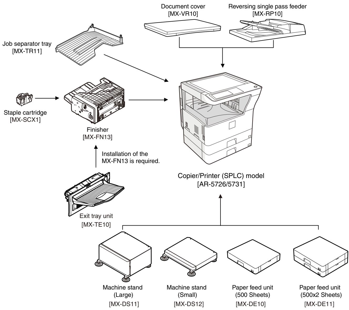
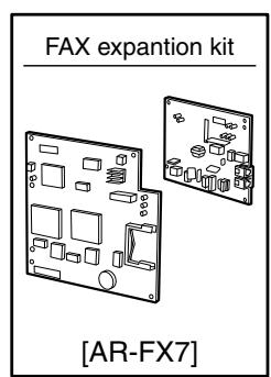
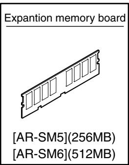
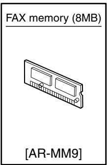
[2] SPÉCIFICATIONS
1. Fonction de base
A. Moteur de base
(1) Type
| Type | Desktop |
(2) Composition du moteur
| Photoconductor kind | OPC drum (Drum dia. 30mm) |
| Copying method | Electronic photo (Laser) |
| Developing system | Dry, 2-component magnetic brush development |
| Charging system | Sawtooth charging |
| Transfer system | Transfer roller system |
| Cleaning system | Contact blade system |
| Fusing system | Heat roller |
| Toner supply method | Toner supply by front cover open |
| Waste toner disposal | Toner cartridge collection |
(3) Dimensions / Poids
| External dimensions (W x D x H) | OC model: 623 x 628 x 668mm RSPF model: 623 x 628 x 788mm |
| Occupied dimensions (W x D) (when the manual paper feed tray is extended) | 898 x 628mm |
| Weight | About 46kg |
(4) Préchauffage
| Warm-up time | 23 sec or less (26-sheet model) 25 sec or less (31-sheet model) |
| Pre-heat | Yes |
| Jam recovery time | About 10sec, excluding fusing warmup, toner control, etc. |
Conditions : départ 60 secondes après ouverture du capot, conditions standard, arrêt du polygone.
(5) Temps de première copie
| 26-sheet model | 31-sheet model | |
| Platen | 4.8 sec | 4.5 sec |
| RSPF | 9.3 sec or less | |
- Conditions de mesure : lorsque le papier A4 ou 8,5" x 11" est chargé depuis le bac de la machine, avec rotation du polygone.
(6) Résolution moteur
| Writing resolution | 600 x 600dpi |
| Smoothing (Print) | 1200dpi (equivalent) x 600dpi |
| Gradation | Writing: Binary |
(7) Zone imprimable
| Max. print size | AB series: 416 x 293mm (600dpi: 9826dot x 6920dot) Inch series: 428 x 275mm (600dpi: 10110dot x 6496dot) |
| Void area image loss | Front/Rear: Less than 4mm Right/Left total: Less than 6mm at actual (100%) size |
(8) Vitesse moteur (ppm)
| Tray | Paper size | 26-sheet model | 31-sheet model |
| Tray 1-4 | A3 | 15 | 17 |
| B4/8.5 x 13 | 17 | 20 | |
| A4/B5/A5/8.5 x 11/5.5 x 8.5/16K | 26 | 31 | |
| A4R/8.5 x 11R/16KR | 18 | 24 | |
| B5R | 21 | ||
| 11 x 17 | 14 | 17 | |
| 8.5 x 14 | 16 | 20 | |
| 8K | 19 | ||
| Manual paper feed | A3 | 14 | 17 |
| 8.5 x 13 | 17 | 20 | |
| B4 | 16 | 19 | |
| A4/B5/A5/8.5 x 11/5.5 x 8.5/16K | 23 | 27 | |
| A4R/8.5 x 11R | 19 | 22 | |
| 16KR | 23 | ||
| B5R | 21 | 24 | |
| 11 x 17 | 14 | 16 | |
| 8.5 x 14 | 16 | 19 |
(9) Alimentation électrique
| Voltage/Current | 220 - 240V 8A |
| Frequency | 50/60Hz |
| Power source code | Inlet type |
| Power switch | 1 power source |
(10) Consommation électrique
| Maximum rated power consumption | 1.45kw |
| Shift time to sleep mode | Default (1 minute) |
(11) Mémoire
| Local Memory | Standard | 32MB |
| Expansion | 512MB x 2 | |
| Max. | 1056MB |
B. Carte contrôleur
(1) Carte contrôleur
| SPLC board | ||
| Interface | Ethernet | No |
| USB 2.0 Device | Full Speed 1slot | |
| Memory | No | |
| Memory expansion slot | --- | |
C. Panneau de commande
| Type | Dot matrix LCD, touch panel |
| Size | Monochrome H-VGA 8.1" |
| Display dot number | 640 x 240 (H-VGA) |
| LCD drive display area | 192 x 72mm |
| LCD backlight | Fluorescent lamp backlight system |
| LCD contrast adjustment | Yes |
D. Section scanner
(1) Résolution/Niveaux de gris
| Reading resolution (dpi) | Copy mode | ||||
| Platen | 400 x 600dpi | ||||
| RSPF | 400 x 600dpi | ||||
| Transmission resolution (dpi) | FAX transmission mode | ||||
| Select mode | Normal text | Fine text | Super fine text | Ultra fine text | |
| Input resolution: OC | 203.2 x 293.4 | 203.2 x 293.4 | 203.2 x 391.2 | 406.4 x 586.7 | |
| Input resolution: RSPF | 203.2 x 293.4 | 203.2 x 293.4 | 203.2 x 391.2 | 406.4 x 586.7 | |
| Transmission resolution | 203.2 x 97.8 | 203.2 x 195.6 | 203.2 x 391 | 406.4 x 391 | |
| Half tone | No | Yes | Yes | Yes | |
| Reading gradation | 256 gradations | ||||
| Exposure lamp | Electrodeless xenon lamp | ||||
| Output gradation | Binary | ||||
(2) Tableau de documents
| Type | Document table fixed type (Flat bed) | |
| Scanning area | 297 x 431.8mm | |
| Original standard position | Left bottom reference | |
| Detection | Yes | |
| Detection size | Inch series | Automatic setting 11 x 17, 8.5 x 14, 8.5 x 11, 8.5 x 11R, 5.5 x 8.5 Manual setting 11 x 17, 8.5 x 14, 8.5 x 13 (216 x 330), 8.5 x 11, 8.5 x 11R, 5.5 x 8.5, A3, A4, A4R |
| AB series | Automatic setting A3, B4, A4, A4R, A5 Manual setting 11 x 17, 8.5 x 14, 8.5 x 13 (216 x 330), 8.5 x 11, 8.5 x 11R, A3, B4, A4, A4R, A5 | |
(3) Chargeur automatique de documents
| Type | RSPF(Automatic duplex document feeder unit) | |
| Scan speed | When in single copy | When in duplex copy |
| Copy | 31-sheet model:27 sheets/min(400 x 600dpi)26-sheet model:26 sheets/min(400 x 600dpi) | 31-sheet model:13.6 side/min(400 x 600dpi)26-sheet model:13.6 side/min(400 x 600dpi) |
| Fax | 40 sheets/min(Normal text, A4R) | 17 sheets/min(Normal text, A4R) |
| Document set direction | Face-up reference | |
| Document standard position | Center reference | |
| Document transport system | Sheet through system | |
| Document size | AB series: A3 - A5Inch series: 11 x 17 - 5.5 x 8.5 | |
| Document weight | Single face: 35 - 128g/m2, 9 - 34 lbs,Duplex: 52 - 105g/m2, 13.9 - 28 lbs | |
| Max. loading capacity of documents | 100 sheets (90g/m2)Paper thickness of 13mm or less can be set. | |
| Transport disable document | OHP, perforated documents, photo,catalogue, second original sheet, tracingpaper, carbon paper, heat-sensitive paper,wrinkled paper, folded or broken paper,pasted or cut-away paper, documents ofmany perforated holes (2-hole, 3-holedocuments can be used), document printedby an ink ribbon | |
| Detection | Yes | |
| Detection size | Inchseries | Automatic setting11 x 17, 8.5 x 14, 8.5 x 11,8.5 x 11R, 5.5 x 8.5, A3, A4Manual setting11 x 17, 8.5 x 14, 8.5 x 13 (216 x330), 8.5 x 11, 8.5 x 11R,5.5 x 8.5, A3, A4, A4R |
| ABseries | Automatic setting11 x 17, 8.5 x 11, A3, B4, A4,A4R, B5, B5R, A5Manual setting11 x 17, 8.5 x 14, 8.5 x 13 (216 x330), 8.5 x 11, 8.5 x 11R, A3, B4,A4, A4R, A5 | |
| Multi copy | S-S, S-D, D-D, D-S | |
| Mixed paper feed | Enable (Same width only) | |
E. Section d'alimentation papier
| Type | Paper feed tray + Multi manual paper feed (Expanded up to 4 trays by installing options.) | |||
| Paper feed method | Paper is fed from the above by the front loading system. | |||
| Details of paper feed section | Tray1 | Tray2 | Manual paper feed tray | |
| Paper capacity | Standard paper (80g/m2) | 500 sheets | 100 sheets | |
| Paper size | A3, B4, A4, A4R, B5, B5R, A5, 11 x 17, 8.5 x 14, 8.5 x 13, 8.5 x 11, 8.5x11R, 5.5 x 8.5, 8K, 16K, 16KR | A3, B4, A4, A4R, B5R, 11 x 17, 8.5 x 14 (216 x 356), 8.5 x 13 (216 x 330), 8.5 x 11, 8.5 x 11R, 7.25 x 10.5R, 5.5 x 8.5, 8K, 16K, 16KR, A6R, Envelope*1 | A3, B4, A4, A4R, B5, B5R, A5R, A5, B6R, 11 x 17, 8.5 x 14 (216 x 356), 8.5 x 13 (216 x 330), 8.5 x 11, 8.5 x 11R, 7.25 x 10.5R, 5.5 x 8.5, 8K, 16K, 15KR, A6R, Envelope*1 | |
| Paper size detection | No | Yes | ||
| Allowable paper type and weight for paper feed | 56 - 105g/m2/15 - 28lbs Bond | Multi paper feed: Standard paper (56 - 128g/m2) Special paper, heavy paper (max. 200g/m2) Single paper feed: Standard paper, special paper, second original, heavy paper (max. 200g/m2), 56- 200g/m2 (14 - 54lbs) | ||
| Paper type | Standard paper (56 - 80g/m2) Normal paper (60 - 105g/m2) Letterhead Color paper | • Standard paper: 100 sheets (56 - 80g/m2) • Recycled paper/coarse paper: 100 sheets • Heavy paper (max. 200g/m2): 30 sheets • OHP/Label sheet/gift wrapping paper: 40 sheets • Label sheet: 40 sheets • Envelope (AB series: 10 sheets, Inch series: 5 sheets) | ||
| Paper size setting when shipping | Inch series | 8.5 x 11 | --- | |
| AB series | A4 | --- | ||
| Paper remaining detection | No (paper presence only) | |||
- 1 : Types d'enveloppes pris en charge : Commercial10 (4 - 1/8" x 9 - 1/2"), International DL (110 mm x 220 mm), International C5 (162 mm x 229 mm)
F. Section de sortie papier
(1) Bac central de l'unité principale
| Paper exit position/system | Main unit top surface face-down paper exit |
| Paper exit capacity | 500 sheets (A4, 8.5 x 11, 80g/m2paper) |
| Paper exit paper size/ kind | All kinds of paper which can be fed |
| Shifter function | Yes |
| Paper remaining detection for paper exit | Yes |
G. Fonctions de copie
(1) Taux de reproduction
| Copy magnification ratio | AB series | 25%, 50%, 70%, 81%, 86%, 100%, 115%, 122%, 141%, 200%, 400% |
| Inch series | 25%, 50%, 64%, 77%, 100%, 121%, 129%, 200%, 400% | |
| Zoom | 25 - 400% (Restriction by the document feeder unit: 50 - 200%) | |
(2) Processus de densité/qualité d'image de copie
| Exposure mode | Binary: Automatic, Text, Text/Photo, Photo |
| Number of manual steps | 5 steps |
(3) Recto-verso
| System | Switchback system |
| Paper size | A3, B4, A4, A4R, B5, B5R, A5, 11 x 17, 8.5 x 14, 8.5 x 13, 8.5 x 11, 8.5 x 11R |
| Type and weight of paper which can be passed | 56 - 105g/m2/15 - 21.3 lbs Bond Duplex print from manual paper feed can be made. (Except for heavy paper, OHP sheet, and other special paper) |
- Lorsque l'impression recto-verso est poursuivie à un certain niveau de température, la vitesse d'impression peut être réduite afin d'éviter une élévation anormale de la température dans la machine.
(4) Fonctions de copie
| Automatic paper selection |
| Automatic magnification ratio selection |
| Vertical/horizontal independent magnification ratio |
| Paper type selection |
| Auto tray switching |
| Rotation copy |
| Electronic sort |
| Job reservation (only during warm-up) |
| Program call-out/registration (10 items) |
| Preheat function |
| Auto power shut off function |
| User management (100 items) |
| Mixed documents feed (MIX only) |
| Binding margin (Left/Right/Upper) |
| Edge erase/Center erase (Center/Edge/Center + Edge) |
| 1 set 2 copy |
| Cover paper/Insert paper (Cover/Back cover only) |
| Multi shot (2 in 1/4 in 1) (Centering available) |
| Card shot (Centering available) |
| Pamphlet mode (Centering available) |
| Duplex copy direction switching |
| Large volume document mode |
| Black/white reverse (except for UK) |
| Stream feeding mode (ON/OFF switch by the system setting) |
H. Fonction imprimante
(1) Plateforme
| IBM PC/AT |
| Macintosh |
(2) Systèmes d'exploitation pris en charge
| OS | SPLC | |
| Windows | 2000 | Yes |
| XP | ||
| XP x64 | ||
| Server 2003 | No | |
| Server 2003 x64 | ||
| Vista | Yes | |
| Vista x64 | ||
| Server 2008 | No | |
| Server 2008 x64 | ||
| Mac | 9.0 - 9.2.2 | |
| X 10.2.8 | ||
| X 10.3.9 | ||
| X 10.4.11 | ||
| X 10.5 - 10.5.6 | ||
I. Conditions environnementales
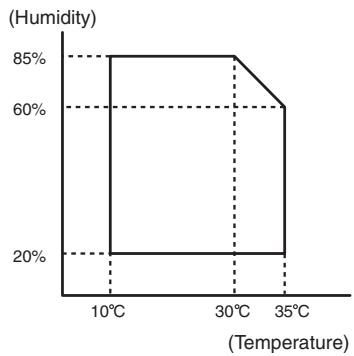
| Standard environmental conditions | Temperature | 20 - 25°C |
| Humidity | 65 ± 5%RH | |
| Usage environmental conditions | Temperature | 10 - 35°C |
| Humidity | 20 - 85%RH | |
| Atmospheric pressure | 590 - 1013 hPa (height: 0 - 2000m) |
[3] PIÈCES CONSOMMABLES
1. Tableau du système d'alimentation
A. Europe de l'Est/Russie
| No. | Item | Content | Life | Model name | Remarks |
| 1 | Toner cartridge (black) | Toner cartridge (With IC chip) ×1 (Toner; Net 700g) | 33K | MX-312GT | Life setting by A4 (8.5"×11") 6% document Default: Toner save mode |
| 2 | Developer (black) | Developer ×1 (Developer; Net 300g) | 26cpm: 75K 31cpm: 100K | MX-312GV | |
| 3 | Drum | Drum ×1 | 26cpm: 75K 31cpm: 100K | MX-312GR |
B. Filiales asiatiques
| No. | Item | Content | Life | Model name | Remarks |
| 1 | Toner cartridge (black) | Toner cartridge (With IC chip) ×1 (Toner; Net 700g) | 33K | MX-312AT | Life setting by A4 (8.5"×11") 6% document Default: Toner save mode |
| 2 | Developer (black) | Developer ×1 (Developer; Net 300g) | 26cpm: 75K 31cpm: 100K | MX-312AV | |
| 3 | Drum | Drum ×1 | 26cpm: 75K 31cpm: 100K | MX-312AR |
C. SMEF/Agent
| No. | Item | Content | Life | Model name | Remarks |
| 1 | Toner cartridge (black) | Toner cartridge (With IC chip) ×1 (Toner; Net 700g) | 33K | MX-312FT | Life setting by A4 (8.5"×11") 6% document Default: Toner save mode |
| 2 | Developer (black) | Developer ×1 (Developer; Net 300g) | 26cpm: 75K 31cpm: 100K | MX-312FV | |
| 3 | Drum | Drum ×1 | 26cpm: 75K 31cpm: 100K | MX-312FR |
2. Liste des pièces de maintenance
A. Europe de l'Est/Russie/SMEF
| No. | Item | Content | Life | Model name | Remarks |
| 1 | Upper heat roller kit | Upper heat roller ×1 | 150K | AR-310UH | |
| Fuser gear ×1 | |||||
| Upper heat roller bearing ×2 | |||||
| Upper cleaning pad ×1 | |||||
| Fusing separation pawl (upper) ×4 | |||||
| Thermistor cleaning pad ×2 | |||||
| 2 | Lower heat roller kit | Lower heat roller ×1 | 300K | MX-311LH | |
| Fusing separation pawl (lower) ×4 | |||||
| Fuser bearing (lower) ×2 | |||||
| 3 | 150K PM kit | Drum separation pawl unit ×2 | 150K | MX-311KA | |
| Transfer roller unit ×1 | |||||
| DV blade ×1 | |||||
| DV side sheet F ×1 | |||||
| DV side sheet R ×1 | |||||
| Toner filter unit ×1 | |||||
| 4 | MC unit | MC unit ×10 | 26cpm: 75K (×10) | MX-311MC | |
| 31cpm: 100K (×10) | |||||
| 5 | Cleaner blade | Cleaner blade ×10 | 26cpm: 75K (×10) | MX-311CB | |
| 31cpm: 100K (×10) | |||||
| 6 | Drum frame unit | Drum frame unit ×1 | 26cpm: 225K | MX-311DU | * The life of the toner reception seat attached to the drum frame is 300K, and it can be used up to 3 times. (Supplied as a drum frame unit.) |
| 31cpm: 300K | |||||
| 7 | Transfer roller unit | Transfer roller unit ×1 | 150K | MX-311TX | |
| 8 | Staple cartridge | Staple cartridge ×3 | 5000 staples ×3 | MX-SCX1 |
- Les autres pièces de maintenance que celles ci-dessus sont fournies comme pièces de service.
B. Filiales asiatiques/Agent
| No. | Item | Content | Life | Model name | Remarks |
| 1 | Upper heat roller kit | Upper heat roller x1 | 150K | AR-310UH | |
| Fuser gear x1 | |||||
| Upper heat roller bearing x2 | |||||
| Upper cleaning pad x1 | |||||
| Fusing separation pawl (upper) x4 | |||||
| Thermistor cleaning pad x2 | |||||
| 2 | Lower heat roller kit | Lower heat roller x1 | 300K | MX-311LH | |
| Fusing separation pawl (lower) x4 | |||||
| Fuser bearing (lower) x2 | |||||
| 3 | 150K PM kit | Drum separation pawl unit x2 | 150K | MX-311KA | |
| Transfer roller unit x1 | |||||
| DV blade x1 | |||||
| DV side sheet F x1 | |||||
| DV side sheet R x1 | |||||
| Toner filter unit x1 | |||||
| 4 | MC unit | MC unit x10 | 26cpm: 75K (×10) | MX-311MC | |
| 31cpm: 100K (×10) | |||||
| 5 | Cleaner blade | Cleaner blade x10 | 26cpm: 75K (×10) | MX-311CB | |
| 31cpm: 100K (×10) | |||||
| 6 | Drum frame unit | Drum frame unit x1 | 26cpm: 225K | MX-311DU | * The life of the toner reception seat attached to the drum frame is 300K, and it can be used up to 3 times. (Supplied as a drum frame unit.) |
| 31cpm: 300K | |||||
| 7 | Staple cartridge | Staple cartridge x3 | 5000 staples x3 | MX-SCX1 |
- Les autres pièces de maintenance que celles ci-dessus sont fournies comme pièces de service.
3. Définition de la fin de vie du développeur/tambour
Lorsque le compteur du développeur/tambour atteint le niveau spécifié.
Lorsque le régime du développeur/tambour atteint le niveau spécifié.
Lorsque l'une ou l'autre des conditions ci-dessus est atteinte, la fin de vie est jugée.
Dans un cas réel, lors des opérations de correction ou de préchauffage, ainsi que lors de l'opération de sortie, le développeur et le tambour tournent.
Par conséquent, le niveau de consommation du tambour et du développeur ne peut pas être déterminé uniquement par la quantité de copies/impressions. Ainsi, lorsque le régime (rpm) atteint le niveau spécifié, il est jugé comme étant en fin de vie.
Pour vérifier la durée de vie du tambour et du développeur, utilisez SIM22-1.
| Developer/drum counter | Number of rotations (Rotations) | ||
| Developer/drum | 26cpm model | 31cpm model | 550K |
| 75K | 100K | ||
4. Identification du numéro de production
L'étiquette sur la cartouche de toner indique la date de production.
Lieu de production (1 chiffre)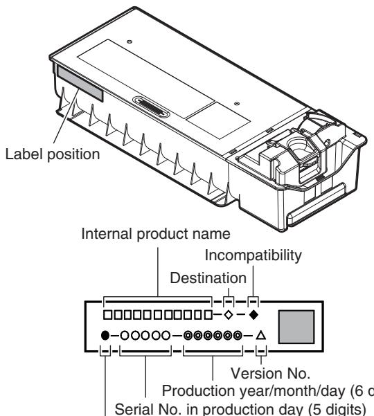
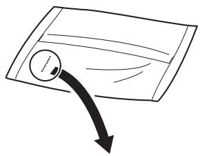
| 1 | 2 | 3 | 4 | 5 | 6 | 7 | 8 |
Le numéro de lot est composé de 8 chiffres. Chaque chiffre indique le contenu comme suit. Le numéro est imprimé en bas à droite de la surface arrière du sac de développeur.
1 Alphabet Indique l'usine de production. 2 Chiffre Indique l'année de production. 3,4 Chiffres Indiquent le mois de production. 5,6 Chiffres Indiquent le jour de production. 7 Tiret 8 Chiffre Indique le lot de production.
L'impression laser indique le code de conformité du modèle et la date (année, mois, jour) de production.
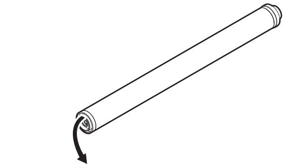
| 1 | 2 | 3 | 4 | 5 |
1 Alphabet Indique le code de conformité du modèle. L pour ce modèle. 2 Chiffre Indique le dernier chiffre de l'année de production. 3 Chiffre ou X, Y, Z Indique le mois de l'emballage. X représente octobre, Y novembre, et Z décembre. 4,5 Chiffres Indiquent le jour du mois de l'emballage.
5. Conditions environnementales
(Température)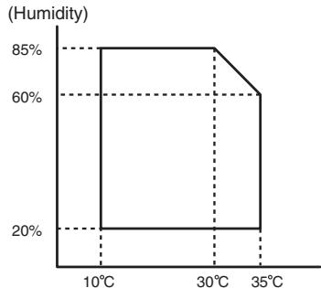
| Standard environmental conditions | Temperature | 20 - 25°C |
| Humidity | 65 ± 5%RH | |
| Usage environmental conditions | Temperature | 10 - 35°C |
| Humidity | 20 - 85%RH | |
| Atmospheric pressure | 590 - 1013 hPa (height: 0 - 2000m) | |
| Storage period | Toner/Developer: 24 months from the manufactured month (Production lot) under unsealed state Drum: 36 months from the manufactured month under unsealed state | |
[4] VUE EXTERNE ET STRUCTURE INTERNE
1. Vue externe
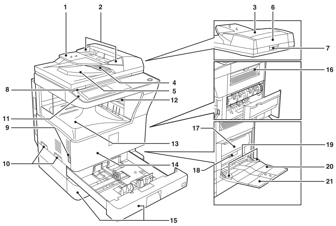
| No. | Name | Function/Operation |
| 1 | Document feeder tray | Place the original(s) that you wish to scan face up here. |
| 2 | Original guides | Adjust to the size of the originals. |
| 3 | Document feeder cover | Open to remove misfed originals. |
| 4 | Reversing tray | Pull out to remove misfed originals. |
| 5 | Exit area | Originals exit the machine here after copying. |
| 6 | Document transport cover | Open to remove misfed originals. |
| 7 | Document transport cover knob | Pull to open the document transport cover. |
| 8 | Document glass | Place an original that you wish to scan face down here. |
| 9 | Power switch | Press to turn the machine power on and off. |
| 10 | Handles | Use to move the machine. |
| 11 | Operation panel | Contains operation keys and the touch panel. |
| 12 | Job separator tray (Upper tray) (optional) | Print jobs and received faxes are delivered to this tray. |
| 13 | Center tray | Finished copies are delivered to the center tray. |
| 14 | Front cover | Open to remove paper misfeeds and perform machine maintenance. |
| 15 | Paper trays | Each tray holds 500 sheets of copy paper. |
| 16 | Upper right side cover | Open to remove misfeeds when an optional job separator tray kit or a optional finisher is installed. |
| 17 | Side cover | Open to remove misfeeds. |
| 18 | Side cover handle | Pull to open the side cover. |
| 19 | Bypass tray paper guides | Adjust to the width of the paper. |
| 20 | Bypass tray | Regular paper and special paper (such as transparency film) can be fed from the bypass tray. |
| 21 | Bypass tray extension | Pull out the bypass tray extension before placing paper in the bypass tray. |
2. Structure interne
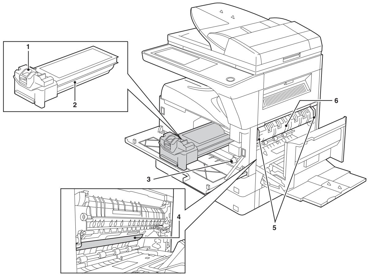
| No. | Name | Function/Operation | Note |
| 1 | Toner cartridge lock release lever | Use to unlock the toner cartridge. | |
| 2 | Toner cartridge | Contains toner. | |
| 3 | Roller rotating knob | Turn to remove misfed paper. | |
| 4 | Photoconductive drum | Copy images are formed on the photoconductive drum. | Do not touch the photoconductive drum (green portion). Doing so may damage the drum and cause smudges on copies. |
| 5 | Fusing unit release levers | To remove a paper misfeed in the fusing unit, push up on these levers and remove the paper. | The fusing unit is hot. Do not touch the fusing unit when removing misfed paper. Doing so may cause a burn or injury. |
| 6 | Fusing unit paper guide | Open to remove misfed paper. |
3. Panneau de commande
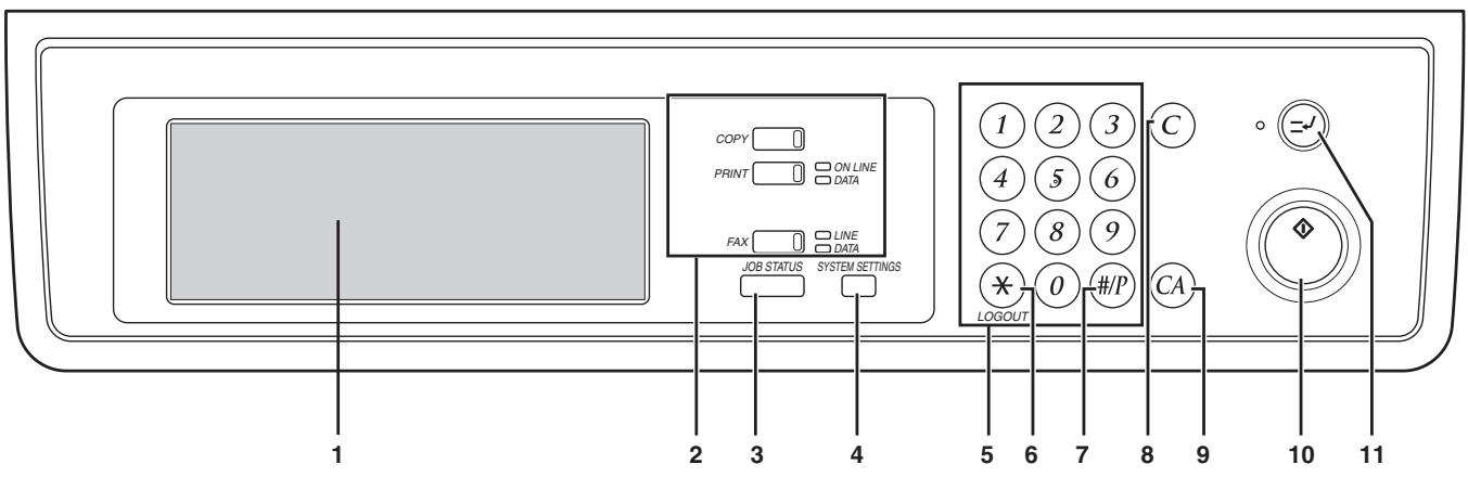
| No. | Name | Function/Operation | Note |
| 1 | Touch panel | The machine status, messages and touch keys are displayed on the panel. The display will show the status of printing, copying or network scanning according to the mode that is selected. For details see the next page. | |
| 2 | Mode select keys and indicators | Use to change modes and the corresponding display on the touch panel. | |
| [COPY] key | Press to select copy mode. | ||
| [PRINT] key/ONLINE indicator/DATA indicator | [PRINT] key: Press to select print mode. • ONLINE indicator: Print jobs can be received when this indicator is lit. • DATA indicator: A print job is in memory. The indicator lights steadily while the job is held in memory, and blinks while the job is printed. | ||
| [FAX] key/LINE indicator/DATA indicator | [FAX] key: Press to select fax mode when the fax option is installed. • LINE indicator: This lights up while faxes are being sent or received. • DATA indicator: Blinks when a fax has been received to memory and lights steadily when a fax is waiting in memory for transmission. | When the fax option is installed. | |
| 3 | [JOB STATUS] key | Press to display the current job status. | |
| 4 | [SYSTEM SETTINGS] key | Use to adjust various settings of the machine including the contrast of the touch panel and administrator settings. | |
| 5 | Numeric keys | Use to enter numeric values for various settings. | |
| 6 | [LOGOUT] key (⊗) | When auditing mode is enabled, press this key after finishing a job to return the machine to account number entry standby. | |
| 7 | [#/P] key (⊕) | Use this key to execute a job program in copy mode. The key is also used to dial in fax mode. | |
| 8 | [CLEAR] key (◎) | Press to clear a copy number setting or cancel a job. | |
| 9 | [CLEAR ALL] key (⊕) | Reset the settings to the initial settings. | |
| 10 | [START] key (⊗) | Press in copy mode, scanner mode, or fax mode to begin copying, network scanning, or faxing. This key blinks when auto power shut mode has activated. Press the key to return to normal operation. | |
| 11 | [INTERRUPT] key (⊗) | Use to perform an interrupt copy job. |
4. RSPF
A. Vue externe
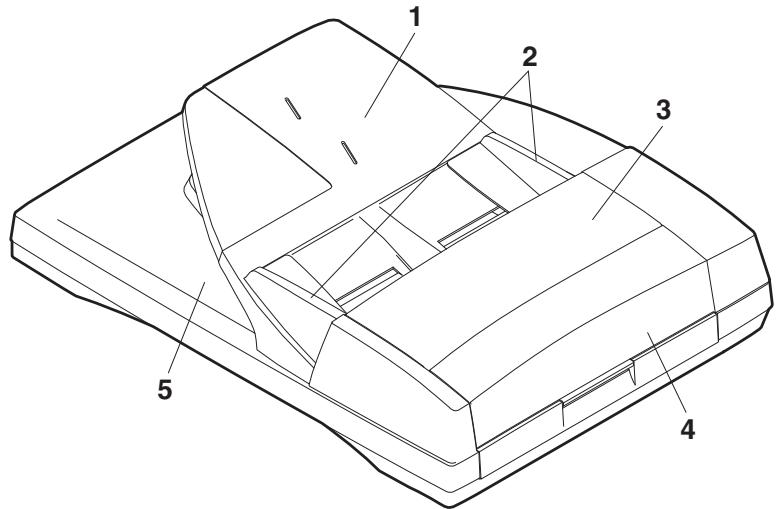
| No. | Name |
| 1 | Document set tray |
| 2 | Document guide |
| 3 | Document feed section cover |
| 4 | Document transport section cover |
| 5 | Document exit section |
B. Structure interne
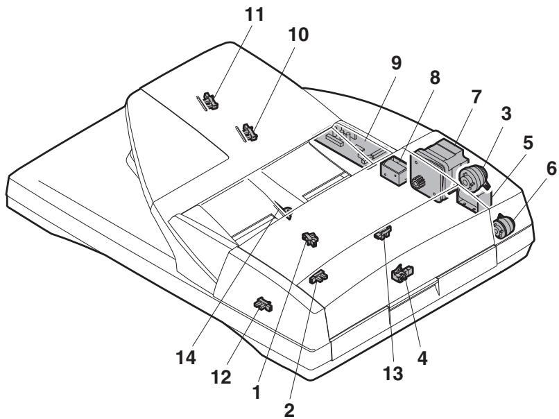
| No. | Code | Name | Type | Function/Operation |
| 1 | EMPS | Document set sensor | Photo transmission | Detects presence of documents. |
| 2 | FGOD | Open/close sensor | Photo transmission | Detects open/close of the paper feed unit. |
| 3 | DFCL | Paper feed clutch | — | — |
| 4 | DFD | Paper entry sensor | Photo transmission | Detects presence of documents. |
| 5 | RSOL | Pressure release solenoid | — | — |
| 6 | CLH | Transport clutch | — | — |
| 7 | DTM | SPF motor | Stepping motor | Drives document feed on the tray, transport, and paper exit roller. |
| 8 | GSOL | Gate solenoid | — | — |
| 9 | — | Interface PWB | — | — |
| 10 | DLS1 | Document length detection SW (Short) | Photo transmission | Detects the document length on the tray. |
| 11 | DLS2 | Document length detection SW (Long) | Photo transmission | Detects the document length on the tray. |
| 12 | OPCLS | Book sensor | Photo transmission | Detects the SPF float. |
| 13 | RDD | Paper exit sensor | Photo transmission | Detects presence of documents. |
| 14 | SWD | Document width sensor | Volume | Detects the document width on the tray. |
5. Capteur
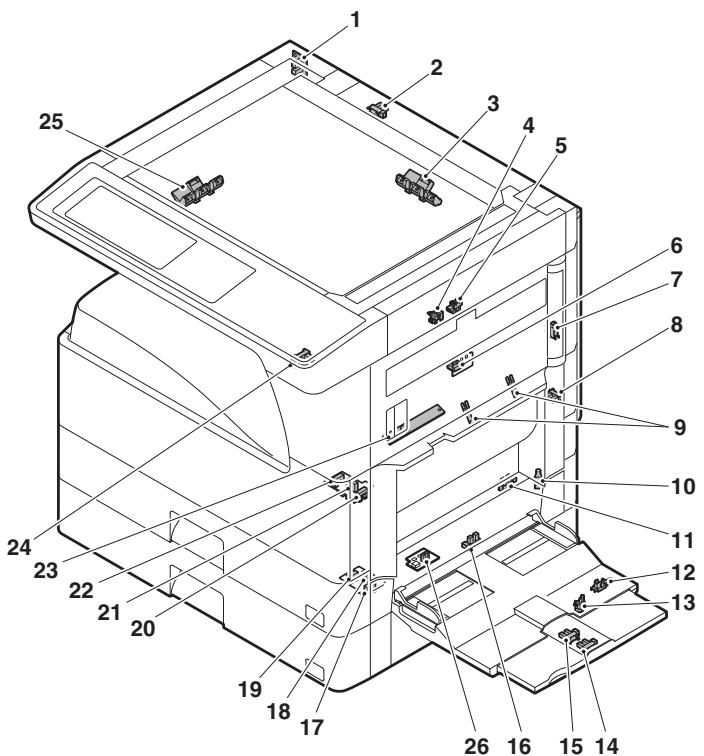
| No. | Name | Code | Function and operation |
| 1 | Mirror home position sensor | MHPS | Mirror (scatterer) home position detection |
| 2 | Document cover sensor | OCSW | Document cover open/close detection |
| 3 | Document size sensor | DSIN3 | Document size detection (Inch series: PD3, 4) (AB series: PD4, 5) |
| 4 | 2nd paper exit sensor (Option) | POD2 | 2nd paper exit detection |
| 5 | 2nd paper exit full detection sensor (Option) | TOPF | 2nd paper exit section full detection |
| 6 | 1st paper exit sensor | POD1 | 1st paper exit detection |
| 7 | Shifter home position sensor (Except North America) | SFTHP | Shifter home position sensor detection |
| 8 | Paper exit sensor (DUP side) | PPD2 | Paper exit detection |
| 9 | Thermistor | Fusing temperature detection | |
| 10 | 1st tray (paper tray) detection | CD1 | 1st tray (paper tray) empty detection |
| 11 | Manual feed paper entry sensor | PPD1L | Sensor of paper entry from the manual paper feed tray, the 2nd/multi-tray desk, or the DUP |
| 12 | Manual paper feed tray empty sensor 2 | MPLS2 | Manual feed tray position detection |
| 13 | Manual paper feed tray empty sensor 1 | MPLS1 | Manual feed tray position detection |
| 14 | Manual feed length detection sensor 1 | MPLD1 | Manual feed paper length detection |
| 15 | Manual feed length detection sensor 2 | MPLD2 | Manual feed paper length detection |
| 16 | Manual feed paper empty sensor | MPED | Manual feed paper empty detection |
| 17 | 2nd tray paper pass sensor | PFD2 | 2nd tray paper pass |
| No. | Name | Code | Function and operation |
| 18 | 2nd tray paper upper limit detection sensor | LUD2 | 2nd tray paper upper limit detection |
| 19 | 2nd tray paper empty sensor | PED2 | 2nd tray paper empty detection |
| 20 | 1st tray paper pass sensor | PPD1H | 1st tray paper pass |
| 21 | 1st tray paper upper limit detection sensor | LUD1 | 1st tray paper upper limit detection |
| 22 | 1st tray paper empty sensor | PED1 | 1st tray paper empty detection |
| 23 | Toner sensor | Toner density detection | |
| 24 | Center tray paper YES/NO sensor | LOEMP | Center tray paper YES/NO detection |
| 25 | Document size sensor | DSINO | Document size detection (Inch series: PD1, 2) (AB series: PD1 - 3) |
| 26 | Reverse pass paper detection sensor | DUP2 | Reverse pass detection |
6. Interrupteur
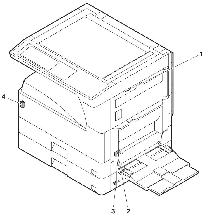
| No. | Name | Code | Function and operation |
| 1 | Right cabinet door switch (Option) | DSWR0 | Right cabinet door open/close detection |
| 2 | Door switch | DSWR1 | Front door and side door open/close detection |
| 3 | 2nd right door switch | DSWR2 | Side door open/close detection |
| 4 | Main switch | PSSW | Main power switch |
7. Électrovanne/Embrayage
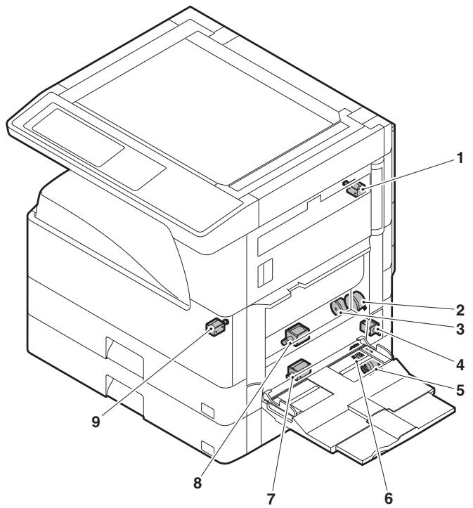
| No. | Name | Code | Function and operation |
| 1 | Paper exit gate switching solenoid (Option) | OGS | Paper exit gate switcher |
| 2 | PS clutch | RRC | Main unit paper feed |
| 3 | Paper feed clutch | CPFS1 | Paper feed roller drive |
| 4 | Manual paper feed solenoid | MPFS | Manual paper feed solenoid |
| 5 | Paper feed transfer clutch | TRC2 | Paper feed transfer clutch |
| 6 | 2nd tray paper feed clutch | CPFS2 | |
| 7 | 2nd tray paper feed solenoid | CPFC2 | Solenoid for the paper feed from the tray |
| 8 | Paper feed solenoid | CPFC1 | Solenoid for the paper feed from the tray |
| 9 | Separation pawl solenoid | PSPS | Separation pawl operation solenoid |
8. Moteur d'entraînement
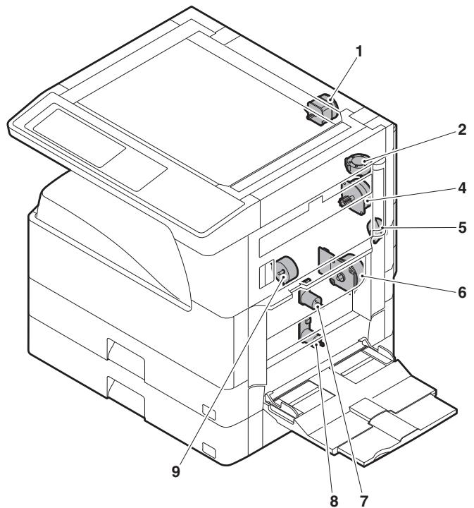
| No. | Name | Code | Function and operation |
| 1 | Mirror motor | MIRM | Optical mirror base drive |
| 2 | Shifter motor(Except North America) | SFTM | Shifter drive |
| 4 | Duplex motor | DPXM | Duplex paper switching and exit motor |
| 5 | DUP-2 motor | Reverse pass for paper transport | |
| 6 | Main motor | MM | Main drive |
| 7 | Tray lift-up motor | LUM1 | Tray paper lift-up |
| 8 | Tray lift-up motor | LUM2 | Tray paper lift-up |
| 9 | Toner motor | TM | Toner supply |
9. Lampe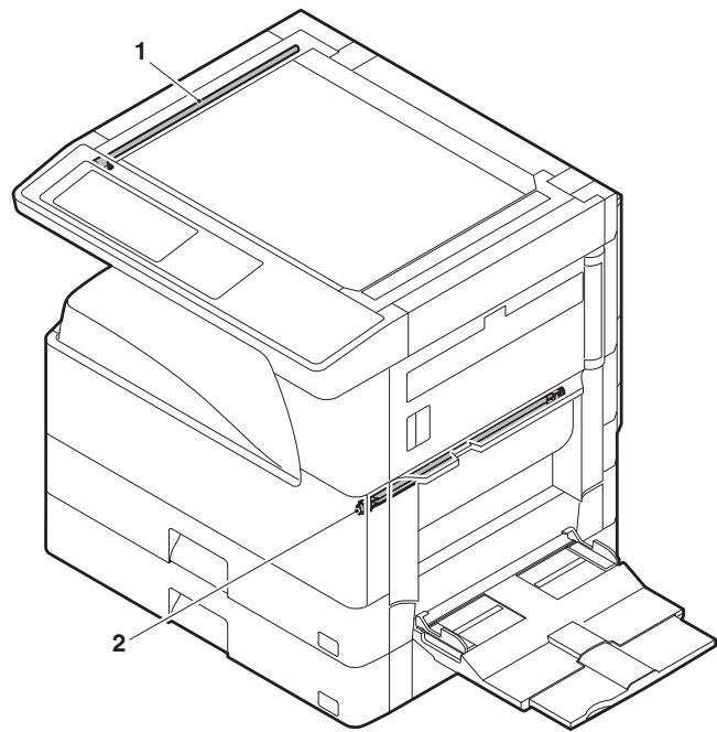
| No. | Name | Function and operation |
| 1 | Copy lamp | Image radiation lamp |
| 2 | Heater lamp | Fusing heat lamp |
10. Ventilateur/Filtre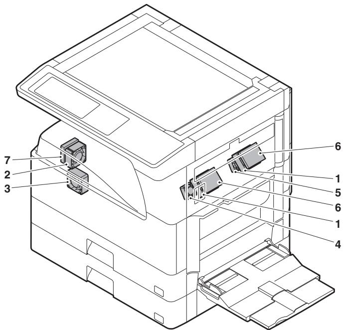
| No. | Name | Code | Function and operation |
| 1 | Cooling fan | VFM | Cools the inside of the unit. |
| 2 | Exhaust fan motor | DCFM | Cools the inside of the unit. |
| 3 | Intake fan motor | DCFM2 | Cools the inside of the unit. |
| 4 | Fusing paper exit fan | VFM2 | Cools the inside of the unit. (31 sheet model) |
| 5 | Fusing paper exit fan | VFM2 | Cools the inside of the unit. |
| 6 | Ozon filter | ||
| 7 | Ozon filter |
11. Carte de circuit imprimé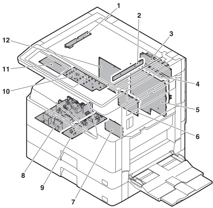
| No. | Name | Function and operation |
| 1 | Inverter PWB | Copy lamp control |
| 2 | CCD PWB | For image scanning (read) |
| 3 | Option connector PWB | |
| 4 | IMC PWB | Image process |
| 5 | MCU PWB | Main unit control |
| 6 | Mother board | Connection with FAX PWB |
| 7 | Tray interface PWB | 2nd tray control |
| 8 | DC power supply PWB | DC voltage control |
| 9 | High voltage PWB | High voltage control |
| 10 | KEY PWB | |
| 11 | OPU PWB | Operation panel control |
| 12 | SPLC PWB | Output image signal |
12. Rouleau
| No. | Name | Function and operation |
| 1 | Paper exit roller | Paper exit roller |
| 2 | Transport roller | Paper transport roller |
| 3 | Upper heat roller | Fuses toner on paper.(with the Teflon roller) |
| 4 | Lower heat roller | Fuses toner on paper.(with the silicone rubber roller) |
| 5 | DUP transport follower roller | Duplex paper transport |
| 6 | DUP transport roller | Duplex paper transport |
| 7 | Transport roller | Transfer images on the drum onto paper. |
| 8 | Resist roller | Synchronize the paper lead edge with the image lead edge. |
| 9 | Manual paper feed roller | Picks up papers in manual paper feed port. |
| 10 | Manual feed transport roller | Transports paper from the manual paper feed port. |
| 11 | 1st tray pick-up roller | Picks up paper from the tray. |
| 12 | 1st tray paper feed roller | Transports the picked up paper to RESIST section. |
| 13 | 2nd tray pick-up roller | Picks up paper from the tray. |
| 14 | 2nd tray paper feed roller | Transports the picked up paper to RESIST section. |
[5] RÉGLAGES
1. Liste des éléments de réglage
| Section | Adjustment item | Adjustment procedure/SIM No. | |||
| A | Process section | (1) | Developing doctor gap adjustment | Developing doctor gap adjustment | |
| (2) | MG roller main pole position adjustment | MG roller main pole position adjustment | |||
| (3) | Developing bias voltage adjustment | SIM8-1 | |||
| (4) | Grid bias voltage adjustment | SIM8-2 | |||
| B | Mechanism section | (1) | Print start position adjustment | SIM50-5 | |
| (2) | RSPF image lead edge position adjustment | SIM50-6 | |||
| (3) | Rear edge void adjustment | SIM50-1 | |||
| (4) | Paper off center adjustment | SIM50-10 | |||
| (5) | Left edge void area adjustment | SIM50-1-8 | |||
| (6) | Main scanning direction (FR direction) distortion balance adjustment | No. 2/3 mirror base unit installing position adjustment | |||
| Copy lamp unit installing position adjustment | |||||
| (7) | Sub scanning direction (scanning direction) distortion adjustment | Winding pulley position adjustment | |||
| (8) | Main scanning direction (FR direction) distortion balance adjustment | Rail height adjustment | |||
| (9) | Main scanning direction (FR direction) magnification ratio adjustment | SIM48-1-1 | |||
| (10) | Sub scanning direction (scanning direction) magnification ratio adjustment | a | OC mode in copying (SIM 48-1-2) | ||
| b | RSPF sub scanning direction magnification ratio (SIM48-1-3, 48-1-4) | ||||
| (11) | Off center adjustment (RSPF mode) | SIM50-12 | |||
| (12) | OC (RSPF) open/close detection position adjustment | SIM41-3 | |||
| (13) | Original sensor adjustment | SIM41-2, 41-4 (41-1) | |||
| (14) | RSPF white correction pixel position adjustment (required in an RSPF model when replacing the lens unit) | SIM63-7 | |||
| (15) | RSPF scan position auto adjustment | SIM53-8 | |||
| C | Image density (exposure) adjustment | (1) | Copy mode | SIM46-2 | |
2. Détails du réglage
A. Section de traitement
(1) Réglage de l'écart du docteur de développement
1) Retirez le capot du docteur.
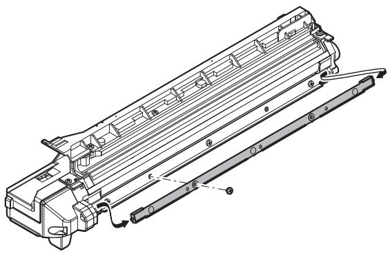
2) Desserrez la vis de fixation A du docteur de développement. 3) Insérez une jauge d'épaisseur de 1,5 mm aux positions des trois vis sur le docteur de développement, comme indiqué.
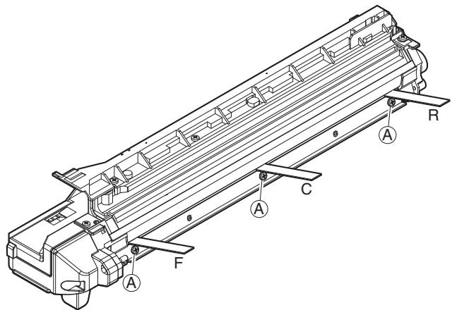
4) Serrez la vis de fixation du docteur de développement. 5) Vérifiez le jeu du docteur de développement. S'il est dans la plage spécifiée, fixez la vis de fixation avec du frein filet. * Lors de l'insertion de la jauge d'épaisseur, veillez à ne pas rayer le docteur de développement ni le rouleau MG.
Écart du docteur de développement
F/C/R : 1,5 + 0,1 mm
F/C/R : 1,5 - 0,15 mm
(2) Réglage de la position du pôle principal du rouleau MG
1) Placez l'unité de développement sur une surface plane. 2) Attachez une aiguille ou une épingle à une ficelle. 3) Tenez la ficelle et approchez l'aiguille du rouleau MG horizontalement. (N'utilisez pas de trombone, trop lourd pour un réglage correct.) (Placez l'unité de développement horizontalement pour ce réglage.) 4) Ne mettez pas l'aiguille en contact avec le rouleau MG, mais amenez-la à une position de 2 à 3 mm du rouleau MG. Marquez le point sur le rouleau MG qui se trouve sur la ligne prolongeant la pointe de l'aiguille. 5) Mesurez la distance entre la position marquée et le haut de la plaque du docteur de l'unité de développement pour vous assurer qu'elle est de 9,1 mm. Si la distance n'est pas dans la plage spécifiée, desserrez la vis de fixation A de la plaque de réglage du pôle principal et déplacez la plaque de réglage dans le sens de la flèche pour ajuster.
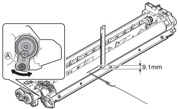
(3) Réglage de la tension de polarisation de développement (SIM 8-1)
1) Exécutez SIM 8-1.
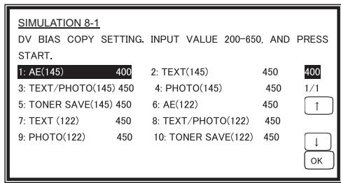
2) Touchez le mode d'exposition à modifier. La valeur de réglage actuelle est affichée. 3) Saisissez la valeur de réglage à l'aide du clavier numérique. 4) Appuyez sur la touche [START].
La sortie est effectuée avec la valeur saisie et l'affichage revient à l'état initial.
| Item | Content | Setting range | Default | |
| 1 | AE (145) | AE (145mm/s) | 200-650 | 450 |
| 2 | TEXT (145) | Character (145mm/s) | 450 | |
| 3 | TEXT/PHOTO (145) | Character/Photo (145mm/s) | 450 | |
| 4 | PHOTO (145) | Photo (145mm/s) | 450 | |
| 5 | TONER SAVE (145) | Toner save (145mm/s) | 400 | |
| 6 | AE (122) | AE (122mm/s) | 450 | |
| 7 | TEXT (122) | Character (122mm/s) | 450 | |
| 8 | TEXT/PHOTO (122) | Character/Photo (122mm/s) | 450 | |
| 9 | PHOTO (122) | Photo (122mm/s) | 450 | |
| 10 | TONER SAVE (122) | Toner save (122mm/s) | 400 | |
Unité minimale : incrément de -10 V
(4) Réglage de la tension de polarisation de grille (SIM 8-2)
1) Exécutez SIM 8-2.
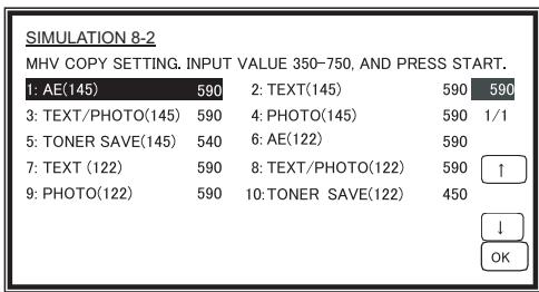
2) Touchez le mode d'exposition à modifier. La valeur de réglage actuelle est affichée.
3) Saisissez la valeur de réglage à l'aide du clavier numérique.
4) Appuyez sur la touche [START]. La sortie est effectuée avec la valeur saisie pendant 30 secondes, et l'affichage revient à l'état initial.
| Item | Content | Setting range | Default | |
| 1 | AE (145) | AE (145mm/s) | 350-750 | 590 |
| 2 | TEXT (145) | Character (145mm/s) | 590 | |
| 3 | TEXT/PHOTO (145) | Character/Photo (145mm/s) | 590 | |
| 4 | PHOTO (145) | Photo (145mm/s) | 590 | |
| 5 | TONER SAVE (145) | Toner save (145mm/s) | 540 | |
| 6 | AE (122) | AE (122mm/s) | 590 | |
| 7 | TEXT (122) | Character (122mm/s) | 590 | |
| 8 | TEXT/PHOTO (122) | Character/Photo (122mm/s) | 590 | |
| 9 | PHOTO (122) | Photo (122mm/s) | 590 | |
| 10 | TONER SAVE (122) | Toner save (122mm/s) | 540 | |
Unité minimale : incrément de -10 V
B. Section mécanisme
(1) Réglage de la position de début d'impression
1) Exécutez SIM 50-5.
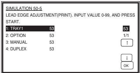
2) Touchez l'élément à régler. L'élément et la valeur actuellement définie sont mis en surbrillance. 3) Appuyez sur la touche [P]. L'affichage passe au menu de copie. 4) Sélectionnez le bac d'alimentation papier, la densité d'impression et le mode recto-verso. Saisissez la valeur de réglage à l'aide du clavier numérique. 5) Appuyez sur la touche [START]. La copie démarre.
| Item | Content | Setting range | Default | |
| 1 | TRAY1 | 1st tray | 0-99 | 53 |
| 2 | OPTION | Option tray | 1-99 | |
| 3 | MANUAL | Manual feed | ||
| 4 | DUPLEX | Back print | ||
6) Mesurez la distance H entre le bord avant du papier et la position de début d'impression de l'image. Réglez à nouveau la valeur de réglage de la position de début d'impression de l'image.
- 1 pas de la valeur de réglage correspond à environ un décalage de 0,127mm.
- Calculez la valeur de réglage à partir de la formule ci-dessous.
99 - H/0,127 (mm) = Valeur de réglage de la position de début d'impression de l'image
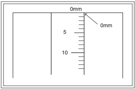
- Alignez le bord d'impression avec le bord du papier, et effectuez le réglage du bord avant.
Exemple : 99 - 5 / 0,127 = 99 - 39,4 = environ 59
Remarque : Si la valeur définie n'est pas obtenue à partir de la formule ci-dessus, effectuez un réglage fin.
7) Exécutez SIM 50-1-2 pour régler la marge de tête du bac principal.
- 1 pas de la valeur définie correspond à un décalage d'environ 0,127 mm.
- Calculez la valeur définie à partir de la formule ci-dessous.
B/0,127 (mm) = Valeur de réglage de la marge de tête
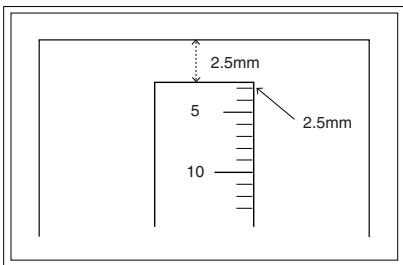
Exemple : Lors du réglage de la marge de tête à 2,5 mm :
2,5/0,127 = environ 20
| Adjustment mode | SIM | Set value | Spec value | Setting range |
| Main tray lead edge void | 50-1 | B/0.127 | Lead edge void: 1 – 4mm | 1 – 99 |
| -2 | ||||
| Print start position | 50-5 | 99 – H/0.127 | Image loss: 3mm or less |
[H : Valeur mesurée de la position de début d'impression (mm),
B : Marge de tête (mm)]
(2) Réglage de la position du bord avant de l'image RSPF
1) Placez une règle sur la glace d'exposition comme indiqué ci-dessous.
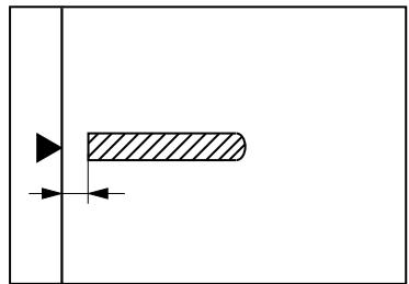
Remarque : Étant donné que la copie imprimée est utilisée comme mire, placez la règle parallèlement aux lignes de bord.
2) Effectuez une copie, puis utilisez la copie comme original pour effectuer à nouveau une copie RSPF. 3) Vérifiez la copie. Si nécessaire, effectuez les procédures de réglage suivantes. 4) Exécutez SIM 50-6. 5) Réglez la valeur de position du bord avant RSPF pour obtenir la même image que celle obtenue lors du réglage précédent de la position du bord avant de l'image OC.
| Adjustment mode | SIM | Set value | Spec value | Setting range |
| RSPF image lead edge position | 50-6 | 1 step: 0.127mm shift | Lead edge void: 1 – 4mm Image loss: 3mm or less | 1 – 99 |
(3) Réglage de la marge arrière
1) Placez une règle comme indiqué dans la figure ci-dessous.
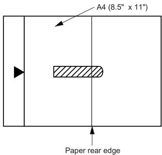
2) Réglez le format du document sur A4 (8,5" x 11") et faites une copie à 100 %. 3) Si un ajustement est nécessaire, suivez les procédures ci-dessous.
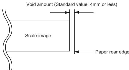
4) Exécutez SIM 50-1 et réglez le mode de densité sur DEN-B. La valeur d'ajustement actuellement définie s'affiche. 5) Saisissez la valeur définie et appuyez sur la touche de démarrage.
La valeur de correction est mémorisée et une copie est effectuée.
| Adjustment mode | SIM | Set value | Spec value | Setting range |
| Rear edge void | 50-1-6 | 1 step: 0.127mm shift | 4mm or less | 1 – 99 |
(4) Ajustement du décalage papier
1) Placez une mire de test (UKOG-0089CSZZ) sur la vitre d'exposition. 2) Sélectionnez une source d'alimentation papier et faites une copie. 3) Exécutez SIM 50-10.
| SIMULATION 50-10 PRINT OFF-CENTER ADJUSTMENT. INPUT VALUE 1-99, AND PRESS START. | ||
| 1: BYPASS | 50 | 50 |
| 2: TRAY1 | 50 | 1/1 |
| 3: TRAY2 | 50 | ↑ |
| 4: TRAY3 | 50 | |
| 5: TRAY4 | 50 | ↓ |
| 6: DUPLEX | 50 | OK |
4) Touchez l'élément à ajuster.
L'élément et la valeur actuellement définie sont mis en surbrillance.
5) Appuyez sur la touche [START].
L'écran bascule vers le menu de copie.
6) Sélectionnez le bac d'alimentation papier et la densité d'impression.
Saisissez la valeur d'ajustement à l'aide du clavier numérique.
7) Appuyez sur la touche [START].
La copie démarre.
| Item | Content | Setting range | Default | |
| 1 | BYPASS | Manual paper feed | 1-99 | 50 |
| 2 | TRAY1 | 1st tray | ||
| 3 | TRAY2 | 2nd tray | ||
| 4 | TRAY3 | 3rd tray | ||
| 5 | TRAY4 | 4th tray | ||
| 6 | DUPLEX | Back print | ||
| Adjustment mode | SIM | Set value | Spec value | Setting range |
| Paper off center | 50-10 -2 | Add 1: 0.127mm shift to R side. | Single: Center ±2.0mm | 1 – 99 |
| Reduce 1: 0.127mm shift to L side. | ||||
| Second print surface off-center | 50-10 -6 | Duplex: Center ±2.5mm |
(5) Ajustement de la zone de marge gauche
Remarque : avant d'effectuer cet ajustement, assurez-vous que l'ajustement du décalage papier (SIM 50-10) est terminé.
1) Exécuter SIM 50-1.
| SIMULATION 50-1 LEAD EDGE ADJUSTMENT. INPUT VALUE 1-99, AND PRESS START. | ||||
| 1: RRC-A | 43 | 2: DEN-A | 18 | 43 |
| 3: DEN-A -MANUAL | 18 | 4: DEN-A -OPTION | 18 | |
| 5: DEN-A -DUPLEX | 18 | 6: DEN-B | 3 | 1/1 |
| 7: DEN-B-DUP | 50 | 8: SIDE VOID | 18 | 1 |
| 9: SIDE VOID-DUP | 18 | 10: LOSS(OC) | 3 | |
| ↓ | ||||
| OK | ||||
2) Noter la valeur de réglage de SIM 50-5 (articles 1, 2, 3, 4), puis changer la valeur à 99. 3) Régler SIM 50-1 (articles 2, 3, 4, 5) à 1. (En réglant à 1, il n'y a pas de marge.) 4) Placer un graphique avec un bord d'attaque net (ou une règle) sur la table de documents OC. 5) Utiliser SIM 50-1 (article 1) pour exécuter un test d'impression. Vérifier l'impression et ajuster pour que l'image du bord d'attaque soit imprimée. (1 - 99 : environ 0,127 mm/pas) 6) Rétablir les valeurs de réglage de SIM 50-5 (articles 1, 2, 3, 4) aux valeurs d'origine, puis exécuter un test d'impression. Vérifier l'impression et ajuster pour que l'image du bord d'attaque soit imprimée sur le bord d'attaque du papier. (1 - 99 : environ 0,127 mm/pas). 7) Ajuster SIM 50-1 (articles 2, 3, 4, 5) pour que la marge du bord d'attaque sur l'impression soit la valeur spécifiée. (1 - 99 : environ 0,127 mm/pas) 8) Comme à la procédure 7, ajuster SIM 50-1 (articles 6, 7) pour que la marge du bord arrière soit la valeur spécifiée. (1 - 99 : environ 0,127 mm/pas) 9) Comme à la procédure 7, ajuster SIM 50-1 (articles 8, 9) pour que la marge du bord gauche soit la valeur spécifiée. (1 - 99 : environ 0,127 mm/pas) 10) Effectuer une copie agrandie (400 %) et vérifier qu'il n'y a pas d'ombre du boîtier imprimée sur le bord d'attaque. 11) S'il y a une ombre imprimée sur le bord d'attaque à la procédure 9, ajuster SIM 50-1 (article 10). (1 - 5 : environ 0,677 mm)
- S'il n'y a pas de problème, régler à 3.
| Item | Content | Setting range | Default | |
| 1 | RRC-A | Original scan start position adjustment Lead edge position adjustment value (OC) | 1-99 | 43 |
| 2 | DEN-A | Lead edge cancel adjustment (Main tray) | 1-99 | 18 |
| 3 | DEN-A-MANUAL | Lead edge cancel adjustment (Manual feed tray) | 1-99 | 18 |
| 4 | DEN-A-OPTION | Lead edge cancel adjustment (Option tray) | 1-99 | 18 |
| 5 | DEN-A-DUPLEX | Lead edge cancel adjustment (back of the machine) | 1-99 | 18 |
| 6 | DEN-B | Rear edge void adjustment | 1-99 | 30 |
| 7 | DEN-B-DUP | Rear edge void adjustment (Duplex) | 1-99 | 50 |
| 8 | SIDE VOID | Left edge void adjustment (First print surface) | 1-99 | 18 |
| 9 | SIDE VOID-DUP | Left edge void adjustment (Duplex) | 1-99 | 18 |
| 10 | LOSS(OC) | Image loss amount adjustment (Lead edge image loss set value) (OC) | 1-5 | 3 |
| Adjustment mode | SIM | Set value | Spec value | Setting range |
| Left edge void | 50-1 | 1 step: 0.127mm shift | 0.5 – 4mm | 1 – 99 |
| -8 |
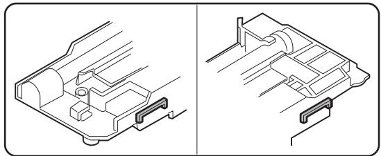
(6) Réglage de l'équilibre de distorsion dans le sens de balayage principal (direction FR)
1) Retirer la vitre OC, le panneau droit et le capot supérieur droit.
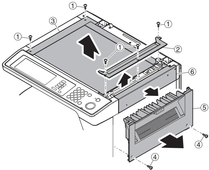
2) Desserrer la vis de fixation du câble de l'unité de lampe de copie.
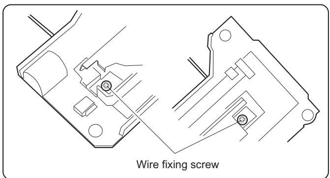
3) Tourner manuellement la poulie d'entraînement de la base de miroir et amener l'unité de base de miroir n° 2/3 en contact avec la plaque de positionnement.
À ce moment, si les côtés du cadre avant et du cadre arrière de l'unité de base de miroir n° 2/3 sont en contact avec la plaque de positionnement en même temps, le parallélisme de l'unité de base de miroir est correct. Si l'un d'eux est en contact avec la plaque de positionnement, effectuer le réglage de 4).
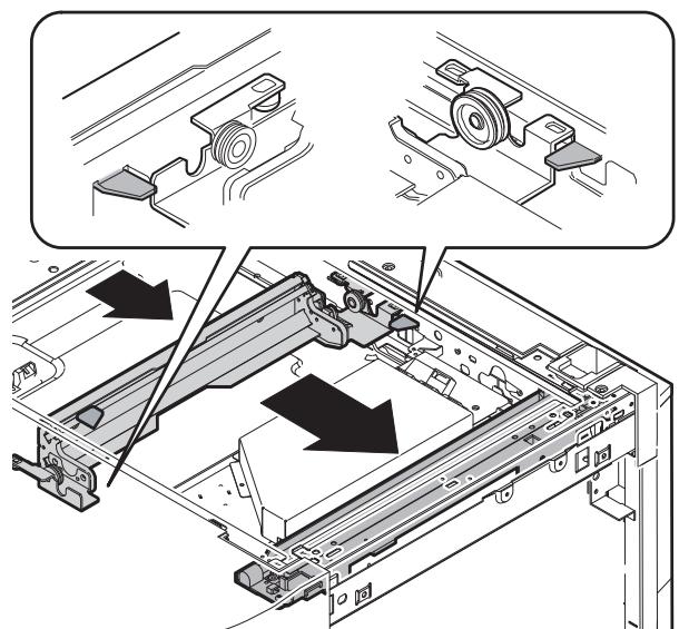
4) Desserrer la vis de fixation de la poulie d'entraînement du scanner qui n'est pas en contact avec la plaque de positionnement de l'unité de base de miroir n° 2/3.
5) Sans déplacer l'arbre de la poulie d'entraînement du scanner, tourner manuellement la poulie d'entraînement du scanner jusqu'à ce que la plaque de positionnement soit en contact avec l'unité de base de miroir n° 2/3, puis fixer la poulie d'entraînement du scanner.
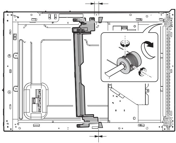
6) Remettre l'unité de base de miroir n° 2/3 sur la plaque de positionnement, pousser les projections sur les côtés du cadre avant et du cadre arrière de l'unité de lampe de copie vers le cadre d'angle, et serrer la vis de fixation du câble.
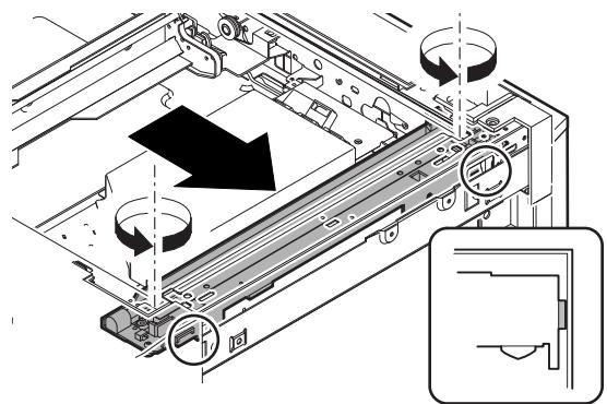
(7) Réglage de la distorsion dans le sens de balayage secondaire (sens de numérisation) (réglage de la position de la poulie d'enroulement)
Ce réglage doit être effectué dans les cas suivants :
- Lorsque le câble d'entraînement de la base de miroir est remplacé.
- Lorsque l'unité de lampe ou le support de miroir n° 2/3 est remplacé.
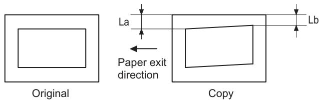
- Lorsqu'une copie comme celle montrée est réalisée.
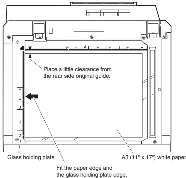
1) Placez du papier blanc A3 (11" x 17") sur la table d'origine comme indiqué ci-dessous.
2) Ouvrez le couvercle d'origine et effectuez une copie normale (100%). 3) Mesurez la largeur du fond noir au bord avant et au bord arrière.
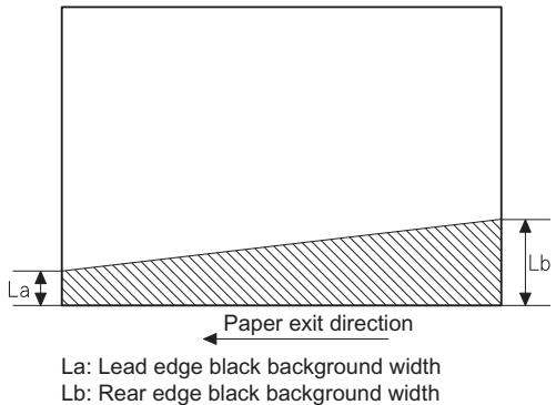
Si la largeur (La) du fond noir au bord avant est égale à celle (Lb) au bord arrière, il n'est pas nécessaire d'exécuter les procédures suivantes de 4) à 7).
4) Desserrez la vis de fixation de la poulie d'entraînement de la base du miroir sur le côté du cadre avant ou sur le côté du cadre arrière.
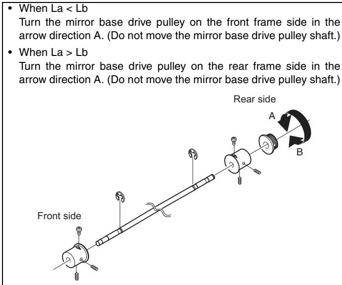
5) Serrez la vis de fixation de la poulie d'entraînement de la base du miroir.
La = Lb
6) Exécutez à nouveau le réglage de l'équilibre de distorsion dans le sens de balayage principal (FR) décrit précédemment en 2).
(8) Réglage de l'équilibre de distorsion dans le sens de balayage principal (direction FR) (réglage de la hauteur du rail)
Lorsqu'il n'y a pas de copie oblique dans le sens de balayage de la base du miroir et qu'il n'y a pas d'erreur horizontale (perpendiculaire au sens de balayage), le réglage peut être effectué en ajustant la hauteur du rail de l'unité de base des miroirs n° 2/3.
Avant d'effectuer ce réglage, assurez-vous d'effectuer le réglage de distorsion d'image horizontale dans la section du scanner laser.
Ce réglage doit être effectué dans les cas suivants :
- Lorsque le câble de la base du miroir est remplacé.
- Lorsque l'unité de lampe de copie et l'unité de miroirs n° 2/3 sont remplacées.
- Lorsque le rail de l'unité de miroirs est remplacé et déplacé.
- Lors d'une copie ultérieure.
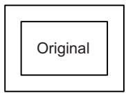
1) Créez un original pour le réglage.
Préparez une feuille de test en traçant des lignes parallèles à 10 mm des deux extrémités d'une feuille de papier blanc A3 (11'' × 17'') comme indiqué ci-dessous. (Ces lignes doivent être correctement parallèles entre elles.)
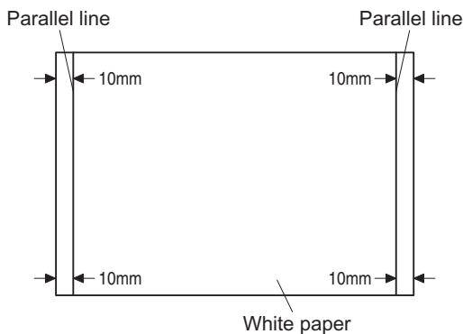
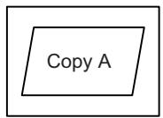
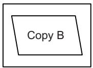
2) Effectuez une copie normale (100 %) de la feuille de test sur du papier A3 (11'' × 17''). (Alignez le bord du papier avec le bord de la plaque de verre.) 3) Mesurez les distances (La, Lb, Lc, Ld) aux quatre coins comme indiqué ci-dessous.
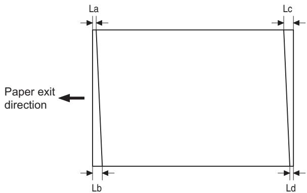
Si La = Lb et Lc = Ld, il n'est pas nécessaire d'effectuer les procédures 4) et 5).
4) Déplacez la position du rail de la base du miroir B vers le haut ou vers le bas (dans le sens de la flèche) pour effectuer le réglage.
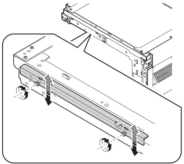
- Si La > Lb
- Déplacez le rail de la base du miroir B vers le haut de la moitié de la différence (La - Lb).
- Si La < Lb Déplacez le rail de la base du miroir B vers le bas de la moitié de la différence (Lb - La). Exemple : Si La = 12 mm et Lb = 9 mm, déplacez le rail de la base du miroir B vers le haut de 1,5 mm.
- Si Lc > Ld Déplacez le rail de la base du miroir B vers le bas de la moitié de la différence (Lc - Ld).
- Si Lc < Ld
- Si Lc < Ld, déplacez la base du miroir B du côté de l'alimentation papier vers le haut.
- Lors du déplacement du rail de la base du miroir, tenez le rail de la base du miroir avec votre main.
La = Lb, Lc = Ld
5) Après la fin du réglage, tournez manuellement la poulie d'entraînement de la base du miroir, faites parcourir complètement la base du miroir A et la base du miroir B, et vérifiez que les bases du miroir n'entrent pas en contact l'une avec l'autre. * Si le rail de la base du miroir est déplacé de manière excessive, la base du miroir peut entrer en contact avec le châssis ou la vitre d'exposition. Soyez prudent pour éviter cela.
(9) Réglage du taux de grandissement dans le sens de balayage principal (direction FR) (SIM 48-1)
Remarque : avant d'effectuer ce réglage, assurez-vous que le bloc CCD est correctement installé.
1) Placez une règle sur la glace d'exposition comme indiqué ci-dessous.
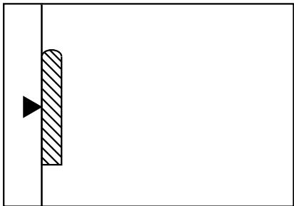
2) Exécutez SIM 48-1. 3) Après le préchauffage, l'ombrage est effectué et la valeur actuelle du taux de grandissement dans le sens de balayage principal s'affiche sur l'écran sur 2 chiffres. 4) Mode de correction manuelle (SIM48-1-1)
Saisissez la valeur définie et appuyez sur la touche de démarrage.
La valeur de correction est mémorisée et une copie est effectuée.
Remarque : le jugement doit être fait avec une largeur de 200 mm, et non avec une largeur de 100 mm.
| Adjustment mode | Spec value | SIM | Set value | Setting range |
| Main scanning direction magnification ratio | At normal: ±1.0% | 48-1-1 | Add 1: 0.1% increase Reduce 1: 0.1% decrease | 1 – 99 |
(10) Réglage du taux de grandissement dans le sens de balayage secondaire (sens de balayage) (SIM 48-1-2, SIM 48-1-3)
a. Mode OC en copie
Remarque : exécutez la procédure après avoir terminé SIM 48-1-1.
1) Placez une règle sur la glace d'exposition comme indiqué ci-dessous, puis effectuez une copie normale à 100 %.
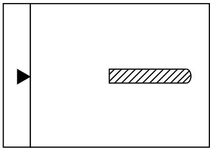
2) Comparez l'image de la règle avec la règle réelle. Si nécessaire, effectuez les procédures de réglage suivantes. 3) Exécutez SIM 48-1-2. 4) Saisissez la valeur définie et appuyez sur la touche de démarrage. La valeur définie est mémorisée et une copie est effectuée.
| Adjustment mode | Spec value | SIM | Set value | Setting range |
| Sub scanning direction magnification ratio (OC mode) | At normal: ±1.0% | 48-1-2 | Add 1: 0.05% increase Reduce 1: 0.05% decrease | 1 – 99 |
b. Mode RSPF en copie
Remarque : avant d'effectuer ce réglage, assurez-vous que le bloc CCD est correctement installé et que le réglage du mode OC en copie est terminé.
1) Placez une règle sur la glace d'exposition comme indiqué ci-dessous, puis effectuez une copie normale à 100 % pour créer un test.
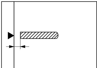
Remarque : comme la copie imprimée est utilisée comme mire de test, placez la règle parallèlement au bord avant de la vitre.
2) Placez la mire de test sur le RSPF et effectuez une copie normale à 100 %. 3) Comparez l'image de la règle avec l'image réelle. Si nécessaire, effectuez les procédures de réglage suivantes. 4) Exécutez SIM 48-1-3. 5) Après le préchauffage, l'ombrage est effectué. La valeur de correction actuelle du rapport de grandissement dans le sens de sous-balayage de la surface avant est affichée sur deux chiffres sur l'écran.
6) Saisissez la valeur définie et appuyez sur la touche de démarrage. La valeur définie est mémorisée et une copie est effectuée. 7) Exécutez SIM 48-1-4. Le rapport de grandissement actuel dans le sens de sous-balayage de la surface arrière est affiché sur deux chiffres sur l'écran. 8) Saisissez la valeur définie et appuyez sur la touche de démarrage. La valeur définie est mémorisée et une copie est effectuée.
| Adjustment mode | Spec value | SIM | Set value | Setting range |
| Sub scanning direction magnification ratio (RSPF mode) | At normal: ±1.0% | 48-1-3 48-1-4 | Add 1: 0.05% increase Reduce 1: 0.05% decrease | 1 – 99 |
(11) Réglage du décentrement (mode RSPF)
Remarque : avant d'effectuer ce réglage, assurez-vous que le décentrement du papier est correctement réglé.
1) Placez la mire de test de position centrale (feuille avec une ligne droite dans le sens de balayage au centre) sur le RSPF. 2) Effectuez une copie normale à partir du bac d'alimentation manuelle et vérifiez la copie imprimée avec la mire de test. Si un réglage est nécessaire, effectuez la procédure suivante. 3) Exécutez SIM 50-12. 4) Après le préchauffage, l'ombrage est effectué et la valeur de réglage actuelle du décentrement est affichée sur deux chiffres sur l'écran. 5) Saisissez la valeur définie et appuyez sur la touche de démarrage. La valeur définie est mémorisée et une copie est effectuée.
| Adjustment mode | Spec value | SIM | Set value | Setting range |
| Original off center mode (RSPF mode) | Single: Center ± 3.0mm | 50-12 | Add 1: 0.1mm shift to R side | 1 – 99 |
| Duplex: Center ±3.5mm | Reduce 1: 0.1mm shift to L side |
(12) Réglage de la position de détection d'ouverture/fermeture de l'OC (RSPF)
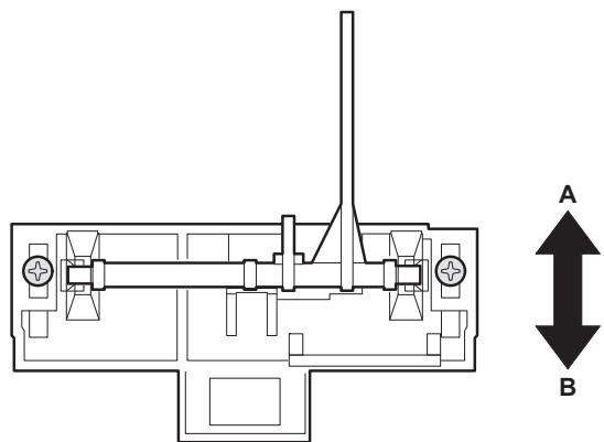
1) Exécutez SIM 41-3. 2) Fermez progressivement l'OC (RSPF) depuis la position complètement ouverte et mesurez la distance A lorsque l'affichage sur le panneau de commande change. (Voir la figure ci-dessous.)
Distance A = dessus de la vitre - nervure de la poignée de l'OC (RSPF)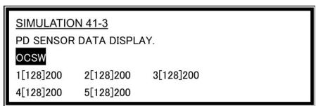
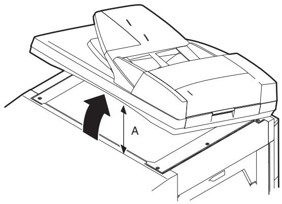
Position d'ouverture/fermeture de l'OC (SPF) A : 125 - 225 mm
3) Si la distance est hors de la plage spécifiée, ajustez la position de la plaque de fixation du capteur d'ouverture/fermeture comme indiqué ci-dessous.
- Distance < 125 mm : déplacer vers A.
- Distance > 225 mm : déplacer vers B.
(13) Réglage du capteur d'original (SIM 41-2, 41-4)
1) Placez du papier A3 (11'' × 17'') sur la table OC. (Gardez le SPF (couvercle OC) ouvert.) 2) Exécutez SIM 41-2. 3) Maintenez A = 125 mm et exécutez SIM 41-4. (Ne placez pas de papier sur la table.) 4) Vérifiez la réaction avec SIM 41-1.
(14) Réglage de la position de correction du point blanc RSPF (requis dans un modèle RSPF lors du remplacement de l'unité de lentille) (SIM63-7)
1) Ouvrez complètement le RSPF. 2) Exécutez SIM 63-7. 3) Lorsque le panneau de commande affiche "COMPLETE", le réglage est terminé. 4) Si le panneau de commande affiche "ERROR", effectuez les mesures suivantes.
- Lorsque l'affichage est 0 : Vérifiez que le SPF est ouvert.
Vérifiez que la lampe est allumée. (Si la lampe est éteinte, vérifiez le connecteur MCU.)
Vérifiez que le câble CCD est correctement inséré dans le connecteur MCU.
- Lorsque l'affichage est 281 ou plus :
1) Retirez la vitre de la table. 2) Retirez la boîte noire. 3) Faites glisser l'unité de lentille vers l'avant et fixez-la, puis exécutez SIM.
- Lorsque l'affichage est 143 ou moins :
1) Retirez la vitre de la table. 2) Retirez la boîte noire. 3) Faites glisser l'unité de lentille vers l'arrière et fixez-la, puis exécutez SIM.
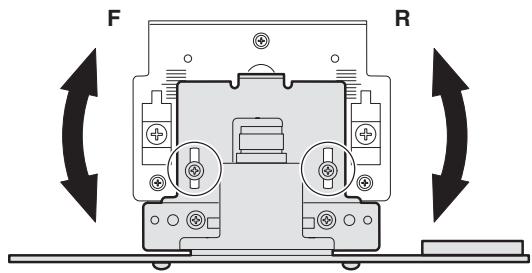
- Lorsque l'unité de lentille est déplacée, exécutez le réglage automatique du rapport de grandissement de balayage principal OC, SIM 48-1-1.
- Ce réglage est fondamentalement correct avec SIM 63-7.
(15) Réglage automatique de la position de numérisation RSPF
[Fonction]
Utilisé pour régler automatiquement la position de numérisation RSPF.
[Opération]
1) Avec le capot RSPF ou OC ouvert, placez un fond de papier blanc sur la vitre OC. (Dans le modèle standard RSPF, la surface de la vitre RSPF est incluse.) 2) Entrez SIM53-08, puis appuyez sur la touche [START]. Description de la simulation : l'unité optique est déplacée pour reconnaître la limite entre la vitre OC et le capot en verre RSPF. Avec la même position que la référence, la position de numérisation RSPF est automatiquement ajustée.
- Après la fin de l'ajustement automatique de la position de numérisation RSPF, l'ajustement du bord avant RSPF doit être exécuté. (Les deux faces)
- Aucune autre feuille que le graphique noir ne doit se trouver sur la surface de la vitre.
- Surtout lors de la numérisation RSPF, la zone centrale est scannée dans la direction de balayage principale. Faites attention à empêcher la lumière externe de pénétrer dans la zone de numérisation. 3) Vérifiez que le bord avant n'est pas décalé. (Les deux faces) (Si l'ajustement du bord avant de l'original a été fait correctement, même si la position de numérisation est décalée, elle est suivie automatiquement.)
![SHARP AR 5726 - [Opération] - 1](/content/2024/11/201360/images/f65ed6b85b34261cdc2ad1f822b5a0ecdbb732501d466b79d15aa13d01dddeab.jpg)
C. Ajustement de la densité (exposition) de l'image
(1) Mode copie (SIM46-2)
1) Placez une mire de test (UKOG-0162FCZZ) sur la table OC comme indiqué ci-dessous.
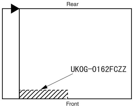
2) Placez trois feuilles ou plus de papier A3 (11" x 17") sur la mire de test. 3) Exécutez SIM 46-2. 4) Après le préchauffage, l'ombrage est effectué et la valeur de réglage actuelle du niveau de densité (exposition) est affichée sur l'écran en 2 chiffres.
Pour la sélection du mode, utilisez les [touches numériques].
5) Modifiez la valeur de réglage avec les [touches numériques] pour ajuster la densité de l'image copiée. 6) Effectuez une copie et vérifiez que la spécification ci-dessous est satisfaite.
Remarque : placez les originaux dans la référence arrière et la mire de test dans la référence avant lors de l'ajustement de l'exposition.
| Density mode | Exposure level | Sharp Gray Chart output | Set value | Setting range |
| AUTO | - | "3" is copied. | If too bright, increase the quantity displayed on the copy quantity display. | 1 - 99 |
| TEXT | 3.0 | "3" is copied. | ||
| TEXT/PHOTO | 3.0 | "3" is copied. | ||
| PHOTO | 3.0 | "2" is copied. | ||
| AE (TONER SAVE) | - | "3" is copied. | If too dark, decrease the quantity displayed on the copy quantity display. | |
| TEXT (TONER SAVE) | 3.0 | "3" is copied. | ||
| TEXT PHOTO (TONER SAVE) | 3.0 | "3" is copied. |
[6] SIMULATION
1. Généralités
A. Aperçu et objectif
La simulation a les fonctions suivantes pour comprendre l'état de fonctionnement de la machine, identifier la position du problème et les causes à un stade précoce, et effectuer divers réglages et ajustements rapidement pour améliorer la maintenabilité de la machine.
1) Divers réglages 2) Configuration des spécifications et fonctions 3) Résolution des problèmes 4) Vérification du fonctionnement 5) Vérification, configuration et remise à zéro des divers compteurs 6) Vérification et effacement des données d'état de fonctionnement de la machine (historique des opérations) 7) Transfert de diverses données (réglages, configuration, opérations, compteurs)
Les procédures d'exploitation et les affichages diffèrent selon la forme du panneau de commande de la machine.
B. Simulation de type code
(1) Procédures et opérations
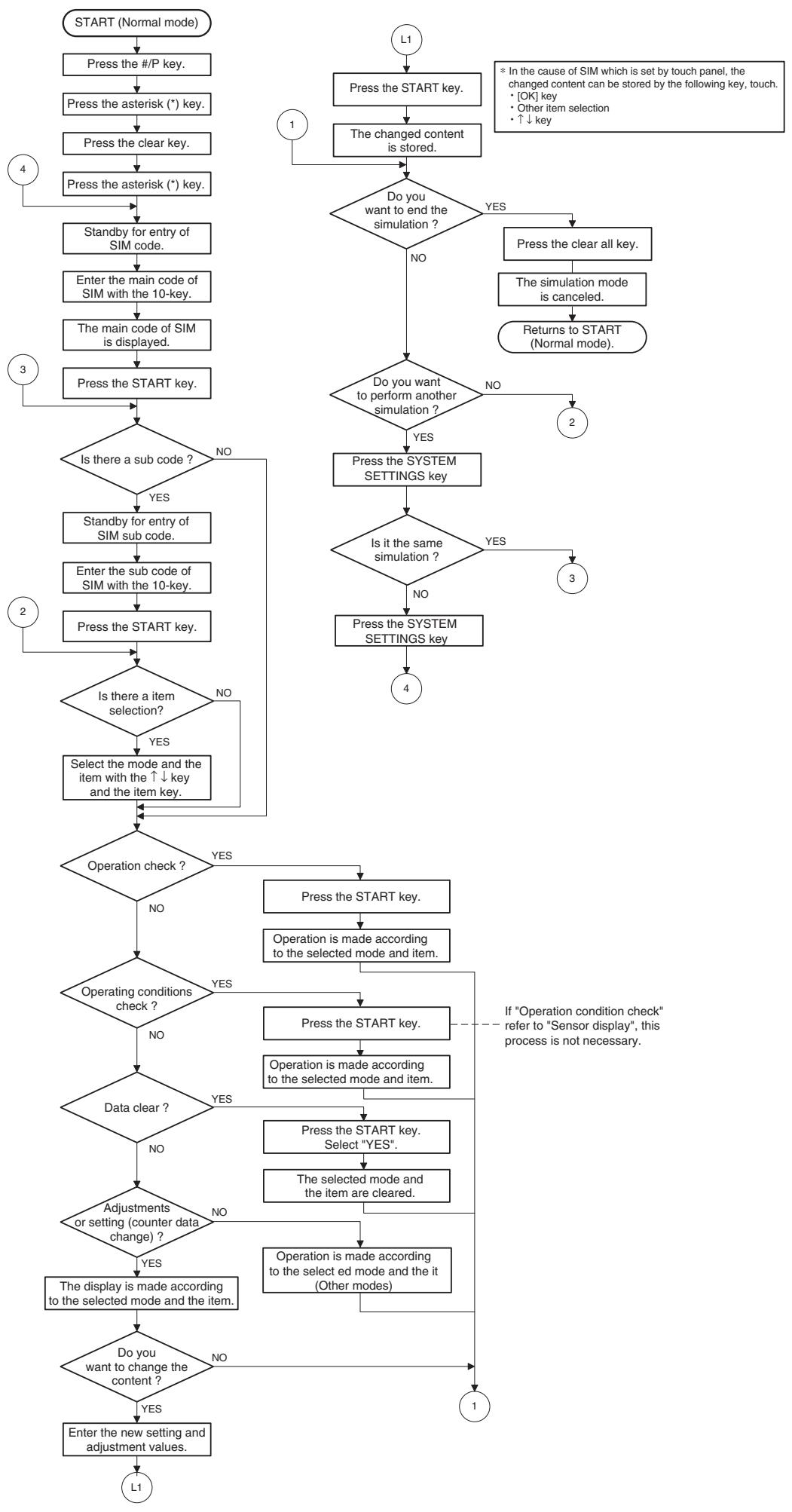
- Entrée en mode simulation : 1) Touche #/P (programme) ON → touche Astérisque (*) ON → touche CLEAR ON → touche Astérisque (*) ON → prêt pour la saisie du code principal de simulation. 2) Saisie du code principal avec le pavé numérique → touche START ON. 3) Saisie du sous-code avec le pavé numérique → touche START ON. 4) Sélectionnez un élément avec la touche de défilement et la touche d'élément. 5) La machine entre dans le mode correspondant à l'élément sélectionné. Appuyez sur la touche START pour démarrer l'opération de simulation.
Pour annuler le mode simulation actuel ou pour changer le code principal et le sous-code, appuyez sur la touche SYSTEM SETTINGS.
- Annulation du mode simulation pour revenir au mode normal
1) Appuyez sur la touche CLEAR ALL.
(2) Comment modifier la valeur de réglage de simulation définie par le panneau tactile lors du processus de saisie de la valeur de réglage
a. Liste SIM cible
3-7, 8-1, 8-2, 8-3, 8-10, 8-11, 8-12, 9-5, 43-1, 44-34, 46-2, 46-9, 46-10, 46-11, 46-18, 46-20, 46-30, 46-31, 48-1, 48-2, 50-1, 50-5, 50-6, 50-10, 50-12, 51-1, 51-2, 51-9, 53-7
b. Procédure d'utilisation du panneau tactile
- Dans le menu de configuration des valeurs de réglage, l'élément sélectionné est mis en surbrillance. La modification est effectuée sur la valeur de réglage de simulation mise en surbrillance.
- Si toute la liste des éléments de réglage n'est pas affichée sur une seule page, touchez les boutons [↑] et [↓] pour changer de page.
- Pour modifier une valeur de réglage, touchez l'élément à modifier. (L'élément sélectionné est mis en surbrillance.) Saisissez la valeur de réglage et effectuez l'une des procédures suivantes : l'affichage de la valeur de réglage de l'élément sélectionné est mis à jour ainsi que la valeur de réglage.
1) Appuyez sur la touche [OK]. 2) Touchez un autre élément sélectionné pour modifier l'état de la sélection. 3) Si la liste des éléments de réglage couvre deux pages ou plus, touchez les touches [] et [] pour changer de page. 4) Appuyez sur la touche [START]. * Pour les simulations qui permettent l'impression de confirmation, la copie démarre après modification de la valeur de réglage.
(46-2, 46-9, 46-10, 46-11, 46-18, 48-1, 48-2, 50-1, 50-5, 50-6, 50-10, 50-12, 51-2, les éléments en gras dans la liste ci-dessus.)
- Si la valeur saisie est en dehors de la plage de réglage, un buzzer d'erreur retentit et la valeur de réglage n'est pas renouvelée. Le changement de page n'est pas non plus effectué.
- Liste des codes de simulation
| Code | Function | |
| Main | Sub | |
| 1 | 1 | Used to check the operation of the scanner unit and its control circuit. |
| 2 | Used to check the operation of sensor and detector in the scanning (read) section and the related circuit. | |
| 2 | 1 | Used to check the operation of the RSPF unit and the related circuit. |
| 2 | Used to check the operation of sensors and detectors in the RSPF unit and the related circuit. | |
| 3 | Used to check the operation of the loads in the RSPF unit and the control circuits. | |
| 3 | 2 | Used to check the operation of sensor and detector in the finisher and the related circuit. |
| 3 | Used to check the operation of the load in the finisher and the control circuit. | |
| 10 | Used to make each adjustment of the finisher. | |
| 11 | Used to check the shifter operation. Reciprocating operations are continuously performed or the home position is checked. (The shifter is shifted to the home position or moved in one way by the specified steps.) | |
| 4 | 2 | Used to check the operation of sensor and detector in the option tray and the related circuit. |
| 3 | Used to check the operation of the load in the option tray and the control circuit. | |
| 5 | 1 | Used to check the operation of the display (LED), LCD in the operation panel, and control circuit. |
| 2 | Used to check the operation of the heater lamp and the control circuit. | |
| 3 | Used to check the operation of the copy lamp and the control circuit. | |
| 6 | 1 | Used to check the operation of the loads (clutches and solenoids) in the paper transport system and the control circuit. |
| 2 | Used to check the operation of each fan motor and its control circuit. | |
| 7 | 1 | Used to set the aging operation conditions. |
| 6 | Used to set the cycle of intermittent aging. | |
| 8 | Used to set the display of the warm-up time. | |
| 8 | 1 | Used to check and adjust the operation of the developing bias voltage in each copy mode and the control circuit. |
| 2 | Used to check and adjust the operation of the main charger grid voltage in each copy mode and the control circuit. | |
| 10 | Used to check and adjust the operation of the developing bias voltage in each printer mode and the control circuit. | |
| 11 | Used to check and adjust the operation of the main charger grid voltage in each printer mode and the control circuit. | |
| 13 | Used to check and adjust the operation of the developing bias voltage in FAX mode and the control circuit. | |
| 14 | Used to check and adjust the operation of the main charger grid voltage in FAX mode and the control circuit. | |
| 9 | 1 | Used to check and adjust the operation of the load (motor) in the duplex section and the control circuit. |
| 4 | Duplex motor RPM setting | |
| 5 | Used to adjust the timing of switching from normal rotation to reverse rotation or from reverse rotation to normal rotation of the duplex motor. | |
| 10 | 0 | Used to check the operation of the toner motor and its control circuit. |
| Code | Function | |
| Main | Sub | |
| 14 | 0 | Used to cancel excluding the self-diag U2/PF troubles. |
| 16 | 0 | Used to cancel the self-diag U2 trouble. |
| 17 | 0 | Used to cancel the self diag “PF” trouble. |
| 21 | 1 | Used to set the maintenance cycle. |
| 22 | 1 | Used to check the counter value of each section. |
| 2 | Used to check the total numbers of misfeed and troubles. (When the number of misfeed is considerably great, it is judged as necessary for repair. The misfeed rate is obtained by dividing this count value with the total counter value.) | |
| 3 | Used to check the misfeed positions and the number of misfeed at each position. (When the number of misfeed is considerably great, it can be judged as necessary for repair.) | |
| 4 | Used to check the total trouble (self diag) history. | |
| 5 | Used to check the ROM version of each unit (section). | |
| 6 | Used to print each system setting, the account information, and the machine adjustment values. | |
| 7 | Used to display of the administrator password. | |
| 8 | Used to display the original, staple counter. | |
| 9 | Used to check the number of use of each paper feed section. (the number of prints) | |
| 10 | Used to check the system configuration. | |
| 11 | Used to display the FAX send/receive counter (FAX reception and print counter). | |
| 12 | Used to check the misfeed positions and the number of misfeed at each position. (When the number of misfeed is considerably great, it can be judged as necessary for repair.) | |
| 13 | Used to display the CRUM type. | |
| 19 | Used to display the scanner counter in the network scanner mode. | |
| 24 | 1 | Used to clear the misfeed counter, the misfeed history, the trouble counter, and the trouble history. (The counters are cleared after completion of maintenance.) |
| 2 | Used to clear the number of use (the number of prints) of each paper feed section. | |
| 3 | Used to clear the number usage data of the stapler, RSPF, and scanning. | |
| 4 | Used to reset the maintenance counter. | |
| 5 | Used to reset the developer counter. (The developer counter of the DV unit which is installed is reset.) | |
| 6 | Used to clear the copy counter. | |
| 7 | Used to clear the OPC drum (membrane decrease) correction counter. (This simulation is executed when the OPC drum is replaced.) | |
| 9 | Used to clear the printer counter and other counters. | |
| 10 | FAX counter data clear | |
| 15 | Used to clear the scanner counter in the network scanner mode. | |
| 25 | 1 | Used to check the operation of the main drive (excluding the scanner section) and to check the operation of the toner concentration sensor. (The toner concentration sensor output can be monitored.) |
| 2 | Used to make the initial setting of toner concentration when replacing developer. | |
| 26 | 1 | Used to set whether the job separator is installed or not. (Since this cannot be detected by hardware detection, it is set in this simulation.) |
| 26 | 2 | Used to set whether the automatic detection of paper size is made or not. |
| 3 | Used to set the specifications of the auditor. Setting must be made depending on the use condition of the auditor. | |
| 5 | Used to set the count mode of the total counter and the maintenance counter. | |
| 6 | Used to set the specifications depending on the destination. | |
| 12 | Used to input the Software Key for E-MAIL RIC. | |
| 14 | Used to input the Software Key for the PS extension kit. | |
| 18 | Used to set enable/disable of toner save operation. | |
| 22 | Used to set the specification (language display) for the destination. | |
| 30 | Used to set ON/OFF of the heater lamp slow-up control conforming to the CE mark control. | |
| 35 | Used to set whether the same continuous troubles are displayed as one trouble or the series of troubles with SIM 22-4 when the same troubles occur continuously. | |
| 36 | Used to set whether the machine is stopped or not when the maintenance counter life is expired. | |
| 37 | Used to set whether the machine is stopped or not when the developer counter life is expired. | |
| 38 | Used to set whether the machine is stopped or not when the drum counter life is expired. | |
| 50 | Used to set ON/OFF of the black and white reversion function. | |
| 56 | Gamma life correction setting | |
| 57 | Used to set the model code. | |
| 60 | Used to set enable/disable of the FAX mode key when FAX is not installed. (When FAX is installed, the FAX mode is enabled regardless of this setup.) | |
| 71 | In the power save time setting, the pre-heat (pre-heat mode setting) and the auto power shut off time can be set to the short time setup (pre-heat: 1 min, auto power shut off: 1 min) and the long time setup (pre-heat: 15min, auto power shut off: 60min). | |
| 72 | The letterhead support is set. When "Letterhead paper setting" is selected, the set value of SIM 26-46 (Image output direction setting) is set to "Setting Enable" accordingly. | |
| 30 | 1 | Used to display the sensor status attached to the machine. |
| 2 | Used to display the status of the sensors attached to the standard tray and the manual feed tray. (Use SIM 4-2 for the option trays.) The sensor of an uninstalled tray is not displayed. | |
| 40 | 1 | Used to check the sensor of the machine manual feed tray. |
| 2 | Used to adjust the manual paper feed tray paper width detector detection level. | |
| 3 | The AD conversion value of manual feed width detection is displayed. | |
| 41 | 1 | Used to check the document size detection photo sensor. |
| 2 | Used to adjust the detection level of the document size photo sensor. | |
| 3 | Used to check the light reception level and the detection level of the original size detection photo sensor. | |
| 4 | Used to adjust the detection level of OC 20 degrees. | |
| Code | Function | |
| Main | Sub | |
| 43 | 1 | Used to set the fusing temperature. |
| 10 | Used to set the paper feed cycle timing when printing postcards. | |
| 44 | 1 | Used to make various setups in each mode of process control. |
| 2 | Drum life correction setting | |
| 3 | Used to set the DV count correction. | |
| 9 | Used to display the process control correction information. | |
| 14 | Used to display the environment (temperature, humidity) correction information. | |
| 16 | Used to set the toner density control correction value. | |
| 17 | Used to display the toner density control reference value. | |
| 34 | Used to set the transfer current value in each mode. | |
| 40 | Used to set the time from the start of the main motor rotation (Ready) to the start of toner supply in previous rotation after turning on the power. | |
| 46 | 2 | Used to set the exposure level in each exposure mode. |
| 9 | Used to adjust the shift amount and the inclination value for each level (1 to 5) of the exposure mode (Text). | |
| 10 | Used to adjust the shift amount and the inclination value for each level (1 to 5) of the exposure mode (Text/Photo). | |
| 11 | Used to adjust the shift amount and the inclination value for each level (1 to 5) of the exposure mode (Photo). | |
| 12 | FAX exposure level adjustment (1 mode automatic adjustment) | |
| 13 | FAX exposure level adjustment (Normal mode individual adjustment) | |
| 14 | FAX exposure level adjustment (Fine text mode individual adjustment) | |
| 15 | FAX exposure level adjustment (Super Fine mode individual adjustment) | |
| 16 | FAX exposure level adjustment (Ultra Fine mode individual adjustment) | |
| 18 | Used to adjust inclination for each exposure mode. | |
| 19 | Used to set the control method of the exposure mode. | |
| 20 | Used to set the exposure correction value of SPF/RSPF for OC exposure. | |
| 30 | Used to set the AE and the limit value in AE (Toner save). | |
| 31 | Used to set the AE and the limit value in AE (Toner save). | |
| 39 | Used to switch the FAX send image quality. | |
| 48 | 1 | Used to adjust the copy mode magnification ratio (main scanning direction, sub scanning direction). |
| 2 | Used to adjust the scanner mode magnification ratio (main/sub scanning direction). | |
| 3 | Used to adjust the print mode magnification ratio correction. | |
| 8 | FAX magnification adjustment (read) | |
| 9 | FAX magnification adjustment (print) | |
| 50 | 1 | Used to adjust the copy lead edge position. |
| 5 | Used to adjust the print image position (top margin) on the print paper in the print mode. | |
| 6 | Used to adjust the print image position (top margin) on print paper in the copy mode. (RSPF) | |
| 8 | FAX lead edge adjustment (read) | |
| 9 | FAX lead edge adjustment (print) | |
| 50 | 10 | Used to adjust the print image center position.(Adjustment can be made for each paper feed section.) |
| 12 | Used to adjust the print image center position.(Adjustment can be made for each document mode.) | |
| 51 | 1 | Used to adjust the OPC drum separation pawl ON time. |
| 2 | Used to adjust the contact pressure of paper onto the resist roller in each section (copier paper feed section, duplex paper feed section, RSPF paper feed section). (When the print image position varies greatly for the paper or when a lot of paper jam troubles occur, the adjustment is required.) | |
| 8 | Used to set the OPC drum separation pawl operation inhibit. (ON/OFF) | |
| 9 | Used to adjust the OPC drum separation voltage ON/OFF timing. | |
| 53 | 6 | Used to adjust the detection level of the RSPF width. The adjustment method is the 4-point system. Set the guide to Max. (A3/WLetter) position, A4R/Letter R position, A5R/Invoice R position, and Min. position for adjustment. |
| 7 | Used to enter the RSPF width detection adjustment value. | |
| 8 | Used to adjust the RSPF scan position of the mirror unit automatically. For the RSPF scan position automatic adjustment, the mirror unit is shifted to 11mm before the RSPF glass cover edge, and is operated automatically to scan images by the unit of 1 step, detecting the position up to the glass cover automatically. | |
| 9 | RSPF read position adjustment | |
| 10 | RSPF exp adjustment | |
| 55 | 1 | Used to set the soft switch. |
| 61 | 1 | Used to check the LSU (polygon motor) operation. Check speed can select 145mm/s or 122mm/s individually. |
| 63 | 1 | Used to check the result of shading correction. (The shading correction data are displayed.) |
| 7 | Used to adjust the RSPF white correction start pixel position automatically. This adjustment is performed after the lens unit is replaced. | |
| 64 | 1 | Used to check the operation of the printer function (auto print operation). |
| 65 | 1 | Used to adjust the touch panel (LCD display section) detection position. |
| 2 | Used to check the touch panel (LCD display section) detection position adjustment result. | |
| 5 | Used to check the key inputs of the operation panel. | |
| 66 | 1 | Used to change and check the FAX-related soft SW. |
| 2 | Used to clear the FAX-related soft SW. (Except for the FAX adjustment values) | |
| 3 | FAX PWB memory check | |
| 4 | Signal send mode (Signal send level: Max.) | |
| 5 | Signal send mode (Signal send level soft SW setting) | |
| 6 | Printing the confidential password | |
| 7 | Print the screen memory contents | |
| 10 | Image data memory clear | |
| 11 | Used to send 300bps signals. (Signal send level: Max.) | |
| 12 | Used to send 300bps signals. (Signal send level: Set by soft SW) | |
| 13 | Used to register the dial numbers. | |
| 14 | Used to perform the dial test. (10 PPS send test) | |
| 15 | Used to perform the dial test. (20 PPS send test) | |
| 16 | Used to perform the dial test. (DTFM signal send test) | |
| Code | Function | |
| Main | Sub | |
| 66 | 17 | Used to check the DTFM signal send operation. (Signal send level: Max.) |
| 18 | Used to check the DTFM signal send operation. (Signal send level: Set by soft SW.) | |
| 19 | Used to write the SRAM data to the Flash ROM. | |
| 20 | Used to write the Flash ROM data to the SRAM. | |
| 21 | FAX information print | |
| 22 | Handset sound volume adjustment (Japan only) | |
| 24 | Used to clear the FAST storage data. (SEC only) | |
| 30 | Used to set the TEL/LIU. | |
| 31 | Used to set the TEL/LIU. | |
| 32 | Receive data check | |
| 33 | Signal detection check | |
| 34 | Communication time measurement display | |
| 37 | Speaker sound volume adjustment | |
| 41 | CI signal check | |
| 52 | Pseudo-ringer check | |
3. Détails de la simulation
1
1-1
| Purpose | Operation test/check |
| Function (Purpose) | Used to check the operation of the scanner unit and its control circuit. |
| Section | Optical (Image scanning) |
| Item | Operation |
Opération/Procédure
Saisissez le nombre d'opérations, puis réglez le taux d'agrandissement et la taille de l'original.
- Sélectionnez l'élément souhaité et appuyez sur la touche [START].
- Saisissez la valeur de réglage à l'aide du pavé numérique, puis appuyez sur la touche [START].
L'unité du scanner fonctionne à la vitesse correspondant à la valeur définie.
Le compteur de numérisation s'affiche pendant l'exécution.
| Set magnification ratio | 25% to 400% (1% increment) (Default 100%) |
| Document size | Varies depending on the destination. |
| Set number of times | 1 to 999 (0: Continuous operation) |
1-2
| Purpose | Operation test/check |
| Function (Purpose) | Used to check the operation of sensor and detector in the scanning (read) section and the related circuit. |
| Section | Optical (Image scanning) |
| Item | Operation |
Opération/Procédure
L'état des capteurs et détecteurs de la section scanner est affiché. Les capteurs et détecteurs actifs sont mis en évidence.
Capteur de position d'origine du miroir MHPS
2
2-1
| Purpose | Operation test/check |
| Function (Purpose) | Used to check the operation of the RSPF unit and the related circuit. |
| Section | RSPF |
| Item | Operation |
Opération/procédure
Saisissez le nombre d'opérations, puis réglez le taux d'agrandissement et la taille du document original.
- Sélectionnez l'élément souhaité, puis appuyez sur la touche [START].
- Saisissez la valeur de consigne à l'aide du clavier numérique, puis appuyez sur la touche [START].
L'unité RSPF fonctionne à la vitesse correspondant à la valeur de consigne.
Le compteur de numérisation s'affiche pendant l'exécution.
| Set magnification ratio | 50% to 200% (1% increment) (Default 100%) |
| Document size | Varies depending on the destination. |
| Duplex | Selectable only when RSPF is installed. |
| Set number of times | 1 to 999 (0: Continuous operation) |
Remarque : Exécutable uniquement si le RSPF est installé.
2-2
| Purpose | Operation test/check |
| Function (Purpose) | Used to check the operation of sensors and detectors in the RSPF unit and the related circuit. |
| Section | RSPF |
| Item | Operation |
Opération/procédure
Les opérations des capteurs et détecteurs de la section RSPF sont affichées.
Les capteurs et détecteurs actifs sont mis en évidence.
(Pour la taille originale, le résultat de détection de la taille originale affiché sur le menu copie est mis en surbrillance.)
| EMPS | Original empty sensor |
| DLS1 | Original length sensor (Small) |
| DLS2 | Original length sensor (Large) |
| FGOD | RSPF paper feed cover open/close sensor |
| DFD | RSPF paper entry sensor |
| RDD | RSPF original exit sensor |
| OPCLS | Book sensor |
| SWD_LEN | Original detection width sensor (Unit of 0.1mm. "Width x 10" is displayed. Example: For 300mm, 3000 is displayed.) |
| SWD_A/D | Original detection width sensor A/D value |
Taille de détection de largeur RSPF (L'un des éléments suivants est affiché.)
A4/A3, LT/WLT, B5/B4, INV/LTR, A5/A4R, B5R, EXTRA, 8K/16K, 16KR
Remarque : Exécutable uniquement lorsque le RSPF est installé.
2-3
| Purpose | Operation test/check |
| Function (Purpose) | Used to check the operation of the loads in the RSPF unit and the control circuits. |
| Section | RSPF |
| Item | Operation |
Opération/Procédure
Sélectionnez la charge à vérifier avec le pavé numérique, puis appuyez sur la touche [START].
Le moteur pendant 10 secondes, le solénoïde activé pendant 500 ms, désactivé pendant 500 ms. (20 fois)
| Item | Content | |
| 1 | DTM-F | RSPF motor forward rotation |
| 2 | DTM-R | RSPF motor reverse rotation |
| 3 | DFCL | RSPF paper feed clutch |
| 4 | CLH | RSPF PS clutch |
| 5 | GSOL | Document exit gate solenoid |
| 6 | RSOL | Document exit pressure solenoid |
Remarque : Exécutable uniquement lorsque le RSPF est installé.
| 3-2 | |
| Purpose | Operation test/check |
| Function (Purpose) | Used to check the operation of sensor and detector in the finisher and the related circuit. |
| Section | Finisher |
| Item | Operation |
Opération/Procédure
Utilisé pour afficher les opérations des capteurs et détecteurs dans la section finisseur.
Les capteurs et détecteurs actifs sont mis en surbrillance.
| FDTPD | Paper delivery tray paper detector |
| FSTPD | Staple tray paper detector |
| FAPHPS-R | Paper alignment plate HP sensor R |
| FAPHPS-F | Paper alignment plate HP sensor F |
| FDRPS | Delivery roller position sensor |
| FPPD1 | Paper pass detector |
| FDTLLS | Delivery tray lower limit sensor |
| FTPS | Tray position sensor |
| FPLD | Paper level detector |
| FSSW | Safety switch |
| FSLD | Staple lead edge detector |
| FSED | Staple empty detector |
| FSHPS | Staple HP sensor |
| FPRD | Process tray paper rear edge detection |
| FPLS | Paper level sensor |
Remarque : Exécutable uniquement lorsque le finisseur est installé.
| 3-3 | |
| Purpose | Operation test/check |
| Function (Purpose) | Used to check the operation of the load in the finisher and the control circuit. |
| Section | Finisher |
| Item | Operation |
Opération/Procédure
Sélectionnez la charge à vérifier avec le pavé numérique, puis appuyez sur la touche [START].
Le moteur principal de la finisseuse fonctionne pendant 10 secondes, le moteur d'agrafage 5 fois, le moteur de levage du plateau effectue un mouvement de va-et-vient, les autres moteurs effectuent au maximum 20 mouvements de va-et-vient depuis la position de repos, et l'électrovanne répète 20 fois un cycle de 500 ms ON et 500 ms OFF.
Le moteur d'agrafage ne fonctionne que lorsqu'aucune cartouche n'est installée.
| Item | Content | |
| 1 | FTLM | Tray lift motor |
| 2 | FSM | Staple motor |
| 3 | FPAM-R | Paper alignment motor R |
| 4 | FPAM-F | Paper alignment motor F |
| 5 | FPDM | Paper delivery motor |
| 6 | FPS | Paddle solenoid |
| 7 | FPTM | Paper transport motor |
| 8 | FDRLM | Delivery roller lift motor |
| 9 | FPGS | Paper gate solenoid |
| 10 | FARLS | Alignment roller lift solenoid |
| 11 | FSL | Staple light |
| 3-10 | |
| Purpose | Adjustment |
| Function (Purpose) | Used to make each adjustment of the finisher. |
| Item | Operation |
Opération / Procédure
- Sélectionnez un élément à régler à l'aide du pavé numérique, puis appuyez sur la touche [START].
- Saisissez une valeur de réglage à l'aide du pavé numérique, puis appuyez sur la touche [START].
| Item | Content | Installation range | Default | |
| 1 | FPAM ADJUST | Paper alignment width adjustment | 40-60 | 50 |
| 2 | FDRLM ADJUST | Paper delivery roller descending position adjustment | 40-60 | 50 |
| 3-11 | |
| Purpose | Operation test/check |
| Function (Purpose) | Used to check the shifter operation.Reciprocating operations are continuously performed or the home position is checked.(The shifter is shifted to the home position or moved in one way by the specified steps.) |
| Item | Operation |
Opération / Procédure
Sélectionnez l'élément "1" et appuyez sur la touche [START].
Le déplaceur effectue un mouvement de va-et-vient en continu à l'intervalle spécifié.
| Item | Content | |
| 1 | F-R | Reciprocating operation |
| 2 | HP CHECK | Home position check |
[Sélection 2]
- Sélectionnez l'élément "2" et appuyez sur la touche [START].
- Déplacez le déplaceur vers la position de repos ou dans un sens par pas spécifiés à l'aide des touches suivantes.
| [*] key | Shifts the position toward R side by the specified steps. |
| [0 key | Shifts the position toward HP side by the specified steps. |
| [#] key | Shifts to F. |
| SFTHP | Shifter home position (At detection, highlighted) |
4-2
| Purpose | Operation test/check |
| Function (Purpose) | Used to check the operation of sensor and detector in the option tray and the related circuit. |
| Section | Paper feed |
| Item | Operation |
Opération / Procédure
Les états de fonctionnement du capteur et du détecteur sont affichés. (Seuls les plateaux en option installés sont affichés. Pour le plateau standard, utilisez SIM 30-2.)
Les capteurs et détecteurs actifs sont mis en surbrillance.
| PED2 | 2nd tray paper empty sensor |
| LUD2 | 2nd tray paper upper limit detection sensor |
| PFD2 | 2nd tray paper pass sensor |
| CD2 | 2nd tray empty sensor |
| PED3 | 3rd tray paper empty sensor |
| LUD3 | 3rd tray paper upper limit detection sensor |
| PFD3 | 3rd tray paper pass sensor |
| CD3 | 3rd tray empty sensor |
| PED4 | 4th tray paper empty sensor |
| LUD4 | 4th tray paper upper limit detection sensor |
| PFD4 | 4th tray paper pass sensor |
| CD4 | 4th tray empty sensor |
| DSWR2 | 2nd tray right door detection sensor |
| DSWR3 | 3rd tray right door detection sensor |
| DSWR4 | 4th tray right door detection sensor |
Remarque : L'exécution n'est possible que lorsque le bac en option est installé.
4-3
| Purpose | Operation test/check |
| Function (Purpose) | Used to check the operation of the load in the option tray and the control circuit. |
| Section | Paper feed |
| Item | Operation |
Opération/procédure
Sélectionnez la charge à vérifier à l'aide du pavé numérique, puis appuyez sur la touche [START].
Le moteur fonctionne pendant 10 secondes, le solénoïde est activé pendant 500 ms, puis désactivé pendant 500 ms.
Le moteur de levage ne fonctionne que lorsque le bac est ouvert. (20 fois)
| Item | Content | |
| 1 | LUM2 | 2nd tray lift-up motor |
| 2 | CPFC2 | 2nd tray pick-up solenoid |
| 3 | CPFS2 | 2nd tray paper feed clutch |
| 4 | TRC2 | 2nd tray transport roller clutch |
| 5 | DM | 2nd tray paper transport motor (3rd tray paper transport motor) |
| 6 | LUM3 | 3rd tray lift-up motor |
| 7 | CPFC3 | 3rd tray pick-up solenoid |
| 8 | CPFS3 | 3rd tray paper feed clutch |
| 9 | TRC3 | 3rd tray transport roller clutch |
| 10 | LUM4 | 4th tray lift-up motor |
| 11 | CPFC4 | 4th tray pick-up solenoid |
| 12 | CPFS4 | 4th tray paper feed clutch |
Remarque : L'exécution n'est possible que lorsque le bac en option est installé.
5-1
| Purpose | Operation test/check |
| Function (Purpose) | Used to check the operation of the display (LED), LCD in the operation panel, and control circuit. |
| Section | Operation (screen/operation) |
| Item | Operation |
Opération/procédure
L'écran LCD s'affiche comme suit. (Toutes les LED sont allumées.)
Avec la moitié supérieure en surbrillance et la moitié inférieure affichée normalement, le contraste change "Standard → MAX → MIN." toutes les 2 secondes.
(6 secondes plus tard)
Avec la moitié supérieure affichée normalement et la moitié inférieure en surbrillance, le contraste change "Standard → MAX → MIN." toutes les 2 secondes.
- Lors du retour au menu de sélection du sous-menu, l'affichage du contraste standard est affiché un instant.
5-2
| Purpose | Operation test/check |
| Function (Purpose) | Used to check the operation of the heater lamp and the control circuit. |
| Section | Fusing |
| Item | Operation |
Opération/procédure
- Sélectionnez la lampe à vérifier avec le pavé numérique, puis appuyez sur la touche [START].
La lampe du four s'allume et s'éteint 5 fois à intervalles de 100 ms/900 ms.
À la fin de l'opération, le ventilateur de refroidissement tourne à basse vitesse.
Contenu de l'article
| Item | Content | |
| 1 | HL1 | Heater lamp 1 (Main) operation |
| 2 | HL2 | Heater lamp 2 (Sub) operation |
5-3
| Purpose | Operation test/check |
| Function (Purpose) | Used to check the operation of the copy lamp and the control circuit. |
| Section | Optical (Image scanning) |
| Item | Operation |
Opération/procédure
Lorsque la touche [START] est enfoncée, la lampe de copie s'allume pendant 10 secondes.
6-1
| Purpose | Operation test/check |
| Function (Purpose) | Used to check the operation of the loads (clutches and solenoids) in the paper transport system and the control circuit. |
| Section | Paper transport (Discharge/Switchback/Transport) |
| Item | Operation |
Opération/procédure
- Sélectionnez la charge à vérifier avec le pavé numérique, puis appuyez sur la touche [START].
Le moteur fonctionne pendant 10 secondes, l'électrovanne est activée pendant 500 ms, puis désactivée pendant 500 ms (20 fois).
Lorsque [RÉGLAGES SYSTÈME] est enfoncé, l'opération est interrompue.
Le moteur de levage ne fonctionne que lorsque le plateau est ouvert.
| Item | Content | |
| 1 | LUM1 | 1st tray lift-up motor |
| 2 | CPFC1 | 1st tray pick-up solenoid |
| 3 | CPFS1 | 1st tray paper feed clutch |
| 4 | MPFS | Manual feed pick-up solenoid |
| 5 | RRC | Resist roller clutch |
| 6 | PSPS | Separation pawl solenoid |
| 7 | OGS | Paper exit gate switching solenoid |
| 8 | LUM2 | 2nd tray lift-up motor |
| 9 | CPFC2 | 2nd tray pick-up solenoid |
| 10 | CPFS2 | 2nd tray paper feed clutch |
| 11 | TRC2 | 2nd tray transport roller clutch |
| 12 | LUM3 | 3rd tray lift-up motor |
| 13 | CPFC3 | 3rd tray pick-up solenoid |
| 14 | CPFS3 | 3rd tray paper feed clutch |
| 15 | TRC3 | 3rd tray transport roller clutch |
| 16 | LUM4 | 4th tray lift-up motor |
| 17 | CPFC4 | 4th tray pick-up solenoid |
| 18 | CPFS4 | 4th tray paper feed clutch |
| 19 | ROGS | Right paper exit gate solenoid |
Le moteur de levage ne fonctionne que lorsque le plateau est ouvert.
6-2
| Purpose | Operation test/check |
| Function (Purpose) | Used to check the operation of each fan motor and its control circuit. |
| Section | Others |
| Item | Operation |
Opération/procédure
Sélectionnez la charge à vérifier à l'aide du pavé numérique, puis appuyez sur la touche [START].
La charge sélectionnée fonctionne pendant 10 secondes.
| Item | Content | |
| 1 | VFM | Fusing fan operates |
| 2 | DCFM&DCFM2 | Power cooling fan, power cooling fan 2 operations |
| 3 | VFM2 | Fusing exit paper fan operates |
| 3 | VFM&DCFM&DCFM2 &VFM2 | Fusing fan, power cooling fan, and power cooling fan 2 are operated at the same time. |
7-1
| Purpose | Setting/Operation test/check |
| Function (Purpose) | Used to set the aging operation conditions. |
| Item | Operation |
Opération/procédure
- Sélectionnez la charge à régler à l'aide du pavé numérique.
- Appuyez sur la touche [START].
Lorsqu'elle est sélectionnée sans réglage, la valeur sélectionnée est enregistrée et mise en surbrillance. Lorsqu'elle est sélectionnée avec un réglage précédent, le réglage précédent est annulé et elle s'affiche normalement.
Appuyez sur la touche [CA] pour terminer la simulation et la machine passe en mode d'attente de vieillissement avec le contenu défini.
Ce réglage est annulé par la mise hors tension.
| Item | Content | |
| 1 | AGING | Aging enable/disable setting |
| 2 | MISFEED | Jam detection enable/disable setting |
| 3 | FUSING*1 | Fusing operation enable/disable setting The fusing temperature is not controlled. The heater is not turned ON. |
| 4 | INTERVL | Intermittent setting (Valid only when set to AGING.) |
| 5 | WARMUP | Warm-up save setting The machine goes into the ready state only by shading, disregarding fusing and process control. After going into the ready state, normal control is performed. |
| 6 | DV CHK. | Developing unit detection enable/disable setting |
*1 : Lorsque la machine sort de l'état d'ignorance de fusion, le rouleau peut avoir refroidi. Par conséquent, réinitialisez la machine pour qu'elle se réchauffe à nouveau.
Par conséquent, lorsque la simulation est annulée en appuyant sur la touche [CA] ou lorsque l'affichage du mode copie revient à l'affichage du menu initial dans le mode simulation d'une copie d'une page, la machine est réinitialisée.
Remarque : Dans SIM 7-1, appuyer sur la touche [CA] termine la simulation et la machine entre en mode de vieillissement sans réinitialisation. Par conséquent, pour effectuer "4. Réglage intermittent", le cycle intermittent doit être réglé à l'avance avec SIM 7-6.
La réinitialisation n'est pas effectuée lorsque la machine entre en mode de vieillissement.
7-6
| Purpose | Setting/Operation test/check |
| Function (Purpose) | Used to set the cycle of intermittent aging. |
| Item | Operation |
Opération/procédure
- Saisissez le temps de cycle de vieillissement intermittent (en secondes) à l'aide du pavé numérique. Reportez-vous à la SIM 7-1.
- Appuyez sur la touche [START].
Lorsque la touche [START] est enfoncée en mode vieillissement, la copie est effectuée en continu. Cette simulation est utilisée pour définir l'intervalle de temps entre les opérations de copie, en secondes.
Ce réglage est valide lorsque la SIM 7-1 (réglage intermittent) est activée.
| Setting range | 1-255 |
| Default | 3 |
7-8
| Purpose | Setting/Operation test/check |
| Function (Purpose) | Used to set the display of the warm-up time. |
| Item | Operation |
Opération/procédure
- Le préchauffage démarre par l'ouverture/fermeture du capot. (Peut être répété en ouvrant/fermant le capot.)
- Le temps de préchauffage est compté et affiché en secondes. Si la touche [CA] est enfoncée à ce moment, le comptage est interrompu pour terminer la simulation. (Cependant, le préchauffage continue.)
- Après la fin du préchauffage, "WARM UP COMPLETED" s'affiche et le contrôle revient à l'écran initial.
8
8-1
| Purpose | Adjustment/Operation test/check |
| Function (Purpose) | Used to check and adjust the operation of the developing bias voltage in each copy mode and the control circuit. |
| Section | Image process (Photoconductor/Developing/Transfer/Cleaning) |
| Developer/Toner hopper |
Opération/procédure
- Touchez le mode d'exposition à modifier. La valeur actuelle est affichée.
- Saisissez la valeur de consigne à l'aide du clavier numérique.
- Appuyez sur la touche [START].
La sortie est effectuée avec la valeur saisie et l'affichage revient à l'état initial.
| Item | Content | Setting range | Default | |
| 1 | AE (145) | AE (145mm/s) | 200-650 | 450 |
| 2 | TEXT (145) | Character (145mm/s) | 450 | |
| 3 | TEXT/PHOTO (145) | Character/Photo (145mm/s) | 450 | |
| 4 | PHOTO (145) | Photo (145mm/s) | 450 | |
| 5 | TONER SAVE (145) | Toner save (145mm/s) | 400 | |
| 6 | AE (122) | AE (122mm/s) | 450 | |
| 7 | TEXT (122) | Character (122mm/s) | 450 | |
| 8 | TEXT/PHOTO (122) | Character/Photo (122mm/s) | 450 | |
| 9 | PHOTO (122) | Photo (122mm/s) | 450 | |
| 10 | TONER SAVE (122) | Toner save (122mm/s) | 400 | |
(*) Lié aux destinations de SIM 26-6. Lié au mode d'exposition automatique de SIM 46-19-1.
L'incrément minimal est de 10 V. Le résultat de (valeur de consigne - 200) / 10 est stocké dans l'EEPROM. Lors de la lecture d'une valeur depuis l'EEPROM, la valeur (valeur EEP * 10 + 200) est utilisée comme valeur de consigne.
8-2
| Purpose | Adjustment/Operation test/check |
| Function (Purpose) | Used to check and adjust the operation of the main charger grid voltage in each copy mode and the control circuit. |
| Section | Image process (Photoconductor/Developing/Transfer/Cleaning) |
| Photo conductor |
Opération / Procédure
- Touchez le mode d'exposition à modifier. La valeur de consigne actuelle est affichée.
- Saisissez la valeur de consigne à l'aide du clavier numérique.
- Appuyez sur la touche [START].
La sortie est effectuée avec la valeur saisie pendant 30 secondes, puis l'affichage revient à l'état initial.
| Item | Content | Setting range | Default | |
| 1 | AE (145) | AE (145mm/s) | 350-750 | 590 |
| 2 | TEXT (145) | Character (145mm/s) | 590 | |
| 3 | TEXT/PHOTO (145) | Character/Photo (145mm/s) | 590 | |
| 4 | PHOTO (145) | Photo (145mm/s) | 590 | |
| 5 | TONER SAVE (145) | Toner save (145mm/s) | 540 | |
| 6 | AE (122) | AE (122mm/s) | 590 | |
| 7 | TEXT (122) | Character (122mm/s) | 590 | |
| 8 | TEXT/PHOTO (122) | Character/Photo (122mm/s) | 590 | |
| 9 | PHOTO (122) | Photo (122mm/s) | 590 | |
| 10 | TONER SAVE (122) | Toner save (122mm/s) | 540 | |
Unité minimale : incrément de 10 V
(*) Lié aux destinations de SIM 26-6. Lié au mode d'exposition automatique de SIM 46-19-1.
8-10
| Purpose | Adjustment/Operation test/check |
| Function (Purpose) | Used to check and adjust the operation of the developing bias voltage in each printer mode and the control circuit. |
| Section | Image process (Photoconductor/Developing/Transfer/Cleaning) |
| Developer/Toner hopper |
Opération / Procédure
- Touchez le mode d'exposition à modifier. La valeur de consigne actuelle est affichée.
- Saisissez la valeur de consigne à l'aide du pavé numérique.
- Appuyez sur la touche [START].
La sortie est effectuée avec la valeur saisie pendant 30 secondes, puis l'affichage revient à l'état initial.
| Item | Content | Installation range | Default | |
| 1 | DENS1 (145) | Density1 (145mm/s) | 200-650 | 300 |
| 2 | DENS2 (145) | Density2 (145mm/s) | 370 | |
| 3 | DENS3 (145) | Density3 (145mm/s) | 420 | |
| 4 | DENS4 (145) | Density4 (145mm/s) | 530 | |
| 5 | DENS5 (145) | Density5 (145mm/s) | 600 | |
| 6 | TS (145) | Toner save (145mm/s) | 250 | |
| 7 | DENS1 (122) | Density1 (122mm/s) | 300 | |
| 8 | DENS2 (122) | Density2 (122mm/s) | 370 | |
| 9 | DENS3 (122) | Density3 (122mm/s) | 420 | |
| 10 | DENS4 (122) | Density4 (122mm/s) | 530 | |
| 11 | DENS5 (122) | Density5 (122mm/s) | 600 | |
| 12 | TS (122) | Toner save (122mm/s) | 250 | |
L'incrément minimal est de 10 V.
Le résultat de (valeur de consigne - 200) / 10 est stocké dans l'EEPROM.
Lors de la lecture d'une valeur depuis l'EEPROM, la valeur (valeur EEP * 10 + 200) est utilisée comme valeur de consigne.
8-11
| Purpose | Adjustment/Operation test/check |
| Function (Purpose) | Used to check and adjust the operation of the main charger grid voltage in each printer mode and the control circuit. |
| Section | Image process (Photoconductor/Developing/Transfer/Cleaning) |
| Photo conductor |
Opération / procédure
- Touchez le mode d'exposition à modifier.
La valeur de consigne actuelle est mise en surbrillance.
- Saisissez la valeur de consigne avec
- Appuyez sur la touche [START].
La sortie est effectuée avec la valeur saisie pendant 30 secondes, puis l'affichage revient à l'état initial.
| Item | Content | Installation range | Default | |
| 1 | DENS1 (145) | Density 1 (145mm/s) | 350-750 | 440 |
| 2 | DENS2 (145) | Density 2 (145mm/s) | 510 | |
| 3 | DENS3 (145) | Density 3 (145mm/s) | 560 | |
| 4 | DENS4 (145) | Density 4 (145mm/s) | 670 | |
| 5 | DENS5 (145) | Density 5 (145mm/s) | 740 | |
| 6 | TS (145) | Toner save (145mm/s) | 390 | |
| 7 | DENS1 (122) | Density 1 (122mm/s) | 440 | |
| 8 | DENS2 (122) | Density 2 (122mm/s) | 510 | |
| 9 | DENS3 (122) | Density 3 (122mm/s) | 560 | |
| 10 | DENS4 (122) | Density 4 (122mm/s) | 670 | |
| 11 | DENS5 (122) | Density 5 (122mm/s) | 740 | |
| 12 | TS (122) | Toner save (122mm/s) | 390 | |
Unité minimale : incrément de 10 V
8-13
| Purpose | Adjustment/Operation test/check |
| Function (Purpose) | Used to check and adjust the operation of the developing bias voltage in FAX mode and the control circuit. |
| Section | Image process (Photoconductor/Developing/Transfer/Cleaning) |
| Developer/Toner hopper |
Opération / procédure
- Saisissez la valeur de consigne à l'aide du clavier numérique.
- Appuyez sur la touche [START].
La sortie est effectuée avec la valeur saisie pendant 30 secondes, puis l'affichage revient à l'état initial.
| Setting range | 200-650 |
| Default | 450 |
L'incrément minimal est de 10 V.
Le résultat de (valeur de consigne - 200) / 10 est stocké dans l'EEPROM.
Lors de la lecture d'une valeur depuis l'EEPROM, la valeur (valeur EEP * 10 + 200) est utilisée comme valeur de consigne.
Par conséquent, un nombre pair doit être saisi. Sinon, le nombre impair saisi +1 est affiché après avoir appuyé sur la touche [START].
8-14
| Purpose | Adjustment/Operation test/check |
| Function (Purpose) | Used to check and adjust the operation of the main charger grid voltage in FAX mode and the control circuit. |
| Section | Image process (Photoconductor/Developing/Transfer/Cleaning) |
| Photo conductor |
Opération / procédure
- Saisissez la valeur de consigne à l'aide du clavier numérique.
- Appuyez sur la touche [START].
La sortie est effectuée avec la valeur saisie pendant 30 secondes, puis l'affichage revient à l'état initial.
| Setting range | 350-750 |
| Default | 590 |

9-1
| Purpose | Operation test/check |
| Function (Purpose) | Used to check and adjust the operation of the load (motor) in the duplex section and the control circuit. |
| Section | Duplex |
| Item | Operation |
Opération / procédure
- Sélectionnez le mode de fonctionnement à l'aide du clavier numérique.
- Appuyez sur la touche [START].
L'opération est effectuée pendant 30 secondes, puis l'affichage revient à l'état initial.
| Item | Content | |
| 1 | DMF145 | Duplex motor/Duplex 2 motor forward rotation (145mm/s) |
| 2 | DMF122 | Duplex motor/Duplex 2 motor forward rotation (122mm/s) |
| 3 | DMR145 | Duplex motor/Duplex 2 motor reverse rotation (145mm/s) |
| 4 | DMR122 | Duplex motor/Duplex 2 motor reverse rotation (122mm/s) |
9-4
| Purpose | Operation test/check |
| Function (Purpose) | Duplex motor RPM setting |
| Section | Duplex |
| Item | Operation |
Opération / procédure
Saisissez la valeur de consigne à l'aide du clavier numérique.
Lorsque le réglage du moteur recto verso est effectué, le moteur recto verso 2 est également réglé en conséquence.
| Setting range | 1-13 |
| Default | 5 |
9-5
| Purpose | Adjustment |
| Function (Purpose) | Used to adjust the timing of switching from normal rotation to reverse rotation or from reverse rotation to normal rotation of the duplex motor. |
Opération / procédure
- Touchez l'élément à régler.
- Saisissez la valeur de consigne à l'aide du clavier numérique, puis appuyez sur la touche [START].
| Item | Installation range | Default | |
| 1 | 145mm/s | 18-76 | 18 |
| 2 | 122mm/s | 18 | |
| 3 | RIGHT 145mm/s | 50 | |
| 4 | RIGHT 122mm/s | 50 | |
10
10-0
| Purpose | Operation test/check |
| Function (Purpose) | Used to check the operation of the toner motor and its control circuit. |
| Section | Image process (Photoconductor/Developing/Transfer/Cleaning) |
| Developer/Toner hopper | |
| Item | Operation |
Opération/procédure
Appuyez sur la touche [START] et faites fonctionner le moteur du toner pendant 30 secondes.
14
14-0
| Purpose | Clear/Cancel (Trouble etc.) | |
| Function (Purpose) | Used to cancel excluding the self-diag U2/PF troubles. | |
| Item | Trouble | Error |
Opération/procédure
- Appuyez sur la touche [START].
- Lorsque "1 : OUI" est sélectionné, les pannes autres que U2 et PF sont annulées. (Lorsque "2 : NON" est sélectionné, la simulation est annulée.)
16
16-0
| Purpose | Clear/Cancel (Trouble etc.) | |
| Function (Purpose) | Used to cancel the self-diag U2 trouble. | |
| Item | Trouble | Error |
Opération/procédure
- Appuyez sur la touche [START].
- Lorsque "1 : OUI" est sélectionné, la panne U2 est annulée. (Lorsque "2 : NON" est sélectionné, la simulation est annulée.)
17
17-0
| Purpose | Cancel (Trouble, etc) | |
| Function (Purpose) | Used to cancel the self diag “PF” trouble. | |
| Item | Trouble | Error |
Opération / Procédure
- Appuyez sur la touche [START].
- Lorsque « 1 : OUI » est sélectionné, le défaut PF est annulé. (Lorsque « 2 : NON » est sélectionné, la simulation est annulée.)
21
21-1
| Purpose | Setting | |
| Function (Purpose) | Used to set the maintenance cycle. | |
| Item | Specifications | Counter |
Opération / Procédure
- Saisissez la valeur de consigne à l'aide du pavé numérique.
- Appuyez sur la touche [START].
| Item | Content | |
| 26cpm | 31cpm | |
| 0 | 5K | 5K |
| 1 | 10K | 10K |
| 2 | 20K | 50K |
| 3 | 25K | 75K |
| 4 | 50K | 100K |
| 5 | 75K (Default) | 150K (Default) * |
| 6 | FREE | FREE |
- Lors de la sélection de 150K, le message de maintenance s'affiche en implémentant les conditions suivantes.
- Compteur de maintenance = 150K.
- Compteur DV = 100K
- Compteur DR = 100K
- Lorsque le message de maintenance s'affiche, remplacez les pièces consommables ayant atteint le nombre de feuilles de maintenance, puis effacez uniquement le compteur de la pièce remplacée.
22-1
| Purpose | Adjustment/setting/operation data output/check (display/print) |
| Function (Purpose) | Used to check the counter value of each section. |
| Item | Counter |
Opération / Procédure
Chaque compteur est affiché.
| TOTAL | Total counter |
| MAINTENANCE | Maintenance counter |
| DEVE | Developer counter |
| DRUM | Drum counter |
| COPY | Copy counter |
| PRINTER | Printer counter |
| IMC | IMC counter |
| DUPLEX | Duplex counter |
| OTHERS | The other counters |
| FAX SEND | FAX Send counter |
| FAX RCV | FAX receive counter |
| FAX OUTPUT | FAX print counter |
| DEVE RANGE | Developer traveling distance counter |
| DRUM RANGE | Drum traveling distance counter |
| DEVE ROLL | Developer rotation counter (K) |
| DRUM ROLL | Drum rotation counter (K) |
| DEVE LIFE | Developer life meter (%) |
| DRUM LIFE | Drum life meter (%) |
22-2
| Purpose | Adjustment/setting/operation data output/check (display/print) |
| Function (Purpose) | Used to check the total numbers of misfeed and troubles. (When the number of misfeed is considerably great, it is judged as necessary for repair. The misfeed rate is obtained by dividing this count value with the total counter value.) |
| Item | Trouble |
Opération/procédure
Les données de chaque compteur sont affichées.
| PAPER JAM | JAM counter |
| SPF JAM | RSPF JAM counter |
| TROUBLE | Trouble counter |
L'affichage du compteur est sur 7 chiffres.
22-3
| Purpose | Adjustment/setting/operation data output/check (display/print) | |
| Function (Purpose) | Used to check the misfeed positions and the number of misfeed at each position. (When the number of misfeed is considerably great, it can be judged as necessary for repair.) | |
| Item | Trouble | Mis-feed |
Opération/procédure
L'historique des bourrages est affiché dans l'ordre de récence par le nom des capteurs et détecteurs. Max. 40 éléments d'information peuvent être stockés en mémoire. (Les plus anciens sont supprimés séquentiellement.) La section en panne peut être déterminée par les données.
(Code de cause de bourrage)
| Item | Jam contents |
| TRAY1 | 1st tray pick-up miss |
| TRAY2 | 2nd tray pick-up miss |
| TRAY3 | 3rd tray pick-up miss |
| TRAY4 | 4th tray pick-up miss |
| BPT | Multi manual feed pick-up miss |
| PPD1_ND | Paper-in sensor lead edge jam |
| PPD1_ST | Paper-in sensor rear edge jam |
| PPD1_DUP | Paper-in sensor reverse jam |
| PPD2_ND | Duplex sensor lead edge jam |
| PPD2_ST | Duplex sensor rear edge jam |
| PPD_PRI | PS time out jam |
| POD3_ND | Right paper exit lead edge jam |
| POD3_ST | Right paper exit rear edge jam |
| POD2_ND | Upper tray paper exit lead edge jam |
| POD2_ST | Upper tray paper exit rear edge jam |
| POD1_ND | Lower tray paper exit lead edge jam |
| POD1_ST | Lower tray paper exit rear edge jam |
| PINT SHORT | Abnormality between PS papers. |
| PFD2_ND | 2nd paper pass lead edge jam |
| PFD2_ST | 2nd paper pass rear edge jam |
| PFD3_ND | 3rd paper pass lead edge jam |
| PFD3_ST | 3rd paper pass rear edge jam |
| PFD4_ND | 4th paper pass lead edge jam |
| PFD4_ST | 4th paper pass rear edge jam |
| SIZE SHORT | Duplex short scale error |
| FPPD1_N | Finisher entry port sensor not-reached jam |
| FPPD1_S | Finisher entry port sensor remaining jam |
| FSTPD_S | Finisher paper exit remaining jam |
| FSTPLJ | Finisher staple jam |
22-4
| Purpose | Adjustment/setting/operation data output/check (display/print) |
| Function (Purpose) | Used to check the total trouble (self diag) history. |
| Item | Trouble |
Opération/procédure
Les codes d'erreur de panne sont affichés dans l'ordre du plus récent en premier. Max. 40 éléments d'information sont stockés. (Les plus anciens sont supprimés en séquence.) L'état de la machine peut être estimé par ces données.
22-5
| Purpose | Adjustment/Setting/Check |
| Function (Purpose) | Used to check the ROM version of each unit (section). |
| Item | Software |
Opération/procédure
Utilisé pour afficher la version ROM de chaque section.
[Exemple d'affichage]
Version ROM 1.250 → [1.25] (jusqu'à 2 décimales)
L'affichage du moniteur de protocole et du logiciel suit cet affichage.
| S/N | Machine serial number |
| MCU | Main Control Unit |
| IMC | IMC |
| OPE | Panel + Panel label code |
| PRINTER | PRINTER |
| NIC | NIC |
| FINISHER | FINISHER |
| FAX | FAX |
S'il n'est pas installé, " - - - - - - - - - - - - - - - - - - - - - - - - - - - - - - - - - - - - - - - - - - - - - - - - - - - - - - - - - - - - - - - - - - - - - - - - - - - - - - - - -
| Panel display | Destination | Panel software support language |
| JPN | Japan | Japanese, American English, English |
| EFS | SEC | American English, English, French, Spanish, Brazilian Portuguese |
| SECL | ||
| SUK | ||
| SCA/SCNZ | ||
| Distributor area | ||
| EEU | SEEG/SEA/East Europe, etc. | English, German, Polish, Czech, Hungarian, Greek, Turkish, Russian, French, Italian, Slovak |
| NEU | SEF/SEES/SEIS/SEN, etc. | English, German, French, Spanish, Dutch, Italian, Portuguese, Swedish, Norwegian, Finnish, Danish |
| CHN | SOCC | Simplified Chinese, American English, English, Japanese |
| TWN | Taiwan | Traditional Chinese (Local support), American English, English |
| ARB | Saudi Arabia | American English, English, French, Spanish, Hebrew (Local support), Arabic |
| FAS | Iran | English, Arabic, Persian, American English, French, Spanish |
22-6
| Purpose | Adjustment/setting/operation data output/check (display/print) | |
| Function (Purpose) | Used to print each system setting, the account information, and the machine adjustment values. | |
| Item | Data | Setting/adjustment data |
Opération/Procédure
(Écran initial)
La valeur actuellement définie est mise en surbrillance à côté de l'élément de réglage.
- Sélectionnez l'élément de réglage avec le clavier numérique.
- Appuyez sur la touche [START].
L'affichage passe au menu copie et la valeur définie est mémorisée.
- Sélectionnez le bac d'alimentation papier et la densité d'impression.
- Appuyez sur la touche [START].
La copie démarre.
Après avoir annulé un bourrage (après avoir ramassé, la touche [C] est invalide).
Lorsque les autres informations sont imprimées à plusieurs reprises, l'écran peut afficher le message « Retirez l'original de la vitre. » Cependant, l'opération s'effectue normalement.
| Item | Content | |
| 1 | ALL | All lists group print (Default) |
| 2 | SYSTEM SETTING | System setting information list |
| 3 | ACCOUNTING COUNTERS | List of total number of prints |
| 4 | AUDITOR NO. | Department number list |
| 5 | MACHINE SIM SETTING | Machine simulation setting list |
| 6 | FAX SIM SETTING*1 | FAX simulation setting list (Only when the FAX board is installed. The display does not go to the print data transfer display, but to the FAX SIM menu.) |
- Lorsque la carte IMC n'est pas installée, la saisie au clavier est désactivée.
- L'impression recto verso ne peut pas être effectuée.
- Pour la liste des réglages SIM FAX, l'affichage et les procédures d'utilisation diffèrent.
Remarque : Lorsque la simulation est annulée, l'affichage revient à l'état initial mais la machine n'est pas réinitialisée.
22-7
| Purpose | User data output/Check (Display/Print) | |
| Function (Purpose) | Used to display of the administrator password. | |
| Item | Data | User data |
Opération/Procédure
Utilisé pour afficher le mot de passe administrateur.
22-8
| Purpose | Adjustment/setting/operation data output/check (display/print) |
| Function (Purpose) | Used to display the original, staple counter. |
| Item | Counter |
Opération/Procédure
Chaque compteur est affiché.
| SPF | RSPF counter |
| SCAN | Scan counter |
| STAPLE | Stapler counter |
L'affichage du compteur est sur 7 chiffres.
22-9
| Purpose | Adjustment/setting/operation data output/check (display/print) |
| Function (Purpose) | Used to check the number of use of each paper feed section. (the number of prints) |
| Section | Paper feed |
| Item | Counter |
Opération/Procédure
Utilisé pour afficher chaque compteur d'alimentation papier.
| BYPASS | Manual feed counter |
| TRAY1 | Tray 1 counter |
| TRAY2 | Tray 2 counter |
| TRAY3 | Tray 3 counter |
| TRAY4 | Tray 4 counter |
Le compteur affiche 7 chiffres.
22-10
| Purpose | Adjustment/setting/operation data output/check (display/print) | |
| Function (Purpose) | Used to check the system configuration. | |
| Item | Specifications | Option |
Opération/procédure
La composition de la machine détectée est affichée.
(Le séparateur de travaux ne peut pas être détecté. Selon le réglage SIM 26-1.)
| Item | Display items |
| SPEED | 26CPM/31CPM |
| DF | NONE/[1: RSPF] |
| OUTPUT | NONE/[2: Finisher]/[3: Job separator] |
| CasetTE1 | NONE/[4: One-step paper feed unit] |
| CasetTE2 | NONE/[5: Two-step paper feed unit] |
| IMC MEM | NONE/Expansion memory capacity (MB) |
| PRINTER | NONE/[6: PRINTER] |
| PS3 | NONE/[7: PS3] |
| NIC | NONE/[8: NIC] |
| SCANNER | NONE/[9: SCANNER] |
| FAX | NONE/[10: FAX] |
| FAX MEM | NONE/Memory capacity (MB) |
| HAND SET | NONE/[11: Handset] |
| USB HOST | NONE/USB HOST |
| ICCARDR/W | NONE/MX-ECX2 |
AUCUN : lorsqu'il n'est pas installé, "---" est affiché.
[ ] : Affiche le code produit dans la liste ci-dessous.
| No. | Item | Model code |
| 1 | RSPF | MX-RP10 |
| 2 | Finisher | MX-FN13 |
| 3 | Job separator | MX-TR11 |
| 4 | 1 tray paper feed unit | MX-DE10 (*1) |
| 5 | 2 tray paper feed unit | MX-DE11 (*1) |
| 6 | PRINTER | MX-PB12 |
| 7 | PS3 | MX-PK10 |
| 8 | NIC | STANDARD (Only SoftNic) |
| 9 | SCANNER | MX-NSX1 |
| 10 | FAX | AR-FX7 |
| 11 | Handset | AR-HN4 |
*1 : Le nombre d'unités installées est affiché à côté du code modèle.
Pour le bac, seul le bac en option est affiché.
22-11
| Purpose | Adjustment/setting/operation data output/check (display/print) |
| Function (Purpose) | Used to display the FAX send/receive counter (FAX reception and print counter). |
| Section | FAX |
| Item | Counter |
Opération/procédure
Utilisé pour afficher le compteur d'envoi/réception FAX.
| FAX SEND PAGE/TIME | FAX send page and time |
| FAX RECEIVE PAGE/TIME | FAX receive page and time |
| FAX OUTPUT | FAX output (number of print) |
Le compteur affiche 8 chiffres.
Remarque : exécutable uniquement si le FAX est installé.
22-12
| Purpose | Adjustment/setting/operation data output/check (display/print) | |
| Function (Purpose) | Used to check the misfeed positions and the number of misfeed at each position. (When the number of misfeed is considerably great, it can be judged as necessary for repair.) | |
| Section | RSPF | |
| Item | Trouble | Misfeed |
Opération/procédure
Utilisé pour afficher l'historique des bourrages RSPF séquentiellement, du plus récent au plus ancien.
Quarante historiques de bourrages RSPF sont affichés séquentiellement, du plus récent au plus ancien.
| Error code | Name | Sensor name | Paper Reached/ Not Reached to the sensor |
| DFD_ND | RSPF paper in lead edge jam | SPF P-IN sensor | Not Reached |
| DFD_ST | RSPF paper in rear edge jam | SPF P-IN sensor | Reached |
| RDD_ND | RSPF paper out lead edge jam | SPF P-IN sensor | Reached, P_OUT Not Reached |
| RDD_ST | RSPF paper out rear edge jam | SPF P-OUT sensor | Reached, P_IN passed (OFF) |
| JAM_REV | RSPF duplex reverse jam | SPF P-IN sensor | Not Reached (Paper after reversing) |
| ORG SHORT | RSPF short size error | SPF P-IN sensor | Passed (OFF at JAM) |
| Error code | Name | Sensor name | Paper Reached/Not Reached to the sensor |
| ORG LONG | RSPF long size error | SPF P-OUT sensor | Reached |
| SPF P-IN sensor | Reached |
22-13
| Purpose | Adjustment/setting/operation data output/check (display/print) |
| Function (Purpose) | Used to display the CRUM type. |
| Item | Specifications |
Opération/procédure
Utilisé pour afficher le type de CRUM.
| Item | Content |
| 00 | Not fixed. |
| 01 | AR-A |
| 02 | AR-B |
| 03 | AR-C |
| 04 | China |
| 05 | Japan |
| 99 | Conversion completed. |
22-19
| Purpose | Adjustment/setting/operation data output/check (display/print) |
| Function (Purpose) | Used to display the scanner counter in the network scanner mode. |
| Section | Network scanner |
| Item | Counter |
Opération/procédure
Utilisé pour afficher le compteur du scanner.
| SCANMODE | Scanner mode counter |
L'affichage du compteur est sur 7 chiffres.
24 24-1
| Purpose | Data clear |
| Function (Purpose) | Used to clear the misfeed counter, the misfeed history, the trouble counter, and the trouble history. (The counters are cleared after completion of maintenance.) |
| Section | Memory |
| Item | Counter |
Opération/procédure
Le compteur de bourrages/incidents est effacé individuellement. (L'historique de chaque compteur est supprimé lors de l'effacement.)
- Sélectionnez le compteur à effacer avec le pavé numérique.
- Appuyez sur la touche [START].
Le menu de confirmation s'affiche.
- Sélectionnez "1 : OUI".
1 : OUI (effacé) 2 : NON (non effacé) (par défaut)
| Item | Content | |
| 1 | JAM | JAM counter/JAM history |
| 2 | SPF JAM | RSPF JAM counter/RSPF JAM history |
| 3 | TROUBLE | Trouble counter/Trouble history |
| 24-2 | |
| Purpose | Data clear |
| Function (Purpose) | Used to clear the number of use (the number of prints) of each paper feed section. |
| Section | Paper feed |
| Item | Counter |
Opération/procédure
Permet d'effacer chaque compteur d'alimentation papier individuellement.
- Sélectionnez le compteur à effacer à l'aide du pavé numérique.
- Appuyez sur la touche [START]. Le menu de confirmation s'affiche.
- Sélectionnez "1 : OUI".
1 : OUI (effacé) 2 : NON (non effacé) (par défaut)
| Item | Content | |
| 1 | BYPASS | Manual feed counter |
| 2 | TRAY1 | Tray 1 counter |
| 3 | TRAY2 | Tray 2 counter |
| 4 | TRAY3 | Tray 3 counter |
| 5 | TRAY4 | Tray 4 counter |
24-3
| Purpose | Data clear |
| Function (Purpose) | Used to clear the number usage data of the stapler, RSPF, and scanning. |
| Section | Transport/Finisher |
| Item | Counter |
Opération/procédure
Permet d'effacer les compteurs d'originaux et d'agrafes individuellement.
- Sélectionnez le compteur à effacer à l'aide du pavé numérique.
- Appuyez sur la touche [START]. Le menu de confirmation s'affiche.
- Sélectionnez "1 : OUI".
1 : OUI (Effacé) 2 : NON (Non effacé) (Par défaut)
| Item | Content | |
| 1 | SPF | RSPF counter |
| 2 | SCAN | Scan counter |
| 3 | STAPLE | Stapler counter |
24-4
| Purpose | Data clear |
| Function (Purpose) | Used to reset the maintenance counter. |
| Item | Counter |
Opération/procédure
- Appuyez sur la touche [START]. Le menu de confirmation s'affiche.
- Sélectionnez "1 : OUI".
1 : OUI (Effacé) 2 : NON (Non effacé) (Par défaut)
| 24-5 | ||
| Purpose | Data clear | |
| Function (Purpose) | Used to reset the developer counter. (The developer counter of the DV unit which is installed is reset.) | |
| Section | Image process (Photoconductor/Developing/Transfer/Cleaning) | |
| Developer/Toner hopper | ||
| Item | Counter | Developer |
Opération/procédure
Après l'exécution de SIM25-2, ce compteur est effacé.
- Appuyez sur la touche [START].
Le menu de confirmation s'affiche.
- Sélectionnez "1 : OUI".
1 : OUI (Effacé) 2 : NON (Non effacé) (Par défaut)
24-6
| Purpose | Data clear | |
| Function (Purpose) | Used to clear the copy counter. | |
| Item | Counter | Copier |
Opération/procédure
- Appuyez sur la touche [START].
Le menu de confirmation s'affiche.
- Sélectionnez "1 : OUI."
1 : OUI (Effacé) 2 : NON (Non effacé) (Par défaut)
24-7
| Purpose | Data clear |
| Function (Purpose) | Used to clear the OPC drum (membrane decrease) correction counter. (This simulation is executed when the OPC drum is replaced.) |
| Section | Image process (Photoconductor/Developing/Transfer/Cleaning) |
| Photo conductor | |
| Item | Counter |
Opération/procédure
- Appuyez sur la touche [START].
Le menu de confirmation s'affiche.
- Sélectionnez "1 : OUI."
1 : OUI (Effacé) 2 : NON (Non effacé) (Par défaut)
24-9
| Purpose | Data clear | |
| Function (Purpose) | Used to clear the printer counter and other counters. | |
| Section | Printer | |
| Item | Counter | Printer |
Opération/procédure
- Sélectionnez le compteur à effacer avec le pavé numérique.
- Appuyez sur la touche [START].
Le menu de confirmation s'affiche.
- Sélectionnez "1 : OUI."
1 : OUI (Effacé) 2 : NON (Non effacé) (Par défaut)
| Item | Content | |
| 1 | PRINTER | Printer counter |
| 2 | IMC | IMC counter |
| 3 | DUPLEX | DUPLEX counter |
| 4 | OTHERS | The other counters |
24-10
| Purpose | Data clear |
| Function (Purpose) | FAX counter data clear |
| Section | FAX |
| Item | Counter |
Opération/Procédure
- Sélectionnez un compteur à effacer avec la touche 10.
- Sélectionnez "1 : OUI."
1 : OUI (Effacé) 2 : NON (Non effacé) (Par défaut)
| Item | Content | |
| 1 | FAX SEND (PAGE & TIME) | FAX send page and time |
| 2 | FAX RECEIVE (PAGE & TIME) | FAX receive page and time |
| 3 | FAX OUTPUT | FAX output (number of prints) |
Remarque : Exécutable uniquement lorsque le FAX est installé.
24-15
| Purpose | Data clear |
| Function (Purpose) | Used to clear the scanner counter in the network scanner mode. |
| Section | Scanner section |
| Item | Counter |
Opération/Procédure
- Appuyez sur la touche [START].
Le menu de confirmation s'affiche.
- Sélectionnez "1 : OUI."
1 : OUI (Effacé) 2 : NON (Non effacé) (Par défaut)
Le compteur du mode scanner et le nombre d'envois du scanner sont effacés.
- La simulation pour effectuer la communication avec le PCL est inhibée jusqu'à ce que le stockage de la page d'avis soit terminé. (Uniquement lorsque l'erreur d'appel du technicien se produit.)
- Lors d'une erreur autre que l'appel au technicien, la simulation ne peut pas être lancée depuis l'écran de vérification du système.
25
25-1
| Purpose | Operation test/check |
| Function (Purpose) | Used to check the operation of the main drive (excluding the scanner section) and to check the operation of the toner concentration sensor. (The toner concentration sensor output can be monitored.) |
| Section | DRIVE |
| Item | Operation |
Opération/Procédure
- Appuyez sur la touche [START]. Le moteur principal tourne pour commencer la surveillance du capteur de contrôle de densité du toner. (Opération de 3 minutes)
- Même en cas d'erreur de fin de toner, s'il n'y a pas d'autre erreur (y compris ouverture du capot) après la mise sous tension, cette simulation peut être effectuée.
25-2
| Purpose | Setting |
| Function (Purpose) | Used to make the initial setting of toner concentration when replacing developer. |
| Section | Image process (Photoconductor/Developing/Transfer/Cleaning) |
| Developer/Toner hopper |
Opération/Procédure
Après exécution, le compteur de développeur est remis à zéro.
1) Ouvrez le capot avec l'alimentation coupée. 2) Mettez sous tension. (Comme le capot est ouvert, la machine n'effectue pas l'initialisation.) 3) Exécutez la simulation. 4) Entrez SIM 25-2. ([25] → touche [START] → [2] → touche [START]) 5) Fermez le capot juste avant de démarrer la simulation. 6) Appuyez sur la touche [START].
Le moteur principal tourne. Après 3 minutes d'agitation, la valeur du capteur de contrôle de densité du toner est échantillonnée 16 fois, et la valeur moyenne est stockée.
Lorsque "EE-EU" ou "EE-EL" s'affiche après la fin, un message d'erreur est affiché.
Remarque : Après la fin de l'exécution, assurez-vous d'appuyer sur la touche [CA] pour annuler la simulation.
26
26-1
| Purpose | Setting | |
| Function (Purpose) | Used to set whether the job separator is installed or not. (Since this cannot be detected by hardware detection, it is set in this simulation.) | |
| Item | Specifications | Option |
Opération / procédure
- Sélectionnez la valeur de consigne à l'aide du pavé numérique.
- Appuyez sur la touche [START].
| Set value | Connection option |
| 0 | None (default) |
| 1 | Job separator provided. |
26-2
| Purpose | Setting |
| Function (Purpose) | Used to set whether the automatic detection of paper size is made or not. |
| Section | Paper feed |
| Item | Specifications |
Opération / procédure
- Sélectionnez l'élément à l'aide du pavé numérique et appuyez sur la touche [START]. Permet de régler la détection automatique du format.
- Définissez si la détection automatique du format du papier est activée ou non à l'aide du pavé numérique.
| 1:B4/LG,FC | Setting to detect B4/Legal as FC 0: B4 legal is detected as B4 legal. (Default) 1: B4 legal is detected as FC. |
| 2:A4<->LT | This setup detects Letter as A4 in the inch series and A4 as Letter in the AB series. 0: Detection disable (Default) 1: Detection valid |
Réglage de la validité de la détection du format 8,5'' × 13''
| Set value | Setup | Remarks |
| 0 | Detection invalid | Default |
| 1 | Detection valid |
Format de détection lorsque le document/le papier est au format 8,5'' × 13''.
| Employed unit | DestINATION | Document size | Set value | ||
| 0 (Invalid) | 1 (Valid) | ||||
| Docu ment | Document table/RSPF | AB series | FC (8.5" x 13") | B4 | FC (8.5" x 13") |
| LG (8.5" x 14") | B4 | FC (8.5" x 13") | |||
| B4 | B4 | FC (8.5" x 13") | |||
| Inch series | FC (8.5" x 13") | LG (8.5" x 14") | FC (8.5" x 13") | ||
| LG (8.5" x 14") | LG (8.5" x 14") | FC (8.5" x 13") | |||
| B4 | WLT (11" x 17") | WLT (11" x 17") | |||
| Paper | Machine paper feed tray | All destinations | - | Set with system setting. | |
| Manual paper feed tray | AB series | FC (8.5" x 13") | LG (8.5" x 14") | FC (8.5" x 13") | |
| LG (8.5" x 14") | LG (8.5" x 14") | FC (8.5" x 13") | |||
| B4 | B4 | B4 | |||
| Inch series | FC (8.5" x 13") | LG (8.5" x 14") | FC (8.5" x 13") | ||
| LG (8.5" x 14") | LG (8.5" x 14") | FC (8.5" x 13") | |||
| B4 | B4 | B4 | |||
Réglage d'activation/désactivation de la détection A4/LT (8,5" x 11"). Dans la série en pouces, le format Letter est détecté comme A4 ; dans la série AB, le format A4 est détecté comme Letter.
| Set value | Setup | Remarks |
| 0 | Detection invalid | Default |
| 1 | Detection valid |
Format de détection lorsque le document/le papier est au format A4/LT (8,5" x 11").
| Employed unit | Destina-tion | Document size | Set value | ||
| 0 (Invalid) | 1 (Valid) | ||||
| Docu-ment | Document table/RSPF | AB series | A4 | A4 | LT (8.5" x 11") |
| LT (8.5" x 11") | A4 | LT (8.5" x 11") | |||
| Inch series | A4 | LT (8.5" x 11") | A4 | ||
| LT (8.5" x 11") | LT (8.5" x 11") | A4 | |||
| Paper | Machine paper feed tray | All destina-tions | - | Set with system setting. | |
| Manual paper feed tray | All destina-tions | - | Regardless of the simulation setup. | ||
| 26-3 | |
| Purpose | Setting |
| Function (Purpose) | Used to set the specifications of the auditor. Setting must be made depending on the use condition of the auditor. |
| Section | Auditor |
| Item | Specifications |
Opération / procédure
Sélectionnez le mode correspondant au mode de spécification de l'auditeur à l'aide du pavé numérique.
| Item | Content | Setting range | Default | |
| 0 | P10 | Built-in auditor mode | 0-2 | 0 |
| 1 | VENDOR | Coin vendor mode | ||
| 2 | OTHER | Others | ||
Lorsque "1 : VENDOR (mode monnayeur)" est réglé, les trois éléments de réglage système suivants sont modifiés.
1) Réglez l'inhibition du changement de rétroéclairage de l'écran LCD sur "1 : OFF (actif)." 2) Lorsque le réglage de destination SIM 26-6 est défini sur "0 : Japon," le réglage d'inhibition de la copie recto verso doit être défini sur "0 : ON (inhibé)." 3) Réglez la sélection automatique du tri sur "0 : OFF (désactivé)."
26-5
| Purpose | Setting | |
| Function (Purpose) | Used to set the count mode of the total counter and the maintenance counter. | |
| Item | Specifications | Counter |
Opération/procédure
Permet de définir le nombre d'incréments (1 ou 2) lorsqu'une feuille A3/WT passe.
Pour le compteur de tambour et le compteur de développeur, le double comptage est utilisé sans condition.
(Sélection du compteur cible)
| Item | Content | |
| 1 | TOTAL COUNTER | Total counter |
| 2 | MAINTENANCE COUNTER | Maintenance counter |
Permet de définir le nombre d'incréments du compteur sélectionné.
| Item | Content | Setting range | Default | |
| 1 | SINGLE COUNT | Single count | 1-2 | 2 |
| 2 | DOUBLE COUNT | Double count | ||
26-6
| Purpose | Setting | |
| Function (Purpose) | Used to set the specifications depending on the destination. | |
| Item | Specifications | Destination |
Opération/procédure
Sélectionnez la destination à l'aide du pavé numérique.
En changeant la destination, certains autres paramètres peuvent être modifiés.
| Item | Content | Setting range | Default | |
| 0 | JAPAN | Japan | 0-14 | 0 |
| 1 | SEC | SEC | ||
| 2 | SECL | SECL | ||
| 3 | SEEG | SEEG | ||
| 4 | SUK | SUK | ||
| 5 | SCA | SCA | ||
| 6 | SEF | SEF | ||
| 7 | INEG | EX inch series | ||
| 8 | ABEG | EX AB series | ||
| 9 | INEF | EX inch series (FC) | ||
| 10 | ABEF | EX AB series (FC) | ||
| 11 | CHINESE | China | ||
| 12 | TAIWAN | Taiwan AB | ||
| 13 | SEEG2 | SEEG2 | ||
| 14 | TAIWAN2 | Taiwan China | ||
26-12
| Purpose | Setting |
| Function (Purpose) | Used to input the Software Key for E-MAIL RIC. |
| Section | E-MAIL RIC |
| Item | Specifications |
Opération/procédure
La configuration actuelle est affichée avec ON ou OFF.
Saisissez une entrée (20 chiffres) de la touche logicielle E-MAIL RIC à l'aide du pavé numérique et appuyez sur la touche [START] ; le résultat de la vérification est affiché avec OK ou NG.
Après avoir annulé la simulation, si OK, la fonction E-MAIL RIC est activée ; si NG, la fonction E-MAIL RIC est désactivée.
Ce réglage doit être réinitialisé après l'annulation de la simulation.
26-14
| Purpose | Setting |
| Function (Purpose) | Used to input the Software Key for the PS extension kit. |
| Section | Printer |
| Item | Specifications |
Opération/procédure
La configuration actuelle est affichée avec ON ou OFF.
Saisissez une entrée (20 chiffres) de la touche logicielle du kit d'extension PS avec le pavé numérique et appuyez sur la touche [START] ; le résultat de la collation s'affiche avec OK ou NG.
Après l'annulation de la simulation, si OK, la fonction du kit d'extension PS est activée ; si NG, la fonction du kit d'extension PS est désactivée.
Ce réglage doit être réinitialisé après l'annulation de la simulation.
Remarque : Exécutable uniquement lorsque PCL/PS3 est installé.
26-18
| Purpose | Setting | |
| Function (Purpose) | Used to set enable/disable of toner save operation. | |
| Item | Specifications | Operation mode (Common) |
Opération/procédure
Saisissez la valeur de réglage avec le pavé numérique et appuyez sur la touche [START].
| Item | Content | Setting range | Default | |
| 0 | OFF | Disable | 0-1 | 1 |
| 1 | ON | Enable | ||
26-22
| Purpose | Setting |
| Function (Purpose) | Used to set the specification (language display) for the destination. |
| Item | Specifications |
Opération/procédure
Sélectionnez la langue d'affichage avec le pavé numérique, puis appuyez sur la touche [START].
Ce réglage varie en relation avec SIM 26-6 (Réglage de destination).
| Item | Remarks | |
| 0 | JAPANESE | |
| 1 | ENG.US | |
| 2 | ENG. UK | |
| 3 | FRENCH | |
| 4 | GERMAN | |
| 5 | ITALY | |
| 6 | DUTCH | |
| 7 | SWEDISH | |
| 8 | SPANISH | |
| Item | Remarks | |
| 9 | PORTUGUESE | |
| 10 | TURKISH | |
| 11 | GREEK | |
| 12 | POLISH | |
| 13 | HUNGARIAN | |
| 14 | CZECH | |
| 15 | RUSSIAN | |
| 16 | FINNISH | |
| 17 | NORWEGIAN | |
| 18 | DANISH | |
| 19 | CHINESE | |
| 20 | TAIWANESE | Traditional Chinese supported locally |
| 21 | SLOVAK | |
| 22 | HEBREW | Supported locally |
| 23 | BRAZILIAN PORTUGUESE | |
| 24 | ARABIC | |
| 25 | Farsi | |
26-30
| Purpose | Setting | |
| Function (Purpose) | Used to set ON/OFF of the heater lamp slow-up control conforming to the CE mark control. | |
| Item | Specifications | Operation mode (Common) |
Opération/procédure
Saisissez la valeur de consigne à l'aide du pavé numérique et appuyez sur la touche [START].
Ce réglage varie en fonction du SIM 26-6 (réglage de destination).
| Item | Default | ||
| U.S.A, Canada, Australia, France, Taiwan | Others | ||
| 0 | OFF | 0 | 1 |
| 1 | ON | ||
26-35
| Purpose | Setup |
| Function (Purpose) | Used to set whether the same continuous troubles are displayed as one trouble or the series of troubles with SIM 22-4 when the same troubles occur continuously. |
| Item | Specifications |
Opération/procédure
Saisissez la valeur de consigne à l'aide du pavé numérique et appuyez sur la touche [START].
| Item | Content | Default | |
| 0 | ONCE | When two or more troubles occur, only one is registered. | 0 |
| 1 | ANY | All the troubles occurred are registered. | |
26-36
| Purpose | Setting |
| Function (Purpose) | Used to set whether the machine is stopped or not when the maintenance counter life is expired. |
| Item | Operation |
Opération/procédure
Saisissez la valeur de consigne à l'aide du pavé numérique et appuyez sur la touche [START].
| Item | Content | Default | |
| 0 | STOP | Stop | 1 |
| 1 | NON STOP | Non stop | |
26-37
| Purpose | Setting |
| Function (Purpose) | Used to set whether the machine is stopped or not when the developer counter life is expired. |
| Item | Operation |
Opération/procédure
Saisissez la valeur de consigne à l'aide du pavé numérique et appuyez sur la touche [START].
| Item | Content | Default | |
| 0 | STOP | Stop | 1 |
| 1 | NON STOP | Non stop | |
26-38
| Purpose | Setting |
| Function (Purpose) | Used to set whether the machine is stopped or not when the drum counter life is expired. |
| Item | Operation |
Opération/procédure
Saisissez la valeur de consigne à l'aide du pavé numérique et appuyez sur la touche [START].
| Item | Content | Default | |
| 0 | STOP | Stop | 1 |
| 1 | NON STOP | Non stop | |
26-50
| Purpose | Setting |
| Function (Purpose) | Used to set ON/OFF of the black and white reversion function. |
| Item | Operation |
Opération / procédure
Saisissez la valeur de consigne à l'aide du pavé numérique, puis appuyez sur la touche [START].
| Item | Content | Default | |
| 0 | ON | Enable | 1 (U.K.) |
| 1 | OFF | Disable | 0 (Others) |
26-56
| Purpose | Setting |
| Function (Purpose) | Gamma life correction setting |
| Item | Operation |
Opération / procédure
Définit l'activation ou la désactivation de la fonction de correction de durée de vie gamma.
| Item | Set value | Default | |
| 1 | AE (Japan) | 0: Disable 1: Enable | 0 |
| 2 | AE (Ex Japan) | 0 | |
| 3 | Text | 1 | |
| 4 | Text/Photo | 1 | |
| 5 | Photo (Error diffusion) | 1 | |
| 6 | Photo (Dither) | 1 | |
| 7 | T/S AE (Japan) | 0 | |
| 8 | T/S AE (Ex Japan) | 0 | |
| 9 | T/S Text | 1 | |
| 10 | T/S Text/Photo | 1 | |
26-57
| Purpose | Setting |
| Function (Purpose) | Used to set the model code. |
| Item | Operation |
Opération / procédure
Saisissez la valeur de consigne à l'aide du pavé numérique et appuyez sur la touche [START].
| Item | |
| 1 | AR-5726 |
| 2 | AR-5731 |
26-60
| Purpose | Setting |
| Function (Purpose) | Used to set enable/disable of the FAX mode key when FAX is not installed. (When FAX is installed, the FAX mode is enabled regardless of this setup.) |
| Item | Operation |
Opération / procédure
Saisissez la valeur de consigne à l'aide du pavé numérique et appuyez sur la touche [START].
| Item | Content | Default | ||
| U.S.A, Canada, U.K., Australia | Others | |||
| 0 | ON | Effective (The message with FAX uninstalled is displayed.) | 0 | 1 |
| 1 | OFF | Disable (Error Beep) | ||
Ce réglage varie en fonction du SIM 26-6 (réglage de destination).
26-71
| Purpose | Setting |
| Function (Purpose) | In the power save time setting, the pre-heat (pre-heat mode setting) and the auto power shut off time can be set to the short time setup (pre-heat: 1 min, auto power shut off: 1 min) and the long time setup (pre-heat: 5min, auto power shut off: 30min). |
Opération/procédure
Sélectionnez le réglage de temps court ou de temps long pour le temps de préchauffage et le temps d'arrêt automatique à l'aide du pavé numérique, puis appuyez sur la touche [START].
| Item | Content | Default |
| 1 | Preheat: 1min, auto power shut off: 1min | 1 |
| 2 | Preheat: 5min, auto power shut off: 30min |
Remarque : lorsque le sous-code 71 est saisi pour afficher le menu de réglage, les valeurs par défaut sont toujours affichées. (Cependant, le temps par défaut n'est pas toujours réglé.)
26-72
| Purpose | Setting |
| Function (Purpose) | The letterhead support is set. When “Letterhead paper setting” is selected, the set value of SIM 26-46 (Image output direction setting) is set to “Setting Enable” accordingly. |
Opération/procédure
Saisissez la valeur de réglage à l'aide du pavé numérique et appuyez sur la touche [START].
| Item | Content | Setting range | Default | |
| 0 | OFF | Letterhead paper is not set. | 0-1 | 0 |
| 1 | ON | Letterhead paper is set. | ||
30
30-1
| Purpose | Operation test/check |
| Function (Purpose) | Used to display the sensor status attached to the machine. |
| Section | Others |
| Item | Operation |
Opération/procédure
Les capteurs et détecteurs actifs sont mis en surbrillance.
| PPD1H | PS paper detection 1 sensor |
| PPD1L | PS paper detection 2 sensor |
| PPD2 | Fusing paper sensor |
| POD1 | 1st paper exit paper out sensor |
| DVCH | Developing cartridge detection sensor |
| DRST | Drum initial detection sensor |
| DSWR1 | Interlock switch (side door) |
| SFTHP | Shifter home position sensor |
| POD2 | 2nd paper exit paper out sensor |
| TOPF | 2nd paper exit full detection sensor |
| DSWR0 | 2nd paper exit cover open/close detection sensor |
| LOEMP | 1st paper exit empty detection sensor |
| DUP2 | Reverse path paper sensor |
| POD3 | Right paper exit sensor |
| PTOPF | Right paper exit full sensor |
30-2
| Purpose | Operation test/check |
| Function (Purpose) | Used to display the status of the sensors attached to the standard tray and the manual feed tray. (Use SIM 4-2 for the option trays.)The sensor of an uninstalled tray is not displayed. |
| Section | Paper feed |
| Item | Operation |
Opération/procédure
Les capteurs et détecteurs actifs sont mis en surbrillance.
| PED1 | 1st tray paper empty sensor |
| LUD1 | 1st tray paper upper limit detection sensor |
| CD1 | 1st tray empty sensor |
| PED2 | 2nd tray paper empty sensor |
| LUD2 | 2nd tray paper upper limit detection sensor |
| CD2 | 2nd tray empty sensor |
| PFD2 | 2nd tray paper pass sensor |
| DSWR2 | 2nd tray right door detection sensor |
| MPED | Manual tray paper empty detection |
| MPLS1 | Manual tray length detection 1 |
| MPLS2 | Manual tray length detection 2 |
| MPLD1 | Manual feed paper length detection 1 |
| MPLD2 | Manual feed paper length detection 2 |
Taille de détection de largeur du plateau d'alimentation manuelle (l'un d'eux est affiché.) A4/A3, LT/WLT, B5/B4, INV/LTR, A5/A4R, B5R, POSTCARD, EXTRA, 8K/16K
(À la détection, mis en surbrillance)
40
40-1
| Purpose | Operation test/check |
| Function (Purpose) | Used to check the sensor of the machine manual feed tray. |
| Section | Paper feed |
| Item | Operation |
Opération/procédure
Les capteurs et détecteurs actifs sont mis en évidence.
| MPLS1 | Manual tray length detection 1 |
| MPLS2 | Manual tray length detection 2 |
| MPLD1 | Manual feed paper length detection 1 |
| MPLD2 | Manual feed paper length detection 2 |
Taille de détection de largeur du bac d'alimentation manuelle (l'un d'eux est affiché.) A4/A3, LT/WLT, B5/B4, INV/LTR, A5/A4R, B5R, POSTCARD, EXTRA, 8K/16K
40-2
| Purpose | Adjustment |
| Function (Purpose) | Used to adjust the manual paper feed tray paper width detector detection level. |
| Section | Paper feed |
| Item | Operation |
Opération/procédure
La méthode de réglage est du système à 4 points. Réglez le guide sur la position Max. (A3/WLetter), la position A4R/Letter R, la position A5R/Invoice R, et la position Min. pour le réglage.
1) Placez A3/W Letter et ajustez le guide, puis appuyez sur la touche [START]. 2) Placez A4R/LetterR et ajustez le guide, puis appuyez sur la touche [START]. 3) Placez A5R/INVOICE R et ajustez le guide, puis appuyez sur la touche [START]. 4) Réduisez le guide au minimum, appuyez sur la touche [START]. 5) Réglez la largeur de détection du papier (+) , puis appuyez sur la touche [START].
6) Réglez la largeur de détection du papier (-) , puis appuyez sur la touche [START].
Si "FAILED" est affiché dans les procédures 1), 2), 3) ou 4), c'est un échec du réglage. Répétez le réglage.
| Middle position adjustment L | Yes | MID-L ADJ.ON |
| No | MID-L ADJ.OFF | |
| Middle position adjustment S | Yes | NID-S ADJ.ON |
| No | MID-S ADJ.OFF |
40-3
| Purpose | Adjustment |
| Function (Purpose) | The AD conversion value of manual feed width detection is displayed. |
| Section | Paper feed |
| Item | Operation |
Opération/procédure
La valeur de conversion AD de la détection de largeur de l'alimentation manuelle est affichée.
41
41-1
| Purpose | Operation test/check |
| Function (Purpose) | Used to check the document size detection photo sensor. |
| Section | Others |
| Item | Operation |
Opération/procédure
L'état de fonctionnement des capteurs et détecteurs de la section de détection de taille d'origine est affiché. Les capteurs et détecteurs actifs sont mis en surbrillance.
| OCSW | Original cover state Open: Highlighted display Close: Normal display |
| PD1 to 5 | Original sensor status Without original: Normal display With original: Highlighted display |
Pour la série AB, PD1 à 5 sont affichés ; pour la série inch, PD1 à 4.
41-2
| Purpose | Adjustment |
| Function (Purpose) | Used to adjust the detection level of the document size photo sensor. |
| Section | Others |
| Item | Operation |
Opération/procédure
Placez un document A3 (ou WLT) sur la vitre d'exposition, puis appuyez sur la touche [START] avec le couvercle OC ouvert.
Le réglage est effectué et le résultat est affiché.
| OCSW | Original cover state Open: Highlighted display Close: Normal display |
| 1 to 5 | PD sensor detection level (Hexadecimal display) |
La valeur entre [ ] indique la valeur de seuil. (Affichage hexadécimal)
Pour la série AB, 1 à 5 sont affichés ; pour la série inch, 1 à 4.
Pendant l'exécution de la simulation, "EXECUTING" est affiché.
41-3
| Purpose | Operation test/check |
| Function (Purpose) | Used to check the light reception level and the detection level of the original size detection photo sensor. |
| Section | Others |
| Item | Operation |
Opération/procédure
Le niveau de sortie de détection de chaque capteur est affiché en temps réel.
| OCSW | Original cover state Open: Highlighted display Close: Normal display |
| 1 to 5 | PD sensor detection level (Hexadecimal display) |
La valeur entre [ ] indique la valeur de seuil du réglage de détection à 20 degrés. (Affichage hexadécimal)
Pour la série AB, 1 à 5 est affiché ; pour la série en pouces, 1 à 4.
41-4
| Purpose | Adjustment |
| Function (Purpose) | Used to adjust the detection level of OC 20 degrees. |
| Section | Others |
| Item | Operation |
Opération/procédure
Réglez le couvercle OC à la détection de 20 degrés et appuyez sur la touche [START]. Le niveau de sortie de détection de chaque capteur est affiché en temps réel.
| OCSW | Original cover state Open: Highlighted display Close: Normal display |
| 1 to 5 | PD sensor detection level (Hexadecimal display) |
La valeur entre [ ] indique la valeur seuil du réglage de détection à 20 degrés. (Affichage hexadécimal)
Pour la série AB, 1 à 5 est affiché ; pour la série en pouces, 1 à 4.
Pendant l'exécution, [EXECUTING] est surligné.
43
43-1
| Purpose | Setting |
| Function (Purpose) | Used to set the fusing temperature. |
| Section | Fixing (Fusing) |
| Item | Operation |
Opération/procédure
- Touchez l'élément à régler.
- Saisissez la valeur de réglage avec le clavier numérique.
| Item | Content | Setting range | Default | ||
| (Others) | (Europe) | ||||
| 1 | Ready Temp Main (145) | Ready temperature Main (145mm/s) | 150 - 220 | 185 | 190 |
| 2 | Ready Temp Sub (145) | Ready temperature Sub (145mm/s) | 150 - 220 | 180 | 185 |
| 3 | Ready Temp Main (122) | Ready temperature Main (122mm/s) | 150 - 220 | 175 | 180 |
| 4 | Ready Temp Sub (122) | Ready temperature Sub (122mm/s) | 150 - 220 | 170 | 175 |
| 5 | WarmUp Target Main (145) | Warmup target temperature Main (145mm/s) | 150 - 220 | 180 | 190 |
| 6 | WarmUp Target Sub (145) | Warmup target temperature Sub (145mm/s) | 150 - 220 | 180 | 190 |
| 7 | WarmUp Target Main (122) | Warmup target temperature Main (122mm/s) | 150 - 220 | 175 | |
| 8 | WarmUp Target Sub (122) | Warmup target temperature Sub (122mm/s) | 150 - 220 | 170 | |
| 9 | WarmUp Temp Main (145) | Warmup complete temperature Main (145mm/s) | 0 - 40 | 10 | |
| 10 | WarmUp Temp Sub (145) | Warmup complete temperature Sub (145mm/s) | 0 - 40 | 15 | |
| 11 | WarmUp Temp Main (122) | Warmup complete temperature Main (122mm/s) | 0 - 40 | 10 | |
| 12 | WarmUp Temp Sub (122) | Warmup complete temperature Sub (122mm/s) | 0 - 40 | 15 | |
| 13 | 600dpi Main (145) | 600dpi Main (145mm/s) | 150 - 220 | 190 | 195 |
| 14 | 600dpi Sub (145) | 600dpi Sub (145mm/s) | 150 - 220 | 190 | 195 |
| 15 | POST CARD Main (145) | Postcard Main (145mm/s) | 150 - 220 | 200 | |
| 16 | POST CARD Sub (145) | Postcard Sub (145mm/s) | 150 - 220 | 200 | |
| 17 | CARDBOA RD Main (145) | Thick paper Main (145mm/s) | 150 - 220 | 200 | |
| 18 | CARDBOA RD Sub (145) | Thick paper Sub (145mm/s) | 150 - 220 | 200 | |
| 19 | 600dpi Main (122) | 600dpi Main (122mm/s) | 150 - 220 | 175 | 185 |
| 20 | 600dpi Sub (122) | 600dpi Sub (122mm/s) | 150 - 220 | 175 | 185 |
| 21 | CARDBOA RD Main (122) | Postcard Main (122mm/s) | 150 - 220 | 190 | |
| 22 | POST CARD Sub (122) | Postcard Sub (122mm/s) | 150 - 220 | 190 | |
| 23 | POST CARD (122mm/s) | Thick paper Main (122mm/s) | 150 - 220 | 190 | |
| 24 | CARDBOA RD Sub (122) | Thick paper Sub (122mm/s) | 150 - 220 | 190 | |
| 43-10 | |
| Purpose | Setting |
| Function (Purpose) | Used to set the paper feed cycle timing when printing postcards. |
| Section | Paper feed |
| Item | Operation |
Opération/procédure
Saisissez la valeur de réglage avec le clavier numérique et appuyez sur la touche [START].
| Setting range | 1-99 |
| Default | 50 |
44
| Purpose | Setting |
| Function (Purpose) | Used to make various setups in each mode of process control. |
| Section | Image process (Photoconductor/Developing/Transfer/Cleaning) |
| Item | Operation |
Opération/procédure
Saisissez la valeur de consigne à l'aide du pavé numérique, puis appuyez sur la touche [START].
| Item | Content | Default | |
| 1 | ENVIRONMENT ADJ. | Environmental correction Allow/Inhibit (0: Inhibit, 1: Allow) | 1 |
| 2 | DUPLEX PRINT ADJ. | Duplex print correction Allow/Inhibit (0: Inhibit, 1: Allow) | 0 |
| 3 | ENVIROMENT ADJ (TC) | Transfer current enviroment correction Allow/Inhibit (0: Inhibit, 1: Allow) | 0 |
| Purpose | Setting |
| Function (Purpose) | Drum life correction setting |
| Section | Image process (Photoconductor) |
| Item | Operation |
Opération/procédure
- Sélectionnez un élément à l'aide du pavé numérique, puis appuyez sur la touche [START].
- Saisissez la valeur de consigne, puis appuyez sur la touche [START].
| Item | Content | Default | |
| 1 | GRIDBIASADJUST | Drum life correction Disable/Enable(0: Disable, 1: Enable) | 1 |
| Purpose | Setting |
| Function (Purpose) | Used to set the DV count correction. |
| Section | Image process (Photoconductor/Developing/Transfer/Cleaning) |
| Item | Operation |
Opération/procédure
- Sélectionnez un élément à l'aide du pavé numérique, puis appuyez sur la touche [START].
- Saisissez la valeur de consigne, puis appuyez sur la touche [START].
| Item | Content | Default | |
| 1 | PR_LIFE_ADJUST | DV count correction Disable/Enable (0: Disable, 1: Enable) | 1 |
| 2 | TN_LIFE_ADJUST | Life of toner control DV correction Disable/Enable (0: Disable, 1: Enable) | 1 |
| 3 | RATE_ADJUST | Printing rate correction Disable/Enable (0: Disable, 1: Enable) | 1 |
| 4 | TONER_ADJUST | Toner unconditionally supply correction Disable/Enable (0: Disable, 1: Enable) | 1 |
| 44-9 | |
| Purpose | Adjustment/Setup/Operation data output/Check (Display/Print) |
| Function (Purpose) | Used to display the process control correction information. |
| Section | Image process (Photoconductor/Developing/Transfer/Cleaning) |
| Item | Operation |
Opération/procédure
Utilisé pour afficher les informations de correction du contrôle de processus.
| 44-14 | |
| Purpose | Adjustment/Setup/Operation data output/Check (Display/Print) |
| Function (Purpose) | Used to display the environment (temperature, humidity) correction information. |
| Item | Operation |
Opération/procédure
Les données suivantes sont affichées.
| TH AREA | Current environment area |
| TMP DATA | Detection temperature of sensor (C°) |
| HUD DATA | Detection humidity of sensor (%) |
- La valeur avant l'entrée de la SIM est affichée. (Elle n'est pas mise à jour en temps réel.)
Si l'entrée de la SIM est effectuée juste après la mise sous tension, la valeur affichée est entièrement à 0.
| 44-16 | |
| Purpose | Setting |
| Function (Purpose) | Used to set the toner density control correction value. |
| Section | Image process (Photoconductor/Developing/Transfer/Cleaning) |
| Item | Operation |
Opération/procédure
Règle la valeur de correction du contrôle de densité du toner en fonction du compteur de distance parcourue.
| Item | Setting range | Default | ||
| 1 | 0 - 93000 | (31-sheet model) | 1-99 | 45 |
| 2 | 93001 - 186000 | (31-sheet model) | 1-99 | 45 |
| 3 | 186001 - 279000 | (31-sheet model) | 1-99 | 45 |
| 4 | 279001 - 372000 | (31-sheet model) | 1-99 | 45 |
| 5 | 372001 - 465000 | (31-sheet model) | 1-99 | 45 |
| Item | Setting range | Default | ||
| 6 | 465001 - 857313 | (31-sheet model) | 1-99 | 45 |
| 7 | 857314 - 1714625 | (31-sheet model) | 1-99 | 45 |
| 8 | 1714626 - 2571938 | (31-sheet model) | 1-99 | 45 |
| 9 | 2571939 - 3429250 | (31-sheet model) | 1-99 | 45 |
| 10 | 3429251 - 4286563 | (31-sheet model) | 1-99 | 45 |
| 11 | 4286564 - 5143875 | (31-sheet model) | 1-99 | 45 |
| 12 | 5143876 - 6001188 | (31-sheet model) | 1-99 | 45 |
| 13 | 6001189 - 6858500 | (31-sheet model) | 1-99 | 45 |
| 14 | 6858501 - 7715813 | (31-sheet model) | 1-99 | 45 |
| 15 | 7715814 - 8573125 | (31-sheet model) | 1-99 | 45 |
| 16 | 8573126 - 9430438 | (31-sheet model) | 1-99 | 45 |
| 17 | 9430439 - 10287750 | (31-sheet model) | 1-99 | 45 |
| 18 | 10287751 - 11145063 | (31-sheet model) | 1-99 | 45 |
| 19 | 11145064 - 12002375 | (31-sheet model) | 1-99 | 45 |
| 20 | 12002376 - | (31-sheet model) | 1-99 | 45 |
| 21 | 0 - 93000 | (26-sheet model) | 1-99 | 45 |
| 22 | 93001 - 186000 | (26-sheet model) | 1-99 | 45 |
| 23 | 186001 - 279000 | (26-sheet model) | 1-99 | 45 |
| 24 | 279001 - 372000 | (26-sheet model) | 1-99 | 45 |
| 25 | 372001 - 465000 | (26-sheet model) | 1-99 | 45 |
| 26 | 465001 - 857313 | (26-sheet model) | 1-99 | 45 |
| 27 | 857314 - 1714625 | (26-sheet model) | 1-99 | 45 |
| 28 | 1714626 - 2571938 | (26-sheet model) | 1-99 | 45 |
| 29 | 2571939 - 3429250 | (26-sheet model) | 1-99 | 45 |
| 30 | 3429251 - 4286563 | (26-sheet model) | 1-99 | 45 |
| 31 | 4286564 - 5143875 | (26-sheet model) | 1-99 | 45 |
| 32 | 5143876 - 6001188 | (26-sheet model) | 1-99 | 45 |
| 33 | 6001189 - 6858500 | (26-sheet model) | 1-99 | 45 |
| 34 | 6858501 - 7715813 | (26-sheet model) | 1-99 | 45 |
| 35 | 7715814 - 8573125 | (26-sheet model) | 1-99 | 45 |
| 36 | 8573126 - 9430438 | (26-sheet model) | 1-99 | 45 |
| 37 | 9430439 - 10287750 | (26-sheet model) | 1-99 | 45 |
| 38 | 10287751 - 11145063 | (26-sheet model) | 1-99 | 45 |
| 39 | 11145064 - 12002375 | (26-sheet model) | 1-99 | 45 |
| 40 | 12002376 - | (26-sheet model) | 1-99 | 45 |
| 44-17 | |
| Purpose | Adjustment/Setup/Operation data output/Check (Display/Print) |
| Function (Purpose) | Used to display the toner density control reference value. |
| Section | Image process ( Photoconductor/Developing/Transfer/Cleaning) |
| Item | Operation |
Opération/procédure
Les données suivantes sont affichées. (La valeur affichée est la valeur de correction d'impression précédente.)
| TARGET | Toner concentration control reference value |
| DEV REF | Developer adjustment value |
| LIFE | Toner container life correction value (SIM 44-16) |
| TH | Toner container environment correction value |
TARGET = DEVREF + (LIFE - 50) + (TH - 50)
Valeur d'ajustement du développeur 128, correction de durée de vie 60 (valeur d'ajustement du développeur plus 10), correction d'environnement 45 (correction de soustraction 5), correction d'alimentation rapide en toner = 128 + (60 - 50) + (45 - 50) = 133.
44-34
| Purpose | Setting |
| Function (Purpose) | Used to set the transfer current value in each mode. |
Opération/procédure
- Touchez l'élément à régler.
- Saisissez la valeur de réglage à l'aide du clavier numérique.
Pour répondre à un besoin individuel en matière de papier et d'environnement, il est variable dans la plage de 5 à 30 μA par incrément de 1 μA dans chaque mode.
Lors du changement de +V2, vérifiez avec +V1 inchangé. En cas de problème dans l'image en demi-teintes des graphiques, conservez la relation entre +V1 et +V2 par défaut et modifiez-la.
Lorsque la qualité d'image se dégrade parce que l'utilisateur sélectionne le mode OHP et utilise un autre OHP que celui recommandé, diminuez le courant de transfert pour corriger la détérioration de la qualité d'image du fond noir. Si certains caractères ne sont pas imprimés, augmentez le courant de transfert.
Ce réglage est modifié en liaison avec le réglage de destination SIM 26-6.
*1 : SECL/SCA/SEF/EX série pouces/EX série AB/EX série pouces (FC)/EX série AB (FC)/Chine/Taïwan/SEEG2
*2 : SEC/SEEG/SUK
| Item | Content | Setting range | Default | ||
| *1 | *2 | ||||
| 1 | +V1F (145) | 145mm/s normal paper W +V1 single surface. Duplex (Front) | 5-30 | 5 | |
| 2 | +V1R (145) | 145mm/s normal paper W +V1 Duplex (Back) | 5-30 | 5 | |
| 3 | +V2F (145) | 145mm/s normal paper W +V2 single surface. Duplex (Front) | 5-30 | 18 | 20 |
| 4 | +V2R (145) | 145mm/s normal paper W +V2 Duplex (Back) | 5-30 | 14 | 18 |
| 5 | +V1S-F (145) | 145mm/s normal paper N1 +V1 single surface. Duplex (Front) | 5-30 | 5 | |
| 6 | +V1S-R (145) | 145mm/s normal paper N1 +V1 Duplex (Back) | 5-30 | 5 | |
| 7 | +V2S-F (145) | 145mm/s normal paper N1 +V2 single surface. Duplex (Front) | 5-30 | 18 | |
| 8 | +V2S-R (145) | 145mm/s normal paper N1 +V2 Duplex (Back) | 5-30 | 18 | |
| 9 | +V1SS-F (145) | 145mm/s normal paper N2 +V1 single surface. Duplex (Front) | 5-30 | 5 | |
| 10 | +V1SS-R (145) | 145mm/s normal paper N2 +V1 Duplex (Back) | 5-30 | 5 | |
| 11 | +V1SS-F (145) | 145mm/s normal paper N2 +V2 single surface. Duplex (Front) | 5-30 | 18 | |
| 12 | +V1SS-R (145) | 145mm/s normal paper N2 +V2 Duplex (Back) | 5-30 | 18 | |
| 13 | +V1 THICK (145) | 145mm/s thick paper > LTR +V1 | 5-30 | 5 | |
| 14 | +V2 THICK (145) | 145mm/s thick paper > LTR +V2 | 5-30 | 14 | |
| 15 | +V1 THICK S (145) | 145mm/s thick paper ≤ LTR +V1 | 5-30 | 5 | |
| 16 | +V2 THICK S (145) | 145mm/s thick paper ≤ LTR +V2 | 5-30 | 14 | |
| 17 | +V1 THIN (145) | 145mm/s thin paper > LTR +V1 | 5-30 | 5 | |
| 18 | +V2 THIN (145) | 145mm/s thin paper > LTR +V2 | 5-30 | 18 | |
| 19 | +V1 THIN S (145) | 145mm/s thin paper ≤ LTR +V1 | 5-30 | 5 | |
| 20 | +V2 THIN S (145) | 145mm/s thin paper ≤ LTR +V2 | 5-30 | 18 | |
| Item | Content | Setting range | Default | ||
| *1 | *2 | ||||
| 21 | +V1 LABEL (145) | 145mm/s label paper > LTR +V1 | 5-30 | 5 | |
| 22 | +V2 LABEL (145) | 145mm/s label paper > LTR +V2 | 5-30 | 18 | |
| 23 | +V1 LABEL S (145) | 145mm/s label paper ≤ LTR +V1 | 5-30 | 5 | |
| 24 | +V2 LABEL S (145) | 145mm/s label paper ≤ LTR +V2 | 5-30 | 14 | |
| 25 | +V1 OHP (145) | 145mm/s OHP > LTR +V1 | 5-30 | 5 | |
| 26 | +V2 OHP(145) | 145mm/s OHP > LTR +V2 | 5-30 | 14 | |
| 27 | +V1 OHP S (145) | 145mm/s OHP ≤ LTR +V1 | 5-30 | 5 | |
| 28 | +V2 OHP S (145) | 145mm/s OHP ≤ LTR +V2 | 5-30 | 18 | |
| 29 | +V1 POSTCARD (145) | 145mm/s postcard/envelope > 100mm +V1 | 5-30 | 5 | |
| 30 | +V2 POSTCARD (145) | 145mm/s postcard/envelope > 100mm +V2 | 5-30 | 26 | |
| 31 | +V1 POSTCARD S (145) | 145mm/s postcard/envelope ≤ 100mm +V1 | 5-30 | 5 | |
| 32 | +V2 POSTCARD S (145) | 145mm/s postcard/envelope ≤ 100mm +V2 | 5-30 | 26 | |
| 33 | +V1F (122) | 122mm/s normal paper W +V1 single surface. Duplex (Front) | 5-30 | 5 | |
| 34 | +V1R (122) | 122mm/s normal paper W +V1 Duplex (Back) | 5-30 | 5 | |
| 35 | +V2F (122) | 122mm/s normal paper W +V2 single surface. Duplex (Front) | 5-30 | 12 | 14 |
| 36 | +V2R (122) | 122mm/s normal paper W +V2 Duplex (Back) | 5-30 | 12 | |
| 37 | +V1S-F (122) | 122mm/s normal paper N1 +V1 single surface. Duplex (Front) | 5-30 | 5 | |
| 38 | +V1S-R (122) | 122mm/s normal paper N1 +V1 Duplex (Back) | 5-30 | 5 | |
| 39 | +V2S-F (122) | 122mm/s normal paper N1 +V2 single surface. Duplex (Front) | 5-30 | 14 | |
| 40 | +V2S-R (122) | 122mm/s normal paper N1 +V2 Duplex (Back) | 5-30 | 14 | |
| 41 | +V1SS-F (122) | 122mm/s normal paper N2 +V2 Duplex (Back) | 5-30 | 5 | |
| 42 | +V1SS-R (122) | 122mm/s normal paper N2 +V1 single surface. Duplex (Front) | 5-30 | 5 | |
| 43 | +V2SS-F (122) | 122mm/s normal paper N2 +V1 Duplex (Back) | 5-30 | 14 | |
| 44 | +V2SS-R (122) | 122mm/s normal paper N2 +V2 single surface. Duplex (Front) | 5-30 | 14 | |
| 45 | +V1 THICK (122) | 122mm/s thick paper > LTR +V1 | 5-30 | 5 | |
| 46 | +V2 THICK (122) | 122mm/s thick paper > LTR +V2 | 5-30 | 10 | |
| 47 | +V1 THICK S (122) | 122mm/s thick paper ≤ LTR +V1 | 5-30 | 5 | |
| 48 | +V2 THICK S (122) | 122mm/s thick paper ≤ LTR +V2 | 5-30 | 12 | |
| 49 | +V1 THIN (122) | 122mm/s thin paper > LTR +V1 | 5-30 | 5 | |
| 50 | +V2 THIN (122) | 122mm/s thin paper > LTR +V2 | 5-30 | 12 | |
| 51 | +V1 THIN S (122) | 122mm/s thin paper ≤ LTR +V1 | 5-30 | 5 | |
| 52 | +V2 THIN S (122) | 122mm/s thin paper ≤ LTR +V2 | 5-30 | 12 | |
| 53 | +V1 LABEL (122) | 122mm/s label paper > LTR +V1 | 5-30 | 5 | |
| 54 | +V2 LABEL (122) | 122mm/s label paper > LTR +V2 | 5-30 | 12 | |
| 55 | +V1 LABEL S (122) | 122mm/s label paper ≤ LTR +V1 | 5-30 | 5 | |
| 56 | +V2 LABEL S (122) | 122mm/s label paper ≤ LTR +V2 | 5-30 | 12 | |
| 57 | +V1 OHP (122) | 122mm/s OHP > LTR +V1 | 5-30 | 5 | |
| 58 | +V2 OHP (122) | 122mm/s OHP > LTR +V2 | 5-30 | 8 | |
| 59 | +V1 OHP S (122) | 122mm/s OHP ≤ LTR +V1 | 5-30 | 5 | |
| 60 | +V2 OHP S (122) | 122mm/s OHP ≤ LTR +V2 | 5-30 | 12 | |
| 61 | +V1 POSTCARD (122) | 122mm/s postcard/envelope > 100mm +V1 | 5-30 | 5 | |
| 62 | +V2 POSTCARD (122) | 122mm/s postcard/envelope > 100mm +V2 | 5-30 | 16 | |
| 63 | +V1 POSTCARD S (122) | 122mm/s postcard/envelope ≤ 100mm +V1 | 5-30 | 5 | |
| 64 | +V2 POSTCARD S (122) | 122mm/s postcard/envelope ≤ 100mm +V2 | 5-30 | 16 | |
44-40
| Purpose | Setting |
| Function (Purpose) | Used to set the time from the start of the main motor rotation (Ready) to the start of toner supply in previous rotation after turning on the power. |
Opération/procédure
Saisissez la valeur de consigne à l'aide du clavier numérique, puis appuyez sur la touche [START].
Réglez le temps de rotation préalable de l'alimentation en toner.
| Setting range | 1-99 (sec) |
| Default | 4 (sec) |
46
46-2
| Purpose | Adjustment | |
| Function (Purpose) | Used to set the exposure level in each exposure mode. | |
| Item | Picture quality | Density |
Opération/procédure
- Touchez l'élément à régler. (Réglage automatique) La valeur actuellement définie est mise en surbrillance à côté de l'élément de réglage.
- Appuyez sur la touche [START]. L'écran revient au menu copie.
- Sélectionnez le magasin d'alimentation et la densité d'impression. Utilisez le clavier numérique pour régler le niveau d'exposition.
- Appuyez sur la touche [START]. La copie démarre.
(Mode d'exposition)
| Item | Content | Setting range | Default | |
| 1 | AE | AE | 1-99 | 50 |
| 2 | TEXT | Character Level 3.0 | ||
| 3 | TEXT/PROTO | Character/Photo Level 3.0 | ||
| 4 | PHOTO | Photo Level 3.0 | ||
| 5 | AE(TS) | AE (TS) | ||
| 6 | TEXT(TS) | Character (TS) Level 3.0 | ||
| 7 | TEXT/PROTO(TS) | Character/Photo (TS) Level 3.0 | ||
- Sauf pour AE et AE (TS), seul le niveau 3 peut être réglé. Remarque : lorsque cette simulation est annulée, l'affichage revient au menu initial mais la machine n'est pas réinitialisée.
46-9
| Purpose | Adjustment | |
| Function (Purpose) | Used to adjust the shift amount and the inclination value for each level (1 to 5) of the exposure mode (Text). | |
| Item | Picture quality | Density |
Opération/Procédure
- Touchez l'élément à régler. L'élément de réglage et la valeur actuellement définie sont mis en surbrillance.
- Appuyez sur la touche [START]. L'affichage passe au menu copie.
- Sélectionnez le magasin d'alimentation papier et la densité d'impression. Utilisez le pavé numérique pour régler le niveau d'exposition.
- Appuyez sur la touche [START]. La copie démarre.
(Mode exposition (Texte))
| Item | Content | Setting range | Default | |
| 1 | 1.0 (SHIFT) | Character level 1.0 (shift q'ty) | 1-99 | 22 |
| 2 | 1.0 (GAMMA) | Character level 1.0 (slant) | 1-99 | 44 |
| 3 | 2.0 (SHIFT) | Character level 2.0 (shift q'ty) | 1-99 | 36 |
| 4 | 2.0 (GAMMA) | Character level 2.0 (slant) | 1-99 | 47 |
| 5 | 3.0 (SHIFT) | Character level 3.0 (shift q'ty) | 1-99 | 50 |
| 6 | 3.0 (GAMMA) | Character level 3.0 (slant) | 1-99 | 50 |
| 7 | 4.0 (SHIFT) | Character level 4.0 (shift q'ty) | 1-99 | 61 |
| 8 | 4.0 (GAMMA) | Character level 4.0 (slant) | 1-99 | 55 |
| 9 | 5.0 (SHIFT) | Character level 5.0 (shift q'ty) | 1-99 | 72 |
| 10 | 5.0 (GAMMA) | Character level 5.0 (slant) | 1-99 | 60 |
| 11 | TS 1.0 (SHIFT) | Character (TS) level 1.0 (shift q'ty) | 1-99 | 22 |
| 12 | 1TS 1.0 (GAMMA) | Character (TS) level 1.0 (slant) | 1-99 | 44 |
| 13 | TS 2.0 (SHIFT) | Character (TS) level 2.0 (shift q'ty) | 1-99 | 36 |
| 14 | TS 2.0 (GAMMA) | Character (TS) level 2.0 (slant) | 1-99 | 47 |
| 15 | TS 3.0 (SHIFT) | Character (TS) level 3.0 (shift q'ty) | 1-99 | 50 |
| 16 | TS 3.0 (GAMMA) | Character (TS) level 3.0 (slant) | 1-99 | 50 |
| 17 | TS 4.0 (SHIFT) | Character (TS) level 4.0 (shift q'ty) | 1-99 | 61 |
| 18 | TS 4.0 (GAMMA) | Character (TS) level 4.0 (slant) | 1-99 | 55 |
| 19 | TS 5.0 (SHIFT) | Character (TS) level 5.0 (shift q'ty) | 1-99 | 72 |
| 20 | TS 5.0 (GAMMA) | Character (TS) level 5.0 (slant) | 1-99 | 60 |
Remarque : lorsque cette simulation est annulée, l'affichage revient au menu initial mais la machine n'est pas réinitialisée.
46-10
| Purpose | Adjustment |
| Function (Purpose) | Used to adjust the shift amount and the inclination value for each level (1 to 5) of the exposure mode (Text/Photo). |
| Item | Picture quality |
Opération/Procédure
- Touchez l'élément à régler. L'élément de réglage et la valeur actuellement définie sont mis en surbrillance.
- Appuyez sur la touche [START]. L'affichage passe au menu copie.
- Sélectionnez le magasin d'alimentation papier et la densité d'impression. Utilisez le pavé numérique pour régler le niveau d'exposition.
- Appuyez sur la touche [START]. La copie démarre.
(Mode d'exposition (Texte/Photo))
| Item | Content | Setting range | Default | |
| 1 | 1.0 (SHIFT) | Character/Photo level 1.0 (shift q'ty) | 1-99 | 30 |
| 2 | 1.0 (GAMMA) | Character/Photo level 1.0 (slant) | 1-99 | 37 |
| 3 | 2.0 (SHIFT) | Character/Photo level 2.0 (shift q'ty) | 1-99 | 40 |
| 4 | 2.0 (GAMMA) | Character/Photo level 2.0 (slant) | 1-99 | 43 |
| 5 | 3.0 (SHIFT) | Character/Photo level 3.0 (shift q'ty) | 1-99 | 50 |
| 6 | 3.0 (GAMMA) | Character/Photo level 3.0 (slant) | 1-99 | 50 |
| 7 | 4.0 (SHIFT) | Character/Photo level 4.0 (shift q'ty) | 1-99 | 57 |
| 8 | 4.0 (GAMMA) | Character/Photo level 4.0 (slant) | 1-99 | 61 |
| 9 | 5.0 (SHIFT) | Character/Photo level 5.0 (shift q'ty) | 1-99 | 64 |
| 10 | 5.0 (GAMMA) | Character/Photo level 5.0 (slant) | 1-99 | 66 |
| 11 | TS 1.0 (SHIFT) | Character/Photo (TS) level 1.0 (shift q'ty) | 1-99 | 30 |
| 12 | TS 1.0 (GAMMA) | Character/Photo (TS) level 1.0 (slant) | 1-99 | 37 |
| 13 | TS 2.0 (SHIFT) | Character/Photo (TS) level 2.0 (shift q'ty) | 1-99 | 40 |
| 14 | TS 2.0 (GAMMA) | Character/Photo (TS) level 2.0 (slant) | 1-99 | 43 |
| 15 | TS 3.0 (SHIFT) | Character/Photo (TS) level 3.0 (shift q'ty) | 1-99 | 50 |
| 16 | TS 3.0 (GAMMA) | Character/Photo (TS) level 3.0 (slant) | 1-99 | 50 |
| 17 | TS 4.0 (SHIFT) | Character/Photo (TS) level 4.0 (shift q'ty) | 1-99 | 57 |
| 18 | TS 4.0 (GAMMA) | Character/Photo (TS) level 4.0 (slant) | 1-99 | 61 |
| 19 | TS 5.0 (SHIFT) | Character/Photo (TS) level 5.0 (shift q'ty) | 1-99 | 64 |
| 20 | TS 5.0 (GAMMA) | Character/Photo (TS) level 5.0 (slant) | 1-99 | 66 |
Remarque : Lorsque cette simulation est annulée, l'affichage revient au menu initial mais la machine n'est pas réinitialisée.
46-11
| Purpose | Adjustment | |
| Function (Purpose) | Used to adjust the shift amount and the inclination value for each level (1 to 5) of the exposure mode (Photo). | |
| Item | Picture quality | Density |
Opération/procédure
- Touchez l'élément à régler. L'élément de réglage et la valeur actuellement définie sont mis en surbrillance.
- Appuyez sur la touche [START]. L'affichage passe au menu de copie.
- Sélectionnez le bac d'alimentation papier et la densité d'impression. Utilisez le pavé numérique pour régler le niveau d'exposition.
- Appuyez sur la touche [START]. La copie démarre.
(Mode d'exposition (Photo))
| Item | Content | Setting range | Default | |
| 1 | 1.0(SHIFT) | Photo level 1.0 (shift q'ty) | 1-99 | 16 |
| 2 | 1.0(GAMMA) | Photo level 1.0 (slant) | 50 | |
| 3 | 2.0(SHIFT) | Photo level 2.0 (shift q'ty) | 33 | |
| 4 | 2.0(GAMMA) | Photo level 2.0 (slant) | 50 | |
| 5 | 3.0(SHIFT) | Photo level 3.0 (shift q'ty) | 50 | |
| 6 | 3.0(GAMMA) | Photo level 3.0 (slant) | 50 | |
| 7 | 4.0(SHIFT) | Photo level 4.0 (shift q'ty) | 56 | |
| 8 | 4.0(GAMMA) | Photo level 4.0 (slant) | 61 | |
| 9 | 5.0(SHIFT) | Photo level 5.0 (shift q'ty) | 62 | |
| 10 | 5.0(GAMMA) | Photo level 5.0 (slant) | 66 | |
Remarque : Lorsque cette simulation est annulée, l'affichage revient au menu initial mais la machine n'est pas réinitialisée.
46-12
| Purpose | Adjustment |
| Function (Purpose) | FAX exposure level adjustment (1 mode automatic adjustment) |
| Section | FAX |
| Item | Image quality |
Opération/procédure
- Sélectionnez "1 : DÉMARRAGE COPIE." La valeur actuellement définie est affichée à côté de l'élément.
- Saisissez la valeur de réglage du niveau d'exposition avec le pavé numérique, puis appuyez sur la touche [# /P].
- Appuyez sur la touche [START]. La copie démarre et la valeur définie est enregistrée.
| Normal display | NOW PRINTING |
| Error display | DOOR OPEN |
| JAM | |
| PAPER EMPTY |
Il n'y a pas d'opération de sélection de bac.
Le bac à papier optimal pour le format numérisé est sélectionné.
| Item | Setting range | Default | |
| 1 | COPY START | - | - |
| 2 | FAX EXP.LEVEL | 0-99 | 50 |
Remarque : Exécutable uniquement lorsque le FAX est installé.
46-13
| Purpose | Adjustment |
| Function (Purpose) | FAX exposure level adjustment (Normal mode individual adjustment) |
| Section | FAX |
| Item | Image quality |
Opération/procédure
La valeur actuellement définie est mise en évidence à côté de l'élément.
- Sélectionnez un élément à régler.
- Saisissez la valeur de réglage du niveau d'exposition à l'aide du clavier numérique.
- Appuyez sur la touche [START]. La copie démarre et la valeur définie est mémorisée.
| Normal display | NOW PRINTING |
| Error display | DOOR OPEN |
| JAM | |
| PAPER EMPTY |
Il n'y a pas d'opération de sélection de bac.
Le bac à papier optimal pour le format numérisé est sélectionné.
| Item | Content | Setting range | Default | |
| 1 | COPY START | Copy start | - | - |
| 2 | EXP.LEVEL | Exposure level selection | 0-99 | 50 |
| 3 | AE | Normal text AE | ||
| 4 | MANUAL | Normal text MANUAL | ||
Remarque : Exécutable uniquement lorsque le FAX est installé.
46-14
| Purpose | Adjustment |
| Function (Purpose) | FAX exposure level adjustment (Fine text mode individual adjustment) |
| Section | FAX |
| Item | Image quality |
Opération/procédure
- Sélectionnez "1 : DÉMARRAGE COPIE".
La valeur actuellement définie est affichée à côté de l'élément.
- Saisissez la valeur de réglage du niveau d'exposition à l'aide du pavé numérique, puis appuyez sur la touche [#/P].
- Appuyez sur la touche [START].
La copie démarre et la valeur définie est mémorisée.
| Normal display | NOW PRINTING |
| Error display | DOOR OPEN |
| JAM | |
| PAPER EMPTY |
Aucune opération de sélection de bac n'est effectuée.
Le bac à papier optimal pour le format numérisé est sélectionné.
| Item | Content | Setting range | Default | |
| 1 | COPY START | Copy start | - | - |
| 2 | EXP.LEVAL | Exposure level selection | 0-99 | 50 |
| 3 | AE (PHOTO ON) | Fine text AE (Half tone) | ||
| 4 | AE (PHOTO OFF) | Fine text AE | ||
| 5 | MANUAL (PHOTO ON) | Fine text MANUAL (Half tone) | ||
| 6 | MANUAL (PHOTO OFF) | Fine text MANUAL | ||
Remarque : Exécutable uniquement si le FAX est installé.
46-15
| Purpose | Adjustment |
| Function (Purpose) | FAX exposure level adjustment (Super Fine mode individual adjustment) |
| Section | FAX |
| Item | Image quality |
Opération/procédure
La valeur actuellement définie est mise en évidence à côté de l'élément.
- Sélectionnez un élément à régler.
- Saisissez la valeur de réglage du niveau d'exposition à l'aide du pavé numérique.
- Appuyez sur la touche [START].
La copie démarre et la valeur définie est mémorisée.
| Normal display | NOW PRINTING |
| Error display | DOOR OPEN |
| JAM | |
| PAPER EMPTY |
Aucune opération de sélection de bac n'est effectuée.
Le bac à papier optimal pour le format numérisé est sélectionné.
| Item | Content | Setting range | Default | |
| 1 | COPY START | Copy start | - | - |
| 2 | EXP.LEVEL | Exposure level selection | 0-99 | 50 |
| 3 | AE (PHOTO ON) | Super Fine AE (Half tone) | ||
| 4 | AE (PHOTO OFF) | Super Fine AE | ||
| 5 | MANUAL (PHOTO ON) | Super Fine MANUAL (Half tone) | ||
| 6 | MANUAL (PHOTO OFF) | Super Fine MANUAL | ||
Remarque : Exécutable uniquement lorsque le FAX est installé.
46-16
| Purpose | Adjustment |
| Function (Purpose) | FAX exposure level adjustment (Ultra Fine mode individual adjustment) |
| Section | FAX |
| Item | Image quality |
Opération/procédure
La valeur actuellement définie est mise en surbrillance à côté de l'élément.
- Sélectionnez un élément à régler.
- Saisissez la valeur de réglage du niveau d'exposition à l'aide du pavé numérique.
- Appuyez sur la touche [START].
La copie démarre et la valeur définie est mémorisée.
| Normal display | NOW PRINTING |
| Error display | DOOR OPEN |
| JAM | |
| PAPER EMPTY |
Aucune opération de sélection de bac.
Le bac à papier optimal pour le format numérisé est sélectionné.
| Item | Content | Setting range | Default | |
| 1 | COPY START | Copy start | - | - |
| 2 | EXP.LEVEL | Exposure level selection | 0-99 | 50 |
| 3 | AE (PHOTO ON) | Ultra Fine AE (Half tone) | ||
| 4 | AE (PHOTO OFF) | Ultra Fine AE | ||
| 5 | MANUAL (PHOTO ON) | Ultra Fine MANUAL (Half tone) | ||
| 6 | MANUAL (PHOTO OFF) | Ultra Fine MANUAL | ||
Remarque : Exécutable uniquement lorsque le FAX est installé.
46-18
| Purpose | Adjustment |
| Function (Purpose) | Used to adjust inclination for each exposure mode. |
| Item | Picture quality |
Opération/procédure
- Touchez l'élément à régler.
L'élément de réglage et la valeur de consigne actuelle sont mis en surbrillance.
- Appuyez sur la touche [START].
L'affichage bascule sur le menu copie.
- Sélectionnez le magasin à papier et la densité d'impression.
Réglez le niveau d'exposition à l'aide du pavé numérique.
- Appuyez sur la touche [START].
La copie démarre.
(Réglage automatique)
| Item | Content | Setting range | Default | ||
| 1 | AE | AE | 1-99 | 50 | |
| 2 | TEXT | Character | Level 3.0 | ||
| 3 | TEXT/PHOTO | Character/Photo | Level 3.0 | ||
| 4 | PHOTO | Photo | Level 3.0 | ||
| 5 | AE(TS) | AE(TS) | |||
| 6 | TEXT(TS) | Character (TS) | Level 3.0 | ||
| 7 | TEXT/PHOTO(TS) | Character/Photo (TS) | Level 3.0 | ||
Remarque : Lorsque cette simulation est annulée, l'affichage revient au menu initial mais la machine n'est pas réinitialisée.
46-19
| Purpose | Adjustment |
| Function (Purpose) | Used to set the control method of the exposure mode. |
| Item | Picture quality |
Opération/procédure
- Touchez l'élément à régler.
La valeur actuellement définie est mise en surbrillance à côté de l'élément de réglage.
- Appuyez sur la touche [START]. L'affichage bascule sur le menu de saisie de la valeur de réglage.
- Saisissez la valeur de réglage à l'aide du pavé numérique, puis appuyez sur la touche [START].
Lorsque la touche [SYSTEM SETTINGS] est enfoncée, l'affichage revient à l'état d'origine (menu de sélection des éléments de réglage).
| Item | Content | Default | |
| 1 | AE MODE (1:EXPOSURE 2:TONER) | Auto exposure mode* (1: Priority on Image quality, 2: Priority on toner consumption) | 2 |
| 2 | AE STOP(COPY) (0:FIXED 1:REAL TIME) | Auto exposure STOP mode (COPY) (0: Fixed, 1: Real-time) | 0 |
| 3 | AE MODE(FAX) (0:FIXED 1:REAL TIME) | Auto exposure STOP mode (FAX) (0: Fixed, 1: Real-time) | 0 |
| 4 | AE STOP(SCAN) (0:FIXED 1:REAL TIME) | Auto exposure STOP mode (SCANNER) (0: Fixed, 1: Real-time) | 0 |
| 5 | PHOTO MODE | Photo mode (1: ED (Error diffusion), 2: DT (Dither)) | 2 |
- Mode d'exposition automatique
- Lorsque SIM 26-6 (Configuration de destination) est modifié de EX Japan à Japan, la valeur de configuration devient 1 (défaut : Japan). Si, au contraire, il est modifié de Japan à EX Japan, la valeur définie devient 2 (défaut : EX Japan).
- Si la valeur de configuration du mode d'exposition automatique est modifiée, la valeur de configuration de SIM 46-30 (Configuration de limite AE) est réinitialisée à la valeur par défaut.
46-20
| Purpose | Adjustment |
| Function (Purpose) | Used to set the exposure correction value of SPF/RSPF for OC exposure. |
| Item | Picture quality |
Opération/procédure
- Touchez l'élément à régler. L'élément de réglage et la valeur actuellement définie sont mis en surbrillance.
- Saisissez la valeur définie à l'aide du clavier numérique.
| Item | Content | Setting range | Default | |
| 1 | SPF EXPOSURE | SPF | 1-99 | 53 |
| 2 | RSPF EXPOSURE | RSPF | ||
46-30
| Purpose | Setting |
| Function (Purpose) | Used to set the AE and the limit value in AE (Toner save). |
Opération/procédure
- Touchez l'élément à régler. L'élément de réglage et la valeur actuellement définie sont mis en surbrillance.
- Saisissez la valeur définie à l'aide du clavier numérique. Si SIM 26-6 (Configuration de destination) et SIM 46-19 (Mode d'exposition automatique) sont modifiés, cette configuration est également modifiée à la valeur par défaut en conséquence.
| Item | Setting range | Default | |
| 1 | AE | 0-31 | 0 |
| 2 | AE(TS) | ||
46-31
| Purpose | Setting |
| Function (Purpose) | Used to set the AE and the limit value in AE (Toner save). |
Opération/procédure
- Touchez l'élément à régler.
L'élément de réglage et la valeur actuellement définie sont mis en surbrillance.
- Saisissez la valeur de réglage à l'aide du pavé numérique.
| Item | Setting range | Default | |
| 1 | AE | 0-2 | 1 |
| 2 | TEXT | ||
| 3 | TEXT/PHOTO | ||
| 4 | PHOTO | ||
46-39
| Purpose | Setting |
| Function (Purpose) | Used to switch the FAX send image quality. |
Saisissez la valeur de réglage à l'aide du pavé numérique.
| Item | Content | Setting range | Default | |
| 0 | HAIRLINE | Original with pencil lines and thin lines | 0-1 | 0 |
| 1 | PRINTER | Printed original | ||
48
48-1
| Purpose | Adjustment |
| Function (Purpose) | Used to adjust the copy mode magnification ratio (main scanning direction, sub scanning direction). |
| Section | Image processing |
| Item | Picture quality |
Opération / procédure
- Touchez l'élément à régler. L'élément et la valeur actuellement définie sont mis en surbrillance.
- Appuyez sur la touche [START]. L'écran revient au menu copie.
- Sélectionnez le magasin d'alimentation et la densité d'impression, puis saisissez la valeur de réglage à l'aide du pavé numérique.
- Appuyez sur la touche [START].
La copie démarre.
| Item | Content | Setting range | Default | |
| 1 | F-R | Main scanning magnification ratio adjustment | 1-99 | 50 |
| 2 | SCAN | Sub scanning magnification ratio adjustment | 60 | |
| 3 | SPF (SIDE1) | RSPF surface sub scan magnification ratio | 50 | |
| 4 | SPF (SIDE2) | RSPF back surface sub scan magnification ratio | ||
| 5 | DUPLEX | DUPLEX sub scanning magnification ratio adjustment | ||
| 6 | MirSpeed | Mirror speed adjustment | ||
Remarque : Lorsque cette simulation est annulée, l'écran revient au menu initial, mais la machine n'est pas réinitialisée.
| 48-2 | |
| Purpose | Adjustment |
| Function (Purpose) | Used to adjust the scanner mode magnification ratio (main/sub scanning direction). |
| Section | Image processing |
| Item | Picture quality |
Opération / procédure
- Touchez l'élément à régler.
L'élément et la valeur actuellement définie sont mis en surbrillance. 2. Appuyez sur la touche [START]. L'affichage passe au menu copie. 3. Sélectionnez le bac d'alimentation papier et la densité d'impression, puis saisissez la valeur de réglage à l'aide du pavé numérique. 4. Appuyez sur la touche [START].
La copie démarre.
| Item | Content | Setting range | Default | |
| 1 | F-R | Main scanning magnification ratio adjustment | 1-99 | 50 |
| 2 | SCAN | Sub scanning magnification ratio adjustment | ||
| 3 | SPF (SIDE1) | RSPF surface sub scan magnification ratio | ||
| 4 | SPF (SIDE2) | RSPF back surface sub scan magnification ratio | ||
48-3
| Purpose | Adjustment |
| Function (Purpose) | Used to adjust the print mode magnification ratio correction. |
| Section | Image processing |
| Item | Picture quality |
Opération/procédure
- L'élément de réglage et la valeur actuellement définie sont mis en surbrillance.
- Saisissez la valeur de réglage à l'aide du pavé numérique.
Modifie le taux d'agrandissement en modifiant la vitesse du moteur principal.
Le changement de la vitesse de transfert du papier est de 0,1 % lorsque la valeur change de 1.
| Item | Content | Setting range | Default | |
| 1 | 145mm/s | Main motor speed (145mm/s) | 45-55 | 50 |
| 2 | 122mm/s | Main motor speed (122mm/s) | ||
48-8
| Purpose | Adjustment |
| Function (Purpose) | FAX magnification adjustment (read) |
| Section | FAX |
Opération/procédure
La valeur actuellement définie est mise en surbrillance à côté de l'élément.
- Sélectionnez un élément à régler.
- Saisissez la valeur de réglage du taux d'agrandissement à l'aide du pavé numérique.
- Appuyez sur la touche [START].
La copie démarre et la valeur définie est mémorisée.
| Normal display | NOW PRINTING |
| Error display | DOOR OPEN |
| JAM | |
| PAPER EMPTY |
Aucune opération de sélection de bac.
Le bac à papier optimal pour le format numérisé est sélectionné.
Même lorsque le SPF/RSPF est sélectionné, s'il n'y a pas d'original sur le SPF/RSPF, le OC est numérisé.
Même lorsque le OC est sélectionné, s'il y a un original sur le SPF/RSPF, le SPF/RSPF est numérisé. (Réglage 2)
| Item | Content | Setting range | Default | |
| 1 | COPY START | Copy start | - | - |
| 2 | SCAN SELECT (OC/SPF/RSPF) | Scan selection (OC/ SPF/RSPF) | 1-255* | 128 |
| 3 | OC(MAIN) | SCAN Main scanning magnification ratio adjustment (OC) | 1-255* | 128 |
| 4 | OC(SUB) | SCAN Sub scanning magnification ratio adjustment (OC) | 1-255* | 128 |
| 5 | SPF(MAIN) | SCAN Main scanning magnification ratio adjustment (SPF) | 1-255* | 128 |
| 6 | SPF(SUB) | SCAN Sub scanning magnification ratio adjustment (SPF) | 1-255* | 128 |
| 7 | RSPF(MAIN) | SCAN Main scanning magnification ratio adjustment (RSPF) | 1-255* | 128 |
| 8 | RSPF(SUB) | SCAN Sub scanning magnification ratio adjustment (RSPF) | 1-255* | 128 |
- Le réglage peut être effectué dans la plage de -12,7 % à +12,7 % par incréments de 0,1 %.
Remarque : Exécutable uniquement si le FAX est installé.
48-9
| Purpose | Adjustment |
| Function (Purpose) | FAX magnification adjustment (print) |
| Section | FAX |
Opération/procédure
La valeur actuellement définie est mise en surbrillance à côté de l'élément.
- Sélectionnez un élément à régler.
- Saisissez la valeur de correction du rapport d'agrandissement à l'aide du clavier numérique.
- Appuyez sur la touche [START].
| Normal display | NOW PRINTING |
| Error display | DOOR OPEN |
| JAM | |
| PAPER EMPTY |
Aucune opération de sélection de bac.
Le bac à papier optimal pour le format numérisé est sélectionné.
Lorsque deux pages sont numérisées, l'impression recto verso est effectuée.
| Item | Content | Setting range | Default | |
| 1 | COPY START | Copy start | 1-255 | 128 |
| 2 | Horizontal | Print magnification ratio adjustment (Horizontal, vertical to paper passing) | 1-255 | 128 |
| 3 | Vertical | Print magnification ratio adjustment (Vertical, parallel to paper passing) | 1-255 | 128 |
| 4 | Horizontal (DUPLEX) | Print magnification ratio adjustment on the back surface (Horizontal, vertical to paper passing) | 1-255 | 128 |
| 5 | Vertical (DUPLEX) | Print magnification ratio adjustment on the back surface (Vertical, parallel to paper passing) | 1-255 | 128 |
Remarque : Exécutable uniquement lorsque le télécopieur est installé.
50-1
| Purpose | Adjustment | |
| Function (Purpose) | Used to adjust the copy lead edge position. | |
| Item | Picture quality | Image position |
Opération/procédure
- Touchez l'élément à régler. L'élément et la valeur actuellement définie sont mis en surbrillance.
- Saisissez la valeur de réglage à l'aide du pavé numérique et appuyez sur la touche [P]. L'écran revient au menu copie. Lorsque la touche [START] est enfoncée, l'écran passe à l'état de copie et l'impression démarre.
(Lorsque la touche [P] est enfoncée : menu copie)
- Sélectionnez le bac d'alimentation papier et la densité d'impression.
Saisissez le niveau d'exposition à l'aide du pavé numérique.
- Appuyez sur la touche [START].
La copie démarre.
Remarque : Lorsque cette simulation est annulée, l'écran revient au menu initial, mais la machine n'est pas réinitialisée.
(Procédure de réglage)
- Notez la valeur de réglage de SIM 50-5 (éléments 1, 2, 3, 4), puis modifiez la valeur à 99.
- Régler SIM 50-1 (articles 2, 3, 4, 5) sur 1. (En réglant sur 1, il n'y a pas de marge blanche.)
- Placer un document avec un bord d'attaque net (ou une règle) sur la vitre d'exposition.
- Utiliser SIM 50-1 (article 1) pour exécuter un tirage d'essai. Vérifier le tirage et ajuster pour que l'image du bord d'attaque soit imprimée. (1 - 99 : environ 0,127 mm/pas)
- Réinitialiser les valeurs de réglage de SIM 50-5 (articles 1, 2, 3, 4) aux valeurs d'origine, puis exécuter un tirage d'essai. Vérifier le tirage et ajuster pour que l'image du bord d'attaque soit imprimée sur le bord d'attaque du papier. (1 - 99 : environ 0,127 mm/pas)
- Régler SIM 50-1 (articles 2, 3, 4, 5) pour que la marge blanche du bord d'attaque sur le tirage corresponde à la valeur spécifiée. (1 - 99 : environ 0,127 mm/pas)
- Comme à la procédure 6, régler SIM 50-1 (articles 6, 7) pour que la marge blanche du bord arrière corresponde à la valeur spécifiée. (1 - 99 : environ 0,127 mm/pas)
- Comme à la procédure 6, régler SIM 50-1 (articles 8, 9) pour que la marge blanche du bord gauche corresponde à la valeur spécifiée. (1 - 99 : environ 0,127 mm/pas)
- Effectuer une copie agrandie (400 %) et vérifier qu'aucune ombre du capot n'est imprimée sur le bord d'attaque.
- Si une ombre est imprimée sur le bord d'attaque lors de la procédure 9, régler SIM 50-1 (article 10). (1 - 5 : environ 0,677 mm)
- S'il n'y a pas de problème, régler sur 2.
| Item | Content | Setting range | Default | |
| 1 | RRC-A | Original scan start position adjustment Lead edge position adjustment value (OC) | 1-99 | 43 |
| 2 | DEN-A | Lead edge cancel adjustment (Main tray) | 1-99 | 18 |
| 3 | DEN-A-MANUAL | Lead edge cancel adjustment (Manual feed tray) | 1-99 | 18 |
| 4 | DEN-A -OPTION | Lead edge cancel adjustment (Option tray) | 1-99 | 18 |
| 5 | DEN-A -DUPLEX | Lead edge cancel adjustment (back of the machine) | 1-99 | 18 |
| 6 | DEN-B | Rear edge void adjustment | 1-99 | 30 |
| 7 | DEN-B-DUP | Rear edge void adjustment (Duplex) | 1-99 | 50 |
| Item | Content | Setting range | Default | |
| 8 | SIDE VOID | Left edge void adjustment (First print surface) | 1-99 | 18 |
| 9 | SIDE VOID-DUP | Left edge void adjustment (Duplex) | 1-99 | 18 |
| 10 | LOSS(OC) | Image loss amount adjustment (Lead edge image loss set value) (OC) | 1-5 | 3 |
50-5
| Purpose | Adjustment | |
| Function (Purpose) | Used to adjust the print image position (top margin) on the print paper in the print mode. | |
| Item | Picture quality | Print area |
Opération / procédure
- Toucher l'élément à régler.
L'élément et la valeur actuellement définie sont mis en surbrillance.
- Saisissez la valeur de réglage à l'aide du pavé numérique et appuyez sur la touche [P]. L'écran revient au menu copie.
Lorsque la touche [START] est enfoncée, l'écran passe à l'état de copie et l'impression démarre.
(Lorsque la touche [P] est enfoncée : menu copie)
- Sélectionnez le magasin d'alimentation papier et la densité d'impression.
Saisissez le niveau d'exposition à l'aide du pavé numérique.
- Appuyez sur la touche [START].
La copie démarre.
Remarque : Lorsque cette simulation est annulée, l'écran revient au menu initial, mais la machine n'est pas réinitialisée.
| Item | Content | Setting range | Default | |
| 1 | TRAY1 | 1st tray | 0-99 | 53 |
| 2 | OPTION | Option tray | 1-99 | |
| 3 | MANUAL | Manual feed | ||
| 4 | DUPLEX | Back print | ||
50-6
| Purpose | Adjustment | |
| Function (Purpose) | Used to adjust the print image position (top margin) on print paper in the copy mode. (RSPF) | |
| Item | Picture quality | Image position |
Opération/procédure
- Touchez l'élément à régler.
L'élément et la valeur actuellement définie sont mis en surbrillance.
- Saisissez la valeur de réglage à l'aide du pavé numérique et appuyez sur la touche [P]. L'écran revient au menu copie.
Lorsque la touche [START] est enfoncée, l'écran passe à l'état de copie et l'impression démarre.
(Lorsque la touche [P] est enfoncée : menu Copie)
- Sélectionnez le magasin d'alimentation papier et la densité d'impression.
Saisissez le niveau d'exposition à l'aide du pavé numérique.
- Appuyez sur la touche [START].
La copie démarre.
Remarque : Lorsque cette simulation est annulée, l'écran revient au menu initial, mais la machine n'est pas réinitialisée.
| Item | Content | Setting range | Default | |
| 1 | SIDE1 | Surface original scan start position adjustment | 1-99 | 50 |
| 2 | SIDE2 | Back original scan start position set | 1-99 | 50 |
| 3 | END EDGE | Rear edge void adjustment (RSPF) | 1-99 | 50 |
| 4 | LOSS(SIDE1) | Surface image loss quantity set | 1-5 | 3 |
| 5 | LOSS(SIDE2) | Back image loss quantity set | 1-5 | 3 |
| 6 | REARLOS(SIDE1) | Surface rear edge image loss quantity set | 1-5 | 3 |
| 7 | REARLOS(SIDE2) | Back rear edge image loss quantity set | 1-5 | 3 |
50-8
| The adjustments on the machine side must have been normally completed. | |
| Purpose | Adjustment |
| Function (Purpose) | FAX lead edge adjustment (read) |
| Section | FAX |
La valeur actuellement définie est mise en surbrillance à côté de l'élément.
- Sélectionnez un élément à régler.
- Saisissez la valeur de réglage du bord d'attaque à l'aide du pavé numérique.
- Appuyez sur la touche [START].
La copie démarre.
| Normal display | NOW PRINTING |
| Error display | DOOR OPEN |
| JAM | |
| PAPER EMPTY |
Aucune opération de sélection de magasin n'est effectuée.
Le magasin optimal pour le format numérisé est sélectionné.
- Sélectionnez la méthode de numérisation.
Même lorsque le SPF/RSPF est sélectionné, s'il n'y a pas d'original sur le SPF/RSPF, la vitre (OC) est scannée.
Même lorsque la vitre (OC) est sélectionnée, s'il y a un original sur le SPF/RSPF, le SPF/RSPF est scanné. (Réglage 2)
| Item | Content | Setting range | Default | |
| 1 | COPY START | Copy start | - | - |
| 2 | SCAN SELECT (OC/ SPF/RSPF) | Scan selection (1: OC, 2: SPF, 3: RSPF back) | 1-3 | 1 |
| 3 | LEAD | Scan lead edge position adjustment value of the selected method in 2. | 43-57 | 50 |
| 4 | LEFT | Scan left edge position adjustment value of the selected method in 2. | 43-57 | 50 |
| 5 | REAR | Scan rear edge position adjustment value of the selected method in 2. | 43-57 | 50 |
| 6 | RIGHT | Scan right edge position adjustment value of the selected method in 2. | 43-57 | 50 |
Remarque : Exécutable uniquement lorsque le FAX est installé.
50-9
| Purpose | Adjustment |
| Function (Purpose) | FAX lead edge adjustment (print) |
| Section | FAX |
Opération/procédure
La valeur actuellement définie est mise en surbrillance à côté de l'élément.
- Sélectionnez un élément à régler.
- Saisissez la valeur de réglage du bord d'attaque à l'aide des touches numériques.
- Appuyez sur la touche [START].
| Normal display | NOW PRINTING |
| Error display | DOOR OPEN |
| JAM | |
| PAPER EMPTY |
Il n'y a pas d'opération de sélection de bac.
Le bac à papier optimal pour le format scanné est sélectionné.
Lorsque deux pages sont scannées, l'impression recto verso est effectuée.
| Item | Content | Setting range | Default | |
| 1 | COPY START | Copy start | - | - |
| 2 | LEAD | Print lead edge void adjustment value (Front surface) | 43-57 | 53 |
| 3 | LEFT | Print left edge void adjustment value (Front surface) | 43-57 | 53 |
| 4 | REAR | Print rear edge void adjustment value (Front surface) | 43-57 | 53 |
| 5 | LEAD (DUPLEX) | Print lead edge void adjustment value (Back surface) | 43-57 | 53 |
| 6 | LEFT (DUPLEX) | Print left edge void adjustment value (Back surface) | 43-57 | 53 |
| 7 | REAR (DUPLEX) | Print rear edge void adjustment value (Back surface) | 43-57 | 53 |
Remarque : Exécutable uniquement lorsque le FAX est installé.
50-10
| Purpose | Adjustment | |
| Function (Purpose) | Used to adjust the print image center position. (Adjustment can be made for each paper feed section.) | |
| Section | Image processing (ICU) | |
| Item | Picture quality | Image position |
Opération/procédure
- Touchez l'élément à régler. L'élément et la valeur actuellement définie sont mis en surbrillance.
- Saisissez la valeur de réglage avec le pavé numérique et appuyez sur la touche [P]. L'écran passe au menu copie. Lorsque la touche [START] est enfoncée, l'écran passe à l'état de copie et l'impression démarre. (Lorsque la touche [P] est enfoncée : menu copie)
- Sélectionnez le bac d'alimentation papier et la densité d'impression. Saisissez le niveau d'exposition avec le pavé numérique.
- Appuyez sur la touche [START]. La copie démarre.
Remarque : lorsque cette simulation est annulée, l'écran revient au menu initial, mais la machine n'est pas réinitialisée.
| Item | Content | Setting range | Default | |
| 1 | BYPASS | Manual paper feed | 1-99 | 50 |
| 2 | TRAY1 | 1st tray | ||
| 3 | TRAY2 | 2nd tray | ||
| 4 | TRAY3 | 3rd tray | ||
| 5 | TRAY4 | 4th tray | ||
| 6 | DUPLEX | Back print | ||
50-12
| Purpose | Adjustment | |
| Function (Purpose) | Used to adjust the print image center position. (Adjustment can be made for each document mode.) | |
| Section | Image processing | |
| Item | Picture quality | Image position |
Opération/procédure
- Touchez l'élément à régler. L'élément et la valeur actuellement définie sont mis en surbrillance.
- Saisissez la valeur de réglage avec le pavé numérique et appuyez sur la touche [P]. L'écran passe au menu copie. Lorsque la touche [START] est enfoncée, l'écran passe à l'état de copie et l'impression démarre.
(Lorsque la touche [P] est enfoncée : menu copie)
- Sélectionnez le bac d'alimentation papier et la densité d'impression. Saisissez le niveau d'exposition avec le pavé numérique.
- Appuyez sur la touche [START]. La copie démarre.
Remarque : lorsque cette simulation est annulée, l'écran revient au menu initial, mais la machine n'est pas réinitialisée.
| Item | Content | Setting range | Default | |
| 1 | OC | OC document scan | 1-99 | 50 |
| 2 | SPF(SIDE1) | RSPF document front surface scan | ||
| 3 | SPF(SIDE2) | RSPF document back surface scan | ||
51
51-1
| Purpose | Adjustment |
| Function (Purpose) | Used to adjust the OPC drum separation pawl ON time. |
| Section | Image process (Photoconductor/Developing/Transfer/Cleaning) |
| Item | Operation |
Opération/procédure
- Touchez l'élément à régler. L'élément et la valeur actuellement définie sont mis en surbrillance.
- Saisissez la valeur de réglage à l'aide du clavier numérique.
| Item | Setting range | Default | |
| 1 | 145mm/s | 1-99 | 50 |
| 2 | 122mm/s | ||
51-2
| Purpose | Adjustment |
| Function (Purpose) | Used to adjust the contact pressure of paper onto the resist roller in each section (copier paper feed section, duplex paper feed section, RSPF paper feed section). (When the print image position varies greatly for the paper or when a lot of paper jam troubles occur, the adjustment is required.) |
| Section | Paper transport (Discharge/Switchback/Transport) |
| Item | Operation |
Opération/procédure
- Touchez l'élément à régler. L'élément et la valeur actuellement définie sont mis en surbrillance.
- Appuyez sur la touche [START]. L'écran bascule vers le menu copie.
- Sélectionnez le bac d'alimentation papier et la densité d'impression. Saisissez la valeur de réglage à l'aide du clavier numérique.
- Appuyez sur la touche [START].
La copie démarre.
Remarque : Lorsque cette simulation est annulée, l'écran revient au menu initial, mais la machine n'est pas réinitialisée.
| Item | Content | Setting range | Default | |
| 1 | BYPASS | Manual feed | 1-99 | 50 |
| 2 | TRAY1 | 1st tray | 1-99 | 50 |
| 3 | TRAY2 | 2nd tray | 1-99 | 50 |
| 4 | TRAY3 | 3rd tray | 1-99 | 50 |
| 5 | TRAY4 | 4th tray | 1-99 | 50 |
| 6 | DUPLEX | Back print | 1-99 | 70 |
| 7 | SPF(SIDE1) | RSPF front surface | 1-99 | 50 |
| 8 | SPF(SIDE2) | RSPF back surface | 1-99 | 50 |
51-8
| Purpose | Setting |
| Function (Purpose) | Used to set the OPC drum separation pawl operation inhibit. (ON/OFF) |
| Section | Image process (Photoconductor/Developing/Transfer/Cleaning) |
| Item | Operation |
Opération/procédure
Sélectionnez la valeur de consigne à l'aide du pavé numérique.
| Item | Content | Setting range | Default | |
| 0 | ON | Enable | 0-1 | 0 |
| 1 | OFF | Disable | ||
51-9
| Purpose | Setting |
| Function (Purpose) | Used to adjust the OPC drum separation voltage ON/OFF timing. |
| Section | Process (OPC drum, developing, transfer, cleaning) |
| Item | Operation |
Opération/procédure
- Touchez l'élément à régler. L'élément et la valeur actuellement définie sont mis en surbrillance.
- Saisissez la valeur de consigne à l'aide du pavé numérique.
| Item | Content | Setting range | Default | |
| 1 | SHV ON | Separation voltage ON timing * Transfer V2ON reference (Synchronized with the adjustment value of 50.) | 25-90 | 50 |
| 2 | SHV OFF | Separation voltage OFF timing * Transfer V2OFF reference (Synchronized with the adjustment value of 50.) | 50-90 | 75 |
53-6
| Purpose | Adjustment |
| Function (Purpose) | Used to adjust the detection level of the RSPF width. The adjustment method is the 4-point system. Set the guide to Max. (A3/WLetter) position, A4R/Letter R position, A5R/Invoice R position, and Min. position for adjustment. |
| Section | RSPF |
Opération/procédure
(Réglage de la position maximale)
- Réglez le guide sur la position maximale, puis appuyez sur la touche [START].
- Réglez A4R et ajustez le guide, puis appuyez sur la touche [START].
- Réglez A5R et ajustez le guide, puis appuyez sur la touche [START].
- Réglez le guide sur la position minimale, puis appuyez sur la touche [START].
- Réglez la largeur de reconnaissance du papier (+), puis appuyez sur la touche [START].
- Réglez la largeur de reconnaissance du papier (-) , puis appuyez sur la touche [START].
Si « FAILED » s'affiche dans la procédure 1, 2, 3 ou 4 ci-dessus, répétez le réglage.
(Réglage position médiane L/S)
| Middle position adjustment L | YES | MID-L ADJ.ON |
| NO | MID-L ADJ.OFF | |
| Middle position adjustment S | YES | MID-S ADJ.ON |
| NO | MID-S ADJ.OFF |
53-7
| Purpose | Adjustment |
| Function (Purpose) | Used to enter the RSPF width detection adjustment value. |
| Section | RSPF |
Opération/Procédure
- Touchez l'élément à régler. L'élément et la valeur actuellement définie sont mis en surbrillance.
- Saisissez la valeur de réglage de la taille du plateau d'origine RSPF (spécifiée au dos du RSPF) à l'aide du clavier numérique.
| Item | Content | Setting range | Default | |
| 1 | MAX POSITION | Max. width | 0-999 | 0 |
| 2 | POSITION 1 | Adjustment point 1 | ||
| 3 | POSITION 2 | Adjustment point 2 | ||
| 4 | MIN POSITION | Min. width | ||
53-8
| Purpose | Adjustment |
| Function (Purpose) | Used to adjust the RSPF scan position of the mirror unit automatically. For the RSPF scan position automatic adjustment, the mirror unit is shifted to 11mm before the RSPF glass cover edge, and is operated automatically to scan images by the unit of 1 step, detecting the position up to the glass cover automatically. |
Opération/Procédure
Avec le RSPF ou le couvercle OC ouvert, placez une feuille blanche sur la vitre OC (la surface vitrée du RSPF est incluse pour le modèle standard RSPF), puis appuyez sur la touche [START].
Si le réglage est exécuté normalement, la valeur de réglage est affichée et enregistrée dans l'EEPROM. Si une erreur se produit, « ERR » s'affiche et la valeur n'est pas enregistrée dans l'EEPROM.
Si le réglage n'est pas effectué en raison d'une anomalie, « --- » s'affiche.
Pendant l'exécution du réglage, l'opération ne peut pas être interrompue.
53-9
| Purpose | Adjustment |
| Function (Purpose) | RSPF read position adjustment |
Opération/Procédure
Appuyez sur la touche [START].
| Item | Setting range | Default |
| Read position adjustment | 1-99 | 50 |
53-10
| Purpose | Adjustment |
| Function (Purpose) | RSPF exp adjustment |
Opération/Procédure
- Appuyez sur la touche [START].
- Saisissez la valeur de réglage à l'aide du pavé numérique.
| Item | Setting range | Default | |
| 1 | SPF EXPOSURE | 1-99 | 53 |
| 2 | RSPF EXPOSURE | ||
55-1
| Purpose | Setting |
| Function (Purpose) | Used to set the soft switch. |
| Section | Operation |
Opération/Procédure
Permet de saisir le nombre de commutateurs (SW) à modifier.
Le bit à modifier est spécifié à l'aide du pavé numérique. (La valeur actuelle est mise en surbrillance.)
Lorsque la touche [START] est enfoncée, la valeur saisie est définie.
61-1
| Purpose | Operation test/check |
| Function (Purpose) | Used to check the LSU (polygon motor) operation. Check speed can select 145mm/s or 122mm/s individually. |
| Section | LSU |
| Item | Operation |
Opération/Procédure
Appuyez sur la touche [START] pour exécuter le test LSU.
Permet de mettre le LSU à l'état ON et de vérifier si le signal de synchronisation (HSYNC/) est émis ou non.
Après 30 secondes de fonctionnement, le résultat est affiché. (Aucune interruption possible pendant les 5 premières secondes après le démarrage.)
| Purpose | Adjustment/setting/operation data output/check (display/print) |
| Function (Purpose) | Used to check the result of shading correction. (The shading correction data are displayed.) |
| Section | Scanner (Exposure) |
| Item | Operation |
Opération/procédure
Appuyer sur la touche [START] pour effectuer l'ombrage et afficher le résultat (pixel central).
| Purpose | Adjustment |
| Function (Purpose) | Used to adjust the RSPF white correction start pixel position automatically. This adjustment is performed after the lens unit is replaced. |
| Section | Scanner |
| Item | Operation |
Opération/procédure
Soulever l'unité RSPF jusqu'à la position complètement ouverte, puis appuyer sur la touche [START]. [ ] indique le numéro d'ordre du pixel de la feuille blanche pour la correction d'exposition RSPF en position RSPF.
Si le réglage est terminé normalement, "COMPLETE" s'affiche et les données sont écrites dans l'EEPROM.
En cas d'anomalie, "ERROR" s'affiche et aucune donnée n'est écrite dans l'EEPROM.
Le pixel de départ de la correction du blanc RSPF = position du pixel affiché - 34. Si la simulation est exécutée avec l'unité RSPF fermée, une erreur se produira.
| Purpose | Operation test/check |
| Function (Purpose) | Used to check the operation of the printer function (auto print operation). |
| Section | Printer |
| Item | Operation |
Opération/procédure
- Sélectionner l'élément d'impression avec les touches numériques.
- Appuyer sur la touche [START].
L'écran affiche le menu de copie.
- Sélectionnez le bac d'alimentation papier et la densité d'impression.
- Appuyez sur la touche [START].
La copie démarre.
Pendant l'exécution du test d'impression, les touches [SYSTEM SETTINGS] et [INTERRUPTION] sont inactives.
| Item | Content | Setting range | Default | |
| 1 | 2 BY 4 MODE | Self print is made in 2 by 4 mode (printing 2 lines and not printing 4 lines). Since scanning is not performed, when the original is set on the RSPF, this cannot be performed. * Duplex print cannot be made. | 1-2 | 1 |
| 2 | LATTICE PRINT | Lattice print (1cm, 1dot width WLT, A3 print (A3 main scan, WLT sub scan)) is performed. * Duplex print can be made. | ||
- Si la carte IMC n'est pas installée, les saisies au clavier sont impossibles.
65
65-1
| Purpose | Adjustment |
| Function (Purpose) | Used to adjust the touch panel (LCD display section) detection position. |
| Section | Operation (Display, Operation) |
Opération/Procédure
Appuyez successivement sur les touches affichées à l'écran LCD.
Réglez les coordonnées de l'écran tactile.
Lorsque vous appuyez sur le point « + » sur l'écran LCD, il devient gris. Appuyez sur les quatre points « + ».
65-2
| Purpose | Adjustment/Setting/Operation data output check (Display, Print) |
| Function (Purpose) | Used to check the touch panel (LCD display section) detection position adjustment result. |
| Section | Operation (Display, Operation) |
Opération/Procédure
Vérifiez les coordonnées de l'écran tactile.
Appuyez séquentiellement sur les touches affichées sur l'écran LCD.
Lorsque le panneau tactile est pressé, les coordonnées X et Y (valeurs de conversion en points) sont affichées.
65-5
| Purpose | Adjustment/Setting/Operation data output check (Display, Print) |
| Function (Purpose) | Used to check the key inputs of the operation panel. |
| Section | Operation (screen/operation) |
Opération/Procédure
Vérifiez la saisie des touches du panneau de commande.
Appuyez séquentiellement sur les touches affichées sur l'écran LCD.
Après la saisie de toutes les touches, "COMPLETE" s'affiche.
66
66-1
| Purpose | Setting |
| Function (Purpose) | Used to change and check the FAX-related soft SW. |
| Section | FAX |
Opération/Procédure
- Entrez le numéro du soft SW à sélectionner à l'aide du pavé numérique.
- Vérifiez et modifiez le contenu du réglage du soft SW sélectionné.
- Appuyez sur la touche [START] pour enregistrer le contenu du réglage.
Le soft SW lié au FAX est affiché sur l'écran LCD, et la modification peut être effectuée en le surveillant.
Remarque : Exécutable uniquement lorsque le FAX est installé.
| Purpose | Adjustment |
| Function (Purpose) | Used to clear the FAX-related soft SW. (Except for the FAX adjustment values) |
| Section | FAX |
Opération/procédure
- Saisissez le code pays à l'aide du clavier à 10 touches, puis appuyez sur la touche [START].
- Lorsque « 1 : (OUI) » est sélectionné, le soft switch correspondant au code pays est effacé. Lorsque « 2 : (NON) » est sélectionné, la simulation est annulée.
Code pays
Japon : 00000000
États-Unis : 10110101
Australie : 00001001
Royaume-Uni : 10110100
France : 00111101
Allemagne : 00000100
Suède : 10100101
Nouvelle-Zélande : 01111110
Chine : 00100110
Singapour : 10011100
Taïwan : 11111110
Inde : 01010011
Malaisie : 01101100
Hong Kong : 01010000
Moyen-Orient : 11111101
Afrique du Sud : 10011111
Espagne : 10100000
Portugal : 10001011
Russie : 10111000
Danemark : 00110001
Norvège : 10000010
Suisse : 10100110
Italie : 01011001
Belgique : 00001111
Luxembourg : 01101001
Pays-Bas : 01111011
Finlande : 00111100
Remarque : Exécutable uniquement si le FAX est installé.
66-3
| Purpose | Operation test/check |
| Function (Purpose) | FAX PWB memory check |
| Section | FAX |
| Item | Operation |
Opération/procédure
Appuyez sur la touche [START].
La lecture/écriture peut être vérifiée pour la mémoire de la carte FAX.
Le résultat du contrôle est affiché séparément pour chaque mémoire.
- Mémoire à vérifier
| DRAM | ||
| SRAM | ||
| Flash ROM | Program area | SUM check only |
| Memory area | ||
| Option memory | The memory size follows the automatically detected value. | |
| PAGE | ||
| MODEM | ||
- Procédure détaillée
| 1 | “55H” is written to all the addresses of each memory, and the address data are read in sequence to check that they were properly written. |
| 2 | “AAH” is written to all the addresses of each memory, and the address data are read in sequence to check that they were properly written. |
| 3 | “00H” is written to all the addresses of each memory, and the address data are read in sequence to check that they were properly written. |
| 4 | Perform checks 1 - 3 sequentially. If there is no abnormality, it is “OK.” If there is any abnormality, “NG” is notified to the error address. |
| 5 | The check result is saved. New result is overwrited with each check. |
Aucune interruption n'est possible pendant l'opération.
Remarque : Exécutable uniquement si le FAX est installé.
66-4
| Purpose | Operation test/check |
| Function (Purpose) | Signal send mode (Signal send level: Max.) |
| Section | FAX |
| Item | Operation |
Opération/procédure
Sélectionnez le numéro de signal avec le pavé numérique, puis appuyez sur la touche [START]. Le signal est envoyé sur la ligne et au haut-parleur de la machine. (L'envoi du signal se poursuit jusqu'à ce que la touche [SYSTEM SETTINGS] soit enfoncée.)
En entrant le numéro de signal et en appuyant sur la touche [START] pendant l'exécution, le type de signal peut être modifié.
| Item | Send signal | |
| 1 | NO SIGNAL | Signal not sent |
| 2 | 33.6 V34 | 33.6 V34 |
| 3 | 31.2 V34 | 31.2 V34 |
| 4 | 28.8 V34 | 28.8 V34 |
| 5 | 26.4 V34 | 26.4 V34 |
| 6 | 24.0 V34 | 24.0 V34 |
| 7 | 21.6 V34 | 21.6 V34 |
| 8 | 19.2 V34 | 19.2 V34 |
| 9 | 16.8 V34 | 16.8 V34 |
| 10 | 14.4 V34 | 14.4 V34 |
| 11 | 12.0 V34 | 12.0 V34 |
| 12 | 9.6 V34 | 9.6 V34 |
| 13 | 7.2 V34 | 7.2 V34 |
| 14 | 4.8 V34 | 4.8 V34 |
| 15 | 2.4 V34 | 2.4 V34 |
| 16 | 14.4 V33 | 14.4 V33 |
| 17 | 12.0 V33 | 12.0 V33 |
| 18 | 14.4 V17 | 14.4 V17 |
| 19 | 12.0 V17 | 12.0 V17 |
| 20 | 9.6 V17 | 9.6 V17 |
| 21 | 7.2 V17 | 7.2 V17 |
| 22 | 9.6 V29 | 9.6 V29 |
| 23 | 7.2 V29 | 7.2 V29 |
| 24 | 4.8 V27t | 4.8 V27t |
| 25 | 2.4 V27t | 2.4 V27t |
| 26 | 0.3 FLG | 7EH Flag signal |
| 27 | CED2100 | Tone signal |
| 28 | CNG1100 | |
| 29 | 0.3 V21 | |
| 30 | ANSam | |
| 31 | RINGER | Pseudo-ringer sound ([ON HOOK] key ON) |
| 32 | No MSG | Voice message (no sound) |
| Under the state where the ring back tone can be sent to the line, keep the sound composition IC volume to 0. | ||
| 33 | No RBT | Ring back tone (no sound) |
| Under the state where the ring back tone can be sent to the line, keep the G/A volume to 0. | ||
| 34 | DP MAKE | Dial pulse (make) |
| Maintain the make state with keeping the condition to be able to send to the dial pulse line. | ||
| 35 | DP BRK | Dial pulse (break) |
| Maintain the break state with keeping the condition to be able to send to the dial pulse line. | ||
Remarque : Exécutable uniquement lorsque le FAX est installé.
| Signal number | Send signal | |
| 32 | No MSG | Voice message (no sound) |
| Under the state where the ring back tone can be sent to the line, keep the sound composition IC volume to 0. | ||
| 33 | No RBT | Ring back tone (no sound) |
| Under the state where the ring back tone can be sent to the line, keep the G/A volume to 0. | ||
| 34 | DP MAKE | Dial pulse (make) |
| Maintain the make state with keeping the condition to be able to send to the dial pulse line. | ||
| 35 | DP BRK | Dial pulse (break) |
| Maintain the break state with keeping the condition to be able to send to the dial pulse line. | ||
Remarque : Exécutable uniquement lorsque le FAX est installé.
66-5
| Purpose | Operation test/check |
| Function (Purpose) | Signal send mode (Signal send level soft SW setting) |
| Section | FAX |
| Item | Operation |
Opération/procédure
Sélectionnez le numéro de signal avec le pavé numérique, puis appuyez sur la touche [START].
En réglant le numéro de signal, des signaux sont envoyés sur la ligne et sur le haut-parleur de la machine. (L'envoi des signaux se poursuit jusqu'à ce qu'une commande d'interruption soit effectuée (en appuyant sur la touche [SYSTEM SETTINGS]).)
En entrant le numéro de signal et en appuyant sur la touche [START] pendant l'exécution, le type de signal peut être modifié.
| Signal number | Send signal | |
| 1 | NO SIGNAL | Signal not sent |
| 2 | 33.6 V34 | 33.6 V34 |
| 3 | 31.2 V34 | 31.2 V34 |
| 4 | 28.8 V34 | 28.8 V34 |
| 5 | 26.4 V34 | 26.4 V34 |
| 6 | 24.0 V34 | 24.0 V34 |
| 7 | 21.6 V34 | 21.6 V34 |
| 8 | 19.2 V34 | 19.2 V34 |
| 9 | 16.8 V34 | 16.8 V34 |
| 10 | 14.4 V34 | 14.4 V34 |
| 11 | 12.0 V34 | 12.0 V34 |
| 12 | 9.6 V34 | 9.6 V34 |
| 13 | 7.2 V34 | 7.2 V34 |
| 14 | 4.8 V34 | 4.8 V34 |
| 15 | 2.4 V34 | 2.4 V34 |
| 16 | 14.4 V33 | 14.4 V33 |
| 17 | 12.0 V33 | 12.0 V33 |
| 18 | 14.4 V17 | 14.4 V17 |
| 19 | 12.0 V17 | 12.0 V17 |
| 20 | 9.6 V17 | 9.6 V17 |
| 21 | 7.2 V17 | 7.2 V17 |
| 22 | 9.6 V29 | 9.6 V29 |
| 23 | 7.2 V29 | 7.2 V29 |
| 24 | 4.8 V27t | 4.8 V27t |
| 25 | 2.4 V27t | 2.4 V27t |
| 26 | 0.3 FLG | 7EH Flag signal |
| 27 | CED2100 | Tone signal |
| 28 | CNG1100 | |
| 29 | 0.3 V21 | |
| 30 | ANSam | |
| 31 | RINGER | Pseudo-ringer sound ([ON HOOK] key ON) |
66-6
| Purpose | Data output, check | |
| Function (Purpose) | Printing the confidential password | |
| Section | FAX | |
| Item | Data | Confidential/Pass code |
Opération/procédure
Appuyez sur la touche [START].
La table des ID confidentiels (numéros de boîte confidentiels, noms de boîte confidentiels et mot de passe confidentiel) est imprimée.
Les données confidentielles du mode Ma société sont imprimées séparément.
Remarque : Exécutable uniquement lorsque le FAX est installé.
66-7
| Purpose | Data output, check | |
| Function (Purpose) | Print the screen memory contents | |
| Section | FAX | |
| Item | Data | Image data |
Opération / procédure
Appuyez sur la touche [START].
Permet de saisir toutes les données image (y compris les données de réception confidentielle, les images d'envoi à distance, les images non envoyées) stockées dans la mémoire image de la section FAX.
L'image de sortie est conservée même après la sortie.
Remarque : Exécutable uniquement lorsque le FAX est installé.
66-10
| Purpose | Adjustment/Setting/Check | |
| Function (Purpose) | Image data memory clear | |
| Section | FAX | |
| Item | Data | Image data |
Opération / procédure
Sélectionnez "1 : OUI" avec le pavé numérique et appuyez sur la touche [START]. (Si "2 : NON" est sélectionné, la simulation est annulée.)
Permet d'effacer toutes les données image (y compris les données de réception confidentielle) stockées dans la mémoire image de la section FAX.
La table de gestion est également effacée (initialisée) en même temps.
- S'il y a des données d'impression, l'alimentation doit être coupée après l'effacement.
Remarque : Exécutable uniquement lorsque le FAX est installé.
66-11
| Purpose | Operation test/check |
| Function (Purpose) | Used to send 300bps signals. (Signal send level: Max.) |
| Section | FAX |
| Item | Operation |
Opération / procédure
Sélectionnez le numéro de signal avec le pavé numérique, puis appuyez sur la touche [START].
En réglant le numéro de signal, le signal spécifié est délivré sur la ligne à la vitesse de 300 bps. (Le signal est envoyé en continu jusqu'à ce que la commande d'interruption soit fournie en appuyant sur la touche [SYSTEM SETTINGS].)
Le niveau d'envoi du signal peut être sélectionné entre 0 dB ou la valeur définie par le logiciel (soft SW).
Le niveau d'envoi du signal est ramené à la valeur définie par le logiciel avant l'exécution du mode après l'achèvement du mode.
En entrant le numéro et en appuyant sur la touche [START] pendant l'exécution, le type de signal peut être changé.
| Item | |
| 1 | NO SIGNAL |
| 2 | 11111 |
| 3 | 11110 |
| 4 | 00000 |
| 5 | 010101 |
| 6 | 00001 |
Remarque : Exécutable uniquement lorsque le FAX est installé.
66-12
| Purpose | Operation test/check |
| Function (Purpose) | Used to send 300bps signals. (Signal send level: Set by soft SW) |
| Section | FAX |
| Item | Operation |
Opération/procédure
Sélectionnez le numéro de signal avec le pavé numérique, puis appuyez sur la touche [START].
En réglant le numéro de signal, le signal spécifié est délivré sur la ligne à la vitesse de 300 bps. (Le signal est envoyé en continu jusqu'à ce que la commande d'interruption soit fournie en appuyant sur la touche [SYSTEM SETTINGS].)
Le niveau d'envoi du signal peut être sélectionné entre 0 dB ou la valeur définie par le logiciel (soft SW).
Le niveau d'envoi du signal est ramené à la valeur définie par le logiciel avant l'exécution du mode après l'achèvement du mode.
En entrant le numéro et en appuyant sur la touche [START] pendant l'exécution, le type de signal peut être changé.
| Item | |
| 1 | NO SIGNAL |
| 2 | 11111 |
| 3 | 11110 |
| 4 | 00000 |
| 5 | 010101 |
| 6 | 00001 |
Remarque : Exécutable uniquement lorsque le FAX est installé.
66-13
| Purpose | Setting |
| Function (Purpose) | Used to register the dial numbers. |
| Section | FAX |
| Item | Operation |
Opération/procédure
Saisissez le numéro à l'aide du clavier numérique, de la touche [+] et de la touche [#].
Appuyez sur la touche [CLEAR] pour revenir à l'état initial.
Appuyez sur la touche [START] pour enregistrer le numéro saisi.
Remarque : Exécutable uniquement si le FAX est installé.
66-14
| Purpose | Operation check/test |
| Function (Purpose) | Used to perform the dial test. (10 PPS send test) |
| Section | FAX |
| Item | Operation |
Opération/Procédure
- Sélectionnez l'élément à l'aide du clavier numérique, puis appuyez sur la touche [START].
- Réglez le temps de composition à l'aide du clavier numérique.
La numérotation est envoyée avec la valeur définie +26ms.
La numérotation en cours ne peut pas être interrompue.
| Item | Content | Setting range | |
| 0 | EXECUTE | Execution | - |
| 1 | MAKE TIME | Dial pulse make time setting | 0-15 |
Remarque : Exécutable uniquement si le FAX est installé.
66-15
| Purpose | Operation check/test |
| Function (Purpose) | Used to perform the dial test. (20 PPS send test) |
| Section | FAX |
| Item | Operation |
Opération/Procédure
- Sélectionnez l'élément avec les touches numériques, puis appuyez sur la touche [START].
- Réglez le temps de fabrication avec les touches numériques.
La tonalité est envoyée avec la valeur réglée +9ms.
L'envoi de la tonalité ne peut pas être interrompu.
| Item | Content | Setting range | |
| 0 | EXECUTE | Execution | - |
| 1 | MAKE TIME | Dial pulse make time setting | 0-15 |
Remarque : Exécutable uniquement si le FAX est installé.
66-16
| Purpose | Operation check/test |
| Function (Purpose) | Used to perform the dial test. (DTFM signal send test) |
| Section | FAX |
| Item | Operation |
Opération/Procédure
- Sélectionnez l'élément avec les touches numériques, puis appuyez sur la touche [START].
- Saisissez la valeur de réglage avec les touches numériques.
L'envoi de la tonalité ne peut pas être interrompu.
| Item | Content | Setting range | |
| 0 | EXECUTE | Execution | - |
| 1 | HIGH (SW) | High group | 0-15 |
| 2 | HIGH-LOW (SW) | High group, Low group | 0-15 |
- Sélectionnez la réflexion du commutateur logiciel.
| Item | Content | |
| 1 | NO STORE TO SW | Not reflected. |
| 2 | STORE TO SW | Reflected. (Shift SW value changed.) |
Remarque : Exécutable uniquement si le FAX est installé.
66-17
| Purpose | Operation check/test |
| Function (Purpose) | Used to check the DTFM signal send operation. (Signal send level: Max.) |
| Section | FAX |
| Item | Operation |
Opération/Procédure
Entrez le signal DTFM (1 chiffre (1 à 9, 0, *, #)) et appuyez sur la touche [START]. Lorsque la touche [SYSTEM SETTINGS] est enfoncée pendant l'exécution, la simulation est terminée.
Remarque : Exécutable uniquement lorsque le FAX est installé.
66-18
| Purpose | Operation check/test |
| Function (Purpose) | Used to check the DTFM signal send operation. (Signal send level: Set by soft SW.) |
| Section | FAX |
| Item | Operation |
Opération/Procédure
Entrez le signal DTFM (1 chiffre (1 à 9, 0, *, #)) et appuyez sur la touche [START]. Lorsque la touche [SYSTEM SETTINGS] est enfoncée pendant l'exécution, la simulation est terminée.
Remarque : Exécutable uniquement lorsque le FAX est installé.
66-19
| Purpose | Back up |
| Function (Purpose) | Used to write the SRAM data to the Flash ROM. |
| Section | FAX |
| Item | Data |
Opération/Procédure
Sélectionnez "1 : OUI" avec le pavé numérique, puis appuyez sur la touche [START]. Les données sont sauvegardées. (Lorsque "2 : NON" est sélectionné, la simulation est annulée.)
- Les données AR-FX5 ne peuvent pas être écrites dans l'AR-FX7. Si cela est exécuté, les données sont initialisées et supprimées. De plus, les données AR-FX7 ne peuvent pas être utilisées dans l'AR-FX5.
Remarque : Exécutable uniquement lorsque le FAX est installé.
66-20
| Purpose | Back up |
| Function (Purpose) | Used to write the Flash ROM data to the SRAM. |
| Section | FAX |
| Item | Data |
Opération/Procédure
Sélectionnez "1 : OUI" avec le pavé numérique, puis appuyez sur la touche [START]. Les données de la mémoire Flash sont lues et écrites dans la SRAM. (Lorsque "2 : NON" est sélectionné, la simulation est annulée.)
- Les données AR-FX5 ne peuvent pas être écrites dans l'AR-FX7. Si cela est exécuté, les données sont initialisées et supprimées. De plus, les données AR-FX7 ne peuvent pas être utilisées dans l'AR-FX5.
Remarque : Exécutable uniquement lorsque le FAX est installé.
66-21
| Purpose | Check |
| Function (Purpose) | FAX information print |
| Section | FAX |
| Item | Data |
Opération/procédure
- Sélectionnez l'élément à imprimer.
- Appuyez sur la touche [START].
Les informations de l'élément sélectionné sont imprimées.
| Item | Content | |
| 1 | USER SW.LIST | User setting list |
| 2 | SOFT SW.LIST | Soft SW list |
| 3 | SYSTEM ERROR | System error list Used to print the system error log (error number and time). |
| 4 | PROTOCOL | Protocol error list Regardless of soft SW38-1 status, the protocol monitor of the preceding communication is printed. (Printing is allowed at any time before starting the next communication.) For this operation, the protocol monitor of one communication is always buffered. |
| 5 | PARTIAL SRAM CLEAR | Clear the FSS area in the SRAM. |
Remarque : Exécutable uniquement lorsque le FAX est installé.
66-22
| Purpose | Setting |
| Function (Purpose) | Handset sound volume adjustment (Japan only) |
| Section | FAX |
| Item | Operation |
Opération/procédure
- Sélectionnez le volume sonore à régler.
(MAX : Grand, MOYEN : Moyen, MIN : Petit)
- Appuyez sur la touche [START].
La sélection de 1, 2 et 3 peut être effectuée même pendant l'exécution de la simulation.
Un son est généré pendant l'exécution de la simulation.
Remarque : L'exécution n'est possible que si le FAX est installé.
66-24
| Purpose | Data clear | |
| Function (Purpose) | Used to clear the FAST storage data. (SEC only) | |
| Section | FAX | |
| Item | Data | Initializing |
Opération/procédure
Sélectionnez « 1 : OUI » avec le pavé numérique et appuyez sur la touche [START]. Les données de stockage FAST sont effacées. (Si « 2 : NON » est sélectionné, la simulation est annulée.)
Remarque : Exécutable uniquement si le FAX est installé.
66-30
| Purpose | Operation test/check |
| Function (Purpose) | Used to set the TEL/LIU. |
| Section | FAX |
| Item | Operation |
Opération/procédure
Lorsque l'état du relais d'inversion de polarité, du commutateur de décrochage du combiné ou du commutateur de décrochage du téléphone externe change, le contenu du changement est affiché indépendamment de la configuration du logiciel (temps réel). L'affichage du changement est conservé jusqu'à ce qu'une commande d'interruption soit fournie en appuyant sur la touche [SYSTEM SETTINGS].
| Item | Notification contents | |
| Signal low | Signal high | |
| HS2 | ON | OFF |
| HS1 | ON | OFF |
| RHS | ON | OFF |
| EXHS | ON | OFF |
Remarque : Exécutable uniquement si le FAX est installé.
66-31
| Purpose | Setting |
| Function (Purpose) | Used to set the TEL/LIU. |
| Section | FAX |
| Item | Operation |
Opération/procédure
- Saisissez la valeur définie. (Valide uniquement de 1 à 5)
- Le bit saisi est alternativement commuté entre « 0 » et « 1 » et le nom du signal cible est mis en surbrillance.
- Appuyez sur la touche [START] pour envoyer le signal.
Lorsque la touche [CUSTUM SETTINGS] est enfoncée, la sortie est terminée.
Remarque : exécutable uniquement lorsque le télécopieur est installé.
66-32
| Purpose | Operation test/check |
| Function (Purpose) | Receive data check |
| Section | FAX |
| Item | Operation |
Opération/procédure
Les données fixes reçues de la ligne sont vérifiées et le résultat est affiché.
Lorsque les données coïncident, « OK » est affiché. Sinon, « NG » est affiché.
Remarque : exécutable uniquement lorsque le télécopieur est installé.
66-33
| Purpose | Operation test/check |
| Function (Purpose) | Signal detection check |
| Section | FAX |
| Item | Operation |
Opération/procédure
La détection du signal est vérifiée et le résultat est affiché.
Remarque : exécutable uniquement lorsque le télécopieur est installé.
66-34
| Purpose | Operation test/check |
| Function (Purpose) | Communication time measurement display |
| Section | FAX |
| Item | Operation |
Opération/procédure
Le test d'émission/réception est effectué, et le temps requis pour l'émission/réception des données d'image dans le test est mesuré et affiché.
| Setup on the user side when executing communication | Communication: Memory send means: Normal Character Picture quality: Lighter Density: ON ECM: OFF Sender information: | |
| Measuring range | Send | From flag reception before sending of image data until sending of RCP frame |
| Receive | From flag reception before reception of image data until reception of RCP frame | |
| Mode when measuring | Used to make communication not in a simulation process but in the normal screen and measure the time. | |
| How to check the time | Enter the simulation for communication time check and check the time. | |
| Measuring unit | msec | |
Lorsqu'il y a deux opérations d'émission/réception de données d'image ou plus dans une communication, seul le temps de la dernière émission/réception de données près de la fin est mesuré.
Remarque : exécutable uniquement lorsque le télécopieur est installé.
| Purpose | Adjustment/Setting/Check |
| Function (Purpose) | Speaker sound volume adjustment |
| Section | FAX |
Opération/procédure
Le son de test suivant est délivré à la ligne et au haut-parleur pour régler le type de son et le volume.
Le niveau d'envoi vers la ligne est la valeur définie du soft SW.
Les valeurs définies du type de son et du volume sélectionnés sont écrites dans chaque soft SW.
- Motifs des types de son
| Sound kinds (Test sound) | Sound volume set value | ||||
| RINGER | Call sound | DEF. | LAR. | MED. | SMA. |
| LINE MONITO | Line monitor sound (Test sound: communication signal sound) | DEF. | LAR. | MED. | SMA. |
| ON HOOK | On-hook (Test sound, communication signal sound) | DEF. | LAR. | MED. | SMA. |
| SCAN FINISH | Scan finish sound | DEF. | LAR. | MED. | SMA. |
| TX/RX FINISH | Communication finish sound | DEF. | LAR. | MED. | SMA. |
| DTMF | DTFM send sound | DEF. | LAR. | MED. | SMA. |
LAR : (valeur MED + 1)
MED : (valeur SMA + 1) - (valeur LAR - 1)
SMA : 1 - (valeur MED + 1)
- Motif du volume sonore
Remarque : exécutable uniquement lorsque le FAX est installé.
| Purpose | Adjustment/Setting/Check |
| Function (Purpose) | CI signal check |
Opération/procédure
Lorsque la touche [START] est enfoncée, le signal d'appel provenant de la broche CI est détecté pour délivrer la sonnerie à la ligne et au haut-parleur. Le volume de la sonnerie suit le soft SW.
La détection du signal et la délivrance de la sonnerie factice à la détection sont exécutées jusqu'à ce que la commande d'interruption soit fournie en appuyant sur la touche [SYSTEM SETTINGS].
Remarque : Exécutable uniquement lorsque le télécopieur est installé.
66-52
| Purpose | Operation test/check (Japan only) |
| Section | FAX |
| Item | Operation |
| Function (Purpose) | Pseudo-ringer check |
Opération/procédure
Appuyez sur la touche [START].
La tonalité d'appel de la machine et la sonnerie pseudo sont générées.
[7] AUTO-DIAGNOSTIC ET CODES D'ERREUR
- Liste des codes d'erreur
| Trouble code | Trouble contents | Trouble detection | |
| Main code | Sub code | ||
| A0 | 01 | Security incompatibility error | |
| E1 | 00 | IMC PWB communication trouble | MCU |
| 10 | IMC PWB trouble | ||
| 11 | IMC PWB ASIC error | ||
| 12 | IMC PWB CODEC IC error | ||
| 13 | IMC PWB flash ROM error | ||
| 14 | IMC PWB expanded memory module (DIMM) error | ||
| 15 | IMC PWB page memory error /SRAM error | ||
| 16 | IMC PWB standard compression memory error | ||
| 17 | IMC PWB smoothing IC error | ||
| 80 | IMC PWB communication trouble (protocol) | ||
| 81 | IMC PWB communication trouble (Parity) | ||
| 82 | IMC PWB communication trouble (Overrun) | ||
| 84 | IMC PWB communication trouble (Framing) | ||
| 88 | IMC PWB communication trouble (Time-out) | ||
| E7 | 02 | LSU trouble | |
| 10 | CCD black level error | ||
| 11 | CCD white level error | ||
| 12 | Shading trouble | ||
| F1 | 00 | Finisher communication trouble | FIN |
| 03 | Delivery roller lift motor trouble | ||
| 10 | Staple motor trouble | ||
| 15 | Tray lift motor trouble | ||
| 19 | Paper alignment motor F trouble | ||
| 20 | Paper alignment motor R trouble | ||
| 37 | RAM data trouble | ||
| 50 | Incompatible trouble | ||
| 95 | Paper exit option configuration error | ||
| F2 | 02 | Toner supply failure | |
| 04 | Model error | ||
| Type error | |||
| Destination error | |||
| Data abnormality | |||
| Misc error | |||
| 05 | CRUM chip communication error | ||
| F5 | 02 | Copy lamp (xenon lamp) error | |
| F6 | 00 | FAX control PWB communication trouble | MCU |
| 10 | FAX control PWB trouble | ||
| 80 | FAX control PWB communication trouble (Protocol) | ||
| 81 | FAX control PWB communication trouble (Parity) | ||
| 82 | FAX control PWB communication trouble (Overrun) | ||
| 84 | FAX control PWB communication trouble (Framing) | ||
| 88 | FAX control PWB communication trouble (Time-out) | ||
| 96 | Combination error between the MCU and the FAX firmware. | ||
| 99 | FAX control PWB destination error | ||
| F9 | 00 | Printer PWB communication trouble | MCU |
| 10 | Printer PWB trouble | ||
| Trouble code | Trouble contents | Trouble detection | |
| Main code | Sub code | ||
| F9 | 80 | Printer PWB communication trouble (Protocol) | |
| 81 | Printer PWB communication trouble (Parity) | ||
| 82 | Printer PWB communication trouble (Overrun) | ||
| 84 | Printer PWB communication trouble (Framing) | ||
| 88 | Printer PWB communication trouble (Time-out) | ||
| H2 | 00 | Main heater lamp thermistor open hard detection | |
| 01 | Sub heater lamp thermistor open hard detection | ||
| H3 | 00 | Main heater lamp abnormally high temperature hard detection trouble | |
| 01 | Sub heater lamp abnormally high temperature hard detection trouble | ||
| 10 | Main heater lamp abnormally high temperature soft detection trouble | ||
| 11 | Sub heater lamp abnormally high temperature soft detection trouble | ||
| H4 | 00 | Main heater lamp abnormally low temperature detection | |
| 01 | Sub heater lamp abnormally low temperature detection | ||
| 20 | Main heater lamp abnormally low temperature detection | ||
| 21 | Sub heater lamp abnormally low temperature detection | ||
| H5 | 01 | 10 times of continuous detection of the lower paper exit sensor (POD1) lead edge jam or the upper paper exit sensor (POD2) lead edge jam or the duplex sensor (PPD2) rear edge jam | |
| L1 | 00 | Scanner feed trouble | |
| L3 | 00 | Scanner return trouble | |
| L4 | 01 | Main motor trouble | |
| 11 | Shifter motor trouble | ||
| 31 | VFM trouble | ||
| 32 | DCFM or DCFM2 trouble | ||
| 33 | VFM2 trouble | ||
| L6 | 10 | Polygon motor trouble | |
| L8 | 10 | Power abnormality detection trouble | |
| U1 | 01 | FAX battery error | |
| 02 | PANEL LOW battery error | ||
| U2 | 04 | EEPROM communication error | |
| 20 | Machine speed code data error | ||
| U7 | 00 | RIC communication trouble | |
| U9 | 00 | Operation control PWB communication trouble | OPE |
| 80 | Operation control PWB communication trouble (Protocol) | ||
| 81 | Operation control PWB communication trouble (Parity) | ||
| 82 | Operation control PWB communication trouble (Overrun) | ||
| 84 | Operation control PWB communication trouble (Framing) | ||
| 88 | Operation control PWB communication trouble (Time-out) | ||
| 99 | Operation panel destination error | ||
| EE | EL | Developer adjustment trouble (Over-toned abnormality) | |
| EU | Developer adjustment trouble (Under-toned abnormality) | ||
| PF | 00 | PF trouble | |
- Détails des codes d'erreur
| Trouble code | Details of trouble | ||
| Main code | Sub code | ||
| A0 | 01 | Content | Security incompatibility error |
| Details | When the PCL or the FAX control PWB is installed, it does not match with compatible/incompatible setup of the MCU PWB security. | ||
| Cause | The security compatibility/incompatibility of the installed PCL or FAX control PWB does not match with that of the MCU PWB. | ||
| Check and remedy | Cheek the security compatibility/incompatibility of each board. Match the security compatibility/incompatibility of the boards. | ||
| E1 | 00 | Content | IMC PWB communication trouble |
| Details | Communication trouble between MCU and IMC PWB | ||
| Cause | IMC PWB connector disconnection. Motherboard connector pin breakage. IMC PWB ROM defect, data failure. | ||
| Check and remedy | Check the connectors of the IMC PWB and MCU PWB. Check the grounding of the copier. Check the ROM of the IMC PWB. | ||
| 10 | Content | IMC PWB trouble | |
| Details | IMC PWB hardware abnormality | ||
| Cause | IMC PWB abnormality | ||
| Check and remedy | Replace the IMC PWB | ||
| 11 | Content | IMC PWB ASIC error | |
| Details | ASIC abnormality on IMC PWB | ||
| Cause | IMC PWB abnormality | ||
| Check and remedy | Replace the IMC PWB | ||
| 12 | Content | IMC PWB CODEC IC error | |
| Details | CODEC IC (JBIG chip) abnormality on IMC PWB | ||
| Cause | IMC PWB abnormality | ||
| Check and remedy | Replace the IMC PWB | ||
| E1 | 13 | Content | IMC PWB flash ROM error |
| Details | Flash ROM abnormality on IMC PWB | ||
| Cause | IMC PWB abnormality | ||
| Check and remedy | Replace the IMC PWB. When the program download is abnormally terminated, a error may occur. In this case, download the program again. | ||
| Remarks | Program ROM abnormality | ||
| Trouble code | Details of trouble | ||
| Main code | Sub code | ||
| E1 | 14 | Content | IMC PWB expanded memory module (DIMM) error |
| Details | IMC extended compression memory module (DIMM) installation error. IMC extended compression memory module (DIMM) access error. | ||
| Cause | IMC expanded memory module installation trouble. IMC expanded memory module trouble. IMC expanded memory contact trouble. IMC PWB abnormality. | ||
| Check and remedy | Check installation of the expanded memory module. (Spec: Added to Slot 1.) Replace the expanded memory module. Replace the IMC PWB. | ||
| Remarks | Extend memory abnormality for compressed image store (DIMM module) | ||
| 15 | Content | IMC PWB page memory error /SRAM error | |
| Details | IMC PWB page memory or work SRAM access error | ||
| Cause | IMC PWB abnormality | ||
| Check and remedy | Replace the IMC PWB | ||
| Remarks | Print buffer page memory or work SRAM abnormality | ||
| 16 | Content | IMC PWB standard compression memory error | |
| Details | Access error of standard compression memory on IMC PWB | ||
| Cause | IMC PWB abnormality | ||
| Check and remedy | Replace the IMC PWB | ||
| Remarks | Standard compression image store memory abnormality | ||
| 17 | Content | IMC PWB smoothing IC error | |
| Details | IMC PWB smoothing IC abnormality | ||
| Cause | IMC PWB abnormality | ||
| Check and remedy | Replace the IMC PWB | ||
| 80 | Content | IMC PWB communication trouble (protocol) | |
| Details | Communication trouble between MCU and IMC PWB (Protocol error) | ||
| Cause | IMC PWB connector disconnection. Motherboard connector pin breakage. IMC PWB ROM defect, data failure. | ||
| Check and remedy | Check the connectors of the IMC PWB and MCU PWB. Check the grounding of the copier. Check the ROM of the IMC PWB. | ||
| 81 | Content | IMC PWB communication trouble (Parity) | |
| Details | Communication trouble between MCU and printer IMC (Parity error) | ||
| Cause | IMC PWB connector disconnection. Motherboard connector pin breakage. IMC PWB ROM defect, data failure. | ||
| Check and remedy | Check the connectors of the IMC PWB and MCU PWB. Check the grounding of the copier. Check the ROM of the IMC PWB. | ||
| E1 | 82 | Content | IMC PWB communication trouble (Overrun) |
| Details | Communication trouble between MCU and IMC PWB (Overrun error) | ||
| Cause | IMC PWB connector disconnection. Motherboard connector pin breakage. IMC PWB ROM defect, data failure. | ||
| Check and remedy | Check the connectors of the IMC PWB and MCU PWB. Check the grounding of the copier. Check the ROM of the IMC PWB. | ||
| 84 | Content | IMC PWB communication trouble (Framing) | |
| Details | Communication trouble between MCU and IMC PWB (Framing error) | ||
| Cause | IMC PWB connector disconnection. Motherboard connector pin breakage. IMC PWB ROM defect, data failure. | ||
| Check and remedy | Check the connectors of the IMC PWB and MCU PWB. Check the grounding of the copier. Check the ROM of the IMC PWB. | ||
| 88 | Content | IMC PWB communication trouble (Time-out) | |
| Details | Communication trouble between MCU and IMC PWB (Time-out error) | ||
| Cause | IMC PWB connector disconnection. Motherboard connector pin breakage. IMC PWB ROM defect, data failure. | ||
| Check and remedy | Check the connectors of the IMC PWB and MCU PWB. Check the grounding of the copier. Check the ROM of the IMC PWB. | ||
| E7 | 02 | Content | LSU trouble |
| Details | BD signal from LSU is not detected in a constant cycle (Kept OFF or ON) | ||
| Cause | LSU connector or LSU inside harness trouble or disconnection. Polygon motor rotation abnormality. Laser does not illuminate. MCU PWB failure. | ||
| Check and remedy | Check for disconnection of the LSU connector. Check the LSU operation with SIM 61-1. Check that the polygon motor rotates normally. Check laser LED lighting. Replace the LSU unit. Replace the MCU PWB. | ||
| 10 | Content | CCD black level error | |
| Details | CCD black reference plate scan level abnormality when the copy lamp turns off. | ||
| Cause | Flat cable installation failure to CCD unit. CCD unit error. | ||
| Check and remedy | Check flat cable installation to the CCD unit. Check CCD unit. | ||
| Trouble code | Details of trouble | ||
| Main code | Sub code | ||
| E7 | 11 | Content | CCD white level error |
| Details | Improper CCD white reference plate reading level for copy lamp lighting | ||
| Cause | Flat cable installation failure to CCD unit. Dirt on the mirror, lens, and reference white plate. Copy lamp lighting trouble. CCD unit abnormality. MCU PWB abnormality. (Occurred in the RSPF scan position) | ||
| Check and remedy | Clean the mirror, the lens, and the reference white plate. Check the copy lamp light quantity and its operation. (SIM 5-3) Check CCD unit. Check MCU PWB. | ||
| 12 | Content | Shading trouble | |
| Details | White correction is not completed in the specified number of times. | ||
| Cause | Flat cable installation failure to CCD unit. Dirt on the mirror, lens, and reference. white plate. Copy lamp lighting trouble. CCD unit abnormality. MCU PWB abnormality. | ||
| Check and remedy | Clean the mirror, the lens, and the reference white plate. Check the copy lamp light quantity and its operation. (SIM 5-3) Check CCD unit. Check MCU PWB. | ||
| F1 | 00 | Content | Finisher communication trouble |
| Details | Communication line test error occurs when power is turned on or after the exit of a simulation mode. Error in finisher communication | ||
| Cause | Connection trouble or disconnection of the connector and harness between the body and the finisher. Finisher control PWB trouble. Control PWB failure. Malfunction by noises. | ||
| Check and remedy | Canceled by turning OFF/ON the power. Check the connectors and the harness of communication line. Replace the finisher control PWB. | ||
| 03 | Content | Delivery roller lift motor trouble | |
| Details | Paper exit roller lift-up motor operation abnormality | ||
| Cause | Motor lock. Motor rpm abnormality. Overcurrent to the motor. Finisher control PWB trouble. | ||
| Check and remedy | Use SIM3-3 to check the delivery roller lift motor operation | ||
| 10 | Content | Staple motor trouble | |
| Details | Staple motor operation abnormality | ||
| Cause | Motor lock. Motor rpm abnormality. Overcurrent to the motor. Finisher control PWB trouble. | ||
| Check and remedy | Use SIM 3-3 to check the staple motor operation. | ||
| F1 | 15 | Content | Tray lift motor trouble |
| Details | The finisher lift-up motor does not reach the specified position | ||
| Cause | Lift-up motor abnormality.Lift-up motor upper limit sensor abnormality.Finisher PWB abnormality. | ||
| Check and remedy | Use SIM 3-3 to check the lift-up motor operation | ||
| 19 | Content | Paper alignment motor F trouble | |
| Details | Alignment motor operation abnormality | ||
| Cause | Motor lock.Motor rpm abnormality.Overcurrent to the motor.Finisher control PWB trouble. | ||
| Check and remedy | Use SIM3-3 to check the alignment (F) motor operation. | ||
| 20 | Content | Paper alignment motor R trouble | |
| Details | Alignment motor operation abnormality | ||
| Cause | Motor lock.Motor rpm abnormality.Overcurrent to the motor.Finisher control PWB trouble. | ||
| Check and remedy | Use SIM3-3 to check the alignment (R) motor operation | ||
| 37 | Content | RAM data trouble | |
| Details | Backup RAM contents are disturbed | ||
| Cause | Finisher control PWB trouble.Malfunction by noise. | ||
| Check and remedy | Replace the finisher control PWB. | ||
| 50 | Content | Incompatible trouble | |
| Details | Speed does not coincide between finisher and main unitA finisher which is not applicable is installed. | ||
| Cause | Connection of a finisher incompatible with the machine is detected. | ||
| Check and remedy | Connect the MX-FN13 to the machine. | ||
| 95 | Content | Paper exit option configuration error | |
| Details | An improper option is installed. | ||
| Cause | Configuration of the paper exit option is improperness. | ||
| Check and remedy | Install a proper option. | ||
| F2 | 02 | Content | Toner supply failure |
| Details | The value judged from the actual toner supply hysteresis differs greatly from the toner sensor value | ||
| Cause | Developing unit trouble.Toner supply abnormality caused by installation of unpacked toner cartridge. | ||
| Check and remedy | Replace the developing unit.Use SIM 25-1 to perform DV stirring. | ||
| Trouble code | Details of trouble | ||
| Main code | Sub code | ||
| F2 | 04 | Content | Model error |
| Type error | |||
| Destination error | |||
| Data abnormality | |||
| Misc error | |||
| Details | (Model error)When the boot program model code does not match with the CRUM model information | ||
| (Type error)When the CRUM type is other than [Genuine/Conversion/Production rotation] | |||
| (Destination error)The destination of the body differs from that of the CRUM | |||
| (Data abnormality)The initial check information includes an erroneous value.When the max. toner supply time is 00.When the print hard stop is 00. | |||
| Cause | CRUM chip failure.Erroneous TNCA. | ||
| Check and remedy | Replace the CRUM chip.Replace the TNCA. | ||
| 05 | Content | CRUM chip communication error | |
| Cause | CRUM chip failure.Developing unit contact trouble.MCU PWB failure. | ||
| Check and remedy | Check installation of the developing unit.Replace the MCU PWB. | ||
| F5 | 02 | Content | Copy lamp (xenon lamp) error |
| Details | The copy lamp does not light up | ||
| Cause | Copy lamp abnormality.Copy lamp harness abnormality.CCD PWB harness abnormality. | ||
| Check and remedy | Check the copy lamp. (SIM 5-3)When the lamp lights:Check the harnesses and connectors between the CCD unit and the MCU PWB.When the lamp does not light:Check the harness and connector between the copy lamp and the MCU PWB.Replace the copy lamp unit.Replace the MCU PWB. | ||
| F6 | 00 | Content | FAX control PWB communication trouble |
| Details | Communication trouble between MCU and FAX control PWB | ||
| Cause | FAX control PWB connector disconnection.Harness trouble between FAX control PWB and MCU PWB.Motherboard connector pin breakage.FAX control PWB ROM defect/Data failure. | ||
| Check and remedy | Check the connectors and the harness of FAX control PWB and MCU PWB Check the grounding of the copier.Check FAX control PWB ROM. | ||
| 10 | Content | FAX control PWB trouble | |
| Details | FAX control PWB abnormality | ||
| Cause | FAX control PWB defect | ||
| Check and remedy | Replate the FAX control PWB | ||
| F6 | 80 | Content | FAX control PWB communication trouble (Protocol) |
| Details | Communication trouble between MCU and FAX control PWB (Protocol error) | ||
| Cause | FAX control PWB connector disconnection Harness trouble between FAX control PWB and MCU PWB. Motherboard connector pin breakage. FAX control PWB ROM defect/Data failure. | ||
| Check and remedy | Check the connectors and the harness of FAX control PWB and MCU PWB. Check the grounding of the copier. Check FAX control PWB ROM. | ||
| 81 | Content | FAX control PWB communication trouble (Parity) | |
| Details | Communication trouble between MCU and FAX control PWB (Parity error) | ||
| Cause | FAX control PWB connector disconnection Harness trouble between FAX control PWB and MCU PWB. Motherboard connector pin breakage. FAX control PWB ROM defect/Data failure. | ||
| Check and remedy | Check the connectors and the harness of FAX control PWB and MCU PWB. Check the grounding of the copier. Check FAX control PWB ROM. | ||
| 82 | Content | FAX control PWB communication trouble (Overrun) | |
| Details | Communication trouble between MCU and FAX control PWB (Overrun error) | ||
| Cause | FAX control PWB connector disconnection. Harness trouble between FAX control PWB and MCU PWB. Motherboard connector pin breakage. FAX control PWB ROM defect/Data failure. | ||
| Check and remedy | Check the connectors and the harness of FAX control PWB and MCU PWB. Check the grounding of the copier. Check FAX control PWB ROM. | ||
| 84 | Content | FAX control PWB communication trouble (Framing) | |
| Details | Communication trouble between MCU and FAX control PWB (Framing error) | ||
| Cause | FAX control PWB connector disconnection. Harness trouble between FAX control PWB and MCU PWB. Motherboard connector pin breakage. FAX control PWB ROM defect/Data failure. | ||
| Check and remedy | Check the connectors and the harness of FAX control PWB and MCU PWB. Check the grounding of the copier. Check FAX control PWB ROM. | ||
| Trouble code | Details of trouble | ||
| Main code | Sub code | ||
| F6 | 88 | Content | FAX control PWB communication trouble (Time-out) |
| Details | Communication trouble between MCU and FAX control PWB (Time-out error) | ||
| Cause | FAX control PWB connector disconnection. Harness trouble between FAX control PWB and MCU PWB. Motherboard connector pin breakage. FAX control PWB ROM defect/Data failure. | ||
| Check and remedy | Check the connectors and the harness of FAX control PWB and MCU PWB. Check the grounding of the copier. Check FAX control PWB ROM. | ||
| 96 | Content | Combination error between the MCU and the FAX firmware. | |
| Details | The version of the FAX firmware is not changed “04.xx” or later. | ||
| Cause | The version of the FAX firmware is not proper. | ||
| Check and remedy | Change the version of the FAX firmware to “04.xx” or later. | ||
| 99 | Content | FAX control PWB destination error | |
| Details | The machine destination setup does not coincide with the FAX control PWB destination setup. | ||
| Cause | The machine destination setup (Sim 26-6) does not coincide with the FAX control PWB setup | ||
| Check and remedy | Check the variety of FAX LIU PWB. Check the machine destination setup (Sim 22-6) and FAX country code (Soft SW table). | ||
| F9 | 00 | Content | Printer PWB communication trouble |
| Details | Communication trouble between MCU and printer PWB | ||
| Cause | Printer PWB connector disconnection. Harness trouble between the printer PWB and the MCU PWB. Motherboard connector pin breakage. Printer PWB ROM defect/Data failure. | ||
| Check and remedy | Check the connectors and the harness of the printer PWB and MCU PWB. Check the grounding of the copier. Check ROM on printer PWB. | ||
| 10 | Content | Printer PWB trouble | |
| Details | Printer PWB abnormality | ||
| Cause | Printer PWB defect | ||
| Check and remedy | Replace the printer PWB | ||
| 80 | Content | Printer PWB communication trouble (Protocol) | |
| Details | Communication trouble between MCU and printer PWB (Protocol error) | ||
| Cause | Printer PWB connector disconnection. Harness trouble between the printer PWB and the MCU PWB. Motherboard connector pin breakage. Printer PWB ROM defect/Data failure. | ||
| Check and remedy | Check the connectors and the harness of the printer PWB and MCU PWB. Check the grounding of the copier. Check ROM on printer PWB. | ||
| F9 | 81 | Content | Printer PWB communication trouble (Parity) |
| Details | Communication trouble between MCU and printer PWB (Parity error) | ||
| Cause | Printer PWB connector disconnection. Harness trouble between the printer PWB and the MCU PWB. Motherboard connector pin breakage. Printer PWB ROM defect/Data failure. | ||
| Check and remedy | Check the connectors and the harness of the printer PWB and MCU PWB. Check the grounding of the copier. Check ROM on printer PWB. | ||
| 82 | Content | Printer PWB communication trouble (Overrun) | |
| Details | Communication trouble between MCU and printer PWB (Overrun error) | ||
| Cause | Printer PWB connector disconnection. Harness trouble between the printer PWB and the MCU PWB. Motherboard connector pin breakage. Printer PWB ROM defect/Data failure. | ||
| Check and remedy | Check the connectors and the harness of the printer PWB and MCU PWB. Check the grounding of the copier. Check ROM on printer PWB. | ||
| 84 | Content | Printer PWB communication trouble (Framing) | |
| Details | Communication trouble between MCU and printer PWB (Framing error) | ||
| Cause | Printer PWB connector disconnection. Harness trouble between the printer PWB and the MCU PWB. Motherboard connector pin breakage. Printer PWB ROM defect/Data failure. | ||
| Check and remedy | Check the connectors and the harness of the printer PWB and MCU PWB. Check the grounding of the copier. Check ROM on printer PWB. | ||
| 88 | Content | Printer PWB communication trouble (Time-out) | |
| Details | Communication trouble between MCU and printer PWB (Time-out error) | ||
| Cause | Printer PWB connector disconnection. Harness trouble between the printer PWB and the MCU PWB. Motherboard connector pin breakage. Printer PWB ROM defect/Data failure. | ||
| Check and remedy | Check the connectors and the harness of the printer PWB and MCU PWB. Check the grounding of the copier. Check ROM on printer PWB. | ||
| H2 | 00 | Content | Main heater lamp thermistor open hard detection |
| Details | Main heater lamp thermistor open detection. Fusing unit not installed. | ||
| Cause | Main thermistor defect. Control PWB failure. Fusing section connector contact failure. Fusing unit not installed. | ||
| Check and remedy | Check the harness and the connector of the thermistor and the MCU. | ||
| Trouble code | Details of trouble | ||
| Main code | Sub code | ||
| H2 | 01 | Content | Sub heater lamp thermistor open hard detection |
| Details | Fusing sub thermistor open detection. Fusing unit not installed. | ||
| Cause | Sub thermistor defect. Control PWB failure. Fusing section connector contact failure. Fusing unit not installed. | ||
| Check and remedy | Check the harness and the connector of the thermistor and the MCU. | ||
| H3 | 00 | Content | Main heater lamp abnormally high temperature hard detection trouble |
| Details | The fusing main heater thermistor causes abnormally high temperature | ||
| Cause | Main thermistor defect. Control PWB failure. Fusing section connector contact failure. | ||
| Check and remedy | Check the main heater lamp blinking with SIM 5-2-1. When the lamp blinks normally: Check the thermistor and the harness. Check the MCU PWB thermistor input circuit. If lamp lights and stays lit: Check the power circuit and the lamp control circuit on MCU PWB. Clear the display of self-diagnostics with SIM 14. | ||
| 01 | Content | Sub heater lamp abnormally high temperature hard detection trouble | |
| Details | The fusing sub thermistor causes abnormally high temperature | ||
| Cause | Sub thermistor defect. Control PWB failure. Fusing section connector contact failure. | ||
| Check and remedy | Check the sub heater lamp blinking with SIM 5-2-2. When the lamp blinks normally: Check the thermistor and the harness. Check the MCU PWB thermistor input circuit. If lamp lights and stays lit: Check the power circuit and the lamp control circuit on MCU PWB. Clear the display of self-diagnostics with SIM 14. | ||
| 10 | Content | Main heater lamp abnormally high temperature soft detection trouble | |
| Details | A/D value the fusing main thermistor causes abnormally high temperature (over 230°C). | ||
| Cause | Main heater lamp thermistor defect. Control PWB failure. Fusing section connector contact failure. | ||
| Check and remedy | Check the main heater lamp blinking with SIM 5-2-1. When the lamp blinks normally: Check the thermistor and the harness. Check the MCU PWB thermistor input circuit. If lamp lights and stays lit: Check the power circuit and the lamp control circuit on MCU PWB. Clear the display of self-diagnostics with SIM 14. In case of a problem with SIM 14, check the source of the fault. | ||
| H3 | 11 | Content | Sub heater lamp abnormally high temperature soft detection trouble |
| Details | A/D value the fusing sub heater lamp thermistor causes abnormally high temperature (over 230°C). | ||
| Cause | Sub heater lamp thermistor defect. Control PWB failure. Fusing section connector contact failure. | ||
| Check and remedy | Check the sub heater lamp blinking with SIM 5-2-2. When the lamp blinks normally: Check the thermistor and the harness. Check the MCU PWB thermistor input circuit. If lamp lights and stays lit: Check the power circuit and the lamp control circuit on MCU PWB. Clear the display of self-diagnostics with SIM 14. | ||
| H4 | 00 | Content | Main heater lamp abnormally low temperature detection |
| Details | The setup temperature (about 90°C) is not reached within the specified time (about 20sec) from turning on the power. When the temperature of main heater lamp thermistor falls below 140°C in the standby mode or printing. When the temperature of main heater lamp thermistor falls below 50°C in the pre-heat mode. | ||
| Cause | Main heater lamp thermistor defect Main heater lamp failure Main thermostat failure Control PWB failure | ||
| Check and remedy | Check the heater lamp blinking with SIM 5-2. When the lamp blinks normally: Check the thermistor and the harness. Check the MCU PWB thermistor input circuit. If lamp lights and stays lit: Check for disconnection of the heater lamp and thermostat. Check the interlock switch. Check the power circuit and the lamp control circuit on MCU PWB. Clear the display of self-diagnostics with SIM 14. | ||
| Trouble code | Details of trouble | ||
| Main code | Sub code | ||
| H4 | 01 | Content | Sub heater lamp abnormally low temperature detection |
| Details | The setup temperature (about 90°C) is not reached within the specified time (about 20sec) from turning on the power. When the temperature of sub heater thermistor falls below 140°C in the standby mode or printing. When the temperature of sub heater lamp thermistor falls below 50°C in the pre-heat mode. | ||
| Cause | Sub heater lamp thermistor defect. Sub heater lamp failure. Sub thermostat failure. Control PWB failure. | ||
| Check and remedy | Check the sub heater lamp blinking with SIM 5-2-2. When the lamp blinks normally: Check the thermistor and the harness. Check the MCU PWB thermistor input circuit. If lamp lights and stays lit: Check the power circuit and the lamp control circuit on MCU PWB. Clear the display of self-diagnostics with SIM 14. | ||
| 20 | Content | Main heater lamp abnormally low temperature detection | |
| Details | The setup temperature (about -25°C: Sim 43-1-1) is not reached within the specified time (about 40sec) from turning on the power. A/D value of fusing main thermistor is not reached within the specified temperature. (specified temperature : SIM43-1 (600dpi) -25°C) | ||
| Cause | Main thermistor defect. Main heater lamp failure. Main thermostat failure. Control PWB failure. | ||
| Check and remedy | Check the main heater lamp blinking with SIM 5-1. When the lamp blinks normally: Check the thermistor and the harness. Check the MCU PWB thermistor input circuit. If lamp lights and stays lit: Check the power circuit and the lamp control circuit on MCU PWB. Clear the display of self-diagnostics with SIM 14. Check that there is no foreign material in the contact section between the thermistor and the heat roller. | ||
| H4 | 21 | Content | Sub heater lamp abnormally low temperature detection |
| Details | The setup temperature (about -25°C: Sim 43-1-1) is not reached within the specified time (about 40sec) from turning on the power.A/D value of fusing sub thermistor is not reached within the specified temperature (specified temperature : SIM43-1 (600dpi) -25°C ) | ||
| Cause | Sub thermistor defect.Sub heater lamp failure.Sub thermostat failure.Control PWB failure. | ||
| Check and remedy | Check the sub heater lamp blinking with SIM 5-2-2.When the lamp blinks normally:Check the thermistor and the harness.Check the MCU PWB thermistor input circuit.If lamp lights and stays lit:Check the power circuit and the lamp control circuit on MCU PWB.Clear the display of self-diagnostics with SIM 14.Check that there is no foreign material in the contact section between the thermistor and the heat roller. | ||
| H5 | 01 | Content | 10 times of continuous detection of the lower paper exit sensor (POD1) lead edge jam or the upper paper exit sensor (POD2) lead edge jam or the duplex sensor (PPD2) rear edge jam |
| Details | After supplying the power, one of the above jams occurs 10 times continuously in printing Counting is started on supplying the power. When any one of the above jams occurs, one count is made. When paper entry to the POD1 or POD2 is detected, the counter is cleared. | ||
| Cause | A paper jam (paper rounding, etc.) near the duplex sensor (PPD2) on the fusing unit is not canceled completely.POD1, POD2, PPD2 sensor breakdown or harness connection troubleFusing unit installation failure | ||
| Check and remedy | Check for jam paper in the fusing section.(paper winding, etc.)Check fusing unit installation Check the POD1, POD2 or PPD2 sensor. Clear the trouble with SIM 14. | ||
| Trouble code | Details of trouble | ||
| Main code | Sub code | ||
| L1 | 00 | Content | Scanner feed trouble |
| Details | Scanner feed is not completed within the specified time. | ||
| Cause | Mirror unit defect. Scanner wire disconnection. Origin detection sensor error. Mirror motor harness abnormality. | ||
| Check and remedy | Check the scanning operation with SIM 1-1. When the mirror not feeds: Check for disconnection of the scanner wire. Check the harness and connector between the mirror motor and the MCU PWB. Replace the mirror unit. Replace the MCU PWB. When the mirror feeds: Check the mirror home position sensor with SiM 1-2. | ||
| L3 | 00 | Content | Scanner return trouble |
| Details | Scanner return is not completed within the specified time. When OC copying with the mirror at the home position, the mirror is not in the home position. | ||
| Cause | Mirror unit defect. The scanner wire is disconnected. Origin detection sensor error. Mirror motor harness abnormality. | ||
| Check and remedy | Check the scanning operation with SIM 1-1. When the mirror fails to return: Check for disconnection of the scanner wire. Check the harness and connector between the mirror motor and the MCU PWB. Replace the mirror unit. Replace the MCU PWB. When the mirror feeds: Check the mirror home position sensor with SiM 1-2. | ||
| L4 | 01 | Content | Main motor trouble |
| Details | The main motor does not rotate. The motor lock signal is detected for 1sec or more after the main motor rotates. The motor lock signal is detected for 1sec during rotation of the main motor. | ||
| Cause | Main motor defect. Main motor connection, harness trouble or disconnection. MCU PWB failure. | ||
| Check and remedy | Check the main motor operation with SIM 25-1. Check connection of the main motor harness and connector. Replace the main motor. Replace the MCU PWB. | ||
| L4 | 11 | Content | Shifter motor trouble |
| Details | The shifter home position detection signal is not detected when the shifter is operating. | ||
| Cause | Shifter motor trouble or harness connection trouble and disconnection.Shifter home position sensor trouble. | ||
| Check and remedy | Check the shifter motor operation with SIM 3-11.Check connection of the shifter motor harness/connector.Replace the shifter motor.Replace the MCU PWB. | ||
| 31 | Content | VFM fan trouble | |
| Details | 5 sec after starting the fan motor rotation, the motor lock signal is detected for 1 sec.During rotation of the fan motor, the motor lock signal is detected for 1 sec. | ||
| Cause | Fan motor trouble.Fan motor connection harness connection trouble or disconnection.MCU PWB trouble. | ||
| Check and remedy | Use SIM6-2 to check the operation of the fan motor.Check connection of the fan motor harness and connector.Replace the fan motor.Replace the MCU PWB. | ||
| 32 | Content | DCFM or DCFM2 fan trouble | |
| Details | 5 sec after starting the fan motor rotation, the motor lock signal is detected for 1 sec.During rotation of the fan motor, the motor lock signal detected for 1 sec. | ||
| Cause | Fan motor trouble.Fan motor connection harness connection trouble or disconnection.MCU PWB trouble. | ||
| Check and remedy | Use SIM6-2 to check the operation of the fan motor.Check connection of the fan motor harness and connector.Replace the fan motor.Replace the MCU PWB. | ||
| 33 | Content | VFM2 fan trouble | |
| Details | 5 sec after starting the fan motor rotation, the motor lock signal is detected for 1 sec.During rotation of the fan motor, the motor lock signal detected for 1 sec. | ||
| Cause | Fan motor trouble.Fan motor connection harness connection trouble or disconnection.MCU PWB trouble. | ||
| Check and remedy | Use SIM6-2 to check the operation of the fan motor.Check connection ofthe fan motor harness and connector.Replace the fan motor.Replace the MCU PWB. | ||
| Trouble code | Details of trouble | ||
| Main code | Sub code | ||
| L6 | 10 | Content | Polygon motor lock trouble |
| Details | The polygon motor does not rotate. The motor lock signal is detected for 18sec or more after the polygon motor rotates. The motor lock signal is detected for 1sec during rotation of the polygon motor. | ||
| Cause | Polygon motor unit failure Polygon motor connection, harness trouble or disconnection MCU PWB failure | ||
| Check and remedy | Check the polygon motor operation with SIM 61-1. Check the connectors and the harness of polygon motor Replace the polygon motor. Replace the MCU PWB. | ||
| L8 | 10 | Content | Power abnormality detection trouble |
| Details | The power status monitoring signal keeps power OFF state after passing the specified time (2sec). | ||
| Cause | Circuit around the power status monitoring signal (PSSTS) failure. | ||
| Check and remedy | Check whether power status monitoring signal (PSSTS) on MCU PWB is OPEN or not. Replace MCU PWB. | ||
| U1 | 01 | Content | FAX battery error |
| Details | The SRAM backup battery voltage on FAX control PWB falls. | ||
| Cause | The SRAM backup battery voltage on FAX control PWB falls. | ||
| Check and remedy | Check voltage of the SRAM back up battery. Replace the battery. | ||
| 02 | Content | PANEL LOW battery error | |
| Details | The voltage of the panel clock function battery falls. | ||
| Cause | The voltage of the panel clock function battery falls. | ||
| Check and remedy | Check voltage of panel clock function battery. Replace the battery. | ||
| U2 | 04 | Content | EEPROM communication error |
| Details | EEPROM communication error | ||
| Cause | EEPROM defect. ICU PWB EEPROM access circuit failure. | ||
| Check and remedy | Check that the EEPROM is properly set. Clear trouble with SIM 16. Replace the MCU PWB. | ||
| 20 | Content | Machine speed code data error | |
| Details | The machine boot speed information is not identical to the model code speed information | ||
| Cause | EEPROM defect. SIM operation error. | ||
| Check and remedy | Check for matching of the machine and model information setting in SIM26-57. | ||
| U7 | 00 | Content | RIC communication trouble |
| Details | Error in communication with RIC. Error in communication test after turning on the power or canceling SIM. | ||
| Cause | Connector harness contact trouble or disconnection. RIC control PWB trouble. MCU PWB failure. Malfunction by noises. | ||
| Check and remedy | Check the communication cable, connectors from the RIC box to the main body. | ||
| U9 | 00 | Content | Operation control PWB communication trouble |
| Details | Communication trouble between MCU and the operation control PWB | ||
| Cause | Operation control PWB connector disconnection. Harness failure of the operation control PWB and the MCU PWB | ||
| Check and remedy | Check the connectors and the harness of the operation control PWB and MCU PWB. Check the grounding of the copier. Check ROM on the operation control PWB. | ||
| 80 | Content | Operation control PWB communication trouble (Protocol) | |
| Details | Communication trouble between MCU and the operation control PWB (Protocol error) | ||
| Cause | Operation control PWB connector disconnection. Harness failure of the operation control. PWB and the MCU PWB. | ||
| Check and remedy | Check the connectors and the harness of the operation control PWB and MCU PWB. Check the grounding of the copier. | ||
| 81 | Content | Operation control PWB communication trouble (Parity) | |
| Details | Communication trouble between MCU and the operation control PWB (Parity error) | ||
| Cause | Operation control PWB connector disconnection. Harness failure of the operation control PWB and the MCU PWB. | ||
| Check and remedy | Check the connectors and the harness of the operation control PWB and MCU PWB. Check the grounding of the copier. | ||
| 82 | Content | Operation control PWB communication trouble (Overrun) | |
| Details | Communication trouble between MCU and the operation control PWB (Overrun error) | ||
| Cause | Operation control PWB connector disconnection. Harness failure of the operation control PWB and the MCU PWB. | ||
| Check and remedy | Check the connectors and the harness of the operation control PWB and MCU PWB. Check the grounding of the copier. | ||
| Trouble code | Details of trouble | ||
| Main code | Sub code | ||
| U9 | 84 | Content | Operation control PWB communication trouble (Framing) |
| Details | Communication trouble between MCU and the operation control PWB (Framing error) | ||
| Cause | Operation control PWB connector disconnection.Harness failure of the operation control PWB and the MCU PWB. | ||
| Check and remedy | Check the connectors and the harness of the operation control PWB and MCU PWB. Check the grounding of the copier. | ||
| 88 | Content | Operation control PWB communication trouble (Time-out) | |
| Details | Communication trouble between MCU and the operation PWB (Time-out error) | ||
| Cause | Operation control PWB connector disconnection.Harness failure of the operation control PWB and the MCU PWB. | ||
| Check and remedy | Check the connectors and the harness of the operation control PWB and MCU PWB. Check the grounding of the copier. | ||
| 99 | Content | Operation panel destination error | |
| Details | An error occurred in checking the destination of the operation panel and the main body. | ||
| Cause | Erroneous connection the operation panel unit.SIM setup error. | ||
| Check and remedy | Check the destination information of the operation panel unit and the MCU.(Sim26-6/22) | ||
| EE | EL | Content | Developer adjustment trouble (Over-toned abnormality) |
| Details | An abnormality occurred in execution of automatic developer adjustment.Sample data was detected over-toner. | ||
| Cause | Toner concentration sensor abnormality.Toner concentration trouble.Developing unit trouble.MCU PWB failure. | ||
| Check and remedy | Use SIM 25-2 to perform the auto developer adjustment. | ||
| EU | Content | Developer adjustment trouble (Under-toned abnormality) | |
| Details | An abnormality occurred in execution of automatic developer adjustment.Sample data was detected under-toner. | ||
| Cause | Toner concentration sensor abnormality.Toner concentration trouble.Developing unit trouble.MCU PWB failure. | ||
| Check and remedy | Use SIM 25-2 to perform the auto developer adjustment. | ||
| PF | 00 | Content | PF trouble |
| Details | The copy inhibit command from RIC is received. | ||
| Cause | Judged by the host. | ||
| Check and remedy | Inform to the host. | ||
[8] MAINTENANCE
1. Liste de maintenance (pour 26 cpm)
X : Vérifier (vérifier, nettoyer, remplacer ou ajuster selon les besoins.)
O : Nettoyage ▲ : Remplacer ☆ : Lubrifier
| Unit | Parts | 75k | 150k | 225k | 300k | 375k | 450k | 525k | 600k | Note |
| Process | Drum | ▲ | ▲ | ▲ | ▲ | ▲ | ▲ | ▲ | ▲ | |
| Cleaner blade | ▲ | ▲ | ▲ | ▲ | ▲ | ▲ | ▲ | ▲ | ||
| Seal F/R | × | × | × | × | × | × | × | × | ||
| Drum frame unit(Toner reception sheet) | × | × | ▲ | × | × | ▲ | × | × | Usable for three PM cycles | |
| MC unit | ▲ | ▲ | ▲ | ▲ | ▲ | ▲ | ▲ | ▲ | ||
| Separation pawl unit | × | ▲ | × | ▲ | × | ▲ | × | ▲ | ||
| Star ring | ▲ | ▲ | ▲ | ▲ | ▲ | ▲ | ▲ | ▲ | ||
| DV | Developer | ▲ | ▲ | ▲ | ▲ | ▲ | ▲ | ▲ | ▲ | |
| Toner filter unit | ▲ | ▲ | ▲ | ▲ | ▲ | ▲ | ▲ | ▲ | ||
| DV blade | × | ▲ | × | ▲ | × | ▲ | × | ▲ | ||
| DV side sheet F | × | ▲ | × | ▲ | × | ▲ | × | ▲ | ||
| DV side sheet R | × | ▲ | × | ▲ | × | ▲ | × | ▲ | ||
| Toner sensor | × | × | × | × | × | × | × | × | ||
| Fusing | Upper heat roller | ○ | ▲ | ○ | ▲ | ○ | ▲ | ○ | ▲ | |
| Lower heat roller | ○ | ○ | ○ | ▲ | ○ | ○ | ○ | ▲ | ||
| Upper separation pawl | ○ | ▲ | ○ | ▲ | ○ | ▲ | ○ | ▲ | ||
| Upper cleaning pad | × | ▲ | × | ▲ | × | ▲ | × | ▲ | ||
| Lower separation pawl | ○ | ○ | ○ | ▲ | ○ | ○ | ○ | ▲ | ||
| Thermistor | ○ | ○ | ○ | ○ | ○ | ○ | ○ | ○ | ||
| Fuser gear | ☆ | ▲ | ☆ | ▲ | ☆ | ▲ | ☆ | ▲ | ||
| Upper heat roller bearing | × | ▲ | × | ▲ | × | ▲ | × | ▲ | ||
| Lower fuser bearing | × | × | × | ▲ | × | × | × | ▲ | ||
| Thermistor cleaning pad | × | ▲ | × | ▲ | × | ▲ | × | ▲ | ||
| Paper guide | ○ | ○ | ○ | ○ | ○ | ○ | ○ | ○ | ||
| Paper feed | Pickup roller | × | × | × | × | × | × | × | × | Changing criteria for parts: 100k |
| Paper feeding sheet | × | × | × | × | × | × | × | × | ||
| Pickup roller and feed roller(RSPF) | × | × | × | × | × | × | × | × | ||
| Transport | Transport roller unit | ○ | ▲ | ○ | ▲ | ○ | ▲ | ○ | ▲ | |
| Gear | × | - | × | - | × | - | × | - | ||
| Others | Paper feed rollers | ○ | ○ | ○ | ○ | ○ | ○ | ○ | ○ | |
| Gears | ☆ | ☆ | ☆ | ☆ | ☆ | ☆ | ☆ | ☆ | ||
| Ozone filter | ▲ | ▲ | ▲ | ▲ | ▲ | ▲ | ▲ | ▲ |
(Pour 31 cpm)
X : Vérifier (vérifier, nettoyer, remplacer ou ajuster selon les besoins.) O : Nettoyage ▲ : Remplacer ☆ : Lubrifier
| Unit | Parts | 100k | 150k | 200k | 300k | 400k | 450k | 500k | 600k | Note |
| Process | Drum | ▲ | × | ▲ | ▲ | ▲ | × | ▲ | ▲ | |
| Cleaner blade | ▲ | × | ▲ | ▲ | ▲ | × | ▲ | ▲ | ||
| Seal F/R | × | × | × | × | × | × | × | × | ||
| Drum frame unit(Toner reception sheet) | × | × | × | ▲ | × | × | × | ▲ | Usable for three PM cycles | |
| MC unit | ▲ | × | ▲ | ▲ | ▲ | × | ▲ | ▲ | ||
| Separation pawl unit | × | ▲ | × | ▲ | × | ▲ | × | ▲ | ||
| Star ring | ▲ | ▲ | ▲ | ▲ | ▲ | ▲ | ▲ | ▲ | ||
| DV | Developer | ▲ | × | ▲ | ▲ | ▲ | × | ▲ | ▲ | |
| Toner filter unit | ▲ | × | ▲ | ▲ | ▲ | × | ▲ | ▲ | ||
| DV blade | × | ▲ | × | ▲ | × | ▲ | × | ▲ | ||
| DV side sheet F | × | ▲ | × | ▲ | × | ▲ | × | ▲ | ||
| DV side sheet R | × | ▲ | × | ▲ | × | ▲ | × | ▲ | ||
| Toner sensor | × | - | × | × | × | - | × | × | ||
| Fusing | Upper heat roller | ○ | ▲ | ○ | ▲ | ○ | ▲ | ○ | ▲ | |
| Lower heat roller | ○ | ○ | ○ | ▲ | ○ | ○ | ○ | ▲ | ||
| Upper separation pawl | ○ | ▲ | ○ | ▲ | ○ | ▲ | ○ | ▲ | ||
| Upper cleaning pad | × | ▲ | × | ▲ | × | ▲ | × | ▲ | ||
| Lower separation pawl | ○ | ○ | ○ | ▲ | ○ | ○ | ○ | ▲ | ||
| Thermistor | ○ | ○ | ○ | ○ | ○ | ○ | ○ | ○ | ||
| Fuser gear | ☆ | ▲ | ☆ | ▲ | ☆ | ▲ | ☆ | ▲ | ||
| Upper heat roller bearing | × | ▲ | × | ▲ | × | ▲ | × | ▲ | ||
| Lower fuser bearing | × | × | × | ▲ | × | × | × | ▲ | ||
| Thermistor cleaning pad | × | ▲ | × | ▲ | × | ▲ | × | ▲ | ||
| Paper guide | ○ | ○ | ○ | ○ | ○ | ○ | ○ | ○ | ||
| Paper feed | Pickup roller | × | × | × | × | × | × | × | × | Changing criteria for parts: 100k |
| Paper feeding sheet | × | × | × | × | × | × | × | × | ||
| Pickup roller and feed roller(RSPF) | × | × | × | × | × | × | × | × | ||
| Transport | Transport roller unit | ○ | ▲ | ○ | ▲ | ○ | ▲ | ○ | ▲ | |
| Gear | × | - | × | - | × | - | × | - | ||
| Others | Paper feed rollers | ○ | ○ | ○ | ○ | ○ | ○ | ○ | ○ | |
| Gears | ☆ | ☆ | ☆ | ☆ | ☆ | ☆ | ☆ | ☆ | ||
| Ozone filter | ▲ | ▲ | ▲ | ▲ | ▲ | ▲ | ▲ | ▲ |
2. Détails de la maintenance
| Unit | Parts | |||
| A. Process unit | (1) | Drum | ||
| (2) | Drum section | a. | Main charger | |
| b. | Cleaning blade | |||
| c. | Drum frame unit | |||
| d. | Moquette F/R | |||
| e. | Separation pawl | |||
| B. Developing unit | (1) | Developer | ||
| (2) | Toner filter unit | |||
| (3) | DV side sheet F/ DV side sheet R | |||
| (4) | DV blade | |||
| (5) | Toner sensor | |||
| C. Fusing section | (1) | Thermostat | ||
| (2) | Thermistor | |||
| (3) | Paper guide | |||
| (4) | Fusing separation pawl (lower) | |||
| (5) | Lower heat roller | |||
| (6) | Heater lamp | |||
| (7) | Upper cleaning pad | |||
| (8) | Fusing separation pawl (upper) | |||
| (9) | Upper heat roller | |||
| (10) | Thermistor cleaning pad | |||
| D. Optical section | (1) | CCD unit | ||
| (2) | Lamp unit | a. | Lamp | |
| b. | PWB | |||
| c. | Wire | |||
| d. | Mirror motor | |||
| E. Paper feed section | (1) | Paper feed solenoid | ||
| (2) | Tray sensor PWB | |||
| (3) | Manual P-in sensor/Manual empty sensor | |||
| (4) | Multi manual paper feed | a. | Paper feed roller/pickup roller | |
| b. | Reverse sensor | |||
| c. | Separation sheet | |||
| d. | Clutch/solenoid | |||
| (5) | Upper 500 sheets tray paper feed | a. | Paper feed roller/pickup roller | |
| b. | Separation sheet | |||
| (6) | Lower 500 sheets tray paper feed | a. | Paper feed roller/pickup roller | |
| b. | Separation sheet | |||
| c. | Lift up unit | |||
| d. | Transport clutch | |||
| e. | Paper feed clutch | |||
| f. | Transport clutch | |||
| g. | Solenoid | |||
| h. | Sensor PWB | |||
| F. Side door unit | (1) | Transport roller unit | ||
| (2) | Transport roller | |||
| (3) | DUP transport roller | |||
| (4) | DUP motor | |||
| G. 1st paper exit unit | (1) | Cooling fan | ||
| (2) | Transport/exit roller | |||
| H. Laser unit | (1) | LSU | ||
| I. Power unit | (1) | Power source | ||
| J. PWB | (1) | Option CN PWB | ||
| (2) | IMC PWB | |||
| (3) | MCU PWB | |||
| (4) | Motherboard PWB | |||
| (5) | Second interface PWB | |||
| K. Ozone filter | ||||
| Unit | Parts | |||
| L. Drive section | (1) | DUP reverse motor | ||
| (2) | Main drive motor | |||
| (3) | Toner motor | |||
| (4) | PS transport clutch | |||
| (5) | Paper feed clutch | |||
| (6) | Drive unit | |||
| (7) | Lift up motor | |||
| M. Transport section | (1) | Transport roller | ||
| N. Operation section | (1) | Operation section | ||
| (2) | OPU PWB | |||
| (3) | Key PWB | |||
| (4) | LCD unit | |||
| O. Switch | (1) | Power switch | ||
| P. RSPF | (1) | Document tray section | a. | Document tray unit |
| b. | Document length sensor | |||
| c. | Document width resistor PWB | |||
| (2) | Paper feed unit section | a. | Paper feed clutch | |
| b. | Pickup roller | |||
| c. | Paper feed roller | |||
| d. | Paper feed unit | |||
| e. | Separation sheet | |||
| f. | Sensor | |||
| (3) | Transport section | a. | Transport unit | |
| b. | PS clutch | |||
| c. | Pressure release solenoid | |||
| d. | RSPF motor | |||
| e. | Transport roller | |||
| f. | Roller | |||
| g. | Sensor | |||
| h. | Roller | |||
| i. | Roller | |||
| (4) | Base section | a. | Interface PWB | |
| b. | Solenoid | |||
| c. | Book sensor | |||
| d. | Sensor | |||
A. Process unit
(Note pour l'entretien des tambours OPC)
1. Prévention de la fixation de saletés grasses
Remarque :
- Veillez à ne pas laisser de traces de doigts ou de saletés grasses sur la surface du tambour OPC. (Maintenez l'unité à l'écart des huiles et de la poussière.)
- Lors du remplacement du tambour OPC, couvrez-le avec la feuille de protection et tenez la feuille de protection.
S'il est nécessaire de tenir le tambour OPC directement, faites attention à ne pas toucher la zone de la lame de nettoyage, à 5 mm à l'intérieur des deux bords du tambour OPC. (Si une trace de doigt ou une saleté grasse se fixe sur la zone de la lame de nettoyage du tambour OPC, la lame de nettoyage peut se retourner.)
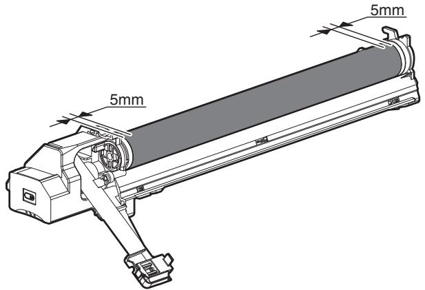
[Mesures correctives]
Si une trace de doigt est fixée par erreur sur la surface du tambour OPC, effectuez les mesures correctives suivantes.
1) Utilisez un chiffon sec pour nettoyer et éliminer la saleté. 2) Appliquez du KYNAR pour empêcher le retournement de la lame.
[Méthode de vérification]
Vérifiez que le tambour OPC est exempt de traces de doigts ou de saletés grasses et que la lame de nettoyage est complètement propre en utilisant la méthode suivante.
- Effectuez une impression d'une image en demi-teintes sur toute la surface d'une feuille A4 (11" x 8,5") et vérifiez que le papier imprimé ne présente aucune anomalie dans l'image.
2. Prévention de l'exposition préalable
Remarque :
- Éviter toute intervention dans un endroit fortement éclairé.
- Ne pas exposer l'appareil à la lumière pendant une longue durée.
- Couvrir le tambour OPC avec un matériau opaque à la lumière. (Si vous utilisez du papier, utilisez environ 10 feuilles pour bloquer la lumière.)
[Contremesures]
Si le tambour OPC a été exposé par erreur à une lumière excessive (exposition préalable), appliquez les contremesures suivantes.
1) Imprimez des images en demi-teintes sur toute la surface d'une feuille A4 (11" x 8,5"), et vérifiez qu'il n'y a pas de zone de densité irrégulière dans la section précédemment exposée. 2) Les dommages dus à une exposition préalable peuvent être réparés en laissant le tambour OPC au repos pendant plusieurs heures. Si, toutefois, les images ne sont pas récupérées, remplacez le tambour OPC.
(1) Tambour
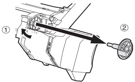
Remarque : lors de l'installation de l'unité de traitement dans l'unité principale après le remplacement du tambour, il se peut que l'unité de traitement ne puisse pas être installée en raison de la position de l'accouplement d'entraînement du tambour. Dans ce cas, faites pivoter le tambour d'environ 45 degrés et réinstallez-le.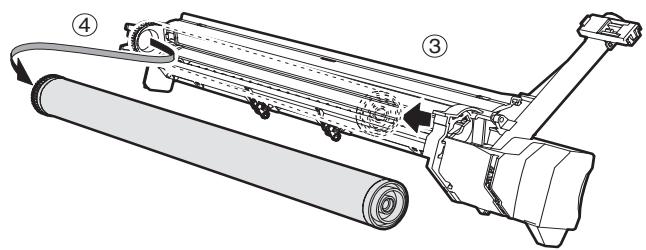
(2) Section tambour
a. Chargeur principal
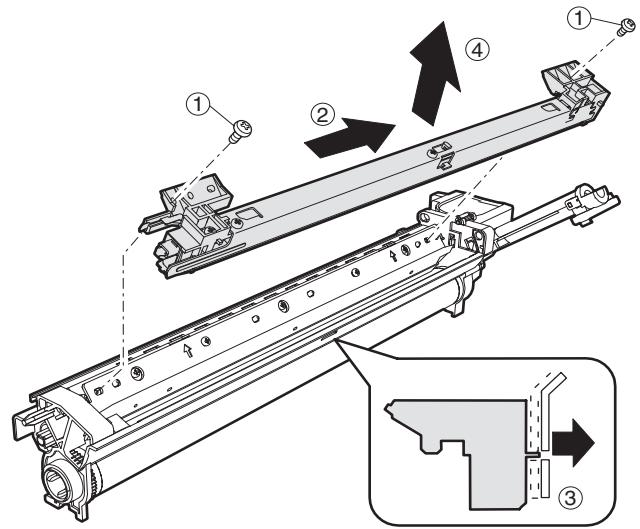
b. Raclette de nettoyage
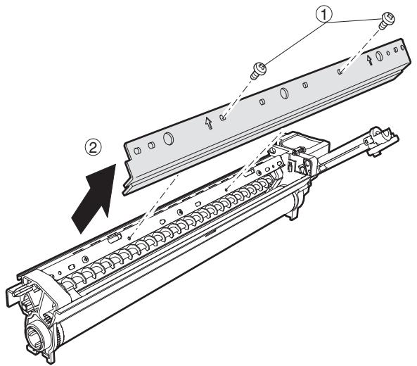
c. Cadre du tambour
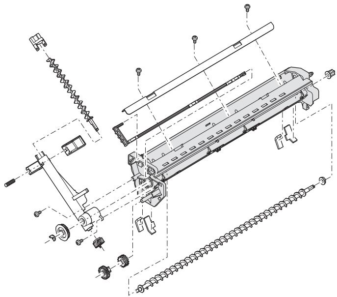
d. Moquette avant/arrière. Remarque : si elle gêne le mouvement de la raclette, remplacez-la et fixez-en une nouvelle.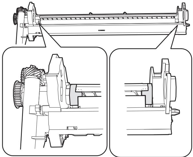
e. Griffe de séparation
Démontage* Tenez l'extrémité de la griffe de séparation et retirez-la.
Assemblage : Appuyez sur le centre du cliquet de séparation et installez-le.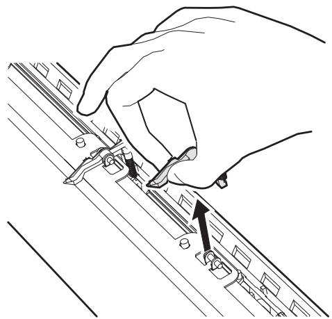
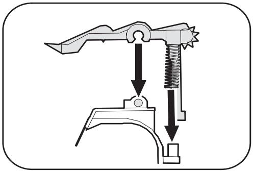
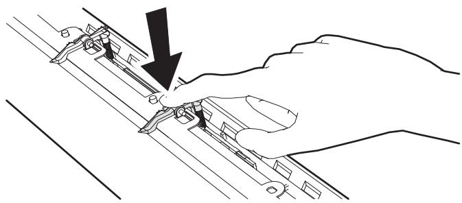
B. Section de développement
(1) Développeur : Faites tourner le rouleau MG pour évacuer le développeur.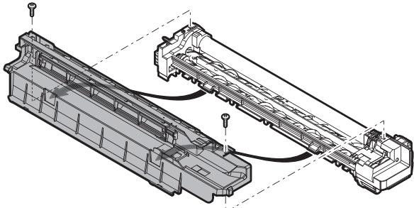
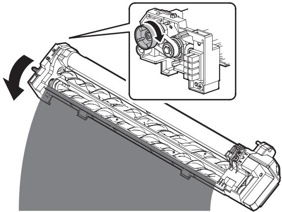
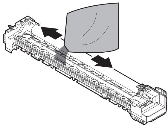
(2) Unité de filtre à toner
Avec le guide AS (couvercle) retiré, remplacez-le.
Lors du remplacement, nettoyez le guide AS.

(3) Feuille latérale DV F / Feuille latérale DV R [Référence de fixation des feuilles latérales DV F/R]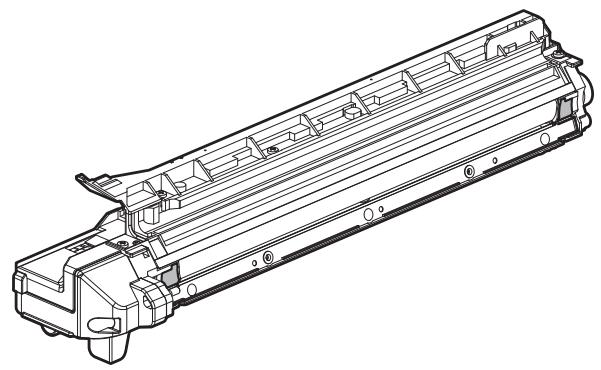
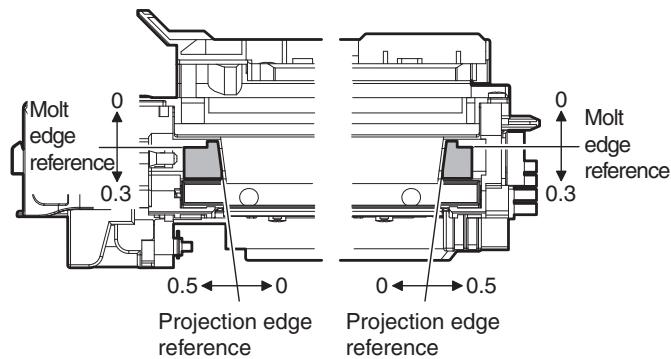
(4) Lame DV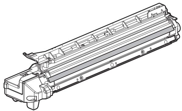
[Référence de fixation de la lame DV]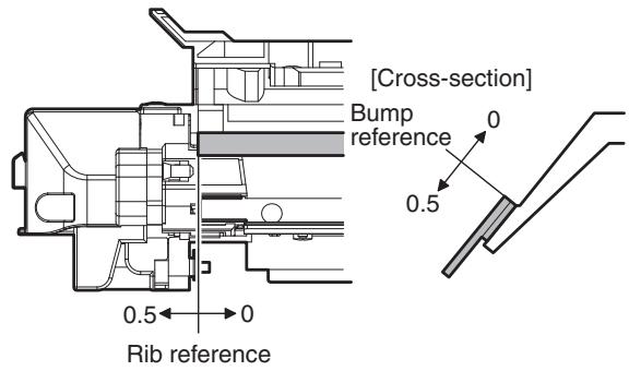
(5) Capteur de toner
- Le nettoyage du capteur doit être effectué après avoir évacué le DV usagé lors du remplacement du DV.
- Sans retirer le rouleau MG, utilisez un chiffon de déchets pour retirer le toner de la surface du capteur dans le sens de la flèche.
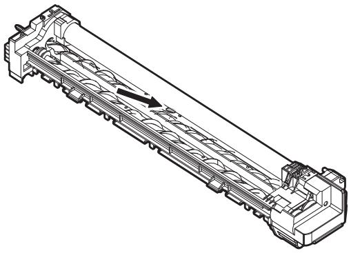
- Nettoyez le capteur uniquement après avoir retiré le DV usagé lors du remplacement du DV.
C. Section de fusion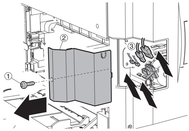
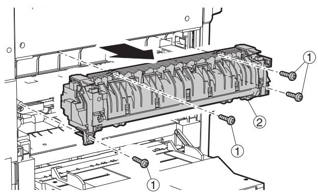
(1) Thermostat : Remarque : lors de la fixation du faisceau de la lampe et du thermostat, le couple de serrage des vis (4 positions) est de 6 à 9 kgs.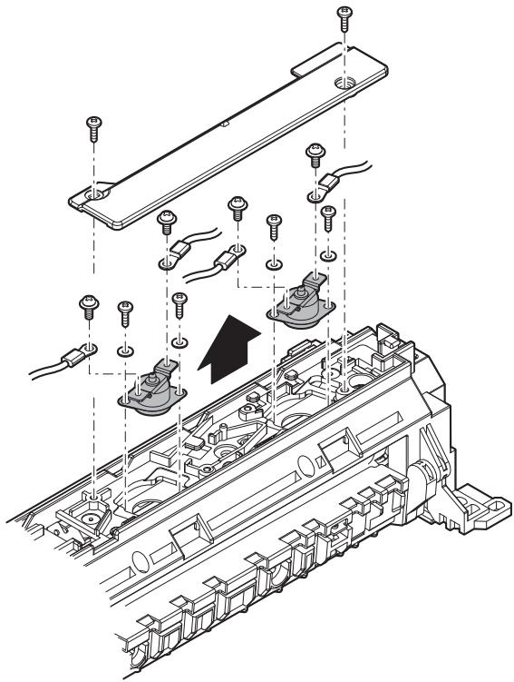
(2) Thermistor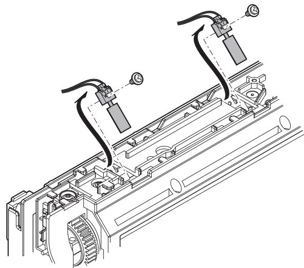
(3) Paper guide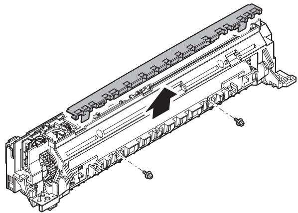
(4) Fusing separation pawl (lower)
(5) Lower heat roller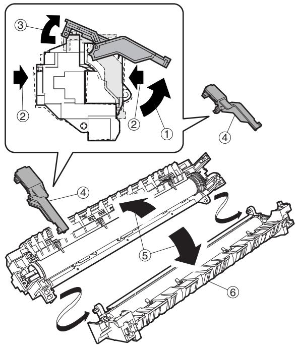
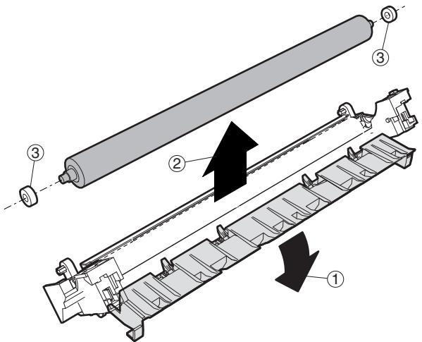
(6) Heater lamp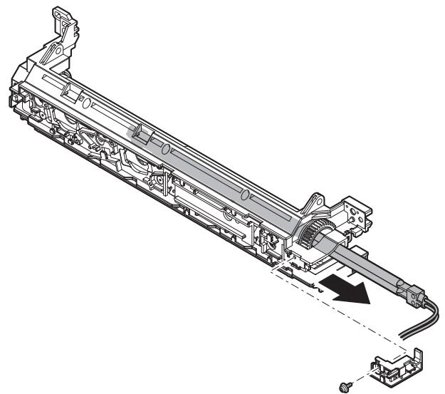
(7) Upper cleaning pad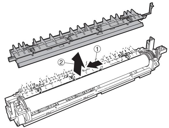
(8) Fusing separation pawl (upper)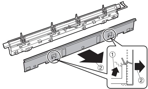
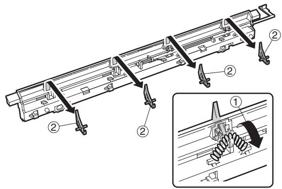
(9) Upper heat roller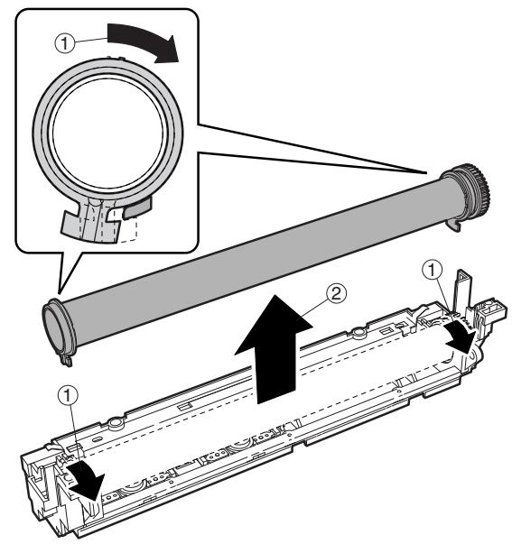
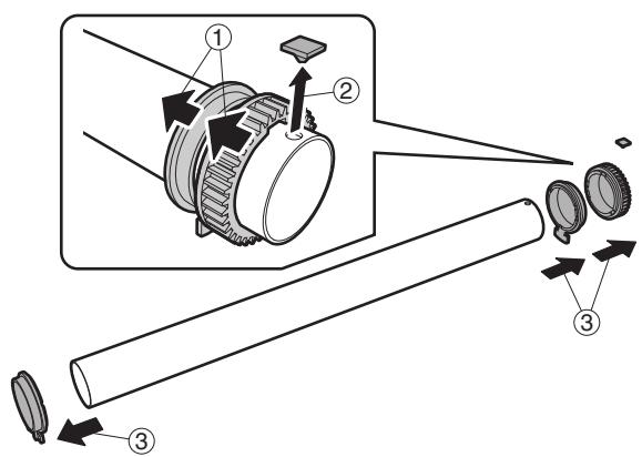
(10) Thermistor cleaning pad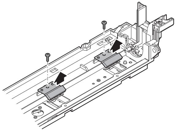
D. Optical section
(1) CCD unit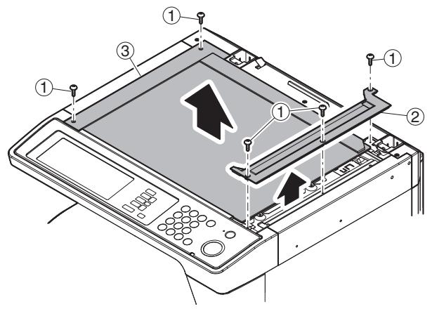
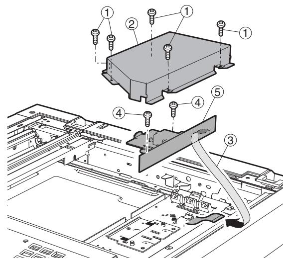
(2) Lamp unit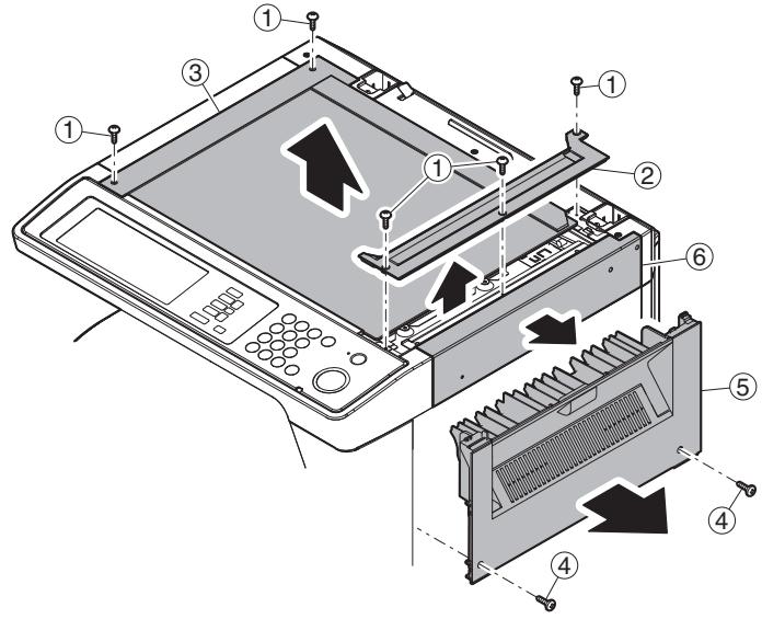
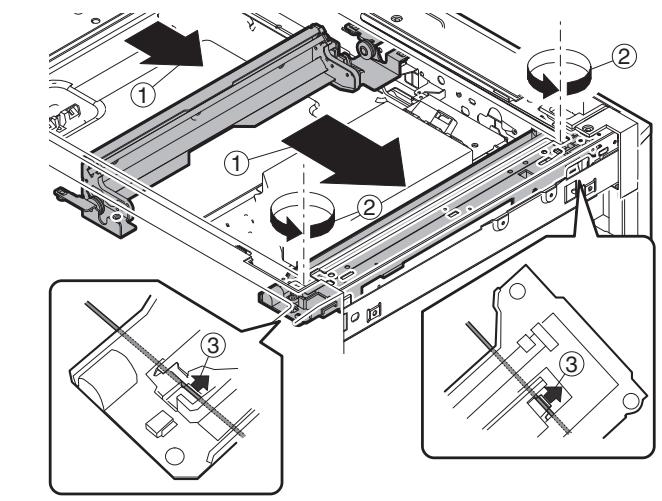
a. Lamp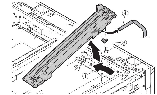
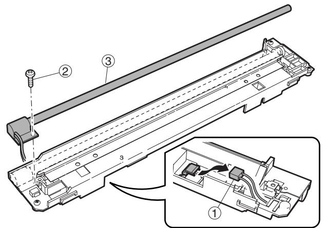
b. PWB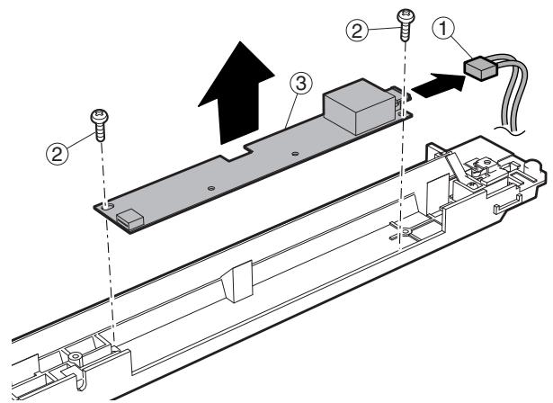
c. Wire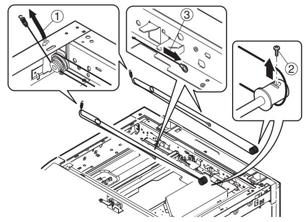
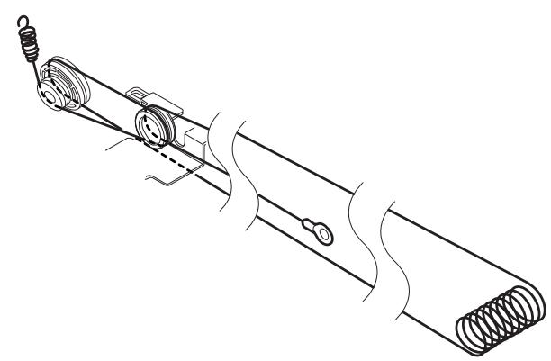
d. Moteur du miroir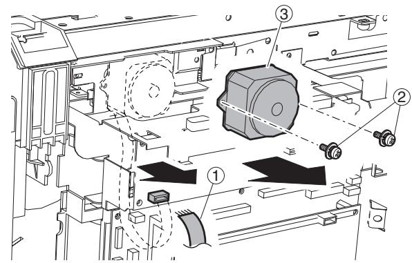
E. Section d'alimentation papier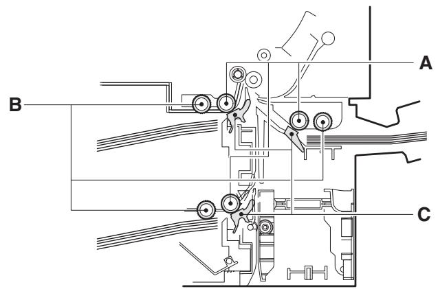
| A | Paper feed roller |
| B | Pickup roller |
| C | Separation sheet |
(1) Électrovanne d'alimentation papier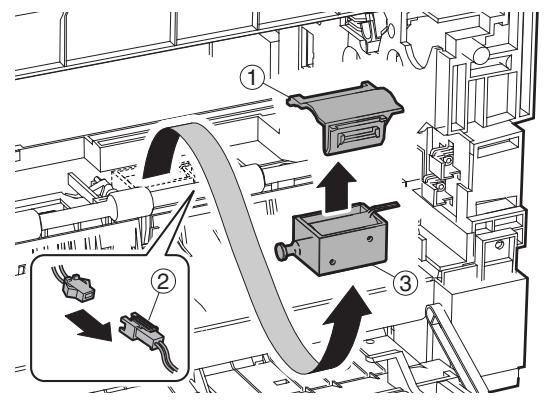
(2) Carte PWB du capteur de bac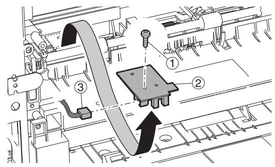
(3) Capteur d'entrée manuelle/Capteur de bac vide manuel (4) Alimentation papier manuelle multiple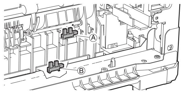
a. Rouleau d'alimentation/rouleau de préhension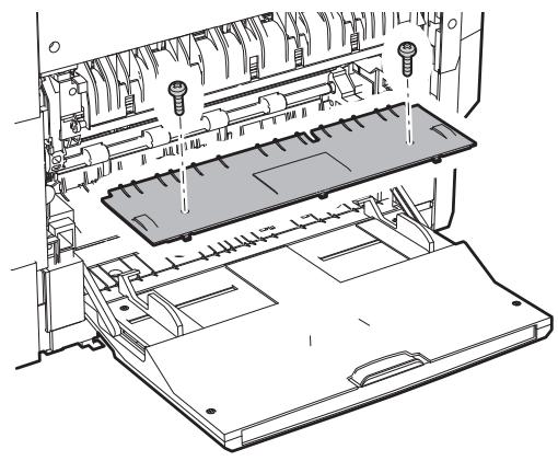
Installation*Installer de sorte que le bras de transmission de came (1) se trouve sous le bras de rouleau (2).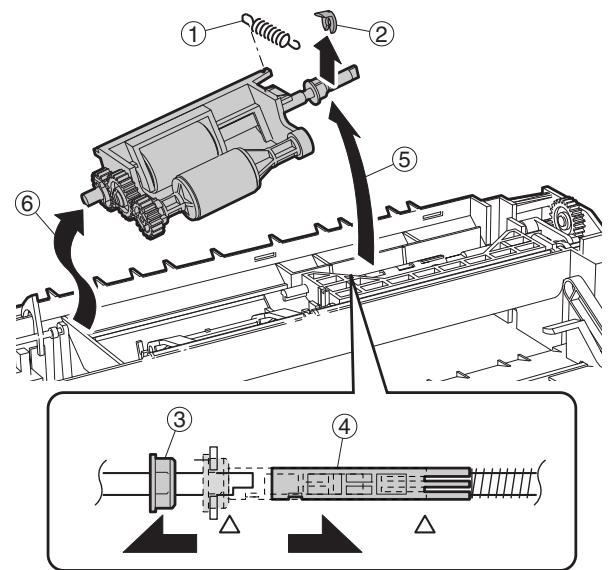
b. Capteur d'inversion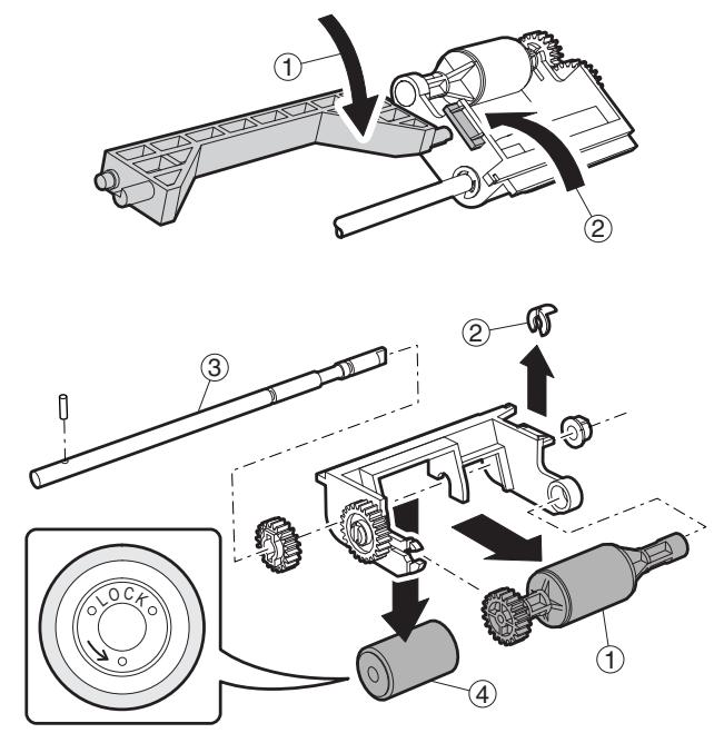
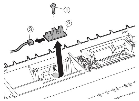
c. Feuille de séparation * Appliquer légèrement de la graisse GP501MR (UKOG-0012QSZZ) autour de l'axe. Un grain de riz pour chaque.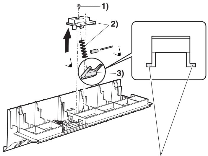
d. Embrayage/électrovanne (Embrayage)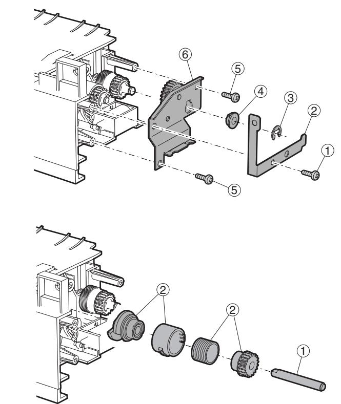
(Électrovanne)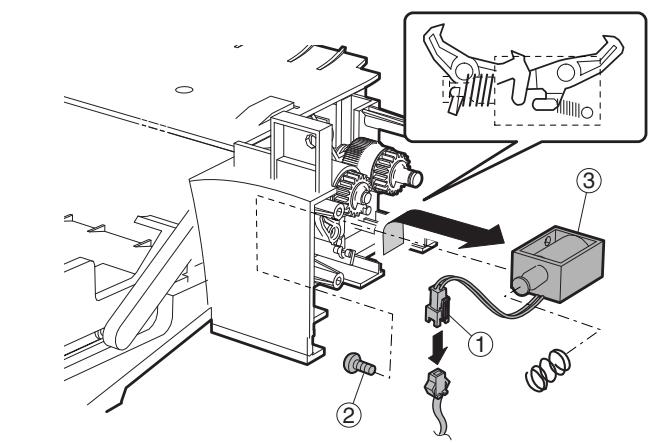
(Embrayage)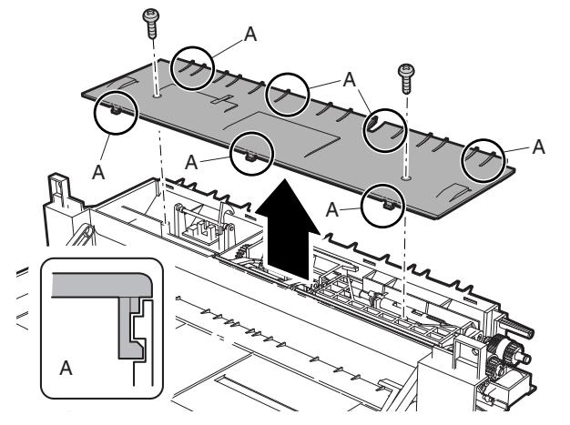
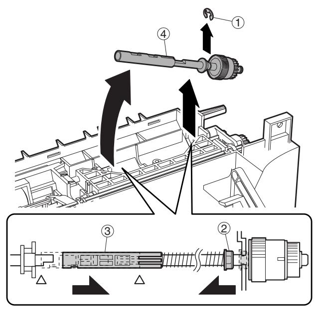
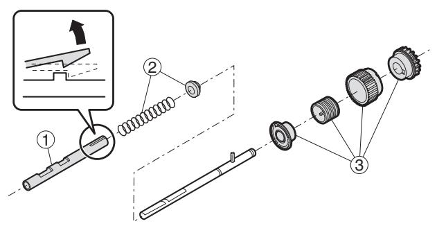
(5) Alimentation papier du bac supérieur de 500 feuilles a. Rouleau d'alimentation/rouleau de préhension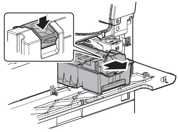
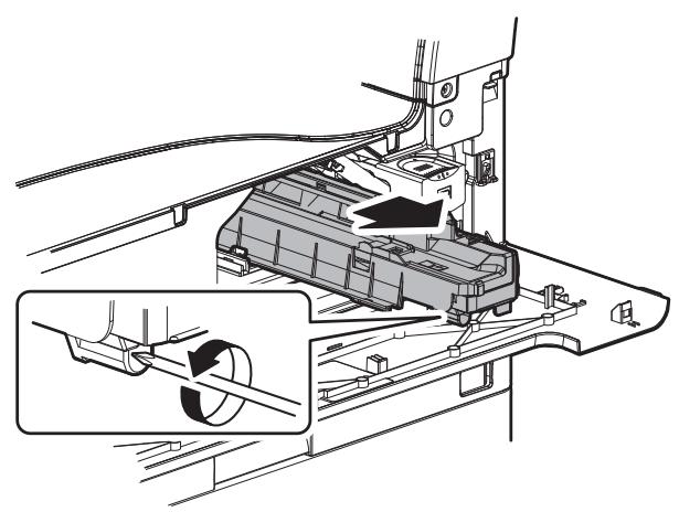
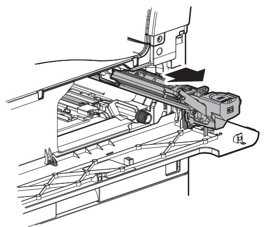
Remarque : Avec la cartouche de toner installée, ne pas incliner ni secouer la cartouche de développement.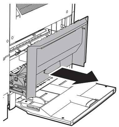
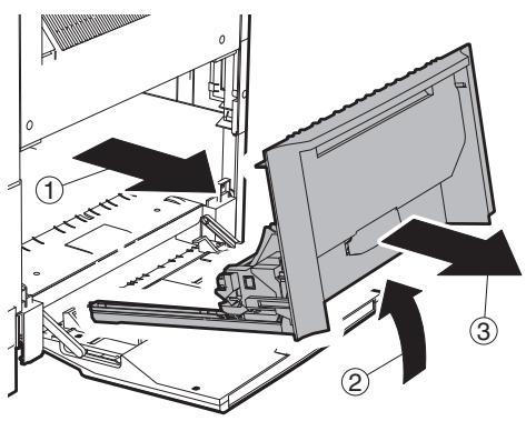
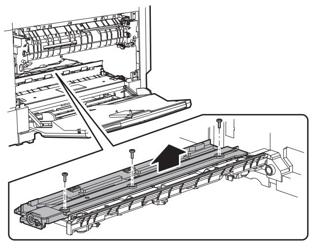
* Lors du remplacement, veiller à ne pas faire adhérer de la graisse conductrice (noire) à la section d'entraînement. Appliquer légèrement de la graisse GE676 (UKOG-0013QSZZ) sur le bossage du tambour.

b. Feuille de séparation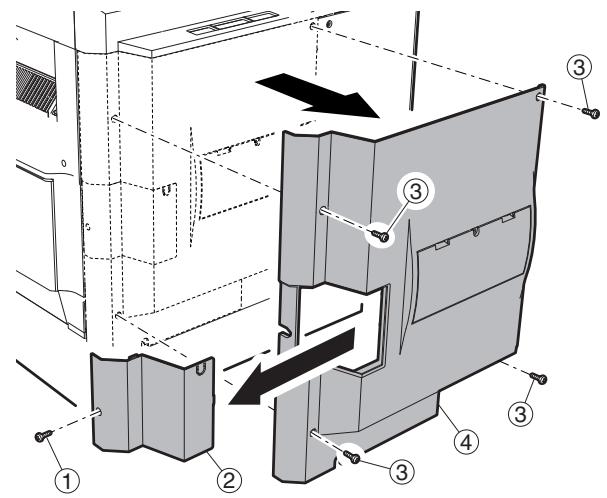
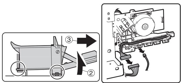
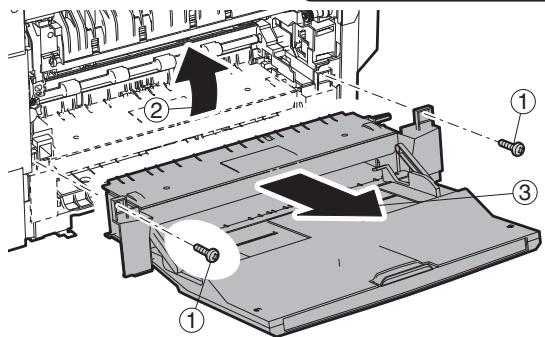
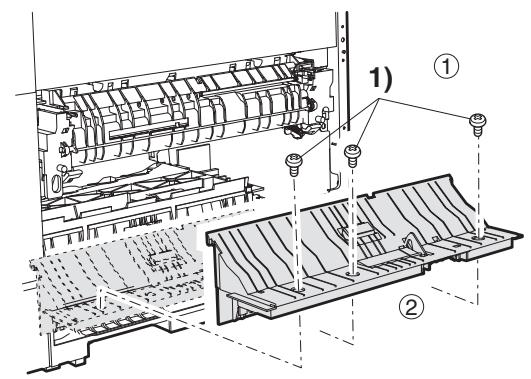
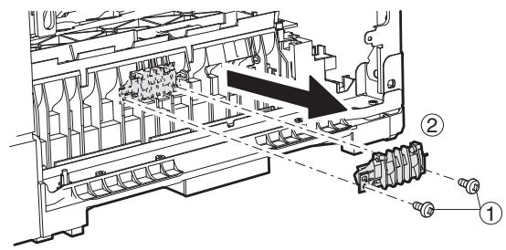
* Appliquer légèrement de la graisse GP501MR (UKOG-0012QSZZ) autour de l'axe. Un grain de riz pour chaque. La graisse ne doit pas sortir lors de l'assemblage.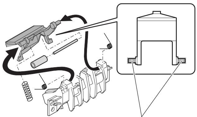
(6) Alimentation papier du bac de 500 feuilles inférieur
a. Rouleau d'alimentation / rouleau de reprise
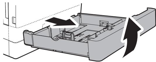
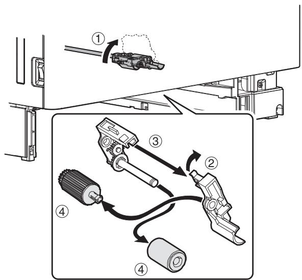
b. Feuille de séparation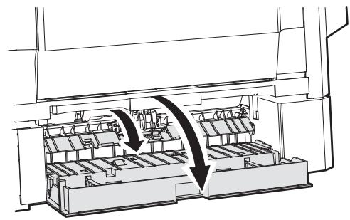
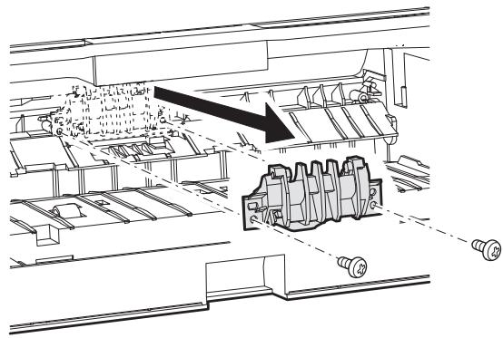
* Appliquer légèrement de la graisse GP501MR (UKOG-0012QSZZ) autour de l'axe. Un grain de riz pour chaque. La graisse ne doit pas sortir lors de l'assemblage.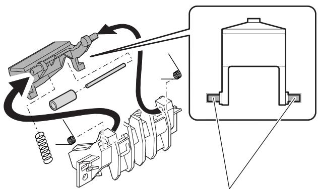
c. Unité de levage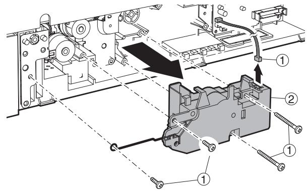
d. Embrayage de transport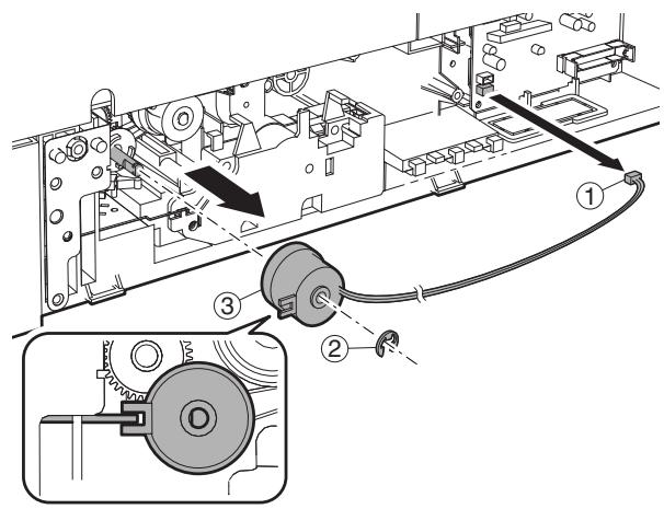
e. Embrayage d'alimentation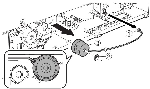
f. Embrayage de transport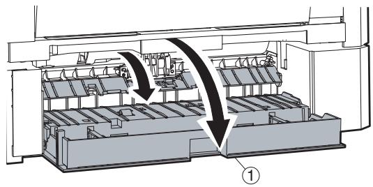
g. Électrovanne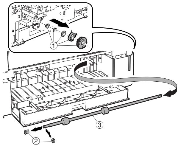
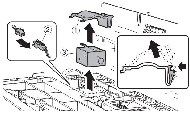
h. Carte PWB du capteur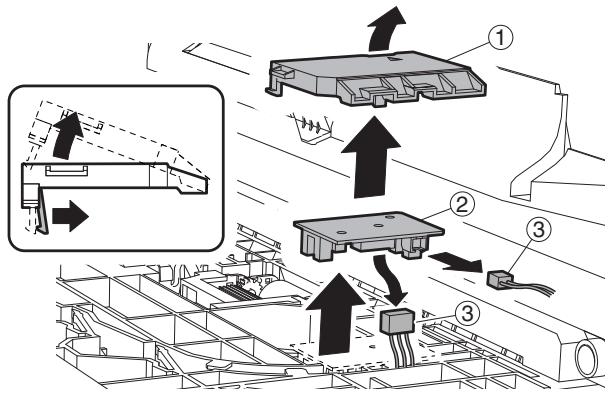
F. Unité de porte latérale
(1) Unité de rouleau de transport * Vérifier que les deux ressorts sont correctement insérés dans les bossages de l'unité de rouleau de transfert.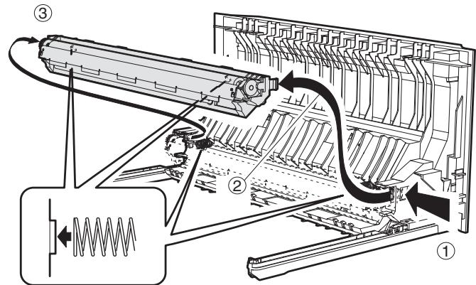
(2) Rouleau de transport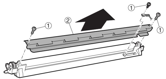
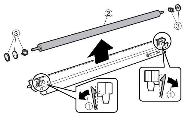
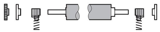
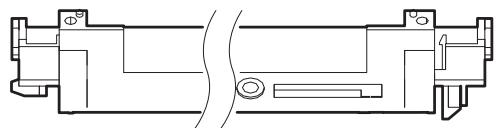
(3) Rouleau de transport DUP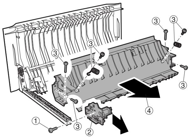
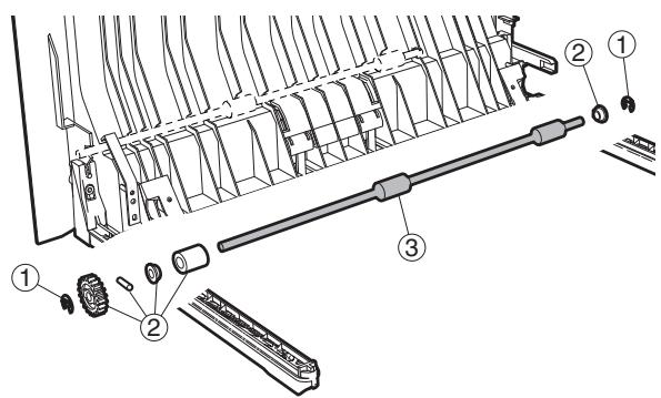
(4) Moteur DUP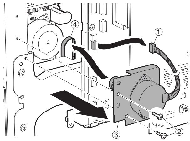
G. Première unité de sortie papier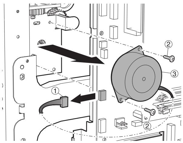
(1) Ventilateur de refroidissement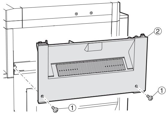
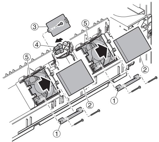
(2) Rouleau de transport/sortie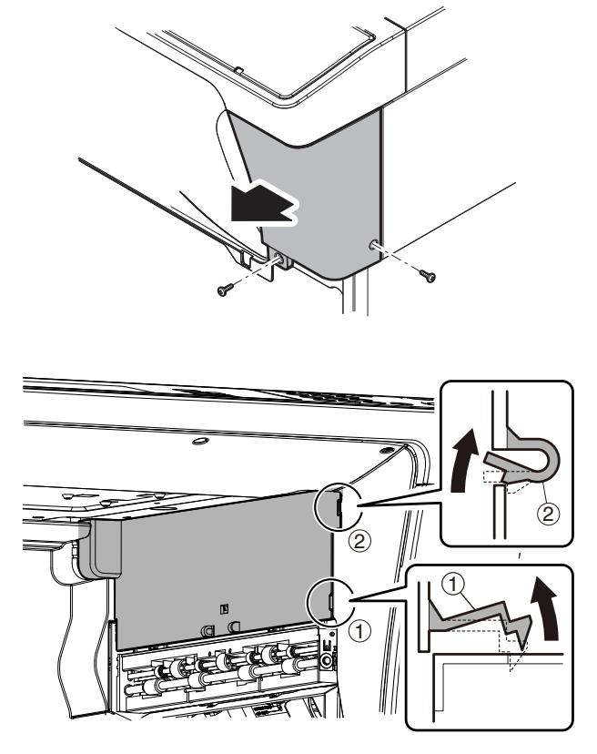
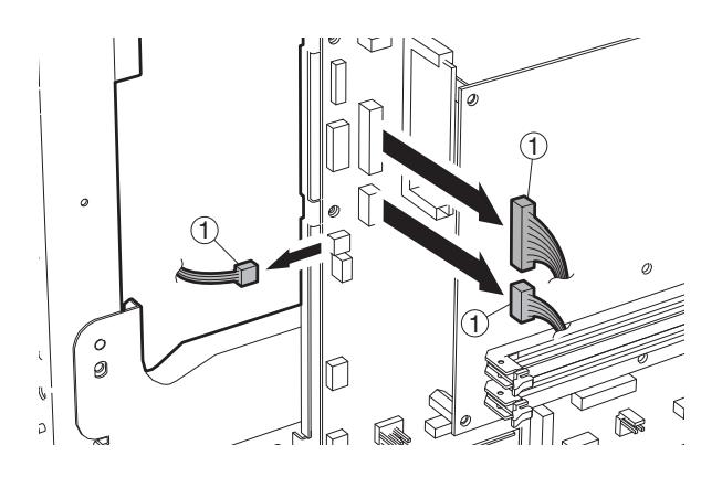
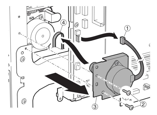
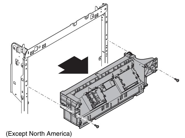
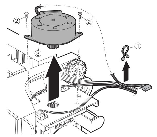
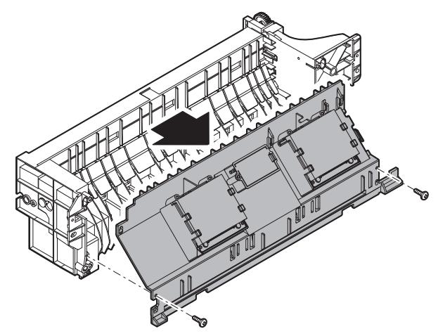
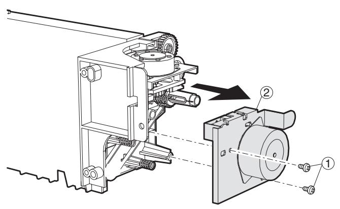
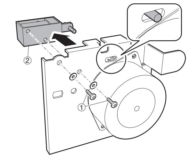
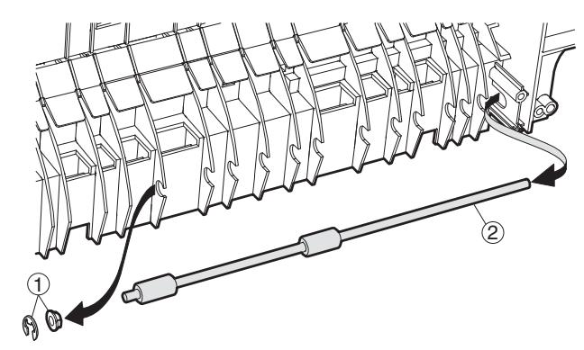
Remarque : Vérifier que l'arbre de la bobine est dans le support de porte, et fixer avec la vis.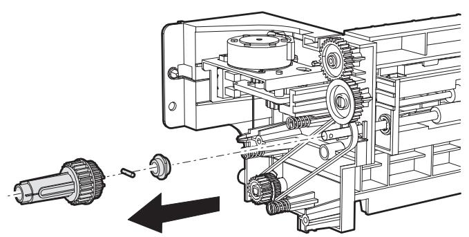
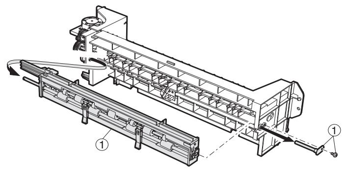
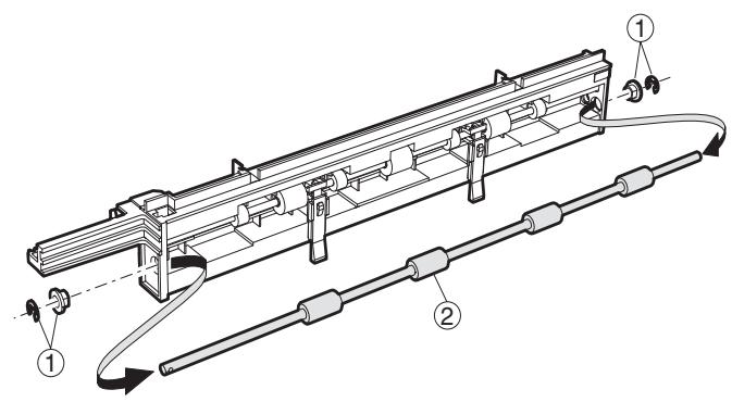
H. Unité laser
Remarque : Ne pas démonter l'unité LSU.
(1) LSU
1) Mettre la machine hors tension et débrancher la fiche d'alimentation de la prise. 2) Retirer le panneau latéral gauche et le bac de sortie. 3) Débrancher le connecteur LSU et retirer les vis de fixation pour retirer le LSU.
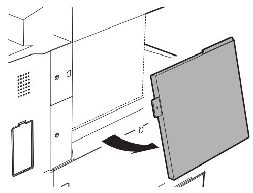
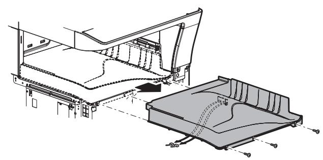
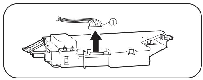
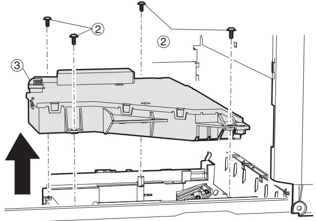
I. Unité d'alimentation
(1) Source d'alimentation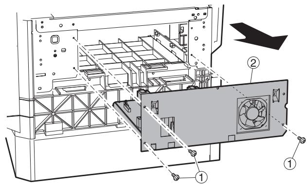
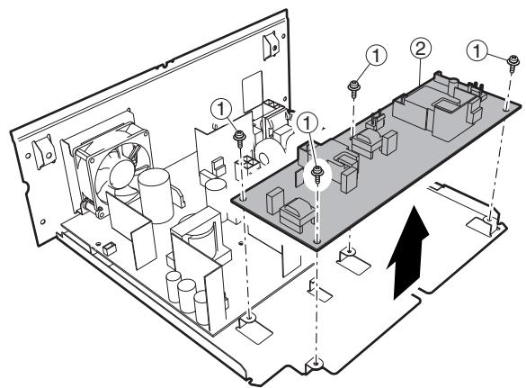
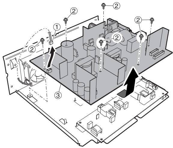
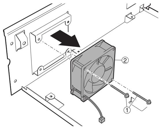
J. PWB
(1) PWB d'option CN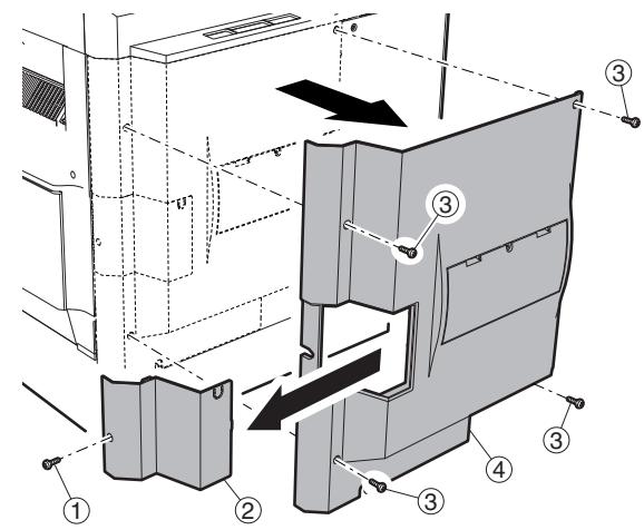
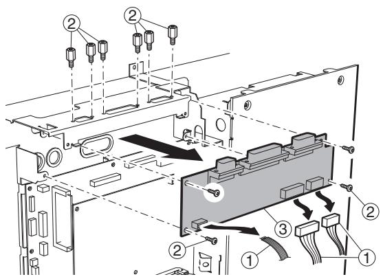
(2) PWB IMC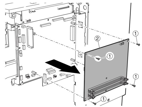
(3) MCUPWB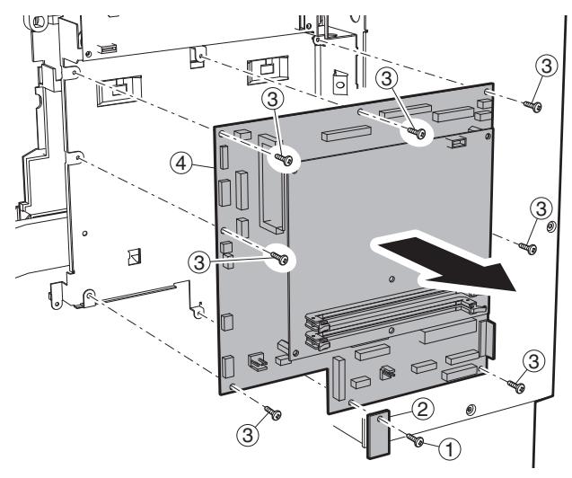
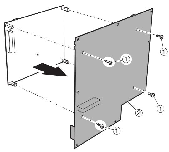
(4) Carte mère PWB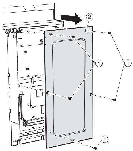
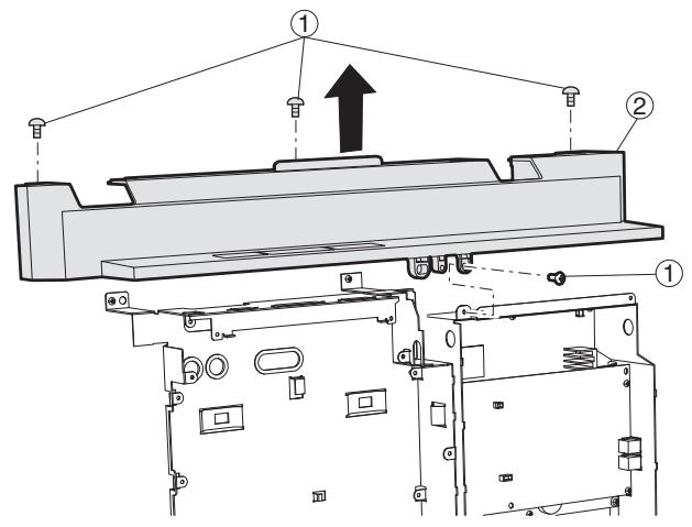
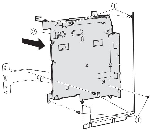
(5) Deuxième interface PWB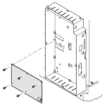
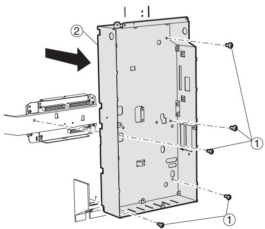
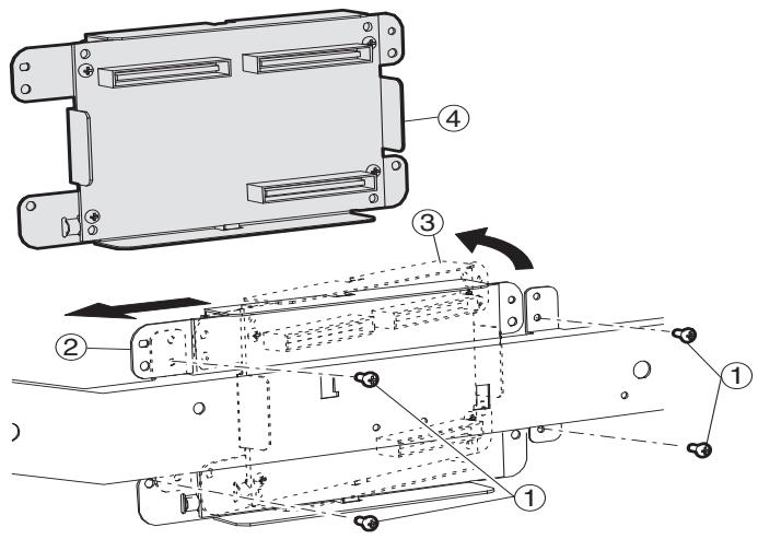
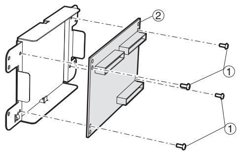

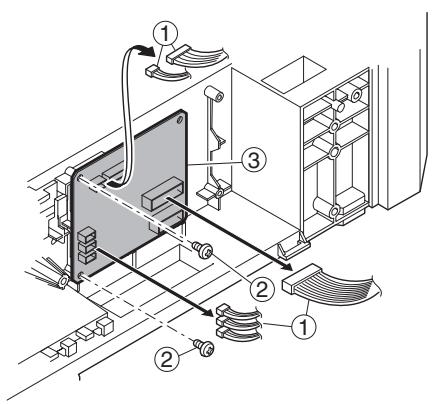
K. Filtre à ozone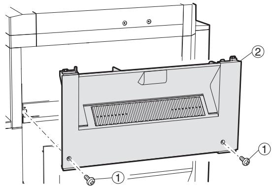
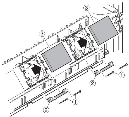
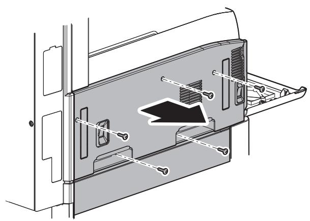
L. Section d'entraînement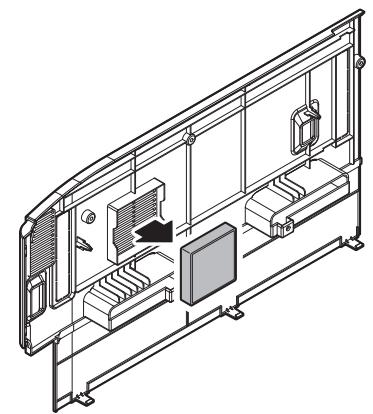
(1) Moteur d'inversion DUP (2) Moteur d'entraînement principal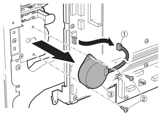
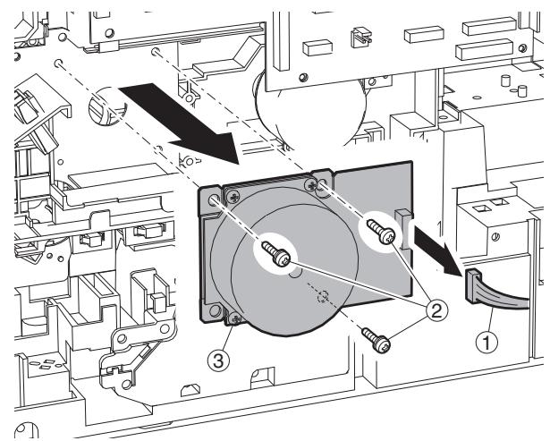
(3) Moteur du toner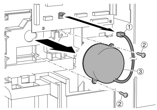
(4) Embrayage de transport PS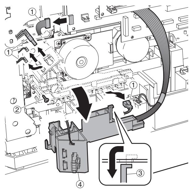
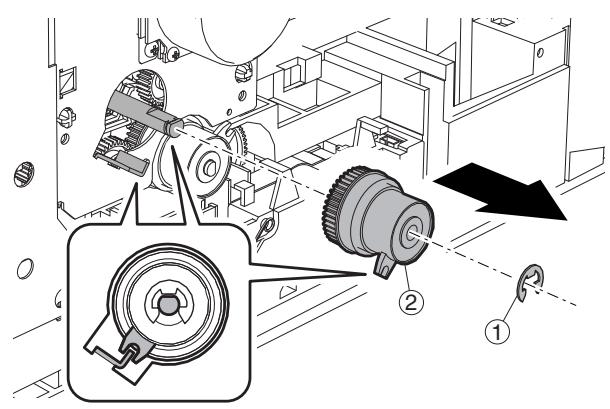
(5) Embrayage d'alimentation papier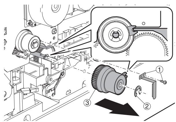
(6) Unité d'entraînement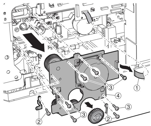
Unité d'entraînement (partie d'application de graisse)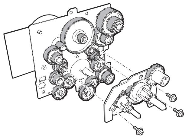
(7) Moteur de levage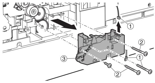
M. Section de transport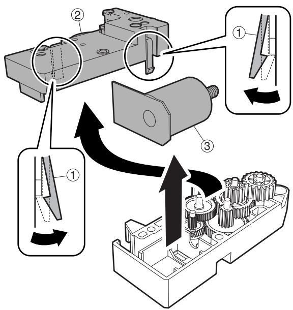
(1) Rouleau de transport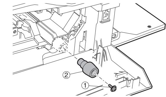
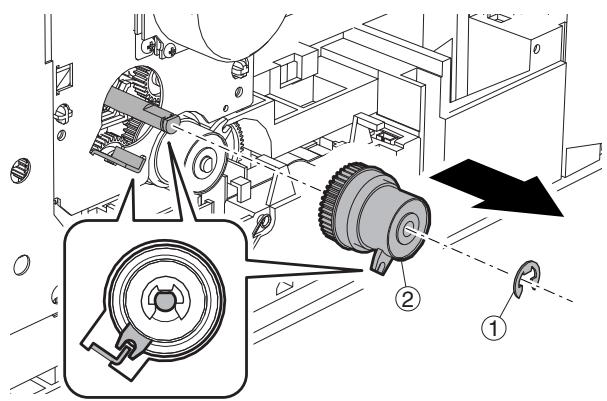
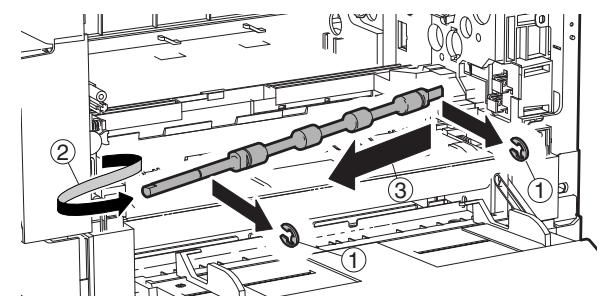
N. Section d'opération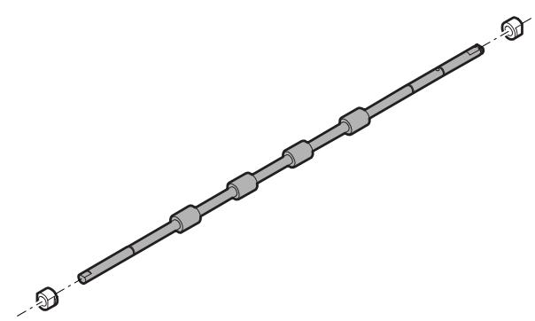
(1) Section de fonctionnement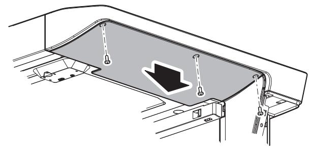
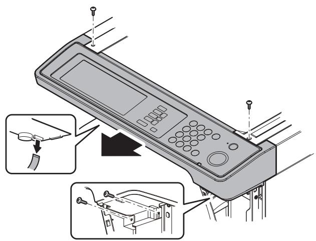
(2) Carte OPU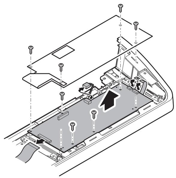
(3) Carte clavier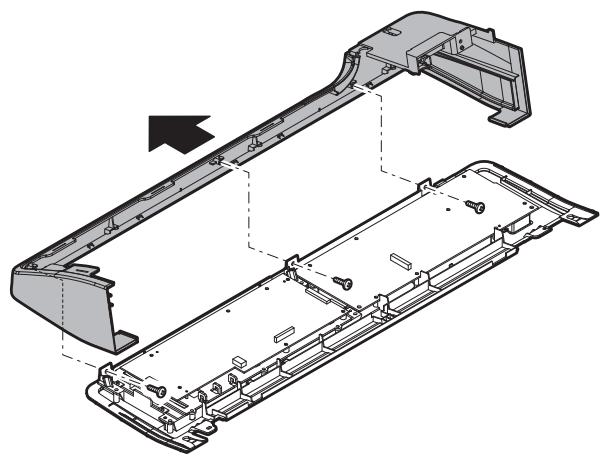
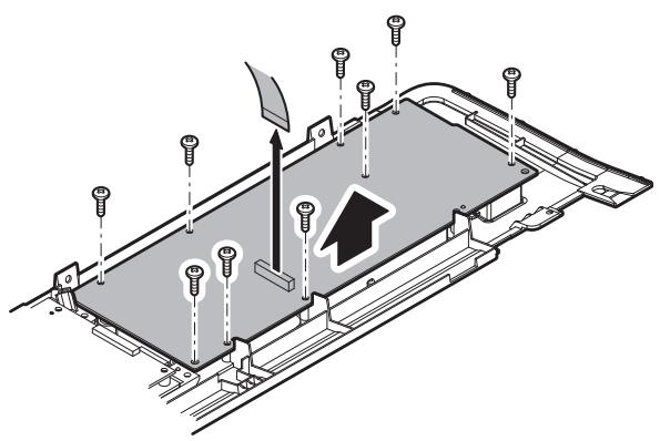
(4) Unité LCD O. Interrupteur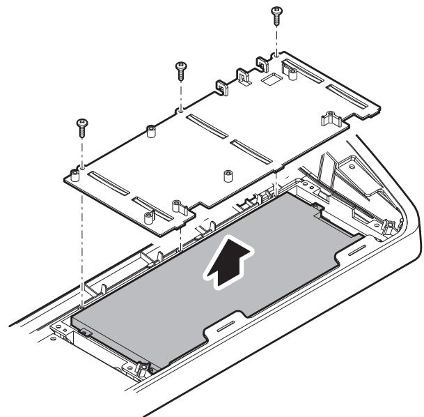
(1) Interrupteur d'alimentation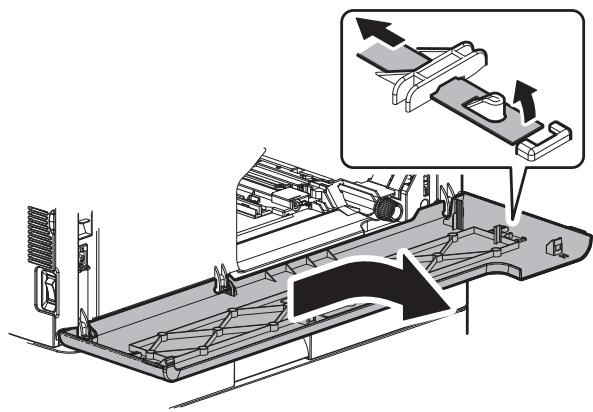
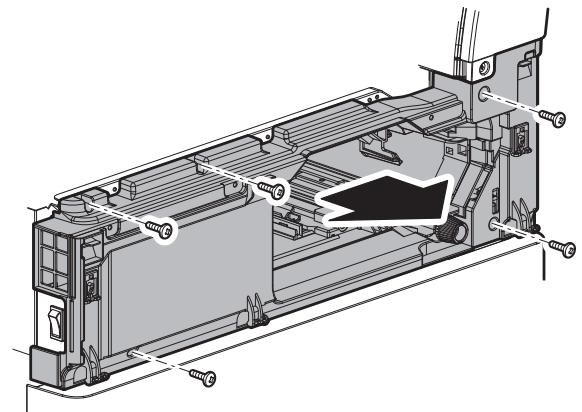
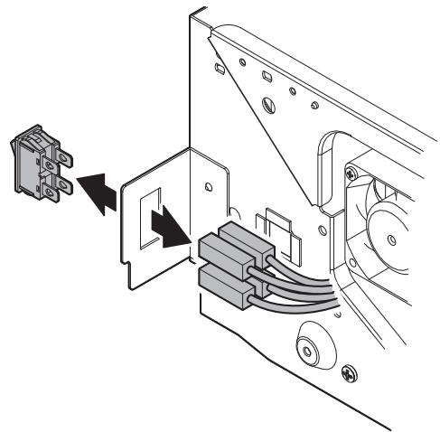
P. RSPF (1) Section plateau de documents a. Unité plateau de documents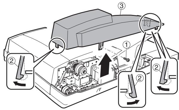
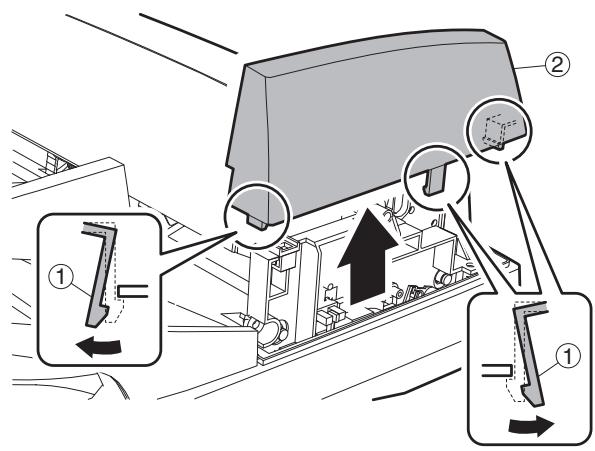
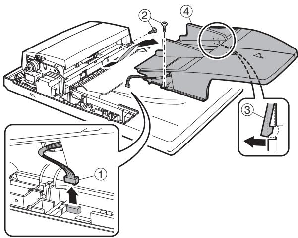
b. Capteur de longueur de document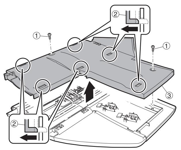
(2) Section unité d'alimentation papier a. Embrayage d'alimentation papier b. Rouleau de préhension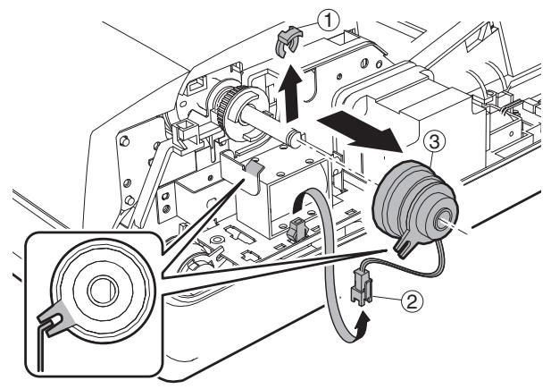
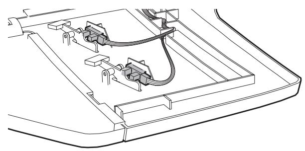
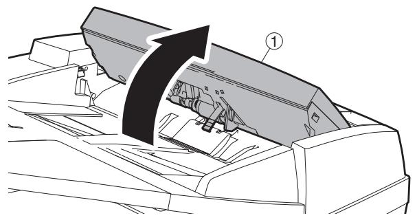
c. Carte de résistance de largeur de document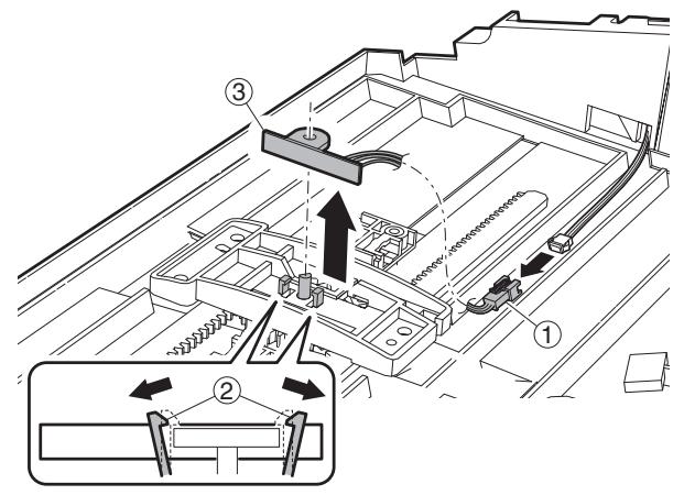
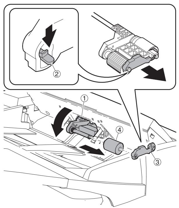
c. Rouleau d'alimentation papier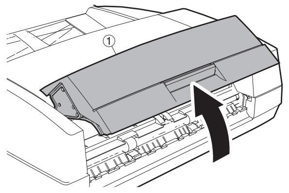
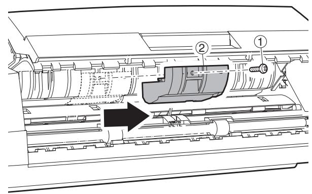
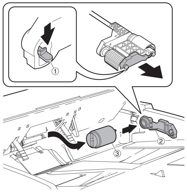
d. Unité d'alimentation papier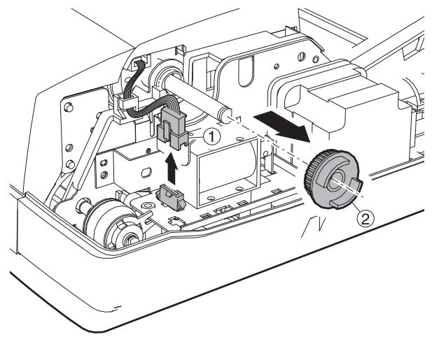
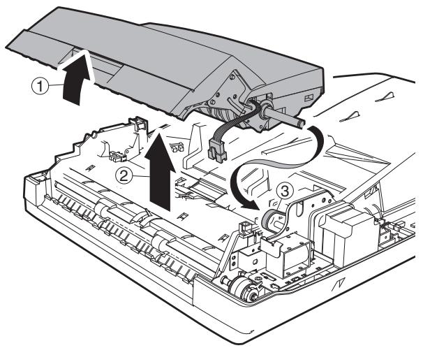
e. Feuille de séparation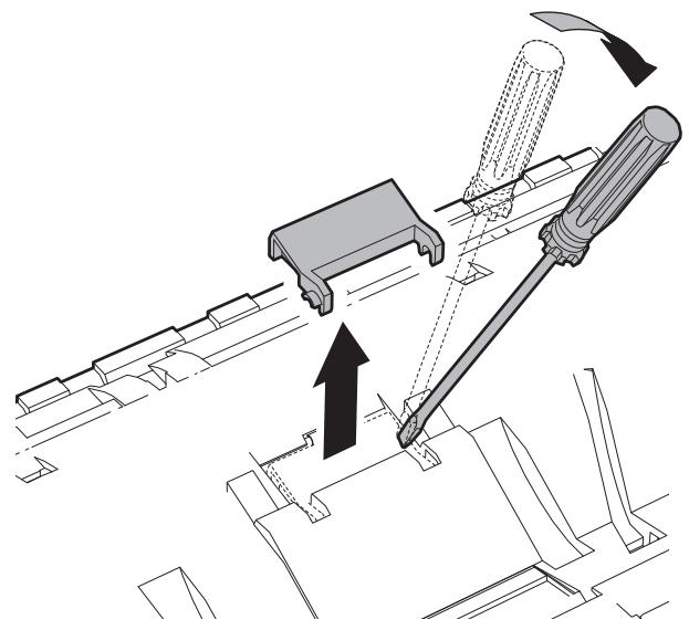
f. Capteur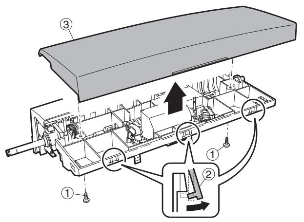
b. Embrayage PS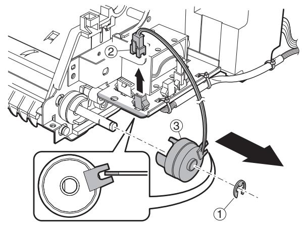
c. Électrovanne de libération de pression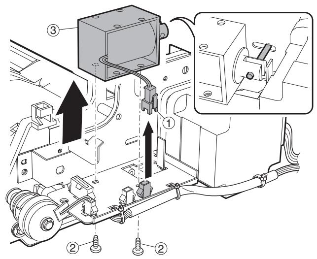
(3) Section transport a. Unité de transport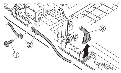
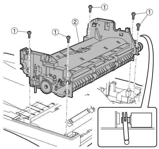
d. Moteur RSPF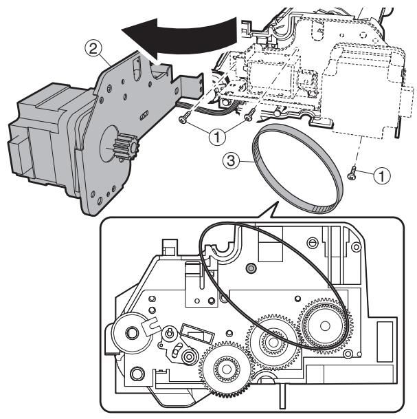
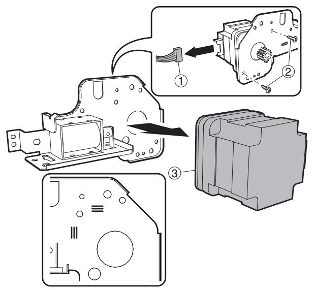
Le moteur est positionné à l'aide du gabarit. Utilisez la marque lors de son assemblage à la position d'origine.
e. Rouleau de transport
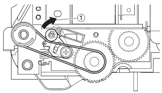

f. Rouleau
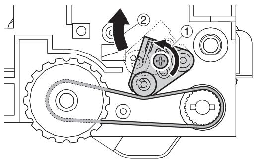
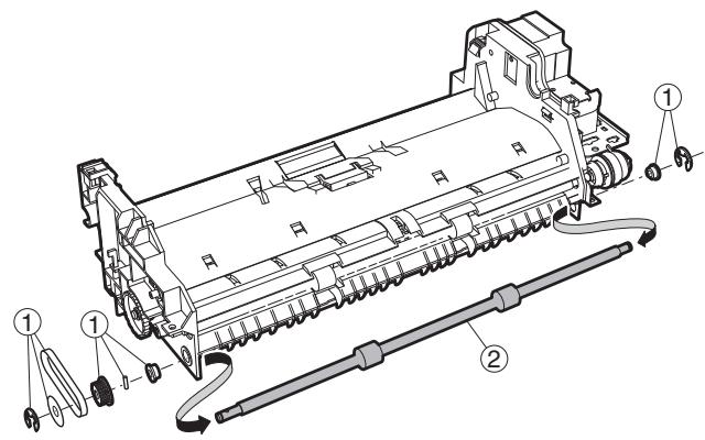
g. Capteur
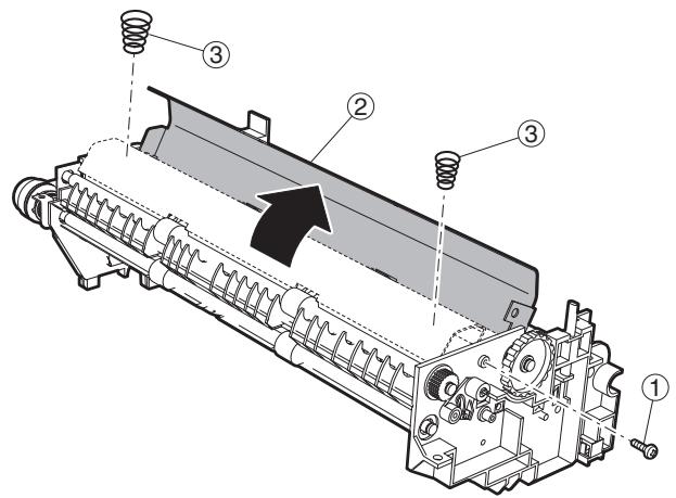
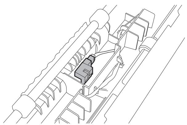
h. Rouleau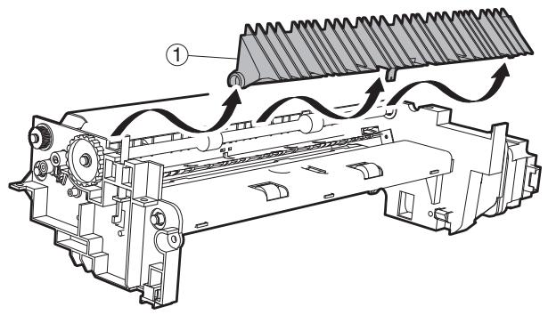
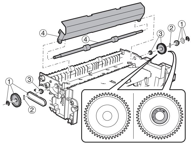
i. Rouleau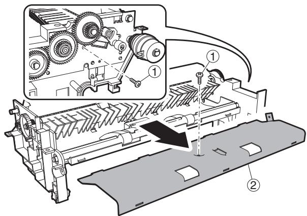
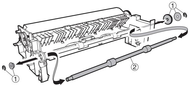
(4) Section de base a. PWB d'interface b. Électroaimant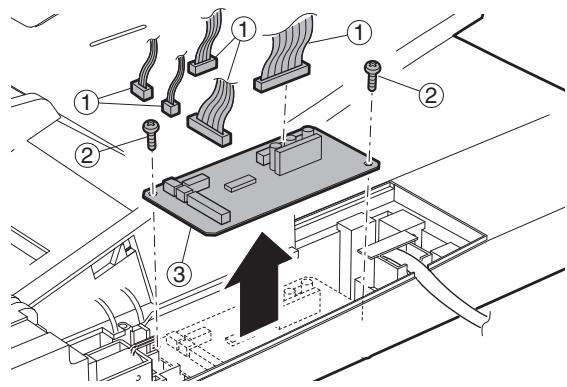
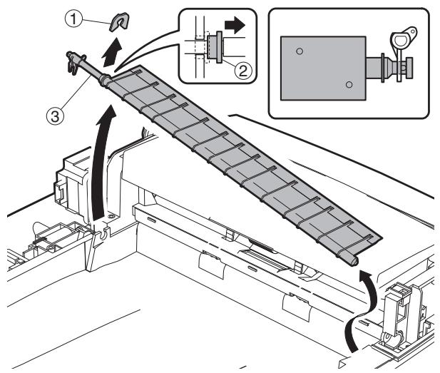
c. Capteur de livre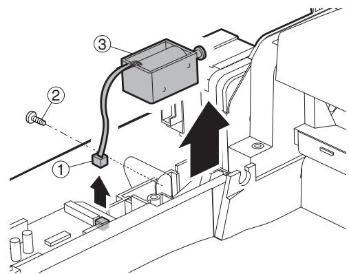
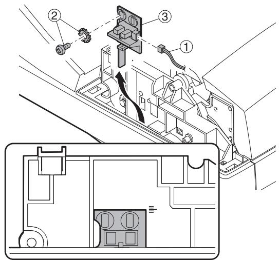
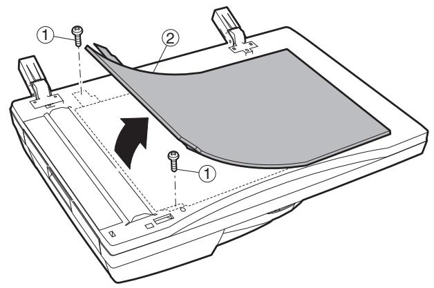
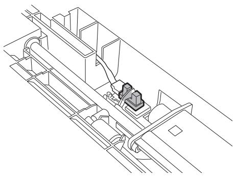
3. Autres éléments connexes
A. Remise à zéro du compteur
| Item | SIM | Remarks |
| Maintenance cycle setting | SIM 21-1 | |
| Jam/trouble counter clear | SIM 24-1 | |
| Paper feed counter clear | SIM 24-2 | |
| Scan/Stapler counter clear | SIM 24-3 | |
| Maintenance counter clear | SIM 24-4 | * |
| Developing counter clear | SIM 24-5 | After execution of SIM25-2, this counter is cleared. |
| Copy counter clear | SIM 24-6 | |
| Drum counter clear | SIM 24-7 | At drum replacement |
| Printer, IMC, Duplex, other counter clear | SIM 24-9 | |
| FAX counter clear | SIM 24-10 | |
| Scanner mode counter clear | SIM 24-15 |
- Modèle 31 feuilles : lorsque le message de maintenance s'affiche, remplacez la pièce consommable ayant atteint le nombre de feuilles de maintenance, puis remettez à zéro uniquement le compteur de la pièce remplacée.
[9] MISE À JOUR DU FIRMWARE
1. Procédure de mise à jour du firmware
(Éléments nécessaires pour la mise à jour)
A. Un ordinateur personnel B. Un câble croisé RS232C (D-sub 9 broches vers D-sub 9 broches, ou D-sub 25 broches vers D-sub 9 broches) C. Un logiciel pour la mise à jour de version
(Carte cible)
1. Carte MCU 2. Carte panneau 3. Carte IMC 4. Carte finisseur
Aperçu de la procédure de mise à jour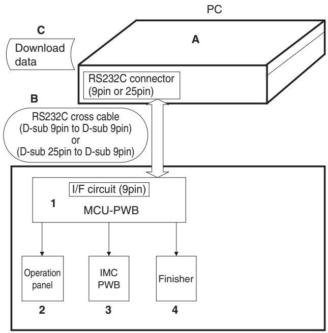
Préparez les fichiers suivants nécessaires à la mise à jour du programme
- Logiciel de maintenance : maintenance.exe
- Fichier de module Andromeda : ProcModelR.mdl
- Pilote de l'outil de maintenance : SFZEJENU.inf
A. Méthode de mise à jour du firmware (pour le copieur et le firmware fax)
Les procédures opérationnelles suivantes concernent :
- Firmware copieur, firmware fax
1) Assurez-vous que le copieur est éteint, puis connectez-le au PC avec le câble de téléchargement au préalable. 2) Démarrez le programme de maintenance sur le PC. Sélectionnez le nom du modèle dans la boîte de dialogue de sélection du modèle.
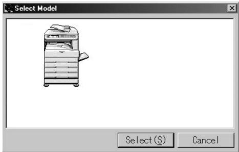
3) Assurez-vous que seul l'arbre "Printer Control Board" est visible sous "Simulation Command List".
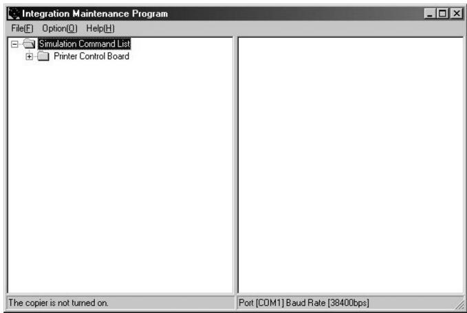
4) Allumez le copieur. La machine démarre en mode téléchargement. 5) Un arbre supplémentaire sera visible lors du téléchargement du programme de maintenance sur le PC. * Assurez-vous de démarrer le programme de maintenance avant d'allumer la machine.
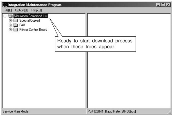
6) Lors du téléchargement du firmware du copieur, développez "Spécial (Copieur)", puis double-cliquez sur "Téléchargement de toutes les zones de données".

7) Sélectionnez le fichier de téléchargement (.dat), puis appuyez sur le bouton "Ouvrir".
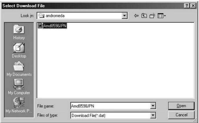
8) La procédure de téléchargement démarre automatiquement.
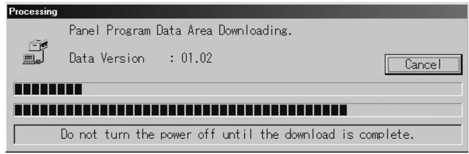
9) Un message de notification "Téléchargement terminé. Vérifiez le panneau du copieur pour vous assurer que le téléchargement est terminé." apparaîtra sur le PC. 10) Fermez le programme de maintenance, puis éteignez le copieur. Rallumez le copieur après avoir débranché la prise.
Ceci est la fin de la procédure de téléchargement.
- Il est possible que le processus de téléchargement ait échoué si le copieur ne démarre pas correctement. Dans ce cas, démarrez le copieur et le programme de maintenance en mode de téléchargement en répétant les étapes 1) à 5). Ensuite, développez "Spécial", puis double-cliquez sur "Confirmer l'état d'erreur". Si un message autre que "Aucune erreur ne s'est produite" apparaît, cela signifie que le téléchargement est incomplet, veuillez donc réessayer.
B. Autres (Dépannage)
Voici les erreurs susceptibles de se produire pendant le processus de téléchargement et la méthode de dépannage.
| No | Warning/errormessage | Detail |
| 1 | Incorrect destination. Continue with the download process? | Destination of download file and copier doesn't match.Possible to select either continue or cancel the job.[TROUBLESHOOTING]To change destination, select "Yes". If not, select "No" and cancel download process. |
| 2 | Incorrect download file. | Invalid download file for the machine is selected, or the file format is not correct.[TROUBLESHOOTING]Confirm the download file. Possibly the improper download file is selected. |
| 3 | No downloadable data included. | Unable to find appropriate data in selected download file.[TROUBLESHOOTING]Confirm the download file. Possibly the improper download file is selected. |
| 4 | This option not available. | Download procedure is executed on uninstalled optional kit.[TROUBLESHOOTING]Confirm installed optional kit.Confirm the download file. Possibly the improper download file is selected. |
| 5 | The data size exceeds the Flash ROM size.Try again with the appropriate size of data. | Panel flash ROM size is not enough to execute download procedure.[TROUBLESHOOTING]Confirm the download file. Possibly the improper download file is selected.Exchange the flash ROM to the one which has more capacity. |
| 6 | Time out error. | Transmission errorUnable to receive data from the machine among the certain period of time.[TROUBLESHOOTING]Restart maintenance program after confirming communication port or communication cable. |
| 7 | Communication (incoming) error. | Incorrect download procedure.The machine did not proceed download procedure correctly.[TROUBLESHOOTING]Restart maintenance program after confirming communication port or communication cable.Make sure the communication device of PC(either COM or parallel) is under right condition. |
| 8 | Checksum error. | Transmission errorThe check sum value of the transmission data is mismatch.[TROUBLESHOOTING]Restart maintenance program after confirming communication device of PC (either COM or parallel) is under right condition. |
| 9 | Error during the download process. Error code: 0xXXXXXXXXX | Download data file operation error.[TROUBLESHOOTING]Restart maintenance program after confirming the selected download file is not abnormal andnot using other application. |
| 10 | An error. [0xXXXXXXXXX] | The error occurred except the above errors.[TROUBLESHOOTING]Restart maintenance program after confirming communication device of PC(either COM or parallel) is under right condition. |
[10] SECTION ÉLECTRIQUE
1. Schéma fonctionnel
A. SCHÉMA FONCTIONNEL DU SYSTÈME
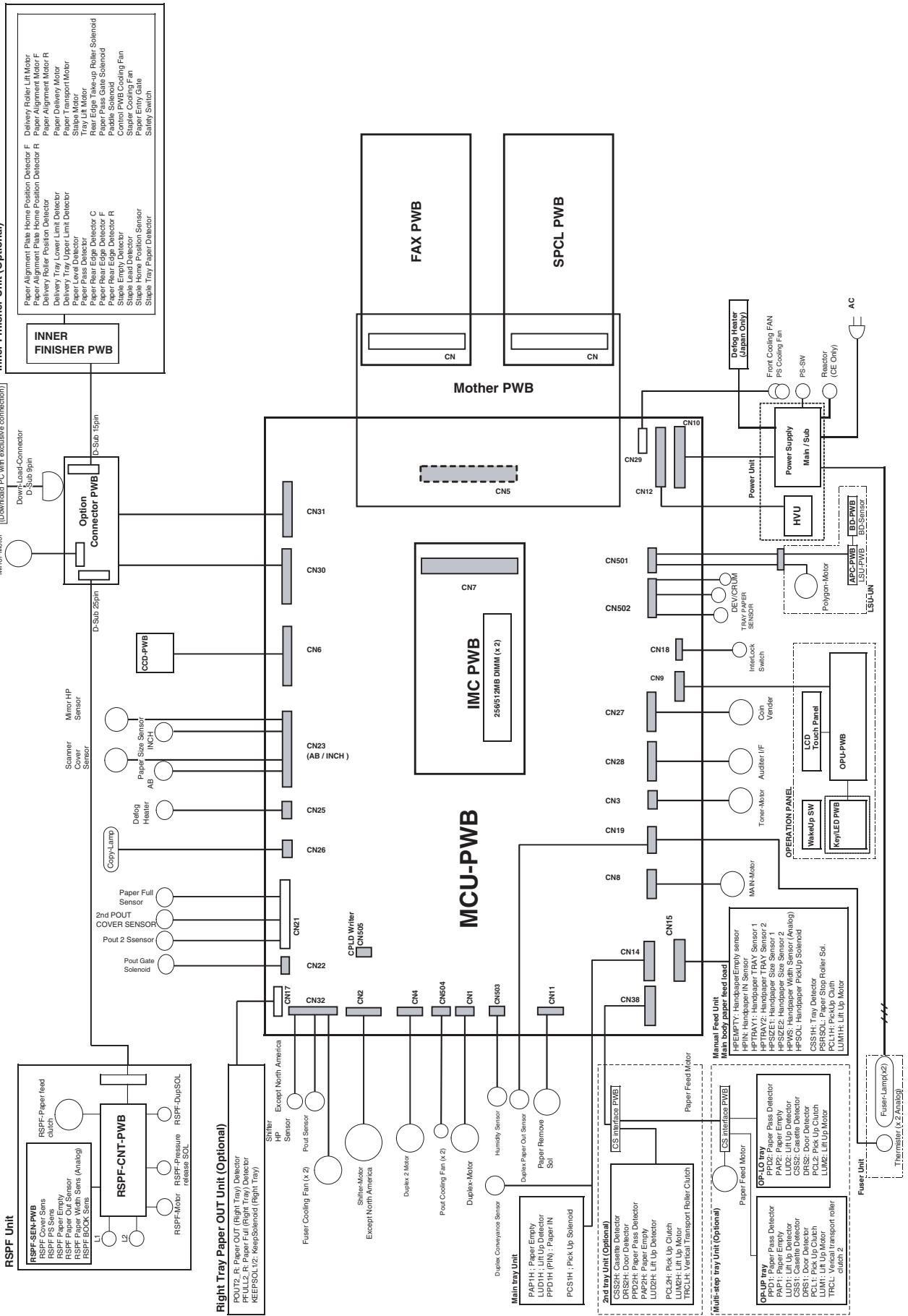
2. Schéma de câblage réel
A. MCU - Unité de panneau, section du capteur de plaque optique
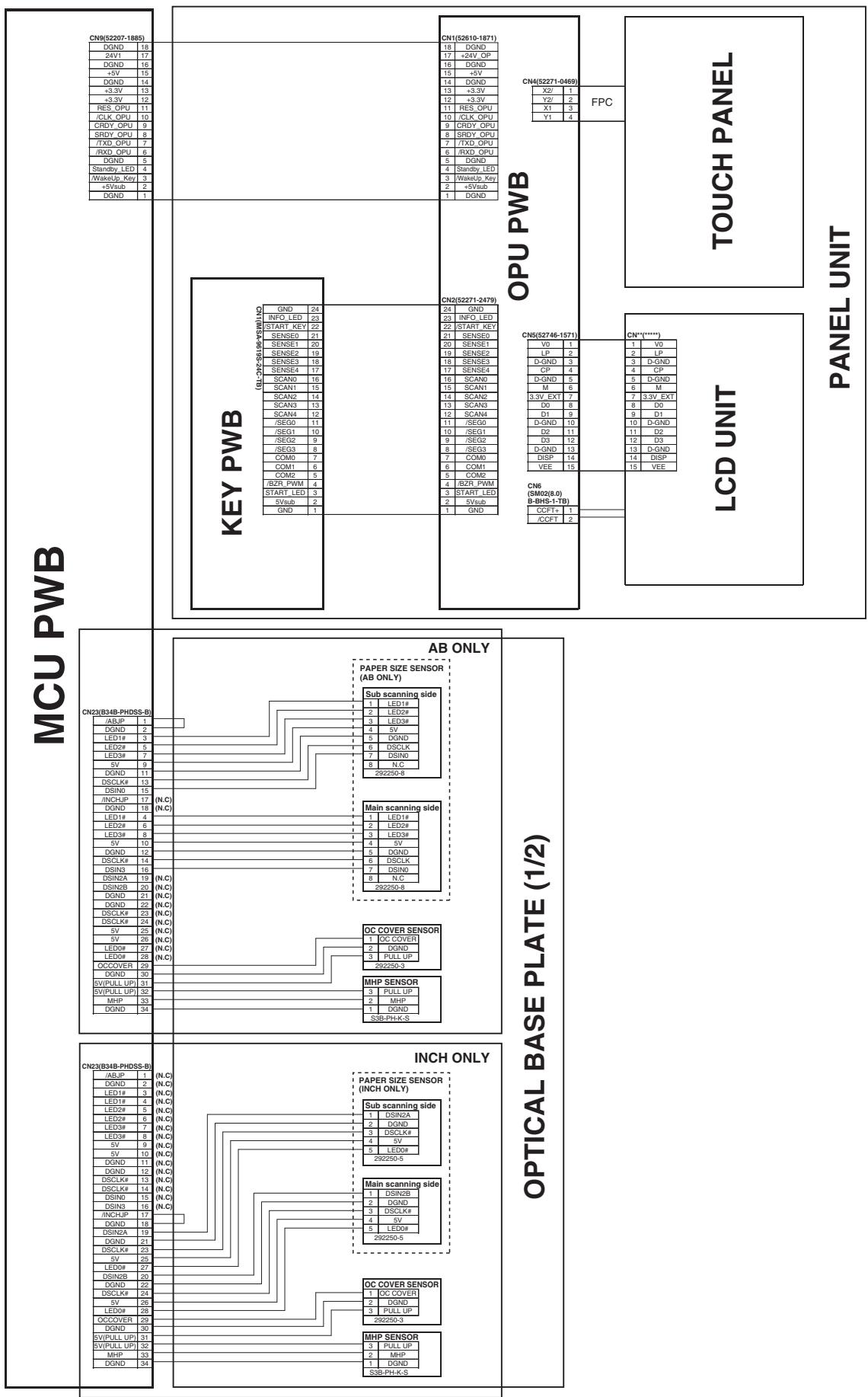
B. MCU - Plaque optique 2, carte d'interface OP, unité de sortie papier 1, unité de sortie papier 2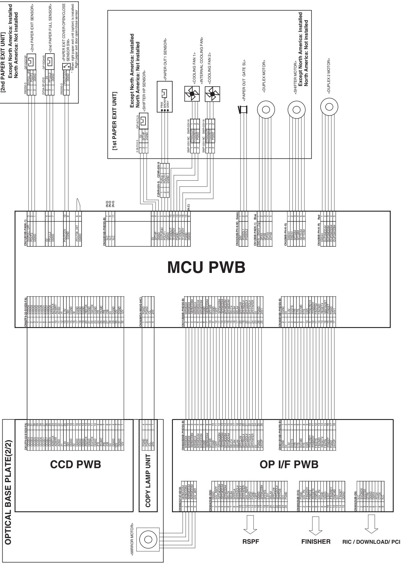
C. Alimentation manuelle, section de l'unité de bac 1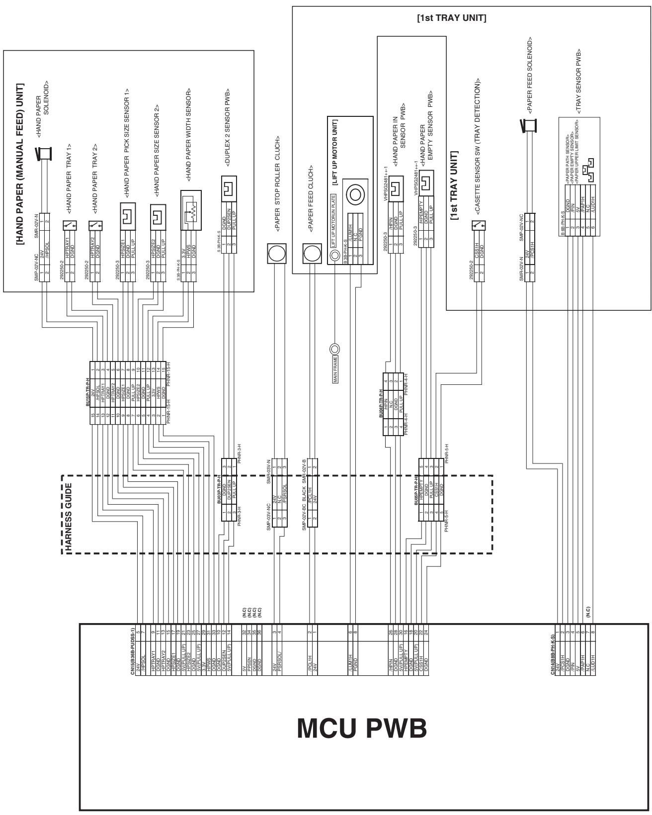
D. Section du deuxième plateau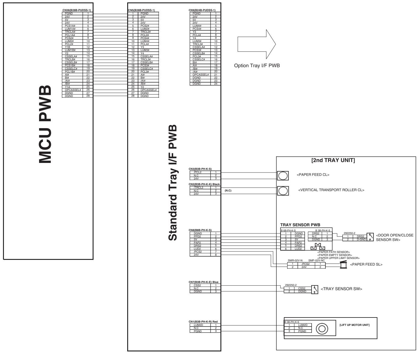
E. Section de l'unité de fusion et de l'alimentation électrique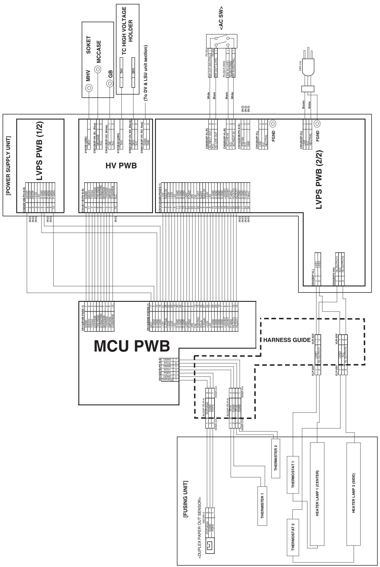
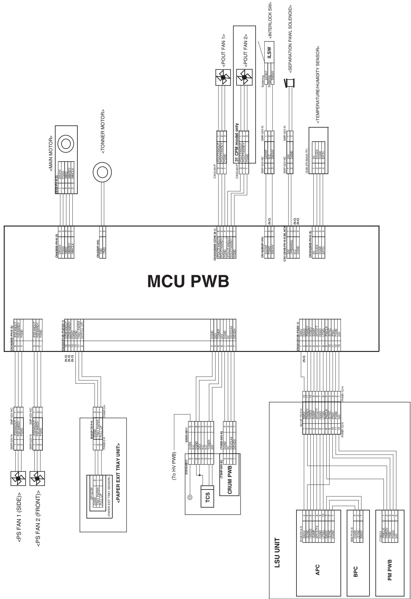
Carte SPCL
Connecteur carte à carte
Carte mère
Connecteur carte à carte
Carte FAX
- Liste des signaux
| Signal name | Name | Function/Operation | Connector level | Connector No. | Pin No. | PWB name | NOTE | |
| "L" | "H" | |||||||
| CL | Copy lamp | Controls ON/OFF of the copy lamp. | ON | OFF | CN26 | 3 | MCU | |
| CLH | RSPF clutch | Controls ON/OFF of the RSPF paper feed roller. | ON | OFF | CN5 | 13 | RSPF interface | |
| COVER | RSPF cover open/close detection | Detects open/close of the RSPF cover. | OPEN | CLOSE | CN5 | 2 | RSPF interface | |
| CSS1 | Tray 1 installation detection | Detects installation of tray 1. | NO | YES | CN15 | 22 | MCU | |
| CSS2 | Tray 2 installation detection | Detects installation of tray 2. | NO | YES | CN7 | 1 | Standard tray I/F | |
| CSS3 | Tray 3 installation detection | Detects installation of tray 3. | NO | YES | CN7 | 1 | Option tray I/F | |
| CSS4 | Tray 4 installation detection | Detects installation of tray 4. | NO | YES | CN4 | 8 | Option tray I/F | |
| DPX | Duplex motor | Controls the duplex motor. | - | - | CN1 | 2,3,4,5 | MCU | |
| DRS2 | Door open/close detection (Tray 2) | Detects door open/close. | OPEN | CLOSE | CN8 | 5 | Standard tray I/F | |
| DRS3 | Door open/close detection (Tray 3) | Detects door open/close. | OPEN | CLOSE | CN8 | 5 | Option tray I/F | |
| DRS4 | Door open/close detection (Tray 4) | Detects door open/close. | OPEN | CLOSE | CN4 | 5 | Option tray I/F | |
| DUP2SEN | DUP2 paper delivery sensor | Detects paper delivery in the reverse path. | YES | NO | CN15 | 12 | MCU | |
| EHUD | Humidity sensor | Senses the humidity. | - | - | CN503 | 2 | MCU | Analog detection |
| ERTH | Temperature sensor | Senses the temperature. | - | - | CN503 | 4 | MCU | Analog detection |
| GSOL | Gate solenoid | Reverses the paper exit gate in ON operation. | ON | OFF | CN4 | 2 | RSPF interface | |
| HLOUT1 | Heater lamp main | Turns ON/OFF the heater lamp main. | OFF | ON | CN10 | 10 | MCU | |
| HLOUT2 | Heater lamp sub | Turns ON/OFF the heater lamp sub. | OFF | ON | CN10 | 12 | MCU | |
| HPEMPTY | Manual feed paper presence detection | Detects presence of paper for manual paper feed. | YES | NO | CN15 | 16 | MCU | |
| HPIN | Manual feed paper entry detection | Detects paper entry for manual feed. | NO | YES | CN15 | 26 | MCU | |
| HPSIZE1 | Manual feed paper length detection | Detects the length of manual feed paper. | NO | YES | CN15 | 17 | MCU | |
| HPSIZE2 | Manual feed paper size detection (Longitudinal direction) | Detects the size of manual feed paper. (longitudinal direction) | NO | YES | CN15 | 23 | MCU | |
| HPSOL | Manual paper feed solenoid | Controls the manual paper feed solenoid. | ON | OFF | CN15 | 7 | MCU | |
| HPTRAY1 | Manual paper feed tray length detection | Detects the length of manual feed tray paper. | LONG | SHORT | CN15 | 9 | MCU | |
| HPTRAY2 | Manual paper feed tray length detection | Detects the length of manual feed tray paper. | SHORT | LONG | CN15 | 13 | MCU | |
| HPWS | Manual feed paper width detection | Detects the width of manual feed paper. | - | - | CN15 | 31 | MCU | |
| KEEPPSOL | Right paper exit gate solenoid | Drives the right paper exit gate solenoid. | ON | OFF | CN17 | 8,9 | MCU | |
| LUD1H | Lift-up motor upper limit detection | Detects the upper limit of the lift-up motor. | Not detected | Detected | CN14 | 8 | MCU | |
| LUD2 | Lift-up motor upper limit detection (Tray 2) | Detects the upper limit of the lift-up motor. | Not detected | Detected | CN8 | 6 | Standard tray I/F | |
| LUD3 | Lift-up motor upper limit detection (Tray 3) | Detects the upper limit of the lift-up motor. | Not detected | Detected | CN8 | 6 | Option tray I/F | |
| LUD4 | Lift-up motor upper limit detection (Tray 4) | Detects the upper limit of the lift-up motor. | Not detected | Detected | CN4 | 6 | Option tray I/F | |
| LUM1H | Lift-up motor | Drives the lift plate of the paper tray. | OFF | ON | CN15 | 6 | MCU | |
| LUM2D | Lift-up motor | Drives the lift plate of the paper tray. | OFF | ON | CN1 | 1 | Standard tray I/F | |
| LUM3D | Lift-up motor | Drives the lift plate of the paper tray. | OFF | ON | CN1 | 1 | Option tray I/F | |
| LUM4D | Lift-up motor | Drives the lift plate of the paper tray. | OFF | ON | CN4 | 14 | Option tray I/F | |
| MHP | Mirror home position sensor | Corrects the initial position of the scanner. | Other than home position. | Home position | CN23 | 33 | MCU | |
| MIRMOD | Mirror motor | Controls the mirror operation. | - | - | CN906 | 1,2,3,4 | OP I/F PWB | |
| MMD | Main motor | Controls the main motor. | ON | OFF | IC215 | 3 | MCU | |
| MMRDY | Main motor lock | Detects lock of the main motor. | Rotation | Lock | IC215 | 2 | MCU | |
| OCCOVER | OC cover open/close detection | Detects open/close of the OC cover. | OPEN | CLOSE | CN23 | 29 | MCU | |
| OZNFANOUT | Ozone fan | Controls the ozone fan. | OFF | ON | CN502 | 10 | MCU | |
| PAP1H | Paper pass sensor (Tray 1) | Detects paper pass. | YES | NO | CN14 | 6 | MCU | |
| PAP2 | Paper pass sensor (Tray 2) | Detects paper pass. | YES | NO | CN8 | 4 | Standard tray I/F | |
| PAP3 | Paper pass sensor (Tray 3) | Detects paper pass. | YES | NO | CN8 | 4 | Option tray I/F | |
| PAP4 | Paper pass sensor (Tray 4) | Detects paper pass. | YES | NO | CN4 | 4 | Option tray I/F | |
| PAPER | Paper entry sensor | Detects paper entry. | YES | NO | CN5 | 18 | SPF interface | |
| PCL1H | Paper feed clutch (Tray 1) | Controls ON/OFF of the paper feed roller. | ON | OFF | CN15 | 2 | MCU | |
| PCL2 | Paper feed clutch (Tray 2) | Controls ON/OFF of the paper feed roller. | ON | OFF | CN3 | 1 | Standard tray I/F | |
| PCL3 | Paper feed clutch (Tray 3) | Controls ON/OFF of the paper feed roller. | ON | OFF | CN3 | 1 | Option tray I/F | |
| PCL4 | Paper feed clutch (Tray 4) | Controls ON/OFF of the paper feed roller. | ON | OFF | CN4 | 10 | Option tray I/F | |
| PCS1H | Paper feed solenoid (Tray 1) | Controls ON/OFF of the paper feed roller. | ON | OFF | CN14 | 2 | MCU | |
| PCS2 | Paper feed solenoid (Tray 2) | Controls ON/OFF of the paper feed roller. | ON | OFF | CN8 | 7 | Standard tray I/F | |
| PCS3 | Paper feed solenoid (Tray 3) | Controls ON/OFF of the paper feed roller. | ON | OFF | CN8 | 7 | Option tray I/F | |
| PCS4 | Paper feed solenoid (Tray 4) | Controls ON/OFF of the paper feed roller. | ON | OFF | CN4 | 12 | Option tray I/F | |
| PDPX | Duplex sensor | Detects paper presence for duplex. | YES | NO | CN19 | 3 | MCU | |
| PFULL2 | No. 2 paper exit full sensor | Detects paper full in the No. 2 paper exit unit. | YES | NO | CN21 | 5 | MCU | |
| PFULL2_R | Right paper exit full sensor | Detects paper full in the right paper exit unit. | YES | NO | CN17 | 5 | MCU | |
| PGSOL | Paper exit gate solenoid | Controls the paper exit gate. | ON | OFF | CN22 | 2,3 | MCU | |
| PIN | Paper entry sensor | Detects paper entry. | YES | NO | CN14 | 4 | MCU | |
| POUT1 | No. 1 paper exit sensor | Detects paper exit of the No. 1 paper exit unit. | NO | YES | CN32 | 6 | MCU | |
| POUT2 | No. 2 paper exit sensor | Detects paper exit of the No. 2 paper exit unit. | YES | NO | CN21 | 2 | MCU | |
| POUT2_R | Right paper exit sensor | Detects paper exit of the right paper exit unit. | YES | NO | CN17 | 2 | MCU | |
| POUTCOV | Paper exit cover open/close detection | Detects open/close of the paper exit cover. | OPEN | CLOSE | CN21 | 10 | MCU | |
| POUTFANOUT | Paper exit cooling fan | Cools the fusing unit. | OFF | ON | CN504 | 3,6 | MCU | |
| POUTFANRDY | Paper exit cooling fan lock detection | Detects lock of the paper exit cooling fan. | Rotation | Lock | CN504 | 2,5 | MCU | |
| PPD2 | Paper pass sensor (Tray 2) | Detects paper pass. | YES | NO | CN8 | 2 | Standard tray I/F | |
| PPD3 | Paper pass sensor (Tray 3) | Detects paper pass. | YES | NO | CN8 | 2 | Option tray I/F | |
| PPD4 | Paper pass sensor (Tray 4) | Detects paper pass. | YES | NO | CN4 | 2 | Option tray I/F | |
| PREMSOL | Paper separation solenoid | Controls the paper separation solenoid. | ON | OFF | CN11 | 2 | MCU | |
| PSFANOUT | PS fan | Drives the PS fan. | OFF | ON | CN29 | 3,6 | MCU | |
| PSFANRDY | PS fan lock detection | Detects lock of the PS fan. | Rotation | Lock | CN29 | 2,5 | MCU | |
| PSOL | PS solenoid | Controls ON/OFF of the PS roller. | ON | OFF | CN5 | 11 | SPF interface | |
| PSRSOL | Resist roller solenoid | Controls the resist roller. | ON | OFF | CN15 | 4 | MCU | |
| RSOL | Reverse solenoid | Reverses the paper exit gate in ON operation. | ON | OFF | CN5 | 15 | SPF interface PWB | |
| RTH1 | Thermister 1 | Detects the fusing temperature. | - | - | CN19 | 4 | MCU | |
| RTH2 | Thermister 2 | Detects the fusing temperature. | - | - | CN19 | 6 | MCU | |
| SFTD | Shifter motor | Offsets paper. | - | - | CN2 | 3,4,5,6 | MCU | |
| SFTHP | Shifter home position sensor | Detects the home position of the shifter. | Other than home position. | Home position | CN32 | 4 | MCU | |
| SPFOPEN | SPF cover open/close sensor | Detects open/close of the SPF cover. | OPEN | CLOSE | CN5 | 24 | SPF interface | |
| SPFOUT | SPF paper exit sensor | Detects paper exit of the SPF. | YES | NO | CN3 | 1 | SPF interface | |
| SPFWS | SPF document width detection | Detects SFP documents. | - | - | CN2 | 9 | SPF interface | Analog detection |
| TFANOUT | Fusing fan | Drives the fusing fan. | OFF | ON | CN32 | 10,12 | MCU | |
| TFANRDY | Fusing fan lock detection | Detects lock of the fusing fan. | Rotation | Lock | CN32 | 14,16 | MCU | |
| TMD | Toner motor | Controls the toner motor. | - | - | CN3 | 1,2 | MCU | |
| TONER | Toner sensor | Detects the toner density. | - | - | CN502 | 6 | MCU | Analog detection |
| TRCL2 | Vertical transport clutch | Controls ON/OFF of the vertical transport roller. | ON | OFF | CN2 | 1 | Standard tray I/F | |
| TRCL3 | Vertical transport clutch | Controls ON/OFF of the vertical transport clutch. | ON | OFF | CN2 | 1 | Option tray I/F | |
| W0 | Paper empty sensor | Detects paper empty. | YES | NO | CN5 | 1 | SPF interface | |
SOUDURE SANS PLOMB
Les cartes de ce modèle utilisent une soudure sans plomb. Les marques "LF" indiquées sur les cartes et dans le manuel de service signifient "sans plomb". La lettre qui suit la marque LF indique le type de soudure sans plomb.
Exemple :
| Solder composition | Solder composition code |
| Sn-Ag-Cu | a |
| Sn-Ag-Bi | b |
| Sn-Ag-Bi-Cu | |
| Sn-Zn-Bi | z |
| Sn-In-Ag-Bi | i |
| Sn-Cu-Ni | n |
| Sn-Ag-Sb | s |
| Bi-Sn-Ag-P | p |
| Bi-Sn-Ag |
(1) REMARQUE CONCERNANT L'UTILISATION DU FIL DE SOUDURE SANS PLOMB
Lors de la réparation d'une carte avec soudure sans plomb, utilisez du fil de soudure sans plomb.
N'utilisez jamais de fil de soudure au plomb conventionnel, cela pourrait provoquer une panne ou un accident.
Étant donné que le point de fusion du fil de soudure sans plomb est d'environ 40 °C plus élevé que celui du fil de soudure conventionnel au plomb, l'utilisation d'un fer à souder exclusif est recommandée.
(2) NOTE POUR LES TRAVAUX DE SOUDURE
Étant donné que le point de fusion de la soudure sans plomb est d'environ 220 °C, soit environ 40 °C de plus que celui de la soudure conventionnelle au plomb, et que sa capacité de soudage est inférieure à celle de la soudure conventionnelle, il est fréquent de maintenir le fer à souder en contact avec la carte de circuit imprimé (PWB) plus longtemps. Cela peut provoquer le décollement des pastilles ou dépasser la température de résistance thermique des composants. Prenez soin de retirer le fer à souder de la PWB dès que la soudure est terminée.
La soudure sans plomb contenant une plus grande quantité d'étain, la pointe du fer peut se corroder facilement. Allumez et éteignez fréquemment le fer à souder.
Si de la soudure d'un autre type reste sur la pointe du fer, elle fondra avec la soudure sans plomb. Pour éviter cela, nettoyez la pointe du fer après chaque travail de soudure.
Si la pointe du fer devient noire pendant le soudage, nettoyez-la et limez-la avec de la laine d'acier ou une lime fine.
Système multifonction numérique
Système multifonction numérique
MX-M260/N/FG/FP
MX-M310/N/FG/FP
AR-5726/5731
MX-VR10
(Sauf Amérique du Nord, Japon, Argentine)
MX-RP10
MX-RP10
(Amérique du Nord, Japon,
Argentine est standard)
MODÈLE MX-TR11
(Le Japon est standard)
Les prix indiqués dans ce guide des pièces sont hors taxes.
TABLE DES MATIÈRES
1 Extérieurs 1 (Exteriors 1) 2 Extérieurs 2 (Exteriors 2) 3 Unité du panneau de commande (Operation panel unit) 4 Châssis (Frame section) 5 Unité de lampe (Lamp unit) 6 Optique 1 (Optical frame 1) 7 Optique 2 (Optical frame 2) 8 Cadre intermédiaire (Middle frame section) 9 Unité cassette 550 (550 cassette unit) 10 Section d'alimentation papier (Paper feed section) 11 Section de transport papier (Paper transfer section) 12 Unité de porte latérale (Side door unit) 13 Bac d'alimentation manuelle multiple (Multi manual paper feed tray unit) 14 Unité d'alimentation manuelle multiple (Multi manual paper feed unit) 15 Unité DV (DV unit) 16 Unité de traitement (Process unit) 17 Fixation 1 (Fusing unit 1) 18 Fixation 2 (Fusing unit 2) 19 Unité d'entraînement (Drive unit) 20 Unité de sortie papier 1 (1st delivery paper unit 1) 21 Unité de sortie papier 2 (1st delivery paper unit 2) 22 Section des cartes de circuits imprimés (PWB section) 23 Cadre arrière (Rear frame section)
24 Deuxièmes extérieurs (2nd exteriors) 25 Deuxième cassette 550 (2nd 550 cassette unit) 26 Deuxième section d'alimentation papier (2nd paper feed section) 27 Deuxième section de transport papier (2nd paper transfer section) 28 Deuxième section d'entraînement (2nd drive section) 29 Unité de levage (Lift up unit) 30 MX-RP10 Extérieurs 1 (MX-RP10 RSPF Exteriors 1) 31 MX-RP10 Extérieurs 2 (MX-RP10 RSPF Exteriors 2) 32 MX-RP10 Section d'alimentation papier (MX-RP10 RSPF Paper feeding section) 33 MX-RP10 Section de transport 1 (MX-RP10 RSPF Transport section 1) 34 MX-RP10 Section de transport 2 (MX-RP10 RSPF Transport section 2) 35 MX-TR11 Deuxième unité de sortie papier (MX-TR11 2nd delivery paper unit) 36 MX-TR11 Unité de séparation des travaux (MX-TR11 Job-separator unit) 37 Matériaux d'emballage et accessoires (Packing material & accessories) 38 MX-VR10 Matériaux d'emballage et accessoires (MX-VR10 Packing material & accessories) 39 MX-RP10 Matériaux d'emballage et accessoires (MX-RP10 Packing material & accessories) 40 MX-TR11 Matériaux d'emballage et accessoires (MX-TR11 Packing material & accessories)
<Remarques sur l'utilisation du guide de révision>
· La compatibilité des pièces est indiquée dans le tableau ci-dessous, exprimée par les numéros 1 à 6.
<Compatibilité>
| 1 | 新・旧の互換性有り。 |
| 2 | 新の代わりに旧は使用可。 旧の代わりに新は使用不可。 |
| 3 | 新の代わりに旧は使用不可。 旧の代わりに新は使用可。 |
| 4 | 新・旧の互換性無。 |
| 5 | 旧 (a, b, c...) 彪うし一对、又は 新 (a, b, c...) 彪うし一对て、互換性有。 |
| 6 | その他 |
· Les modifications telles que l'ajout, le changement, la suppression ou la variation de quantité des pièces sont indiquées dans le tableau ci-dessous par des marques.
<Catégorie de modification>
| 新規追加 | N |
| 変更 | ◎ |
| 廢止 | × |
| 員数増・その他 | ☆ |
| 員数減 | ★ |
| ハーヒさ修正 | C |
· Le moment du changement est indiqué par R/C.
<Moment du changement>
| R/C | ランニングチング |
- L'interchangeabilité des pièces est exprimée par les numéros 1 à 6, comme indiqué dans le tableau ci-dessous.
| 1 | Interchangeable. |
| 2 | Current type can be used in place of new type. New type cannot be used in place of current type. |
| 3 | Current type cannot be used in place of new type. New type can be used in place of current type. |
| 4 | Not interchangeable. |
| 5 | Interchangeable if replaced with same types of related parts in use. |
| 6 | Others. |
- Les ajouts et modifications, les changements, les suppressions et les changements de quantité sont exprimés par les marques indiquées dans le tableau ci-dessous.
| New & Addition | N |
| Change | ○ |
| Abolition | × |
| Q'quantity (increase) /Others | ☆ |
| Q'quantity (decrease) | ★ |
| Correction | C |
- Le changement en cours de validité est exprimé par R/C.
| R / C | Running Change |
Classement des pièces de rechange
Ce document a pour but d'aider à la gestion appropriée des stocks de pièces de rechange sur le marché.
Rang A : pièces d'entretien, pièces consommables non incluses dans les pièces d'entretien mais étroitement liées à celles-ci. Rang B : pièces de performance/fonction (capteurs, embrayages, autres pièces électriques), pièces consommables. Rang E : pièces d'unité, y compris les cartes de circuits imprimés. Rang D : pièces de préparation (garnitures extérieures, emballages, pièces emballées ensemble). Rang C : pièces autres que celles ci-dessus (à l'exclusion des sous-composants des cartes de circuits imprimés).
DÉFINITION
Rang A : pièces d'entretien et pièces consommables non incluses dans les pièces d'entretien mais étroitement liées à celles-ci. Rang B : pièces de performance/fonction (capteurs, embrayages, autres pièces électriques), pièces consommables. Rang E : pièces d'unité, y compris les cartes de circuits imprimés. Rang D : pièces de préparation (garnitures extérieures, emballages, pièces emballées ensemble). Rang C : pièces autres que celles ci-dessus (à l'exclusion des sous-composants des cartes de circuits imprimés).
Pour les pièces nécessaires à la sécurité et à la fiabilité, utilisez toujours des pièces d'origine.
Les pièces marquées d'un "▲" sont importantes pour la sécurité. Lors du remplacement, utilisez les pièces spécifiées nécessaires à la sécurité et au maintien des performances.
Les pièces marquées d'un "▲" sont indispensables pour la sécurité, l'entretien et le fonctionnement de la machine ; elles doivent être remplacées par les pièces spécifiques à la spécification du produit.
○ En plus de ce guide des pièces, veuillez vous référer au manuel d'entretien (y compris le schéma de circuit) de ce modèle. ○ Veuillez utiliser le code à 13 chiffres indiqué dans le coin supérieur droit de la page de garde du document lors de la passation de commande. Pour les États-Unis uniquement : utilisez les codes de commande fournis dans la documentation publicitaire. Ne commandez pas auprès du service des pièces détachées.
◁ : Nécessité de remplacement périodique : Pièces d'entretien pour lesquelles un remplacement périodique est nécessaire.
1 Extérieurs 1
| NO. | PARTS CODE | Inter-changec | PRICE RANK | NEWMARK | PARTRANK | DESCRIPTION | TR No. | Effective time | |
| Ex. | Ja. | ||||||||
| 1 | GCAB-0 081QST1 | AL | EB | D | Optical left cabinet | 光学左拉比° | |||
| 2 | GCAB-0 080QST1 | AM | EG | D | Optical right cabinet | 光学右拉比° | |||
| 3 | CFiX-0 013QS11 | AM | EG | D | Glass fixing plate (Except Japan) | 夫拉押元 | |||
| CFiX-0 013QS12 | AL | EB | D | Glass fixing plate (Japan) | 夫拉押元 | ||||
| 4 | PSHEZ0220QSZ1 | AK | DX | C | Shading sheet | 江一丁氏格卡卜 | |||
| 5 | LX-BZ0 082QSPZ | AA | DD | C | Screw(3×8) | 比x | |||
| 6 | GCAB-0 084QST1 | AS | EQ | D | Rear cabinet upper | 後拉比°上 | |||
| 7 | CGiDM0116QS05 | AK | DX | C | OR guide unit (Except Japan) | OR夫拉卡卜 | |||
| CGiDM0116QS04 | AH | DX | C | OR guide unit (Japan) | OR夫拉卡卜 | ||||
| 8 | LFiX-0 011QSAC | AK | DX | B | OC fixing glass (Except North America,Japan,Argentina) | OC夫拉押元 | |||
| 11 | PGLSP0003QSZZ | BA | FX | B | Table glass | テ-フクマ夫 | |||
| 17 | LFiX-0 012QSAC | AH | DX | D | SPF fixing glass [MX-RP10,North America,Japan,Argentina] | SPF夫拉押元 | |||
| 18 | PSHEZ0221QSZZ | AC | DJ | C | White revise sheet LPD [MX-RP10,North America,Japan,Argentina] | 白補正トLPD | |||
| 19 | PGLSP0004QSZZ | AX | FG | B | SPF slit glass [MX-RP10,North America,Japan,Argentina] | SPF リラト夫 | |||
| 20 | PSHEZ0207QSZZ | AC | DJ | C | SPF glass sheet F [MX-RP10,North America,Japan,Argentina] | SPF夫拉トF | |||
| 21 | PSHEZ0222QSZZ | AC | DJ | C | Glass fixing sheet [MX-RP10,North America,Japan,Argentina] | 夫拉固定ト | |||
| 22 | PCUSS0011QSZZ | AB | DJ | C | Glass cushion [MX-RP10,North America,Japan,Argentina] | 夫拉クマ夫 | |||
| 23 | PSHEZ0208QSZZ | AC | DJ | C | Glass sheet R [MX-RP10,North America,Japan,Argentina] | 夫拉トR | |||
| 24 | PCUSS0027QSZZ | AA | DJ | C | Glass cushion C [MX-RP10,North America,Japan,Argentina] | 夫拉クマ夫C | |||
| 25 | CSPSHEZ0088QSZ2 | - | AD | DJ | C | Table glass sheet [Missing parts code] | [MTM] 変山ト | ||
| 26 | PMLT-0 093QSZZ | AB | DJ | C | Rear cabinet upper cushion | 後半比°上もト | |||
| 27 | PSHEZ0474QSZZ | AD | DJ | C | Glass fixing sheet [MX-RP10,North America,Japan,Argentina] | 夫拉固定ト | |||
| 501 | NCFiX-0 012RS54 | - | AU | EZ | E | SPF Glass fixing unit [MX-RP10,North America,Japan,Argentina] | SPF夫拉押元 | ||
1 Extérieurs 1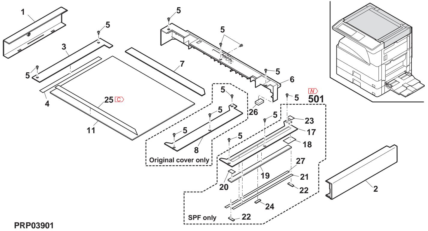
2 外装部 2 (Extérieurs 2)
| NO. | PARTS CODE | Inter-chang | PRICE RANK | NEW MARK | PART MARK | DESCRIPTION | TR No. | Effective time | ||
| Ex. | Ja. | |||||||||
| 1 | GCAB-0042QSTF | AP | EQ | D | Rear cabinet left (Except Japan) 後柱比左 | |||||
| GCAB-0042QSTG | AP | EQ | D | Rear cabinet left (Japan) 後柱比左 | ||||||
| 3 | XHBS730P08000 | AB | DD | C | Screw(3×8) | |||||
| 4 | GCAB-0145QSZZ | AU | EZ | C | Delivery tray cabinet rear | |||||
| 5 | GCÖV-0056QST1 | AG | DS | D | Rear cabinet maintenance cover 後柱比' トクスカーナー | |||||
| 6 | GCAB-0043QSTC | AM | EG | D | Rear cabinet lower (100V Series) 後柱比下 | |||||
| GCAB-0152QSZZ | AM | EG | D | Rear cabinet lower (200V Series) 後柱比下 | ||||||
| 7 | XEBS740P10000 | AA | DD | C | Screw(4×10) | |||||
| 8 | GCAB-0085QST5 | AY | FQ | D | Rear cabinet right (Except Japan) 後柱比右 | |||||
| GCAB-0085QST6 | 1 | AY | FG | D | Rear cabinet right (Except Japan) 後柱比右 | 09/10 R/C | ||||
| GCAB-0085QST6 | AY | FG | D | Rear cabinet right (Japan) 後柱比右 | ||||||
| 9 | GCÖV-0034QSTC | AK | DX | C | Rear cabinet memory cover 後柱比' リル加一 | |||||
| 10 | PCOVP0130QSZZ | AM | EG | D | Delivery dummy cover (Except Japan) 掺絵さ広加一 | |||||
| 11 | MSPRD0189QSZZ | AB | DJ | C | Right cabinet spring 右柱比' ラル加一 | |||||
| 12 | MLEVOP0069QSTZ | - | AD | DJ | C | Right cabinet lever [Missing parts code] 右柱比' ' | ||||
| 13 | GDOR-0003QST7 | - | AP | EQ | D | Right cabinet door [Missing parts code] 右柱比' ' | ||||
| 14 | NROLP1060FCZZ | AF | DS | C | U-turn roller U形の右 | |||||
| 15 | MSPRT0229GCAZ | AC | DJ | C | FU spring R FU柱' 'R' | |||||
| 16 | GCAB-0039QSTC | - | AS | EZ | D | Right cabinet [Missing parts code] 右柱比' | ||||
| 17 | GCÖV-0043QST2 | AX | FG | D | Option PWB cover 空地基板加一 | |||||
| 18 | PF I Z0016QSZZ | AS | EQ | B | Ozone filter 抽空滤芯 | |||||
| 19 | GCÖV-0086QSZZ | AN | EG | C | Delivery cover 排紙加一 | |||||
| 21 | GCAB-0149QSZZ | AV | FG | C | Left cabinet (Japan) 左柱比' | |||||
| GCAB-0149QSZ1 | - | AV | FG | C | Left cabinet [Missing parts code](Except Japan) 左柱比' | |||||
| 23 | GCAB-0142QSZZ | AL | EB | C | Front cabinet right 前柱比右 | |||||
| 24 | GCAB-0148QSZZ | AW | FG | C | Right cabinet front 右柱比前 | |||||
| GCAB-0148QSZ1 | 3 | AW | FG | C | Right cabinet front [Improve reliability] 右柱比前 | |||||
| 25 | LBNDZ0007QSZZ | AC | DJ | C | Front cabinet band A2R 前柱比' 'A2R' | |||||
| 26 | GCAB-0141QSZZ | AT | EZ | C | Front cabinet 前柱比' | |||||
| 27 | TLABZ5148FCZZ | AC | DJ | D | Energy star label [MX-M260(Except Argentina)/M260FG/M260FP/M310(Except Argentina)/M310FG/M310FP,AR-5726/5731(East Europe)]' | |||||
| 27 | LX-BZ0082QSPZ | AA | DD | C | Screw(3×8) | |||||
| 39 | TCAUA1069FCZZ | AC | DJ | D | Service caution label (Except Japan) 水平注意表一 | |||||
| 40 | TLABZ0793QSZZ | AC | DJ | D | Class 1 label NEW (Except North America, Japan) 水平1' 'NEW | |||||
| TLABG5005FCZZ | AC | DJ | D | Class 1 label JPN (Japan) 水平1' 'JPN | ||||||
| 44 | TLABH0483QSZZ | AC | DJ | D | Warm heater label (Japan) 保温比-4' 'A4' | |||||
| 49 | MARMP0050QSZZ | AF | DS | D | Paper fixing arm 用紙押入一 | |||||
| 50 | GCOVH0024QST2 | AE | DS | D | FAX connector cover (Japan) FAX号码' - | |||||
| 52 | TLABH5200FCZZ | AB | DJ | D | Plug caution label (Japan) 'A4' 'J' | |||||
| 53 | TCAUH1071FCZZ | BC | GD | D | Service caution label PO (Germany, Switzerland, East Europe) PO | |||||
| 54 | TLABZ5048FCZZ | AB | DJ | D | WEEE mark label [Germany, Switzerland, East Europe, Europe, UK, kingdom, AR-5726/5731] WEEE ヤルフ一 | |||||
| 61 | PSHEZ0568QSZZ | AD | DJ | C | R cabinet sheet 右柱比' | |||||
| PSHEZ0568QSZZ | - | AD | DJ | C | R cabinet sheet 右柱比' | |||||
| 63 | PCOVP0142QSZZ | AE | DS | C | Fan cover 抽空比' | |||||
| 65 | GCAB-0144QSZZ | AK | DX | C | Delivery tray joint cabinet 接紙扱売連絡比' | |||||
| 66 | PCOVP0144QSZZ | AD | DJ | C | R cabinet lever cover (Except Japan) 右柱比' '加一' | |||||
| 67 | HBDGD0058FCZZ | AT | EQ | C | Front cabinet badge [MX-M Series] 前柱比' 'n' | |||||
| CBDGD0062FC35 | AH | DX | C | Model name plate [MX-M260] 模種名' 'L' | ||||||
| CBDGD0062FC34 | AH | DX | C | Model name plate [MX-M310] 模種名' 'L' | ||||||
| CBDGD0062FC39 | AG | DX | C | Model name plate [MX-M260N] 模種名' 'L' | ||||||
| CBDGD0062FC38 | AG | DX | C | Model name plate [MX-M310N] 模種名' 'L' | ||||||
| CBDGD0062FC42 | AG | DX | C | Model name plate [MX-M260FP] 模種名' 'L' | ||||||
| CBDGD0062FC40 | AG | DX | C | Model name plate [MX-M310FP] 模種名' 'L' | ||||||
| CBDGD0062FC43 | AG | DX | C | Model name plate [MX-M260FG] 模種名' 'L' | ||||||
| CBDGD0062FC41 | AG | DX | C | Model name plate [MX-M310FG] 模種名' 'L' | ||||||
| CBDGD004QS01 | AN | EQ | C | Model name plate [AR-5726] 模種名' 'L' | ||||||
| CBDGD004QS02 | AN | EQ | C | Model name plate [AR-5731] 模種名' 'L' | ||||||
| 69 | PBOX-0006QSZ1 | AE | DS | D | Delivery sensor BOX 排紙移動' 'b' | |||||
| 70 | XEBS730P10000 | AC | DD | C | Screw(3×10) 'b' | |||||
| 71 | VHPGP1S73P+-18 | AF | DS | B | Photo sensor(GP1S73P) 排紙移動' 'b' | |||||
| 72 | MLEVP0068QSTZ | AC | DJ | C | Delivery tray actuator 排紙移動' 'b' | |||||
| 73 | DHA i-0370QSPZ | AF | DS | C | Delivery paper detect sensor harness 排紙紙機検知を一トス | |||||
| 74 | GCAB-0143QSZZ | BA | FX | D | Delivery tray cabinet 排紙移動' 'b' | |||||
| 75 | PSHEZ0392QSZ1 | AB | DJ | C | Paper feed solenoid sound proof B 普通材 B | |||||
| 79 | TLABZ5059FCZZ | AB | DJ | D | BM link label [MX-M260FP/M310FP] BM リルフ一 | |||||
2 外装部 2 (Extérieurs 2)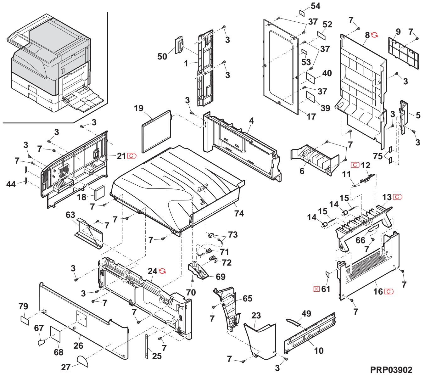
3 操作部 (Panneau de commande)
| NO. | PARTS CODE | Inter-chang | PRICE RANK | NEW MARK | PART RANK | DESCRIPTION | TR No. | Effective time | ||
| Ex. | Ja. | |||||||||
| 1 | PSHEZ 20646QSPZ | AE | DJ | C | PWB protect sheet | 基板保護ト | ||||
| 2 | XEBS 730P08000 | AC | DD | C | Screw(3×8) | t'λ | ||||
| 3 | DHA i-0503QSPZ | AE | DS | C | KEY PWB harness | KEY 基板ハス | ||||
| 4 | CPWBX 0211QSF2 | BR | LX | E | OPU PWB (North America, Philippines, Thailand, Indonesia, India, Special country, Malaysia, Singapore, Argentina) | OPU 基板 | ||||
| CPWBX 0211QSF4 | BR | LX | E | OPU PWB (Europe, U.kingdom) | OPU 基板 | |||||
| CPWBX 0211QSF5 | BR | LX | E | OPU PWB (Germany, Switzerland, East Europe) | OPU 基板 | |||||
| CPWBX 0211QSF7 | BR | LX | E | OPU PWB (Algeria, Iran, Egypt, Syria, Tunisia, Nigeria, West Africa, Morocco, Jordan, Lebanon, UAE, Yemen, Oman, Qatar, Kuwait, Bahrain, Saudi Arabia) | OPU 基板 | |||||
| CPWBX 0211QSF3 | BR | LX | E | OPU PWB (Japan) | OPU 基板 | |||||
| 5 | MSPRP 3009FCZZ | AD | DJ | C | LCD earth plate | LCD 用TA板 | ||||
| 6 | LHLDZ0119QSZZ | AK | EB | C | LCD holder B | LCD ヤフ" -B | ||||
| 7 | VVL B1HB1T03-A | BV | RB | B | LCD module | LCD ヤフ" -B | ||||
| 8 | LHLDZ0118QSZZ | AL | EB | E | LCD holder | LCD ヤフ" -B | ||||
| 9 | PSHEZ 25764FCZZ | AC | DJ | C | Touch panel sheet | 勿加" 标示" | ||||
| 10 | HPNLH0264FCZZ | BF | GN | B | Touch panel 8.1 | 勿加" 标示" | ||||
| 11 | CPNLC0072QS05 | AX | FG | C | Operation panel B EX (Except Germany, Switzerland, East Europe, Japan) | 操作" 标示" BEX | ||||
| CPNLC0072QS03 | - | AX | FG | C | Operation panel AS [Missing parts code] (Germany, Switzerland, East Europe) | 操作" 标示" AS | 1st lot | |||
| CPNLC0072QS04 | AX | FG | C | Operation panel B J | Operation B J | |||||
| 14 | PLNS -0016QSZZ | AD | DJ | B | FAX Lens | FAX ヤフ" | ||||
| 15 | CPNLC0070QS02 | AR | EQ | C | Operation panel 8.1 EX (Except Japan) | 操作" 标示" A8.1EX | ||||
| CPNLC0070QS01 | AT | EZ | C | Operation panel 8.1 J | Operation 操作" 标示" A8.1J | |||||
| 18 | JBTN -0071QSA1 | AR | EQ | C | Mode key | t'卜-ト | ||||
| 19 | CBTN -0290FC01 | AK | DX | C | Ten key | テス-ト | ||||
| 20 | CBTN -0292FC03 | AR | EQ | C | Interrupt key | 割り運動ト | ||||
| 21 | PF i LW0319FCZZ | AK | EB | C | Copy key ring | 北一卡リデ | ||||
| 22 | PLNS -0105FCZZ | AC | DJ | B | Power supply key lens | 電源扱用レフ | ||||
| 23 | CBTN -0291FC02 | AG | DX | C | CA key EX (Except Japan) | CA 才 EX | ||||
| CBTN -0291FC01 | AG | DX | C | CA key J | (CAN) CA +J | |||||
| 24 | JBTN -0284FCAZ | AR | EQ | C | Copy key | 北一卡- | ||||
| 25 | CPWBF 0234QSE2 | AX | FG | E | Key PWB (MX-M Series except Japan) | KEY 基板 | ||||
| CPWBF 0234QSE1 | AZ | FX | E | Key PWB (Japan) | KEY 基板 | |||||
| CPWBF 0234QSE3 | AY | FQ | E | Key PWB (AR-57 Series) | KEY 基板 | |||||
| 26 | LDA i U0037QSZZ | AS | EZ | C | Operation base plate A | 操作台板 A | ||||
| 27 | QCNW -0249FCPZ | AZ | FQ | C | LCD-FFC P2 | LCD-FFC P2 | ||||
| 28 | LDA i U0038QSZZ | AQ | EQ | C | Operation base plate B | 操作台板 B | ||||
| LDA i U0038QSZ1 | 1 | AQ | EQ | C | Operation base plate B | 操作台板 B | 09/08 mid | |||
| 29 | XEBS 740P10000 | AA | DD | C | Screw(4×10) | t'λ | ||||
| 30 | LPLTP 0499QSZZ | AD | DJ | C | Operation panel side plate left | 操作" 标示"板左 | ||||
| 31 | LPLTP 0498QSZZ | AE | DJ | C | Operation panel side plate right | 操作" 标示"板右 | ||||
| 32 | CPNLH 0073QS01 | AZ | FQ | C | Key sheet [English for FAX(MX-M Series)] | 卡-ト | ||||
| CPNLH 0073QS02 | AP | EQ | C | Key sheet [English no FAX(MX-M Series)] | 卡-ト | |||||
| CPNLH 0073QS03 | AP | EQ | C | Key sheet [French for FAX(MX-M Series)] | 卡-ト | |||||
| CPNLH 0073QS04 | AS | EQ | C | Key sheet [French no FAX(MX-M Series)] | 卡-ト | |||||
| CPNLH 0073QS22 | AN | EQ | C | Key sheet [English (AR-57 Series)] | 卡-ト | |||||
| CPNLH 0073QS23 | AZ | FX | C | Key sheet [French (AR-57 Series)] | 卡-ト | |||||
| 501 | CHLDZ0118RS51 | - | BX | RR | E | LCD unit [Missing parts code] LCD ヤフ" | 1st lot | |||
| Operation panel unit [MX-M Series(North America, Australia, New Zealand, Philippines, Thailand, Indonesia, India, Special country)]操作" 标示" 口 | ||||||||||
| CPNLH 0070RS53 | CC | UB | E | Operation panel unit [MX-M Series(Europe, U.kingdom)]操作" 标示" 口 | ||||||
| CPNLH 0070RS52 | CC | UB | E | Operation panel unit [MX-M260FP/M310FP]操作" 标示" 口 | ||||||
| CPNLH 0070RS54 | CC | UB | E | Operation panel unit [MX-M260FP/M310FG]操作" 标示" 口 | ||||||
| CC | UB | E | Operation panel unit [MX-M Series(North America, Australia, New Zealand, Philippines, Thailand, Indonesia, India, Special country)]操作" 标示" 口 | |||||||
| CPNLH 0070RS53 | CC | UB | E | Operation panel unit [MX-M Series(Europe, U.kingdom)]操作" 标示" 口 | ||||||
| CPNLH 0070RS52 | CC | UB | E | Operation panel unit [MX-M260FP/M310FP]操作" 标示" 非标示" 口 | ||||||
| CPNLH 0070RS54 | CC | UB | E | Operation panel unit [MX-M260FP/M310FG]操作" 标示" 口 | ||||||
3 操作部 (Panneau de commande)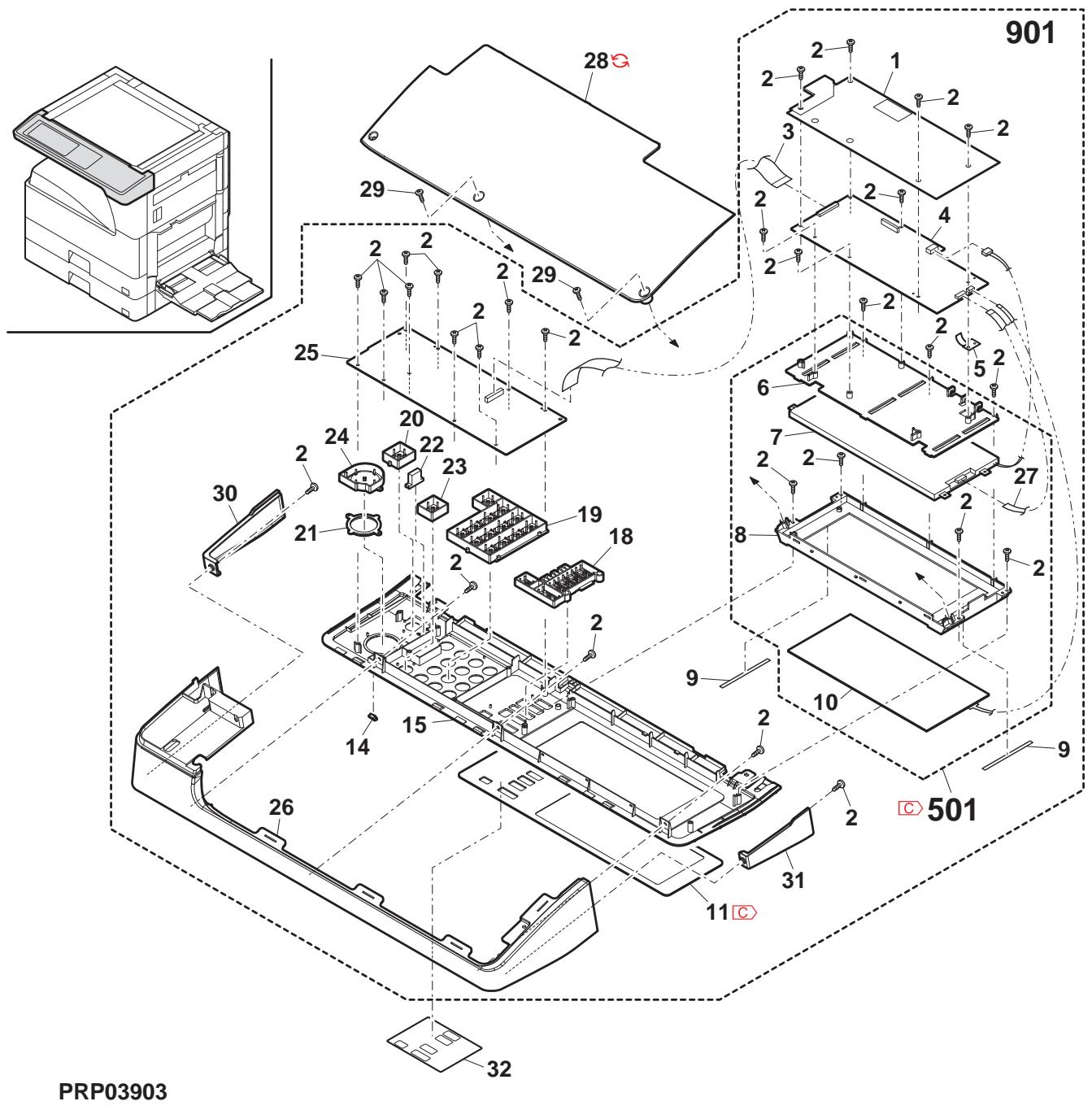
4 フレーム部 (Section du châssis)
| NO. | PARTS CODE | Inter-changese | PRICE RANK | NEW MARK | PART RANK | DESCRIPTION | TR No. | Effective time | |
| Ex. | Ja. | ||||||||
| 1 | LPLTM0163QSZZ | AK | EB | C | Left reinforce plate lower 左補強板下 | ||||
| 2 | XHBS730P08000 | AB | DD | C | Screw(3×8) ヒλ | ||||
| 3 | LPLTM0232QSZ2 | AU | EQ | C | Frame reinforce plate R ルム補強板R | ||||
| 4 | CFRM-0043QS03 | AX | FQ | D | Corner frame RL ハフリフRL | ||||
| 5 | XEBS740P10000 | AA | DD | C | Screw(3×10) ヒλ | ||||
| 6 | CPLTM0529QS01 | - | AG | DS | C | DUP drive idle plate And2 Ref [Missing parts code] DUP 驅動74" ナフレト And2 Ref | 1st lot | ||
| 7 | PSHEZ0507QSZZ | AA | DJ | C | Pulley flange sheet N フリーダフリフトN | ||||
| 9 | NPLYZ0036QSZZ | AD | DJ | C | DUP idle pulley TLPD DUP?74" ナフリフリLFWD | ||||
| 11 | LDAi-0023QSTE | BG | GT | D | Base plate 台板 | ||||
| 14 | LHLDW1757FCPZ | AC | DJ | C | Wire saddle(HL-18-0) ナフリフリル | ||||
| 15 | XHBS740P10000 | AA | DD | C | Screw(4×10) ヒλ | ||||
| 16 | LPLTM0333QSZ2 | AX | FG | C | Frame reinforce plate F ルム補強板F | ||||
| 18 | XRESP40-06000 | AA | DD | C | E type ring(E4) E ヒλ | ||||
| 19 | NBLTT0026QSZZ | AF | DS | B | DUP drive belt DUP 驅動74" ナル | ||||
| 20 | LPLTM0165QSZ3 | AS | EZ | C | Front reinforce plate 前補強板 | ||||
| 21 | PCOV0110QSZ1 | AE | DJ | D | Interlock cover 介入- DUT 加- | ||||
| 22 | LPLTM0166QSZZ | AC | DJ | C | Front support adjusting plate 前支持調整板 | ||||
| 23 | CFRM-0044QS03 | BB | FX | C | Right frame unit 右ル�-山地 | ||||
| 24 | LPLTM0251QSZ1 | AE | DS | C | PS earth plate PS?74"板 | ||||
| 25 | NSFTZ0048QSPZ | AF | DS | C | Cassette collar shaft はりト2ド触 | ||||
| 26 | NKOM-005QSZZ | AC | DJ | C | Cassette guide collar はりト2ド触 | ||||
| 27 | XBPS730P08KS0 | AB | DD | C | Screw(3×8KS) ヒλ | ||||
| 28 | XHBS730P06000 | AC | DD | C | Screw(3×6) ヒλ | ||||
| 29 | LANGF0012QSZZ | AF | DS | C | Right reinforce angle (Japan) 右補強74" ナル | ||||
| 30 | XBBS740P06000 | AA | DD | C | Screw(4×6) (Japan) ヒλ | ||||
| 40 | PSHEZ0333QSZZ | AC | DJ | C | PS front sheet PS前ト | ||||
| 41 | PSHEZ0325QSZZ | AB | DJ | C | Frame lower sheet ルム下部 | ||||
| 42 | CPLTM0342QS01 | AH | DX | C | DU motor fixing plate ASS'Y DU E-3-取付板 總品 | ||||
| 43 | NGERH0174QSZ1 | AD | DJ | C | DUP drive gear TLPD DUP 驅動74" ナル TLPD | ||||
| 44 | RMOTSO056QSP1 | - | BD | GJ | B | DUP reverse motor [Missing parts code] DUP 反転74" - | |||
| 45 | NBLTT0038QSZZ | AF | DS | B | DUP drive belt TL DUP 驅動74" ナル TL | ||||
| 46 | LPLTM0332QSZZ | AE | DJ | C | Fusing unit earth plate 定義上山地板 | ||||
| 47 | LPLTM0495QSZZ | AE | DJ | C | Power supply switch fixing plate And2 Ref 電源74" 取付板 And2 Ref | ||||
| 48 | XEBS740P12000 | AA | DD | C | Screw(4×12) ヒλ | ||||
| 55 | PMLT-0091QSZ1 | AD | DJ | C | Right frame cushion A 右ル�-山地 A | ||||
| 56 | PGSK-0044QSPZ | AH | DX | C | OP holder cushion [Except MX-M310FG] OP ヒフリ-クフ広 | ||||
| 61 | NPLYZ0015QSZZ | AC | DJ | C | Pulley(S2M20T) フリ- | ||||
| 62 | MSPRC1315FCZ1 | AD | DJ | C | Manual paper feed clutch spring A 手差74" ナフリフリス A | ||||
| 63 | NGERH0066QSZZ | AD | DJ | C | 1 way gear(17T) 1カハネ74" A | ||||
| 64 | PSHEZ0432QSZZ | AA | DJ | C | PS front sheet 2 PS前ト2 | ||||
| 65 | LBSHC0009QSPZ | AC | DJ | C | Edge bush(CE-012 L15) 1カフリフリス | ||||
| 66 | LHLDW1009ACZZ | AA | DD | C | Clamp(UAMS-05S-2) 万円74" | ||||
| 67 | PSHEZ0448QSZZ | AA | DJ | C | Optical bottom sheet And 光学底座 And | ||||
| 68 | NFANP0020QSPZ | AP | EQ | B | Fan motor ANR2 74" キフリ-ANR2 | ||||
| 69 | XBP5730P30KS0 | AC | DD | C | Screw(3×30KS) ヒλ | ||||
| 70 | CPLTM0530QS01 | - | AF | DS | C | DUP drive rotation plate And2 Ref [Missing parts code] DUP 驅動回転板 And2 Ref | 1st lot | ||
| 71 | MSPRT0147QSZZ | AC | DJ | C | Stopper arm spring ボフリ-74" ナフリフリス | ||||
| 72 | LX-BZ0852FCZZ | AC | DD | C | Step screw 段比74" | ||||
4 フレーム部 (Section du châssis)
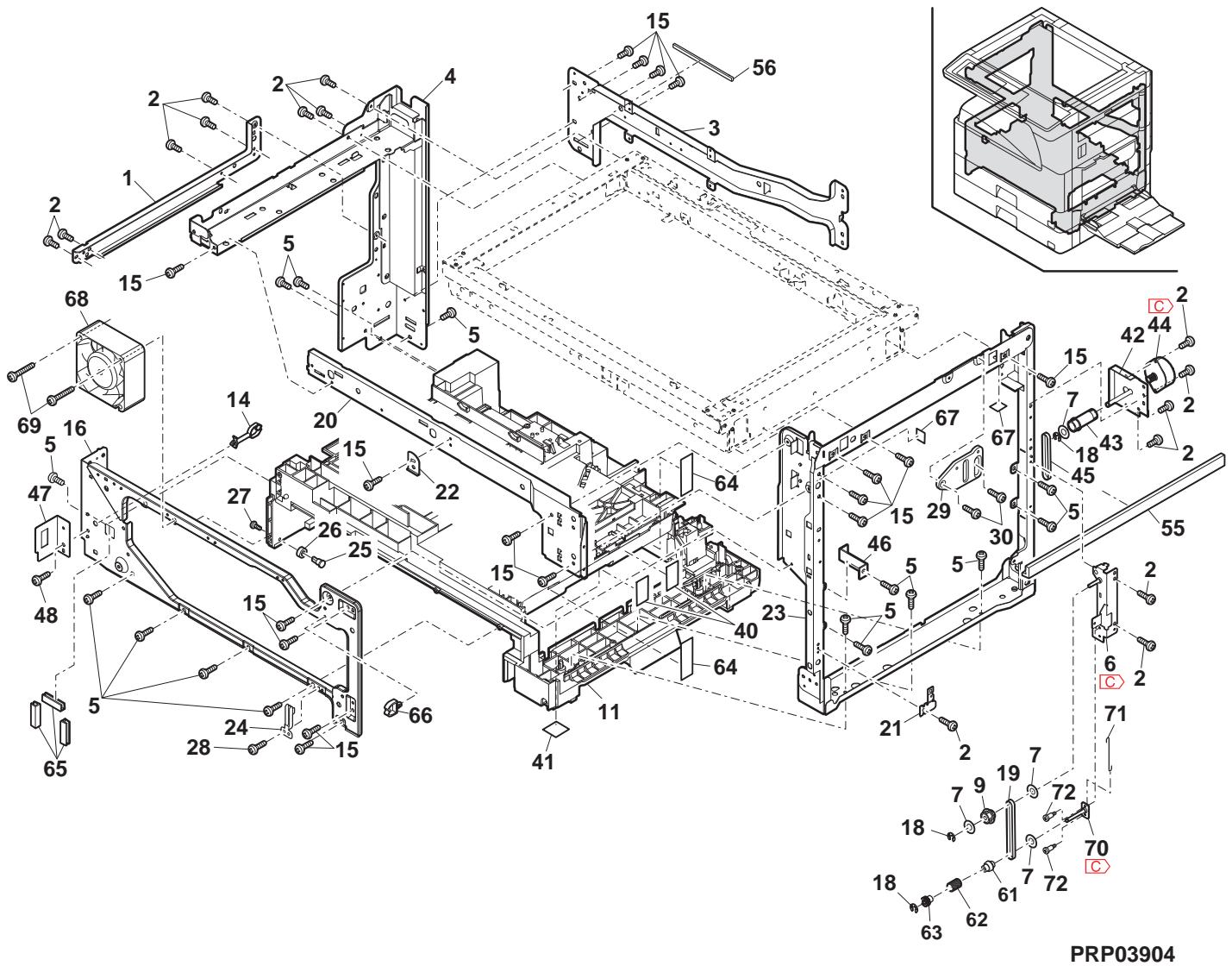
5 ランプユニット (Unité de lampe)
| NO. | PARTS CODE | Inter-charge | PRICE RANK | NEW MARK | PART RANK | DESCRIPTION | TR No. | Effective time | |
| Ex. | Ja. | ||||||||
| 1 | PREF L 0004QSZZ | AP | EQ | B | Reflector リルガーネ | ||||
| 2 | RLMPU0012QSZZ | BG | GT | B | Lamp フロー | ||||
| 3 | LHLDZ0047QSZ3 | AW | FG | C | Base ハーλ | ||||
| 4 | MSL1-0138FCZZ | AC | DJ | C | Slider ナマ材 | ||||
| 5 | PCUSU0203FCZZ | AE | DS | C | Protection cushion 防振か針線 | ||||
| 6 | MSPRP0145QSZZ | AF | DS | C | Mirror spring フロー リフロー | ||||
| 7 | PM iR-0009QSZZ | AS | EQ | B | 1st mirror 1st フロー | ||||
| 8 | DUNTK0034QSP3 | BK | HC | E | Inverter unit トナリス | ||||
| 9 | DHA i-0200QSZZ | AS | EZ | C | CL harness CL ルフロー | ||||
| 10 | LF iX-0009QSZZ | AF | DS | D | Harness fixing ルフロー | ||||
| 11 | PCUSS0033QSZZ | AC | DJ | C | Mirror cushion フロー リフロー | ||||
| 12 | XEBS830P06000 | AB | DD | C | Screw(3×6) フロー | ||||
| 14 | LPLTM4715FCZ1 | AF | DS | C | Wire fixing plate F フロー 取付板 F | ||||
| 15 | TCAUH0933FCZZ | AB | DD | D | High temperature caution label 高温注意ごし | ||||
| 16 | CXEPS830P06K00 | - | AC | DD | C | Screw(3×6K) [Missing parts code] フロー (3×6K) | 1st lot | ||
| 17 | CXEPS830P08K00 | - | AC | DD | C | Screw(3×8K) [Missing parts code] フロー (3×8K) | 1st lot | ||
| (Unit) | |||||||||
| 901 | CREFL0004QS38 | - | BR | MJ | E | Copy lamp unit [Missing parts code] フロー リフロー | 1st lot | ||
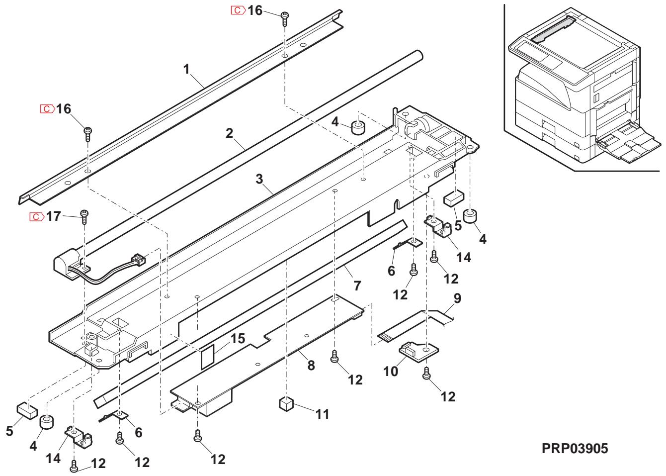
6 光学1 (Cadre optique 1)
| NO. | PARTS CODE | Inter-chang | PRICE RANK | NEW MARK | PART RANK | DESCRIPTION | TR No. | Effective time | |
| Ex. | Ja. | ||||||||
| 1 | PW i R - 0006QSPZ | AZ | FQ | C | MB wire F MB リフ - F | ||||
| 2 | CDA i U01 12QS15 | BG | GT | C | Optical base plate 光学台板 | ||||
| 3 | NPL YZ0016QSZZ | AF | DS | C | Pulley 定力 - L | ||||
| 4 | NPL YZ0006QSZ1 | AD | DJ | C | L pulley L フリ - | ||||
| 5 | XRESP40-05000 | AA | DD | C | E type ring(E4) E リフ | ||||
| 6 | PW i R - 0005QSP1 | AZ | FQ | C | MB wire R MB リフ - R | ||||
| 7 | CM i R - 0008QS36 | BB | GD | E | 2/3 mirror unit 2/3 フリーナト | ||||
| 8 | CREFL0004QS38 | - | BR | MJ | E | Copy lamp unit [Missing parts code] 北" - リフ・ルト | 1st lot | ||
| 9 | XBPS740P06K00 | AA | DD | C | Screw(4×6K) ヒλ | ||||
| 10 | LHLDZ0056QSZZ | AC | DJ | C | Wire holder ナフ・ルト - | ||||
| 11 | LX-BZ0004QSPZ | AB | DD | C | Screw ヒλ | ||||
| 12 | LRALM0007QSZ1 | AG | DS | C | MB-B rail R MB-B lever R | ||||
| 13 | LRALM0006QSZZ | AG | DS | C | MB-B rail F MB-B lever F | ||||
| 14 | XBPS730P05K00 | AA | DD | C | Screw(3×5K) ヒλ | ||||
| 15 | RMOTP0027QSZZ | BG | GT | B | Mirror motor フリーナト - | ||||
| 16 | MSPRC0040QSZZ | AB | DJ | C | MB drive spring MB 驱動効 リフ | ||||
| 17 | CPLTM0084QS02 | AK | DX | C | Mirror motor fixing plate フリーナト 取付板 | ||||
| 18 | PGUMS0002QSPZ | AL | EB | C | Protection rubber 防振圏 - | ||||
| 19 | XBPS740P16KS0 | AB | DD | C | Screw(4×16KS) ヒλ | ||||
| 20 | PGUMS0004QSZZ | AA | DJ | C | Table glass cushion フリーナト・デークIJ - | ||||
| 21 | XRESP50-06000 | AA | DD | C | E type ring(E5) E リフ - | ||||
| 22 | NBRGP0012QSZZ | AC | DJ | C | Winder bearing R 卷取り軸受 R | ||||
| 23 | NPLYZ0004QSZZ | AG | DX | C | Winder drive shaft pulley 卷取り軸受轴 フリーナト - | ||||
| 24 | NPLYZ0031QSZZ | AL | EB | C | Winder pulley 卷取りフ - | ||||
| 25 | LX-BZ0049FCPZ | AB | DD | C | Screw ヒλ | ||||
| 26 | XPSSJ30-12000 | AB | DD | C | Spring pin(φ3-12) λ' リフ・ルト - | ||||
| 27 | NSFTZ0028QSZ1 | AS | EQ | C | Winder drive shaft 卷取り軸受轴 | ||||
| 28 | LX-BZ0324FCPZ | AA | DD | C | Screw ヒλ | ||||
| 29 | NBLTT0002QSZZ | AH | DX | B | Winder drive belt 卷取り軸受轴 - 裁制 - | ||||
| 30 | NGERH0027QSZZ | AH | DX | C | Mirror motor idle gear フリーナト・デークIJ - | ||||
| 31 | LX-WZ0119FCP1 | AC | DD | C | Washer フリーナト - | ||||
| 32 | XRESP70-08000 | AA | DD | C | E type ring(E7) E リフ - | ||||
| 33 | NBRGP0011QSZZ | AC | DJ | C | Winder bearing F 卷取り軸受 F | ||||
| 34 | LX-BZ0082QSPZ | AA | DD | C | Screw(3×8) ヒλ | ||||
| 35 | PG i DM0108QST1 | AG | DX | C | Hinge guide L 業が応ド L | ||||
| 36 | XHBS730P08000 | AB | DD | C | Screw(3×8) ヒλ | ||||
| 37 | PG i DM0109QST1 | AG | DX | C | Hinge guide R フリーナト・R | ||||
| 38 | LPLTM0497QSZZ | AG | DS | C | Panel support plate LN バ補支持板 LN | ||||
| 39 | LANGF0021QSZZ | AF | DS | C | Panel reinforce angle R フリ補強効効 R | ||||
| 40 | XHBS740P10000 | AA | DD | C | Screw(4×10) ヒλ | ||||
6 光学1 (Cadre optique 1)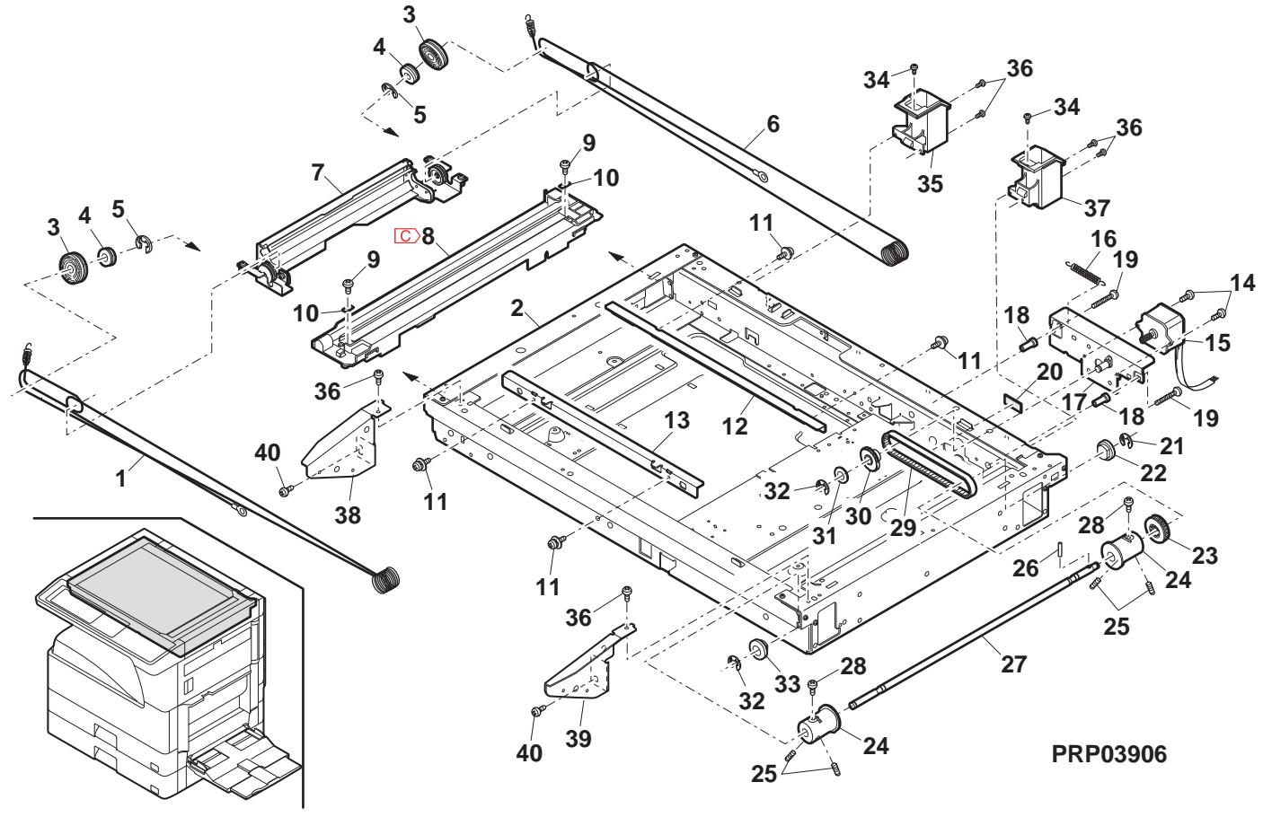
7 光学2 (Cadre optique 2)
| NO. | PARTS CODE | Inter-chang | PRICE RANK | NEW MARK | PART RANK | DESCRIPTION | TR No. | Effective time | |
| Ex. | Ja. | ||||||||
| 1 | PCOVP 0075QSZZ | AE | DS | D | Harness cover ナーか- | ||||
| 2 | XNES 30-24000 | AA | DD | C | Nut(M3) カト | ||||
| 3 | VHPGP 2D03//--18 | AZ | FX | B | Photo sensor(GP2D03) (Inch Series) ナーか- | ||||
| VHPGP 2D07//--18 | BA | FX | B | Photo sensor(GP2D07) (AB Series) ナーか- | |||||
| 4 | DHA i -0347QSPZ | AN | EQ | C | Optical sensor harness (Inch Series) 光学移相方式(光学移相方式) | ||||
| DHA i -0346QSPZ | AP | EQ | C | Optical sensor harness (AB Series) 光学移相方式(光学移相方式) | |||||
| 5 | LHLDW1009ACZZ | AA | DD | C | Clamp(UAMS-05S-2) カフロ | ||||
| 6 | XBBS830P08000 | AA | DD | C | Screw(3×8) フλ | ||||
| 7 | CPWBF 0083QSE5 | AU | EZ | E | Sensor PWB ナー基板 | ||||
| 8 | CDAIU012QS15 | BG | GT | C | Optical base plate | 光学台板 | |||
| 9 | PGUMS0004QSZZ | AA | DJ | C | Table glass cushion | テフロー ハウクルデー | |||
| 10 | XHBS730P06000 | AC | DD | C | Screw(3×6) フλ | ||||
| 11 | VHPGP 2D032//--18 | BA | FX | B | Photo sensor(GP2D032) (Inch Series) ナーか- | ||||
| RSNSZ001QSPZ | BA | FX | B | Photo sensor(GP2D071) (AB Series) ナーか- | |||||
| 12 | XBPS730P08X00 | AA | DD | C | Screw(3×8X) フλ | ||||
| 13 | LPLTP0230QSZZ | AF | DS | C | Open/close sensor fixing plate | 開閉移相-取付板 | |||
| 14 | VHPGP1S73P++--18 | AF | DS | B | Photo sensor(GP1S73P) ナーか- | ||||
| 15 | MSPRD0232QSZZ | AB | DJ | C | Return spring | 復鳬方式(リフロー) | |||
| 16 | MLEVP0077QSZZ | AC | DJ | C | Open/Close actuator | 開閉方式(リフロー) | |||
| 17 | LCRA-0002QSZZ | AC | DJ | C | Mini clamp | ミニヤマ- | |||
| 18 | TLABH0461QSZZ | AG | DS | D | Clean caution label (U.S.A,Canada) 清掃注意方式 | ||||
| TLABH0267QSZZ | AD | DJ | D | Clean caution label (Japan) 清掃注意方式 | |||||
| 19 | LHLDZ0104QSZZ | AD | DJ | C | CL lead holder | CL ナーフロー - | |||
| 20 | PSHEZ0218QSZZ | AC | DJ | C | Edge protect sheet A | IP5'保護方式 A | |||
| 21 | PSHEZ0217QSZZ | AC | DJ | C | CCD harness protect sheet B | CCD ナーフ保護方式 B | |||
| 22 | PSHEZ0448QSZZ | AA | DJ | C | Optical bottom sheet And | 光学底座方式 And | |||
| 24 | PCASZ0010QSZZ | AL | EB | C | Dark box | 暗箱 | |||
| 26 | RCORF0002QSZZ | AE | DS | C | Core(HF57SH35*1) | 7 | |||
| 28 | CLNS-0003RS55 | BP | LE | E | Lens unit | レスロー | |||
| 29 | LX-BZ004QSPZ | AB | DD | C | Screw | 7 | |||
| 30 | DHA i -0345QSZZ | AG | DX | C | CCD harness | CCD ナーフ | |||
| 31 | PSHEZ0108QSZZ | AC | DJ | C | Optical base plate bottom sheet A | 光学台板底座方式 A | |||
| 32 | PSHEZ0219QSZZ | AC | DJ | C | Edge protect sheet B | IP5'保護方式 B | |||
| 33 | LX-BZ0031GCPZ | AB | DD | C | Screw | 7 | |||
| 34 | PSHEZ0254QSZZ | AC | DJ | C | Optical bottom sheet | 光学底座方式 C | |||
| 38 | PSHEZ0273QSZZ | AB | DJ | C | CCD harness protect sheet A | CCD ナーフ保護方式 A | |||
| 39 | PGSK-0008QSPZ | AF | DS | C | Gasket | 7 | |||
| 40 | XWHS740-08100 | AA | DD | C | Washer (AB Series) 7777777777777777777777777777777777777777777777777777777777777777777777777777777777777777777777777777 | ||||
| 41 | PMLT-0094QSZZ | AC | DJ | C | Cushion ORG | 移トORG | |||
| 42 | PSHEZ0443QSZZ | - | AC | DJ | C | OP harness protect sheet F [Missing parts code] OP N-EA保護方式 F | 1st lot | ||
| 43 | PSHEZ0420QSZZ | AC | DJ | C | OP harness protect sheet | OP N-EA保護方式 | |||
| 44 | PTPE-0051QSZZ | AC | DJ | C | OP harness fixing tape | OP N-EA 固定方式 | |||
| 45 | PSHEZ0426QSZZ | AB | DJ | C | OP harness protect sheet B | OP N-EA 保護方式 B | |||
| 46 | PTPE-0063QSZZ | AD | DJ | C | OP harness fixing tape A2 | OP N-EA 固定方式 A2 | |||
| 47 | DHA i -0610QSP1 | BF | GN | C | Operation PWB FFC | 操作基板 FFC | |||
| 48 | PTPE-0050QSZZ | AA | DJ | C | Core fixing tape | 7777777777777777777777777777777777777777777777777777777777777777777777777777777777777777777777777776 | |||
| 49 | PSHEZ0665QSZZ | AC | DJ | C | Optical frame sheet (Japan) 光学方式方式方式方式方式方式方式方式方式方式方式方式方式方式方式方式方式方式方式方式方式方式方式方式方式方式方式方式方式方式方式方式方式方式方式方式方式方式方式方式方式方式方式方式方式方式方式方式方式方式方式方式方式方式方式方式方式方式方式方式方式方式方式方式方式方式方式方式方式方式方式方式方式方式方式方式方式方式方式方式方式方式方式方式方式方式方式方式方式方式方式方式方式方式方式方式方式方式方式方式的方式方式方式方式方式方式方式方式方式方式方式方式方式方式方式方式方式方式方式方式方式方式方式方式方式方式方式方式方式方式方式方式方式方式方式方式方式方式方式方式方式方式方式方式方式方式方式方式方式方式方式方式方式方式方式方式方式方式方式方式方式方式方式方式方式方式方式方式方式方式方式方式方式方式方式方式方式方式方式方式方式方式方式方式方式方式方式方式方式方式方式方式方式方式方式方式方式方式方式方式方法方式方式方式方式方式方式方式方式方式方式方式方式方式方式方式方式方式方式方式方式方式方式方式方式方式方式方式方式方式方式方式方式方式方式方式方式方式方式方式方式方式方式方式方式方式方式方式方式方式方式方式方式方式方式方式方式方式方式方式方式方式方式方式方式方式方式方式方式方式方式方式方式方式方式方式方式方式方式方式方式方式方式方式方式方式方式方式方式方式方式方式方式方式方式方式方式方式方式方式方方式方式方式方式方式方式方式方式方式方式方式方式方式方式方式方式方式方式方式方式方式方式方式方式方式方式方式方式方式方式方式方式方式方式方式方式方式方式方式方式方式方式方式方式方式方式方式方式方式方式方式方式方式方式方式方式方式方式方式方式方式方式方式方式方式方式方式方式方式方式方式方式方式方式方式方式方式方式方式方式方式方式方式方式方式方式方式方式方式方式方式方式方式方式方式方式方式方式方式式方式方式方式方式方式方式方式方式方式方式方式方式方式方式方式方式方式方式方式方式方式方式方式方式方式方式方式方式方式方式方式方式方式方式方式方式方式方式方式方式方式方式方式方式方式方式方式方式方式方式方式方式方式方式方式方式方式方式方式方式方式方式方式方式方式方式方式方式方式方式方式方式方式方式方式方式方式方式方式方式方式方式方式方式方式方式方式方式方式方式方式方式方式方式方式方式方式方式方式方向方式方向方向方向方向方向方向方向方向方向方向方向方向方向方向方向方向方向方向方向方向方向方向方向方向方向方向方向方向方向方向方向方向方向方向方向方向方向方向方向方向方向方向方向方向方向方向方向方向方向方向方向方向方向方向方向方向方向方向方向方向方向方向方向方向方向方向方向方向方向方向方向方向方向方向方向方向方向方向方向方向方向方向方向方向方向方向方向方向方向方向方向方向方向方向方向方向方向方向方向方向的方向方向方向方向方向方向方向方向方向方向方向方向方向方向方向方向方向方向方向方向方向方向方向方向方向方向方向方向方向方向方向方向方向方向方向方向方向方向方向方向方向方向方向方向方向方向方向方向方向方向方向方向方向方向方向方向方向方向方向方向方向方向方向方向方向方向方向方向方向方向方向方向方向方向方向方向方向方向方向方向方向方向方向方向方向方向方向方向方向方向方向方向方向方向方向方向方向方向方向方向方向盘方向盘方向盘方向盘方向盘方向盘方向盘方向盘方向盘方向盘方向盘方向盘方向盘方向盘方向盘方向盘方向盘方向盘方向盘方向盘方向盘方向盘方向盘方向盘方向盘方向盘方向盘方向盘方向盘方向盘方向盘方向盘方向盘方向盘方向盘方向盘方向盘方向盘方向盘方向盘方向盘方向盘方向盘方向盘方向盘方向盘方向盘方向盘方向盘方向盘方向盘方向盘方向盘方向盘方向盘方向盘方向盘方向盘方向盘方向盘方向盘方向盘方向盘方向盘方向盘方向盘方向盘方向盘方向盘方向盘方向盘方向盘方向盘方向盘方向盘方向盘方向盘方向盘方向盘方向盘方向盘方向盘方向盘方向盘方向盘方向盘方向盘方向盘方向盘方向盘方向盘方向盘方向盘方向盘方向盘方向盘方向盘方向盘方向盘方向盘的方向方向方向方向方向方向方向方向方向方向方向方向方向方向方向方向方向方向方向方向方向方向方向方向方向方向方向方向方向方向方向方向方向方向方向方向方向方向方向方向方向方向方向方向方向方向方向方向方向方向方向方向方向方向方向方向方向方向方向方向方向方向方向方向方向方向方向方向方向方向方向方向方向方向方向方向方向方向方向方向方向方向方向方向方向方向方向方向方向方向方向方向方向方向方向方向方向方向方向方向盘的方向方向盘方向盘方向盘方向盘方向盘方向盘方向盘方向盘方向盘方向盘方向盘方向盘方向盘方向盘方向盘方向盘方向盘方向盘方向盘方向盘方向盘方向盘方向盘方向盘方向盘方向盘方向盘方向盘方向盘方向盘方向盘方向盘方向盘方向盘方向盘方向盘方向盘方向盘方向盘方向盘方向盘方向盘方向盘方向盘方向盘方向盘方向盘方向盘方向盘方向盘方向盘方向盘方向盘方向盘方向盘方向盘方向盘方向盘方向盘方向盘方向盘方向盘方向盘方向盘方向盘方向盘方向盘方向盘方向盘方向盘方向盘方向盘方向盘方向盘方向盘方向盘方向盘方向盘方向盘方向盘方向盘方向盘方向盘方向盘方向盘方向盘方向盘方向盘方向盘方向盘方向盘方向盘方向盘方向盘方向盘方向盘方向盘方向盘方向盘 方向 方向 方向 方向 方向 方向 方向 方向 方向 方向 方向 方向 方向 方向 方向 方向 方向 方向 方向 方向 方向 方向 方向 方向 方向 方向 方向 方向 方向 方向 方向 方向 方向 方向 方向 方向 方向 方向 方向 方向 方向 方向 方向 方向 方向 方向 方向 方向 方向 方向 方回 方回 方回 方回 方回 方回 方回 方回 方回 方回 方回 方回 方回 方回 方回 方回 方回 方回 方回 方回 方回 方回 方回 方回 方回 方回 方回 方回 方回 方回 方回 方回 方回 方回 方回 方回 方回 方回 方回 方回 方回 方回 方回 方回 方回 方回 方回 方回 方回 方回 方记 方记 方记 方记 方记 方记 方记 方记 方记 方记 方记 方记 方记 方记 方记 方记 方记 方记 方记 方记 方记 方记 方记 方记 方记 方记 方记 方记 方记 方记 方记 方记 方记 方记 方记 方记 方记 方记 方记 方记 方记 方记 方记 方记 方记 方记 方记 方记 方记 方记 方記 方记 方记 方记 方记 方记 方记 方记 方记 方记 方记 方记 方记 方记 方记 方记 方记 方记 方记 方记 方记 方记 方记 方记 方记 方记 方记 方记 方记 方记 方记 方记 方记 方记 方记 方记 方记 方记 方记 方记 方记 方记 方记 方记 方记 方记 方记 方记 方记 方记 方 | ||||
7 光学2 (Cadre optique 2)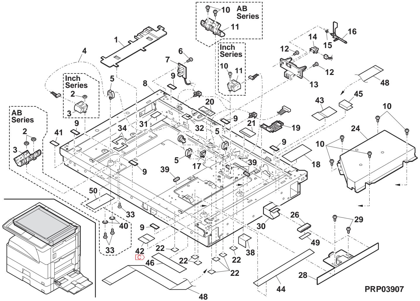
8 中間フレーム部 (Section du châssis intermédiaire)
| NO. | PARTS CODE | Inter-chang | PRICE RANK | NEW MARK | PART RANK | DESCRIPTION | TR No. | Effective time | |
| Ex. | Ja. | ||||||||
| 1 | DUNTK0616RSZZ | BV | NU | E | LSU unit(Include No.101) | LSU ハチト | |||
| 2 | XEPST30P14X00 | AB | DD | C | Screw(3×14X) | ごλ | |||
| 5 | MARMPO025QSZZ | AD | DJ | C | Separator paw arm | 剥離爪7-4L | |||
| 6 | XEBS730P10000 | AC | DD | C | Screw(3×10) | ごλ | |||
| 7 | CHA i-0356RS51 | AL | EB | C | MC harness | MC ハチト | |||
| 8 | CHA i-0603RS51 | AN | EQ | C | GRID-MCFB harness | GRID-MCFB ハチト | |||
| 9 | LHLDZ0057QSZ1 | AH | DX | C | High voltage terminal holder B | 高压端子総径-B | |||
| 10 | DHA i-0506QSPZ | AQ | EQ | C | LSU interface harness | LSU 中縫を検 | |||
| 11 | MSPRD0190QSZ2 | AD | DJ | C | High voltage terminal holder spring saw teeth L | 高压端子総径-A ロリフ鉛齒L | |||
| 12 | MSPRD0191QSZ2 | AD | DJ | C | High voltage terminal holder spring grid L | 高压端子総径-A ロリフ鉛齒L | |||
| 13 | MSPRD0192QSZ2 | AD | DJ | C | High voltage terminal holder spring case L | 高压端子総径-A ロリフ鉛齒L | |||
| 14 | DHA i-0606QSPZ | - | BT | MW | C | AN2R ILSW interface harness [Missing parts code] | AN2R ILSW 中縫を検 | ||
| 15 | LX-BZ0020QSPZ | AB | DD | C | Step screw | 段比λ | |||
| 16 | LPLTM0424QSZ | AD | DJ | C | CRUM connector fixing plate | CRUM ハチト 取付板 | |||
| 18 | XRESP50-06000 | AA | DD | C | E type ring(E5) | E ハチト | |||
| 19 | PCLC-0030QSZZ | AQ | EQ | B | PS clutch | PS ハチト | |||
| 20 | DHA i-0590QSPZ | - | BT | NE | C | AN2R DV interface harness TW [Missing parts code] | AN2R DV 中縫を検 | ||
| 27 | XBBSS30P05000 | AA | DD | C | Screw(3×5) | ごλ | |||
| 28 | LHLDZ0085QSZZ | AE | DJ | C | TR terminal holder | TR端子総径- | |||
| 29 | LPLTM0248QSZ1 | AD | DJ | C | TR terminal plate | TR端子板 | |||
| 30 | NROLR0089QSZ3 | AY | FQ | C | PS transport roller Ref (Except Japan) | PS搬送ローロ-Ref | |||
| NROLR0135QSZ2 | AZ | FQ | C | PS transport roller Ref (Japan) | PS搬送ローロ-Ref | ||||
| 31 | NBRGC0018QSZZ | AD | DJ | C | Bearing | 軸受 | |||
| 32 | PCOVP0062QSZZ | AD | DJ | D | ILSW cover | ILSW 加" | |||
| 33 | LSTPP0010QSZZ | AD | DJ | C | Right door stopper | 右口" ハチト" | |||
| 34 | MSPRC020QSZZ | AB | DJ | C | Stopper spring | トナマリドリル" | |||
| 35 | MLEVP0071QSZZ | AD | DJ | C | ILSW lever | ILSW ハチト | |||
| 36 | CSW-M0007RS56 | AP | EQ | B | Interlock switch | 側部-ロリフ鉛。 | |||
| 37 | LHLDZ0065QSZ1 | AF | DS | C | ILSW holder | ILSW ハチト | |||
| 38 | MSPRT0221QSZZ | AB | DJ | C | ILSW spring | ILSW ハチト | |||
| 40 | JKNBZ0006QSZZ | AD | DJ | D | PS knob | PS ハチト | |||
| 41 | XBPSS30P08KS0 | AB | DD | C | Screw(3×8KS) | ごλ | |||
| 42 | XBPSC30P06ES0 | AA | DD | C | Screw(3×6ES) | ごλ | |||
| 43 | LFRM-D0037QSZ6 | BA | GD | D | Middle frame | 中間ルトム | |||
| 44 | XRESP60-08000 | AA | DD | C | E type ring(E6) | E ハチト | |||
| 45 | RMOTD0023QSZZ | AZ | FX | B | Toner motor | トナマリド- | |||
| 46 | MSPRC0024QSZ1 | AC | DJ | C | Hopper spring | トナマリドリル" | |||
| 47 | NCPL-0011QSZZ | AC | DJ | C | Hopper coupling | トナマリドリル" | |||
| 50 | RPLU-0024QSZZ | AM | EG | B | Pawl solenoid | 爪レフト | |||
| RPLU-0024QSPZ | 1 | AM | EG | B | Pawl solenoid | 爪レフト | |||
| 51 | MSPRC1318FCZ1 | AA | DJ | C | Manual paper feed spring B | 手差しろじ" ハチト" | |||
| 52 | LPiNS0025QSZZ | AC | DJ | C | TN guide pin A (Inch series,AB Series agency) | TNがト" ハチトA | |||
| LPiNS0026QSZZ | AC | DJ | C | TN guide pin B (Except Inch series,AB Series agency) | TNがト" ハチトB | ||||
| LPiNS0028QSZZ | AD | DJ | C | TN guide pin C (Japan) | TNがト" ハチトC | ||||
| 53 | XEBS740P10000 | AA | DD | C | Screw(4×10) | ごλ | |||
| 54 | XEBS730P06000 | AA | DD | C | Screw(3×6) | ごλ | |||
| 55 | DHA i-0354QSPZ | AG | DS | C | TC harness | TC ハチト | |||
| 56 | DHA i-0605QSPZ | - | BS | MW | C | DHV harness [Missing parts code] | DHV ハチト | ||
| 63 | MSPRC0271QSZZ | AC | DJ | C | Earth spring | アスフリド" | |||
| 64 | XEPST23P12000 | AA | DD | C | Screw(3×12) | ごλ | |||
| 65 | PSHEZ0394QSZ1 | AB | DJ | C | Solenoid sound proof sheet | ルフリド消音材 | |||
| 66 | QSW-B0017QSZZ | AF | DS | B | Tray detect switch | ルフリド消音材 | |||
| 67 | CPLTM0160RS59 | BH | HC | E | Drive unit [MX-M260/M260N/M260FG/M260FP,AR-5726] 驅動電気灯 | 驱动電気灯 | |||
| CPLTM0160RS60 | BH | HC | E | Drive unit [MX-M310/M310N/M310FG/M310FP,AR-5731] 驅動電気灯 | |||||
| 70 | PSPAZ0041QSZZ | AA | DJ | C | Solenoid spacer | ルフリド" ハチト" | |||
| 74 | PMLT-0120QSZ1 | AL | EB | C | Fusing cushion A [MX-M310/M310N/M310FG/M310FP,AR-5731] 定着体A | ||||
| 75 | PMLT-0116QSZ | AE | DJ | C | Fan cover cushion L | 中縫はりトL | |||
| 76 | PMLT-0117QSZ | AD | DJ | C | Fan cover cushion R | 川渓はりトR | |||
| 77 | PCOVPI0108QSZ1 | AK | DX | C | Fan cover | 川渓はりト" | |||
| 78 | XHBS730P08000 | AB | DD | C | Screw | ごλ | |||
| 79 | XHBS730P20000 | AB | DD | C | LSU cooling fan screw(3×20) | LSU 冷却7%" ハチト" | |||
| 80 | NFANP0081FCZZ | BA | FX | B | LSU cooling fan | LSU 冷却7%" | |||
| 81 | PLTM0392QSZZ | AK | DX | C | Fan plate | 川渓はりト | |||
| 82 | QCNCMI000FCZ | AC | DJ | C | Interface connector(BU03P-TR-PH) | 中縫はりト | |||
| 83 | LBNDJ0071FCZZ | AC | DJ | C | Cable band(RSG-100) | 川渓はりト" | |||
| 84 | PTPE-0062QSZZ | AD | DJ | C | Fan plate tape | FAN ハチト" | |||
| 85 | XEBS740P12000 | AA | DD | C | Screw(4×12) | ごλ | |||
| 86 | XEPST30P14X00 | AB | DD | C | Screw(3×14X) | ごλ | |||
| 87 | PCOVPI0109QSZ | AN | EG | C | LSU cover | LSU 加" | |||
| 88 | PMLT-0118QSZ1 | AC | DJ | C | LSU cover cushion L | LSU 加" - ハチトL | |||
| 89 | PMLT-0148QSZ | AB | DJ | C | LSU cover cushion R | LSU 加" - ハチトR | |||
8 中間フレーム部 (Section du châssis intermédiaire)
| NO. | PARTS CODE | Inter-changese | PRICE RANK | NEWMARK | PARTRANK | DESCRIPTION | TR No. | Effective time | |
| Ex. | Ja. | ||||||||
| 91 | PCōVP 0 1 4 3 QS Z Z | AH | DX | D | Process air intake duct cover 7" 吐吸気が外加- | ||||
| 92 | PDUC-0 0 1 0 QS Z Z | AH | DX | D | Process air intake duct 7" 吐吸気が外 | ||||
| 93 | DHA i - 0 6 0 9 QSP Z | AK | DX | C | AN2R PS fan harness AN2R PS7" フロー-ス | ||||
| 101 | RMōTN 0 0 5 5 QSP Z | BL | HG | B | Polygon motor(for LSU) 7" 归TS-ス- | ||||
8 中間フレーム部 (Section du châssis intermédiaire)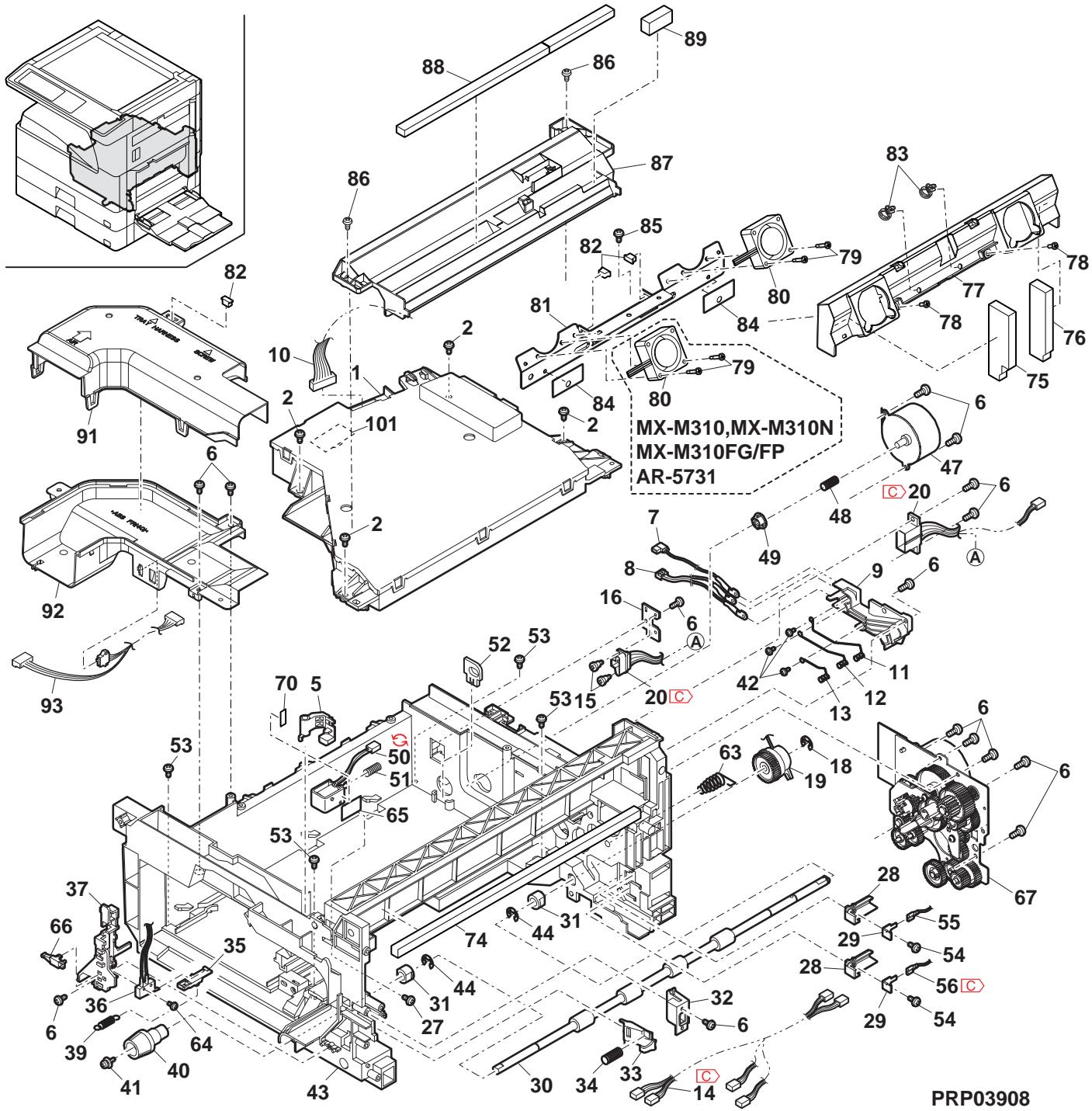
550 550 cassette unit)
| NO. | PARTS CODE | Inter-changec | PRICE RANK | NEW MARK | PART RANK | DESCRIPTION | TR No. | Effective time | |
| Ex. | Ja. | ||||||||
| 1 | LPLTP0159QSZZ | AD | DJ | C | Cassette rear edge plate 保ト後端板 | ||||
| 2 | LHLDW1226FCZZ | AB | DJ | C | Turn fastener 保フロー | ||||
| 3 | LPLTM0179QSZ1 | AR | EQ | C | Rotation plate 回転板 | ||||
| 4 | PSHEZ0274QSZZ | AC | DJ | C | Rotation plate sheet 回転板←上 | ||||
| 5 | GCASP0006QSZZ | BA | FX | D | 550 cassette 550保ト | ||||
| 6 | PGiDM070QSZ1 | AM | EG | D | Guide F 保フローF | ||||
| 7 | PTPE-0021QSZ1 | - | AA | DJ | C | GID tape [Missing parts code] GID 画面→J | 1st lot | ||
| 8 | LPLTM0181QSZ1 | AB | DJ | C | Side plate guide F 侧板"↓F | ||||
| 9 | PGiDM071QSZZ | AL | EB | D | Guide R 保フR | ||||
| 10 | LX-BZ1144FCPZ | AA | DD | C | Screw 保λ | ||||
| 11 | NGERH0193FCZZ | AB | DD | C | UC manual paper feed gear UC手差じ☆ | ||||
| 12 | MSPRC2631FCZZ | AC | DJ | C | Fusing pressure spring 定着加压 ムリド | ||||
| 13 | MLEVP0755FCZ1 | AE | DJ | C | Side plate F lever 侧板F↓- | ||||
| 14 | LX-BZ0833FCPZ | AC | DD | C | Screw 保λ | ||||
| 15 | PSHEZ0244QSZZ | AC | DJ | C | Cassette sheet 保ト←上 | ||||
| 16 | XRESP70-08000 | AA | DD | C | E type ring(E7) E リス" | ||||
| 17 | NGERH0108QSZZ | AD | DJ | C | Lift gear(22T) 保フ←上 | ||||
| 18 | MSPRC0354QSZZ | AC | DJ | C | Lift gear spring ムリフ"はフリド | ||||
| 19 | NSFTZ0047QSZ1 | AK | EB | C | Lift shaft ムリフ←上 | ||||
| 20 | LPLTM0180QSZ1 | AE | DS | C | Lift plate ムリフ←上 | ||||
| 21 | NBRGP0041GCZZ | AD | DJ | C | Bearing 輸受 | ||||
| 22 | XEBS74010000 | AA | DD | C | Screw(4×10) 保λ | ||||
| 23 | GCOV-0282FCZZ | AH | DX | D | Cassette handle cover P2 保ト取手か"-P2 | ||||
| 24 | XBPS740P08KS0 | AB | DD | C | Screw(4×8KS) 保λ | ||||
| 25 | PSHEZ5948FCZZ | AD | DJ | C | Cassette handle sheet P2 保ト取手←上P2 | ||||
| 27 | LPLTM0277QSZZ | AC | DJ | C | Side plate guide R 侧板"↓R | ||||
| 28 | JHNDP0013QSZZ | AT | EZ | C | Cassette panel AN2R 保ト←上AN2R | ||||
| 29 | XEBS730P08000 | AC | DD | C | Screw(3×8) 保λ | ||||
| 30 | TCADZ0549QSZZ | - | AE | DS | D | Size display card [Missing parts code](Inch Series) 保フ"表示←上" | 1st lot | ||
| TCADZ0550QSZZ | AE | DS | D | Size display label (AB Series except Japan) 保フ"表示←上" | |||||
| 31 | TLABZ0335QSZZ | AD | DJ | D | Paper seal label (Japan) 用紙封止ら"-J | ||||
| 501 | CCASP0006RS79 | - | BF | GN | E | 2nd 550 cassette unit[Missing parts code] 2nd 550保ト←上 | 1st lot | ||
| (Unit) | |||||||||
| 901 | CCASP0006RS59 | BH | GX | E | 550 cassette unit(Without No.30) 550保ト←上(No.30を除く) | ||||
9 550 加入二(550 cassette unit)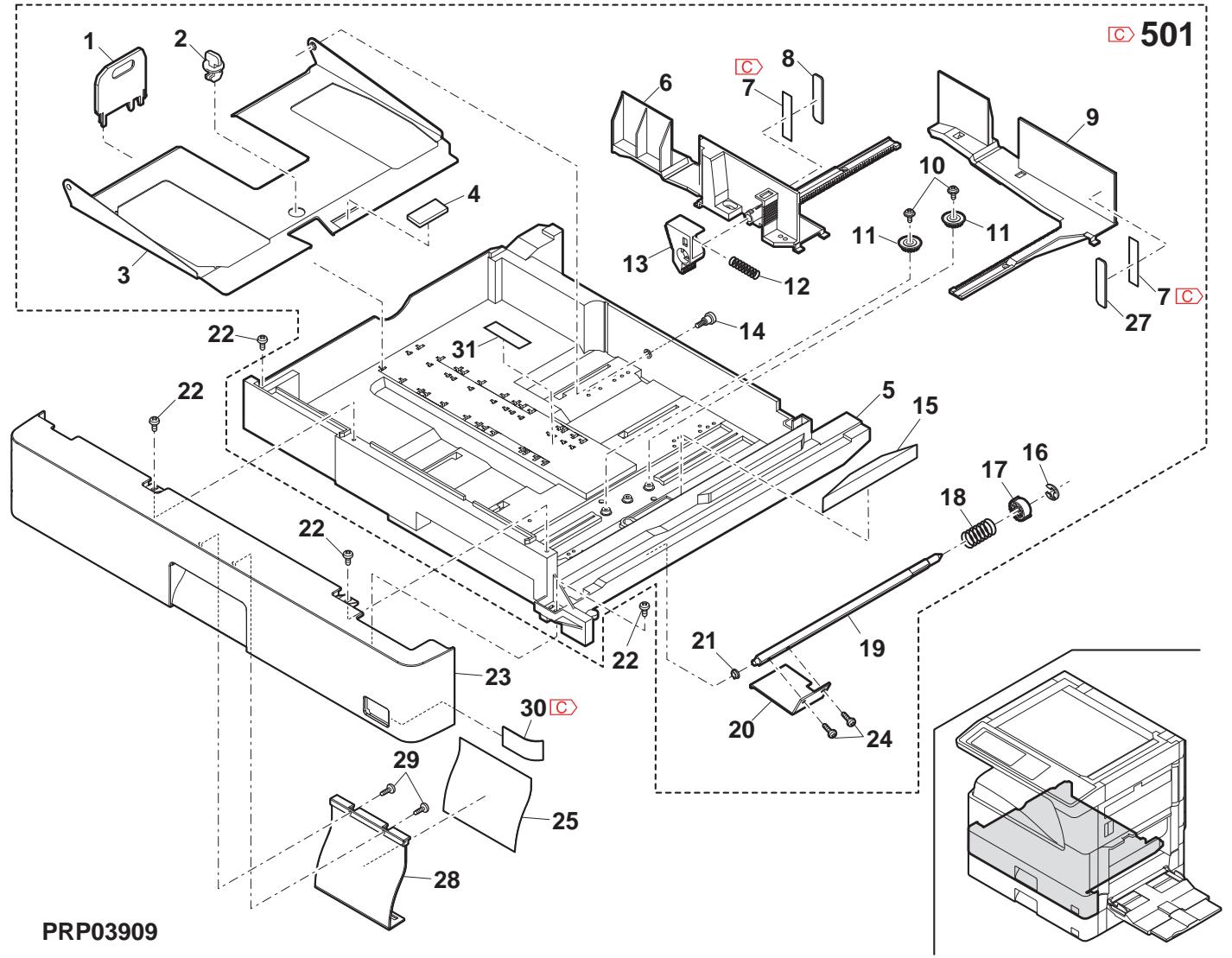
10 結紙部(Paper feed section)
| NO. | PARTS CODE | Inter-changese | PRICE RANK | NEW MARK | PART RANK | DESCRIPTION | TR No. | Effective time | |
| Ex. | Ja. | ||||||||
| 1 | XEBS 7 30 P 1 0000 | AC | DD | C | Screw(3×10) | £'λ | |||
| 2 | CPWBF 0 081 QSE2 | AP | EQ | E | Cassette sensor PWB | 加さルリフ基板 | |||
| 3 | MLEVP 0 064 QSZZ | AD | DJ | C | Paper detect actuator | 紙換知7円工-4 | |||
| 4 | MLEVP 0 063 QSZ1 | AD | DJ | C | Upper limit detect actuator | 上限核知刀工-4 | |||
| 5 | MLEVP 0 056 QSZZ | AC | DJ | C | P-IN actuator | P-IN7円工-4 | |||
| 6 | MSPRD 0 201 QSZZ | AC | DJ | C | Paper feed in actuator spring | 入紙7円工-4 空洞-4 | |||
| 7 | PCOVP 0 064 QSZZ | AD | DJ | D | Solenoid cover | ルフローロ-4 | |||
| 8 | RPLU 0 026 QSZ1 | AR | EQ | B | Paper feed solenoid | 絡紙ルフ-4 | |||
| RPLU - 0 026 QSP 1 | 1 | AR | EQ | B | Paper feed solenoid | 絡紙ルフ-4 | |||
| 9 | MARP 0 026 QSZZ | AD | DJ | C | Solenoid arm | ルフローロ-4 | |||
| 10 | NROLR 0 1 33 QSZZ | AM | EG | A | Pick up roller | £' イフローロ-4 | |||
| 11 | MARP 0 019 QSZZ | AD | DJ | C | Pick up arm F | £' イフローロ-4 F | |||
| 13 | NGERH0 9 90 FCZZ | AB | DJ | C | Gear(16T) | £' λ | |||
| 14 | NROLR 0 1 32 QSZ1 | AR | EQ | C | Paper feed roller AND2 | 絡紙ローロ-AND2 | |||
| 15 | MARP 0 021 QSZZ | AD | DJ | C | Pick up arm R | £' イフローロ-4 R | |||
| 16 | LP i N - 0 026 MCZZ | AA | DD | C | Spring pin(φ2-8) | £' イフローロ-4 | |||
| 17 | NGERH0 1 07 QSZZ | AD | DJ | C | Paper feed gear(20T) | 絡紙ローロ-4 | |||
| 18 | MSPRD 0 389 QSZZ | AC | DJ | C | Pick up roller pressure spring | £' イフローロ-4 加压スフ-4 | |||
| 19 | NBRGC0 1 00 FCZ1 | AC | DJ | C | Bearing 6 | ^ ナリス6 | |||
| 20 | NGERH0 0 97 QSZZ | AF | DS | C | 2nd joint gear | 2nd連軸+4 | |||
| 21 | DHA i - 0 350 QSPZ | AG | DX | C | Cassette sensor harness | 加さルリフ-4 | |||
| 22 | QSW-B 0 017 QSZZ | AF | DS | B | Tray detect switch | 徒接知4 | |||
| 23 | NGERH0 1 56 QSZZ | AD | DJ | C | Paper feed clutch gear(42T) | 絡紙ローロ-4 | |||
| 24 | MSPRC0 2 09 QSZ1 | AC | DJ | C | Solenoid spring | ルフローロ-4 | |||
| 25 | XRESP 40 - 0 60 00 | AA | DD | C | E type ring(E4) | E ナリス | |||
| 27 | XRESP 50 - 0 60 00 | AA | DD | C | E type ring(E5) | E ナリス | |||
| 28 | PCLC - 0 024 QSZZ | AX | FG | B | Paper feed clutch(42T) | 絡紙ローロ-4 | |||
| 29 | NSFT Z 0 080 QSZ1 | AG | DS | C | Paper feed roller shaft | 絡紙ローロ-4 轴 | |||
| 30 | VHPSG2481 ++ -1 | AE | DS | B | Photo sensor(SG2481) | 打交道-4 | |||
| 31 | DHA i - 0 399 QSPZ | AF | DS | C | Manual paper feed empty harness | 手差L 工厂工-4 消音材 C | |||
| 32 | XEBS T 30 P 0 80 00 | AC | DD | C | Screw(3×8) | £' λ | |||
| 34 | LPLTP 0 1 92 QSZZ | AK | DX | C | Dehumidify heater fixing plate | (Japan)除湿比-4 取付板 | |||
| 35 | RHT - 0 0 0 6 QSZZ | AQ | EQ | B | Dehumidify heater | (Japan)除湿比-4 | |||
| 36 | PSHEZ 0 391 QSZ1 | AC | DJ | C | Paper feed solenoid sound proof A | 絡紙ルフ-4 消音材 A | |||
| 37 | PSHEZ 0 392 QSZ1 | AB | DJ | C | Paper feed solenoid sound proof B | 絡紙ルフ-4 消音材 B | |||
| 38 | PSHEZ 0 393 QSZ1 | AA | DJ | C | Paper feed solenoid sound proof C | 絡紙ルフ-4 消音材 C | |||
| 39 | |||||||||
| 40 | |||||||||
| 41 | |||||||||
| 42 | |||||||||
| 43 | |||||||||
| 44 | |||||||||
| 45 | |||||||||
| 46 | |||||||||
| 47 | |||||||||
| 48 | |||||||||
| 49 | |||||||||
| 50 | |||||||||
| 51 | |||||||||
| 52 | |||||||||
| 53 | |||||||||
| 54 | |||||||||
| 55 | |||||||||
| 56 | |||||||||
| 57 | |||||||||
| 58 | |||||||||
| 59 | |||||||||
| 60 | |||||||||
| 61 | |||||||||
| 62 | |||||||||
| 63 | |||||||||
| 64 | |||||||||
| 65 | |||||||||
| 66 | |||||||||
| 67 | |||||||||
| 68 | |||||||||
| 69 | |||||||||
| 70 | |||||||||
| 71 | |||||||||
| 72 | |||||||||
| 73 | |||||||||
| 74 | |||||||||
| 75 | |||||||||
| 76 | |||||||||
| 77 | |||||||||
| 78 | |||||||||
| 79 | |||||||||
| 80 | |||||||||
| 81 | |||||||||
| 82 | |||||||||
| 83 | |||||||||
| 84 | |||||||||
| 85 | |||||||||
| 86 | |||||||||
| 87 | |||||||||
| 88 | |||||||||
| 89 | |||||||||
| 90 | |||||||||
| 91 | |||||||||
| 92 | |||||||||
| 93 | |||||||||
| 94 | |||||||||
| 95 | |||||||||
| 96 | |||||||||
| 97 | |||||||||
| 98 | |||||||||
| 99 | |||||||||
| 100 | |||||||||
10 給紙部(Paper feed section)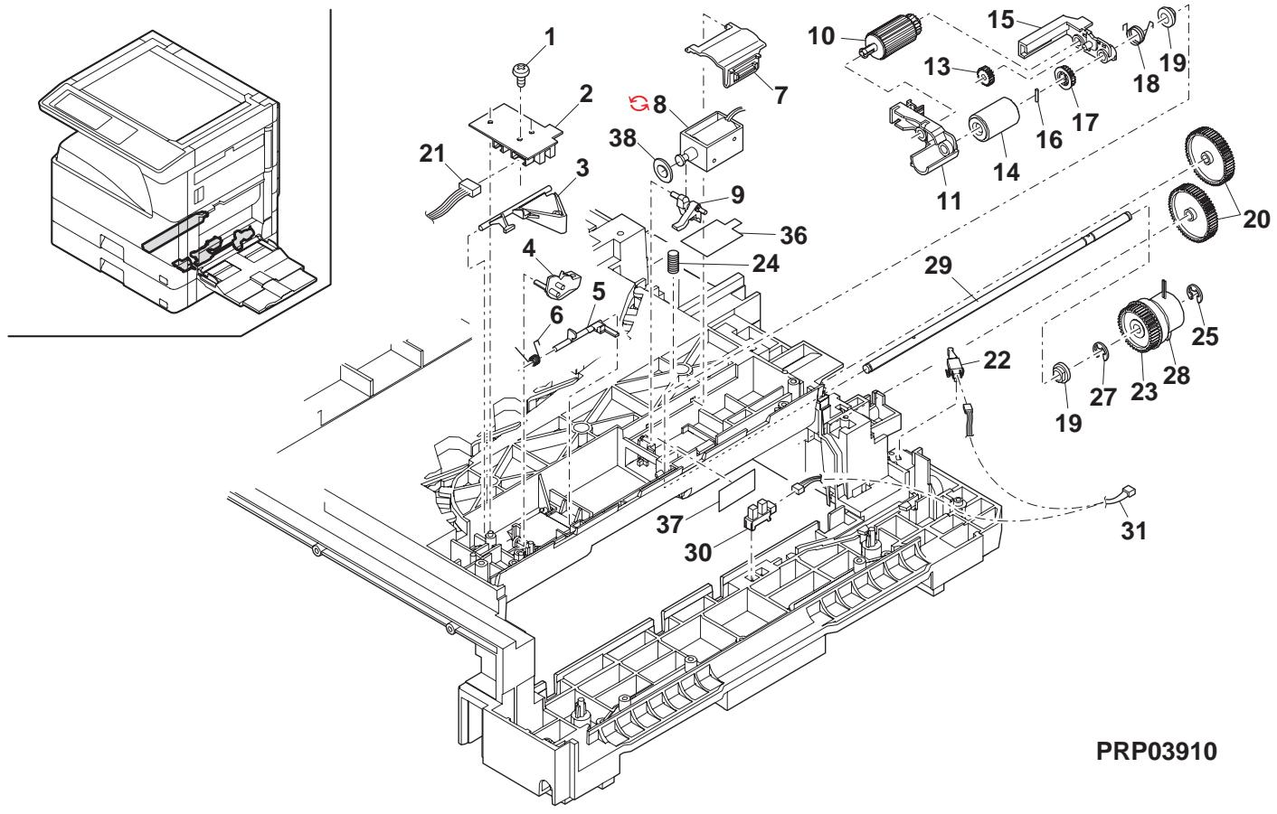
11 搬送部(Paper transfer section)
| NO. | PARTS CODE | Inter-changese | PRICE RANK | NEW MARK | PART RANK | DESCRIPTION | TR No. | Effective time | |
| Ex. | Ja. | ||||||||
| 1 | XEBS740P12000 | AA | DD | C | Screw(4×12) | b'λ | |||
| 2 | PCOVP0053QSZ6 | AK | EB | D | Middle frame cover | 中間ル-あら"- | |||
| 3 | MSPRD0194QSZ1 | AD | DJ | C | PS earth spring LP | PS 7-λλ''Lp''LP | |||
| 4 | MSPRC0291QSZZ | AC | DJ | C | PS pressure spring | PS 加压λ''Lp'' | |||
| 5 | NSFTZ0065QSZ1 | AD | DJ | C | PS sub shaft | PS 從動軸 | |||
| 6 | NKOM-0006QSZZ | AC | DJ | C | PS collar(φ13.5) | PS ハ | |||
| 7 | PSHEZ0133QSZZ | AD | DJ | C | Paper feed sheet | 鉛鉛用ト | |||
| 8 | XEBS740P10000 | AA | DD | C | Screw(4×10) | b'λ | |||
| 9 | PG i DM0067QST1 | AP | EQ | C | Base plate paper feed guide | 台板絵紙''ト'' | |||
| 10 | MSPRD0233QSZ1 | AC | DJ | C | MF actuator spring | MF 7''Lp''-λ''Lp'' | |||
| 11 | MLEVP0023QSZZ | AE | DS | C | MF actuator | MF 7''Lp''-λ''Lp'' | |||
| 12 | MLEVP004QSZZ | AE | DS | C | MF actuator 2 | MF 7''Lp''-2 | |||
| 13 | LPLTP0348QSZZ | AC | DJ | C | Separator plate | 挪きレト | |||
| 14 | MSPRC0301QSZZ | AD | DJ | C | Pressure plate spring | 压着板λ''Lp'' | |||
| 15 | PFTA-0019QSZZ | AE | DS | D | Pressure plate cover | 压着板盖 | |||
| 16 | XEBS730P10000 | AC | DD | C | Screw(3×10) | b'λ | |||
| 17 | PSHEZ0242QSZ1 | AH | DX | C | Pressure plate sheet | 压着板ト | |||
| 18 | LRALP0008QSZ | AN | EG | C | Base plate rail R | 台板レトR | |||
| 19 | VHPGP1S73P+-18 | AF | DS | B | Photo sensor(GP1S73P) | フローナー | |||
| 20 | DHA i -0398QSPZ | AE | DS | C | Manual paper feed P-IN harness | 手差 L-P-IN-ス | |||
| 21 | MSPRD0202QSZZ | AB | DJ | C | Manual paper feed P-IN actuator spring | 手差 L-P-IN 7''Lp''-λ''Lp'' | |||
| 22 | MLEVP0057QSZZ | AC | DJ | C | Manual paper feed P-IN actuator | 手差 L-P-IN 7''Lp''-λ''Lp'' | |||
| 23 | PSHEZ0515QSZZ | AG | DX | A | Separator sheet | 挪きレト | |||
| 24 | LPLTP0409QSZZ | AC | DJ | C | Separator plate AND2 | 挪きアリトAND2 | |||
| 25 | PCOVP0088QSZ1 | AD | DJ | D | Plate cover | 7''Lp''- | |||
| 26 | MSPRC0270QSZZ | AB | DJ | C | Separator plate spring | 挪きアリト 7''Lp'' | |||
| 27 | NKOM-0005QSZZ | AC | DJ | C | Cassette guide collar | 加さはト''ト'' | |||
| 28 | NSFTZ0048QSPZ | AF | DS | C | Cassette collar shaft | 加さはト・轴 | |||
| 29 | XBPS730P08KS0 | AB | DD | C | Screw(3×8KS) | b'λ | |||
| 30 | PSHEZ0301QSZZ | AC | DJ | C | Rail R side sheet F | レルR p''Lp''-F | |||
| 31 | PSHEZ0302QSZZ | AC | DJ | C | Rail R side sheet R | レルR p''Lp''-R | |||
| 32 | PSHEZ0463QSZZ | AD | DJ | C | Front separator sheet | 前摺レト | |||
| 33 | PSPÖ-0026QSZZ | AA | DJ | C | MF ACT cushion | MF ACT λ''Lp'' | |||
| 34 | LHLDZ0094QSZZ | AC | DJ | C | PS pressure holder | PS 加压はト" | |||
| 35 | MSPRC0292QSZZ | AC | DJ | C | PS follower connect spring | PS 従勤接続 7''Lp'' | |||
| 36 | MSPRD0287QSZZ | AC | DJ | C | Paper feed sub roller spring | 給紙補助 7''Lp''-Lp'' | |||
| 37 | NROLP0087QSZZ | AD | DJ | C | Paper feed sub roller | 給紙補助レト- | |||
| 38 | NSFTZ0101QSZZ | AC | DJ | C | Paper feed sub roller shaft | 給紙補助レト-轴 | |||
| 39 | PSHEZ0314QSZ2 | AF | DS | C | Toner protect sheet N | け一飛散封止 7''Lp''N | |||
| 40 | LBRC-0012QSZZ | AD | DJ | C | Manual paper feed sub collar bracket | 手差 L辅助加 7''Lp''-Lp'' | |||
| 41 | NKOM-0011QSZZ | AC | DJ | C | Manual paper feed sub collar | 手差 L辅助加 | |||
| 42 | NSFTZ0101QSZZ | AC | DJ | C | Paper feed sub roller shaft | 給紙補助レト-轴 | |||
| 43 | MSPRD03008000 | AC | DD | C | Separator guide plate | 挪きアリト | |||
| 44 | XEBS730P08000 | AC | DD | C | Screw(3×8) | b'λ | |||
| 45 | LPLTP0396QSZ1 | AD | DJ | C | Separator guide plate | 挪きアリト | |||
| 46 | LX-WZ0064FCZZ | AA | DD | C | Push nut(M3) | 7''Lp''-Lp'' | |||
| 47 | PG i DM0186QSZZ | AK | DX | D | Cover guide | 加''Lp''-Lp'' | |||
| 48 | LPLTP0622FCZZ | AC | DJ | C | M4 plate N | M4 7''Lp''N | |||
| 49 | CG i DM0067RS56 | - | AX | FG | E | Base plate paper feed guide unit [Missing parts code] | 台板絵紙 7''Lp''-工部 | ||
| 50 | CCOVP0053RS55 | - | AS | EZ | E | Middle frame cover unit [Missing parts code] | 中間ル-ム 7''Lp''-工部 | ||
| 51 | CCOVP0088RS56 | - | AN | EQ | E | Plate cover unit [Missing parts code] | 7''Lp''-工部 | ||
| 52 | CCOVP0088RS56 | - | AN | EQ | E | Separation plate unit | 分離アリト工部 | ||
11 搬送部(Paper transfer section) PRP03911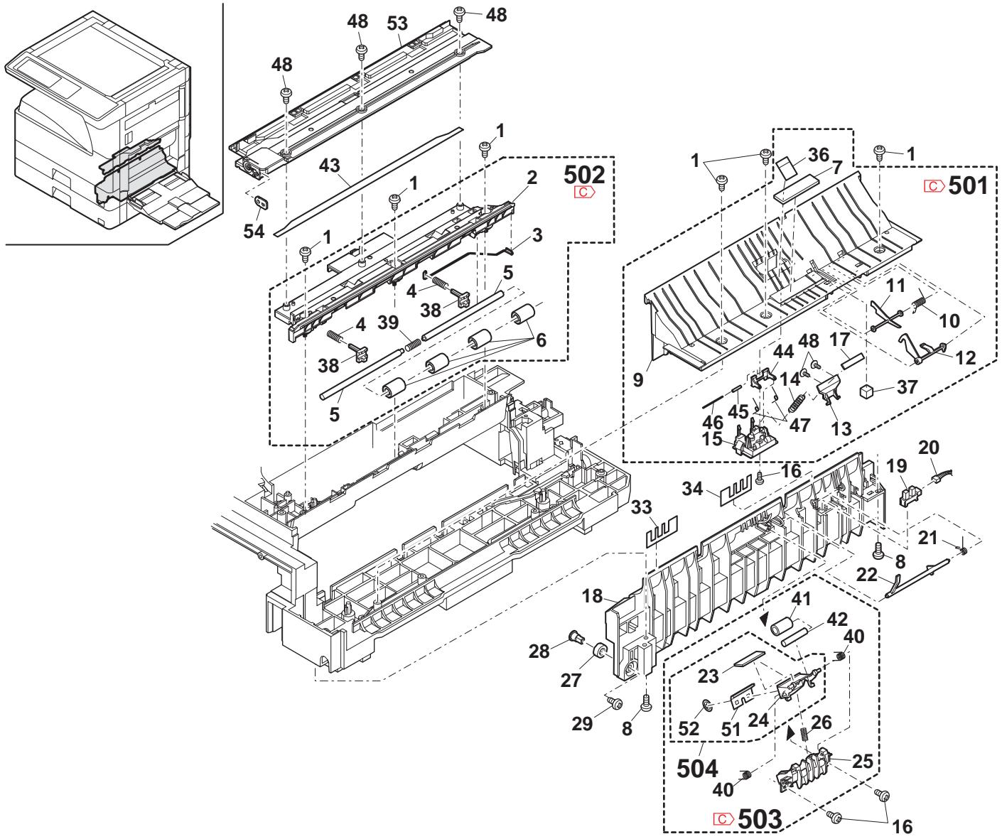
12 トトトト(Side door unit)
| NO. | PARTS CODE | Inter-changese | PRICE RANK | NEW MARK | PART MARK | DESCRIPTION | TR No. | Effective time | |
| Ex. | Ja. | ||||||||
| 1 | MLEVP0058QSTZ | - | AD | DJ | C | Lock lever | torlal - | ||
| 2 | GDOR-0002QSTD | - | AV | FG | D | Right door [Missing parts code] | 右下? | 1st lot | |
| 3 | XRESP40-06000 | - | AA | DD | C | E type ring(E4) | E リル - | ||
| 4 | LBSHZ0303FCZZ | - | AC | DJ | C | M bushing C | M フリフNGC | ||
| 5 | NGERH0074QSZZ | - | AD | DJ | C | DUP roller drive gear | DUP ユーネー 驱動技 | ||
| 6 | LPINS0133FCZZ | - | AA | DD | C | Pin(2×10) | awilful - | ||
| 7 | PTME-0020QSZ1 | - | AC | DJ | C | Lock pawl | tori爪 | ||
| 8 | MSPRD0222QSZZ | - | AC | DJ | C | Lock pawl spring | tori爪 tori爪 | ||
| 9 | MARP0043QSZZ | - | AC | DJ | C | Lock pawl arm | tori爪牙头 | ||
| 10 | NSFTZ0055QSZ3 | - | AH | DX | C | Lock pawl shaft | tori爪牙头 | ||
| 11 | XRESP30-06000 | - | AA | DD | C | E type ring(E3) | E リル - | ||
| 12 | NRLOP0036QSZZ | - | AP | EQ | C | DUP transport roller | DUP 搬送tori爪 | ||
| 13 | XPSSJ20-07000 | - | AA | DD | C | Spring pin (φ2-7) | tori爪 tori爪 | ||
| 14 | MSPRT0279QSZ1 | - | AC | DJ | C | DUP follower spring | DUP 從動 tori爪 | ||
| 15 | NROLP1122FCZZ | - | AF | DS | C | PS upper roller | PS 上口 - | ||
| 16 | LFRM-0040QSZ3 | - | AS | EQ | D | Right door inner (Except Japan) | 右下? | ||
| LFRM-0040QSZ4 | - | AS | EQ | D | Right door inner (Japan) | 右下? | |||
| 17 | MSPRC0349QSZ | - | AD | DJ | C | High voltage spring B | 高压tori爪 tori爪 | ||
| 18 | MSPRC0348QSZZ | - | AD | DJ | C | High voltage spring A | 高压tori爪 tori爪 | ||
| 19 | LPLTM0102QSZZ | - | AD | DJ | C | DUP roller earth plate | DUP 0-7-7-7板 | ||
| 20 | LHLDZ0084QSZ1 | - | AE | DS | C | TR terminal interface holder | TR端子 中縫技技 | ||
| 21 | XEBS730P06000 | - | AA | DD | C | Screw(3×6) | b'λ | ||
| 22 | MSPRC0296QSZZ | - | AF | DS | C | TR pressure spring R | TR压接 tori爪 | ||
| 23 | MSPRC0295QSZZ | - | AF | DS | C | TR pressure spring F | TR压接 tori爪 | ||
| 24 | XHBS730P10000 | - | AD | DD | C | Screw(3×10) | b'λ | ||
| 25 | XHBS730P16000 | - | AA | DD | C | Screw(3×16) | b'λ | ||
| 26 | XEBS730P10000 | - | AC | DD | C | Screw(3×10) | b'λ | ||
| 28 | LPLTM0090QSZ1 | - | AE | DJ | C | Inner reinforce plate F | 内一补強板F | ||
| 29 | LPLTM0091QSZ1 | - | AE | DJ | C | Inner reinforce plate R | 内一补強板R | ||
| 30 | MSPRD0205QSZZ | - | AE | DS | C | TC ground spring | TCg"r"or"r"or"r"or"r"or"r"or"r"or"r"or"r"or"r"or"r"or"r"or"r"or"r"or"r"or"r"or"r"or"r"or"r"or"r"or"r"or"r"or"r"or"r"or"r"or"r"or"r" or"r"or"r"or"r"or"r"or"r"or"r"or"r"or"r"or"r"or"r"or"r"or"r"or"r"or"r"or"r"or"r"or"r"or"r"or"r"or"r"or"r"or"r"or"r"or"r"or"r"或"r"or"r"or"r"or"r"or"r"or"r"or"r"or"r"or"r"or"r"or"r"or"r"or"r"or"r"or"r"or"r"or"r"or"r"or"r"or"r"or"r"or"r"or"r"or"r"or"r" | ||
| 32 | LPLTM0363QSZZ | - | AF | DS | C | Rail reinforce plate | I-4辅强板 | ||
| 33 | CHLDZ0150RS52 | - | BE | GN | A | TC unit (Except Japan) | TC上口 - | ||
| CHLDZ0150RS51 | - | BE | GN | A | TC unit (Japan) | TC上口 - | |||
| 34 | PSHEZ0307QSZ1 | - | AB | DJ | C | Right door sheet | 右下? | ||
| 36 | PSHEZ0431QSZ1 | - | AF | DS | C | Right door DUP sheet | 右下? DUP ト | ||
| 38 | LX-BZ0084QSPZ | - | AB | DD | C | Screw | b'λ | ||
| 39 | NGERH0243QSZZ | - | AD | DJ | C | TC gear(20T) | TC上口 - | ||
| 40 | XEBS730P08000 | - | AC | DD | C | Screw(3×8) | b'λ | ||
| 41 | MSPRC0289QSZZ | - | AB | DJ | C | TC roller spring R REF | 軽写tori爪 tori爪 | ||
| 42 | MSPRC0280QSZZ | - | AC | DJ | C | TC roller spring F | 軽写tori爪 tori爪 | ||
| 43 | LSUPP0003QSZ1 | - | AD | DJ | C | Right door roller rib | 右下? To-To- | ||
| 44 | PCLR-0014QSZ1 | - | AD | DJ | C | TC roller collar A2R | TC上口-A2R | ||
| 46 | PG i DH0093QSZ3 | - | AN | EG | C | TR front paper guide | TR前 | ||
| 49 | LHLDZ0150QSZ1 | - | AK | DX | C | Transfer holder And2 Ref | 軽写tori爪 And2 Ref | ||
| 50 | LPLTM0365QSZZ | - | AD | DJ | C | TR electrode plate | TR電極板 | ||
| 51 | NROLR0159QSZ1 | - | AY | FQ | C | Transfer roller AN3 | 軽写tori爪 AN3 | ||
| 52 | NBRGP0023QSZZ | - | AD | DJ | C | Roller bearing | tori 輸受 | ||
| 54 | LPLTM0245QSZ2 | - | AG | DX | C | TR reinforce plate | TR補強板 | ||
| 55 | LX-BZ1181FCZZ | - | AB | DD | C | Screw(3×6K) | b'λ | ||
| 56 | LPLTM0512QSZZ | - | AG | DX | C | Separate discharge sheet | 剥離除電圧 | ||
| 57 | LPLTM0247QSZZ | - | AC | DJ | C | Separate electrode plate | 剥離電極板 | ||
| 58 | PMLT-0044QSZZ | - | AA | DJ | C | TR cushion [MX-M Series] | TR上口 - | ||
| PMLT-0044QSZZ | - | AA | DJ | C | TR cushion [MX-M Series] | TR上口 - | |||
| 59 | PSEL-0163QSZ1 | - | AH | DX | C | Transfer cleaner pad | 軽写tori爪 tori爪 | ||
| 60 | LHLDZ0151QSZZ | - | BF | GN | C | Side door unit(Without No.33) [Except Japan) [No.33 除<] (Japan) [No.33 除<] (Japan) [No.33 除<] (Japan) [No.33 除<] (Japan) [No.33 除<] (Japan) [No.33 除<] (Japan) [No.33 除<] (Japan) [No.33 除<] (Japan) [No.33 除<] (Japan) [No,33 除<] (Japan) [No,33 除<] (Japan) [No,33 除<] (Japan) [No,33 除<] (Japan) [No,33 除<] (Japan) [No,33 除<] (Japan) [No,33 除<] (Japan) [No,33 除<] (Japan) [No,33 限] (Japan) [No,33 限] (Japan) [No,33 限] (Japan) [No,33 限] (Japan) [No,33 限] (Japan) [No,33 限] (Japan) [No,33 限] (Japan) [No,33 限] (Japan) [No,33 限] (Japan) [No,33 限】 | |||
| 61 | PRNGF0107FCZ1 | - | AC | DJ | C | Star ring | tori爪 - | ||
| (Unit) | |||||||||
| 901 | CDOR-0002RS62 | - | BF | GN | E | Side door unit(Without No.33) [Except Japan) [No.33 除<] (Japan) [No.33 除<] (Japan) [No.33 除<] (Japan) [No.33 除<] (Japan) [No.33 除<] (Japan) [No.33 除<] (Japan) [No.33 除<] (Japan) | |||
| CDOR-0002RS63 | - | BF | GN | E | Side door unit(Without No.33) [Japan) [No.33 除<] (Japan) [No.33 除<] (Japan) [No.33 除<] (Japan) [No.33 除<] (Japan) [No.33 除<] (Japan) [No.33 除<] (Japan) [No.33 除<] (Japan) [No.33 除<] (Japan) [no.33 除<] (Japan) [no.33 除<] (Japan) [no.33 除<] (Japan) [no.33 除<] (Japan) [no.33 除<] (Japan) [no.33 除<] (Japan) [no.33 除<] (Japan) [no.33 除<] (Japan) [no.33 ] | ||||
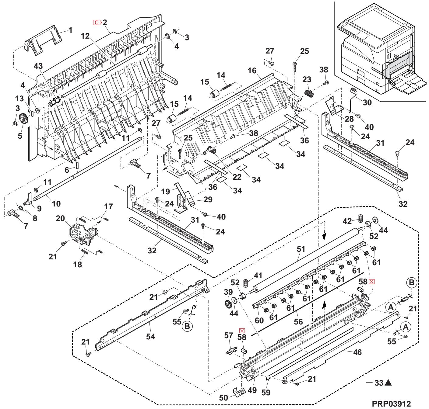
13 ルフ手差しトルはト (Multi manual paper feed tray unit)
| NO. | PARTS CODE | Inter-chang | PRICE RANK | NEW MARK | PART RANK | DESCRIPTION | TR No. | Effective time | |
| Ex. | Ja. | ||||||||
| 1 | PG i DM0 075QSTZ | - | AE | DJ | C | MB side guide F | [Missing parts code] MB パドナト" F | 1st lot | |
| 2 | PG i DM0 076QSTZ | - | AE | DJ | C | MB side guide R | [Missing parts code] MB パドナト" R | 1st lot | |
| 3 | XEBS730P08000 | AC | DD | C | Screw(3×8) | t'λ | |||
| 4 | LSOU-0024QSTE | AS | EQ | D | Manual paper feed tray 1 upper | 手差レット1上 | |||
| 5 | PTME-0271FCZZ | AD | DJ | C | Tray lock pawl | レフロー爪 | |||
| 6 | MSPRC0250QSZZ | AC | DJ | C | Tray lock spring | レフローリフ | |||
| 7 | NGERR0140QSZZ | AD | DJ | C | Width detect rack | 幅検知りは | |||
| 8 | XEPS730P06X00 | AA | DD | C | Screw(3×6X) | t'λ | |||
| 9 | NGERP1385FCZZ | AF | DS | C | Width detect pinion | 幅検知にネト | |||
| 10 | LHLDZ0066QSZZ | AD | DJ | C | Harness holder | ハローマフ- | |||
| 11 | LSOU-0026QSTC | AP | EQ | D | Manual paper feed tray 2 upper | 手差レット2上 | |||
| 12 | QSW-B0017QSZZ | AF | DS | B | Tray detect switch | レフロー爪 | |||
| 13 | DHA i -0359QSZZ | AP | EQ | C | Manual paper feed unit harness | 手差レット一耘 | |||
| 14 | MSPRP2830FCZZ | AA | DJ | C | Width detect plate spring | 幅検知板λ"リフ | |||
| 15 | LPLTP0234QSZZ | AE | DS | C | Width detect plate | 幅検知リフ | |||
| 16 | MLEVP0035QSE2 | AC | DJ | C | Original detect actuator | 原稿検知効工-1-2- | |||
| 17 | CPWBF0106QSE4 | AP | EQ | E | Manual paper feed VR PWB | 手差レVR基板 | |||
| 18 | LSOU-0025QSTC | - | AS | EQ | D | Manual paper feed tray 1 lower | [Missing parts code] 手差レット1下 | 1st lot | |
| 19 | VHPGP1S73P+-18 | AF | DS | B | Photo sensor(GP1S73P) | 手比はさ | |||
| 20 | LSOU-0027QSTC | - | AP | EQ | D | Manual paper feed tray 2 lower | [Missing parts code] 手差レット2下 | 1st lot | |
| 22 | XEBS730P06000 | AA | DD | C | Screw(3×6) | t'λ | |||
| (Unit) | |||||||||
| 901 | CSOU-0024RS65 | BF | GN | E | Manual paper feed tray unit (Except Japan) | 手差レット二耘 | |||
| CSOU-0024RS66 | BF | GN | E | Manual paper feed tray unit (Japan) | 手差レット二耘 | ||||
13 手差手(Multi manual paper feed tray unit)
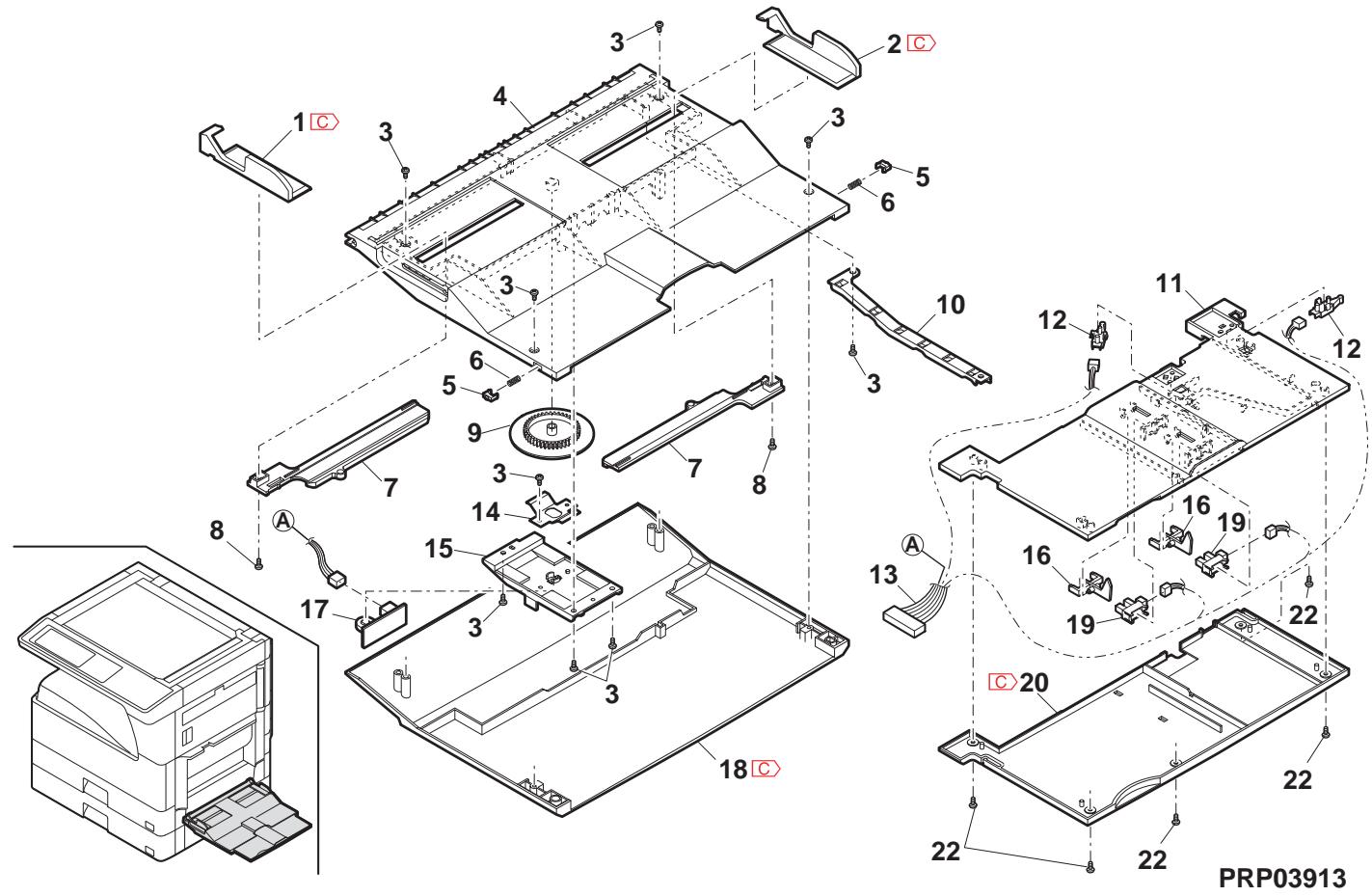
14手差L給紙(Multi manual paper feed unit)
| NO. | PARTS CODE | Inter-chang | PRICE RANK | NEW MARK | PART RANK | DESCRIPTION | TR No. | Effective time | |
| Ex. | Ja. | ||||||||
| 1 | PCOVP 01 07QSTF | AL | EB | D | Multi frame cover N1 | ###-N1 | |||
| 2 | XEBS 30P 10000 | AC | DD | C | Screw(3×10) | ### | |||
| 3 | PSHEZ 0099QSZZ | AC | DJ | C | Protect sheet S | 防振手套S | |||
| 4 | NROLR 0922FCZZ | AR | ZZ | C | Manual paper feed roller | 手差L-1-1- | |||
| 5 | NGERH 0223QSZZ | AC | DJ | C | Gear(20T) | ### | |||
| 6 | XPSSJ 20-07000 | AA | DD | C | Spring pin(φ2-7) | ###-1-1- | |||
| 7 | NGERH 0061QSZZ | AD | DJ | C | Gear(24T) | ### | |||
| 8 | MARP 0009QSZ1 | AF | DS | C | Roller arm | ###-1-1- | |||
| 9 | MSPRT 0351QSZZ | AC | DJ | C | Roller arm spring | ###-1-1-###-1-1-1-1-1-1-1-1-1-1-1-1-1-1-1-1-1-1-1-1-1-1-1-1-1-1-1-1-1-1-1-1-1-1-1-1-1-1-1-1-1-1-1-1-1-1-1-1-1-1- | |||
| 10 | NROLR 1267FCZ1 | AH | DX | C | Pick up roller | 呼达手套 | |||
| 11 | NSFT Z0096QSZ1 | AF | DS | C | Roller shaft F N | ###-1-1-###-1-1-1-1-1-1-1-1-1-1-1-1-1-1-1-1-1-1-1-1-1-1-1-1-1-1-1-1-1-1-1-1-1-1-1-1-1-1-1-1-1-1-1-1-1- | |||
| 12 | XRESP 40-06000 | AA | DD | C | E type ring(E4) | E ### | |||
| 13 | LBSHZ0303FCZZ | AC | DJ | C | M bushing C | M ###-1-1-###-1-1-1-1-1-1-1-1-1-1-1-1-1-1-1-1-1-1-1-1-1-1-1-1-1-1-1-1-1-1-1-1-1-1-1-1-1-1-1-1-1-1-1-1-1-1- | |||
| 14 | LBOSZ0150QSZZ | AE | DS | C | Cam boss A2 N | ###-1-1-###-1-1-1-1-1-1-1-1-1-1-1-1-1-1-1-1-1-1-1-1-1-1-1-1-1-1-1-1-1-1-1-1-1-1-1-1-1-1-1-1-1-1-1-1-1 - | |||
| 15 | MSPRC 1315FCZ1 | AD | DJ | C | Manual paper feed clutch spring A | 手差L-1-1-###-1-1-1-1-1-1-1-1-1-1-1-1-1-1-1-1-1-1-1-1-1-1-1-1-1-1-1-1-1-1-1-1-1-1-1-1-1-1-1-1-1-1-1-1-1-1-2-2-2-2-2-2-2-2-2-2-2-2-2-2-2-2-2-2-2-2-2-2-2-2-2-2-2-2-2-2-2-2-2-2-2-2-2-2-2-2-2-2-2-2-2-2-2-2-2-2- | |||
| 16 | PP i PP 0109FCZ1 | AC | DJ | C | Manual paper feed clutch sleeve A pipe | 手差L-1-1-###-1-1-1-1-1-1-1-1-1-1-1-1-1-1-1-1-1-1-1-1-1-1-1-1-1-1-1-1-1-1-1-1-1-1-1-1-1-1-1-1-1-1-1-1- | |||
| 17 | LBOSZ 0199QSZZ | AE | DS | C | Cam boss A1 | ###-1-1-###-1-1-1-1-1-1-1-1-1-1-1-1-1-1-1-1-1-1-1-1-1-1-1-1-1-1-1-1-1-1-1-1-1-1-1-1-1-1-1-1-1-1-1-1-1-2-2-2-2-3-3-3-3-3-3-3-3-3-3-3-3-3-3-3-3-3-3-3-3-3-3-3-3-3-3-3-3-3-3-3-3-3-3-3-3-3-3-3-3-3-3-3-3-3-3-3-3-3-3- | |||
| 18 | MARP 0041QSZZ | AE | DS | C | Cam transmission arm | ###-1-1-###-1-1-1-1-1-1-1-1-1-1-1-1-1-1-1-1-1-1-1-1-1-1-1-1-1-1-1-1-1-1-1-1-1-1-1-1-1-1-1-1-1-1-1-1-1- | |||
| 19 | MARMP 0006QSZZ | AD | DJ | C | Fulcrum arm | ###-1-1-###-1-1-1-1-1-1-1-1-1-1-1-1-1-1-1-1-1-1-1-1-1-1-1-1-1-1-1-1-1-1-1-1-1-1-1-1-1-1-1-1-1-1-1-1-1 - | |||
| 20 | MSPRD 0347QSZZ | AD | DJ | C | Stopper arm spring | ###-1-1-###-1-1-1-1-1-1-1-1-1-1-1-1-1-1-1-1-1-1-1-1-1-1-1-1-1-1-1-1-1-1-1-1-1-1-1-1-1-1-1-1-1-1-1-1- | |||
| 21 | MCAMP 0003QSZZ | AD | DJ | C | Drive cam | 驱動機 | |||
| 22 | MSPRC 1316FCZ1 | AE | DS | C | Manual paper feed clutch spring B | 手差L-1-1-###-1-1-1-1-1-1-1-1-1-1-1-1-1-1-1-1-1-1-1-1-1-1-1-1-1-1-1-1-1-1-1-1-1-1-1-1-1-1-1-1-1-1-1-1-2-2-2-2-2-3-3-3-3-3-3-3-3-3-3-3-3-3-3-3-3-3-3-3-3-3-3-3-3-3-3-3-3-3-3-3-3-3-3-3-3-3-3-3-3-3-3-3-3-3- | |||
| 23 | PP PP 0004QSZZ | AC | DJ | C | Manual paper feed pawl A | 手差L-1-1-###-1-1-1-1-1-1-1-1-1-1-1-1-1-1-1-1-1-1-1-1-1-1-1-1-1-1-1-1-1-1-1-1-1-1-1-1-1-1-1-1-1-1-1-1 - | |||
| 24 | MSPRC 2175FCZZ | AA | DD | C | Pawl A spring | 爪A##T##T | |||
| 25 | NSFT Z0017QSP 1 | AD | DJ | C | Manual paper feed cum shaft | 手差L##T##T | |||
| 26 | NGERH 0972FCZZ | AB | DJ | C | Gear(27T) | ### | |||
| 27 | CPLTM 0345QS0 1 | AG | DX | C | Paper feed connect plate TLPD | 絵紙接縄板TLPD | |||
| 28 | XEBS 730P08000 | AC | DD | C | Screw(3×8) | ### | |||
| 29 | PTME 0178FCZ1 | AC | DJ | C | Manual paper feed pawl A | 手差L##T##T | |||
| 30 | MSPRC 2175FCZZ | AA | DD | C | Pawl A spring | 爪A##T##T | |||
| 31 | RPLU 0028QSZZ | AM | EG | B | Multi field solenoid | ### | |||
| 32 | RPLU 0028QSPZ | 1 | AM | EG | B | Multi field solenoid | ### | ||
| 33 | MSPRC 318FCZ1 | AA | DJ | C | Manual paper feed spring B | 手差L##T##T B | |||
| 34 | PTME 0179FCZ | AC | DD | C | Manual paper feed pawl B | 手差L##T##T B | |||
| 35 | XBBS 730P01000 | AA | DD | C | Screw(3×10) | ### | |||
| 36 | MARP 0027QSZ | AE | DJ | C | Manual paper feed tray arm | 手差L##T##T A | |||
| 37 | LFRM 0048QSTH | AS | EQ | D | Multi frame | ### | |||
| 38 | MARP 008QSZZ | AH | DX | C | Stopper arm | ### | |||
| 39 | LPLTP 0056QSZ3 | AD | DJ | C | Stopper plate | ### | |||
| 40 | XEPS 730P06X00 | AA | DD | C | Screw(3×6X) | ### | |||
| 41 | XEBS 730P08000 | AC | DD | C | Screw(3×10) | ### | |||
| 42 | PSHEZ 0241QSZZ | AB | DJ | C | Manual paper feed protection sheet | 手差L##T##T B | |||
| 43 | LBNDJ 0013FCZ1 | AE | DJ | C | Band | 结束### | |||
| 44 | NSFT Z0090QSZZ | AG | DX | C | Roller shaft R N | ### | |||
| 45 | MSPRD 0302QSZZ | AC | DJ | C | Manual paper feed coupling spring | 手差L##T##T ### | |||
| 46 | MSPRD 0329QSZZ | AC | DJ | C | Revers ACT spring | 反転ACT | |||
| 47 | NCPL 0022QSZZ | AD | DJ | C | Manual paper feed coupling | 手差L##T##T ### | |||
| 48 | CPWBF 0083QSE5 | AU | EZ | E | Sensor PWVB | ### | |||
| 49 | DHA i 0360QSPZ | AE | DJ | C | DUP 2 sensor harness | DUP 2 ### | |||
| 50 | MLEVP 0104QSZZ | AD | DJ | C | Revers lever | 反転### | |||
| 51 | LBSHZ0006QSZZ | AC | DJ | C | M bushing 2 | M ### | |||
| 52 | LSTPP 0011QSZZ | AC | DJ | C | Resin E type ring | 树脂 E ### | |||
| 53 | LX-WZ0011QSZZ | AB | DD | C | Poly slider(5-12-0.5) | ### | |||
| (Unit) | |||||||||
| 901 | CFRM 0048RS 55 | BE | GN | E | Multi manual paper feed unit(Without No.36,40,41,43) | ### | |||
14手差L給紙(Multi manual paper feed unit)
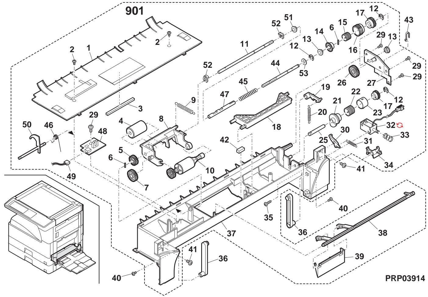
15 DV 1=yt (DV unit)
| NO. | PARTS CODE | Inter-changese | PRICE RANK | NEW MARK | PART RANK | DESCRIPTION | TR No. | Effective time | |
| Ex. | Ja. | ||||||||
| 1 | LHLDZ0142QSZZ | AD | DJ | C | Filter holder\( \text{ ナリバ}-\text{ イフ }^{\prime\prime} \) - | ||||
| 2 | PF i LD0313FCZZ | AG | DX | A | TN filter | TN 751- | |||
| 3 | XEBS730P08000 | AC | DD | C | Screw(3×8) | \( t^*λ \) | |||
| 4 | PG i DM0158QSZZ | AH | DX | C | Cartridge guide top | 加一 ナリバが応上 | |||
| 5 | PSEL-0162QSZZ | AE | DJ | A | DV blade | DV 751- | |||
| 6 | LX-BZ1066FCZZ | AC | DD | C | Blue screw(3×6) | 青さλ | |||
| 7 | PG i DM0159QSZZ | AM | EG | C | Cartridge guide bottom | 加一 ナリバが応下 | |||
| 8 | PMLT-0137QSZZ | - | AD | DJ | C | Pipe cushion N | [Missing parts code] \( \text{ ナリバ} \) #N | ||
| 9 | PMLT-0142QSZZ | AC | DJ | C | Pipe cover cushion N | \( \text{ ナリバ} \) #'加一 #E#N | |||
| 10 | PSEL-0964FCZ1 | AA | DJ | C | Cover upper seal | 加一 上ごル | |||
| 11 | PMLT-0141QSZZ | AC | DJ | C | DV guide cushion N | DV 方応 #E#N | |||
| 12 | PMLT-0147QSZZ | AB | DJ | C | DV side cushion R | DV 751- #E#R | |||
| 13 | LDA i U0033QSZZ | AC | DJ | C | DV block R | DV 751- R | |||
| 14 | NROLP0150QSZZ | AS | EQ | C | MX roller L | MX 751-L | |||
| 15 | NROLP0149QSZZ | AS | EQ | C | MX roller R | MX 751-R | |||
| 16 | PMLT-0146QSZZ | AB | DJ | C | DV side cushion F | DV 751- #E#F | |||
| 17 | XEBS730P06000 | AA | DD | C | Screw(3×6) | \( t^*λ \) | |||
| 18 | LHLDZ0132QSZ1 | AC | DJ | C | Scraper holder | \( 斯ルーニ"-都" - | |||
| 19 | PBOX-0025QSZZ | AM | EG | C | DV BOX | DV 751- | |||
| 20 | DHA i 0566QSPZ | AQ | EQ | C | Toner sensor harness | トーキングー・スス | |||
| 21 | XRESP40-06000 | AA | DD | C | E ring(E4) | E 150° | |||
| 22 | NBRGY0769FCZ2 | AQ | EB | C | MG bearing | MG 751- | |||
| 23 | NPLYZ0041QSZZ | AC | DJ | C | MX puley | MX 751- | |||
| 24 | LPLT0194QSZZ | AC | DJ | C | DV box fixing plate | 現像槽固定板 | |||
| 25 | XBPSS730P06KS0 | AB | DD | C | Screw(3×6KS) | \( t^*λ \) | |||
| 26 | NPLYZ0040QSZZ | AC | DJ | C | MG puley | MG 751- | |||
| 27 | NBLTH0494FCZZ | AD | DJ | B | DV belt | DV 751- | |||
| 28 | PSHEZ0652QSZZ | AA | DJ | A | DV side sheet F | DV 751- #E#F | |||
| 29 | XBBSS730P04000 | AA | DD | C | Screw(3×4) | \( t^*λ \) | |||
| 30 | PSHEZ0651QSZZ | AA | DJ | A | DV side sheet R | DV 751- #E#R | |||
| 31 | XRESP50-06000 | AA | DD | C | E ring(E5) | E 150° | |||
| 32 | XEBS730P10000 | AC | DD | C | Screw(3×10) | \( t^*λ \) | |||
| 33 | NBRGC0020QSZZ | AH | DD | C | DMX bearing(F6/14) | DMX 751- #E#F | |||
| 34 | NGERH1653FCZZ | AC | DJ | C | DMX gear(24T) | DMX 751- | |||
| 35 | LX-BZ1143FCPZ | AD | DJ | C | Screw | \( t^*λ \) | |||
| 36 | LHLDZ0128QSZZ | AC | DJ | C | DV holder F | DV 751- F | |||
| 37 | MSPRD0395QSZZ | AC | DJ | C | Bias spring | \( n^*15λ \) | |||
| 38 | LHLDZ0129QSZZ | AC | DJ | C | MG holder | MG 751- | |||
| 39 | PCOVP0122QSZZ | AF | DS | D | DV cover F | DV 加一 F | |||
| 40 | NROLM0151QSZZ | - | BT | NE | C | MG roller | [Missing parts code] MG 751- | ||
| 41 | PMLT-0002YSZ1 | AC | DJ | C | DV TH cushion | DVTH 751- | |||
| 42 | PSHEP0632QSZZ | AB | DJ | C | Doctor cover seal | \( トカーネー - // - // - \) | |||
| 43 | LPLTMO002YSZ4 | AR | EQ | C | Doctor reinforce plate | \( t^*4 -補強板 \) | |||
| 44 | LPLTMO477QSZZ | AK | EB | C | DV doctor | DV 751- | |||
| 45 | XBPBZ30P03000 | AB | DD | C | Screw(3×3) | \( t^*λ \) | |||
| 46 | PCOVP0121QSZZ | AE | DJ | C | Doctor cover | \( t^*4 -補+ - \) | |||
| PCOVP0121QSZ1 | 1 | AE | DJ | C | Doctor cover | \( t^*4 -補+ - \) | |||
| 47 | XBBBZ30P06000 | AC | DD | C | Screw(3×6) | \( t^*λ \) | |||
| 48 | RDTCM0021QSZZ | AY | FQ | B | ATC sensor | ATC 751- | |||
| 49 | XUBUZ30P08000 | AA | DD | C | Screw(3×8) | \( t^*λ \) | |||
| 501 | CHLDZ0142RS51 | - | AN | EG | E | Filter holder unit | [Missing parts code] \( \text{ ナリバ} \) - #E#R | ||
| (Unit) | |||||||||
| 901 | DUNT-0777RSZZ | BN | HZ | E | DV unit | DV 751- | |||
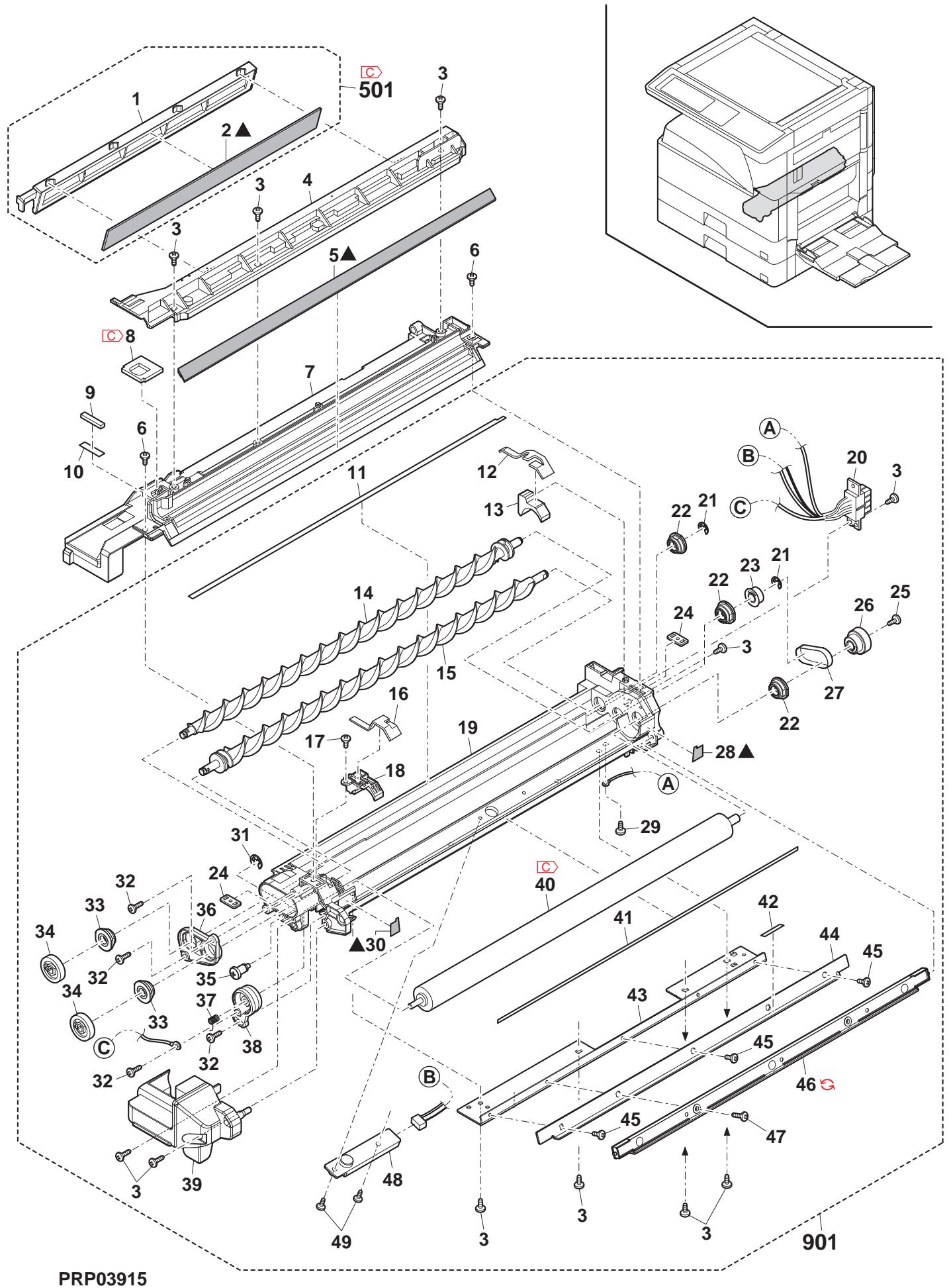
16 7.(Process unit)
| NO. | PARTS CODE | Inter-chang | PRICE RANK | NEW MARK | PART RANK | DESCRIPTION | TR No. | Effective time | |
| Ex. | Ja. | ||||||||
| 1 | XEBS730P08000 | AC | DD | C | Screw(3×8) | £'s | |||
| 2 | PCAPH0022QSZZ | AC | DJ | D | Toner pipe cap | 扑-ハ" ナマリフ" | |||
| 3 | NSRW-0002QSZZ | AE | DS | C | Transport pipe screw | 搬送ハ" ナマリフ" | |||
| 4 | LPLTM0241QSZZ | AF | DS | C | Process reinforce plate | 7" 口ス補強板 | |||
| 5 | MLEVP0065QSZZ | AE | DS | C | Separator pawl lever | 剥離爪い" | |||
| 6 | CFRM-0049RS76 | - | AZ | FQ | A | Process frame unit [Missing parts code] | [Missing parts code] | 1st lot | |
| 7 | NCPL-0003QSZ1 | AC | DJ | C | Screw coupling | クルーハーフ" ナマリフ" | |||
| 10 | PSEL-0071QSZZ | AF | DS | A | Seal R | はさR | |||
| 11 | PSEL-0070QSZZ | AF | DS | A | Seal F | はさF | |||
| 12 | PSHT-0014QSZZ | AC | DJ | C | Toner pipe shutter | 扑-ハ" ナマリフ" | |||
| 13 | PP I PP0017QSZZ | AE | DS | C | Toner pipe | 扑-ハ" ナマリフ" | |||
| 14 | MSPRC0045QSZ1 | AC | DJ | C | Toner pipe spring | 扑-ハ" ナマリフ" | |||
| 15 | PSPAZ0696FCZZ | AC | DJ | C | Pipe cap spacer | [able] | |||
| 16 | NGERH0036QSZZ | AC | DJ | C | Transport screw gear(30T) | 搬送ハリス-ささ | |||
| 17 | PCOV0132QSZZ | AF | DS | D | Drum cover | [able] | |||
| 18 | NGERH0039QSZZ | AE | DS | C | Transport pipe gear(14T) | 搬送ハリス-ささ | |||
| 19 | LFIX-0015QSZZ | AE | DJ | C | Drum fixing plate B (Inch series,AB Series agency) | [able] 固定板 B | |||
| LFIX-0014QSZZ | AE | DJ | C | Drum fixing plate A (Except Inch series,AB Series agency) | [able] 固定板 A | ||||
| 20 | NGERH0037QSZZ | AC | DJ | C | Idle gear(26T) | [able] | |||
| 21 | NGERH0038QSZZ | AC | DJ | C | Transport pipe gear(15T) | 搬送ハリス-ささ | |||
| 22 | NSFTZ0020QSZ1 | AL | DS | C | Transport screw | 搬送ハリス- | |||
| 23 | NBRGP0299FCPZ | AD | DJ | C | DV bearing | DV 軸受 | |||
| 24 | PMLT-0018QSZ1 | AC | DJ | C | Transport screw cushion | 搬送ハリス-モト | |||
| 25 | PTME-0021QSZZ | AK | DX | C | Separator pawl | 剥離爪 | |||
| 26 | LX-WZ0329FCPZ | AB | DD | C | Washer | [able] | |||
| 27 | LX-RZ0001QSZZ | AB | DD | C | Star ring | [able] | |||
| 28 | MSPRT0214QSZZ | AB | DJ | C | Lever spring | [able] | |||
| 29 | LX-BZ0064QSZZ | AA | DD | C | Screw(3×8) | [able] | |||
| 30 | MSPRC0213QSZZ | AB | DJ | C | Separator pawl spring | 剥離爪[able] | |||
| 31 | CHLDZ0035RS58 | - | AW | FG | A | MC holder unit [Missing parts code] | MC ナマリフ" ナマリフ" | 1st lot | |
| 32 | CCLEZ0011QS32 | BD | GN | A | Cleaning brade | [able] | |||
| UCLEZ0011QSZ1 | - | BR | MJ | A | Cleaning blade [Missing parts code] | [able] | |||
| 33 | XEBS730P10000 | AC | DD | C | Screw(3×10) | [able] | |||
| 34 | PSHEZ0329QSZZ | AC | DJ | C | Toner stir sheet | 扑-攤拌ト | |||
| 35 | PTPE-0026QSZ1 | AA | DJ | C | Screw tape | クルーハーフ" | |||
| 36 | LHLDZ0090QSZZ | AC | DJ | C | Star ring holder | 扑-ハ" ナマリフ" | |||
| 37 | LX-BZ0406FCPZ | AA | DD | C | Screw(3×4) | [able] | |||
| 38 | PRNGF0106FCZ2 | AC | DJ | A | Star ring N2 | [able] | |||
| 39 | PRNGP0081FCZ1 | AB | DJ | C | Resin E ring(E4) | 樹脂 E ナマリフ" | |||
| 40 | PSEZ0557QSZZ | AC | DJ | C | DR brake sheet | DR ナマリフ" | |||
| 41 | XBBS730P06000 | AC | DD | C | Screw(3×6) | [able] | |||
| 501 | CP i PP0017RS51 | - | AN | EG | E | Toner pipe unit [Missing parts code] | 扑-ハ" ナマリフ" | ||
| 502 | CTME-0021RS51 | AK | EB | A | Separator pawl unit | 剥離爪上部 | |||
| (Unit) | |||||||||
| 901 | CFRM-0049RS5N | BG | GT | E | Process unit(Without No.19,44) | [able] | |||
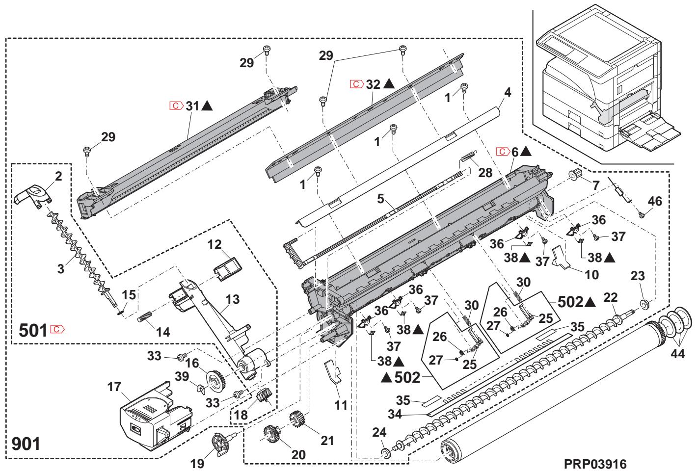
17 定着1(Fusing unit 1)
| NO. | PARTS CODE | Inter-chang | PRICE RANK | NEW MARK | PART RANK | DESCRIPTION | TR No. | Effective time | |
| Ex. | Ja. | ||||||||
| 1 | MARP0 048QSZ2 | - | AF | DS | C | Pressure release fulcrum arm [Missing parts code] 压解支点7-4 | 1st lot | ||
| 2 | MLEVP0 100QSZZ | AE | DS | C | Pressure release lever F TL 压解1' - F TL | ||||
| 3 | MLEVP0 101QSZZ | AE | DS | C | Pressure release lever R TL 压解1' - R TL | ||||
| 8 | RTHM-0050FCZZ | AN | EG | B | Thermostat TL - ヤーマスリフ | ||||
| 10 | DHA i - 0367QSPZ | AE | DJ | C | DUP sensor harness DUP ヤーマスリフ | ||||
| 11 | LHLDW008QSZZ | AB | DJ | C | Harness ring - ヤーマスリフ | ||||
| 12 | RH-HX0001QSLB | AT | EZ | B | Thermistor TL - ヤーマスリフ | ||||
| 13 | LPLTM0338QSZ1 | AC | DJ | C | Fusing earth plate UR 定着7-板 UR | ||||
| 14 | VHPGP1SQ73P-18 | AF | DS | B | Photo sensor(GP1SQ73P) トトデー | ||||
| 15 | XEBS730P06000 | AA | DD | C | Screw(3×6) - λ | ||||
| XEBS730P06000 | - | AA | DD | C | Screw(3×6) [To No.51] - λ (3×6) | 09/07 mid | |||
| 18 | LSTPF0172FCZZ | AA | DD | C | Roller stopper - ヤーマスリフ - | ||||
| 19 | RLMPU0040QSPZ | BA | FX | B | Heater lamp (120V) - ヤーマスリフ | ||||
| RLMPU0041QSPZ | BA | FX | B | Heater lamp (230V) - ヤーマスリフ | |||||
| RLMPU0039QSPZ | BA | FX | B | Heater lamp (100V) - ヤーマスリフ | |||||
| 22 | LHLDZ0139QSZZ | AD | DJ | C | Lamp fixing plate - ヤーマスリフ 取付板 | ||||
| 23 | LFRM-0098QSZZ | AV | FG | D | Fusing upper frame(TL) 定着上7-板 | ||||
| 24 | MSPRC0323QSZZ | AC | DJ | C | Fusing unit earth spring - ヤーマスリフ | ||||
| 25 | LPLTM0337QSZ1 | AC | DJ | C | Fusing earth plate UF 定着7-板 UF | ||||
| 27 | NROLM0129QSZZ | BB | FX | A | Heat roller(TL) - ヤーマスリフ | ||||
| 28 | NGERH0171QSZZ | AR | EQ | A | Fusing gear(TL)(38T) 定着7- | ||||
| 29 | NBRGP0025QSZZ | AN | EQ | A | Upper HR bearing(TL) 上HR 軸受 | ||||
| 30 | LPLTM0343QSZZ | AB | DJ | C | Gear key plate(TL) - ヤーマスリフ | ||||
| 31 | CPLTM0336QS02 | AR | EQ | A | Fusing cleaner plate 定着7-板 | ||||
| 32 | MSPRT0257QSZ1 | AC | DJ | C | Upper paw spring 上爪7-ロルフ | ||||
| 33 | MSPRD0322QSZZ | AC | DJ | C | Fusing ACT return spring 定着ACT 復歸7-ロルフ | ||||
| 34 | MLEVP0099QSZ1 | AF | DS | C | Fusing rear paper detect lever 定着後用紙 换知1- | ||||
| 35 | PGiDM0113QSZZ | AT | EZ | C | Fusing rear upper guide 定着後上PG | ||||
| 36 | PTME-0282FCZZ | AH | DX | A | Upper separate pawl 上剥離爪 | ||||
| 37 | LX-WZ0006QSZZ | AC | DD | C | Washer 刺雕爪WNT | ||||
| 38 | PTME-0024QSZ | AN | EQ | A | Upper separate pawl 上剥離爪LPD | ||||
| 39 | LX-BZ0086QSPZ | AD | DJ | C | Fusing unit fixing screw 定着7-板 取付比 | ||||
| 40 | CPLTM0513QS01 | - | AF | DS | A | Thermistor felt fixing plate [Missing parts code] - ヤーマスリフ 取付板 | 1st lot | ||
| 41 | LX-BZ1195FCZZ | AC | DD | C | Screw(M3) - λ | ||||
| 42 | LSTYM0004QSZZ | AK | DX | C | Fusing upper frame stay And3 定着上7-板 And3 | ||||
| 43 | LPLTM0510QSZZ | AD | DJ | C | Earth joint plate -λ連結板 | ||||
| 44 | LX-BZ1181FCZZ | AB | DD | C | Screw(3×6) - λ | ||||
| 45 | LPLTM0473QSZZ | AE | DJ | C | Fusing earth plate And3 定着7-板 And3 | ||||
| 46 | LX-BZ1126FCPZ | AB | DD | C | Thermister screw - ヤーマスリフ - λ | ||||
| 47 | XHPS730P04000 | AB | DD | C | Screw(3×4) - λ | ||||
| 48 | XWHS730-05080 | AA | DD | C | Washer - ヤーマスリフ | ||||
| 49 | LX-BZ0093QSZZ | AC | DD | C | Screw - λ | ||||
| 50 | PCOVP0148QSZZ | AK | DX | C | Thermostat cover - ヤーマスリフ 加- | ||||
| 51 | NXBBS730P06000 | - | AC | DD | C | Screw(3×4) [From No.15] - λ (3×4) | 1st lot | ||
| (Unit) | |||||||||
| 901 | DUNTW0782RSZZ | BW | RJ | E | Fusing unit(Include Block 18) (120V) 定着7-板 (7"ロル18含む) | ||||
| DUNTW0782RS12 | BW | RJ | E | Fusing unit(Include Block 18) (230V) 定着7-板 (7"ロル18含む) | |||||
| DUNTW0782RS11 | BW | RJ | E | Fusing unit(Include Block 18) (100V) 定着7-板 (7"ロル18含む) | |||||
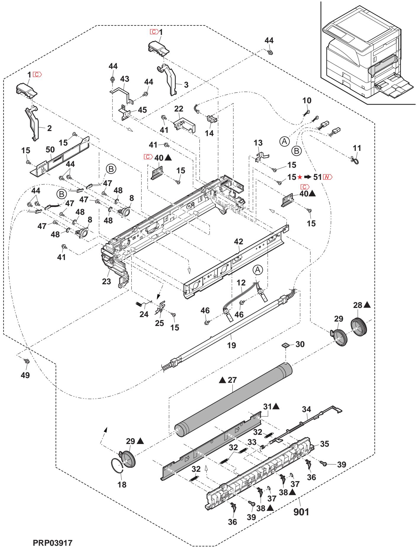
18 定着1=2(Fusing unit 2)
| NO. | PARTS CODE | Inter-changese | PRICE RANK | NEW MARK | PART RANK | DESCRIPTION | TR No. | Effective time | |
| Ex. | Ja. | ||||||||
| 1 | NBRGY 0 0 2 QSZZ | AL | EB | A | Fusing pressure bearing FU 加压軸受 | ||||
| 2 | NROLR 0 1 5 6 QSZZ | BF | GN | A | Fusing roller 压着ローナ | ||||
| 3 | MSPRC 0 3 2 4 QSZZ | AC | DJ | C | Fusing pressure spring(TL) 定着加压 ムリウ | ||||
| 5 | LPL TM 0 3 4 1 QSZ1 | AC | DJ | C | Fusing earth plate(DR) 定着7-8板 | ||||
| 7 | LPL TM 0 5 3 1 QSZZ | - | AC | DJ | C | High resistor earth plate And3 [Missing parts code] [Missing parts code] And3 | 1st lot | ||
| 8 | PG i DH 0 1 4 0 QSZZ | AY | FQ | A | Fusing front guide 定着前がト | ||||
| 9 | LPL TM 0 3 4 0 QSZZ | AC | DJ | C | Fusing earth plate(DF) 定着7-8板 | ||||
| 11 | MSPRD 0 3 2 8 QSZ1 | AC | DJ | C | Lower pawl spring(RTL) 下爪7-8R | ||||
| 12 | PTME-0 0 4 1 QSZZ | AG | DS | A | Lower separate pawl 下剥離爪 | ||||
| 13 | TCAUH 0 0 1 7 QSZ1 | AC | DJ | D | High temperature caution label (Except Japan) 高温注意は% | ||||
| TLABH 0 3 8 1 QSZZ | AE | DJ | D | High temperature caution label (Japan) 高温注意は% | |||||
| 14 | XBPSN 3 0 0 8 KS0 | AA | DD | C | Screw(3×8KS) ムλ | ||||
| 15 | MSPRD 0 3 2 7 QSZ1 | AC | DJ | C | Lower pawl spring F(TL) 下爪7-8R F | ||||
| 16 | LFRM-0 0 7 2 QSZ5 | - | AT | EQ | D | Fusing lower frame [Missing parts code] 定着下ルス | 1st lot | ||
| 17 | MSPRD 0 3 2 6 QSZZ | AC | DJ | C | Fusing rear lower guide spring 定着後下が [復鳬7-8R] | ||||
| 18 | PG i DM 0 1 1 5 QSZZ | AS | EQ | C | Fusing rear lower guide 定着後下が [復鳬7-8R] | ||||
| 19 | TLABH 0 2 8 9 QSZZ | AA | DJ | D | Fusing green label 定着7-8R [Except Japan] 高温注意は% | ||||
| 20 | MLEVF 0 1 1 1 QSZZ | AD | DJ | C | Pressure lever F(AND2) 加压レフ - F | ||||
| 21 | MLEVF 0 1 1 2 QSZZ | AD | DJ | C | Pressure lever R(AND2) 加压レフ - R | ||||
| 22 | TLABH 0 6 8 5 QSZZ | AD | DJ | D | High temperature caution label (Except Japan) 高温注意は% | ||||
| TLABH 0 6 8 3 QSZZ | AE | DJ | D | High temperature caution label (Japan) 高温注意は% | |||||
| 23 | VRH- ST 2 HB 5 0 7 K | - | AD | DJ | C | Resistor(500MΩ) [Missing parts code] 担抗 (500MΩ) | 09/07 mid | ||
| 24 | XWHS 7 4 0-0 8 0 9 0 | AA | DD | C | Washer ムツロー | ||||
| (Unit) | |||||||||
| 901 | DUNTW 0 7 8 2 RSZZ | BW | RJ | E | Fusing unit(Include Block 17) (120V) 定着7-8R (7-8R) 17 含む) | ||||
| DUNTW 0 7 8 2 RS 1 2 | BW | RJ | E | Fusing unit(Include Block 17) (230V) 定着7-8R (7-8R) 17 含む) | |||||
| DUNTW 0 7 8 2 RS 1 1 | BW | RJ | E | Fusing unit(Include Block 17) (100V) 定着7-8R (7-8R) 17 含む) | |||||
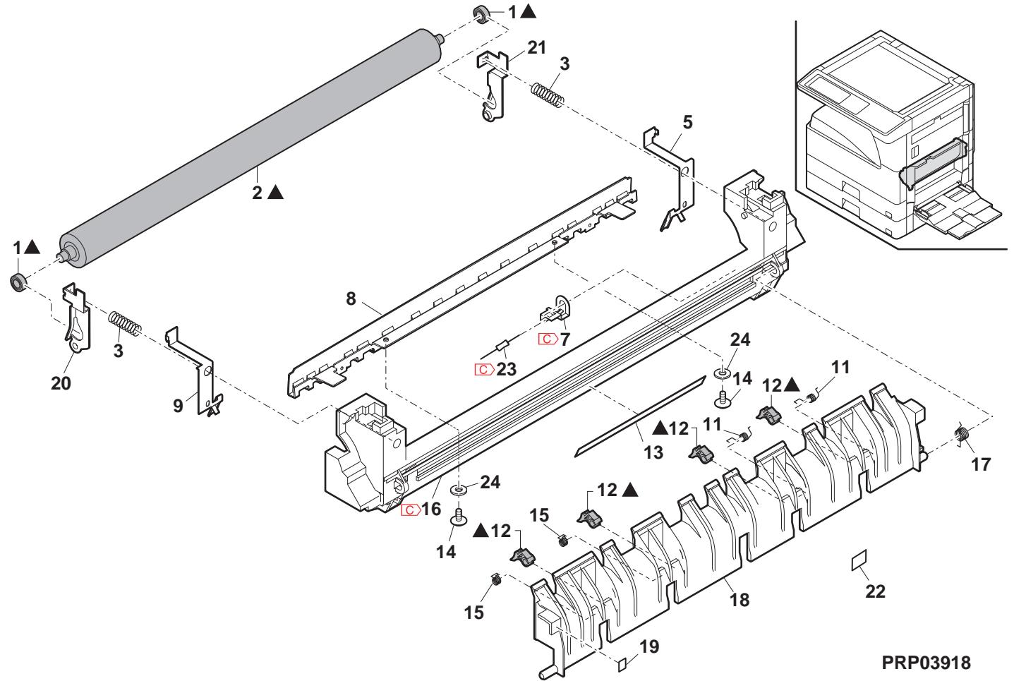
19 駆動部 (Drive unit)
| NO. | PARTS CODE | Inter-changec | PRICE RANK | NEW MARK | PART RANK | DESCRIPTION | TR No. | Effective time | |||||||||||||||||||
| Ex. | Ja. | ||||||||||||||||||||||||||
| 1 | XBP S7 40 P08ES0 | AB | DD | C | Screw(4×8ES) | b'λ | |||||||||||||||||||||
| 2 | RMOTP 0069QSPZ | BA | FX | B | Main motor | m'v-à-à- | |||||||||||||||||||||
| 3 | CPLTM0160QS02 | AU | FG | C | Main drive plate | m'v-à-à-à-à- | |||||||||||||||||||||
| 4 | MSPRC0200QSZ1 | AB | DJ | C | Ratchet spring | f'v'v'v'v'v'v'v'v'v'v'v'v'v'v'v'v'v'v'v'v'v'v'v'v'v'v'v'v'v'v'v'v'v'v'v'v'v'v'v'v'v'v'v'v'v'v'v'v'v'v' v'v'v'v'v'v'v'v'v'v'v'v'v'v'v'v'v'v'v'v'v'v'v'v'v'v'v'v'v'v'v'v'v'v'v'v'v'v'v'v'v'v'v'v'v'v'v'v'v'v' | |||||||||||||||||||||
| 5 | NGERH0234QSZZ | AF | DS | C | Ratchet gear(49T) | f'v'v'v'v'v'v'v'v'v'v'v'v'v'v'v'v'v'v'v'v'v'v'v'v'v'v'v'v'v'v'v'v'v'v'v'v'v'v'v'v'v'v'v'v'v'v'v'v' v' | |||||||||||||||||||||
| 6 | NGERH0090QSZ1 | AF | DS | C | Fusing drive gear(19T) | 定着驱动" | |||||||||||||||||||||
| 7 | NGERH0084QSZZ | AK | DX | C | Gear(94/21T) | ||||||||||||||||||||||
| 8 | XRESP70-08000 | AA | DD | C | E type ring(E7) | E'v'v'v'v'v'v'v'v'v'v'v'v'v'v'v'v'v'v'v'v'v'v'v'v'v'v'v'v'v'v'v'v'v'v'v'v'v'v'v'v'v'v'v'v'v'v'v'v'v' | |||||||||||||||||||||
| 9 | NGERH0192QSZZ | AD | DJ | C | Gear(46/19T) | ||||||||||||||||||||||
| 10 | NGERH0086QSZZ | AD | DJ | C | Gear(39/21T) | [MX-M260/M260N/M260FP/M260FG, AR-5726] | |||||||||||||||||||||
| NGERH0190QSZZ | AC | DJ | C | Gear(39/19T) | [MX-M310/M310N/M310FP/M310FG, AR-5731] | ||||||||||||||||||||||
| 11 | NGERH0087QSZZ | AE | DJ | C | Gear(30/21T) | [MX-M260/M260N/M260FP/M260FG, AR-5726] | |||||||||||||||||||||
| NGERH0189QSZZ | AD | DJ | C | Gear(30/21T) | [MX-M310/M310N/M310FP/M310FG, AR-5731] | ||||||||||||||||||||||
| 12 | NGERH0010QSZZ | AD | DJ | C | Gear(28T) | ||||||||||||||||||||||
| 13 | NGERH0092QSZZ | AD | DJ | C | Gear(30/16T) | ||||||||||||||||||||||
| 14 | NGERH0093QSZZ | AD | DJ | C | Gear(28/16T) | ||||||||||||||||||||||
| 15 | XBPS730P06KS0 | AB | DD | C | Screw(3×6KS) | ||||||||||||||||||||||
| 16 | NGERH0095QSZZ | AE | DJ | C | Gear | ||||||||||||||||||||||
| 17 | NGERH0191QSZZ | AC | DJ | C | MG gear | MG "v" | |||||||||||||||||||||
| 18 | NGERH0186QSZZ | AH | DX | C | N gear(58/21T) | N "v" | |||||||||||||||||||||
| 19 | NGERH0096QSZZ | AE | DJ | C | Gear(37/25T) | ||||||||||||||||||||||
| 20 | CPLTM0161QS02 | AP | EQ | C | Sub drive plate | g'v'v'v'v'v'v'v'v'v'v'v'v'v'v'v'v'v'v'v'v'v'v'v'v'v'v'v'v'v'v'v'v'v'v'v'v'v'v'v'v'v'v'v'v'v'v'v'v'v'V | |||||||||||||||||||||
| 21 | MSPRC0262QSZ1 | AC | DJ | C | MG spring | MG λ" 'v' v'v'v'v'v'v'v'v'v'v'v'v'v'v'v'v'v'v'v'v'v'v'v'v'v'v'v'v'v'v'v'v'v'v'v'v'v'v'v'v'v'v'v'v'v'v'v'v'v" | |||||||||||||||||||||
| 22 | NCPL-0009QSZZ | AC | DJ | C | MG coupling | MG 加" 'v' " " " " " " " " " " " " " " " " " " " " " " " " " " " " " " " " " " " " " " " " " " " " " " " " " " " " " " " " " " " " " " " " " " " " " " " " " " " " " " " " " " " " " " " " " " " " " " " " " " " " “ | |||||||||||||||||||||
| 23 | NGERH0091QSZZ | AE | DJ | C | Coupling gear(34T) | 加" 'v' " " " " " " " " " " " " " " " " " " " " " " " " " " " " " " " " " " " " " " " " " " " " " " " " " " " " " " " " " " " " " " " " " " " " " " " " " " " " " " " " " " " " " " " " " " " " " " " | 24 | CGERH0204RS51 | AX | FQ | C | Drum coup gear | d" v' v' v' v' v' v' v' v' v' v' v' v' v' v' v' v' v' v' v' v' v' v' v' v' v' v' v' v' v' v' v' v' v' v' v' v' v' v' v' v' v' v' v' v' v' v' v' v' v' v' v" | ||||||||||||||
| 25 | DHA i -0602QSPZ | AE | DS | C | AN2R main motor harness | AN2R main motor harness | |||||||||||||||||||||
| 26 | LX-WZ0012QSZZ | AB | DD | C | Poly slider AND2 | 木" 'v' " " " " " " " " " " " " " " " " " " " " " " " " " " " " " " " " " " " " " " " " " " " " " " " " " " " " " " " " " " " " " " " " " " " " " | 27 | XRESP50-06000 | AA | DD | C | E type ring(E5) | E 'v' v'v'v'v'v'v'v'v'v'v'v'v'v'v'v'v'v'v'v'v'v'v'v'v'v'v'v'v'v'v'v'v'v'v'v'v'v'v'v'v'v'v'v'v'v'v'v'v' v' | ||||||||||||||
| 28 | LX-WZ0476FCZZ | AC | DD | C | Poly slider | 木" 'v' " " " " " " " " " " " " " " " " " " " " " " " " " " " " " " " " " " " " " " " " " " " " " | 29 | LX-WZ0407FCZZ | AB | DD | C | Poly slider | 木" 'v' " " " " " " " " " " " " " " " " " " " " " " " " " " " " | 2 | (Unit) | ||||||||||||
| 301 | CPLTM0160RS59 | BH | HC | E | Drive unit [MX-M260/M260N/M260FP/M260FG, AR-5726] 驱動ルト | ||||||||||||||||||||||
| CPLTM0160RS60 | BH | HC | E | Drive unit [MX-M310/M310N/M310FP/M310FG, AR-5731] 驱動ルト | |||||||||||||||||||||||
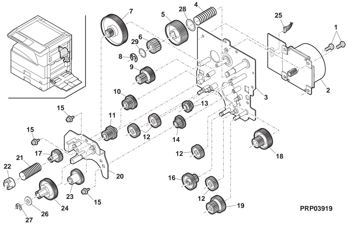
20 第一排紙1 (1st delivery paper unit 1)
| NO. | PARTS CODE | Inter-chang | PRICE RANK | NEW MARK | PART RANK | DESCRIPTION | TR No. | Effective time | ||
| Ex. | Ja. | |||||||||
| 1 | NSFTZ0042QSZ1 | AE | DS | C | Delivery sub roller shaft | 排紙從動-フ軸 | ||||
| 3 | NROLP0049QSZZ | AC | DJ | C | Delivery sub roller | 排紙從動-フ軸 | ||||
| 4 | NROLP0111QSZZ | AD | DJ | C | Delivery sub roller(Large) | 排紙從動-フ軸(大) | ||||
| 6 | PBRSR0019QSZZ | AK | DX | B | Discharger brush LP | 除電フローリVP | ||||
| 7 | NROLR0114QSZZ | AR | EZ | C | Delivery roller C | 排紙-フ-CP | ||||
| 8 | NBRGY2122SCZZ | AB | DD | C | Transport roller bearing | 搬送-フ-軸受 | ||||
| 9 | LPLTM0195QSZZ | AC | DJ | C | Delivery earth plate A | 排紙-フ-板A | ||||
| 10 | NBRGM0501FCZZ | AB | DJ | C | Bearing | 軸受 | ||||
| 11 | XRESP50-06000 | AA | DD | C | E type ring(E5) | E リフ | ||||
| 12 | LHLDZ0058QSZ3 | AQ | EQ | C | Delivery roller holder | 排紙-フ-木枠- | ||||
| 13 | LPLTP0185QSZ2 | AL | EB | C | Delivery change gate | 排紙切替-ト | ||||
| 14 | MSPRD0224QSZZ | AB | DJ | C | Delivery actuator spring | 排紙フローフ-λフ リフ | ||||
| 15 | MLEVP0055QSZ1 | AC | DJ | C | Delivery actuator | 排紙フローフ- | ||||
| 16 | MSPRT0197QSZ1 | AC | DJ | C | Delivery sub spring | 排紙從動-スフ リフ | ||||
| 17 | XEBS730P08000 | AC | DD | C | Screw(3x8) | E* | ||||
| 18 | CPWBF0222QSE3 | AK | EB | E | Sensor PWB | ルフ-基板 | ||||
| 21 | CSFTZ0023QS04 | AE | DS | C | Shifter shaft (North America) | フフ-スフト軸 | ||||
| CSFTZ0023QS01 | AH | DX | C | Shifter shaft (Except North America) | フフ-スフト軸 | |||||
| 22 | XRESP40-06000 | AA | DD | C | E type ring(E4) | E リフ | ||||
| 23 | LFRM-0038QSZ5 | AZ | FX | C | Delivery frame | 排紙レム | ||||
| 24 | NROLR0051QSZ1 | AL | EB | C | DUP delivery roller | DUP 排紙-フ- | ||||
| 25 | LBSHZ0303FCZZ | AC | DJ | C | M bushing C | M リフク- C | ||||
| 26 | PG i DM0165QSZ1 | AR | EQ | C | Delivery upper paper guide | 排紙上 ←-←-←-←- | ||||
| 27 | NROLP1122FCZZ | AF | DS | C | PS upper roller | PS 上部- | ||||
| 28 | MSPRT0229GCAZ | AC | DJ | C | FU spring R | FU リフク- R | ||||
| 29 | XHBS740P10000 | AA | DD | C | Screw(4x10) | E* | ||||
| 35 | LX-BZ0780FCPZ | AC | DD | C | Screw | E* | ||||
| 36 | PSHEZ0650QSZ | AB | DJ | C | Delivery hole sheet B | 排紙孔マ行- B | ||||
| 37 | PSHEZ0649QSZZ | - | AA | DJ | C | Delivery hole sheet A [Missing parts code] | 排紙孔マ行-A | 1st lot | ||
| 38 | PSHEZ0655QSZZ | AD | DJ | C | Delivery fan connector sheet | 排紙フローフ- | ||||
| 39 | PF i LZ0017QSZ1 | AP | EQ | A | Ozone filter | φフク-IL-IL- | ||||
| 40 | LX-BZ0099QSZZ | - | AB | DD | C | Screw [Missing parts code] | E* | 1st lot | ||
| 41 | LPLTM0509QSZZ | AC | DJ | C | OF fixing plate | OF 押元-LE- | ||||
| 42 | NFANP0020QSPZ | AP | EQ | B | Fan motor ANR2 | フフク-ク-ANR2 | ||||
| (Unit) | ||||||||||
| 901 | CFRM-0038RS74 | BP | LP | E | 1st delivery unit(Without No.29,35 Include Block 21) (North America) (No.29,35を除くフフ21含む) | 1st 排紙工号 (No.29,35を除くフフ21含む) | ||||
| CFRM-0038RS75 | BQ | LP | E | 1st delivery unit(Without No.29,35 Include Block 21) (Japan) | 1st 排紙工号 (No.29,35を除くフフ21含む) | |||||
| CFRM-0038RS76 | - | BQ | LP | E | 1st delivery unit(Without No.29,35 Include Block 21) [Missing parts code](Except North America,Japan) | 1st 排紙工号 (No.29,35を除くフフ21含む) | ||||
| - | ||||||||||
20 第一排紙1-1 (1st delivery paper unit 1)
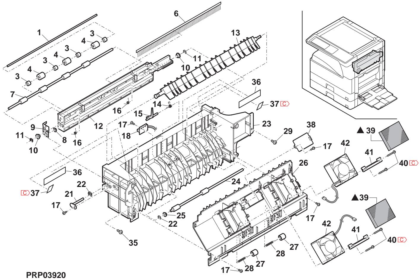
21 第一排紙1-2 (1st delivery paper unit 2)
| NO. | PARTS CODE | Inter-chang | PRICE RANK | NEW MARK | PART MARK | DESCRIPTION | TR No. | Effective time | |
| Ex. | Ja. | ||||||||
| 1 | XHBS730P08000 | AB | DD | C | Screw(3×8) | (Except North America) ヒλ | |||
| 2 | RMOTSO071QSPZ | BD | GJ | B | Shifter motor | (Except North America) フフロー- | |||
| 3 | CPLTM0184QS03 | AH | DX | C | Shifter drive plate | (Except North America) フフロー- | |||
| 4 | XEBS730P08000 | AC | DD | C | Screw(3×8) | Lλ | |||
| 5 | MSPRD0225QSZZ | AC | DJ | C | Stopper return spring | (Except North America) フフロー- 微梯 (Ex:17) LILV | |||
| 6 | LSTPP0003QSZ1 | AC | DJ | C | Shifter stopper | (Except North America) フフロー- | |||
| 7 | NGERH0068QSZ1 | AD | DJ | C | Shifter gear(50T) | (Except North America) フフロー- | |||
| 8 | NGERH0067QSZZ | AD | DJ | C | Shifter gear(24T) | (Except North America) フフロー- | |||
| 9 | VHPGP1A71L3-18 | AG | DS | B | Photo sensor(GP1A71L3) | (Except North America) フフロー- | |||
| 11 | XRESP30-06000 | AA | DD | C | E type ring(E3) | (Except North America) E LILV | |||
| 12 | XRESP40-06000 | AA | DD | C | E type ring(E4) | (Except North America) E LILV | |||
| 13 | MSPRD0216QSZZ | AD | DJ | C | Shifter earth spring | (Ex:17) LILV | |||
| 14 | MSPRT0217QSZ1 | AC | DJ | C | Gate return spring | (Ex:17) 微梯 (Ex:17) LILV | |||
| 15 | LBRC-0002QSZ1 | AC | DJ | C | Gate bracket | (Ex:17) LILV | |||
| 16 | LBSHZ030FCZZ | AC | DJ | C | M bushing C | (Ex:17) LILV C | |||
| 17 | NBRGY2122SCZZ | AB | DD | C | Transport roller bearing | (Ex:17) 駠受 | |||
| 18 | NBRGC0019QSZZ | AD | DJ | C | Bearing(φ6) | (Ex:17) 駠受 | |||
| 19 | XPSSJ30-08000 | AA | DD | C | Spring pin(φ3-8) | (Ex:17) LILV B | |||
| 20 | NBLTT0024QSZZ | AG | DS | B | Drive belt 240 | (Ex:17) LILV C | |||
| 21 | NGERH0080QSZZ | AE | DJ | C | Delivery drive gear(25/31T) | (Ex:17) 接細驅動 (Ex:17) DUP 接細圏 (Ex:17) DUP 接細圏 | |||
| 22 | NGERH0082QSZZ | AD | DJ | C | DUP delivery gear(20/31T) | (Ex:17) 接細圏 (Ex:17) DUP 接細圏 | |||
| 23 | MSPRD0198QSZZ | AC | DJ | C | Delivery earth spring B | (Ex:17) LILV B | |||
| 24 | NGERH0113QSZZ | AC | DJ | C | Idle gear B(29T) | (Ex:17) LILV B | |||
| 25 | NGERH0114QSZZ | AC | DJ | C | Idle gear C(29T) | (Ex:17) LILV C | |||
| 26 | MSPRD0196QSZZ | AC | DJ | C | Delivery earth spring A | (Ex:17) LILV A | |||
| 27 | NGERH0155QSZZ | AD | DJ | C | Gear(31/39T) | (Ex:17) | |||
| 28 | RPLU-0027QSZZ | AU | EZ | B | Change gate solenoid | (Ex:17) 切替ローツル (Ex:17) 切替ローツル | |||
| RPLU-0027QSPZ | 1 | AU | EZ | B | Change gate solenoid | (Ex:17) 切替ローツル (Ex:17) 切替ローツル | |||
| 29 | CBRC-0004QS03 | AF | DS | C | DUP motor fixing bracket | (Ex:17) 取付ローツル (Ex:17) 取付ローツル | |||
| 30 | RMOTSG0070QSPZ | BD | GJ | B | DUP motor | (Ex:17) LILV B | |||
| 31 | XHBS730P08000 | AB | DD | C | Screw(3×8) | (Ex:17) LILV C | |||
| 32 | XBBS726P03000 | - | AA | DD | C | Screw(2.6×3) | [Missing parts code] LILV (2.6×3) | ||
| 33 | XWHS730-05070 | AA | DD | C | Washer | LILV | |||
| 34 | LHLDW1334FCZZ | - | AA | DJ | C | Wire holder | LILV | ||
| 35 | PSHEZ0316QSZZ | AD | DJ | C | Delivery motor sheet | (Ex:17) 接細圏 (Ex:17) LILV | |||
| 36 | PRDAZ0002QSZZ | AD | DJ | C | Delivery motor radiation plate | (Ex:17) 接細圏 (Ex:17) 放熱板 | |||
| 37 | PSHEZ0341QSZZ | AA | DJ | C | Shifter stop mylar | (Ex:17) 接細圏 (Ex:17) 口行 | |||
| 38 | CFMR-0038RS76 | - | AX | FG | E | Shifter unit | (Ex:17) 接細圏 (Ex:17) 口行 | ||
| 39 | CFMR-0038RS54 | - | BA | FX | E | DUP motor fixing bracket unit | (Ex:17) 次付ローツル (Ex:17) 口行 | ||
| 40 | Unit | ||||||||
| 901 | CFRM-0038RS74 | BP | LP | E | 1st delivery unit(Include Block 20) (North America) | 1st 接細圏 (Ex:17) 口行 (Ex:17) 口行 (Ex:17) 口行 | |||
| CFMR-0038RS76 | - | BQ | LP | E | 1st delivery unit(Include Block 20) (Missing parts code) | 1st 接細圏 (Ex:17) 口行 (Ex:17) 口行 (Ex:17) 口行 | |||
21 第一排紙1-2 (1st delivery paper unit 2)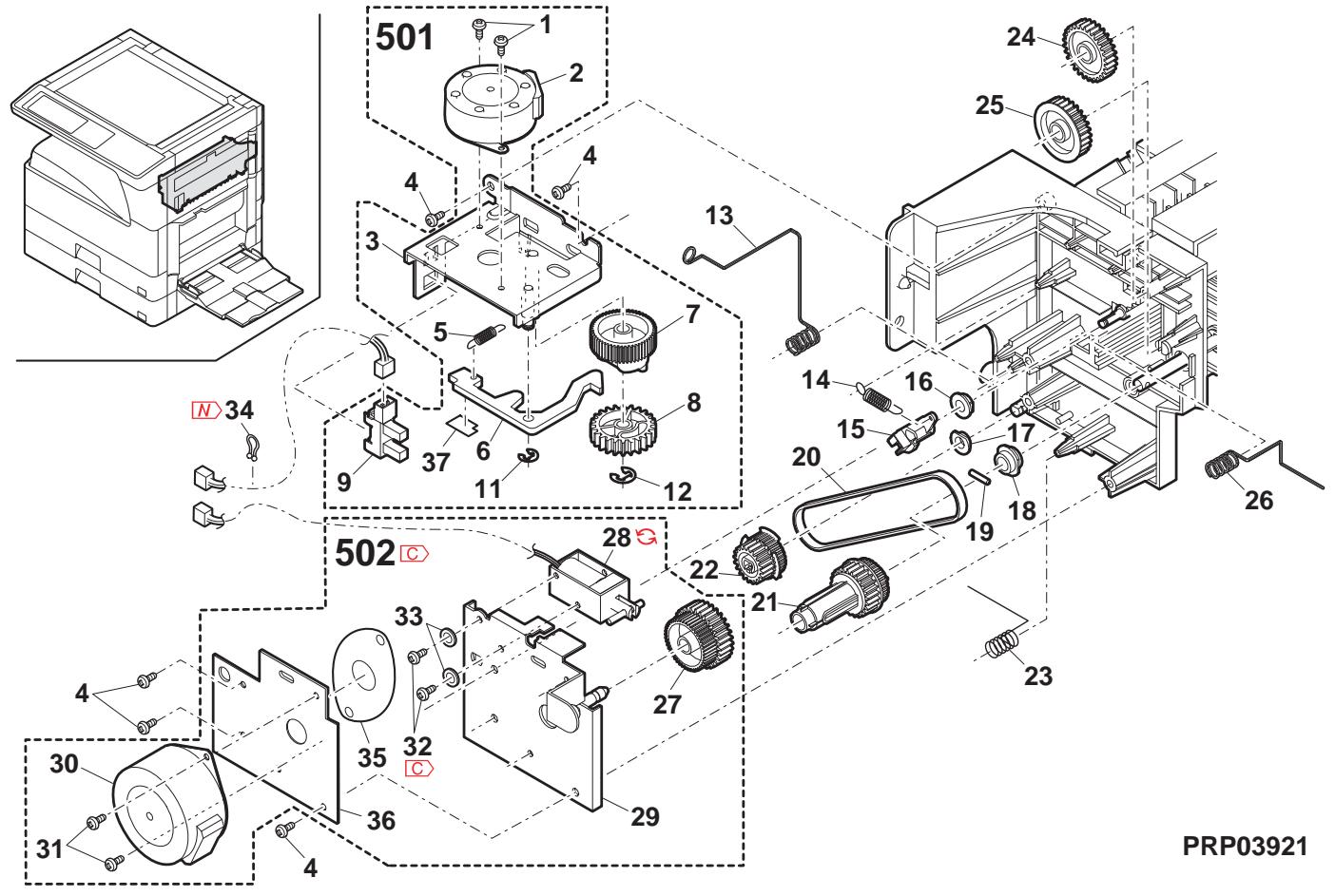
22 基板部 (PWB section)
| NO. | PARTS CODE | Inter-chang | PRICE RANK | NEW MARK | PART RANK | DESCRIPTION | TR No. | Effective time | |
| Ex. | Ja. | ||||||||
| 1 | CPWBX0136QS3L | CB | TX | E | IMC PWB [MX-M260/M260N/M260FP/M260FG,AR-5726] IMC基板 | ||||
| CPWBX0136QS3M | CB | TX | E | IMC PWB [MX-M310/M310N/M310FP,AR-5731] IMC基板 | |||||
| 2 | XBBS730P0800 | AA | DD | C | Screw(3×8) | b'λ | |||
| 3 | PSPAB039QSZZ | AG | DJ | C | Spacer | λ''-μ'' | |||
| 4 | CPWBF0235QSE1 | BB | GD | E | Option interface PWB | 打'√中继基板 | |||
| 5 | XBBS830P0800 | AA | DD | C | Screw(3×8) | b'λ | |||
| 6 | DHA i-0611QSPZ | - | AV | FG | C | AN2R MCU-OP interface harness [Missing parts code] | AN2R MCU-OP中继N-1K | ||
| 7 | LHLDZ0062QSZ2 | AT | EZ | C | MCU PWB fixing plate | MCU基板取付板 | 1st lot | ||
| 8 | LX-BZ0090QSPZ | AE | DD | C | Hexagon screw | 6角b'λ | |||
| 9 | LHLDW086QSZZ | AB | DJ | C | Harness ring LPD | h'πr'l'p'v'LPD | |||
| 10 | CPWBX0233QS31 | CD | UD | E | MCU PWB [MX-M260 North America] | MCU基板MCU基板 | |||
| CPWBX0233QS32 | CD | UD | E | MCU PWB [MX-M310 North America] | MCU基板 | ||||
| CPWBX0233QS33 | CD | UD | E | MCU PWB [MX-M260/M260FP/M260FG Except North America] | MCU基板 | ||||
| CPWBX0233QS34 | CD | UD | E | MCU PWB [MX-M310/M310N/M310FP/M310FG Except North America] | MCU基板 | ||||
| CPWBX0233QS35 | CC | UB | E | MCU PWB [AR-5726] | MCU基板 | ||||
| CPWBX0233QS36 | CC | UB | E | MCU PWB [AR-5731] | MCU基板 | ||||
| 11 | XBPS730P06KS0 | AB | DD | C | Screw(3×6KS) | b'λ | |||
| 12 | LHLDZ0071QSZZ | AG | DX | C | Mother board holder | h''-a''-b''-c''- | |||
| 13 | CPWBN0137QSE1 | AZ | FX | E | Mother board | h''-a''-b''-c''- | |||
| 14 | XHBS730P0800 | AB | DD | C | Screw(3×8) | b'λ | |||
| 15 | LX-BZ0082QSPZ | AA | DD | C | Screw(3×8) | b'λ | |||
| 16 | LHLDZ0070QSZ3 | AW | FG | C | OP PWB holder | OP基板b''-a''-b''-c''- | |||
| 17 | XHBS730P0800 | AB | DD | C | Screw(3×8) | b'λ | |||
| 18 | XEBS740P1000 | AA | DD | C | Screw(4×10) | b'λ | |||
| 19 | XBPSS730P08KS0 | AB | DD | C | Screw(3×8KS) | b'λ | |||
| 20 | PSHEZ0269QSZZ | AC | DJ | C | CCD harness sheet | CCD n-πk-μk- | |||
| 22 | DHA i-0345QSZZ | AG | DX | C | CCD harness | CCD n-πk | |||
| 23 | CPWBX0140QS3K | CM | UW | E | FAX main PWB (Japan) | FAX mK板板 | |||
| 24 | CPWBN0174QS31 | BV | MW | E | LIU PWB (Japan) | LIU 基板 | |||
| 25 | RSPA00001QSPZ | AH | DX | B | Speaker (Japan) | λ''-μ''- | |||
| 26 | XEPS730P06X0 | AA | DD | C | Screw(3×6) | j''-k''- | |||
| 27 | LSUPP0001QSZZ | AC | DJ | C | Spacer(WLS18-0) | λ''-k''- | |||
| 28 | DHA i-0606QSPZ | - | BT | MW | C | ILSW interface harness 2 [Missing parts code] | ILSW中继N-1K2 | ||
| 29 | CPWBX0202RS55 | BZ | TR | E | PCL PWB [MX-M260N/M310N] | PCL 基板 | |||
| CPWBX0202RS54 | CA | TR | E | PCL PWB [MX-M260FP/M310FP] | PCL 基板 | ||||
| 30 | PCAPH0018QSZZ | AD | DJ | D | 15P protect cap | 15P 保护N-1K | |||
| 31 | PCAPH0019QSZZ | AE | DJ | D | 25P protect cap (Except North America, Japan, Argentina) | 25P 保护N-1K | |||
| 32 | PCAPH0017QSZZ | AC | DJ | D | 9P protect cap | 9P 保护N-1K | |||
| 33 | CPWBN0135QS34 | - | BS | MW | E | SPLC PWB [Missing parts code] | SPLC 基板 | 1st lot | |
| [MX-M260/M310/M260FG/M310FG,AR-5726/5731] | |||||||||
| 35 | DHA i-0591QSP1 | - | BE | GN | C | 1st delivery harness [Missing parts code](North America) | 1st排纸N-1K | ||
| DHA i-0601QSP1 | BE | GN | C | 1st delivery harness (Except North America) | 1st排纸N-1K | ||||
| 37 | DHA i-0200QSZZ | AS | EZ | C | CL harness | CL n-πk | |||
| 38 | DHA i-0347QSPZ | AN | EQ | C | Optical sensor harness (Inch Series) | 光学N-1K | |||
| DHA i-0346QSPZ | AP | EQ | C | Optical sensor harness (AB Series) | 光学N-1K | ||||
| 39 | DHA i-0506QSPZ | AQ | EQ | C | LSU interface harness | LSU 中继N-1K | |||
| 40 | DHA i-0593QSPZ | - | BF | GN | C | Drive/Manual paper feed interface harness [Missing parts code]驱动/手差L | 驱动/手差L | ||
| 41 | DHA i-0350QSPZ | AG | DX | C | Cassette sensor PWB harness | h''-k''-k''-k''-k''-k''-k''-k''-k''-k''-k''-k''-k''-k''-k''-k''-k''-k''-k''-k''-k''-k''-k''-k''-k''-k''-k''-k''-k''-k''-k''-k''-k''-k''-k'' 42 | DHA i-0610QSP1 | ||
| DHA i-0381QSPZ | AH | DX | C | Fusing interface harness | 定着中继N-1K | ||||
| 43 | DHA i-0594QSPZ | - | BG | GT | C | AN2R power supply harness [Missing parts code] | AN2R 電源N-1K | ||
| TLABH0533QSZZ | AB | DJ | D | USB label AND | USB f''-k''-k''-k''-k''-k''-k''-k''-k''-k''-k''-k''-k''-k''-k''-k''-k''-k''-k''-k''-k''-k''-k''-k''-k''-k''-k''-k''-k''-k''-k''-k''-k''-k" | ||||
| TLABH0534QSZZ | AB | DJ | D | NIC label AND [Except MX-M260FG/M310FG] | NIC f''-k''-k''-k''-k''-k''-k''-k''-k''-k''-k''-k''-k''-k''-k''-k''-k''-k''-k''-k''-k''-k''-k''-k''-k''-k''-k''-k''-k''-k''-k''-k''-k''-K" | ||||
| RTCH0161FCP1 | AV | FG | B | Temperature humidity sensor | 温度湿度N-1K | ||||
| 72 | DHA i-0595QSPZ | AE | DS | C | Temperature humidity sensor harness | 温度湿度N-1K | |||
| 73 | LSUPM0002QSZZ | AE | DJ | C | Support post [MX-M260N/M310N/M260FP/M310FP] | f''-b''-b''-b''-b''-b''-b''-b''-b''-b''-b''-b''-b''-b''-b''-b''-b''-b''-b''-b''-b''-b''-b''-b''-b''-b''-b''-b''-b''-b''-b''-b''-b''-b''-b'' 44 | VCORF0046FCZZ | ||
| RCORF0046FCZZ | AH | DX | C | Core | ∅ | ||||
| RCORF0046FCZZ | - | AH | DX | C | Core | ∅ | |||
| 75 | DHA i-0597QSP1 | - | BF | GN | C | MCU-casette harness [Missing parts code] | MCU-加T''-k''-k''-k''-k''-k''-k''-k''-k''-k''-k''-k''-k''-k''-k''-k''-k''-k''-k''-k''-k''-k''-k''-k''-k''-k''-k''-k''-k''-k''-k''-k''-k''-k" 80 | DHA i-0590QSPZ | |
| VH i 29L 1607DQS | BB | GD | B | MCU ROM [MX-M260 North America] | MCU ROM | ||||
22 基板部 (PWB section)
| NO. | PARTS CODE | Inter-changese | PRICE RANK | NEWMARK | PARTRANK | DESCRIPTION | TR No. | Effective time | |
| Ex. | Ja. | ||||||||
| 84 | VH i 29 L 32077QS | AZ | FQ | B | PCL BOTDIMMJ [MX-M260N/M310N Philippines] PCLBOTDIMMJ | ||||
| VH i 29 L 32079QS | AZ | FX | B | PCL BOTDIMMJ [MX-M260N/M310N Except Philippines] PCLBOTDIMMJ | |||||
| VH i 29 L 64012QS | BD | GN | B | PCL BOTDIMMJ [MX-M260FP/M310FP] PCLBOTDIMMJ | |||||
| 85 | LBND J0013FCZ1 | AE | DJ | C | Band\( {\lambda }^{ \circ } \)h* | ||||
| 86 | PSPAN0025QSZZ | AE | DS | C | Spacer\( {\lambda }^{ \circ } -\frac{1}{4} - \) | ||||
| 87 | LX-BZ0024QSZZ | AA | DD | C | Screw\( {t}^{ \circ } \)\( \lambda \) | ||||
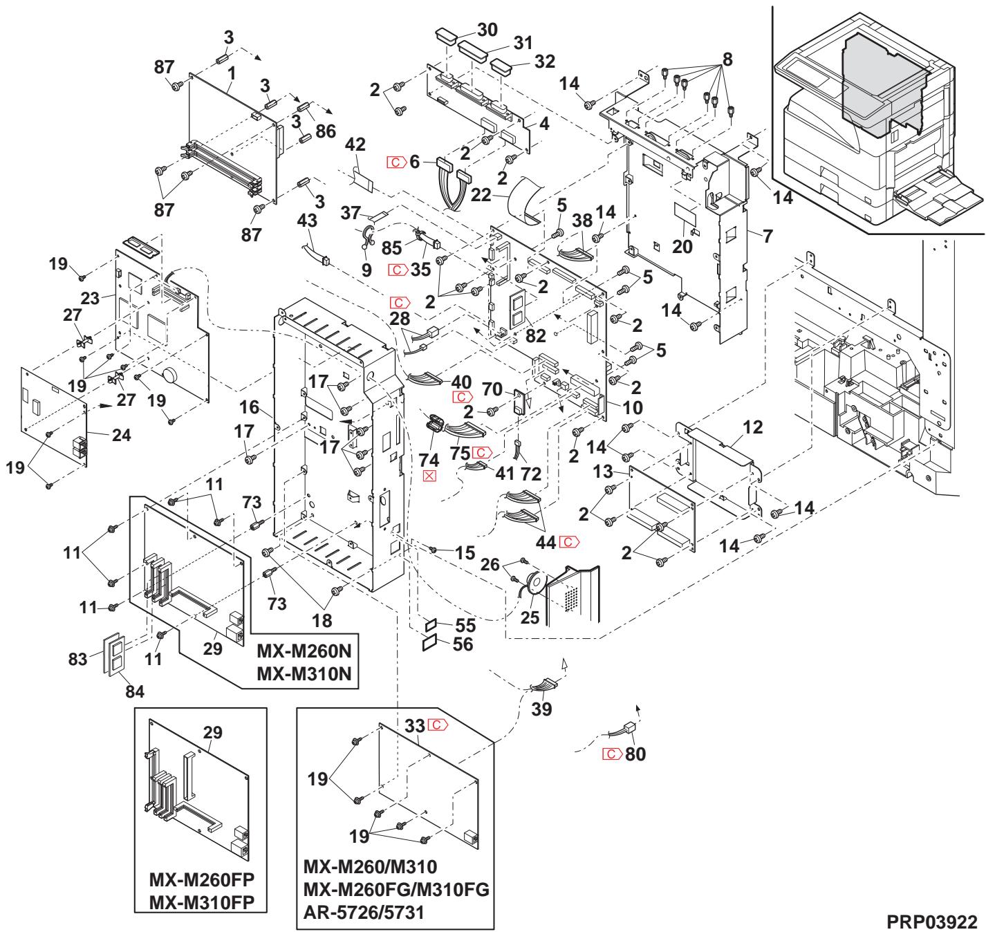
23 後フレーム部 (Rear frame section)
| NO. | PARTS CODE | Inter-changese | PRICE RANK | NEW MARK | PART | DESCRIPTION | TR No. | Effective time | |
| Ex. | Ja. | ||||||||
| 1 | XBP SN 40 P 06 K 00 | - | AA | DD | C | C | Screw(4×6K) | t'λ | |
| 2 | DHA i - 0596QSPZ | - | BT | MW | C | C | AN2R HL interface harness [Missing parts code] | AN2R HL 中继n-λ | |
| 3 | TLABZ 4868 FCZ1 | - | AB | DJ | D | D | Earth label (200V Series) | t'λ | |
| 4 | XHBS 730P 06000 | - | AC | DD | C | C | Screw(3×6) | t'λ | |
| 5 | LPLTM 162QSZ1 | - | AC | DJ | C | C | Drive earth plate | 驱動7-λ板 | |
| 6 | LPLTM 0252QSZZ | - | AD | DJ | C | C | Paper feed earth plate LP | 給紙7-λ板LP | |
| 7 | DHA i - 0593QSPZ | - | BF | GN | C | C | Drive/Manual paper feed interface harness [Missing parts code] | 驱動/手差L 中继n-λ | |
| 8 | DHA i - 0378QSPZ | - | AC | DJ | C | C | Cassette earth harness | 地拉T-λn-λ | |
| 9 | XHBS 730P 08000 | - | AB | DD | C | C | Screw(3×8) | t'λ | |
| 10 | XEBS 740P 30000 | - | AC | DD | C | C | Screw(4×30) | t'λ | |
| 11 | PG DM0 184QSZ1 | - | AH | DX | C | C | Harness guide | n-λn-λ' n" | |
| 12 | XEBS 740P 30000 | - | AC | DD | C | C | Screw(4×30) | t'λ | |
| 13 | CDA i U024RS57 | - | AZ | FQ | E | 1st lift up unit | 1st lrrr7-7' 7-7' 7-7' | ||
| 15 | LPLTM 0249QSZZ | - | AC | DJ | C | 2nd earth plate | 2nd T-λ板 | ||
| 19 | QACCD 7713QCPZ | - | AT | EZ | B | AC cord (North America) AC n-1" | |||
| QACCB 7623QCPZ | - | BB | GD | B | AC cord (U.kingdom,UAE,Yemen,Oman,Qatar, Kuwait,Bahrain) AC n-1" | ||||
| QACCVR 621QCPZ | - | AQ | FQ | B | AC cord (Germany.Switzerland,Europe,East Europe, Algeria,Iran,Egypt,Syrta,Tunisia,Nigeria, West Africa,Morocco,Jordan,Lebanon) AC n-1" | ||||
| QACCZR 626QCPZ | - | BB | GD | B | AC cord (Philippines) AC n-1" | ||||
| QACCZR 941QCPZ | - | BB | FX | B | AC cord (Thailand,Indonesia) AC n-1" | ||||
| QACC89521QCZ | - | AW | FG | B | AC cord (India.Special country,Malaysia,Singapore) AC n-1" | ||||
| QACCJ 6413QCPA | - | AY | FQ | B | AC cord (Japan) AC n-1" | ||||
| QACCLR 624QCPZ | - | BA | FX | B | AC cord (Australia,New Zealand) AC n-1" | ||||
| QACCR 7621QCZZ | - | AZ | FQ | B | AC cord (Argentina) AC n-1" | ||||
| QPLGA 4171CCPZ | - | AR | EQ | B | Plug (India) T'λ" | ||||
| QPLGA 0001QCZ | - | AN | EQ | B | Plug (Special country) T'λ" | ||||
| QPLGA 0009QCPZ | - | AR | EQ | B | Plug (Malaysia,Singapore) T'λ" | ||||
| PHOG-1023CCZZ | - | AB | DD | B | Plug protector (India,Malaysia,Singapore) T'λ"用保護 | ||||
| TCAUS 0009QSZZ | - | AF | DS | D | LAG Plug caution label (Argentina) LAG T'λ" 注意" | ||||
| 20 | QSW-C9295QCPZ | - | AL | EB | B | Power supply switch(AJ8W200BF) 電源λ" | |||
| 21 | QSW-C9294QCZZ | - | AF | DS | B | Dehumidify heater switch (Japan) 除湿T-λ" | |||
| 22 | DHA i - 0589QSPZ | - | BS | MW | C | Dehumidify heater switch harness (Japan) 除湿T-λ" | |||
| 23 | DHA i - 0545QSPZ | - | AH | DX | C | Dehumidify heater separate harness (Japan) 除湿T-λ" | |||
| 24 | RCi LZ0016QSZZ | - | BE | GN | C | Reactle (200V) T'λ" | |||
| 28 | RDENC 0052QSPZ | - | BZ | TF | E | Low voltage power supply unit (120V) 低压电源n-1" | |||
| RDENC 0053QSPZ | - | BZ | TF | E | Low voltage power supply unit (230V) 低压电源n-1" | ||||
| RDENC 0051QSPZ | - | BZ | TF | E | Low voltage power supply unit (100V) 低压电源n-1" | ||||
| 29 | RDENU 0058QSPZ | - | BN | LE | E | High voltage power supply unit 高压电源n-1" | |||
| 30 | LHLDW 1057FCZZ | - | AB | DD | C | Wire saddle(LWS-3S) T'λ" | |||
| 31 | DHA i - 0588QSPZ | - | BF | GN | C | AC switch harness (Missing parts code) AC λ"n-λ" | |||
| LFi X-0016FCZZ | - | AD | DJ | C | AC cord fixing (100V Series) AC n-1"押元 | ||||
| 33 | XEBS 740P30000 | - | AC | DD | C | Screw(4×30) t'λ | |||
| 34 | XEBS 740P12000 | - | AA | DD | C | Screw(4×12) t'λ | |||
| 35 | XWHS 740-08100 | - | AA | DD | C | Washer t'λ" | |||
| 36 | XWSS 740-10000 | - | AA | DD | C | Washer n'初n-1" | |||
| 37 | LPLTM 0349QSZZ | - | AS | EQ | C | Power supply fixing plate 電源取付板 | |||
| 38 | NFANP 0020QSPZ | - | AP | EQ | B | P/S fan motor PS f"n-λ" | |||
| 39 | XBPS 730P30KS0 | - | AC | DD | C | Screw(3×30KS) t'λ" | |||
| 42 | XBPS 730P08KS0 | - | AB | DD | C | Screw(3×8KS) t'λ" | |||
| 45 | LPLTM 0369QSZZ | - | AG | DS | C | Delivery support angle 接线保持T'λ" | |||
| 46 | XHB 740P10000 | - | AA | DD | C | Screw(4×10) t'λ" | |||
| 47 | LSUPP 0133FCPZ | - | AC | DJ | C | PWB supporter 基板n-1" | |||
| 49 | RCORF 0031QSPZ | - | AK | DX | C | Core n'初n-1" | |||
| 50 | LNBJD 0013FCZ1 | - | AE | DJ | C | Band 结束n" | |||
| 51 | LHLDW 1154FCZZ | - | AC | DJ | C | Wire saddle(LWS5S2W) T'λ" | |||
| 52 | LBNDJ 0037FCZ1 | - | AA | DJ | C | Band 结束n" | |||
| 53 | PTUBP 0012QSZZ | - | AC | DJ | C | Tube(F5×20) t'λ" | |||
| 54 | RCORF 0004QSZZ | - | AF | DS | C | Core (200V Series) n-1" | |||
| 55 | LBSHC 0008QSZ | - | AC | DJ | C | Edging(L=32) (200V Series) n'g" | |||
| 56 | LPLTM 0478QSZZ | - | AC | FS | C | AC Inlet fixing plate (200V Series) AC n'ul" 取付板 | |||
| 57 | XHSS 730P06000 | - | AB | DD | C | Screw(3×6) (200V Series) t'λ" | |||
| 58 | NEXBS 730P12000 | - | AC | DD | C | Screw(3×12) t'λ" | |||
| 59 | XEBS 730P10000 | - | AC | DD | C | Screw(3×10) (200V Series) t'λ" | |||
23 後フレーム部 (Rear frame section)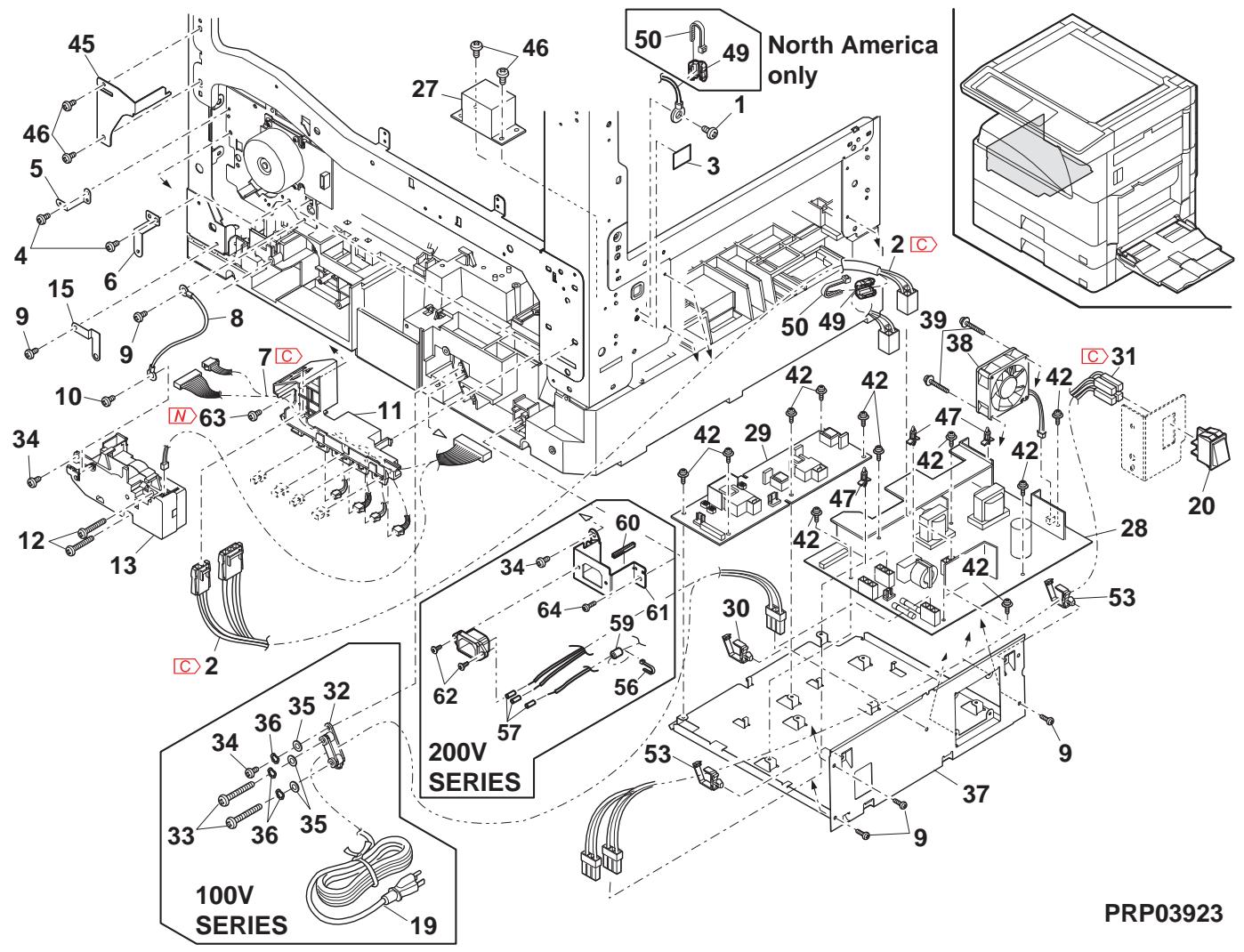
27 2nd 搬送部 (2nd paper transfer section)
| NO. | PARTS CODE | Inter-chang | PRICE RANK | NEW MARK | PART RANK | DESCRIPTION | TR No. | Effective time | |
| Ex. | Ja. | ||||||||
| 1 | MSPRC0378QSZ1 | AB | DJ | C | Lock spring リリスリフ | ||||
| 2 | MLOKZ0001QSZZ | AC | DJ | C | Paper guide lock リリスリフ | ||||
| 3 | XEPS730P08X00 | AA | DD | C | Screw(3×8X) | ||||
| 4 | PG i DM0068QSZ1 | AP | EG | C | Transport paper guide 搬送 リリスリフ | ||||
| 5 | MARMP0015QSZZ | AD | DJ | C | 2nd door arm 2nd ト 77-44 | ||||
| 6 | NSFTZ0054QSZ1 | AD | DJ | C | Transport paper guide shaft 搬送 リリスリフ | ||||
| 7 | NROLP1060FCZZ | AF | DS | C | U-turn roller Uケーダ-44 | ||||
| 8 | MSPRP0345QSZ1 | AD | DJ | C | Transport paper guide spring 搬送 リリスリフ | ||||
| 9 | XEBS730P08000 | AC | DD | C | Screw(3×8) リリス | ||||
| 10 | GCÖVA0026QSTC | - | AP | EQ | D | Right cover [Missing parts code] 右加 - | 1st lot | ||
| 11 | XEBS730P10000 | AC | DD | C | Screw(3×10) リリス | ||||
| 12 | PCÖVP0089QSZZ | AD | DJ | D | Plate cover フレット 加 - | ||||
| 13 | LPLTP0409QSZZ | AC | DJ | C | Separator plate AND2 搏きフレットAND2 | ||||
| 14 | PSHEZ0515QSZZ | AG | DX | A | Separator sheet 搏きシト | ||||
| 15 | NROLR0130QSZZ | AL | EB | C | Transport roller 搏送は-44 | ||||
| 16 | MSPRC0270QSZZ | AB | DJ | C | Separator plate spring 搏きフレット リリス | ||||
| 17 | NBRGZ0503FCZZ | AC | DJ | C | Bearing 軸受 | ||||
| 18 | LSTPP0011QSZZ | AC | DJ | C | Resin E type ring 树脂 E 錄 | ||||
| 19 | LRALP0009QSZ2 | AP | EQ | C | Cassette rail R カリル R | ||||
| 20 | XBPS730P08KS0 | AB | DD | C | Screw(3×8KS) リリス | ||||
| 21 | NKOM-0005QSZZ | AC | DJ | C | Cassette guide collar 加さリドコ | ||||
| 22 | NSFTZ0048QSPZ | AF | DS | C | Cassette collar shaft 加さリド軸 | ||||
| 23 | PG i DM0074QSZZ | AK | DX | C | 2nd U-turn guide 2ndUケーダ-44 | ||||
| 24 | XEBS740P12000 | AA | DD | C | Screw(4×12) リリス | ||||
| 25 | PSHEZ0301QSZZ | AC | DJ | C | Rail R side sheet F [leel R ナリス] 空地 F | ||||
| 26 | PSHEZ0302QSZZ | AC | DJ | C | Rail R side sheet R [leel R ナリス] 空地 R | ||||
| 27 | MSPRD0287QSZZ | AC | DJ | C | Paper feed sub roller spring 絡紙補助ローラ- リリス | ||||
| 28 | NROLP0087QSZZ | AD | DJ | C | Paper feed sub roller 絡紙補助ローラ- | ||||
| 29 | NSFTZ0101QSZZ | AC | DJ | C | Paper feed sub roller shaft 絡紙補助ローラ- | ||||
| 30 | PSHEZ0356QSZ1 | AE | DS | C | Plate cover sheet フレット 加 - | ||||
| 31 | PSHEZ0347QSZ1 | AC | DJ | C | 2nd rail R sheet 2nd leel R 裁 | ||||
| 32 | LPLTM0396QSZ1 | AD | DJ | C | Separator guide plate 搏きフレット | ||||
| 33 | PSPAZ0055QSZZ | AA | DJ | C | Plate cover spacer フレット 加 - リリス | ||||
| 34 | LX-WZ0064FCZZ | AA | DD | C | Push nut(M3) フリス | ||||
| 501 | CCOVP0089RS55 | - | AP | EQ | E | Plate cover unit [Missing parts code] フレット 加 - 空地 | 1st lot | ||
| 502 | CG i DM0068RS55 | - | AU | EZ | E | Transport paper guide unit [Missing parts code] 搏送 フレット 加 - 空地 | 1st lot | ||
| 503 | CPLTP0409RS51 | AN | EG | C | Separation plate unit 分離フレット | ||||
| 504 | |||||||||
| 505 | |||||||||
| 506 | |||||||||
| 507 | |||||||||
| 508 | |||||||||
| 509 | |||||||||
| 510 | |||||||||
| 511 | |||||||||
| 512 | |||||||||
| 513 | |||||||||
| 514 | |||||||||
| 515 | |||||||||
| 516 | |||||||||
| 517 | |||||||||
| 518 | |||||||||
| 519 | |||||||||
| 520 | |||||||||
| 521 | |||||||||
27 2nd 搬送部 (2nd paper transfer section)
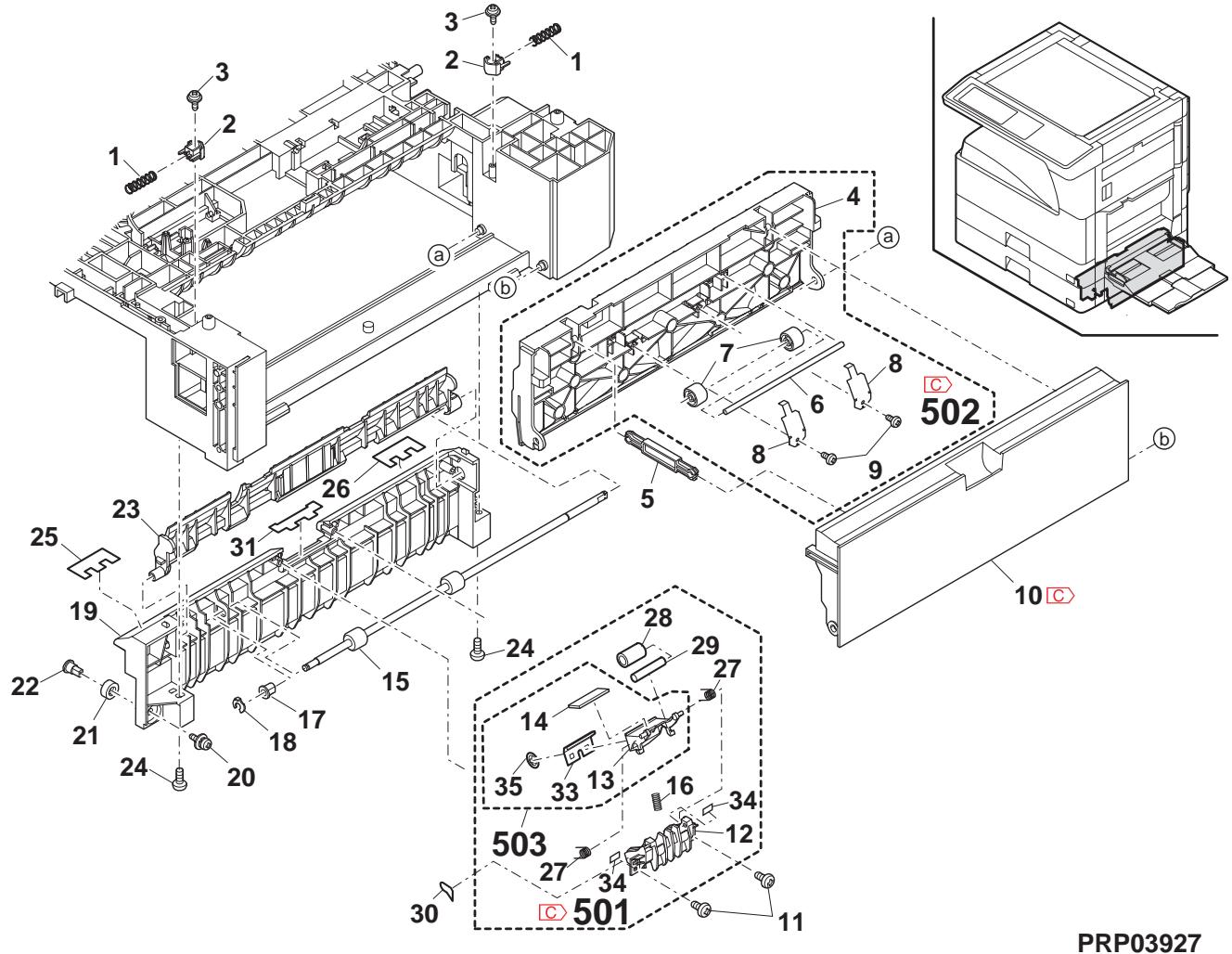
25 2nd 550カセットユニット (2nd 550 cassette unit)
| NO. | PARTS CODE | Inter-changese | PRICE RANK | NEW MARK | PART RANK | DESCRIPTION | TR No. | Effective time | |
| Ex. | Ja. | ||||||||
| 1 | LPLTP0159QSZZ | AD | DJ | C | Cassette rear edge plate 保後端板 | ||||
| 2 | LHLDW1226FCZZ | AB | DJ | C | Turn fastener トフフフフ | ||||
| 3 | LPLTM0179QSZ1 | AR | EQ | C | Rotation plate 回軸板 | ||||
| 4 | PSHEZ0274QSZZ | AC | DJ | C | Rotation plate sheet 回軸板←ト | ||||
| 5 | GCAS0005QSZ4 | BA | GD | D | 550 cassette 550 豉伏 | ||||
| 6 | PGiDM0070QSZ1 | AM | EG | C | Guide F 保伏F | ||||
| 7 | PTPE-0021QSZ1 | - | AA | DJ | C | GID tape [Missing parts code] GID 两面→F | 1st lot | ||
| 8 | LPLTM0181QSZ1 | AB | DJ | C | Side plate guide F 侧板"伏F | ||||
| 9 | PGiDM0071QSZ | AL | EB | C | Guide R 保伏R | ||||
| 10 | LX-BZ1144FCPZ | AA | DD | C | Screw 保λ | ||||
| 11 | NGERH0193FCZZ | AB | DD | C | UC manual paper feed gear UC手差←↑ | ||||
| 12 | MSPRC2631FCZZ | AC | DJ | C | Fusing pressure spring 定着加压 ムリフ | ||||
| 13 | MLEVP0755FCZ1 | AE | DJ | C | Side plate F lever 侧板F←- | ||||
| 14 | LX-BZ0833FCPZ | AC | DD | C | Screw 保λ | ||||
| 15 | CSHEZ0244QS02 | AE | DJ | C | 2nd cassette sheet ASS'Y 2nd応伏ト組品 | ||||
| 16 | XRESP70-08000 | AA | DD | C | E type ring(E7) E リフ伏 | ||||
| 17 | NGERH0108QSZZ | AD | DJ | C | Lift gear(22T) 保伏 | ||||
| 18 | MSPRC0354QSZZ | AC | DJ | C | Lift gear spring 保伏 水伏 | ||||
| 19 | NSFTZ0047QSZ1 | AK | EB | C | Lift shaft トフフ伏 | ||||
| 20 | LPLTM0180QSZ1 | AE | DS | C | Lift plate トフ伏 | ||||
| 21 | NBRGP0041GCZZ | AD | DJ | C | Bearing 軸受 | ||||
| 22 | XEBS74010000 | AA | DD | C | Screw(4×10) 保λ | ||||
| 23 | JHNDP0012QSZZ | AU | EZ | C | 2nd cassette panel AN2R 2nd応伏ト ミル AN2R | ||||
| 24 | XBPS740P08KS0 | AB | DD | C | Screw(4×8KS) 保λ | ||||
| 25 | GCōV-0282FCZZ | AH | DX | D | Cassette handle cover P2 保伏 口手伏 -P2 | ||||
| 26 | PSHEZ5948FCZZ | AD | DJ | C | Cassette handle sheet P2 保伏 口手伏 P2 | ||||
| 27 | LPLTM0277QSZZ | AC | DJ | C | Side plate guide R 侧板"伏R | ||||
| 28 | XEBS730P08000 | AC | DD | C | Screw(3×8) 保λ | ||||
| 29 | TCADZ0549QSZZ | - | AE | DS | D | Size display card [Missing parts code](Inch Series) 保伏 表示→ | 1st lot | ||
| TCADZ0550QSZZ | AE | DS | C | Size display label (AB Series except Japan) 保伏 表示→ | |||||
| TCADZ0551QSZZ | AE | DS | C | Size display label (Japan) 保伏 表示→ | |||||
| 501 | CCASP0005RS79 | - | BF | GN | E | 2nd 550 cassette unit [Missing parts code] 2nd 550 豉伏 ミフ伏 | 1st lot | ||
| (Unit) | |||||||||
| 901 | CCASP0005RS59 | BK | HC | E | 2nd 550 cassette unit(Without No.30) 2nd 550 豉伏 ミフ伏 (No.30を除く) | ||||
2nd 550カセットユニット (2nd 550 cassette unit)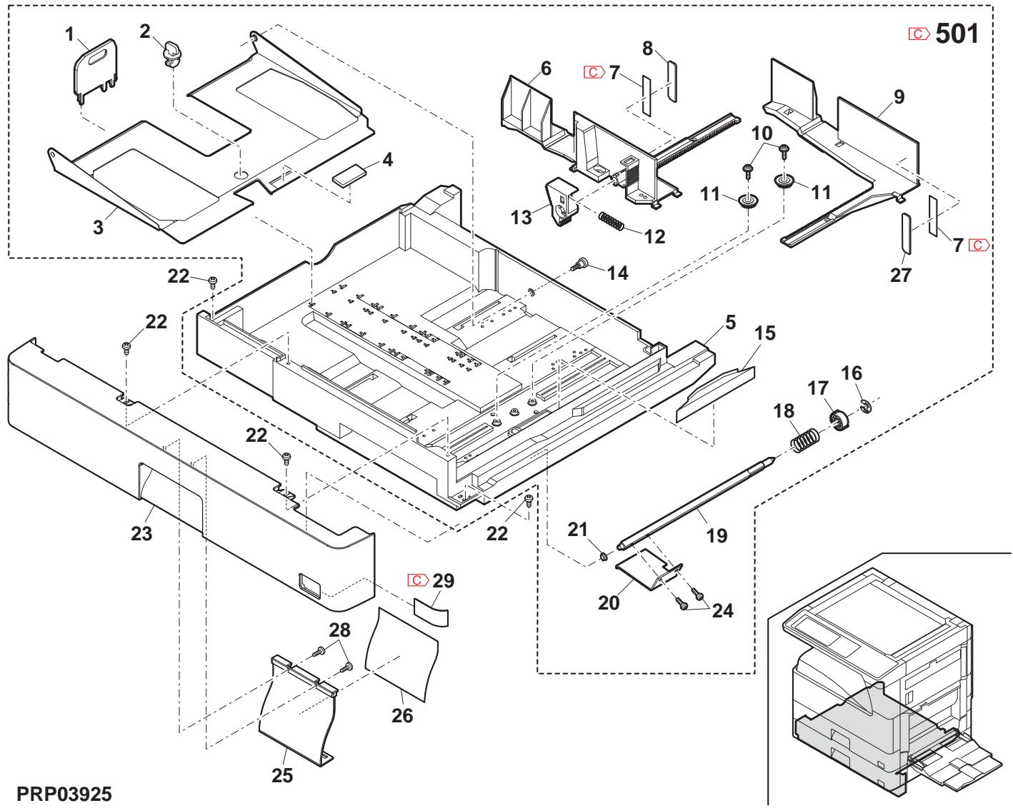
26 2nd 給紙部 (2nd paper feed section)
| NO. | PARTS CODE | Inter-chang | PRICE RANK | NEW MARK | PART RANK | DESCRIPTION | TR No. | Effective time | ||
| Ex. | Ja. | |||||||||
| 2 | PCOVP 0070QSZZ | AD | DJ | D | Sensor cover | せんが一。 | ||||
| 4 | CPWBFO095QSE3 | AP | EQ | E | 2nd cassette sensor PWB | 2nd イルバーナー基板 | ||||
| 5 | MLEVP 0063QSZ1 | AD | DJ | C | Upper limit detect actuator | 上限検知70000000000000000000000000000000000000000000000000000000000000000000000000000000000000000000000000000 | ||||
| 6 | MLEVP 0064QSZZ | AD | DJ | C | Paper detect actuator | 紙検知700000000000000000000000000000000000000000000000000000000000000000000000000000000000000000000000 | ||||
| 7 | MLEVP 0062QSZZ | AC | DJ | C | P-IN detect actuator | 入紙検知70000000000000000000000000000000000000000000000000000000000000000000000000000000000000000000000 | ||||
| 8 | PCOVP 0064QSZZ | AD | DJ | D | Solenoid cover | ルフク。 | ||||
| 9 | RPLU-0026QSZ1 | AR | EQ | B | Paper feed solenoid | 給紙ルフク。 | ||||
| RPLU-0026QSP1 | 1 | AR | EQ | B | Paper feed solenoid | 給紙ルフク。 | ||||
| 10 | MARMP 0026QSZZ | AD | DJ | C | Solenoid arm | ルフク。 | ||||
| 11 | MSPRC0209QSZ1 | AC | DJ | C | Solenoid spring | ルフク。 | ||||
| 13 | NSFTZ0102QSZZ | AH | DX | C | 2nd paper feed roller shaft | 2nd 結紙ローナーベ轴 | ||||
| 14 | QSW-B0017QSZZ | AF | DS | B | Tray detect switch | トレ検知4000 | ||||
| 17 | DHA i-0397QSPZ | AD | DJ | C | Cassette detect interface harness | かす検知中縫ハス | ||||
| 18 | NBRGC0100FCZ1 | AC | DJ | C | Bearing 6 | ^ リリカ。6 | ||||
| 19 | MSPRD0389QSZZ | AC | DJ | C | Pick up roller pressure spring | t'' リリカ。加圧λ'' リリカ。 | ||||
| 20 | MARMP 0021QSZZ | AD | DJ | C | Pick up arm R | t'' リリカ。7000R | ||||
| 21 | NGERH0107QSZZ | AD | DJ | C | Paper feed gear(20T) | 給紙状。 | ||||
| 22 | LPiN-0026MCZZ | AA | DD | C | Spring pin(φ2-8) | t'' リリカ。7000 | ||||
| 23 | NROLR0132QSZ1 | AR | EQ | C | Paper feed roller AND2 | 給紙ローナーAND2 | ||||
| 24 | MARMP 0019QSZZ | AD | DJ | C | Pick up arm F | t'' リリカ。7000F | ||||
| 25 | NGERH0990FCZZ | AB | DJ | C | Gear(16T) | t'' 中 | ||||
| 27 | NROLR0133QSZZ | AC | DJ | C | Paper feed in detect actuator spring | 入紙検知7000。 | ||||
| 29 | DHA i-0394QSPZ | AD | DJ | C | Door open/close detect harness | 7開閉検知ハス | ||||
| 30 | MSPRD0204QSZZ | AC | DJ | C | Paper feed in detect actuator spring | 入紙検知7000。 | ||||
| 31 | DHA i-0473QSP1 | AG | DX | C | Cassette sensor PWB harness | かす検知基板ハス | ||||
26 2nd 給紙部 (2nd paper feed section)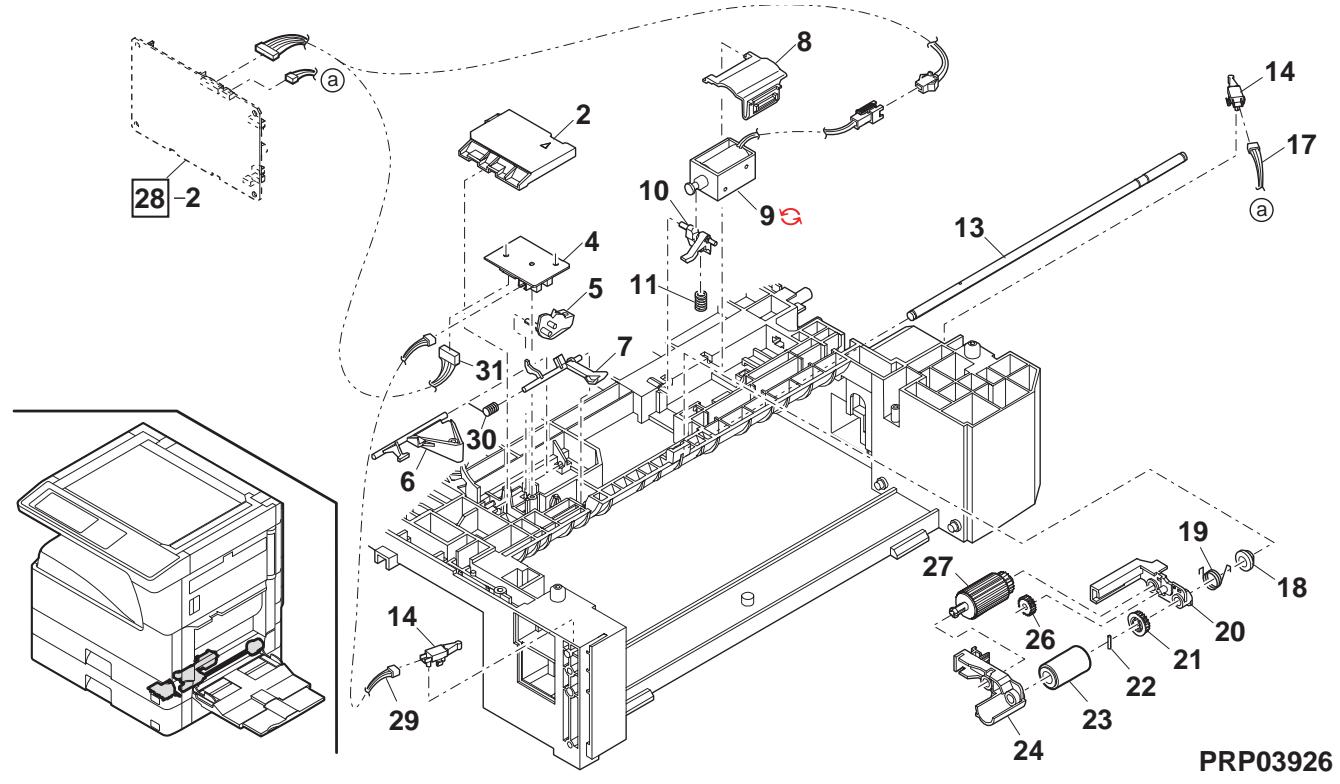
27 2e section de transport du papier (2nd paper transfer section)
| NO. | PARTS CODE | Inter-chang | PRICE RANK | NEW MARK | PART RANK | DESCRIPTION | TR No. | Effective time | ||
| Ex. | Ja. | |||||||||
| 1 | MSPRC0378QSZ1 | AB | DJ | C | Lock spring リルフリル | |||||
| 2 | MLOKZ0001QSZZ | AC | DJ | C | Paper guide lock チ-n-が応つロル | |||||
| 3 | XEPS730P08X00 | AA | DD | C | Screw(3×8X) ヤλ | |||||
| 4 | PG i DM0068QSZ1 | AP | EG | C | Transport paper guide 搬送 チ-n-が応つロル | |||||
| 5 | MARMP0015QSZZ | AD | DJ | C | 2nd door arm 2nd ト77-4 | |||||
| 6 | NSFTZ0054QSZ1 | AD | DJ | C | Transport paper guide shaft 搬送 チ-n-が応つロル 油ト | |||||
| 7 | NROLP1060FCZZ | AF | DS | C | U-turn roller Uケーダ-4 | |||||
| 8 | MSPRP0345QSZ1 | AD | DJ | C | Transport paper guide spring 搬送 チ-n-が応つロル ラルの | |||||
| 9 | XEBS730P08000 | AC | DD | C | Screw(3×8) ヤλ | |||||
| 10 | GCÖVA0026QSTC | - | AP | EQ | D | Right cover [Missing parts code] 右加一 | 1st lot | |||
| 11 | XEBS730P10000 | AC | DD | C | Screw(3×10) ヤλ | |||||
| 12 | PCÖVP0089QSZZ | AD | DJ | D | Plate cover フレトカ一 | |||||
| 13 | LPLTP0409QSZZ | AC | DJ | C | Separator plate AND2 搏きフレトAND2 | |||||
| 14 | PSHEZ0515QSZZ | AG | DX | A | Separator sheet 搏きドト | |||||
| 15 | NROLR0130QSZZ | AL | EB | C | Transport roller 搏送は一 | |||||
| 16 | MSPRC0270QSZZ | AB | DJ | C | Separator plate spring 搏きフレト ラルの | |||||
| 17 | NBRGZ0503FCZZ | AC | DJ | C | Bearing 軸受 | |||||
| 18 | LSTPP0011QSZZ | AC | DJ | C | Resin E type ring 栅脂 ELLR | |||||
| 19 | LRALP0009QSZ2 | AP | EQ | C | Cassette rail R カリルR | |||||
| 20 | XBPS730P08KS0 | AB | DD | C | Screw(3×8KS) ヤλ | |||||
| 21 | NKOM-0005QSZZ | AC | DJ | C | Cassette guide collar 加ささささささささささささささささささささささささささささささささささささささささささささささささささささささささささささささささささささささささささささささささささささささささささささささささささささ | |||||
| 22 | NSFTZ0048QSPZ | AF | DS | C | Cassette collar shaft 加さささささささささささささささささささささささささささささささささささささささささささささささささささささささささささささささささささささささささささささささささささささささささささささささささ | |||||
| 23 | PG i DM0074QSZZ | AK | DX | C | 2nd U-turn guide 2ndUケーダ-4 | |||||
| 24 | XEBS740P12000 | AA | DD | C | Screw(4×12) ヤλ | |||||
| 25 | PSHEZ0301QSZZ | AC | DJ | C | Rail R side sheet F カルR栓钉F | |||||
| 26 | PSHEZ0302QSZZ | AC | DJ | C | Rail R side sheet R カルR栓钉R | |||||
| 27 | MSPRD0287QSZZ | AC | DJ | C | Paper feed sub roller spring 絡紙補助ローラル ラルの | |||||
| 28 | NROLP0087QSZZ | AD | DJ | C | Paper feed sub roller 絡紙補助ローラル | |||||
| 29 | NSFTZ0101QSZZ | AC | DJ | C | Paper feed sub roller shaft 絡紙補助ローラル | |||||
| 30 | PSHEZ0356QSZ1 | AE | DS | C | Plate cover sheet フレトカ一 | |||||
| 31 | PSHEZ0347QSZ1 | AC | DJ | C | 2nd rail R sheet 2nd しぃルR栓钉 | |||||
| 32 | LPLTM0396QSZ1 | AD | DJ | C | Separator guide plate 搏きフレトFR | |||||
| 33 | PSPAZ0055QSZZ | AA | DJ | C | Plate cover spacer フレトカ一 ラルの | |||||
| 34 | LX-WZ0064FCZZ | AA | DD | C | Push nut(M3) ユルフリル | |||||
| 501 | CCOVP0089RS55 | - | AP | EQ | E | Plate cover unit [Missing parts code] モルフリル一。一。一。一。一。一。一。一。一。一。一。一。一。一。一。一。一。一。一。一。一。一。一。一。一。一。一。一。一。一。一。一。一。一。一。一。一。一。一。一。一。一。一。一。一。一。一。一。一。一。一。 ラルの | ||||
| 502 | CG i DM0068RS55 | - | AU | EZ | E | Transport paper guide unit [Missing parts code] 搏送 チ-n-が応つロル ダルの | ||||
| 503 | CPLTP0409RS51 | AN | EG | E | Separation plate unit 分離フレト工部 | |||||
| 504 | ||||||||||
| 505 | ||||||||||
| 506 | ||||||||||
| 507 | ||||||||||
| 508 | ||||||||||
| 509 | ||||||||||
| 510 | ||||||||||
| 511 | ||||||||||
| 512 | ||||||||||
| 513 | ||||||||||
| 514 | ||||||||||
| 515 | ||||||||||
| 516 | ||||||||||
| 517 | ||||||||||
| 518 | ||||||||||
| 519 | ||||||||||
| 520 | ||||||||||
| 521 | ||||||||||
27 2e section de transport du papier (2nd paper transfer section)
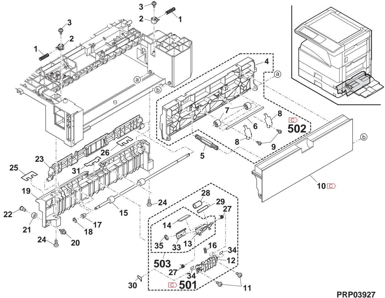
28 2e section d'entraînement (2nd drive section)
| NO. | PARTS CODE | Inter-changese | PRICE RANK | NEWMARK | PARTRANK | DESCRIPTION | TR No. | Effective time | |
| Ex. | Ja. | ||||||||
| 1 | PCOVP 0084QSZZ | AE | DJ | C | 2nd bottom cover | 2nd 底加- | |||
| 2 | CPWBF 0228QSE1 | AX | FG | E | 2nd cassette interface PWB | 2nd 加下中继基板 | |||
| 3 | XEBS730P08000 | AC | DD | C | Screw(3×8) | 6 | |||
| 4 | DHA i - 0597QSP1 | - | BF | GN | C | 2nd multi step harness | [Missing parts code] | 1st lot | |
| 5 | NBRGC0100FCZ1 | AC | DJ | C | Bearing 6 | 6 | |||
| 6 | MARMP 0018QSZZ | AD | DJ | C | Body joint arm | 本体連結7-4 | |||
| 7 | PCLC-0031QSZZ | - | AQ | EQ | B | 2nd paper feed clutch(42T) | [Missing parts code] | 1st lot | |
| 8 | XRESP40-06000 | AA | DD | C | E type ring(E4) | E リル* | |||
| 9 | XRESP50-06000 | AA | DD | C | E type ring(E5) | E リル* | |||
| 10 | MSPRT0203QSZZ | AC | DJ | C | Joint spring | 連結効力(42T) | |||
| 11 | NGERH0119QSZZ | AD | DJ | C | Gear(36T) | 6 | |||
| 12 | NGERH1207FCZZ | AF | DS | C | Joint gear(40T) | 連結効力 | |||
| 13 | CDA i U024RS58 | AZ | FQ | E | 2nd lift up unit | 2ndリフロー。 | |||
| 14 | XEBS740P30000 | AC | DD | C | Screw(4×30) | 6 | |||
| 15 | XEBS740P12000 | AA | DD | C | Screw(4×12) | 6 | |||
| 17 | DHA i - 0474QSP1 | - | BS | MW | C | LUM harness | LUM ルル | ||
| 20 | LPLTM0203QSZ1 | AF | DS | C | Multi step drive plate | 多段驅動効果 | |||
| 24 | NGERH0121QSZZ | AE | DJ | C | Gear(20T/45T/26P) | 6 | |||
| 25 | NBLTT029QSZZ | AG | DX | B | Vertical transport belt | 縄搬送効果 | |||
| 26 | PCLC-0020QSZZ | AX | FG | B | Transport clutch | 搬送効果 | |||
| 28 | NPLYZ0027QSZZ | AD | DJ | C | Vertical transport pulley | 縄搬送効果 | |||
| 29 | PSHEZ0250QSZZ | AB | DJ | C | Flange sheet | 万歳広ト | |||
| 30 | NROLP0008QSZZ | AD | DJ | C | Pulley | 7-1-1- | |||
| 31 | PSHEZ0249QSZZ | AB | DJ | C | Flange sheet | 万歳広ト | |||
| 32 | NBRGC0529FCZZ | AD | DJ | C | Bearing | 軸受 | |||
| 33 | LPLTM0176QSZ1 | AH | EB | C | Clutch earth plate | 万歳広ス板 | |||
| 34 | PSHEZ0556QSZZ | AC | DJ | C | Harness holder sheet | ハーマ�押元ト | |||
28 2e section d'entraînement (2nd drive section)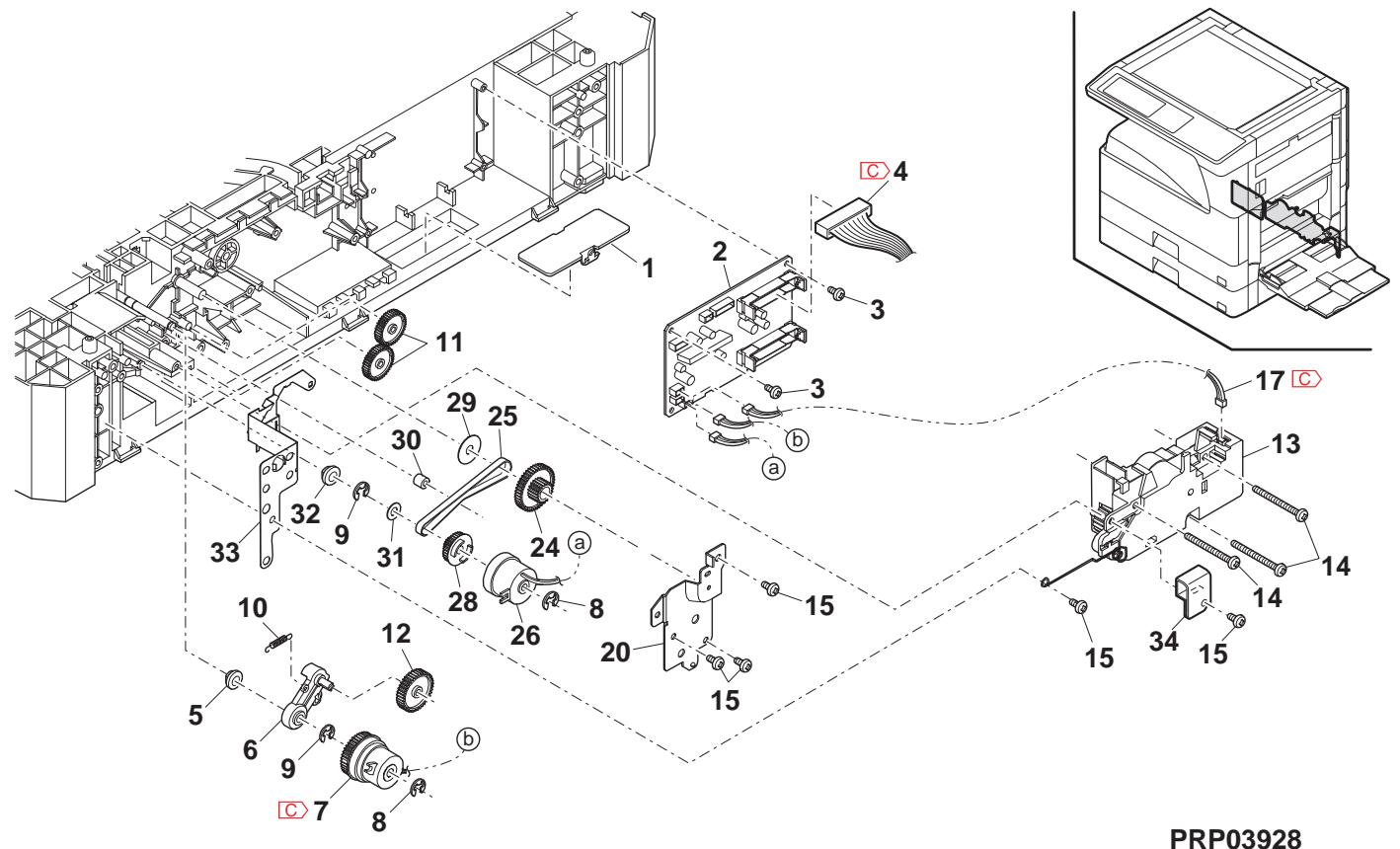
29 Unité de levage (Lift up unit) 29 Unité de levage (Lift up unit)
| NO. | PARTS CODE | Inter-changese | PRICE RANK | NEW MARK | PART RANK | DESCRIPTION | TR No. | Effective time | |
| Ex. | Ja. | ||||||||
| 1 | CMōTV 0 7 7 8 FCE 3 | AU | EZ | E | Lift up motor unit リフアフ" キーナー ハーナト | ||||
| 2 | NGERH0 1 5 8 QSZ 1 | AE | DJ | C | Gear(29T/11T) †* | ||||
| 3 | LDA i U 0 0 2 4 QSZ 2 | AF | DS | D | Lift up base リフアフ" キーナー | ||||
| 4 | NGERH0 1 0 2 QSZZ | AD | DJ | C | Gear(53T/14T) †* | ||||
| 5 | NSFTZ 0 0 4 5 QSZZ | AC | DJ | C | Shaft 沙フ | ||||
| 6 | NGERH0 1 0 3 QSZZ | AE | DJ | C | Gear(54T/13T) †* | ||||
| 7 | NSFTZ 0 0 4 4 QSZZ | AC | DJ | C | Shaft 沙フ | ||||
| 8 | NSFTZ 0 0 6 0 QSZZ | AC | DJ | C | Shaft 沙フ | ||||
| 9 | NGERH0 1 0 4 QSZZ | AE | DJ | C | Gear(13T/42T) †* | ||||
| 10 | NGERH0 1 0 5 QSZZ | AD | DJ | C | Gear(19T) †* | ||||
| 11 | PCOVP 0 0 6 1 QSZZ | AH | DS | D | Lift up cover リフアフ" 加"- | ||||
| 12 | MSPRD0 2 0 8 QSZZ | AC | DJ | C | 1st cassette earth spring 1st 加リフ-ス* リング* | ||||
| MSPRD0 2 5 1 QSZZ | AD | DJ | C | 2nd cassette earth spring 2nd 加リフ-ス* リング* | |||||
| 13 | MSPRC0 2 6 3 QSZZ | AC | DJ | C | Lift up spring リフアフ" キーナー* | ||||
| (Unit) | |||||||||
| 901 | CDA i U 0 0 2 4 RS 5 7 | AZ | FQ | E | 1st lift up unit 1st リフアフ" 加"- | ||||
| CDA i U 0 0 2 4 RS 5 8 | AZ | FQ | E | 2nd lift up unit 2nd リフアフ" 加"- | |||||
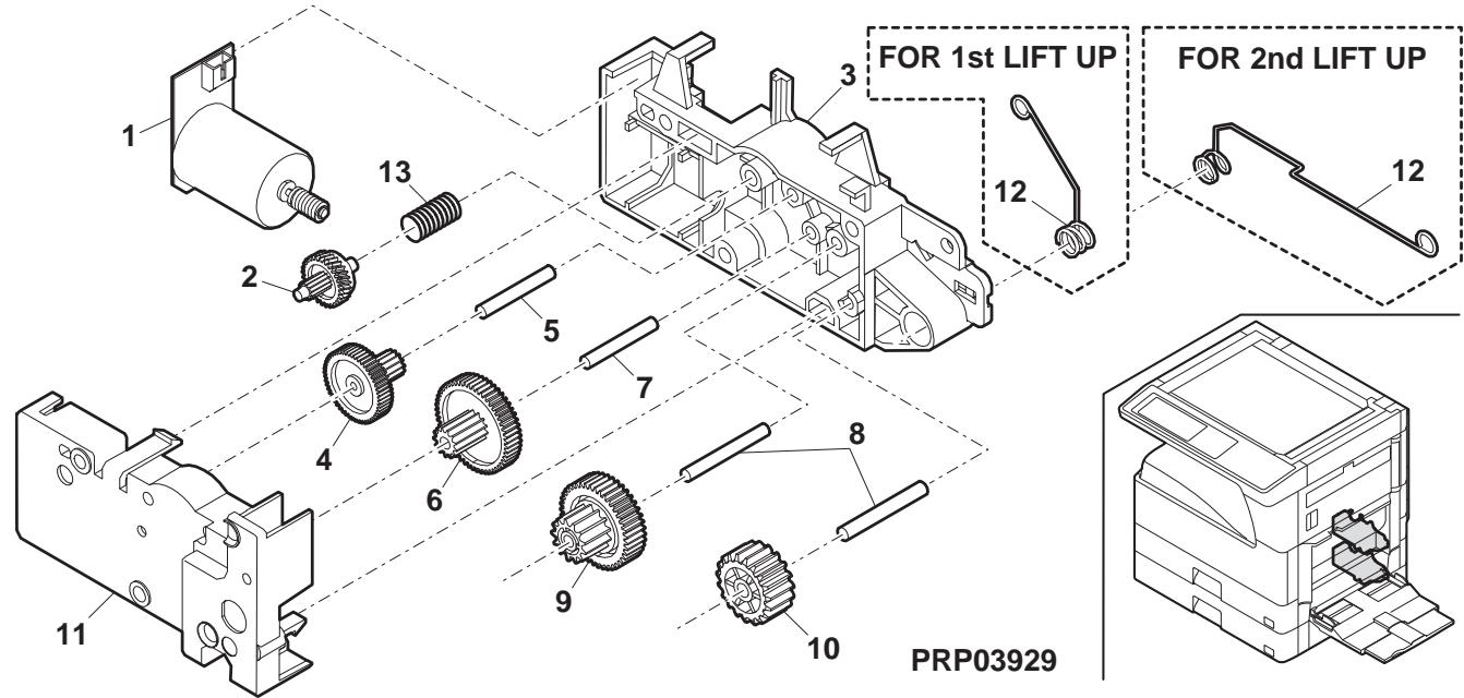
30 Extérieurs MX-RP10 1 (MX-RP10 Exteriors 1)
| NO. | PARTS CODE | Inter-chang | PRICE RANK | NEW MARK | PART RANK | DESCRIPTION | TR No. | Effective time | |
| Ex. | Ja. | ||||||||
| 1 | GCAB-0075QST1 | AR | EQ | D | Rear cabinet | 後枠を* | |||
| 2 | XEBS740P12000 | AA | DD | C | Screw(4×12) | ごλ | |||
| 3 | XHBS730P08000 | AB | DD | C | Screw(3×8) | ごλ | |||
| 4 | LSTPP0016QSZZ | AC | DJ | C | Stopper | LATAN- | |||
| 5 | PCLC-0023QSZZ | AS | EQ | B | SPF paper feed clutch | SPF給紙カーラー | |||
| 6 | NPLYZ0033QSZZ | AD | DJ | C | Coupling pulley(39P) | 加さリフロー- | |||
| 7 | CG i DM0106RS53 | - | BX | TF | E | SPF Transport unit [Missing parts code] | 搬送に換のRSPF | 1st lot | |
| 8 | XHBS730P10000 | AD | DD | C | Screw(3×10) | ごλ | |||
| 9 | GCAB-0074QST1 | AH | DX | D | Front cabinet | 前枠を* | |||
| 10 | MHNG-0021QSZZ | AX | FG | C | SPF hinge L | SPF フツジ L | |||
| 11 | MHNG-0022QSZZ | AX | FG | C | SPF hinge R | SPF フツジ R | |||
| 12 | XWVS740-05000 | AA | DD | C | Washer | ケラフロ | |||
| 13 | NBRGC0018QSZZ | AD | DJ | C | Bearing | 軸受 | |||
| 14 | LSOU-0037QST1 | BD | GJ | C | Base tray | へ-スレ | |||
| 15 | PCUSS0022QSZ3 | AW | EQ | C | OC mat | OC ナト | |||
| 16 | PSHEZ0413QSZZ | AD | DJ | C | OC mat sheet R | OC ナチト R | |||
| 17 | PSHEZ0077QSZ1 | AE | DJ | C | OC mat sheet F | OC ナチト F | |||
| 18 | XEBS730P08000 | AC | DD | C | Screw(3×8) | ごλ | |||
| 19 | LPLTP0321QSZZ | AE | DS | C | Width detect sensor fixing plate | 幅検知に換の取付板 | |||
| 20 | GCAB-0078QST1 | AV | FG | D | Original tray lower cabinet TLPD | 原種は下枠*TLPD | |||
| 21 | LSOU-0039QSZ1 | AN | EQ | C | Original tray S | 原種はS | |||
| 22 | MLEVP0098QSZZ | AC | DJ | C | Original detect actuator | 原種検知効効効力 | |||
| 23 | VHPGP1S73P+-18 | AF | DS | B | Photo sensor(GP1S73P) | 方は電気 | |||
| 24 | CPWBF0160QSE1 | AS | EQ | E | SPF VR PWB | SPF VR基板 | |||
| 25 | NGERP0168QSZZ | AD | DJ | C | Pinion gear(36T) | 幅検知に換の○円 | |||
| 26 | NGERR0169QSZZ | AE | DS | C | Width detect rack gear TLPD | 幅検知に換のTLPD | |||
| 27 | MSPRC0250QSZZ | AC | DJ | C | Tray lock spring | は亰はリフロー | |||
| 28 | PTME-0271FCZZ | AD | DJ | C | Tray lock pawl | は亰はリフロー | |||
| 29 | XEPS730P08X00 | AA | DD | C | Screw(3×8X) | ごλ | |||
| 30 | MSPRP0315QSZZ | AD | DJ | C | Regulation plate spring | 規制板状態 | |||
| 31 | LSOU-0038QST2 | AW | FG | C | Original tray TLPD | 原種はリフロー | |||
| 32 | LSOU-0041QST1 | AP | EQ | C | Middle tray TLPD | 中間はリフロー | |||
| 33 | LPLTP0319QSN1 | AG | DX | C | Regulation plate F TLPD | 規制板 F TLPD | |||
| 34 | LPLTP0320QSN1 | AG | DX | C | Regulation plate R TLPD | 規制板 R TLPD | |||
| 35 | DHA i-0468QSZZ | AH | DX | C | Original tray harness | 原種はリチロ | |||
| 37 | CCLEZ0020QS01 | AK | EB | C | SPF glass cleaner | SFP カスリフロー | |||
| 501 | CSOU-0037RS53 | CD | UD | E | Base tray unit(Include Block 31-501) | へ-スレはリフロー(フツル31-501含む) | |||
| 502 | CSOU-0038RS53 | CE | UH | E | Original tray unit | 原種はリチロ | |||
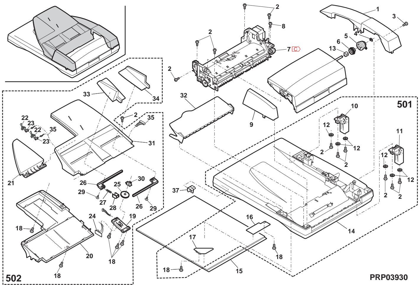
31 Extérieurs MX-RP10 2 (MX-RP10 Exteriors 2)
| NO. | PARTS CODE | Inter-chang | PRICE RANK | NEW MARK | PART RANK | DESCRIPTION | TR No. | Effective time | |
| Ex. | Ja. | ||||||||
| 1 | CPWBF 0139QSE1 | BA | FX | E | SPF interface PWB | SPF 中继基板 | |||
| 2 | XHBS730P08000 | AB | DD | C | Screw(3×8) | "λ" | |||
| 3 | DHA i-0448QSZZ | AV | FG | C | SPF interface harness | SPF 中继互换 | |||
| 4 | LPLTM0111QSZZ | AC | DJ | C | Reinforce plate earth plate | 補強板7-5板 | |||
| 5 | RPLU-0011QSZ2 | - | BA | FX | B | Gate solenoid [Missing parts code] | "[Missing parts code]" | 1st lot | |
| 6 | PSPO-0023QSZZ | AB | DJ | C | Sound proof sponge | 消音器"2" | |||
| 7 | PSPO-0004QSZZ | AB | DJ | C | Delivery gate sound proof sponge | 排纸"4" - " | |||
| 8 | RCORF0026FCZZ | AL | EB | C | Core(TRC-16813) | "7" | |||
| 9 | MSPRD0342QSZZ | AD | DJ | C | Delivery gate spring | 排纸"4" - " | |||
| 10 | MLEVP0036QSZZ | AD | DJ | C | Delivery gate lever | 排纸"4" - " | |||
| 11 | MLEVF0093QSZZ | AE | DJ | C | Pressure release lever | 压解"4" - | |||
| 12 | XBBS730P05000 | AA | DD | C | Screw(3×5) | "λ" | |||
| 13 | DHA i-0388QSPZ | AE | DS | C | Delivery sensor harness | 排纸"4" - " | |||
| 14 | MSPRD0211QSZZ | AC | DJ | C | Delivery sensor ACT spring | 排纸"4" - " | |||
| 15 | VHPSG2481+++1 | AE | DS | B | Photo sensor(SG2481) | "4" - " | |||
| 16 | MLEVP0092QSZZ | AC | DJ | C | Delivery sensor ACT lever TLPD | 排纸"4" - " | |||
| 17 | XRESP20-04000 | AA | DD | C | E type ring(E2) | "E" - " | |||
| 18 | NROLP0011QSZZ | AD | DJ | C | Delivery follower roller | 排纸 往動口 - " | |||
| 19 | PSPO-0020QSZZ | AB | DJ | C | Delivery sponge LPD | 蹬り出L" - "LPD" | |||
| 20 | PSHEZ0285QSZZ | AB | DJ | C | Delivery follower sound proof sheet | 排纸 往動 消音子插 | |||
| 21 | NSFTZ0013QSP1 | AF | DJ | C | Delivery sub shaft | 排纸 往動軸 | |||
| 22 | PSPO-0003QSZZ | AC | DJ | C | Sound proof sponge | 消音器"2" | |||
| 23 | LHLDZ0101QSZZ | AE | DS | C | Pressure release holder | 压解"4" - | |||
| LHLDZ0101QSZ1 | 1 | AE | DJ | C | Pressure release holder | 压解"4" - | 09/12 | ||
| 24 | MSPRD0305QSZZ | AC | DJ | C | Delivery sub spring | 排纸 往動 λ" - " | |||
| 25 | LPiNSO327FCZZ | AC | DJ | C | SP pin(2×10) | SP" - " | |||
| 26 | NSFTZ0072QSZZ | - | AN | EQ | C | Pressure release shaft TLPD | [Missing parts code] 压解轴 TLPD | 1st lot | |
| 27 | XRESP50-06000 | AA | DD | C | E type ring(E5) | "E" - " | |||
| 28 | NBRGM0501FCZZ | AB | DJ | C | Bearing | 轴承 | |||
| 29 | NSFTZ0009QSP1 | AE | DJ | C | Transport sub shaft | 搬送従動軸 | |||
| 30 | NROLP1517FCZZ | AA | DJ | B | Transport sub roller | 搬送 往動口 - " | |||
| 31 | MSPRP0306QSZZ | AC | DJ | C | Read front sub spring | 請取前従動 λ" - " | |||
| 32 | LPLTM0316QSZZ | AH | DX | C | Base tray reinforce plate | "-" - "補強板" | |||
| 33 | XEBS730P08000 | AC | DD | C | Screw(3×8) | "λ" | |||
| 34 | MSPRC0307QSZ1 | AC | DJ | C | Read front follower earth spring | 請取前従動7-λ" - " λ" - " | |||
| 35 | MSPRP0123QSZZ | AD | DJ | C | Transport sub spring | 搬送 往動 λ" - " | |||
| 36 | MSPRT0308QSZZ | AC | DJ | C | Delivery sub earth spring | 排纸 往動7-λ" - " λ" - " | |||
| 37 | PSHEZ0436QSZZ | AD | DJ | C | Read front sheet | 請取前ト | |||
| 38 | PSHEZ0069QSZZ | AE | DJ | C | Base tray sheet | "-" - "補強板" | |||
| 39 | PSHEZ0439QSZ1 | AD | DJ | C | Delivery gate sheet | 排纸"4" - "LDP" | |||
| 40 | LPLTP0117QSZZ | AM | EG | C | Delivery gate | 排纸"4" - " | |||
| 41 | NBRGP0041GCZZ | AD | DJ | C | Bearing | 轴承 | |||
| 42 | PRNGP0090FCZ1 | AB | DJ | C | Resin E ring(E5) | 樹脂 E" - " | |||
| 43 | LSOU-0037QST1 | BD | GJ | C | Base tray TLPD | "-" - "TLPD" | |||
| 44 | PSHEZ0459QSZZ | AC | DJ | C | Delivery gate sheet lower | 排纸"4" - "LDP" 下 | |||
| 501 | CSOU-0037RS53 | CD | UD | E | Base tray unit(Include Block 30-501) | "-" - "補強板" ( "[7" - "30-501 含む)" ) | |||
31 Extérieurs MX-RP10 2 (MX-RP10 Exteriors 2)
32 Section d'alimentation papier MX-RP10 (MX-RP10 Paper feeding section)
| NO. | PARTS CODE | Inter-chang | PRICE RANK | NEW MARK | PART RANK | DESCRIPTION | TR No. | Effective time | ||||||||||
| Ex. | Ja. | |||||||||||||||||
| 1 | GCAB-0076QST1 | AN | EG | D | Open/close cabinet | 開閉掛+ | ||||||||||||
| 2 | NGERH0166QSZZ | AC | DJ | C | Paper feed shaft gear(20T) | 給紙軸挂+ | ||||||||||||
| 3 | PCLC-0316FCP1 | AP | EQ | B | Torque limiter | トクルーヤー | ||||||||||||
| 4 | MLNKP0001QSZZ | AD | DJ | C | Pick up link TLPD | 呼営みりLTPD | ||||||||||||
| 5 | MSPRD0309QSZZ | AC | DJ | C | Pick up arm spring | 呼営みりムスリ+ | ||||||||||||
| 6 | NGERH0167QSZZ | AD | DJ | C | Paper feed drive gear(32T) | 給紙驅動掛+ | ||||||||||||
| 7 | NBRGM0096FCZ1 | AC | DJ | C | Bearing | 軸受 | ||||||||||||
| 9 | XRESP50-06000 | AA | DD | C | E type ring(E5) | E リ+ | ||||||||||||
| 10 | NSFTB0075QSZ1 | - | AF | EG | C | Paper feed roller shaft [Missing parts code] | 絵紙ローツ軸 | |||||||||||
| 11 | XPSSP20-07000 | AA | DD | C | Spring pin(φ2-7) | λ" リリ+"" ビ+ | ||||||||||||
| 12 | LPLTM0318QSZZ | AC | DJ | C | Paper feed earth plate | 給紙7-板 | ||||||||||||
| 13 | XEBS730P08000 | AC | DD | C | Screw(3×8) | b+ | ||||||||||||
| 14 | MSPRD0314QSZZ | AD | DJ | C | JAM release spring R TLPD | JAM 解除λ" リリ+R TLPD | ||||||||||||
| 15 | NSFTZ0074QSZ2 | - | AM | EB | C | Paper feed shaft [Missing parts code] | 給紙入力軸 | |||||||||||
| 17 | NBRGCO018QSZZ | AD | DJ | C | Bearing(φ8) | 軸受 | ||||||||||||
| 18 | NPLYZ0033QSZZ | AD | DJ | C | Coupling pulley(39P) | 加熱の効力+ | ||||||||||||
| 19 | PCLC-0023QSZZ | AS | EQ | B | SPF paper feed clutch | SPF給紙状態 | ||||||||||||
| 20 | MARMM0047QSZZ | AE | DJ | C | U-turn paper guide arm R | U 样-大-大+大+大+大+大+大+大+大+大+大+大+大+大+大+大+大+大+大+大+大+大+大+大+大+大+大+大+大+大+大+大+大+大+大+大+大+大+大+大+大+大+大+大+大+大+大+大+大+大+大+大 +大+大+大+大+大+大+大+大+大+大+大+大+大+大+大+大+大+大+大+大+大+大+大+大+大+大+大+大+大+大+大+大+大+大+大+大+大+大+大+大+大+大+大+大+大+大+大+大+大+大=大+大+大+大+大+大+大+大+大+大+大+大+大+大+大+大+大+大+大+大+大+大+大+大+大+大+大+大+大+大+大+大+大+大+大+大+大+大+大+大+大+大+大+大+大+大+大+大+大+大 | ||||||||||||
| 21 | LSTPP0016QSZZ | AC | DJ | C | Resin E ring(E5) | 樹脂 E リ�+ | ||||||||||||
| 22 | DHA i-0390QSZZ | AC | DJ | C | U-turn earth harness | U 样-大-大-大-大-大-大-大-大-大-大-大-大-大-大-大-大-大-大-大-大-大-大-大-大-大-大-大-大-大-大-大-大-大-大-大-大-大-大-大-大-大-大-大-大-大-大-大-大-大-大- | 1st lot | |||||||||||
| 23 | PG i DM0105QSZ1 | AQ | EQ | C | U-turn paper guide TLPD | U 样-大-大-大-大-大-大-大-大-大-大-大-大-大-大-大-大-大-大-大-大-大-大-大-大-大-大-大-大-大-大-大-大-大-大-大-大-大-大-大-大-大-大-大-大-大-大-大- | 1st lot 1st lot | |||||||||||
| 24 | GCAB-0077QST1 | AP | EQ | D | U-turn paper guide cabinet | U 样-大-大-大-大-大-大-大-大-大-大-大-大-大-大-大-大-大-大-大-大-大-大-大-大-大-大-大-大-大-大-大-大-大-大-大-大-大-大-大-大-大-大-大-大-大-大-大- | ||||||||||||
| 26 | MSPRP0311QSZZ | AC | DJ | C | PS sub tension spring | PS 從動 テクタク矢+” ビ+ | ||||||||||||
| 27 | PTME-0029QST1 | AE | DJ | C | U-turn paper guide lock pawl TLPD | U 样-大-大-大-大-大-大-大-大-大-大-大-大-大-大-大-大-大-大-大-大-大-大-大-大-大-大-大-大-大-大-大-大-大-大-大-大-大-大-大-大-大-大-大-大-大-大 -大-大-大-大-大-大-大-大-大-大-大-大-大-大-大-大-大-大-大-大-大-大-大-大-大-大-大-大-大-大-大-大-大-大-大-大-大-大-大-大-大-大-大-大-大-大-大-大-大-大 -大-大-大- | ||||||||||||
| 28 | MSPRD0310QSZZ | AC | DJ | C | U-turn paper guide lock spring TLPD | U 样-大-大-大-大-大-大-大-大-大-大-大-大-大-大-大-大-大-大-大-大-大-大-大-大-大-大-大-大-大-大-大-大-大-大-大-大-大-大-大-大-大-大-大-大-大-大 | 29 | NROLP1517FCZZ | AA | DJ | B | Transport sub roller | 搬送徴動広- | |||||
| 30 | NSFTZ0009QSP1 | AE | DJ | C | Transport sub shaft | 搬送徴動軸 | ||||||||||||
| 31 | MARMP0046QSZZ | AD | DJ | C | U-turn paper guide arm F | U 样-大-大-大-大-大-大-大-大-大-大-大-大-大-大-大-大-大-大-大-大-大-大-大-大-大-大-大-大-大-大-大-大-大-大-大-大-大-大-大-大-大-大-大-大-大-大-大-中 -大-F | ||||||||||||
| 32 | PCOVP0094QSZZ | AD | DJ | C | Maintenance cover | ルフロー+ | ||||||||||||
| 33 | PCOVP0094QSZ1 | 1 | AD | DJ | C | Maintenance cover | ルフロー+ | |||||||||||
| 34 | CSFTB0073QS01 | AF | DS | E | Pick up roller shaft ASS'Y | 搬送徴動広- | ||||||||||||
| 35 | MARMP0044QSZ1 | AF | DS | C | Pick up arm | 呼営みりローツ軸 | ||||||||||||
| 36 | LFRM-0069QSZ1 | AQ | EQ | C | Paper feed frame TLPD | 給紙ルフロー+ | ||||||||||||
| 37 | LFRM-0069QSZ2 | 1 | AQ | EQ | C | Paper feed frame TLPD | 給紙ルフロー+ | |||||||||||
| 38 | NCPL-0049FCBZ | AT | EZ | C | 1way coupling | 1 way 加工+ | ||||||||||||
| 39 | NPLYZ0035QSZZ | AD | DJ | C | Paper feed roller pulley(16P) | 給紙ローツ+ | ||||||||||||
| 39 | NROLR0166QSZZ | - | AX | FG | B | Paper feed roller [Missing parts code] | 給紙ローツ+ | |||||||||||
| 40 | NROLR1542FCZZ | AH | DX | B | Pick up roller | 呼営みりローツ+ | ||||||||||||
| 41 | NPLYZ0034QSZZ | AD | DJ | C | Pick up roller pulley(16P) | 呼営みりローツ+ | ||||||||||||
| 42 | NBLTT0033QSZZ | AF | DS | B | Drive belt | 驱动+大+小 | ||||||||||||
| 43 | VHPGP1S73P+-18 | AF | DS | B | Photo sensor(GP1S73P) | 才はこ+一 | ||||||||||||
| 44 | DHA i-0469QSZZ | AG | DX | C | Paper feed unit harness | 給紙ルフロー+ | ||||||||||||
| 45 | PSHEZ0444QSZZ | AE | DS | C | Pick up sheet | 呼営みりローツ+ | ||||||||||||
| 46 | MLEVP0097QSZZ | AC | DJ | C | Original detect actuator | 原稿核知 予法必予+ | ||||||||||||
| 47 | LSTPP0015QSZZ | AC | DJ | C | Stopper | 才はこ+ | ||||||||||||
| 48 | MLEVP0096QSZZ | AC | DJ | C | Stopper release lever | 才はこ+解除+ | ||||||||||||
| 49 | MARMP0045QSZZ | AC | DJ | C | Stopper arm | 才はこ+一 | ||||||||||||
| 50 | MSPRD0313QSZZ | AC | DJ | C | JAM release spring F | JAM 解除 λ" ビ+ | ||||||||||||
| 51 | PSHEZ0407QSZZ | AB | DJ | C | PS guide sheet | PS 加工+一 | ||||||||||||
| 52 | VHPSG2481++--1 | AE | DS | B | Photo sensor(SG2481) | 才はこ+ | ||||||||||||
| 53 | LHLDZ0153QSZZ | AC | DJ | C | SPF pick up sub holder | SPF 呼営み�+補助株+ | ||||||||||||
| 54 | PMLT-0095QSZZ | AB | DJ | C | Pick up arm cushion | 呼営みりローツ+ | ||||||||||||
| 501 | CCAB-0077RS53 | BP | LP | E | U-turn paper guide unit | U 样-大-大-大-大-大-大-大-大-大-大-大-大-大-大-大-大-大-大-大-大-大-大-大-大-大-大-大-大-大-大-大-大-大-大-大-大-大-大-大-大-大-大-大-大-大-大-大-一 | ||||||||||||
32 Section d'alimentation papier MX-RP10 (MX-RP10 Paper feeding section)
33 Section de transport MX-RP10 1 (MX-RP10 Transport section 1)
| NO. | PARTS CODE | Inter-chang | PRICE RANK | NEW MARK | PART RANK | DESCRIPTION | TR No. | Effective time | |
| Ex. | Ja. | ||||||||
| 1 | PG i DM0 107QSZ1 | AQ | EQ | C | Paper feed guide 結紙がつ | ||||
| 2 | PSHEZ0452QSZZ | AF | DS | C | Front separator sheet 前削きつ | ||||
| 4 | PSHEZ0423QSZZ | AP | EQ | C | Separator sheet 括きつ | ||||
| 5 | LPLTP0328QSZZ | AC | DJ | C | SPF separator plate SPF 括きつ板 | ||||
| 6 | MSPRC0321QSZ1 | AB | DJ | C | Pressure spring 压力λリル | ||||
| 7 | PSHEZ0451QSZZ | AC | DJ | C | Sound proof sheet 前削き消音つ | ||||
| 9 | LPLTM0327QSZZ | AD | DJ | C | Sound proof plate 消音板 | ||||
| 11 | XHBS730P08000 | AB | DD | C | Screw(3×8) ヒλ | ||||
| 12 | NROLR0096QSZZ | AR | EQ | B | Transport roller 搬送ローナ- | ||||
| 13 | NRRLR0131QSZZ | AP | EQ | B | PS roller SPF PS 0-5-SPF | ||||
| 14 | NRRLR0095QSZZ | AR | EQ | B | Read front roller 識取前ローナ- | ||||
| 15 | PSHEP0647QSZZ | AD | DJ | C | White sheet AN2R 白円円-AN2R | ||||
| 16 | LPLTM0325QSZZ | AH | DX | C | Transport plate 搬送板 | ||||
| 17 | MSPRC0360QSZZ | AC | DJ | C | Delivery paper guide spring R 掺紙がつ" ヒリル" R | ||||
| 18 | DHA i -0467QSZZ | AP | EQ | C | RSPF harness RSPF ハス | ||||
| 19 | RDTCT0006QSPZ | AX | FG | B | Paper feed in detect sensor 入紙検知址表 | ||||
| 20 | PTME-0030QSZZ | AC | DJ | C | Open/close lock pawl TLPD 开閉ローナ爪 TLPD | ||||
| 21 | MSPRC3356FCZZ | AA | DJ | C | Lock spring ハリル" R | ||||
| 22 | NBGRM0501FCZZ | AB | DJ | C | Bearing 輸受 | ||||
| 23 | XRESP50-06000 | AA | DD | C | E type ring(E5) E ヒル" | ||||
| 24 | XPSSP20-09000 | AA | DD | C | Spring pin(φ2-9) フリル" F | ||||
| 25 | NPLYZ0019QSZZ | AE | DJ | C | PS pulley PS フリル" | ||||
| 26 | PSHEP3029FCZZ | AA | DD | C | Flange sheet DUP2 万円円-トZIP2 | ||||
| 27 | LHLDZ0102QSZ1 | AC | DJ | C | Tension holder F ヱンクル" F | ||||
| 28 | XEBS730P08000 | AC | DD | C | Screw(3×8) ヒλ | ||||
| 29 | NKOM-0007QSZZ | AC | DJ | C | Tension roller フリル" R | ||||
| 30 | MLEVPP0095QSZZ | AD | DJ | C | Book sensor actuator TLPD フリル" R-万円円-トLPD | ||||
| 32 | VHPSG2481++--1 | AE | DS | B | Photo sensor(SG2481) フリル" | ||||
| 33 | XEBS740P14000 | AB | DD | C | Screw(4×14) フリス | ||||
| 34 | MSPRC0153QSZZ | AB | DJ | C | Book sensor spring フリル" R-万円円" | ||||
| 35 | XWVS740-05000 | AA | DD | C | Washer ハリル" | ||||
| 36 | LPLTP0434QSZZ | AC | DJ | C | Book sensor fixing plate B1A 取付板 B1A | ||||
| 37 | JKNBZ0009QSZZ | AE | DJ | D | JAM release knob(24P) JAM 解除/7 | ||||
| 38 | NBLTT0036QSZZ | AF | DS | B | Belt(B79MXL4.0) フリル" | ||||
| 39 | NBRGC0017QSZZ | AC | DJ | C | Bearing 軸受 | ||||
| 40 | MSPRD0316QSZZ | AC | DJ | C | Tension spring F フリル" R-万円円" F | ||||
| 41 | LPLTP0324QSZZ | AH | DX | C | Revers gate plate 反転凹-板 | ||||
| 42 | NROLR0097QSZZ | AR | EQ | B | Delivery paper roller 掺紙に一 | ||||
| 43 | LPLTM0326QSZZ | AM | EG | C | Paper feed paper guide reinforce plate 紹紙 ハリル"補強板 | ||||
| 44 | PBRSS0008QSZ1 | AH | DX | B | Discharge brush 除電アリ | ||||
| 45 | PG i DM0106QSZ1 | AU | EZ | C | Transport R paper guide 搬送R ハリル" R | ||||
| 46 | PSHEZ0454QSZZ | AB | DJ | C | Paper feed paper guide cushion R 紹紙 ハリル" R-万円" | ||||
| 47 | PSHEZ0455QSZZ | AD | DJ | C | Paper feed paper guide sound proof cushion 紹紙 ハリル" 消音圧圧 | ||||
| 48 | MSPRC0063QSZZ | AB | DJ | C | Delivery paper guide spring 掺紙 ハリル"補強板 | ||||
| 49 | LX-WZ5002BCZZ | AA | DD | C | Poly slider(6,2-12-0.5) フリル" | ||||
| 501 | CG i DM0106RS53 | - | BX | TF | E | SPF Transport unit [Missing parts code] 搬送工料RSPF (700円34-501含む。No.18 除く) | 1st lot | ||
33 Section de transport MX-RP10 1 (MX-RP10 Transport section 1)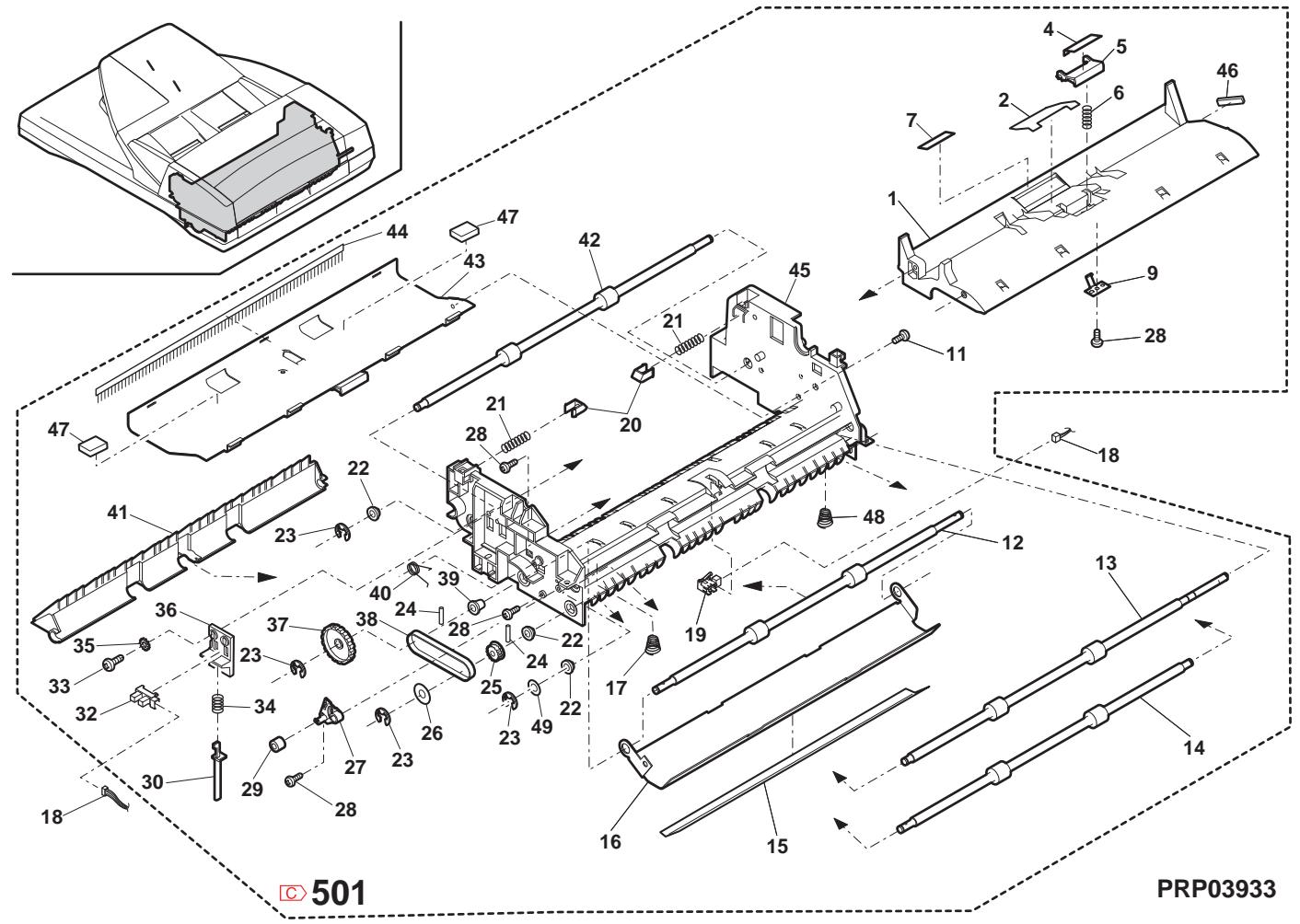
34 Section de transport MX-RP10 2 (MX-RP10 Transport section 2)
| NO. | PARTS CODE | Inter-chang | PRICE RANK | NEW MARK | PART RANK | DESCRIPTION | TR No. | Effective time | |
| Ex. | Ja. | ||||||||
| 1 | RMOT50043QSPZ | BG | GT | B | SPF motor TLPD | SPF フロー TLPD | |||
| 2 | DHA i - 0467QSZZ | AP | EQ | C | RSPF harness | RSPF ハーニ | |||
| 3 | PTE-0018QSZZ | AC | DJ | C | Motor earth tape | モーナー・デー・デー・ | |||
| 4 | XEBS730P08000 | AC | DD | C | Screw(3×8) | "λ" | |||
| 6 | RPLU-0015QSP1 | AR | EQ | B | Pressure release solenoid | 压解体/片" | |||
| 7 | PSPO-0022QSZZ | AB | DJ | C | Sound proof sponge | 消音体" | |||
| 8 | XRESP40-06000 | AA | DD | C | E type ring(E4) | E"ル" | |||
| 9 | PSHEZ0414QSZZ | AB | DJ | C | Flange sheet | 万能"ト | |||
| 10 | NBLTT0034QSZZ | AF | DS | B | Belt(48S2M244) | "応"板 | |||
| 11 | NGERH0170QSZZ | AD | DJ | C | Gear(48T/43P) | "さ"板 | |||
| 12 | NBRGM0501FCZZ | AB | DJ | C | Bearing | 軸受 | |||
| 13 | NGERH0116QSZ1 | AD | DJ | C | Gear(48T/25P) | "さ"板 | |||
| 14 | XEPS730P08X00 | AA | DD | C | Screw(3×8X) | "さ"板 | |||
| 15 | NGERH0117QSZZ | AK | DX | C | Gear(48T) | "さ"板 | |||
| 16 | XPSSP20-09000 | AA | DD | C | Spring pin(φ2-9) | 万能"リフ"板 | |||
| 17 | NPLYZ0019QSZZ | AE | DJ | C | PS pulley | PS "さ"-リ卜 | |||
| 18 | NBLTT0035QSZZ | AE | DS | B | Belt(B86MXL4.0) | "さ"板 | |||
| 19 | PSHEP3029FCZZ | AA | DD | C | Flange sheet(DUP2) | 万能"ロト | |||
| 20 | XRESP50-06000 | AA | DD | C | E type ring(E5) | E"ル"板 | |||
| 21 | MSPRP0312QSZZ | AD | DJ | C | U-turn earth spring | U形角 万能"リフ"板 | |||
| 22 | XHBS730P08000 | AB | DD | C | Screw(3×8) | "さ"板 | |||
| 23 | NBRGC0017QSZZ | AC | DJ | C | Bearing | 軸受 | |||
| 24 | NPLYZ0018QSZZ | AE | DJ | C | PS coupling pulley | PS "さ"-リフ"板"一"一" | |||
| 25 | PCLC-0032QSZZ | AX | FG | B | PS clutch SPF | PS "さ"-SPF | |||
| 26 | NKOM-0007QSZZ | AC | DJ | C | Tension roller | アーニングロド | |||
| 27 | MSPRT0317QSZZ | AC | DJ | C | Tension spring R | テ�ーニングロフ"R | |||
| 28 | LHLDZ0103QSZZ | AC | DJ | C | Tension holder R | テ�ーニングロフ"R | |||
| 29 | LPLTM0322QSZZ | AF | DS | C | Transport earth plate | 搬送アス板 | |||
| 31 | LPLTM0323QSZ1 | AG | DX | C | Motor fixing plate | "さ"-取付板 | |||
| 32 | XBBS730P05000 | AA | DD | C | Screw(3×5) | "さ"板 | |||
| 34 | MSPRC0418QSZZ | AC | DJ | C | PS Brake spring AN2R | PS "さ"-万能"AN2R | |||
| 35 | XWHS760-08115 | AA | DD | C | Washer(M6) | 万能"一" | |||
| 37 | PTPE-0069QSZZ | AC | DJ | C | SPF motor cooling sheet | SPF フロー放熱ロト | |||
| 38 | LX-WZ5002BCZZ | AA | DD | C | Poly slider(6.2-12-0.5) | "さ"-ロフ"一" | |||
| 501 | CG i DM0106RS53 | - | BX | TF | E | SPF Transport unit(Include Block 33-501)[Missing parts code] | 搬送工号RSPF(70円33-501含む) | 1st lot | |
34 MX-RP10 搬送部 2 (MX-RP10 Transport section 2)
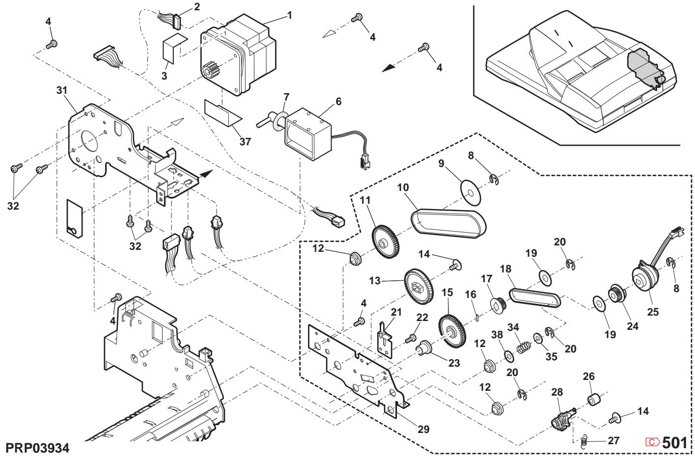
35 MX-TR11 第二排紙 (MX-TR11 2nd delivery paper unit)
| NO. | PARTS CODE | Inter-changese | PRICE RANK | NEW MARK | PART RANK | DESCRIPTION | TR No. | Effective time | ||
| Ex. | Ja. | |||||||||
| 1 | XHBS740P10000 | AA | DD | C | Screw(4×10) | 匕'ス | ||||
| 2 | CPLTM0216QS01 | AH | DX | C | DID rail sub plate | DID lever 補助7"レト | ||||
| CPLTM0216QS02 | 1 | AH | DX | C | DID rail sub plate | DID lever 補助7"レト | 09/08 Mid | |||
| 3 | PBRSR0021QSZ1 | AG | DS | B | Discharger brush S | 除電7"ロス | ||||
| 4 | PBRSR0020QSZ1 | AH | DX | B | Discharger brush L | 除電7"ロスL | ||||
| 5 | LFRM-0047QSZZ | AG | DX | D | Delivery frame | 排紙7"レム | ||||
| 6 | LFRM-0058QSZ1 | AG | DX | D | Delivery frame R | 排紙7"レムR | ||||
| 7 | MSPRT0229GCAZ | AC | DJ | C | FU spring R | FU7"リフR | ||||
| 8 | NROLP1122FCZZ | AF | DS | C | PS upper roller | PS上ローナ | ||||
| 9 | NROLR0056QSZ1 | AN | EQ | C | Delivery roller | 排紙7"レーロ | ||||
| 10 | DHA i-0592QSPZ | AH | DX | C | 2nd delivery harness | 2nd排紙ハネ | ||||
| 11 | MSPRD0218QSZ1 | AE | DS | C | Delivery earth spring | 排紙7"ス7"リル | ||||
| 12 | VHPGP1SQ44S-18 | AK | EB | B | Photo sensor(GP1SQ44S) | 7thtantle | ||||
| 13 | VHPGP1SQ73P-18 | AF | DS | B | Photo sensor(GP1SQ73P) | 7thtantle | ||||
| 15 | QSW-B0017QSZ | AF | DS | B | Tray detect switch | トレ検知スリツ | ||||
| 16 | NBRGM0501FCZZ | AB | DJ | C | Bearing | 軸受 | ||||
| 17 | NGERH0111QSZ | AC | DJ | C | Drive gear A(25T) | 驱动7"7A | ||||
| 18 | NGERH0110QSZ | AE | DJ | C | Idle gear A(29T) | 7tht"7"A | ||||
| 19 | NGERH0112QSZ | AC | DJ | C | Drive gear B(25T) | 驱动7"7B | ||||
| 20 | NBRGY2122SCZZ | AB | DD | C | Transport roller bearing | 搬送ローナ轴受 | ||||
| 21 | PGiDM0164QSZ | AQ | EQ | C | Delivery lower paper guide | 排紙下 7"一"7"7"7"7"7"7"7"7"7"7"7"7"7"7"7"7"7"7"7"7"7"7"7"7"7"7"7"7"7"7"7"7"7"7"7"7"7"7"7"7"7"7"7"7"7"7"7"7"7"7" | ||||
| 22 | NROLR0051QSZ1 | AL | EB | C | DUP delivery roller | DUP排紙7"7"7"7"7"7"7"7"7"7"7"7"7"7"7"7"7"7"7"7"7"7"7"7"7"7"7"7"7"7"7"7"7"7"7"7"7"7"7"7"7"7"7"7"7"7"7"7"7"7' | ||||
| 23 | LBSHZ0303FCZZ | AC | DJ | C | M bushing C | M7"7"7"7"7"7"7"7"7"7"7"7"7"7"7"7"7"7"7"7"7"7"7"7"7"7"7"7"7"7"7"7"7"7"7"7"7"7"7"7"7"7"7"7"7"7"7"7"7"7 " | ||||
| 24 | XRESP40-06000 | AA | DD | C | E type ring(E4) | E7"7"7"7"7"7"7"7"7"7"7"7"7"7"7"7"7"7"7"7"7"7"7"7"7"7"7"7"7"7"7"7"7"7"7"7"7"7"7"7"7"7"7"7"7"7"7"7"7"7” | ||||
| 25 | MLEVP0067QSZ2 | AD | DJ | C | Delivery actuator | 排紙7"7"7"7"7"7"7"7"7"7"7"7"7"7"7"7"7"7"7"7"7"7"7"7"7"7"7"7"7"7"7"7"7"7"7"7"7"7"7"7"7"7"7"7"7"7"7"7"7' | ||||
| 26 | XRESP50-06000 | AA | DD | C | E type ring(E5) | E7"7"7"7"7"7"7"7"7"7"7"7"7"7"7"7"7"7"7"7"7"7"7"7"7"7"7"7"7"7"7"7"7"7"7"7"7"7"7"7"7"7"7"7"7"7"7"7" | ||||
| 27 | XHBS730P08000 | AB | DD | C | Screw(3×8) | 7"7" | ||||
| 28 | XHBS740P10000 | AA | DD | C | Screw(4×10) | 7"7" | ||||
| 29 | NSFTZ0117QSZ | AE | DS | C | Joint idle shaft | 連結7"7"7"7"7"7"7"7"7"7"7"7"7"7"7"7"7"7"7"7"7"7"7"7"7"7"7"7"7"7"7"7"7"7"7"7"7"7"7"7"7"7"7"7"7"7"7"7"7"7 連結7"7"7"7"7"7"7"7"7"7"7"7"7"7"7"7"7"7"7"7"7"7"7"7"7"7"7"7"7"7"7"7"7"7"7"7"7"7"7"7"7"7"7"7"7"7"7"7"7 连结7"7"7"7"7"7"7"7"7"7"7"7"7"7"7"7"7"7"7"7"7"7"7"7"7"7"7"7"7"7"7"7"7"7"7"7"7"7"7"7"7"7"7"7"7"7"7"7"7"7" 连结7"7"7"7"7"7"7"7"7"7"7"7"7"7"7"7"7"7"7"7"7"7"7"7"7"7"7"7"7"7"7"7"7"7"7"7"7"7"7"7"7"7"7"7"7"7"7"7"7 连結7"7"7"7"7"7"7"7"7"7"7"7"7"7"7"7"7"7"7"7"7"7"7"7"7"7"7"7"7"7"7"7"7"7"7"7"7"7"7"7"7"7"7"7"7"7"7"7"7" | ||||
| 30 | PCLR-0015QSZ | AC | DJ | C | 21 collar | 2145 | ||||
| 31 | NGERH0230QSZ | AC | DJ | C | Gear(21T) | 9"7" | ||||
| 32 | XBPS740P08KS0 | AB | DD | C | Screw(4×8KS) | 9"7" | ||||
| 33 | PSHEP0660QSZZ | - | AB | DJ | C | Harness protect sheet | [Missing parts code] トレ検保護マリア- | 1st lot | ||
| (Unit) | ||||||||||
| 901 | CG i DM0164RS51 | - | BC | GJ | E | 2nd delivery unit(Without No.28) [Missing parts code] 2nd排紙100- (No.28除<) | 1st lot | |||
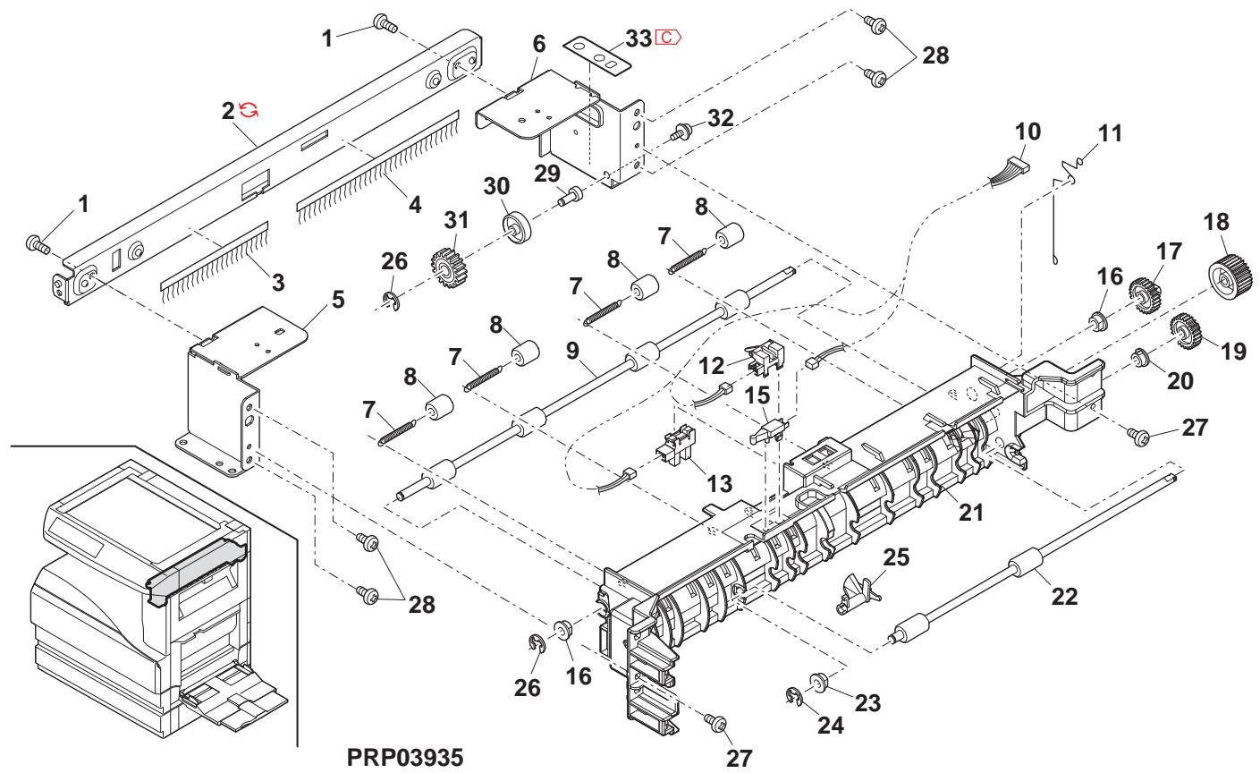
36 MX-TR11 ヨフハレーダーニット (MX-TR11 Job-separator unit)
| NO. | PARTS CODE | Inter-changese | PRICE RANK | NEWMARK | PARTRANK | DESCRIPTION | TR No. | Effective time | |
| Ex. | Ja. | ||||||||
| 1 | LCLOU-0034QST3 | - | AY | FQ | D | 2nd delivery tray [Missing parts code] 2nd排紙紙 | 1st lot | ||
| 2 | GCOV-0042QST1 | AK | DX | D | Rail dummy cover レーナス ハン- | ||||
| 3 | MLEVP006QSZZ | AD | DJ | C | Actuator しぃけり | ||||
| 4 | XEBS730P08000 | AC | DD | C | Screw(3×8) ご*λ | ||||
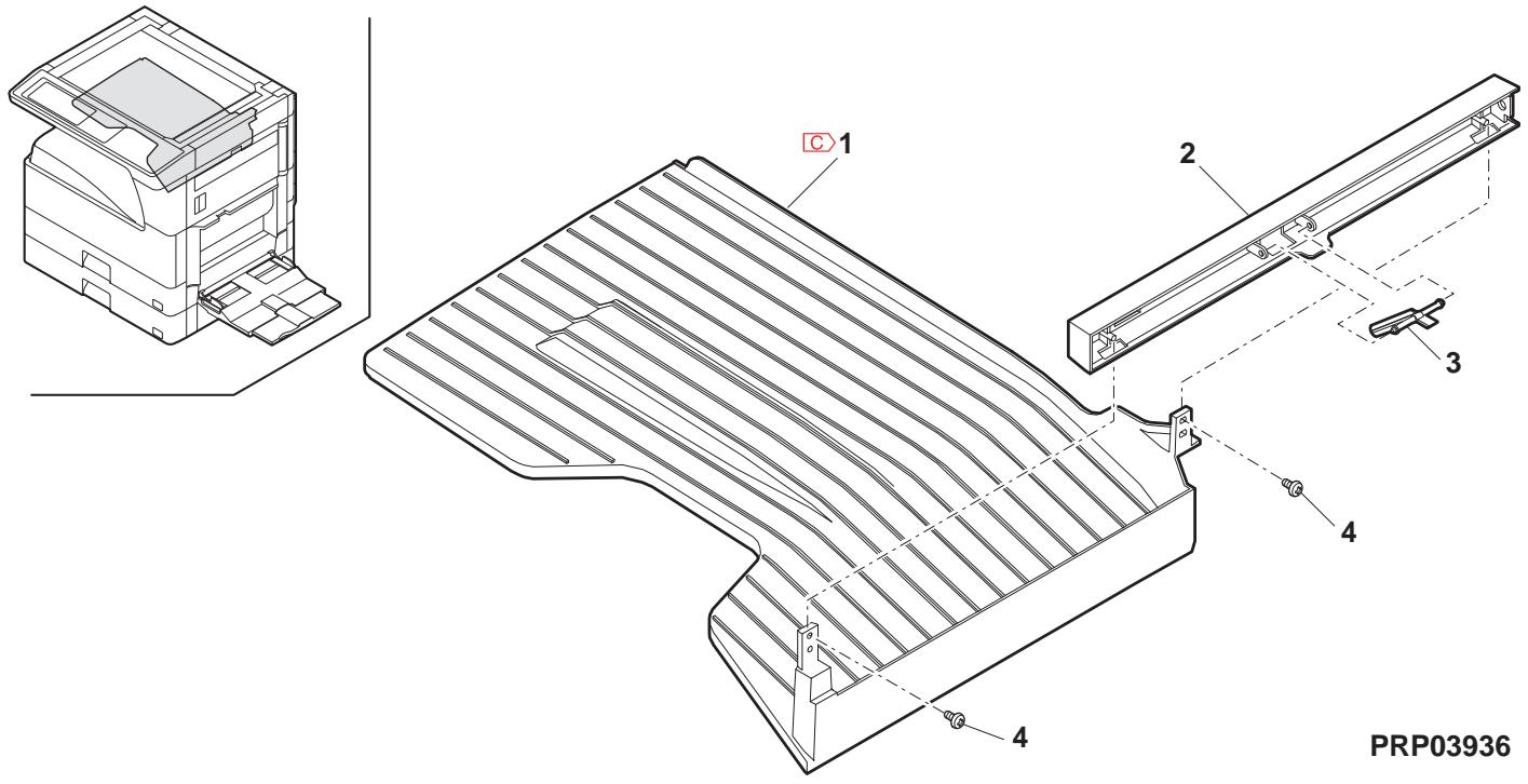
37 棍包及付属品 (Packing material & accessories)
| NO. | PARTS CODE | Inter-chang | PRICE RANK | NEW MARK | PART RANK | DESCRIPTION | TR No. | Effective time | |
| Ex. | Ja. | ||||||||
| 2 | TINSE2026QSZZ | AY | FQ | D | Operation manual [MX-M260/M310 English(North America)] 取拔說明書 | ||||
| TINSE2078QSZZ | BD | GN | D | Operation manual [English(Except North America,U.Kingdom)] 取拔說明書 | |||||
| TINSE2090QSZZ | - | BG | GX | D | Operation manual [Missing parts code] [MX-M Series English(U.Kingdom)] 取拔說明書 | 1st lot | |||
| TINSG2088QSZZ | - | BD | GN | D | Operation manual [Missing parts code] [German(Germany,Switzerland)] 取拔說明書 | 1st lot | |||
| TINSJ2031QSZZ | AY | FQ | D | Operation manual [Japanese] 取拔說明書 | |||||
| TINSE2027QSZZ | AK | DX | D | Operation manual(Copy/SPLC install guide) [English] 取拔說明書 | |||||
| TINSE2083QSZZ | AY | FQ | D | Operation manual(Copy/PCL install guide) [English MX-M260N/M310N] 取拔說明書 | |||||
| TINSG2089QSZZ | - | AR | EQ | D | Operation manual(Copy/SPLC install guide) [Missing parts code] [German(Germany,Switzerland)] 取拔說明書 | 1st lot | |||
| TINSJ2032QSZZ | AK | EB | D | Operation manual(Copy/SPLC install guide) [Japanese MX-M260FG/M310FG] 取拔說明書 | |||||
| TINSJ2033QSZZ | AN | EQ | D | Operation manual(Copy/SPLC install guide) [Japanese MX-M260FP/M310FP] 取拔說明書 | |||||
| TINSJ2034QSZZ | AW | FG | D | Operation manual(FAX) [Japanese] 取拔說明書 | |||||
| CDSKA0261QS31 | AH | DX | D | CD-ROM [MX-M260 North America] CD-ROM | |||||
| CDSKA0264QS31 | - | AL | EB | D | CD-ROM [Missing parts code] [MX-M Series(Except North America)] CD-ROM | 1st lot | |||
| CDSKA0265QS31 | AL | EB | D | CD-ROM(PDL DISK1) [MX-M260N/M310N] CD-ROM | |||||
| CDSKA0266QS31 | AL | EB | D | CD-ROM(PDL DISK2) [MX-M260N/M310N] CD-ROM | |||||
| CDSKA0267QS31 | AL | EB | D | CD-ROM [MX-M260FG/M310FG] CD-ROM | |||||
| CDSKA0268QS31 | AL | EB | D | CD-ROM [MX-M260FP/M310FP] CD-ROM | |||||
| TCADZ0049QSZZ | AH | DX | D | Installation report card (Germany,Switzerland,Europe,East Europe) 設置報告書 | |||||
| TCADS1693FCZZ | AA | DS | D | Installation report card (Japan) 設置報告書 | |||||
| TCADZ0098QSZZ | AF | DS | D | Warranty card SUK (U.kingdom) 保証かト'SUK | |||||
| CCADZ1518FC01 | AB | DJ | D | Maintenance card EX [MX-M260/M260N/M310N,AR-5726/5731] ナフクトEX | |||||
| CCADZ1561FC01 | AK | DX | D | Maintenance card J [MX-M260FG/M260FP/M310FG] ナフクトJ | |||||
| TGANE1001QCZB | AC | DJ | D | SCA warranty (Australia,New Zealand) SCA 保證書 | |||||
| QCNWG0013QSZZ | AF | DS | C | Line cable (Japan) ナフクトJ | |||||
| TKEI0001QSZZ | AE | DJ | D | Counter contract card (Japan) 加藤-契約書 | |||||
| 7 | SPAKA0484QSZZ | BE | GN | D | Bottom packing case (Japan) 底がス | ||||
| 8 | LX-BZ0015QSPZ | AF | DS | C | 2/3 fixing screw 2/3固定ごス | ||||
| 9 | TCADZ0010QSZZ | AC | DJ | D | Fixing screw caution card 固定ごス 注意ごス | ||||
| 10 | LHLDW1226FCZZ | AB | DJ | C | Turn fastener 報表変態 | ||||
| 11 | TCADZ1275FCZZ | AB | DJ | D | Cassette rotation tag はり回転け | ||||
| 12 | SSAKA3001CCZZ | AA | DD | D | Vinyl bag(140×360) (North America,Japan,Argentina) ボリ袋 | ||||
| SSAKA5003CCZZ | AA | DD | D | Vinyl bag(140×260) (Except North America,Japan) ボリ袋 | |||||
| 13 | SSAKA2343QCZZ | AA | DD | D | Vinyl bag(260×380) ボリ袋 | ||||
| 14 | SPAKA0134RSZZ | AL | EB | D | OC protect sheet OC 保護けト | ||||
| 15 | LBNDC0075FCZZ | AB | DJ | C | AC cord band (Except North America,Japan,India, Special country,Philippines,Malaysia,Singapore) AC ナフクト | ||||
| UBNDA0001FCZZ | AA | DD | C | AC cord band (India,Special country,Malaysia, Singapore,Argentina) AC ナフクト | |||||
| 17 | SPAKA3914FCZZ | AC | DJ | D | DV sleeve (Japan) DV ナフクト | ||||
| 19 | TLABZ0106RSZZ | AF | DS | D | LAG 4 label (Argentina) LAG4 ナフクト | ||||
37 棍包及付属品 (Packing material & accessories)
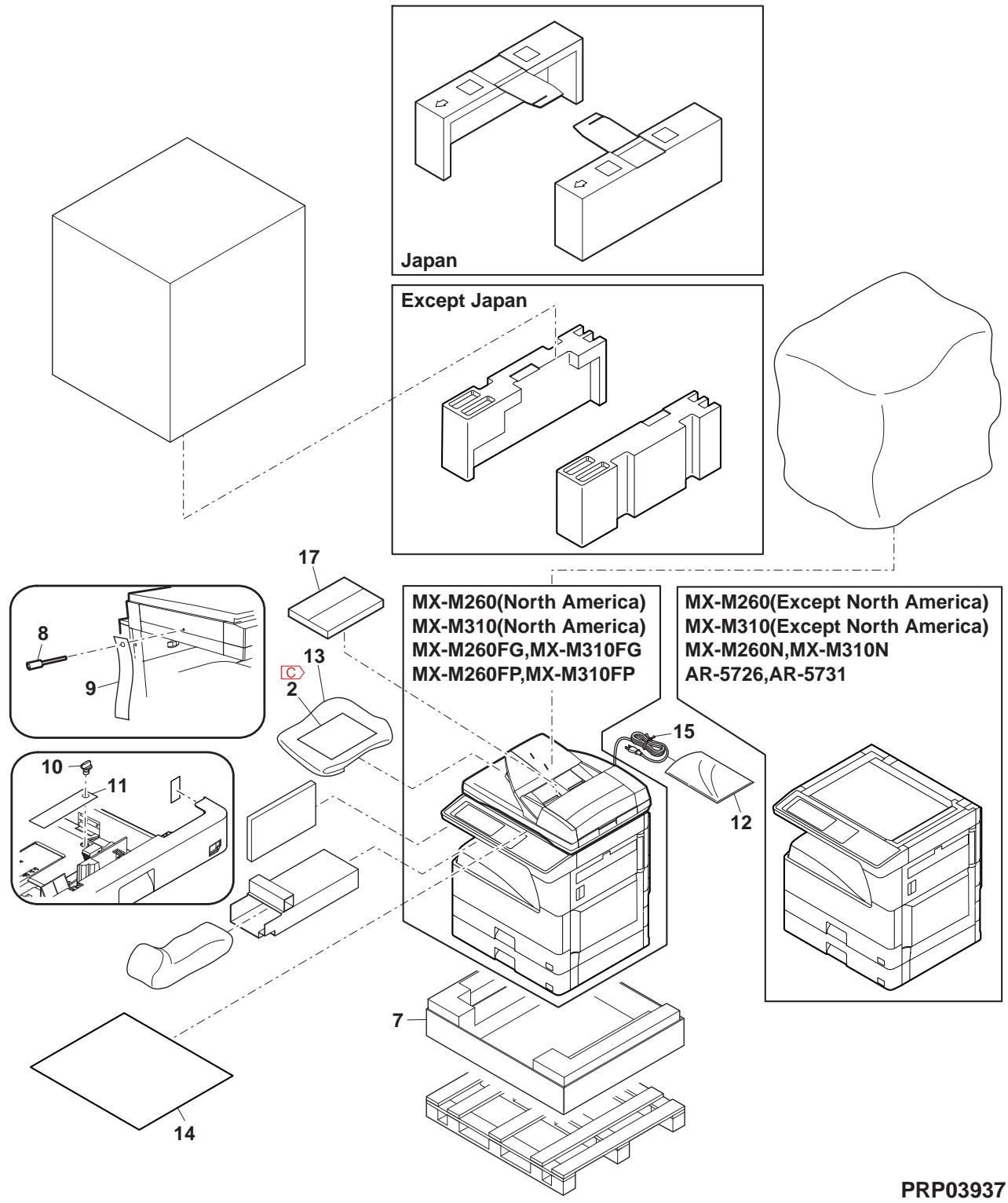
38 MX-VR10 棍包及付属品 (MX-VR10 Packing material & accessories)
| NO. | PARTS CODE | Inter-changese | PRICE RANK | NEWMARK | PARTRANK | DESCRIPTION | TR No. | Effective time | |
| Ex. | Ja. | ||||||||
| 1 | GCÖV-0 075QSZ1 | BB | GD | D | OC cover | OC 加* - | |||
| 2 | GCÖV-0 247FCZZ | AS | EQ | D | OC stocker | OC ストウェー | |||
| 3 | PCUSS0 032QSZZ | AW | FG | C | OC mat | OC マフ | |||
| 4 | MHNG-0 025QSTZ | BC | GD | C | OC hinge R | OC ハング * R | |||
| 5 | XWVS740-05000 | AA | DD | C | Washer | ウashi | |||
| 6 | XEBS740P12000 | AA | DD | C | Screw(4×12) | ビス | |||
| 7 | MHNG-0 026QSTZ | BC | GD | C | OC hinge L | OC ハング * L | |||
| 14 | SSAKH3012KCZZ | AD | DJ | D | Vinyl bag | ロリ袋 | |||
| (Unit) | |||||||||
| 901 | CCÖV-0 075RS53 | - | BK | HC | E | OC cover unit | OC 加* -�ルト | ||
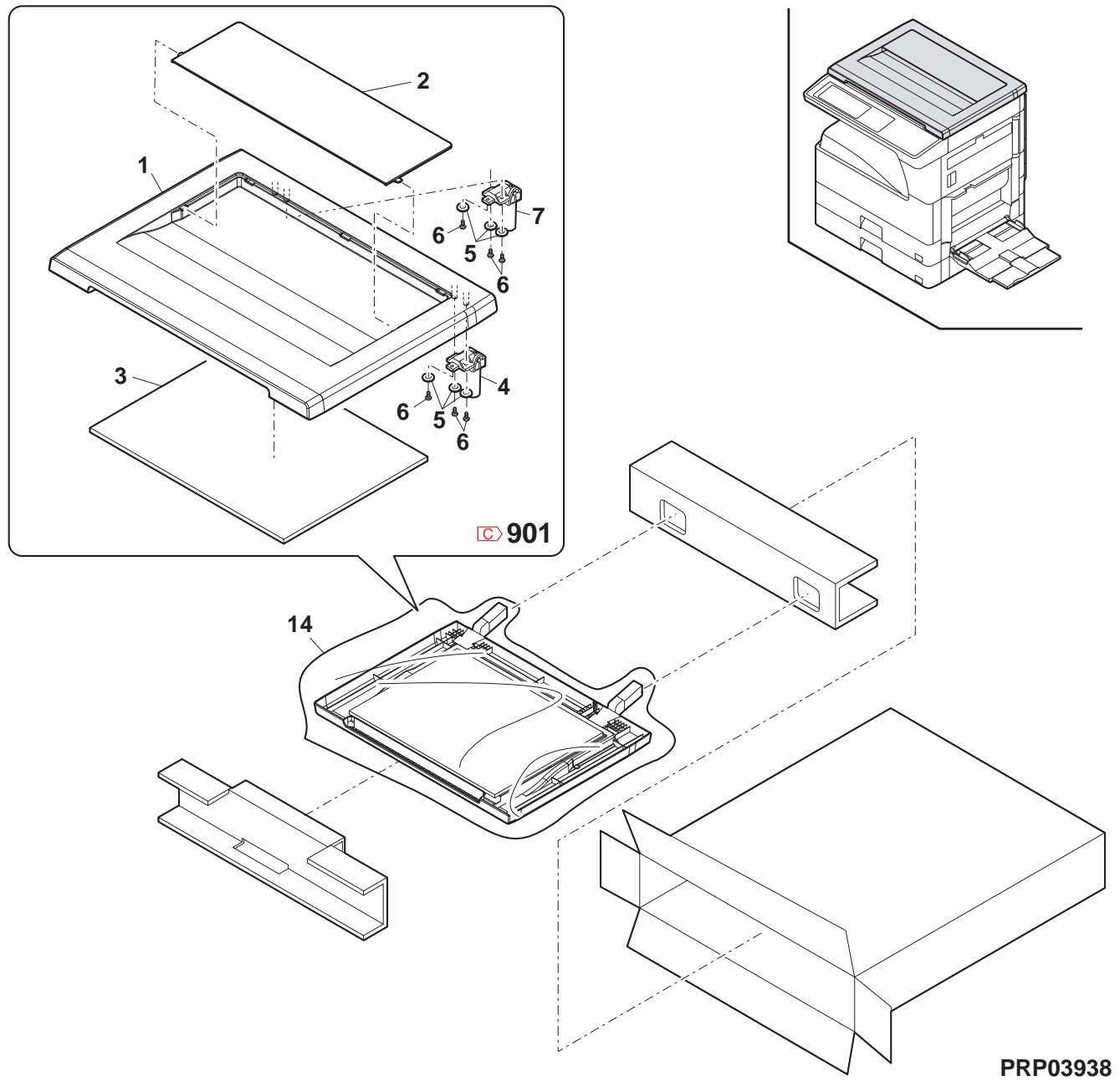
39 MX-RP10 棍包及付属品 (MX-RP10 Packing material & accessories)
| NO. | PARTS CODE | Inter-changese | PRICE RANK | NEWMARK | PARTRANK | DESCRIPTION | TR No. | Effective time | |
| Ex. | Ja. | ||||||||
| 1 | SPAKA0088QSZZ | AE | DS | D | Protect packing sheet | 保護�� | |||
| 2 | CFiX-0012RS54 | AU | EZ | E | SPF glass fixing plate unit | SPFがフロー | |||
| 3 | SSAKZ0004QSZZ | AA | DD | D | Vinyl bag(80×450) | 木袋 | |||
| 6 | SSAKH3012KCZZ | AD | DJ | D | Vinyl bag | 木袋 | |||
| 7 | SPAKA0488QSZZ | BK | HG | D | Add R | トR | |||
| 9 | SPAKA0487QSZZ | BF | GN | D | Add L | トL | |||
| 10 | LSOU-0041QST1 | AP | EQ | C | Middle tray | 中間トリ | |||
| 11 | SSAKA1341QCZZ | AA | DD | D | Vinyl bag(180×380) | 木袋 | |||
| 12 | SPAK-545ECCZZ | AA | DD | D | Vinyl bag | 静電木袋 | |||
| 14 | SPAKA0622QSZZ | AG | DX | D | OC mat fixing add | OC マト固定材 | |||
| 15 | CCLEZ0020QS01 | AK | EB | D | SPF glass cleaner | SPFがフロー | |||
| 16 | TLABS3760FCZZ | AC | DJ | D | CE label | CE フロー | |||
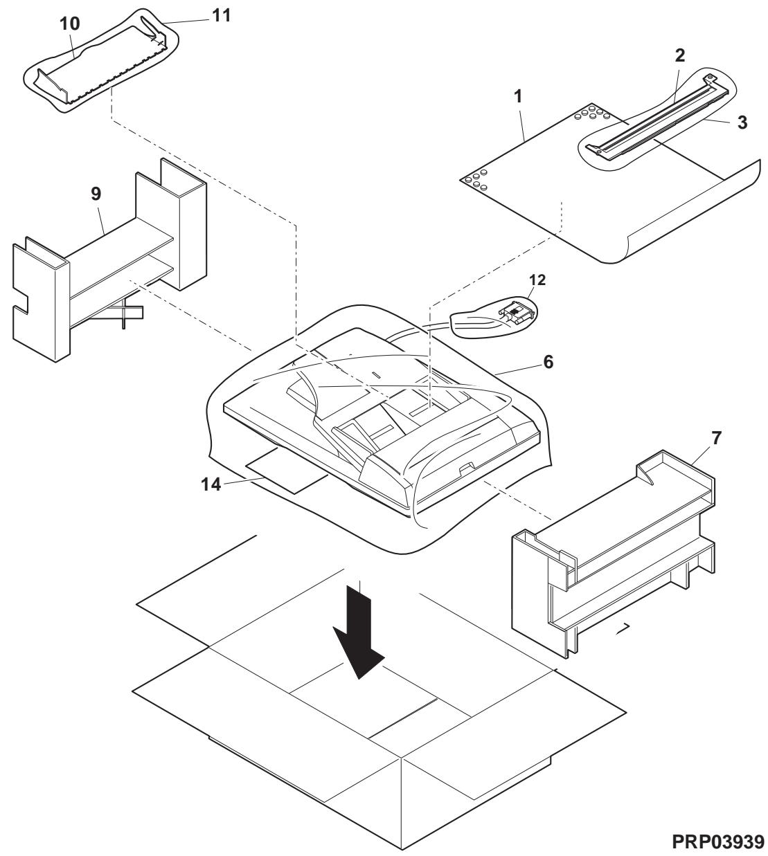
40 MX-TR11 棍包及付属品 (MX-TR11 Packing material & accessories)
| NO. | PARTS CODE | Inter-changese | PRICE RANK | NEWMARK | PARTRANK | DESCRIPTION | TR No. | Effective time | |
| Ex. | Ja. | ||||||||
| 1 | X E B S 7 4 0 P 1 0 0 0 0 | AA | DD | C | Screw(4×10) | 匕'λ | |||
| 2 | X H B S 7 4 0 P 1 0 0 0 0 | AA | DD | C | Screw(4×10) | 匕'λ | |||
| 3 | SS A K A 0 0 0 6 U C Z Z | AA | DD | D | Vinyl bag(50×60) | 木'袋 | |||
| 4 | L H L D Z 0 1 4 9 Q S Z Z | AH | DX | C | 2nd delivery holder | 第2排紙札の- | |||
| 7 | SS A K - 4 2 7 1 C C Z Z | AD | DJ | D | Vinyl bag(420×690) | 木'袋 | |||
| 9 | SS A K A 2 5 4 0 Q C Z Z | AB | DD | D | Vinyl bag(260×560) | 木'袋 | |||
| 10 | N PSHEZ 0 6 6 5 Q S Z Z | - | AC | DJ | C | Optical frame sheet | 光学レーパー- | 09/08 Mid | |
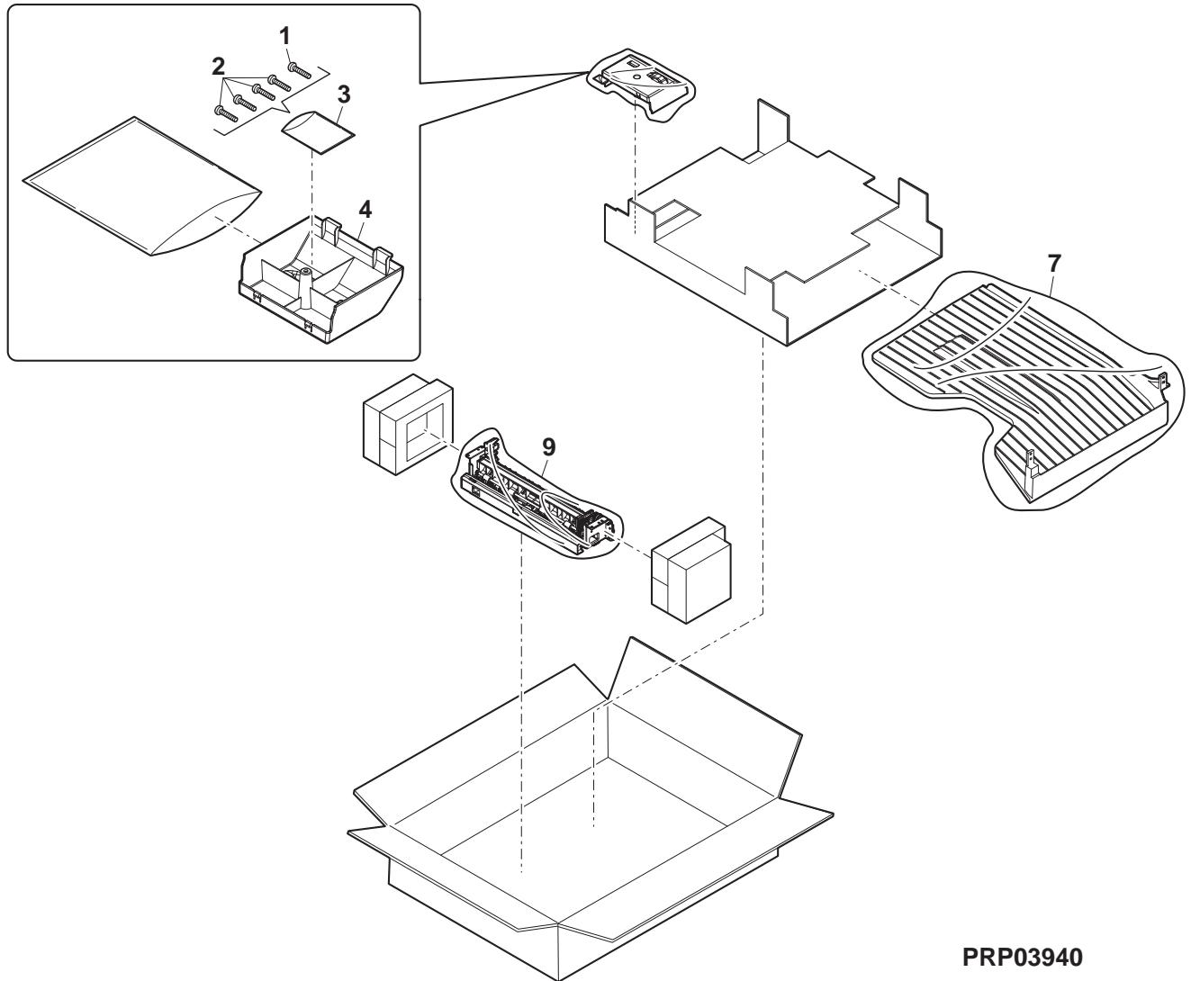


- SYSTÈME MULTIFONCTION NUMÉRIQUE
- MODÈLE AR
- SOMMAIRE
- NOTE POUR L'ENTRETIEN
- [1] APERÇU DU PRODUIT
- [2] SPÉCIFICATIONS
- [3] PIÈCES CONSOMMABLES
- [4] VUE EXTERNE ET STRUCTURE INTERNE
- [5] RÉGLAGES
- [6] SIMULATION
- [7] AUTODIAGNOSTIC ET CODES D'ANOMALIE
- [8] MAINTENANCE
- [9] MISE À JOUR DU FIRMWARE
- [10] SECTION ÉLECTRIQUE
- AVERTISSEMENT POUR L'ENTRETIEN
- PRÉCAUTIONS DE MAINTENANCE
- NOTE POUR LA RÉPARATION/LE REMPLACEMENT DU LSU
- GAMME DE MACHINES ET OPTIONS
- FONCTION DE BASE
- MOTEUR DE BASE
- CARTE CONTRÔLEUR
- SECTION SCANNER
- SECTION DE SORTIE PAPIER
- FONCTIONS DE COPIE
- FONCTION IMPRIMANTE
- CONDITIONS ENVIRONNEMENTALES
- TABLEAU DU SYSTÈME D'ALIMENTATION
- LISTE DES PIÈCES DE MAINTENANCE
- DÉFINITION DE LA FIN DE VIE DU DÉVELOPPEUR/TAMBOUR
- IDENTIFICATION DU NUMÉRO DE PRODUCTION
- VUE EXTERNE
- STRUCTURE INTERNE
- PANNEAU DE COMMANDE
- RSPF
- CAPTEUR
- INTERRUPTEUR
- ÉLECTROVANNE/EMBRAYAGE
- MOTEUR D'ENTRAÎNEMENT
- LISTE DES ÉLÉMENTS DE RÉGLAGE
- DÉTAILS DU RÉGLAGE
- SECTION DE TRAITEMENT
- RÉGLAGE DE L'ÉCART DU DOCTEUR DE DÉVELOPPEMENT
- RÉGLAGE DE LA POSITION DU PÔLE PRINCIPAL DU ROULEAU MG
- RÉGLAGE DE LA TENSION DE POLARISATION DE DÉVELOPPEMENT (SIM 8-1)
- RÉGLAGE DE LA TENSION DE POLARISATION DE GRILLE (SIM 8-2)
- SECTION MÉCANISME
- RÉGLAGE DE LA POSITION DE DÉBUT D'IMPRESSION
- RÉGLAGE DE LA POSITION DU BORD AVANT DE L'IMAGE RSPF
- RÉGLAGE DE LA MARGE ARRIÈRE
- AJUSTEMENT DU DÉCALAGE PAPIER
- AJUSTEMENT DE LA ZONE DE MARGE GAUCHE
- RÉGLAGE DE L'ÉQUILIBRE DE DISTORSION DANS LE SENS DE BALAYAGE PRINCIPAL (DIRECTION FR)
- RÉGLAGE DE LA DISTORSION DANS LE SENS DE BALAYAGE SECONDAIRE (SENS DE NUMÉRISATION) (RÉGLAGE DE LA POSITION DE LA POULIE D'ENROULEMENT)
- RÉGLAGE DE L'ÉQUILIBRE DE DISTORSION DANS LE SENS DE BALAYAGE PRINCIPAL (DIRECTION FR) (RÉGLAGE DE LA HAUTEUR DU RAIL)
- RÉGLAGE DU TAUX DE GRANDISSEMENT DANS LE SENS DE BALAYAGE PRINCIPAL (DIRECTION FR) (SIM 48-1)
- RÉGLAGE DU TAUX DE GRANDISSEMENT DANS LE SENS DE BALAYAGE SECONDAIRE (SENS DE BALAYAGE) (SIM 48-1-2, SIM 48-1-3)
- MODE OC EN COPIE
- MODE RSPF EN COPIE
- RÉGLAGE DU DÉCENTREMENT (MODE RSPF)
- RÉGLAGE DE LA POSITION DE DÉTECTION D'OUVERTURE/FERMETURE DE L'OC (RSPF)
- RÉGLAGE DU CAPTEUR D'ORIGINAL (SIM 41-2, 41-4)
- RÉGLAGE DE LA POSITION DE CORRECTION DU POINT BLANC RSPF (REQUIS DANS UN MODÈLE RSPF LORS DU REMPLACEMENT DE L'UNITÉ DE LENTILLE) (SIM63-7)
- RÉGLAGE AUTOMATIQUE DE LA POSITION DE NUMÉRISATION RSPF
- [FONCTION]
- [OPÉRATION]
- AJUSTEMENT DE LA DENSITÉ (EXPOSITION) DE L'IMAGE
- MODE COPIE (SIM46-2)
- GÉNÉRALITÉS
- APERÇU ET OBJECTIF
- SIMULATION DE TYPE CODE
- PROCÉDURES ET OPÉRATIONS
- COMMENT MODIFIER LA VALEUR DE RÉGLAGE DE SIMULATION DÉFINIE PAR LE PANNEAU TACTILE LORS DU PROCESSUS DE SAISIE DE LA VALEUR DE RÉGLAGE
- LISTE SIM CIBLE
- PROCÉDURE D'UTILISATION DU PANNEAU TACTILE
- DÉTAILS DE LA SIMULATION
- OPÉRATION/PROCÉDURE
- OPÉRATION / PROCÉDURE
- [SÉLECTION 2]
- (RÉGLAGE DE LA POSITION MAXIMALE)
- [7] AUTO-DIAGNOSTIC ET CODES D'ERREUR
- LISTE DE MAINTENANCE (POUR 26 CPM)
- (POUR 31 CPM)
- DÉTAILS DE LA MAINTENANCE
- PROCESS UNIT
- (NOTE POUR L'ENTRETIEN DES TAMBOURS OPC)
- PRÉVENTION DE LA FIXATION DE SALETÉS GRASSES
- [MESURES CORRECTIVES]
- [MÉTHODE DE VÉRIFICATION]
- PRÉVENTION DE L'EXPOSITION PRÉALABLE
- REMARQUE
- [CONTREMESURES]
- TAMBOUR
- SECTION TAMBOUR
- CHARGEUR PRINCIPAL
- RACLETTE DE NETTOYAGE
- CADRE DU TAMBOUR
- GRIFFE DE SÉPARATION
- SECTION DE DÉVELOPPEMENT
- UNITÉ DE FILTRE À TONER
- CAPTEUR DE TONER
- OPTICAL SECTION
- ALIMENTATION PAPIER DU BAC DE 500 FEUILLES INFÉRIEUR
- UNITÉ DE PORTE LATÉRALE
- UNITÉ LASER
- LSU
- UNITÉ D'ALIMENTATION
- PWB
- AUTRES ÉLÉMENTS CONNEXES
- PROCÉDURE DE MISE À JOUR DU FIRMWARE
- (ÉLÉMENTS NÉCESSAIRES POUR LA MISE À JOUR)
- (CARTE CIBLE)
- PRÉPAREZ LES FICHIERS SUIVANTS NÉCESSAIRES À LA MISE À JOUR DU PROGRAMME
- MÉTHODE DE MISE À JOUR DU FIRMWARE (POUR LE COPIEUR ET LE FIRMWARE FAX)
- AUTRES (DÉPANNAGE)
- SCHÉMA FONCTIONNEL
- SCHÉMA FONCTIONNEL DU SYSTÈME
- SCHÉMA DE CÂBLAGE RÉEL
- SOUDURE SANS PLOMB
- REMARQUE CONCERNANT L'UTILISATION DU FIL DE SOUDURE SANS PLOMB
- NOTE POUR LES TRAVAUX DE SOUDURE
- MODÈLE MX-TR
- TABLE DES MATIÈRES
- CLASSEMENT DES PIÈCES DE RECHANGE
- DÉFINITION
- EXTÉRIEURS
- フレーム部 (SECTION DU CHÂSSIS)
- 手差手(MULTI MANUAL PAPER FEED TRAY UNIT)
- 手差L給紙(MULTI MANUAL PAPER FEED UNIT)
- 第一排紙1-1 (1ST DELIVERY PAPER UNIT 1)
- ND 搬送部 (2ND PAPER TRANSFER SECTION)
- E SECTION DE TRANSPORT DU PAPIER (2ND PAPER TRANSFER SECTION)
- EXTÉRIEURS MX-RP10 2 (MX-RP10 EXTERIORS 2)
- SECTION D'ALIMENTATION PAPIER MX-RP10 (MX-RP10 PAPER FEEDING SECTION)
- MX-RP10 搬送部 2 (MX-RP10 TRANSPORT SECTION 2)
- 棍包及付属品 (PACKING MATERIAL & ACCESSORIES)
Marque : SHARP
Modèle : AR 5726
Catégorie : Imprimante