
SI 600 ACS 24V - Système de climatisation DOMETIC - Notice d'utilisation et mode d'emploi gratuit
Retrouvez gratuitement la notice de l'appareil SI 600 ACS 24V DOMETIC au format PDF.

| Type de produit | Onduleur avec commutateur de transfert |
| Marque | DOMETIC |
| Modèle | SI 600 ACS 24V |
| Puissance continue | 600 W |
| Puissance de crête | 800 W |
| Tension d'entrée nominale | 24 V CC |
| Tension de sortie | 230 V CA ± 3 % |
| Fréquence de sortie | 50 Hz ± 0,05 % |
| Onde de sortie | Onde sinusoïdale pure (THD < 3 %) |
| Rendement maximal | 90 % |
| Courant à vide | 0,43 A |
| Commutateur de transfert intégré | 7 A, temps de transfert 4-8 ms |
| Protection GFCI | Oui, via prise GFCI |
| Protections | Surtension, sous-tension, surcharge, court-circuit, inversion de polarité, surchauffe |
| Indicateurs LED | Niveau d'entrée, niveau de charge, état de fonctionnement (3 couleurs) |
| Commande à distance | Optionnelle (RJ-11) avec fonction ROF ou verrouillage allumage |
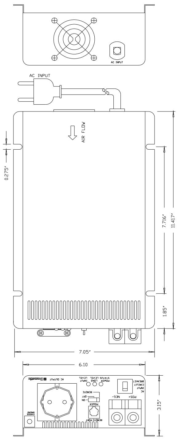
| Dimensions (L x l x H) | 29,0 x 17,9 x 8,0 cm (11,42 x 7,05 x 3,15 pouces) |
| Poids | 3,3 kg |
| Température de fonctionnement | -25 °C à 50 °C |
| Refroidissement | Ventilateur commandé par la charge |
| Entretien | Nettoyer l'extérieur avec un chiffon humide ; vérifier et serrer les bornes CC |
| Homologations | UL 458, FCC classe B, CE |
FOIRE AUX QUESTIONS - SI 600 ACS 24V DOMETIC
Questions des utilisateurs sur SI 600 ACS 24V DOMETIC
0 question sur cet appareil. Repondez a celles que vous connaissez ou posez la votre.
Poser une nouvelle question sur cet appareil
Téléchargez la notice de votre Système de climatisation au format PDF gratuitement ! Retrouvez votre notice SI 600 ACS 24V - DOMETIC et reprennez votre appareil électronique en main. Sur cette page sont publiés tous les documents nécessaires à l'utilisation de votre appareil SI 600 ACS 24V de la marque DOMETIC.
MODE D'EMPLOI SI 600 ACS 24V DOMETIC
SI 600 acs - 12V/24V
Pure Sine Wave Inverter
230Vac from 12Vdc / 24Vdc source
Integrated automatic 230Vac transfer switch - aCS
User's Manual / Benutzerhandbuch / Manuel de l'utilisateur
Användarhandbok / Manuale d'uso / Manual del usuario
Welcome to the Dometic world
Dometic Pure Sine wave Inverters – A sign of comfort
The SI 600acs Inverter is designed as a stand -alone power inverter with an AC transfer switch feature with a bypass for an AC utility connection when available. This Inverter is extremely suitable for RV, Commercial Vehicle, Marine and Emergency appliances.
When utility AC power is cut off, the transfer relay is de-energized and the load is automatically transferred to the SI 600acs output and driven by your 12 or 24 Vdc source. Once the AC utility is restored, the relay is energized and the load is automatically reconnected to the AC utility.
You have made a wonderful choice to use Inverters from Domatic. Feel free to contact our dealers for more information or other recommendations within mobile power supply.
Best regards,
Domatic
Contents
1 Important Safety Instructions 1
1.1 General Safety Precautions 1
1.2 Precautions When Working with Batteries 1
2 Basic Descriptions 2
2.1 Mechanical drawings 2
2.2 The Front panel interface 3
2.3 The rear panel interface 4
2.4 The Remote Control panel 5
3 Functional Characteristics 6
3.1 General Information 6
3.2 Features 7
3.3 Electrical Performance 8
4 Installation 9
4.1 Where to install 9
4.2 AC Safety Grounding 10
4.3 Ground Fault Circuit Interrupters (GFCI): 10
4.4 Making DC Wiring Connections 11
5 Operation 13
5.1 Controls and indicators: 13
5.2 System Status LEDs. 14
6 Information 15
6.1 Troubleshooting 15
6.2 Maintenance 16
6.3 Warranty 16
Copyright: This manual is the copyright of DOMETIC and may not be reproduced or copied without the express permission of the owner.
1 Important Safety Instructions
WARNING!
Before you install and use your Domatic SI 600acs Inverter, be sure to read these safety instructions.

1.1 General Safety Precautions
1-1-1. Do not expose the SI 600acs inverter to rain, snow, spray, bilge or dust. To reduce risk of hazard, do not cover or obstruct the ventilation openings. Do not install the SI 600acs Inverter in a zero-clearance compartment. Overheating may result.
1-1-2. To avoid the risk of fire or electric shock, make sure that existing wiring is in good electrical condition and that wire size is not under sized. Do not operate the SI 600acs inverter with damaged or substandard wiring.
1-1-3. This equipment contains components which can produce arcs or sparks. To prevent fire or explosion do not install in compartments containing batteries or flammable materials or in locations which require ignition protected equipment. This includes any space containing gasoline-powered machinery, fuel tanks, or joints, fittings, or other connections between components of the fuel system.
1.2 Precautions When Working with Batteries
1-2-1. If battery acid contacts skin or clothing, wash immediately with soap and water. If acid enters eye, immediately flood eye with running cold water for at least 20 minutes and seek medical attention at once.
1-2-2. Never smoke or allow a spark or flame in vicinity of battery or engine.
1-2-3. Do not drop a metal tool on the battery. The resulting spark or short-circuit on the battery or other electrical part may cause an explosion.
1-2-4. Remove personal metal items such as rings, bracelets, necklaces, and watches when working with a lead-acid battery.
A lead-acid battery produces a short-circuit current high enough to weld a ring or other metal, causing a severe burn.
2 Basic Descriptions
2.1 Mechanical drawings
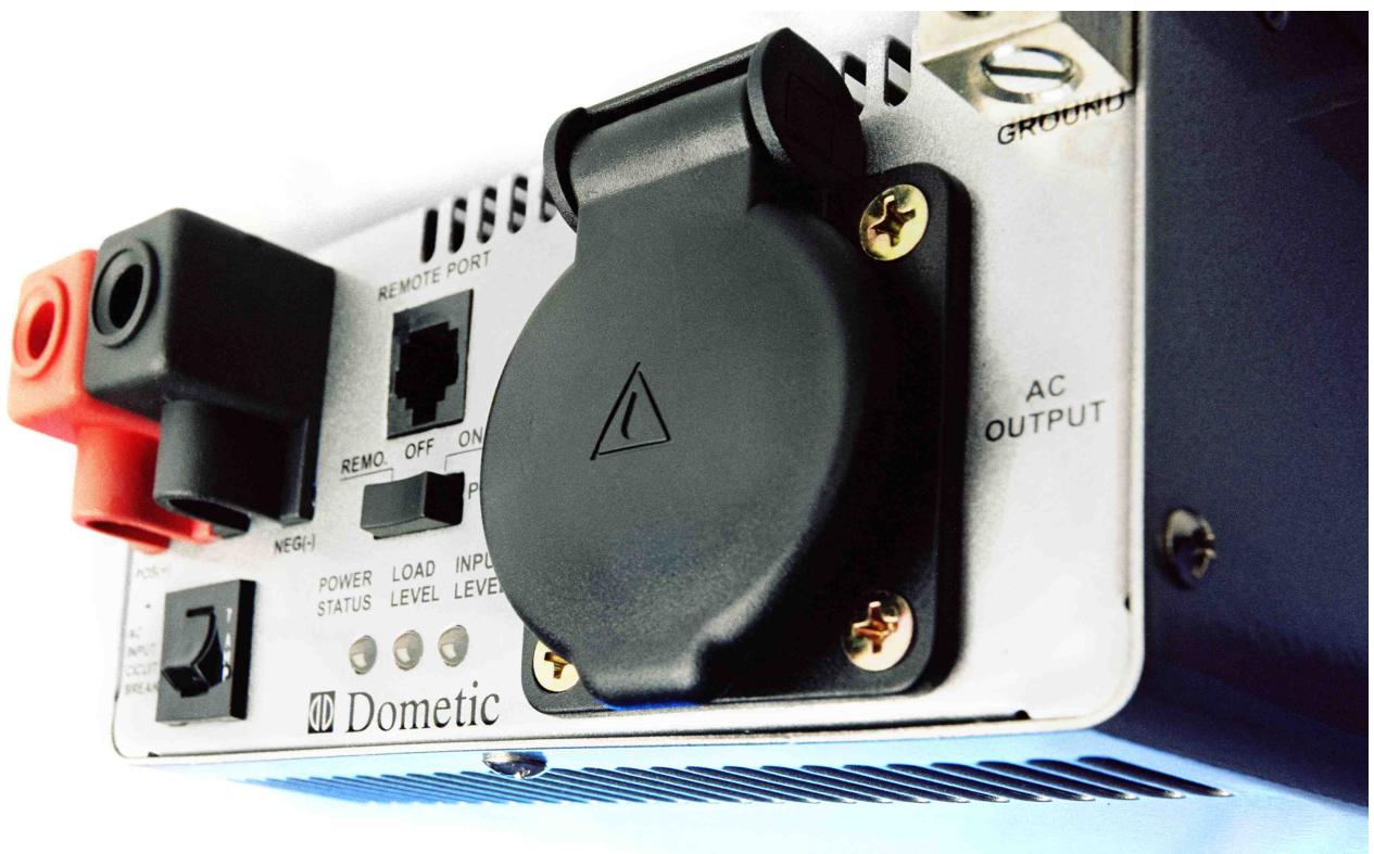
2.2 The Front panel interface
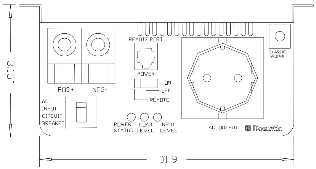
2-2-1. Power ON / OFF / REMOTE switch: If you use the optional remote control unit, put the "on/off" switch to "remote".
2-2-2. 230Vac input Circuit Breaker:The 7Amp circuit breaker protects the model from overload. When an overload condition exists, the circuit breaker stops output AC grid power. To reset, push the circuit breaker switch and then the model will be back to a normal operation. The source fault should be corrected prior reset.
2-2-3. Remote port: Connect RJ-11 wiring with remote control unit.
2-2-4. Battery terminals: Connect 12V/24V batteries or other 12V/24V power sources.
2-2-5. Chassis ground: Connect the inverter chassis ground terminal to earth.
2.3 The rear panel interface
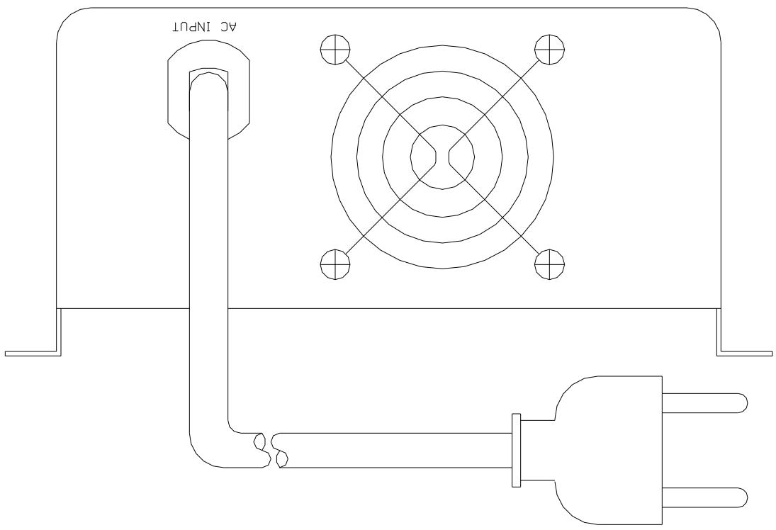
2-3-1. Ventilation:
Do not obstruct, allow at least 2-3 inches/ 50-75mm of clearance for airflow.
2-3-2. 230V AC input: (source)
If available and desired, plug into 230Vac source directly.
2.4 The Remote Control panel
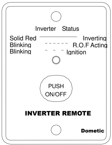
The Remote control is a basic ON/ OFF remote control. The control has features which disable and override the ON/OFF function such as:
Ignition Lockout function
This will automatically turn the Inverter OFF when the auxiliary input wiring receives a continuous 12V/24V signal.
R.O.F (Remote override function)
This will automatically turn the Inverter ON when the auxiliary input wiring receives a continuous 12V/24V signal. (The auxiliary input wire must be placed with a 12/24 Volt fuse (0.5A))
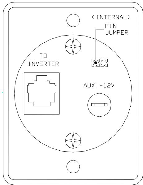
The internal pin jumper that is placed inside the remote control stipulates a choice, either the Ignition lockout or R.O.F function:
Pin jumper "Short" - Ignition lockout function.
Pin jumper "Open" - R.O.F.
LED Signals
- The LED glows steadily red when the Inverter is on.
- The LED blinks fast when the R.O.F function is enabled.
- The LED blinks slowly when the Ignition Lockout function is enabled.
Connect RJ-11 wire with the remote port in front of panel of the Inverter.
3 Functional Characteristics
3.1 General Information
The SI 600acs Inverter is designed as a stand -alone power inverter with an AC transfer switch feature which is suitable for RV, marine and emergency appliances.
When utility AC power is cut off, the transfer relay is de-energized and the load is automatically transferred to the SI 600acs output. Once the AC utility is restored, the relay is energized and the load is automatically reconnected to the AC utility.
The SI 600acs is also GFCI compliant. This provides with the GFCI safety receptacle easier use of appliances.
Please read all instructions and cautionary marking on this manual before using SI 600acs series.
3.2 Features
Product:
600W continuous output with 800W power surge for electronic appliances.
Pure sine wave output (THD < 3%) to operate higher-end electronic equipment.
Built in 7A rating AC transfer switch with plug-in socket that is easy to maintain.
- Speed up transfer time and synchronized operation with the AC source at all times which allows the transfer to be interruption-free for sensitive equipment.
Built in advance microprocessor for user friendly interface and operation.
■ Optional smart remote control.
3 tri-color LED indicators display all operation status.
UL 458 approval and FCC class B.
Protection:
Battery over- and under voltage protections.
Over temperature protection.
Over load protection.
Short Circuit protection.
Ground fault protection by GFCI receptacle.
Reverse polarity protection.
■ ROF (remote override function) or Ignition Lockout function option.
AC circuit breaker (7Amp).
3.3 Electrical Performance
| Specification | Model No. | |
| Item | SI600acs 24V | SI600acs 12V |
| Continuous Output Power | 600W | |
| Maximum Output Power (3Min.) | 680W | |
| Surge Rating | 800W | |
| Input Voltage | 24V | 12V |
| Output Voltage / Frequency | 230V ± 3% | |
| 50Hz +/- 0.05% | ||
| Efficiency (full load) | 90.0% | |
| No Load Current Draw | 0.43A | 0.87A |
| Output Waveform | Pure Sine Wave (THD <3%) | |
| Power Factor Allowed | cos.-90° ~ cos.+90° | |
| Output Voltage Regulation | 230V | |
| Input Voltage Regulation | 21.0-30VDC | 10.5-15VDC |
| Input Level Indicator | Red / Orange / Green LED | |
| Load Level Indicator | ||
| Power Status | Red / Green LED | |
| Protection | Overload, Short Circuit, Reverse Polarity (Fuse), Over/Under Input Voltage, Over Temperature. AC Input Circuit Breaker, GFCI. | |
| ACS Circuit Breaker | 7Amp | 7Amp |
| ACS Transfer switch | 10Amp | |
| ACS Transfer Time | 4~8 msec. | |
| Safety | UL458/CE | |
| EMC | FCC Class B | |
| Optional Remote Control | YES | |
| Synchronous AC transfer | ||
| Operating Temperature Range | -25°C to 50°C | |
| Storage Temperature Range | -30°C to 70°C | |
| Cooling | Loading controlled cooling fan | |
| Dimensions | 11.42 (L) x 7.05 (W) x 3.15 (H) Inch | |
| Weight | 3.3 kgs. / 6.6 Lbs. | |
4 Installation
4.1 Where to install
The power inverter should be installed in a location that meets the following requirements:
4-1-1. Dry – Do not allow water to drip or splash on the inverter.
4-1-2. Cool - Ambient air temperature.
4-1-3. Safety - Do not install batteries in a compartment or other areas where flammable fumes existence such as fuel storage areas or engine compartments.
4-1-4. Ventilated – Allow at least 2 to 3 inches/ 50-75mm of clearance around the Inverter for air flow. Ensure the ventilation openings on the rear and bottom of the unit are not obstructed.
4-1-5. Dust-free – Do not install the SI 600acs Inverter in a dusty environment where there is dust, wood particles or other filings/shavings present. These dusts can be pulled into the unit when the cooling fan is operation.
4-1-6. Near the battery – avoid excessive cable lengths. Do not install the SI 600acs Inverter in the same compartment as batteries. Use the recommended wire lengths and sizes. Also do not mount the SI 600acs Inverter where it will be exposed to the gases produced by the battery. These gases are very corrosive and prolonged exposure also will damage the SI 600acs Inverter.
WARNING!
Do not connect output terminal of the SI 600acs Inverter to an incoming 230VAC source. This could permanently damage the inverter and will void warranty.

4.2 AC Safety Grounding
During the AC wiring installation, AC input and output grounding should be present in the connection with the inverter. The AC input grounding must connect to the incoming grounding of your AC utility sources and the AC output grounding should connect to the grounding point for your loads (for example, a distribution panel ground bus).
Neutral Grounding (GFCI'S):
The neutral conductor of the AC output circuit of the SI 600acs Inverter is automatically connected to the safety ground during inverter operation. This conforms to National Electrical Code requirements that derived AC sources separately (such as inverter and generators) to have their neutral conductors tied to ground in the same way that the neutral conductor from the utility is tied to ground at the AC breaker panel.
For models configured with a transfer relay, while AC utility power is in use and the SI 600acs Inverter is in bypass mode, this connection (neutral of the SI 600acs Inverter's AC output to input safety ground) is not presented so that the utility neutral is only connected to ground at your breaker panel, as required.
4.3 Ground Fault Circuit Interrupters (GFCI):
Recreational Vehicles Installations (for North American approvals) will require GFCI protection. In addition, electrical codes require GFCI protection of certain receptacles in residential installations.
While the pure sine wave output of the SI 600acs Inverter is equivalent to the waveform provided by utilities, compliance with UL standards requires us to test and recommend specific GFCI.
The following GFCI-protected 20A receptacles, UL listed, Pass & Seymour, type no. 2091-W & 2094-W, have been tested and found that it functioned properly when connected to the output of the SI 600acs Inverter.
4.4 Making DC Wiring Connections
The following procedure is for connections between the battery and the DC input terminals on the SI 600acs Inverter. The cables should be high quality copper wiring and keep cable length as short as possible, the maximum length is 6 feet /2m which will handle the current required from the electrical codes or regulations.
If cables are not correctly dimensioned, the inverter performance will decrease. DC voltage will drop, poor surge capability, low input voltage warnings and shutdowns will be caused.
The longer the cables - the more the voltage will drop.
Battery cable fusing --- A fuse is required by the National Electrical Code (NEC) to protect the battery and cables, A UL listed DC rated slow blow fuse must be installed in line with the positive battery cable, within 18 inches/ 0.5m of the battery.
DOMETIC recommends the following cables for an optimum inverter performance.
| Model No | Wire | Inline Fuse |
| SI 600 ACS 12V | 25mm², AWG# 4 | 100A |
| SI 600 ACS 24V | 16mm², AWG# 6 | 50A |
Domatic SI 600acs
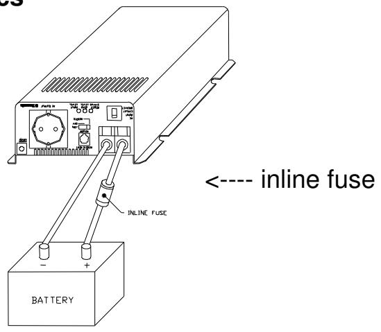
WARNING!
The installation of an inline fuse must be on positive cable. Failure to place a fuse on "+" cables running between the Inverter and battery may cause damage to the inverter and will void warranty.

5 Operation
To operate the SI 600acs Inverter, turn it on by using the ON/OFF/REMOTE switch. The inverter is now ready to deliver AC power to your loads. If you are loading several appliances, turn them on separately after the inverter is switched on; this process is to avoid delivering all the starting currents at once to all the loads.
5.1 Controls and indicators:
The ON/OFF switch turns on/off the control circuit of the power inverter. The inverter will function within voltage ranges as follows:
10.5 to 15.0 VDC for 12V models 21.0 to 30.0 VDC for 24V models
The SI 600acs Inverter indicates DC voltage status as follows:
| Model | DC Input over voltage shut-down | DC Input under voltage alarm | DC Input under voltage shut-down |
| SI 600acs 12V | 15.3V | 11.0V | 10.5V |
| SI 600acs 24V | 30.6V | 22.0V | 21.0V |
5.2 System Status LEDs.
There are 3 LED indicators located on the front panel of the inverter. Input Level, Load Level, and Power status.
- Input Level: Displays Input Voltage
| LED Status | DC 12V | DC 24V |
| Red Blink (slow) | 10.5~10.9 | 21.0~21.8 |
| Red | 10.9~11.3 | 21.8~22.6 |
| Orange | 11.3~12.0 | 22.6~24.0 |
| Green | 12.0~14.0 | 24.0~28.0 |
| Orange Blink | 14.0~14.7 | 28.0~29.4 |
| Red Blink | 14.7 | >29.4 |
- Load Level: Displays AC Load Watts
| LED Status | Load Condition |
| Dark | 0~30W |
| Green | 30W~200W |
| Orange | 200W~450W |
| Red | 450W~580W |
| Red Blink | Over 580W |
- Power status: Displays power good / fault status
| LED Status | Power Status |
| Green | AC power supplied from an external AC source |
| Orange | Supply AC power from an inverter |
| Red Blinking Fast | OVP: over voltage |
| Red Blinking Slowly | UVP: under voltage |
| Red Blinking Intermittently | OTP: over temperature |
| Red | OLP: over load |
6 Information
6.1 Troubleshooting
WARNING!
Do not open or disassemble the SI 600acs Inverter. Attempting to service the unit may result in a risk, electrical shock or fire.

| Problems and Symptoms | Possible Cause | Solutions |
| No output voltage, the LED glows RED light. | ||
| a. Power status light is blinking fast. | Over input voltage. | Check input voltage. Reduce input voltage. |
| b. Power status light is blinking slowly. | Low input voltage. | Recharge battery. Check connections and cables. |
| c. Power status light is blinking intermittently. | Thermal shutdown | Improve ventilation. Make sure ventilation openings in inverter are not obstructed. Try to reduce ambient temperature. |
| d. Power status light glows steadily. | Short circuit, wiring error, or over loading | Check AC wiring for short circuit or reduce load. |
6.2 Maintenance
To keep your inverter operating properly, there is very little maintenance required. You should clean the exterior periodically with a damp cloth to prevent accumulation of dust and dirt at the same time, tighten the screws on the DC input terminals.
6.3 Warranty
We warrant this product against defects in materials and workmanship for a period of 12 months from the date of purchase and will repair or replace any defective Dometic Inverter when directly returned, postage paid, to us.
This warranty will be considered void if the unit has suffered any obvious physical damage or alteration either internally or externally. The warranty does not cover damage arising from improper use such as plugging the unit into an unsuitable power sources or attempts to operate products with excessive power consumption requirements, or use in unsuitable environments.
This is the only warranty that the company makes. No other warranties express or imply including warranties of merchantability and fitness for a particular purpose.
Repair and replacement are your sole remedies and the company shall not be liable for damages, whether direct, incidental, special or consequential, even though caused by negligence or other fault.
Further Information about Dometic products
www.dometic.com