
SILUROMX - Carte graphique ABIT - Notice d'utilisation et mode d'emploi gratuit
Retrouvez gratuitement la notice de l'appareil SILUROMX ABIT au format PDF.


| Type de produit | Carte graphique |
| Marque | ABIT |
| Modèle | SILUROMX (série MX200/MX400/T200/T400) |
| Chipset | NVIDIA GeForce2 MX (MX200 ou MX400 selon modèle) |
| Mémoire vidéo | 32 Mo SDRAM (MX200/T200) ou 64 Mo SDRAM (MX400/T400) |
| Interface | AGP 2X/4X |
| Résolution maximale | 2048 x 1536 à 75 Hz |
| RAMDAC | 350 MHz intégré |
| Taux de remplissage | Jusqu'à 800 millions de texels/s (MX400) |
| Sorties vidéo | VGA, S-Video, Composite (selon modèle) |
| Support TV-Out | Oui (modèles T200/T400) |
| Support HDTV | Oui (720p via HDVP) |
| API supportées | DirectX 7.0, OpenGL |
| Alimentation | Via slot AGP (consommation typique ~20 W) |
| Dimensions (estimées) | 170 x 100 x 20 mm |
| Poids (estimé) | Environ 100 g |
| Systèmes d'exploitation | Windows 98, Windows 2000 |
| Fonctions principales | Accélération 2D/3D, lecture DVD, transform & lighting (T&L), Digital Vibrance Control (DVC), TwinView |
| Entretien | Nettoyer avec un chiffon doux et sec; éviter l'humidité |
| Sécurité | Manipuler avec précautions anti-statiques; débrancher l'alimentation avant installation |
| Pièces détachées et réparabilité | Non applicable; carte non réparable par l'utilisateur |
FOIRE AUX QUESTIONS - SILUROMX ABIT
Questions des utilisateurs sur SILUROMX ABIT
0 question sur cet appareil. Repondez a celles que vous connaissez ou posez la votre.
Poser une nouvelle question sur cet appareil
Téléchargez la notice de votre Carte graphique au format PDF gratuitement ! Retrouvez votre notice SILUROMX - ABIT et reprennez votre appareil électronique en main. Sur cette page sont publiés tous les documents nécessaires à l'utilisation de votre appareil SILUROMX de la marque ABIT.
MODE D'EMPLOI SILUROMX ABIT
Copyright and Warranty Notice
The information in this document is subject to change without notice and does not represent a commitment on part of the vendor, who assumes no liability or responsibility for any errors that may appear in this manual.
No warranty or representation, either expressed or implied, is made with respect to the quality, accuracy or fitness for any particular part of this document. In no event shall the manufacturer be liable for direct, indirect, special, incidental or consequential damages arising from any defect or error in this manual or product.
Product names appearing in this manual are for identification purpose only and trademarks and product names or brand names appearing in this document are property of their respective owners.
This document contains materials protected under International Copyright Laws. All rights reserved. No part of this manual may be reproduced, transmitted or transcribed without the expressed written permission of the manufacturer and authors of this manual.
If you do not properly set the Graphics Accelerator settings causing the motherboard to malfunction or fail, we cannot guarantee any responsibility.
| As of December 31, | ||
| 2017 | 2016 | |
| (In thousands) | ||
| Amounts Payable and Commitments: | ||
| Amounts payable to NagraStar | 1,458,938 | 1,458,938 |
SILURO™ MX200/MX400/T200/T400 Graphics Accelerator
Index
CHAPTER 1. INTRODUCTION 1-1
1-1. FEATURES 1-1
1-2. SPECIFICATIONS OF MX200/T200 1-2
1-3. SPECIFICATIONS OF MX400/T400 1-3
1-4. FEATURES AND BENEFITS 1-4
1-5. LAYOUT DIAGRAM 1-5
CHAPTER 2. HARDWARE SETUP 2-1
2-1. CARD INSTALLATION 2-1
2-2. VGA OUTPUT CONNECTION 2-2
2-3. TV OUTPUT CONNECTION (FOR T200/T400 ONLY) 2-2
2-4. VGA AND TV OUTPUT CONNECTION (FOR T200/T400 ONLY). 2-3
CHAPTER 3. SOFTWARE SETUP 3-1
3-1. INSTALL DISPLAY DRIVER FOR WINDOWS 98 3-1
3-2. INSTALL DISPLAY DRIVER FOR WINDOWS 2000 3-5
3-3. INSTALL WINDVDTM 2000 3-8
3-4. INSTALL DIRECTX 3-10
CHAPTER 4. UTILITY SETUP. 4-1
4-1. SETTING DISPLAY PROPERTIES IN WINDOWS 98 SE 4-1
4-2. SETTING DISPLAY PROPERTIES IN WINDOWS 2000 4-9
4-3. THE GRAPHIC MAX 4-17
4-4. THE 3DEEP COLOR 4-19
4-5. DISPLAY TRAY ICON 4-23
4-6. BIOS FLASHING UTILITY 4-24
APPENDIX A. DISPLAY MODES TABLE
APPENDIX B. PRODUCT FAQ
APPENDIX C. HOW TO GET TECHNICAL SUPPORT
Chapter 1. Introduction
1-1. Features
The SILURO GF2 MX series Graphics Accelerator provides you with powerful 3D acceleration and the most advanced Direct3D/OpenGL acceleration solution for games, professional 2D/3D CAD/CAM applications and 3D drawing applications.
The technology of SILURO GF2 MX series utilizes Digital Vibrance Control (DVC), which delivers crisper and brighter images for all 2D, 3D and video solutions. The SILURO family also incorporates the first shading GPU with the new Nvidia Shading Rasterizer (NSR) and a High Definition Video Processor (HDVP). Incorporating a radical new per-pixel shading processor, the GF2 MX series raises image quality to never-before-seen-heights for interactive content. Each of the four new rasterization pipelines now process two textures per pixel in life-like 32-bit color.
The SILURO's Second Generation transformation and lighting architecture now delivers more than 20 million triangles/sec, allowing even more realistic images. Integrated HDVP supports all ATSC resolutions, including 720p, at their specified frame rates. Combined with high performance MPEG-2 software decoder and a Digital TV receiver, The SILURO GF2 MX series provides a high quality HDTV playback solution. The SILURO GF2 MX series also enables groundbreaking new applications like HD time-shifting and digital VCR capabilities.
The SILURO GF2 MX series Graphics Accelerator is the most complete implementation of DX7 hardware and meets all the requirements of mainstream PC graphics, including Microsoft's PC00, PC99 and PC99a initiatives.
Combined with other innovations such as 3Deep and bundled with WinDVD, the SILURO GF2 MX series Graphics Accelerator caters for all your graphics needs. Delivering the industry's fastest Direct 3D and OpenGL acceleration, as well as integrated VGA/2D/3D and high-definition video, the latest SILURO GF2 MX series enables a wide range of applications, from 3D games to HDTV, DVD, digital creation, editing, and internet browsing.
The SILURO GF2 MX series Graphics Accelerator now includes four distinct models:
SILURO MX200 32MB SDRAM
SILURO T200 32MB SDRAM + TV-Out
SILURO MX400 64MB SDRAM
SILURO T400 64MB SDRAM + TV-Out
1-2. Specifications of MX200/T200
1. NVIDIA GeForce2 MX200 2D and 3D Graphics Accelerator
- Chipset: NVIDIA GeForce 2 MX200
- NVIDIA 256-bit Hi Performance 2D and 3D accelerator engine equipped
- AGP 2X /4X Support, AGP texturing, Fast Writes Support.
- Integrated 350MHz RAMDAC,resolution up to 2048 × 1536@75Hz
- Equipped 32MB SDRAM 64 bit bus Interface running at 166MHz .
175MHz core Clock, 350 million pixels/sec, 700 million texel/sec fill rate
1.3GB/sec memory bandwidth
Second generation transform and lighting (T&L) engines - DirectX and S3 texture compression
32-bit Z/stencil buffer - Complete support for DirectX 7.0 and DirectX 6.0, DirectX 5.0
2. TV-Out (For T200 Only)
- Digital video output by integrated NTSC/PAL encoders
- Complete S-VHS & Composite Video-Output Ports support
3. High Quality DVD Playback
- High-Definition Video Professor (HDTV) for Full-screen Video playback of 720p and DVD resolution.
- Advanced support for DirectDraw
- Hardware color space conversion (YUV 4:2:2 and 4:2:0)
- 5-tap horizontal by 3-tap vertical filtering
8:1 up scaling and downscaling
Per-pixel color keying - Multiple video windows with hardware color space conversion and filtering
DVD sub-picture alpha blended composition
1-3. Specifications of MX400/T400
1. NVIDIA GeForce2 MX400 2D and 3D Graphics Accelerator
- Chipset: GeForce2 MX400
NVIDIA 256-bit Hi Performance 2D and 3D accelerator engine equipped - AGP 2X /4X Support, AGP texturing, Fast Writes Support.
- Integrated 350MHz RAMDAC,resolution up to 2048x1536@75Hz
- Equipped 64MB SDRAM 128 bit bus Interface running at 166MHz .
200MHz core clock, 400 million pixels/sec, 800 million texel/sec fill rate
2.7GB/sec memory bandwidth - Second generation transform and lighting (T&L) engines
- DirectX, OpenGL Optimizations Support and S3 texture compression
32-bit Z/stencil buffer - Complete support for DirectX 7.0 and DirectX 6.0, DirectX 5.0
2. TV-Out (For T400 Only)
- Digital video output by integrated NTSC/PAL encoders
- Complete S-VHS & Composite Video-Output Ports support
3. High Quality DVD Playback
- High-Definition Video Professor (HDTV) for Full-screen Video playback of 720p and DVD resolution.
- Advanced support for DirectDraw
- Hardware color space conversion (YUV 4:2:2 and 4:2:0)
- 5-tap horizontal by 3-tap vertical filtering
8:1 up scaling and downscaling - Per-pixel color keying
- Multiple video windows with hardware color space conversion and filtering
DVD sub-picture alpha blended composition
Video acceleration for DirectShow, MPEG-1, MPEG-2
1-4. Features and Benefits
| Features | Benefits |
| Single-Chip GPU (Graphics Processing Unit) | On-chip integration of the entire 3D pipeline (transformation, lighting, setup and rendering) offers the lowest possible component and board design cost. |
| Integrated Transform and Lighting | Delivers 2-4X the triangle rate for 2-4X more detailed 3D scenes. Frees up CPU bandwidth for physics and artificial intelligence (AI), which results in more realistic object behaviors and character animation. |
| Independent Pipelined QuadEngine™ | Separate engines for transformation, lighting, setup and rendering provide a very powerful, highly efficient architecture that delivers 25 million triangles per second. Allows applications to represent 3D characters and environments with the highest degree of complexity possible. |
| 350MHz RAMDAC | Delivers the clearest, sharpest, most solid image quality at 2048 x 1536 resolution at 60Hz. |
| High-Speed Memory Bandwidth | Built-in 64/32 MB high-speed video memory with up to 2.7GB/Sec (MX400) and 1.3GB/Sec (MX200) bandwidth. |
| 256-Bit 2D Rendering Engine | Delivers the industry's fastest 2D performance for ultra-fast screen refresh at high resolutions and 32-bit color depths. |
| Microsoft® DirectX®and OpenGL®Optimizations and Support | Delivers the best performance and guarantees compatibility with all current and future applications and games. |
| TwinView™ Architecture | Doubles your desktop workspace using two space saving displays. You can extend one application across two displays or run separate applications on each screen. |
| Digital Vibrance Control™ | Provides crisp, bright visuals. |
| Second Generation Integrated Transform and Lighting (T&L) Engines | Provides a more powerful and balanced PC platform by offloading graphics-intensive workload from the CPU. |
| NVIDIA Shading Rasterizer (NSR) | Brings natural material properties to life with advanced per-pixel shading capabilities. |
| High-Definition Video Processor (HDVP) | Turns your PC into a full-quality DVD player and HDTV receiver/player. |
| AGP 4X/2X, AGP Texturing, and Fast Writes Support | Takes advantage of new methods of transferring information more efficiently, and allows content developers to use high-quality, 32-bit color textures and high-polygon-count scenes. |
| TV-Out | Gives end users the option of big-screen gaming, digital timeshifting VCR, and video editing applications. |
1-5. Layout Diagram

Figure 1-1. SILURO™ MX200 32MB SDRAM Pure VGA Layout

Figure 1-2. SILURO™ MX400 64MB SDRAM Pure VGA Layout


Figure 1-3. SILURO™ T200 32MB SDRAM VGA/TV-Out Layout
Figure 1-4. SILURO™ T400 64MB SDRAM VGA/TV-Out Layout
Chapter 2. Hardware Setup
2-1. Card Installation
This graphics card can only be installed in a motherboard with AGP slot. Please handle this card with care and make sure to unplug the power supply before installation.
New Systems
Step 1. Unplug all power cords of your computer.
Step 2. Remove computer chassis cover.
Step 3. Locate the AGP slot on your motherboard.
Step 4. Remove the metal bracket corresponding to the AGP slot. Keep the screw.
Step 5. Align this card to the AGP slot. Hold the card's edges and insert it into the slot without using excessive force or pressing any components on the card. Make sure it is firmly and completely fixed into the slot.
Step 6. Secure this card's mounting bracket to the back panel of computer chassis with the screw removed from the metal bracket.
Step 7. Replace the chassis cover.
Step 8. Connect PC monitor or other display devices to this card.
Step 9. You are now ready to install the software drivers and utilities.

Systems with Existing VGA Card
Step 1. Change the display driver to Standard VGA.
Step 2. Shut down your computer and unplug all power cords.
Step 3. Replace the existing VGA card with this new card.
Step 4. Restart your computer.
Step 5. Install the software drivers.
2-2. VGA Output Connection
Use the monitor's VGA cable to connect to the VGA connector of this board.


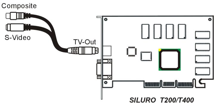
2-3. TV Output Connection (For T200/T400 Only)
The SILURO T200/T400 not only supports the VGA output to connect to PC monitor, but also supports the S-Video or TV devices connection.
Use an S-Video cable to connect from the TV-Out connector of this board to S-Video or TV devices. The next thing to do after powering on the PC and installing the driver for this board is to check the "Display Properties" → "TwinView" → "Output Device" tab to set the display mode for TV output.

Television
2-4. VGA and TV Output Connection (For T200/T400 Only)
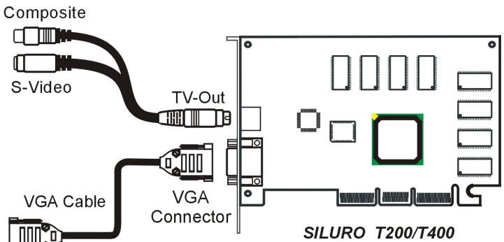
The SILURO T200/T400 supports Twin-view function of VGA and S-Video or TV devices connection,
Use the monitor's VGA cable to connect to the VGA connector of this board. Use an S-Video cable to connect from the TV-Out connector of this board to S-Video or TV devices. The next thing to do after powering on the PC and installing the driver for this board is to check the "Display Properties" → "TwinView" → "Output Device" tab to set the display mode for TV output. See the section of "Setting the display properties..." in Chapter 3 for more detail.

Television

Monitor

Chapter 3. Software Setup
You may install drivers by one of the following modes. The screen displays in this manual may not exactly reflect the screen shots on your screen. The contents of the Installation and Utility Disk (CD-Title) that came with this card are subject to change at any time without notice. The latest driver for this board is also downloadable from our WEB site at http://www.abit.com.tw.
3-1. Install Display Driver for Windows® 98
Mode 1: Auto Setup through Installation Disk
Start your Windows. Insert the installation disk into CD-ROM drive. The following screen appears:

- Click "Driver Install".

- The InstallShield Wizard appears. Click "Next".

- Click "Finish" to restart the computer.
Mode 2: Display Properties Setup

- Right-click the mouse on the desktop area, select the item "Properties".

- The "Display Properties" item appears. Select the "Settings" tab.
- Click the "Advanced..." button to go to next step.

- Click "Next".

- Click "Next".

- Type the path of the driver in the text box or use the "BBrowser" button to locate it. Click "Next".

- Click "Next".

- Click "Next".

- Click "Finish".

- Click "Yes" to restart your computer.
Mode 3: Plug and Play
- Replace the older VGA card installed in your computer with this new card.
- Start your Windows.
- Windows detects this newly installed device automatically. A New Hardware Found dialog box appears.
- Follow the on-screen instruction to install the driver.
- After the driver had been installed successfully, restart the Windows.
3-2. Install Display Driver for Windows® 2000
Mode 1: Auto Setup through Installation Disk
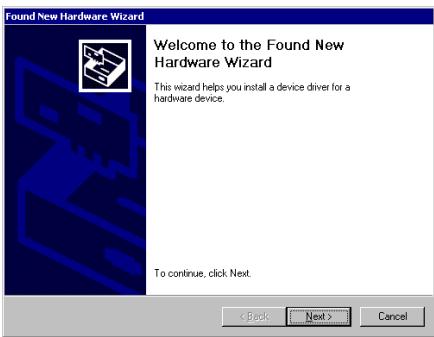
- Windows detects this new hardware automatically. Click "Cancel" to exit this wizard.

- Insert the installation disk into CD-ROM drive. Click "Driver Install".

- Click "Next".

- Click "Yes".

- Click "Finish" to restart your computer.
Mode 2: Plug and Play Setup

1. Windows detects this new hardware automatically. Click "Next".

2. Click the "Search for a suitable driver for my device [recommended]" option, and then click "Next".
![ABIT SILUROMX - Click the "Search for a suitable driver for my device [recommended]" option, and then click "Next". - 1](/content/2025/01/174583/images/8c9fcd06a71108bc1a565c7d366db1001745d8ee142292da7426cdf84a1b1071.jpg)
3. Click the "Specify a location" option, and then click "Next".

4. Insert the installation disk into CD-ROM drive. Use the "Browse..." button to locate the driver file, or type its path in the text box. Click "OK".

5. Click "Next".

6. Click "Yes".

- Click "Finish" to complete the Found New Hardware Wizard. Reboot the system.
3-3. Install WinDVD™ 2000

1. Insert the installation disk into CD-ROM drive. Click "WinDVD 2000".

2. Click "Next".
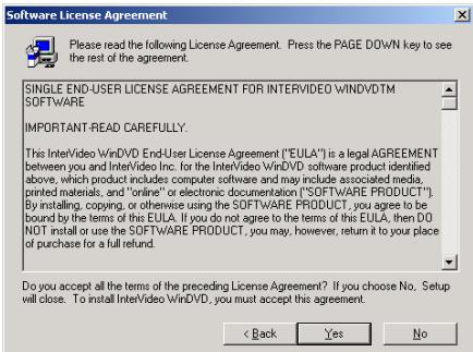
3. Click "Yes".
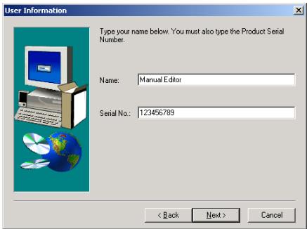
4. Type your name and the serial number of WinDVD 2000 in the text box and then click "Next".

5. Click "Next".

6. Click "Next".

7. Click "Next".
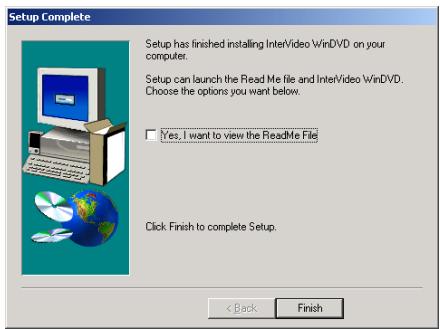
8. Click "Finish" to complete setup.

9. Click "Finish" to restart your computer.
3-4. Install DirectX
For the best gaming capability, we suggest that you install the latest DirectX driver. Some newer games will also ask you to install the DirectX driver before you start them.

1. Insert the installation disk into CD-ROM drive. Click "DirectX".
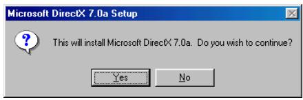
2. Click the "Yes".
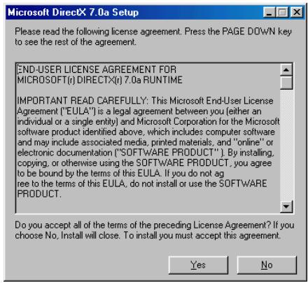
3. Click "Yes".

4. Click "OK" to restart your computer.
Chapter 4. Utility Setup
4-1. Setting Display Properties in Windows® 98 SE
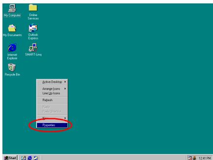
- Start the Windows. Right-click the mouse on the desktop area. Select the item "Properties" to enter "Display Properties".

- Select "Settings" tab. Click "Advanced..." button for all advanced control menus.
General

- You can choose small or large font size here, or you may choose "Other..." to go to the "Custom Font Size" screen.

- Set the font size you want. Click "OK" to enter the settings and goes back to the display properties.
Adapter

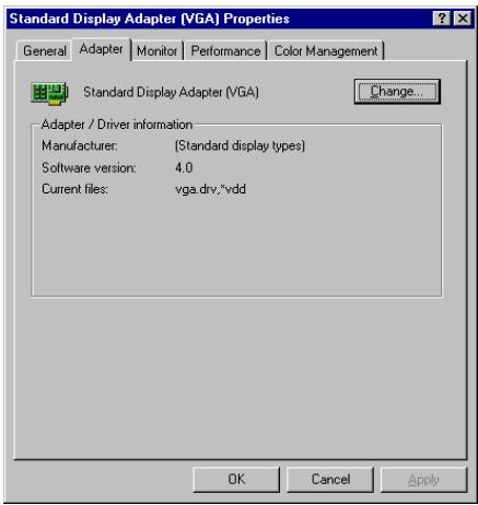
5. This tab shows the current driver information. Click "Change..." button if you want to change the driver.

6. Follow the on-screen instructions. Click "Next" to update driver.
Monitor

7. The Windows is now using the default monitor. Click "Change..." button if you want to change the monitor type.

8. Click the type that matches your monitor, and then click "OK". Click "Have Disk..." button if you want to install a new driver from disk drive.
Performance

- This tab controls how Windows would use your display adapter. This is helpful in troubleshooting the display-related problems.
Color Management
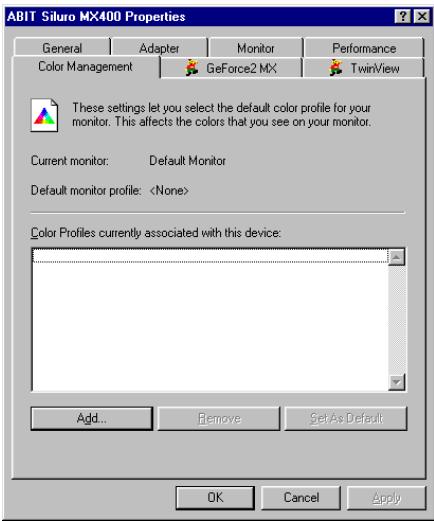
- Select the default color profile for your monitor. This will affect the colors that you see on your monitor.
The high-end or some middle-end monitors provide a color profile file to allow colors to be shown more accurately on screen. If you have such a profile disk, click the "Add..." button to add the file.

- The color profiles files appear. Select your monitor type, or put the driver disk into disk drive, and then click "Add" button to install.
GeForce2 MX

- This tab shows all the detailed information regarding your graphics card. Click "Additional Properties..." button for more settings.

13. "Direct3D Settings" tab:
■ Enable fog table emulation:
Direct3D specifies that a display adapter capable of D3D hardware acceleration should be able to implement either vertex fog or table fog. Some games do not correctly query the D3D hardware capabilities and expect table fog support. Choosing this option will ensure that such games will run properly on your NVIDIA graphics processor.
Adjust Z-buffer depth to render depth if unequal:
This will cause the hardware to automatically adjust the depth of its Z -buffer to the depth that the application requests.
Keep this option enabled, unless your work absolutely requires a specific Z-buffer depth. If this option is disabled, any application whose working Z-buffer depth does not match that of the current hardware configuration will not run.
■ Enable alternate depth buffering technique:
This option enables an alternate technique for depth buffering. It allows the hardware to use a different mechanism for depth buffering in 16 bit applications. Enabling this setting can produce higher quality renderings of 3D images.
Display logo when running Direct3D applications:
Enabling this option will display the logo of NVIDIA at the lower corner of the screen while running Direct3D applications.
- Automatically generate ....... mipmap levels:
This option allows to automatically generate mipmaps to increase the efficiency of texture transfers across the bus and provide higher applications performance.
Auto-mipmap method:
Choose bilinear method for better performance. Choose trilinear method for higher image quality.
Mipmap detail level:
This option allows you to adjust the level of detail (LOD) bias for mipmaps. A lower bias will provide better image quality, and higher bias will increase application performance. You can choose from five preset bias values from "Best image quality" to "Best performance".
Click the "More Direct3D..." button for more options on Direct3D and AntialIASing.

Texel Alignment:
This option changes the hardware texture addressing scheme for texels (texture elements).
Changing these values will adjust the texel origin definition. The default setting value is in accordance with Direct3D specifications. Some software will define the texture origin to other places. For such applications, re-defining the texture origin will improve the image quality. You can drag the slider to adjust the texel origin between the upper left corner to center of the texel.

14. Select the degree of antialIASing to be used in Direct3D.
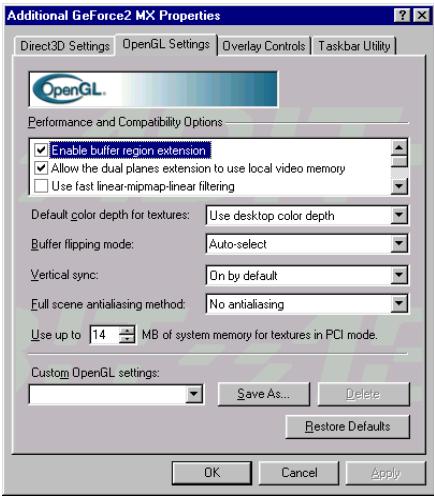
15. The "OpenGL Settings" tab allows you to adjust the image texture quality in OpenGL applications.
■ Enabled buffer region extension:
This option allows the driver to use the OpenGL extension GL_KTX_buffer_region. It can increase the application performance in 3D modeling applications that support this extension.
- Allow the dual planes extension to use local memory:
Allows the use of local video memory when the GL_KTX_buffer_region extension is enabled. However, if there are less than 8MB of local video memory available, dual planes extension support will not be enabled. This setting has no effect if the "Enable buffer region extension" option above is disabled.
Use fast linear-mipmap-linear filtering:
Allowing fast linear-mipmap-linear filtering will provide an increased application performance at the expense of some image quality. In many cases, this loss of image quality may not be noticeable, so you may wish to take advantage of the extra performance gained by enabling this feature.
■ Enable anisotropic filtering:
This option allows OpenGL to use anisotropic filtering for improved image quality.
■ Enable alternate depth buffering technique:
Enables an alternate technique for depth buffering. This lets the hardware use a different mechanism for depth buffering in 16 bit applications. Enabling this setting can produce higher quality rendering of 3D images.
- Disable support for enhanced CPU instruction sets:
Select this option to disable driver support for enhanced instructions used by certain CPUs. Some processors that support additional 3D instructions can improve performance in 3D games or applications. The Intel® MMX™ series and AMD 3D NOW!™ series processors are examples of such. If these 3D games and applications are not optimized for these enhanced instructions, the processors will have no added effect. The display driver is also needed to support these features. You can
disable this option and it may be useful for troubleshooting and performance comparison.
Default color depth for textures:
This option determines whether textures of a specific color depth should be used by default in OpenGL applications.
Use desktop color depth: This setting will always use the texture of the color depth at which your Windows desktop is currently running.
Always use 16 bpp or Always use 32 bpp: These options will force the use of textures of the specified color depth, regardless of your desktop settings.
Buffer flipping mode:
This option determines the buffer flipping mode for full-screen OpenGL applications. You can select from the block transfer method, the page flip method or auto-select. Auto-select allows the driver to determine the best method based on your hardware configuration.
Vertical sync:
This option lets you specify how vertical sync is handled in OpenGL.
Always off: This setting will always disable vertical sync in OpenGL applications.
Off by default: This setting will keep vertical sync disabled, unless an application specifically requests that it be enabled.
On by default: This setting will keep vertical sync enabled, unless an application specifically requests that it be disabled.
Use up to "xx" MB of system memory for textures in PCI mode:
This allows the graphics processor to utilize up to the specified amount of system memory for texture storage (in addition to the memory installed on the display adapter itself).
The maximum amount of system memory that can be reserved for texture storage is based on the amount of physical RAM installed in your computer. The more system RAM, the higher the value you will be able to set.
A larger value can improve the performance for some Direct3D applications. This setting applies only to PCI display adapters. If you use the AGP bus display adapter, this option will not be available (except when the AGP display adapters are running in PCI compatibility mode).
Custom OpenGL settings:
This is a list of the custom settings (or "tweaks") you have saved. Selecting an item from the list will activate the setting. To apply the setting, choose "OK" or "Apply".
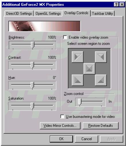
16. The "Overlay Control" tab:
Use these controls to adjust the quality of video or DVD playback on your monitor.
Brightness:
Move the slider to set the brightness level.
Contrast:
Move the slider to set the contrast level.
■Hue:
Move the slider to set the hue level.
Saturation:
Move the slider to set the saturation level.
■ Enable video overlay zoom:
Select the screen region to zoom, and then move
the slider in "Zoom control" to zoom the overlaid video.
Click the "Video Mirror Controls..." button to enter the "Full Screen Video Mirror Control".

17. Here you can control the full screen device, aspect ratio, and zoom control of the video mirror.

18. "Tackbar Utility" tab.
You can conveniently access various features and presets you have configured in the Display Properties directly from the Windows taskbar.
The icons for the taskbar are ABIT Soft Jumpy logo, monitor with blue graphics board, and monitor with red graphics board.

19. This tab allows you to connect two separate output devices (analog monitor, digital flat panel or TV) to a single graphics card.
Click "Output Device >" button for more output device selection:

20. Select the output device on which to display Windows.
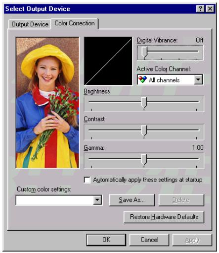
21. This tab allows you to correct brightness, contrast, and gamma values. Move the slider of Digital Vibrance Control (DVC) to deliver crisp and brighter images on screen.

22. This option allows you to adjust the centering of the monitor image.

23. This option allows you to select your monitor timing mode:
Auto-Detect: Allows Windows to receive the proper timing information directly from the monitor itself. This is the default setting. Note that some older monitors may not offer support.
General Timing Formula (GTF): This is a standard used by most newer hardware.
Discrete Monitor Timings (DMT): This is an older standard still in use on some hardware. Enable this option if your hardware requires DMT.
4-2. Setting Display Properties in Windows® 2000

- Start the Windows. Right-click the mouse on the desktop area. Select the item "Properties" to enter "Display Properties".

- Select "Settings" tab. Click "Advanced..." button. All the advanced control menu appears.
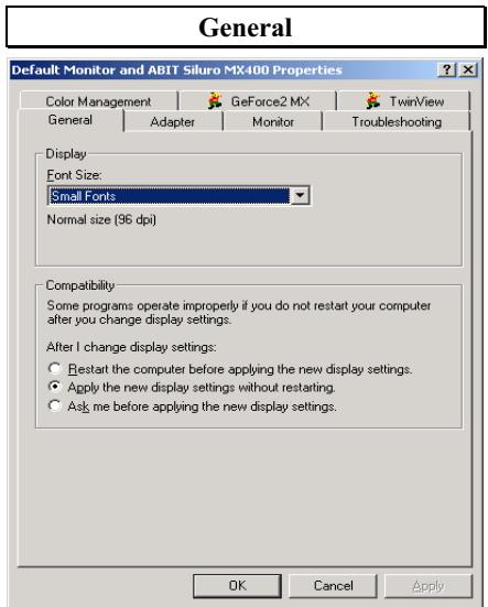
- Here you can change the display font size.

- Click "Properties" for more information on General, Driver, and Resources of this adapter.


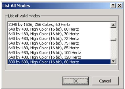
- Or click "List All Modes..." for all valid display modes.

- Select the monitor refresh frequency. Click "Properties" for more information on General and Driver of the monitor.
Troubleshooting

- Keep the hardware acceleration at full level.
Color Management
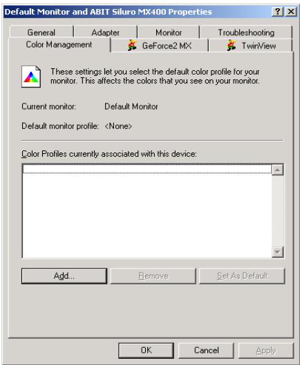
- Select the default color profile for your monitor. This will affect the colors that you see on your monitor.
The high-end or some middle-end monitors provide a color profile file with the monitor to allow the colors to be shown more accurately on the screen. If you do have such a profile disk, click the "Add..." button to add the file.

- The color profiles files appear. If your monitor type is listed here, select it directly, or put the disk into the drive and click the "Add" button to install.
GeForce2 MX
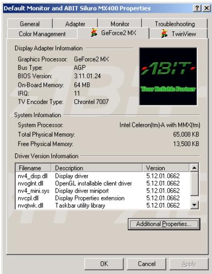
- This tab shows all the detailed information regarding your graphics card. Click "Additional Properties..." button for more settings.

11. "Direct3D Settings" tab:
Enable fog table emulation:
Direct3D specifies that a display adapter capable of D3D hardware acceleration should be able to implement either vertex fog or table fog. Some games do not correctly query the D3D hardware capabilities and expect table fog support. Choosing this option will ensure that such games will run properly on your NVIDIA graphics processor.
Adjust Z-buffer depth to render depth if unequal:
This will cause the hardware to automatically adjust the depth of its Z -buffer to the depth that the application requests.
Keep this option enabled, unless your work absolutely requires a specific Z-buffer depth. If this option is disabled, any application whose working Z-buffer depth does not match that of the current hardware configuration will not run.
■ Enable alternate depth buffering technique:
This option enables an alternate technique for depth buffering. It allows the hardware to use a different mechanism for depth buffering in 16 bit applications. Enabling this setting can produce higher quality renderings of 3D images.
Display logo when running Direct3D applications:
Enabling this option will display the logo of NVIDIA at the lower corner of the screen while running Direct3D applications.
Automatically generate ....mipmap levels:
This option allows to automatically generate mipmaps to increase the efficiency of texture transfers across the bus and provide higher applications performance.
Auto-mipmap method:
Choose bilinear method for better performance. Choose trilinear method for higher image quality.
Mipmap detail level:
This option allows you to adjust the level of detail (LOD) bias for mipmaps. A lower bias will provide better image quality, and higher bias will increase application performance. You can choose from five preset bias values from "Best image quality" to "Best performance".
Click the "More Direct3D..." button for more options on Direct3D and AntialIASing.

Texel Alignment:
This option changes the hardware texture addressing scheme for texels (texture elements).
Changing these values will adjust the texel origin definition. The default setting value is in accordance with Direct3D specifications. Some software will define the texture origin to other places. For such applications, re-defining the texture origin will improve the image quality. You can drag the slider to adjust the texel origin between the upper left corner to center of the texel.

12. Select the degree of antialiasing to be used in Direct3D.

13. The "OpenGL Settings" tab allows you to adjust the image texture quality in OpenGL applications.
■ Enabled buffer region extension:
This option allows the driver to use the OpenGL extension GL_KTX_buffer_region. It can increase the application performance in 3D modeling applications that support this extension.
- Allow the dual planes extension to use local memory:
Allows the use of local video memory when the GL_KTX_buffer_region extension is enabled. However, if there are less than 8MB of local video memory available, dual planes extension support will not be enabled. This setting has no effect if the "Enable buffer region extension" option above is disabled.
Use fast linear-mipmap-linear filtering:
Allowing fast linear-mipmap-linear filtering will provide an increased application performance at the expense of some image quality. In many cases, this loss of image quality may not be noticeable, so you may wish to take advantage of the extra performance gained by enabling this feature.
■ Enable anisotropic filtering:
This option allows OpenGL to use anisotropic filtering for improved image quality.
■ Enable alternate depth buffering technique:
Enables an alternate technique for depth buffering. This lets the hardware use a different mechanism for depth buffering in 16 bit applications. Enabling this setting can produce higher quality rendering of 3D images.
- Disable support for enhanced CPU instruction sets:
Select this option to disable driver support for enhanced instructions used by certain CPUs. Some processors that support additional 3D instructions can improve performance in 3D games or applications. The Intel® MMX™ series and AMD 3D NOW!™ series processors are examples of such. If these 3D games and applications are not optimized for these enhanced instructions, the processors will have no added effect. The display driver is also needed to support these features. You can
disable this option and it may be useful for troubleshooting and performance comparison.
Default color depth for textures:
This option determines whether textures of a specific color depth should be used by default in OpenGL applications.
Use desktop color depth: This setting will always use the texture of the color depth at which your Windows desktop is currently running.
Always use 16 bpp or Always use 32 bpp: These options will force the use of textures of the specified color depth, regardless of your desktop settings.
Buffer flipping mode:
This option determines the buffer flipping mode for full-screen OpenGL applications. You can select from the block transfer method, the page flip method or auto-select. Auto-select allows the driver to determine the best method based on your hardware configuration.
Vertical sync:
This option lets you specify how vertical sync is handled in OpenGL.
Always off: This setting will always disable vertical sync in OpenGL applications.
Off by default: This setting will keep vertical sync disabled, unless an application specifically requests that it be enabled.
On by default: This setting will keep vertical sync enabled, unless an application specifically requests that it be disabled.
Use up to "XX" MB of system memory for textures in PCI mode:
This allows the graphics processor to utilize up to the specified amount of system memory for texture storage (in addition to the memory installed on the display adapter itself).
The maximum amount of system memory that can be reserved for texture storage is based on the amount of physical RAM installed in your computer. The more system RAM, the higher the value you will be able to set.
A larger value can improve the performance for some Direct3D applications. This setting applies only to PCI display adapters. If you use the AGP bus display adapter, this option will not be available (except when the AGP display adapters are running in PCI compatibility mode).
Custom OpenGL settings:
This is a list of the custom settings (or "tweaks") you have saved. Selecting an item from the list will activate the setting. To apply the setting, choose "OK" or "Apply".

14. The "Overlay Color Control" tab:
Use these controls to adjust the quality of video or DVD playback on your monitor.
Brightness:
Move the slider to set the brightness level.
Contrast:
Move the slider to set the contrast level.
■ Hue:
Move the slider to set the hue level.
Saturation:
Move the slider to set the saturation level.

15. "Other Options" tab:
Monitor Timing:
This option allows you to select your monitor timing mode:
Auto-Detect: Allows Windows to receive the proper timing information directly from the monitor itself. This is the default setting. Note that some older monitors may not offer support.
General Timing Formula (GTF): This is a standard used by most newer hardware.
Discrete Monitor Timings (DMT): This is an older standard still in use on some hardware. Enable this option if your hardware requires DMT.

- This TwinView tab allows you to connect two separate output devices (analog monitor, digital flat panel or TV) to a single graphics card.
Click "Output Device >" button for more output device selection:

- Select the output device on which to display on Windows.

- This tab allows you to correct brightness, contrast, and gamma values. Move the slider of Digital Vibrance Control (DVC) to deliver crisp and brighter images on screen.

- This option allows you to adjust the centering of the monitor image.
4-3. The Graphic Max
We have provided you with a tool for adjusting both the graphic processors working speed and the graphic memory speed. Please be reminded that it may cause damage to both the graphic processor and graphic memory if you use incorrect settings. Please read the following description carefully before running Graphic Max!
Important Warning Message
ABIT does not provide any warranty or support for this utility. The usage of this utility is at your own risk. This risk includes all damages caused by this utility. If you don't accept this warning, don't use this utility.
ABIT does not recommend any overclocking settings for your hardware. Overclocking can cause overheating which will damage your chip.
If you are not acquainted with the display card hardware, we strongly recommend that you not to use this utility. Improper settings can cause unrecoverable damages to your graphics chip, your display card, and other components!
Application Notes
This utility is provided for fine-tuning your display card to allow for maximum stability on your system. It is for Windows® 98/ME only.
Select "Start → Programs → ABIT Graphic Max → Graphic Max" to launch Graphic Max.
If you have adjusted the Graphic Max settings and have problems after booting, you can boot into "Windows Safe Mode" and then run "Start → Programs → ABIT Graphic Max → Graphic Max Safe Mode Recovery" to clear previous settings.

1. Insert the installation disk into CD-ROM drive. Click "VGA Utility".

2. Click "Graphic Max".
Follow each installation procedure shown on your screen. The software can be installed quite easily in this way.
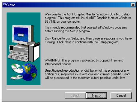
3. Click "Next".

4. Click "Next".
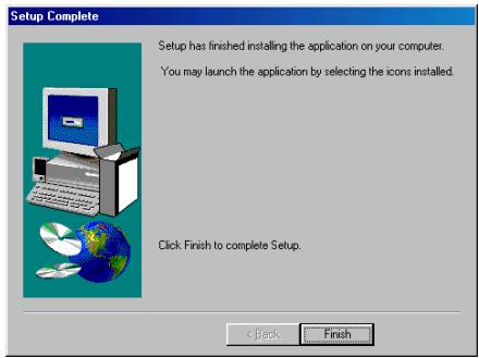
5. Click "Finish" to complete the setup.
Select "Start → Programs → ABIT Graphic Max → Graphic Max" to launch Graphic Max.
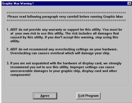
6. Each time you execute the program, you will see this warning message screen. Please read the entire message and then click "Agree" button to go on.

7. When the Graphic Max screen appears, you can use the two sliders to adjust the "Core Clock Frequency" and the "Memory Clock Frequency". Please adjust these values very carefully.
4-4. The 3Deep Color
The 3Deep Color is a software utility to correct lighting, shading and color for all your 2D and 3D games. You get more realistic graphics and better effects, plus a "see first, shoot first" advantage over your online competitors. Finally, you can take your hands off your monitor controls and put them back where they belong -- on the warm trigger of your laser-sighted rocket launcher.

1. Insert the installation disk into CD-ROM drive. Click "VGA Utility".
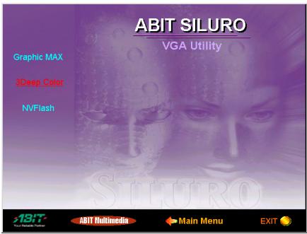
2. Click "3Deep Color".

3. Click "Next".
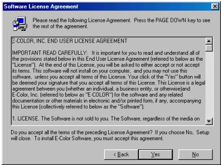
4. Click "Yes".

5. Click "Next".
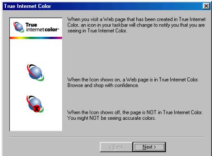
6. Click "Next".

7. Click "Next".
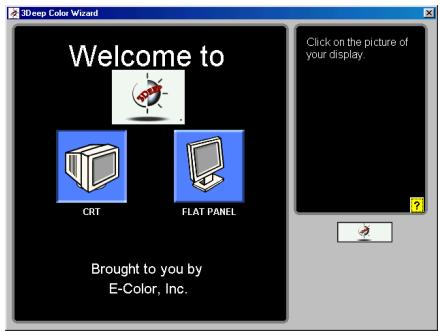
8. The 3Deep Color Wizard appears. Click on the picture of your display type as CRT or Flat Panel.

9. Set the brightness control of your monitor to maximum, and then reduce the brightness control until the farthest monster image disappears.

10. Click on the blue, red, and green patches where you see just a hint of color. Do not change the monitor brightness now.

11. Click on the blue, red, and green square that appears to be blend into the background.
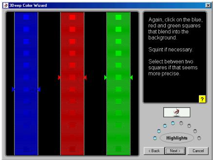
12. Click on the blue, red, and green square that appears to be blend into the background.
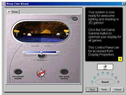
13. Click "Finish" to end the 3Deep Color setup.

14. Click "Set Up Now!" to set up True Internet Color.

15. This tab explains the meaning of each different icon appears in the taskbar.

16. Tune up the Internet Color in this tab.

17. This tab indicates the WEB site of E-Color, and the version of the True Internet Color.
4-5. Display Tray Icon
After installation of display drivers, you will find a display tray icon on the taskbar's status area. Clicking or right-clicking this icon opens the Display Tray, a function shortcut of this graphics accelerator.
Note
Besides clicking this display tray icon to control the display properties, another way to do this is to right-click the Windows desktop area, click Properties → Settings → Advanced, and then click the appropriate tab to change your display settings.

- Right-click this display tray icon on the taskbar's status area.

- A menu pop up. Move the cursor to "More Resolution" item to see the entire resolution table. Here you can directly choose the display resolution you want.

- If you want to change the refresh rate of display adapter, move cursor to "Refresh Rate", here you can directly choose the display refresh rate you want.
Make sure your display monitor supports the higher refresh rate you choose; otherwise, your monitor may not display normally. Please refer to your display monitor user's manual for detailed specifications.
Click "Windows Display Properties..." to start setting up your display properties.
- Choose "Exit" to leave this program.
4-6. BIOS Flashing Utility
You may update the newest SILURO™ MX200/MX400/T200/T400 drivers or BIOS files from your dealer or directly download from our WEB site at http://www.abit.com.tw.
Note
When you use the flash utility to flash the BIOS, the screen will be blank for about 20~25 seconds. This is a normal situation, not a malfunction. Do not reboot your computer during this period, or you may cause the flash to fail.
Step 1. Reboot your computer into DOS environment, or open a Windows® 95/98 window to the DOS prompt.
Step 2. Insert the Installation CD into your CD-ROM drive.
Step 3. Copy DOS4GW.EXE and NVFLASH.EXE to a new directory from path D:\NVFLASH. (D: refers to the CD-ROM drive letter)
Step 4. Copy the new BIOS binary file to the new directory.
Step 5. Change to the new directory and type the following command: NVFLASH -F[Filename]. ([Filename] refers to the name of BIOS binary file.) Then press the "Enter" key. The program will begin flashing your display card BIOS.
Step 6. When the flash is complete (the screen will display images again), you must reboot your computer system to make flash take effect.
The following commands are for the NVIDIA Flash ROM programming utility V3.18, for your reference only.
NVIDIA Flash ROM utility v03.18 Commands List:
Example of use: NVFLASH -s4 -fBIOS.ROM -1
| -f<filename> | Flash the ROM using <filename>, then do compare and ~CRC32. |
| <filename> | Same as -f, but forces confirmation. |
| -b<filename> | Read ROM and save to <filename>. |
| -k<filename> | Read ROM and compare with <filename>. |
| -x<filename> | Xfer TV data from file to AT29LV512; SST29LE/VE512 SST39VF512. |
| -v<filename> | Display file version and ~CRC32 (if no filename, acts on ROM). |
| -t | Display 256 bytes of ROM, at offset C000h |
| -e | Erase the ROM. |
| -d | Display 256 bytes of ROM, at offset 0. |
| -c | Check for supported EEPROM. |
| -l | Don't light keyboard LEDs. |
| -p | Don't pause if ROMfile & chip PCI VenID, DevID mismatch. |
| -u | Don't pause if ROMfile & chip PCI subsystem ID mismatch. |
| -h | Reboot the PC after other tasks completed. |
| -w | Write protect ROM (only works on some ROMs). |
| -r | Remove ROM Write protect. (only works on some ROMs). |
| -a | List all supported device indexes. |
| -g<deviceid> | Force a specific device index. |
| -i<instance> | Force specific device instance (use with -g). |
| -? | Display this screen. |
| -s# | Silence level: |
| default | All progress messages, all beeps. |
| #=1 | No progress messages, no beeps. |
| #=2 | No progress messages, no progress beeps. |
| #=3 | No progress messages. |
| #=4 | No progress beeps. |
| #=5 | No beeps. |
NVFLASH supports these EEPROMs:
| SST | 29EE512 | 64Kx8 | 5.0V, | 128B page, | 0k blk, | Man,Dev=(BF,5D) |
| SST | 29LE/VE512 | 64Kx8 | 2.9,2.7V, | 128B page, | 0k blk, | Man,Dev=(BF,3D) |
| SST | 29EE010 | 128Kx8 | 5.0V, | 128B page, | 0k blk, | Man,Dev=(BF,07) |
| SST | 29LE/VE010 | 128Kx8 | 2.9,2.7V, | 128B page, | 0k blk, | Man,Dev=(BF,08) |
| SST | 39VF512 | 64Kx8 | 2.7-3.6V, | 1B page, | 4k blk, | Man,Dev=(BF,D4) |
| SST | 39VF010 | 128Kx8 | 2.7-3.6V, | 1B page, | 4k blk, | Man,Dev=(BF,D5) |
| SST | 39SF010 | 128Kx8 | 5.0V, | 1B page, | 4k blk, | Man,Dev=(BF,B5) |
| SST | 29EE020 | 256Kx8 | 5.0V, | 128B page, | 0k blk, | Man,Dev=(BF,10) |
| SST | 29LE/VE020 | 256Kx8 | 2.9,2.7V, | 128B page, | 0k blk, | Man,Dev=(BF,12) |
| SST | 39VF020 | 256Kx8 | 2.7-3.6V, | 1B page, | 4k blk, | Man,Dev=(BF,D6) |
| Atmel | 29C512 | 64Kx8 | 5.0V, | 128B page, | 0k blk, | Man,Dev=(1F,5D) |
| Atmel | 29C010A | 128Kx8 | 5.0V, | 128B page, | 0k blk, | Man,Dev=(1F,D5) |
| Atmel | 29LV512 | 64Kx8 | 3.0V, | 128B page, | 0k blk, | Man,Dev=(1F,3D) |
| Atmel | 29LV/BV010A | 128Kx8 | 3.0V, | 128B page, | 0k blk, | Man,Dev=(1F,35) |
| Atmel | 49F512 | 64Kx8 | 5.0,3.0,2.7V, | 1B page, | 0k blk, | Man,Dev=(1F,03) |
| Atmel | 49F001 | 128Kx8 | 5.0V, | 1B page, | 0k blk, | Man,Dev=(1F,05) |
| Atmel | 49F001T | 128Kx8 | 5.0V, | 1B page, | 0k blk, | Man,Dev=(1F,04) |
| Atmel | 49F010 | 128Kx8 | 5.0V, | 1B page, | 0k blk, | Man,Dev=(1F,87) |
| Atmel | 49(H)BV/LV01 | 128Kx8 | 2.7-3.6V, | 1B page, | 0k blk, | Man,Dev=(1F,17) |
| Atmel | 49LV_BV002 | 256Kx8 | 3.0,2.7V, | 1B page, | 0k blk, | Man,Dev=(1F,07) |
| Atmel | 49LV_BV002T | 256Kx8 | 3.0,2.7V, | 1B page, | 0k blk, | Man,Dev=(1F,07) |
| Atmel | 49F_LV_BV020 | 256Kx8 | 5.0,3.0,2.7V, | 1B page, | 0k blk, | Man,Dev=(1F,0B) |
| Atmel | 29F_LV_BV020 | 256Kx8 | 5.0,3.0,2.7V, | 1B page, | 0k blk, | Man,Dev=(1F,BA) |
| AMD | 29LV010 | 128Kx8 | 2.7vV, | 1B page, | 16k blk, | Man,Dev=(01,6E) |
| AMD | 29LV001T | 128Kx8 | 2.7vV, | 1B page, | 16k blk, | Man,Dev=(01,ED) |
| AMD | 29LV001B | 128Kx8 | 2.7vV, | 1B page, | 16k blk, | Man,Dev=(01,6D) |
| MX | 29F001T | 128Kx8 | 5.0V, | 1B page, | 0k blk, | Man,Dev=(C2,18) |
| MX | 29F001B | 128Kx8 | 5.0V, | 1B page, | 0k blk, | Man,Dev=(C2,19) |
| ST | M29W512B | 64Kx8 | 2.7-3.6V, | 1B page, | 0k blk, | Man,Dev=(20,27) |
| WBond | W29EE512 | 64Kx8 | 5.0V, | 128B page, | 0k blk, | Man,Dev=(DA,C8) |
| PMC | 39LV512R | 64Kx8 | 3.0-3.6V, | 1B page, | 0k blk, | Man,Dev=(9D,1B) |
| PMC | 39LV010R | 128Kx8 | 3.0-3.6V, | 1B page, | 0k blk, | Man,Dev=(9D,1C) |
| PMC | 29F002 | 256Kx8 | 3.0-3.6V, | 1B page, | 4k blk, | Man,Dev=(9D,1D) |
Appendix A. Display Modes Table
The table below is for your reference only. The display mode will differ depending on your specific monitor, and the resulting display may not be identical to this table.
| Resolution | Colors | Vertical Refresh Rate |
| 640x480 | 8/16/32 bits | 60Hz to 240Hz |
| 800x600 | 8/16/32 bits | 60Hz to 240Hz |
| 1024x768 | 8/16 bits | 60Hz to 240Hz |
| 1024x768 | 32 bits | 60Hz to 200Hz |
| 1152x864 | 8/16 bits | 60Hz to 200Hz |
| 1152x864 | 32 bits | 60Hz to 170Hz |
| 1280x960 | 8/16 bits | 60Hz to 170Hz |
| 1280x960 | 32 bits | 60Hz to 150Hz |
| 1280x1024 | 8/16 bits | 60Hz to 170Hz |
| 1280x1024 | 32 bits | 60Hz to 150Hz |
| 1600x900 | 8/16 bits | 60Hz to 150Hz |
| 1600x900 | 32 bits | 60Hz to 120Hz |
| 1600x1200 | 8/16 bits | 60Hz to 120Hz |
| 1600x1200 | 32 bits | 60Hz to 100Hz |
| 1920x1080 | 8/16 bits | 60Hz to 100Hz |
| 1920x1080 | 32 bits | 60Hz to 85Hz |
| 1920x1200 | 8/16 bits | 60Hz to 100Hz |
| 1920x1200 | 32 bits | 60Hz to 85Hz |
| 1920x1440 | 8/16 bits | 60Hz to 85Hz |
| 1920x1440 | 32 bits | 60Hz to 75Hz |
| 2048x1536 | 8/16 bits | 60Hz to 75Hz |
| 2048x1536 | 32 bits | 60Hz |

Appendix B. Product FAQ
We have collected some frequently asked questions and answers for your reference, for further help with problems or questions, please see the "How to get technical support" in Appendix C.
Q1. What driver should I use for my SILURO™ GF2 MX product?
You can begin with the driver provided by ABIT in the package your card came in for maximum performance. However, NVIDIA™ does provide updated reference drivers ("Detonator" drivers) on their web site. Please keep in mind that since NVIDIA™ does not sell products directly to the consumer, they do not have a customer support team to answer your questions.
Q2. What's APIs does the SILURO™ GF2 MX support?
It will support 2D and 3D industry standard APIs, which include: DirectX and OpenGL. It will not support proprietary APIs.
Q3. What if my application uses an API not supported by SILURO™ GF2 MX?
It means the game will switch to software rendering mode rather than utilize hardware acceleration.
Q4. Why can't run Glide with my SILURO™ GF2 MX product?
Glide is a proprietary API and only applies to a small number of games. Over 90% of software developers will develop to one of the industry standard APIs.
Q5. What is a GPU?
GPU is an acronym for "graphics processing unit." A GPU is a single-chip processor with integrated transform, lighting, triangle setup/clipping and rendering engines that is capable of producing a minimum of 10 million polygons per second.
Q6. What is the GPU's impact on the PC industry?
The GPU brings a major discontinuity in performance and image fidelity, and will fundamentally change the PC industry forever. 3D applications will never be the same.
Q7. Will I see any difference in performance when SILURO™ GF2 MX runs existing games?
YES! Current games and applications will benefit from SILURO™ GF2 MX's higher fill rate, especially in resolutions 1024 x 768 and higher.
Q8. Is the performance of SILURO™ GF2 MX CPU-dependent?
SILURO™ GF2 MX provides high-performance graphics with any CPU. In addition, SILURO™ GF2 MX's integrated transform and lighting engines allow developers to increase geometry complexity without the performance penalty. Developers can now take full advantage of the CPU horsepower to apply more realistic physics, artificial intelligence, and game play.
Q9. Can SILURO™ GF2 MX's integrated T&L engines be used with Microsoft® DirectX® 7?
Yes. The SILURO™ GF2 MX and DirectX® 7 were designed in conjunction so that maximum performance and compatibility could be achieved.
Q10. If the SILURO™ GF2 MX offloads the host CPU from performing the T&L calculations, what will be left for the CPU?
By offloading the T&L computations, the CPU will now have the bandwidth to dramatically improve the level of quality for physics, artificial intelligence and character animation.
Q11. Is DirectX® 7 required to take advantage of SILURO™ GF2 MX's T&L engines?
No. Hardware T&L can be used with OpenGL or DirectX 7.
Q12. Does it support texture compression?
Yes. SILURO™ GF2 MX supports all five formats of DX6 texture compression.
Q13. What kind of bump mapping does SILURO™ GF2 MX support?
SILURO™ GF2 MX supports single-pass emboss and dot-product bump mapping. With its integrated T&L geometry power, SILURO™ GF2 MX will enable much more realistic "bump" effects without sacrificing performance.
Q14. My MPEG player displays poor quality video images, why?
First, you have to check your system had installed DirectX® 6 or later version, so that your MPEG player can take advantage of the hardware acceleration mode (DirectDraw).
Second, you can try to lower your display resolution, color depth, or refresh rate. Because this will allow your MPEG player to use hardware acceleration mode.
Third, switch your display mode to VGA or TV, then see if the video quality which one is better.
Q15. My games or applications report "No 3d acceleration hardware found."
Normally, 3D mode works only in 16-bit or 32-bit color depth. Change your color depth to 16-bit (high color). Also check the DirectX or OpenGL libraries installed complete, or you can try to change to a lower display resolution.
Q16. DirectX or applications report "No AGP memory available".
Your Windows® 95 is not OSR2.1 or later version, or your DirectX version is not version 6.0 or later. Some AGP chipset need to installed appropriate drivers, otherwise it will not work well. Also check your motherboard BIOS for AGP aperture size, it must support at least 64MB for AGP aperture size.
Q17. How to Get Technical Support
If you encounter any problems and need help from our technical staff, please take the time to fill out the Technical Support Form and send it to your dealer or our technical support mailbox. The mailbox address is: technical@abit.com.tw. We will try to solve your problem as soon as possible. You must provide specific information on your equipment. Also please describe in detail the problems you encountered. It's helpful and enables our technicians to analyze your problems more quickly.
Information on items marked with an asterisk ** on the Technical Support Form are required.

Technical Support Form
Company Name:
Phone Number:
Contact Person:
Fax Number:
E-mail Address:
| VGA Card Product Name | * | VGA Card BIOS Version | * |
| Motherboard Manufacturer, Model Name and Chipset type | * | VGA Card Software and Driver Version | * |
| Operating System Type | * | Monitor Manufacturer and Model | * |
| Hardware name | Type | Specifications | |
| CPU Type and Speed | * | ||
| HDD IDE1IDE2 | |||
| CD-ROM IDE1Drive IDE2 | |||
| System Memory Size (SDRAM) | * | ||
| Add-On Card | * | ||
Problem Description:

Appendix C. How to Get Technical Support
(From our website) http://www.abit.com.tw
(In North America) http://www.abit-usa.com
(In Europe) http://www.ubit.nl
Thank you for choosing ABIT products. ABIT sells all our products through distributors, resellers and system integrators, we have no direct sales to end-users. Before sending email for tech support please check with your resellers or integrators if you need any services, they are the ones who sold you your system and they should know best as to what can be done, how they serve you is a good reference for future purchases.
We appreciate every customer and would like to provide the best service to you. Providing fast service to our customers is our top priority. However we receive many phone calls and a huge amount of email from all over the world. At the present time it is impossible for us to respond to every single inquiry. Therefore it is quite possible that if you send an email to us that you may not receive a response.
We have done many compatibility tests and reliability tests to make sure our products have the best quality and compatibility. In case you need service or technical support, please understand the constraint we have and always check with the reseller who sold the product to you first.
To expedite service, we recommend that you follow the procedures outlined below before contacting us. With your help, we can meet our commitment to provide the best service to the greatest number of ABIT customers:
- Check the Manual. It sounds simple but we have taken a lot of care in making a well-written and thorough manual. It is full of information that doesn't only pertain to motherboards. The CD-ROM included with your board will have the manual as well as drivers. If you don't have either one go to our Program Download Area of the Website or FTP server at: http://www.abit.com.tw/download/index.htm
- Download latest BIOS, software or drivers. Please go to our Program Download area on our Website to check to see if you have the latest BIOS. They are developed over periods of time to fixes bugs or incompatibilities. Also please make sure you have the latest drivers from your peripheral cards makers!
-
Check the ABIT Technical Terms Guide and FAQ on our Website. We are trying to expand and make the FAQs more helpful and information rich. Let us know if you have any suggestions. For hot topics check out our HOT FAQ!
-
Internet Newsgroups. They are a great source of information and many people there can offer help. ABIT's Internet News group, alt.comp.perips.mainboard.abit, is an ideal forum for the public to exchange information and discuss experiences they have had with ABIT products. Many times you will see that your question has already been asked before. This is a public Internet news group and it is reserved for free discussions. Here is a list of some of the more popular ones:
alt.comp.perips.mainboard.abit
comp.sysibm.pc.hardware.chips
alt.comp.hardware.overclocking
alt.comp.hardware.homebuilt
alt.comp.hardware.pc-homebuilt
- Ask your reseller. Your ABIT authorized distributor should be able to provide the fastest solution to your technical problem. We sell our products through distributors who sell to resellers and stores. Your reseller should be very familiar with your system configuration and should be able to solve your problem much more efficiently than we could. After all, your reseller regards you as an important customer who may purchase more products and who can urge your friends to buy from him or her as well. They integrated and sold the system to you. They should know best what your system configuration is and your problem. They should have reasonable return or refund policies. How they serve you is also a good reference for your next purchase.
- Contacting ABIT. If you feel that you need to contact ABIT directly you can send email to the ABIT technical support department. First, please contact the support team for the branch office closest to you. They will be more familiar with local conditions and problems and will have better insight as to which resellers offer what products and services. Due to the huge number of emails coming in every day and other reasons, such as the time required for problem reproduction, we will not be able to reply to every email. Please understand that we are selling through distribution channels and don't have the resources to serve every end-user. However, we will try to do our best to help every customer. Please also remember that for many of our technical support team English is a second language, you will have a better chance of getting a helpful answer if your question can be understood in the first place. Be sure to use very, simple, concise language that clearly states the problem, avoid rambling or flowery language and always list your system components. Here is the contact information for our branch offices:
In North America and South America please contact:
ABIT Computer (USA) Corporation
46808 Lakeview Blvd.
Fremont, California 94538, U.S.A.
sales@abit-usa.com
technical@abit-usa.com
Tel: 1-510-623-0500
Fax: 1-510-623-1092
In the UK and Ireland:
ABIT Computer Corporation Ltd.
Unit 3, 24-26 Boulton Road
Stevenage, Herts SG1 4QX, UK
abituksales@compuserve.com
abituktech@compuserve.com
Tel: 44-1438-228888
Fax: 44-1438-226333
In Germany and Benelux (Belgium, Netherlands, Luxembourg) countries:
AMOR Computer B.V. (ABIT's European Office)
Van Coehoornstraat 7,
5916 PH Venlo, The Netherlands
sales@abit.nl
technical@abit.nl
Tel: 31-77-3204428
Fax: 31-77-3204420
All other territories not covered above please contact:
Taiwan Head Office
When contacting our headquarters please note we are located in Taiwan and we are 8+ GMT time. In addition, we have holidays that may be different from those in your country.
ABIT Computer Corporation
3F-7, No. 79, Sec. 1, Hsin Tai Wu Rd.
Hsi Chi, Taipei Hsien, Taiwan
sales@abit.com.tw
market@abit.com.tw
technical@abit.com.tw
Tel: 886-2-2698-1888
Fax: 886-2-2698-1811
- RMA Service. If your system has been working but it just stopped, but you have not installed any new software or hardware recently, it is likely that you have a defective component. Please contact the reseller from whom you bought the product. You should be able to get RMA service there.
- Reporting Compatibility Problems to ABIT. Because of tremendous number of email messages we receive every day, we are forced to give greater weight to certain types of messages than to others. For this reason, any compatibility problem that is reported to us, giving detailed system configuration information and error symptoms will receive the highest priority. For the other questions, we regret that we may not be able to reply directly. But your questions may be posted to the Internet news group in order that a larger number of users can have the benefit of the information. Please check the news group from time to time.
Thank you, ABIT Computer Corporation http://www.abit.com.tw
- COPYRIGHT AND WARRANTY NOTICE
- SILURO™ MX200/MX400/T200/T400 GRAPHICS ACCELERATOR
- CHAPTER 1. INTRODUCTION 1-1
- CHAPTER 2. HARDWARE SETUP 2-1
- CHAPTER 3. SOFTWARE SETUP 3-1
- CHAPTER 4. UTILITY SETUP. 4-1
- APPENDIX A. DISPLAY MODES TABLE
- APPENDIX B. PRODUCT FAQ
- APPENDIX C. HOW TO GET TECHNICAL SUPPORT
- CHAPTER 1. INTRODUCTION
- 1-1. FEATURES
- 1-2. SPECIFICATIONS OF MX200/T200
- NVIDIA GEFORCE2 MX200 2D AND 3D GRAPHICS ACCELERATOR
- TV-OUT (FOR T200 ONLY)
- HIGH QUALITY DVD PLAYBACK
- 1-3. SPECIFICATIONS OF MX400/T400
- NVIDIA GEFORCE2 MX400 2D AND 3D GRAPHICS ACCELERATOR
- TV-OUT (FOR T400 ONLY)
- 1-4. FEATURES AND BENEFITS
- 1-5. LAYOUT DIAGRAM
- CHAPTER 2. HARDWARE SETUP
- 2-1. CARD INSTALLATION
- NEW SYSTEMS
- SYSTEMS WITH EXISTING VGA CARD
- 2-2. VGA OUTPUT CONNECTION
- 2-3. TV OUTPUT CONNECTION (FOR T200/T400 ONLY)
- 2-4. VGA AND TV OUTPUT CONNECTION (FOR T200/T400 ONLY)
- CHAPTER 3. SOFTWARE SETUP
- 3-1. INSTALL DISPLAY DRIVER FOR WINDOWS® 98
- MODE 1: AUTO SETUP THROUGH INSTALLATION DISK
- MODE 2: DISPLAY PROPERTIES SETUP
- MODE 3: PLUG AND PLAY
- 3-2. INSTALL DISPLAY DRIVER FOR WINDOWS® 2000
- MODE 2: PLUG AND PLAY SETUP
- WINDOWS DETECTS THIS NEW HARDWARE AUTOMATICALLY. CLICK "NEXT
- CLICK THE "SEARCH FOR A SUITABLE DRIVER FOR MY DEVICE [RECOMMENDED]" OPTION, AND THEN CLICK "NEXT
- CLICK THE "SPECIFY A LOCATION" OPTION, AND THEN CLICK "NEXT
- INSERT THE INSTALLATION DISK INTO CD-ROM DRIVE. USE THE "BROWSE..." BUTTON TO LOCATE THE DRIVER FILE, OR TYPE ITS PATH IN THE TEXT BOX. CLICK "OK
- CLICK "NEXT
- CLICK "YES
- 3-3. INSTALL WINDVD™ 2000
- CLICK "FINISH" TO COMPLETE SETUP
- CLICK "FINISH" TO RESTART YOUR COMPUTER
- 3-4. INSTALL DIRECTX
- CHAPTER 4. UTILITY SETUP
- 4-1. SETTING DISPLAY PROPERTIES IN WINDOWS® 98 SE
- GENERAL
- ADAPTER
- MONITOR
- PERFORMANCE
- COLOR MANAGEMENT
- GEFORCE2 MX
- ENABLE FOG TABLE EMULATION
- ADJUST Z-BUFFER DEPTH TO RENDER DEPTH IF UNEQUAL
- ENABLE ALTERNATE DEPTH BUFFERING TECHNIQUE
- DISPLAY LOGO WHEN RUNNING DIRECT3D APPLICATIONS
- AUTOMATICALLY GENERATE ....... MIPMAP LEVELS
- AUTO-MIPMAP METHOD
- MIPMAP DETAIL LEVEL
- TEXEL ALIGNMENT
- ENABLED BUFFER REGION EXTENSION
- ALLOW THE DUAL PLANES EXTENSION TO USE LOCAL MEMORY
- USE FAST LINEAR-MIPMAP-LINEAR FILTERING
- ENABLE ANISOTROPIC FILTERING
- DISABLE SUPPORT FOR ENHANCED CPU INSTRUCTION SETS
- DEFAULT COLOR DEPTH FOR TEXTURES
- BUFFER FLIPPING MODE
- VERTICAL SYNC
- USE UP TO "XX" MB OF SYSTEM MEMORY FOR TEXTURES IN PCI MODE
- CUSTOM OPENGL SETTINGS
- THE "OVERLAY CONTROL" TAB
- BRIGHTNESS
- CONTRAST
- HUE
- SATURATION
- ENABLE VIDEO OVERLAY ZOOM
- 4-2. SETTING DISPLAY PROPERTIES IN WINDOWS® 2000
- TROUBLESHOOTING
- AUTOMATICALLY GENERATE ....MIPMAP LEVELS
- THE "OVERLAY COLOR CONTROL" TAB
- MONITOR TIMING
- 4-3. THE GRAPHIC MAX
- IMPORTANT WARNING MESSAGE
- APPLICATION NOTES
- 4-4. THE 3DEEP COLOR
- 4-5. DISPLAY TRAY ICON
- NOTE
- 4-6. BIOS FLASHING UTILITY
- EXAMPLE OF USE: NVFLASH -S4 -FBIOS.ROM -1
- TECHNICAL SUPPORT FORM
- IN NORTH AMERICA AND SOUTH AMERICA PLEASE CONTACT
- ABIT COMPUTER (USA) CORPORATION
- IN THE UK AND IRELAND
- ABIT COMPUTER CORPORATION LTD
- IN GERMANY AND BENELUX (BELGIUM, NETHERLANDS, LUXEMBOURG) COUNTRIES
- AMOR COMPUTER B.V. (ABIT'S EUROPEAN OFFICE)
- ALL OTHER TERRITORIES NOT COVERED ABOVE PLEASE CONTACT
- TAIWAN HEAD OFFICE
- ABIT COMPUTER CORPORATION
- THANK YOU, ABIT COMPUTER CORPORATION HTTP://WWW.ABIT.COM.TW
Marque : ABIT
Modèle : SILUROMX
Catégorie : Carte graphique