M465 - Injecteur d'air Coburn - Notice d'utilisation et mode d'emploi gratuit
Retrouvez gratuitement la notice de l'appareil M465 Coburn au format PDF.


Questions des utilisateurs sur M465 Coburn
0 question sur cet appareil. Repondez a celles que vous connaissez ou posez la votre.
Poser une nouvelle question sur cet appareil
Téléchargez la notice de votre Injecteur d'air au format PDF gratuitement ! Retrouvez votre notice M465 - Coburn et reprennez votre appareil électronique en main. Sur cette page sont publiés tous les documents nécessaires à l'utilisation de votre appareil M465 de la marque Coburn.
MODE D'EMPLOI M465 Coburn
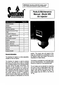
Sentinel™ AIR INJECTOR MODEL 465
IMPORTANT: Read Manual BEFORE installing, operating or maintaining the Sentinel Air Injector Model 465.
Parts & Maintenance Manual - Model 465 Air Injector
| Table of Contents | Page No. |
| General Information | 1 |
| Features | 2 |
| Specifications | 2 |
| Installation Instructions | 2 |
| Operating Instructions & Proper Usage | 3 |
| Information for adjustment | 5 |
| Figure 1 - Model 465 without top cover and filter | 5 |
| Slug Formation Evaluation | 6 |
| Assembly | 6 |
| Figure 2 - Direct mount | 6 |
| Figure 3 - Wall mount | 7 |
| Figure 4 - Electrical hookup Timer | 7 |
| Parts List | 8 |
| Warranty | 8 |
| Contact Information | 8 |
General Information
The Sentinel Air Injector is a time adjustable, variable air flow air injector.
The Sentinel Air Injector is used to produce slug flow in the milk line in order to increase the circulating velocity of the cleaning solution and also reduce the water requirement. The objective of slug formation is to move the cleaning solution throughout the milking system, generate adequate turbulence and provide contact time on all surfaces to perform the proper cleaning function. A solenoid is used to control a piston-type valve that allows periodic injections of atmospheric air into the

system. The proper size and speed of the slugs are controlled by a combination of the Air Injector's Open and Closed Time and its Adjustable Air Intake Sleeve.
The timing is controlled by a solid state timer and two potentiometers. The potentiometers control to a maximum of 30 seconds each.
The air intake can be adjusted by loosening the screw on the air intake sleeve, then rotating the outer sleeve and lining up the indicator mark with the desired air flow. The scale ranges from 20 CFM to 120 CFM at 15" Hg.
With proper slug timing and formation, maximum cleaning efficiency is achieved as bacteria and milk residue are dislodged and flushed out.
The Sentinel Air Injector is different from many other air injectors you may have seen. You may notice that the poppet is loose and it rattles: it is intended to be this way. This is a pilot-operated design. The small solenoid on top opens a small port on top of the free-floating main valve. This controls the vacuum on top of the main valve which is opened and closed by system vacuum. Therefore, the valve must be operated under vacuum to work. This design allows the use of a small solenoid which does not require much current to control a large valve.
The solid-state timer which has no contracts to corrode or burn has two separate controls. The ON knob controls the OPEN TIME or air intake and the OFF knob controls the CLOSED TIME or water pull. Timing can be set from one to 30 seconds in less than one-second increments for both ON-time and OFF-time.
Terminology used in this Manual: To facilitate the reading of this Manual the following terminology will be used. The two timer settings will be referred to as 1) Open Time which is set with the ON-time knob and 2) Closed Time which is set with the OFF-time knob.
Features
- Variable air flow intake markings indicate 20 CFM to 120 CFM. Note: Going to the left of the minimum mark or to the right of the maximum mark will allow approximately 12 CFM to 135 CFM of airflow intake. Removing the air intake cylinder will allow a set maximum air intake flow of approximately 200 CFM. The 20 to 120 CFM scale figures are approximate figures rated at 15" Hg and are deter-
mined with no filter or a clean filter attached.
- Piston-type pilot operated master valve.
- Small solenoid and gravity action for low current consumption.
- Dual ON-time OFF-time controls for alternating air and water slugs.
- Solid state timer for dependable low maintenance service.
- Replaceable filter to keep system free of debris. Filters that fit the Sentinel Air Injector Model 465: Baldwin PA1712, Tecumseh 31925, Fram CA-76 and the WIX 42374.
• One year warranty.
Specifications
• 120 VAC power
- 1 1/2" connecting orifice. Unit connects to system with 1 1/2" ID tubing.
- Air intake capacity 20 to 120 CFM (200 CFM with the air intake cylinder removed).
• Wall or direct mounted.
• Unit requires 5" Hg to activate.
• Shipping weight: 5.5 lbs.
Installation Instructions
- Choose the best location for the Air Injector either above the wash sink or close to the receiver group on the wash supply line. Unit must be mounted at the highest point so water cannot back up into the Sentinel Air Injector.
- Unit can be mounted on the wall or directly to a 1 1/2" nipple, T fitting or elbow.
- Be certain power source is off or plug is disconnected.
-
If the Sentinel Air Injector is to be mounted on the wall remove the two screws from the front of the unit and remove the cover.
-
(Continued from previous page) Mount the unit on the wall using two widely spaced holes. Unit must be mounted vertically with the hose connection pointing down. Suitable ribbed vacuum hose is required between the Air Injector and the inlet into the wash supply line. The hose from the Air Injector to the nipple must be 1 1/2" ID.
- If the Sentinel Air Injector is mounted directly to a 1 1/2 fitting, first butt the two surfaces together. Then use the short piece of tubing and stainless steel band clamps (provided with the Air Injector) to secure the connection. Note: In order to adjust the air intake on the Air Injector there must be enough space below the air filter so that after the filter retaining ring is unscrewed the filter will slide down over the clamps exposing the CFM adjustment on the Adjustable Air Intake Sleeve.
- After installation, replace the cover and the two screws.
- Power source: Suitably grounded 120 VAC outlet. The Sentinel Air Injector is pre-wired with an eight-foot cord ending in a three-prong connector.
Operating Instructions & Proper Usage
There are three variables to consider in order to properly adjust the Sentinel Air Injector:
- OPEN Time. This period of time can be set from 1 to 30 seconds. Nine degrees of turn on the dial equates to 1 second or 45 degrees equates to 5 seconds.
- CLOSED Time. Setting increments same as OPEN Time.
- Amount of air intake through the Air Injector. Air intake can be set from approximately 20 CFM to 120 CFM.
Objectives:
- Air injection is used to produce slug formation in the milk line.
- Air injection increases circulatory velocity of wash solutions and reduces water requirements for cleaning as compared to flooded wash systems.
- Air injection is used to form a slug of cleaning solution and to move this slug around the system to provide adequate turbulence and contact time on all surfaces to perform the cleaning and sanitizing function.
- Formation of a single slug in the milking system occurs because of the cyclic introduction of air and water.
- It is necessary to form one slug and to maintain that slug around the entire pipeline loop to assure all sections are properly cleaned. NOTE: It must be realized that objectives and optimal control strategies for air and water admission into milking units and milk meters differ from those of pipelines alone. Required vacuum pump capacities not only depend upon cyclic air admissions through the Air Injector but also the steady air flow required of all other components during cleaning.
Initial Considerations:
Measure the length of the milk line to be washed and divide it by the average slug velocity of 25 feet per second. This calculation provides a preliminary OPEN Time setting for the Air Injector. Example: 300 feet of line divided by 25 feet per second equals 12 seconds OPEN Time.
Open Time:
- Controls slug movement and washing of the receiver.
(Open Time continued from previous page)
- Allows atmospheric pressure to enter the milk line and initiate slug formation.
- Stops washing water draw from the sink and begins to propel the slug around the milk line to the receiver.
- The rate (CFM) at which air is admitted controls the velocity or speed of the slug being formed.
- Air Injector must remain open until the slug approaches the receiver.
- Once volume of slug is established, the Air Injector should be closed just prior to slug entry into the receiver.
Closed Time:
- Closing the Air Injector initiates slug formation and allows the solution to be drawn or pumped from the wash vat to the pipeline.
- The amount of cleaning solution (slug size and volume) drawn into the system is controlled by the air injection CLOSED Time.
- The slug volume and size should be such that the receiver is not filled above the milk inlet lines. Preferably the receiver should not be filled over 1/3 full.
- CLOSED Time should be initiated just prior to the slug entering the receiver and remain closed (OFF) until the milk pump is able to clear the receiver. A very large slug will flood the receiver and hinder movement of cleaning solution in the receiver.
- CLOSED Time should be increased until the slug reaches the receiver with enough volume to thoroughly wash all the receiver surfaces, but not flood over into the sanitary trap.
- The slug length is formed immediately upon the opening of the Air Injector.
System setup for cleaning:
- Set up system for actual washing with hot water and detergent in sink. Turn on the vacuum pump.
- Remove the cover of the Air Injector to reveal the timer control knobs. Set the OPEN Time as previously determined in Initial Considerations and CLOSED Time to 10 seconds. See Information for Adjustment (page 5).
CAUTION:
There is no ON/OFF switch for the Sentinel Air Injector. When attached to the system and connected to the electrical power the Air Injector may turn on at any time. When adjusting the "ON" or "OFF" knobs, DO NOT TOUCH any other components of the Air Injector.
- Unscrew the filter retaining ring and lower the Air Filter to reveal the Adjustable Air Intake Sleeve. Set the Adjustable Air Intake Sleeve (Figure 1, page 5) according to the table in Information for Adjustment (page 5). Loosen the set-screw on the Air Intake Sleeve then rotate the outer sleeve in order to line up the indicator mark with the desired air flow. Then, tighten the set-screw.
- Make refinements to OPEN/CLOSED Times and air intake by observing receiver coverage and monitoring the slug formation and movement. Review the previous section titled Initial Considerations.
Assumptions:
- Milk lines are properly sloped. Generally first half upwards and second half downwards.
- Proper chemicals and cycles are established.
- Milk pump discharge is capable of keeping up with the system intake. If the system can draw solution out of the wash sink faster than the pump can discharge it, the system will not clean without flooding the trap and losing cleaning solution.
Information for Adjustment
- Air injection timing ranges depend upon milk line size and length:
• Average OPEN Time ranges from 5 to 15 seconds. - Average CLOSED Time ranges from 15 to 30 seconds.

Figure 1 - Sentinel Air Injector Model 465 without top cover and filter.
- Ratio of air injection, OPEN to CLOSED Time, typically 50% or less for cycled air injection.
- Increasing air flows above maximum rates will not improve cleaning action in the milk line. Optimum slug velocity for proper cleaning is approximately 20 to 33 feet per second. Fifteen to twenty correct slugs (size and velocity) will properly clean the milk line. Additional air merely allows line to cool below dumping temperature requirements.
- Suggested range of air flows required to form and maintain a slug and average slug velocity for a single looped line are:
| Line Size inches | Air Flow scfm | Avg. Vel. Ft./sec. |
| 2.0 | 12-25 | 20-33 |
| 2.5 | 18-39 | 20-33 |
| 3.0 | 27-58 | 20-33 |
| 4.0 | 48-104 | 20-33 |
- Increasing the air admission above the maximum suggested limits will result in reduced slug density and reduced mechanical cleaning.
Precautions:
- High velocities require the Air Injector to be closed for a long time prior to the slug entering the receiver to allow the pressure to drop and to slow the slug speed.
-
Excessive air admission will increase the slip coefficient (ratio of air to water) and also increase the amount of air entrained in the slug. Increased air reduces shear stress and acts to break down the slug.
-
Some milk/wash valves may short circuit a significant volume of injected air directly to the receiver. This valve may have to be refitted to closer tolerances. This malfunction could reduce pressure following the slug and simultaneously reduce the vacuum in front of the slug thereby reducing the pressure difference and slowing the slug velocity.
- If air admission during the air injection phase exceeds the vacuum pump capacity, the system vacuum will fall. The system must recover during the closed phase for proper slug movement.
Slug Formation Evaluation
A single test point can be used to determine the slug presence but a two-channel recording provides an advantage to easily determine the slug velocity and length. The presence of a rapid vacuum drop when the slug passes a specific point indicates slug formation. It is possible to use two vacuum

Figure 2 - Air Injector connected directly to washline "T" i.e. Direct mount.
measuring devices and to observe a vacuum drop as the slug passes the two specific points within the milking system. Measure the time and distance between the points to determine the velocity.
Facts to Consider:
- Vacuum drop as slug passes a specific point indicates slug.
- Time for slug to pass two specific points indicates velocity.
- Degree of vacuum drop represents measurement of cleaning.
- Vacuum drop decreases as slug travels cleaning circuit.
- Magnitude of drop is dependent on line size and the travel distance.
- Vacuum differential caused by slug is greatest at beginning of cycle.
- Inadequate or slowly varying vacuum drop often indicates slow or short slug and/or that excessive air is passing through slug.
- Slug length can be increased by increasing Air Injector CLOSED Time and drawing more water per cycle into system.
Assembly
Important: Before any disassembly/assembly is done on the Air Injector, be sure to disconnect the unit from its power source.
The Mounting Bracket Assembly (part# 465-41) is the part in the Air Injector that has the Timer, Solenoid Assembly and the 2 Potentiometers attached to it. Two screws attach this part to the Base (part# 465-2). If the Mounting Bracket Assembly is removed from the Base, for example to replace a potentiometer, make sure that when the Mounting Bracket Assembly is assembled onto the Base, that the Mounting Bracket Assembly is positioned so that
Assembly (continued)
the two arms of the Solenoid do not hit the part of the Housing which extends up through a hole in the Base. The part of the Housing which extends up through a hole in the Base should be centered between the two arms of the Solenoid before the Mounting Bracket Assembly is secured to the Base.

Figure 3 - Air Injector mounted to wall and connected to washline with ribbed tubing.

Figure 4 - Electrical hookup for Timer.
Bibliography: Sources used in this Manual's preparation:
- MILKLINE CLEANING DYNAMICS: DESIGN GUIDELINES AND TROUBLESHOOTING, Douglas J. Reinemann and Albrecht Grasshoff, Agricultural Engineering Department, Univ. of WI - Madison, Federal Center for Dairy Research, Kiel, Germany, from NMC Annual Meeting Proceedings, 1993.
- AIRFLOW REQUIREMENTS, DESIGN PARAMETERS AND TROUBLE-SHOOTING FOR CLEANING MILKING SYSTEMS, D. J. Reinemann and J. M. Book, University of WI, Madison, WI, Babson Bros. Co. Naperville, IL, from NMC Annual Meeting Proceedings, January 31-February 2, 1994.
- SIZING VACCUM PUMPS FOR CLEANING MILKING SYSTEMS, Douglas J. Reinemann and Graeme A. Mein, Univ. of WI, Madison, WI, from NMC Annual Meeting Proceedings, Feb. 20-22, 1995.
Sentinel Air Injector Model 465 Parts List
| PART NUMBER | DESCRIPTION |
| AI-465 | Complete Unit |
| 387-3 | Inlet Ring |
| 387-5 | Piston |
| 387-29 | Timer |
| 462-6-100 | Filter retaining ring |
| 465-2 | Base |
| 465-4 | Piston Housing |
| 465-8 | Adjustable Air Intake Sleeve - ported sleeve |
| 465-10 | Outer Cover |
| 465-27A | Potentiometer Assembly |
| PART NUMBER | DESCRIPTION |
| 465-37 | Electrical Cover |
| 00832025SPNSL | Electrical Cover screw |
| 00832025SPNSL | Adj. Air Intake screw |
| 008SWRCRS | Adj. Air Intake lock washer |
| 465-41 | Mounting Bracket Assembly |
| 465-50 | Solenoid Assembly |
| 465-52 | Plunger |
| 00832062SPNSL | Outer Cover screws |
- LIMITED WARRANTY: Seller warrants that the goods delivered shall be free from defects in material and workmanship for a period of one (1) year from the date of Seller's shipment. Seller's sole obligation and Buyer's exclusive remedy for defects in the goods shall be limited, at Seller's option, to either repair or replacement of goods determined to be defective. Transportation and any other delivery costs to return defective goods to Seller for repair or replacement shall be the responsibility of Buyer. Any claim by Buyer must be made by Buyer to Seller in writing within five (5) days of the discovery of the claimed defect but in no event after the expiration of one (1) year from the date of Sellers's shipment, whichever is less. Buyer's failure to so notify Seller of such defects within the above time periods shall bar Buyer from any remedy under this Warranty, or for recovery of damages or losses due to defects in the goods. Any return of goods shall be subject to the prior written approval of Seller.
THIS WARRANTY IS THE SOLE WARRANTY COVERING THE GOODS AND SELLER MAKES NO OTHER WARRANTY OF ANY KIND, WHETHER EXPRESS, IMPLIED OR STATUTORY, AND ALL IMPLIED WARRANTIES OF MERCHANTABILITY AND FITNESS FOR A PARTICULAR PURPOSE ARE HEREBY DISCLAIMED BY SELLER AND EXCLUDED FROM THIS WARRANTY. IN NO EVENT SHALL SELLER BE LIABLE FOR CONSEQUENTIAL, COMPENSATORY, PUNITIVE OR INCIDENTAL DAMAGES HOWSOEVER ARISING FROM SELLER'S PERFORMANCE OF THIS CONTRACT OR THE PERFORMANCE OF THE GOODS.
This Warranty shall not apply to goods which have been repaired or altered by other than authorized representatives of Seller or to damage or defects caused by accident, vandalism, Acts of God, erosion, normal wear and tear, improper selection by Buyer or others, and other causes beyond Seller's control. This Warranty shall not apply to the misapplication, improper installation, or misuse of the goods caused by variations in environment, the inappropriate extrapolation of data provided, the failure of Buyer or others to adhere to pertinent specifications or industry practices, or otherwise.
- LIMITATION OF SELLER'S LIABILITY: Seller's liability on any claim of any kind, including claims based upon Seller's negligence, breach of contract, or strict liability in tort, for any loss or damage arising out of, connected with, or resulting from the use of the goods furnished hereunder or Seller's performance of this contract, shall in no case exceed the purchase price allocable to the goods or part thereof which give rise to the claim. IN NO EVENT SHALL SELLER BE LIABLE FOR SPECIAL, INCIDENTAL, OR CONSEQUENTIAL DAMAGES HOWSOEVER ARISING OUT OF SELLER'S PERFORMANCE OF THIS CONTRACT AND NOTWITHSTANDING WHETHER SELLER MAY HAVE BEEN ADVISED OR IS ADVISED OF THE POSSIBILITY OF SPECIAL (OR LIQUIDATED) DAMAGES.

L. J. ENGINEERING, INC.
18192 Gothard Street, Huntington Beach, CA 92648 USA
Phone: (714) 848-8001• In USA: 800-635-6413
Fax: (714) 848-0973 Email: info@ljengineering.com
www.sentinelproducts.com
- SENTINEL™ AIR INJECTOR MODEL
- PARTS & MAINTENANCE MANUAL - MODEL 465 AIR INJECTOR
- GENERAL INFORMATION
- FEATURES
- SPECIFICATIONS
- INSTALLATION INSTRUCTIONS
- OPERATING INSTRUCTIONS & PROPER USAGE
- OBJECTIVES
- INITIAL CONSIDERATIONS
- OPEN TIME
- CLOSED TIME
- SYSTEM SETUP FOR CLEANING
- CAUTION
- ASSUMPTIONS
- INFORMATION FOR ADJUSTMENT
- PRECAUTIONS
- SLUG FORMATION EVALUATION
- FACTS TO CONSIDER
- ASSEMBLY
- ASSEMBLY (CONTINUED)
- ENGINEERING, INC
Marque : Coburn
Modèle : M465
Catégorie : Injecteur d'air