
C200HW-SRM21-V1 - Automatisme industriel OMRON - Notice d'utilisation et mode d'emploi gratuit
Retrouvez gratuitement la notice de l'appareil C200HW-SRM21-V1 OMRON au format PDF.


| Type de produit | Unité maître CompoBus/S |
| Marque | OMRON |
| Modèle | C200HW-SRM21-V1 |
| Catégorie | Automatisme industriel |
| Compatibilité automates | CS-series, C200HX/C200HG/C200HE-(Z)E, C200HS |
| Nombre maximal d'esclaves | 32 |
| Nombre maximal de points I/O | 256 (128 entrées / 128 sorties) ou 128 (64/64) selon réglage |
| Modes de communication | Haute vitesse (750 kbps) ou Longue distance (93.75 kbps) |
| Cycle de communication | Haute vitesse : 0,5 ms ou 0,8 ms ; Longue distance : 4,0 ms ou 6,0 ms |
| Alimentation | Alimenté par l'automate (PLC) |
| Câbles compatibles | VCTF 2 ou 4 conducteurs, câble plat spécial |
| Distance maximale (mode haute vitesse) | 100 m (câble 2 conducteurs) / 30 m (câble 4 conducteurs) |
| Distance maximale (mode longue distance) | 500 m (câble 2 conducteurs) / 200 m (câble 4 conducteurs) |
| Méthodes de raccordement | Dérivation en T, multidrop |
| Indicateurs | LEDs d'état |
| Fonctions de diagnostic | Enregistrement des esclaves, arrêt des communications sur erreur |
| Mise à la terre | Nécessaire (résistance ≤ 100 Ω) |
| Sécurité | Couper l'alimentation avant toute manipulation |
| Entretien | Inspection régulière, nettoyage |
FOIRE AUX QUESTIONS - C200HW-SRM21-V1 OMRON
Questions des utilisateurs sur C200HW-SRM21-V1 OMRON
0 question sur cet appareil. Repondez a celles que vous connaissez ou posez la votre.
Poser une nouvelle question sur cet appareil
Téléchargez la notice de votre Automatisme industriel au format PDF gratuitement ! Retrouvez votre notice C200HW-SRM21-V1 - OMRON et reprennez votre appareil électronique en main. Sur cette page sont publiés tous les documents nécessaires à l'utilisation de votre appareil C200HW-SRM21-V1 de la marque OMRON.
MODE D'EMPLOI C200HW-SRM21-V1 OMRON
C200HW-SRM21-V1
CS1W-SRM21
CJ1W-SRM21
CQM1-SRM21-V1
SRT1 Series
SRT2 Series
CompoBus/S
OPERATION MANUAL
C200HW-SRM21-V1
CS1W-SRM21
CJ1W-SRM21
CQM1-SRM21-V1
SRT1 Series
SRT2 Series
CompoBus/S
Operation Manual
Revised August 2007
Notice:
OMRON products are manufactured for use according to proper procedures by a qualified operator and only for the purposes described in this manual.
The following conventions are used to indicate and classify precautions in this manual. Always heed the information provided with them. Failure to heed precautions can result in injury to people or damage to property.

Indicates an imminently hazardous situation which, if not avoided, will result in death or serious injury. Additionally, there may be severe property damage.

Indicates a potentially hazardous situation which, if not avoided, could result in death or serious injury. Additionally, there may be severe property damage.

Indicates a potentially hazardous situation which, if not avoided, may result in minor or moderate injury, or property damage.
OMRON Product References
All OMRON products are capitalized in this manual. The word "Unit" is also capitalized when it refers to an OMRON product, regardless of whether or not it appears in the proper name of the product.
The abbreviation "Ch," which appears in some displays and on some OMRON products, often means "word" and is abbreviated "Wd" in documentation in this sense.
The abbreviation "PLC" means Programmable Controller and is not used as an abbreviation for anything else.
Visual Aids
The following headings appear in the left column of the manual to help you locate different types of information.
Note Indicates information of particular interest for efficient and convenient operation of the product.
1,2,3... 1. Indicates lists of one sort or another, such as procedures, checklists, etc.
OMRON, 1996
All rights reserved. No part of this publication may be reproduced, stored in a retrieval system, or transmitted, in any form, or by any means, mechanical, electronic, photocopying, recording, or otherwise, without the prior written permission of OMRON.
No patent liability is assumed with respect to the use of the information contained herein. Moreover, because OMRON is constantly striving to improve its high-quality products, the information contained in this manual is subject to change without notice. Every precaution has been taken in the preparation of this manual. Nevertheless, OMRON assumes no responsibility for errors or omissions. Neither is any liability assumed for damages resulting from the use of the information contained in this publication.
TABLE OF CONTENTS
PRECAUTIONS XV
1 Intended Audience xvi
2 General Precautions xvi
3 Safety Precautions. xvi
4 Operating Environment Precautions xvii
5 Application Precautions xviii
6 Conformance to EC Directives. xxi
SECTION 1 System Design 1
1-1 System Overview and Features 2
1-2 CompoBus/S System Configuration 6
1-3 Compatible Devices 10
1-4 Startup Procedure 20
SECTION 2 CompoBus/S System Specifications and Configuration 23
2-1 Communications Specifications 24
2-2 System Configuration 25
2-3 Supplying Power to the Slaves 31
2-4 System Configuration Using Water-resistant Terminals 41
2-5 I/O Response Time Characteristics 41
SECTION 3 CompoBus/S System Wiring 53
3-1 Mounting. 54
3-2 Connector Installation (Special Flat Cable Only) 55
3-3 VCTF Cable Assembly. 64
3-4 Master/Slave Connecting Cables 66
3-5 Operations Checklist. 70
SECTION 4 Master Unit Specifications and Operations 73
4-1 C200HW-SRM21-V1 Master Unit for CS-series, C200HX/C200HG/C200HE-(Z)E, and C200HS PLCs 74
4-2 CS1W-SRM21 Master Unit for CS-series PLCs 88
4-3 CJ1W-SRM21 Master Unit for CJ-series PLCs 104
4-4 CQM1-SRM21-V1 Master Unit for CQM1 PLCs 126
4-5 SRM1-C0□-V2 Master Control Units 136
4-6 CPM2C-S Series CPM2C-S□□□C (-DRT). 140
TABLE OF CONTENTS
SECTION 5
Slave Specifications and Operations 145
5-1 Remote Terminals 147
5-2 Connector Terminals 194
5-3 Remote I/O Modules 260
5-4 Water-resistant Terminals 268
5-5 Sensor Terminals 287
5-6 Fiber Amplifier Communications Units 301
5-7 Analog Input Terminals 308
5-8 Analog Output Terminals 318
5-9 I/O Link Units for CPM1A and CPM2A. 327
5-10 I/O Link Units for CPM2C 331
5-11 Sensor Amplifier Terminals 335
5-12 Application Precautions. 350
SECTION 6
Starting Communications. 353
6-1 Turning the Power ON. 354
6-2 Checking Operations for CS-series, C200HX/C200HG/C200HE-(Z)E, and C200HS Master Units 356
6-3 Checking Operations of CS-series and CJ-series Master Units. 365
6-4 Checking Operations of CQM1 Master Units 377
6-5 Checking Slave Operations 382
6-6 Cleaning and Inspection 384
6-7 Precautions for Replacement of Units or Parts 385
Appendix
Standard Models 387
Index. 395
Revision History 401
About this Manual:
This manual describes the installation and operation of the CompoBus/S system and includes the sections described below.
Please read this manual carefully and be sure you understand the information provided before attempting to install and operate the CompoBus/S Master and Slave Units. Be sure to read the precautions provided in the following section.
Section 1 provides an overview of the CompoBus/S System and functions, and describes the various Units that are used to configure a CompoBus/S System.
Section 2 provides details on the CompoBus/S System specifications and I/O response times, and explains how to configure a CompoBus/S System.
Section 3 explains how to install Units in control panels, wire the signal and power lines, and make other connections needed to assemble a CompoBus/S System. We recommend reading through the information on wiring each Master and Slave that are provided in Section 4 and Section 5.
Section 4 explains the functions of each Master Unit, including information on specifications, switch settings and allocation of Slave I/O.
Section 5 explains the functions of each Slave, including information on specifications, switch settings, and I/O.
Section 6 provides information on error processing, periodic maintenance operations, and troubleshooting procedures needed to keep the CompoBus/S System operating properly. We recommend reading through the error processing procedures before operation so that operating errors can be identified and corrected more quickly.
The Appendix provides tables of standard models including Masters, Slaves, and connecting devices. In this manual, only the specifications of the CompoBus/S system and devices are described. For details on Units, refer to their respective manuals. (Suffixes have been omitted from the catalog numbers.)
| Product Name | Series | Manual Name | Cat. No. |
| CS-series Programmable Controllers | CS Series | SYSMAC CS Series Operation Manual | W339 |
| CJ-series Programmable Controllers | CJ Series | SYSMAC CJ Series Operation Manual | W393 |
| CS/CJ-series Programmable Control- lers | CS/CJ Series | SYSMAC CS/CJ Series Pro- gramming Manual | W394 |
| C200HX/C200HG/C200HE-(Z)E Pro- grammatical Controllers | C200HX/C200HG/ C200HE-(Z)E | SYSMAC C200HX/C200HG/ C200HE-(Z)E Programmable Controllers Installation Guide | W302 |
| C200HX/C200HG/C200HE-(Z)E Pro- grammatical Controllers | C200HX/C200HG/ C200HE-(Z)E | SYSMAC C200HX/C200HG/ C200HE-(Z)E Programmable Controllers Operation Manual | W322 |
| C200HS Programmable Controllers | C200HS | SYSMAC C200HS Operation Manual | W235 |
| C200HS Programmable Controllers | C200HS | SYSMAC C200HS Installation Guide | W236 |
| CQM1H Programmable Controller | CQM1H | SYSMAC CQM1H Operation Manual | W363 |
| CQM1H Programmable Controller | CQM1H | SYSMAC CQM1H Programming Manual | W364 |
| CQM1 Programmable Controller | CQM1 | SYSMAC CQM1 Operation Man- ual | W226 |
| CQM1/CPM1/CPM1A/SRM1 Pro-grammable Controller | CQM1/CPM1/CPM1A/SRM1 | SYSMAC CQM1/CPM1/CPM1A/SRM1 Programming Manual | W228 |
| CompoBus/S SRM1 Master Control Unit | SRM1(-V2) | SYSMAC CompoBus/S SRM1Master Control Units Operation Manual | W318 |
| CPM2C-S Programmable Controller | CPM2C-S | SYSMAC CPM2C-S Programma-ble Controllers Operation Manual | W377 |
| CPM1A/CPM2A I/O Link Unit | CPM1A-SRT21 | SYSMAC CPM2A I/O Link UnitsOperation Manual | W352 |
| CPM2C I/O Link Unit | CPM2C-SRT21 | SYSMAC CPM2C I/O Link UnitsOperation Manual | W356 |

Failure to read and understand the information provided in this manual may result in personal injury or death, damage to the product, or product failure. Please read each section in its entirety and be sure you understand the information provided in the section and related sections before attempting any of the procedures or operations given.
Read and Understand this Manual
Please read and understand this manual before using the product. Please consult your OMRON representative if you have any questions or comments.
Warranty and Limitations of Liability
WARRANTY
OMRON's exclusive warranty is that the products are free from defects in materials and workmanship for a period of one year (or other period if specified) from date of sale by OMRON.
OMRON MAKES NO WARRANTY OR REPRESENTATION, EXPRESS OR IMPLIED, REGARDING NONINFRINGEMENT, MERCHANTABILITY, OR FITNESS FOR PARTICULAR PURPOSE OF THE PRODUCTS. ANY BUYER OR USER ACKNOWLEDGES THAT THE BUYER OR USER ALONE HAS DETERMINED THAT THE PRODUCTS WILL SUITABLY MEET THE REQUIREMENTS OF THEIR INTENDED USE. OMRON DISCLAIMS ALL OTHER WARRANTYES, EXPRESS OR IMPLIED.
LIMITATIONS OF LIABILITY
OMRON SHALL NOT BE RESPONSIBLE FOR SPECIAL, INDIRECT, OR CONSEQUENTIAL DAMAGES, LOSS OF PROFITS OR COMMERCIAL LOSS IN ANY WAY CONNECTED WITH THE PRODUCTS, WHETHER SUCH CLAIM IS BASED ON CONTRACT, WARRANTY, NEGLIGENCE, OR STRICT LIABILITY.
In no event shall the responsibility of OMRON for any act exceed the individual price of the product on which liability is asserted.
IN NO EVENT SHALL OMRON BE RESPONSIBLE FOR WARRANTY, REPAIR, OR OTHER CLAIMS REGARDING THE PRODUCTS UNLESS OMRON'S ANALYSIS CONFIRMS THAT THE PRODUCTS WERE PROPERLY HANDLED, STORED, INSTALLED, AND MAINTAINED AND NOT SUBJECT TO CONTAMINATION, ABUSE, MISUSE, OR INAPPROPRIATE MODIFICATION OR REPAIR.
Application Considerations
| SUITABILITY FOR USE |
| OMRON shall not be responsible for conformity with any standards, codes, or regulations that apply to the combination of products in the customer's application or use of the products. |
| At the customer's request, OMRON will provide applicable third party certification documents identifying ratings and limitations of use that apply to the products. This information by itself is not sufficient for a complete determination of the suitability of the products in combination with the end product, machine, system, or other application or use. |
| The following are some examples of applications for which particular attention must be given. This is not intended to be an exhaustive list of all possible uses of the products, nor is it intended to imply that the uses listed may be suitable for the products:· Outdoor use, uses involving potential chemical contamination or electrical interference, or conditions or uses not described in this manual.· Nuclear energy control systems, combustion systems, railroad systems, aviation systems, medical equipment, amusement machines, vehicles, safety equipment, and installations subject to separate industry or government regulations.· Systems, machines, and equipment that could present a risk to life or property.Please know and observe all prohibitions of use applicable to the products.NEVER USE THE PRODUCTS FOR AN APPLICATION INVOLVING SERIOUS RISK TO LIFE OR PROPERTY WITHOUT ENSURING THAT THE SYSTEM AS A WHOLE HAS BEEN DESIGNED TO ADDRESS THE RISKS, AND THAT THE OMRON PRODUCTS ARE PROPERLY RATED AND INSTALLED FOR THE INTENDED USE WITHIN THE OVERALL EQUIPMENT OR SYSTEM. |
| PROGRAMMABLE PRODUCTS |
| OMRON shall not be responsible for the user's programming of a programmable product, or any consequence thereof. |
Disclaimers
| CHANGE IN SPECIFICATIONS |
| Product specifications and accessories may be changed at any time based on improvements and other reasons.It is our practice to change model numbers when published ratings or features are changed, or when significant construction changes are made. However, some specifications of the products may be changed without any notice. When in doubt, special model numbers may be assigned to fix or establish key specifications for your application on your request. Please consult with your OMRON representative at any time to confirm actual specifications of purchased products. |
| DIMENSIONS AND WEIGHTS |
| Dimensions and weights are nominal and are not to be used for manufacturing purposes, even when tolerances are shown. |
| PERFORMANCE DATA |
| Performance data given in this manual is provided as a guide for the user in determining suitability and does not constitute a warranty. It may represent the result of OMRON's test conditions, and the users must correlate it to actual application requirements. Actual performance is subject to the OMRON Warranty and Limitations of Liability. |
| ERRORS AND OMISSIONS |
| The information in this manual has been carefully checked and is believed to be accurate; however, no responsibility is assumed for clerical, typographical, or proofreading errors, or omissions. |
This section provides general precautions for using the CompoBus/S Units, Programmable Controllers, and related devices. The information contained in this section is important for the safe and reliable application of the CompoBus/S and PLC. You must read this section and understand the information contained before attempting to set up or operate a CompoBus/S and PLC system.
1 Intended Audience xvi
2 General Precautions xvi
3 Safety Precautions. xvi
4 Operating Environment Precautions xvii
5 Application Precautions xviii
6 Conformance to EC Directives xxi
6-1 Applicable Directives xxi
6-2 Concepts xxi
6-3 Conformance to EC Directives. xxi
1 Intended Audience
This manual is intended for the following personnel, who must also have knowledge of electrical systems (an electrical engineer or the equivalent).
- Personnel in charge of installing FA systems.
- Personnel in charge of designing FA systems.
- Personnel in charge of managing FA systems and facilities.
2 General Precautions
The user must operate the product according to the performance specifications described in the operation manuals.
Before using the product under conditions which are not described in the manual or applying the product to nuclear control systems, railroad systems, aviation systems, vehicles, combustion systems, medical equipment, amusement machines, safety equipment, and other systems, machines, and equipment that may have a serious influence on lives and property if used improperly, consult your OMRON representative.
Make sure that the ratings and performance characteristics of the product are sufficient for the systems, machines, and equipment, and be sure to provide the systems, machines, and equipment with double safety mechanisms.
This manual provides information for installing and operating OMRON CompoBus/S Units. Be sure to read this manual before operation and keep this manual close at hand for reference during operation.
WARNING
It is extremely important that a PLC and all PLC Units be used for the specified purpose and under the specified conditions, especially in applications that can directly or indirectly affect human life. You must consult with your OMRON representative before applying a PLC System to the above-mentioned applications.
3 Safety Precautions
WARNING Do not attempt to take any Unit apart while the power is being supplied. Doing so may result in electric shock.
WARNING Do not touch any of the terminals or terminal blocks while the power is being supplied. Doing so may result in electric shock.
WARNING Provide safety measures in external circuits, i.e., not in the Programmable Controller (CPU Unit including associated Units; referred to as "PLC"), in order to ensure safety in the system if an abnormality occurs due to malfunction of the PLC or another external factor affecting the PLC operation. Not doing so may result in serious accidents.
- Emergency stop circuits, interlock circuits, limit circuits, and similar safety measures must be provided in external control circuits.
-
The PLC will turn OFF all outputs when its self-diagnosis function detects any error or when a severe failure alarm (FALS) instruction is executed. As a countermeasure for such errors, external safety measures must be provided to ensure safety in the system.
-
The PLC outputs may remain ON or OFF due to deposition or burning of the output relays or destruction of the output transistors. As a countermeasure for such problems, external safety measures must be provided to ensure safety in the system.
- When the 24-VDC output (service power supply to the PLC) is overloaded or short-circuited, the voltage may drop and result in the outputs being turned OFF. As a countermeasure for such problems, external safety measures must be provided to ensure safety in the system.
WARNING Do not attempt to disassemble, repair, or modify any Units. Any attempt to do so may result in malfunction, fire, or electric shock.
Caution Execute online edit only after confirming that no adverse effects will be caused by extending the cycle time. Otherwise, the input signals may not be readable.
Caution Confirm safety at the destination node before transferring a program to another node or editing the I/O area. Doing either of these without confirming safety may result in injury.
Caution Tighten the screws on the terminal block of the AC Power Supply Unit to the torque specified in the operation manual. The loose screws may result in burning or malfunction.
4 Operating Environment Precautions
Caution Do not operate the control system in the following places:
- Locations subject to direct sunlight
- Locations subject to temperatures or humidity outside the range specified in the specifications
- Locations subject to condensation as the result of severe changes in temperature
- Locations subject to corrosive or flammable gases
- Locations subject to dust (especially iron dust) or salts
- Locations subject to exposure to water, oil, or chemicals
- Locations subject to shock or vibration
Caution Take appropriate and sufficient countermeasures when installing systems in the following locations:
- Locations subject to static electricity or other forms of noise
- Locations subject to strong electromagnetic fields
- Locations subject to possible exposure to radioactivity
- Locations close to power supplies
Caution
The operating environment of the PLC System can have a large effect on the longevity and reliability of the system. Improper operating environments can lead to malfunction, failure, and other unforeseeable problems with the PLC System. Be sure that the operating environment is within the specified conditions at installation and remains within the specified conditions during the life of the system.
5 Application Precautions
Observe the following precautions when using the CompoBus/S Units or the PLC.
WARNING
Failure to abide by the following precautions could lead to serious or possibly fatal injury. Always heed these precautions.
- Always connect to 100 or less when installing the Units. Not connecting to a ground of 100 or less may result in electric shock.
-
Always turn OFF the power supplies to the PLC, slaves, and communications before attempting any of the following. Not turning OFF the power supplies may result in malfunction or electric shock.
-
Mounting or dismounting Power Supply Units, I/O Units, CPU Units, memory cassettes, Master Units, or any other Units
- Mounting or dismounting circuits for Remote I/O Terminals with 3-tier terminal blocks
- Assembling the Units or Racks
- Setting DIP switches or rotary switches
- Connecting or wiring the cables
- Connecting or disconnecting the connectors
Caution
Failure to abide by the following precautions could lead to faulty operation or the PLC or the system or could damage the PLC or PLC Units. Always heed these precautions.
- Failsafe measures must be taken by the customer to ensure safety in the event of incorrect, missing, or abnormal signals caused by broken signal lines, momentary power interruptions, or other causes.
- Provide external interlock circuits, limit circuits, and other safety circuits in addition to any provided within the PLC to ensure safety.
- Configure the control circuits to turn ON the power supply to I/O slaves before turning ON the power supply to the PLC (Master Unit). If the I/O slave power supply is turned ON after the PLC, correct operation may temporarily not be possible.
- Do not attempt to disassemble, repair, or modify any Units. Any attempt to do so may result in malfunction, fire, or electric shock.
- Do not drop the Unit or subject it to excessive vibration or shock.
- Be sure that all the Backplane mounting screws, slave mounting screws, terminal screws, and cable connector screws are tightened to the torque specified in the relevant manuals. Incorrect tightening torque may result in malfunction.
-
Wire correctly according to specified procedures.
-
Pay careful attention to the polarity (+/-) when connecting the terminal blocks or connectors. Wrong connections may cause malfunction of the system.
- Wire all terminals, communications paths, power supplies lines, and I/O lines with the specified polarity and voltages. Improper wiring may result in faulty operation.
- Install external breakers and take other safety measures against short-circuiting in external wiring. Insufficient safety measures against short-circuiting may result in burning.
- Do not mount the Unit near equipment that generates strong high-frequency noise.
- Leave the label attached to the Unit when wiring to prevent wire clippings and other foreign matter from entering the Unit. Removing the label may result in malfunction.
- Remove the label after the completion of wiring to ensure proper heat dissipation. Leaving the label attached may result in malfunction.
- Use crimp terminals for wiring. Do not connect bare stranded wires directly to terminals. Connection of bare stranded wires may result in burning.
- Wire correctly and double-check all the wiring or the setting switches before turning ON the power supply. Incorrect wiring may result in burning.
- Be sure that the terminal blocks, connectors, expansion cables, and other items with locking devices are properly locked into place. Improper locking may result in malfunction.
- Disconnect the LG and GR terminals on the Power Supply Unit before performing insulation resistance or dielectric strength tests.
- Always use the power supply voltage specified in the operation manual. An incorrect voltage may result in malfunction or burning.
- Take appropriate measures to ensure that the specified power with the rated voltage and frequency is supplied. Be particularly careful in places where the power supply is unstable. An incorrect power supply may result in malfunction.
- Do not apply voltages to the Input Units in excess of the rated input voltage. Excess voltages may result in burning.
- Do not apply voltages exceeding the maximum switching capacity to Output Units. The Output Units may be destroyed.
- Check the user program for proper execution before actually running it on the Unit. Not checking the program may result in an unexpected operation.
-
Always turn OFF the power supplies to the PLC, slaves, and communications before attempting any of the following. Not turning OFF the power supply may result in malfunction or electric shock.
-
Mounting or dismounting Power Supply Units, I/O Units, CPU Units, memory cassettes Master Unit, or any other Units
- Mounting or dismounting circuits for Remote I/O Terminals with 3-tier terminal blocks.
- Assembling the Units
- Setting DIP switches or rotary switches
-
Connecting or wiring the cables
-
Connecting or disconnecting the connectors
-
Before touching the Unit, be sure to first touch a grounded metallic object in order to discharge any static built-up. Not doing so may result in malfunction or damage.
-
Confirm that no adverse effect will occur in the system before attempting any of the following. Not doing so may result in an unexpected operation.
-
Changing the operating mode of the PLC. (including the Startup Mode setting)
- Force-setting/force-resetting any bit in memory.
-
Changing the present value of any word or any set value in memory.
-
When replacing parts, be sure to confirm that the rating of a new part is correct. Not doing so may result in malfunction or burning.
- Resume operation only after transferring to the new CPU Unit and/or Special I/O Units the contents of the DM and HR Areas required for resuming operation. Not doing so may result in an unexpected operation.
- When transporting the Units, use special packing boxes and protect them from excessive vibration or shock during transportation.
- Connect all communications cables within the limits given in the specifications.
-
Observe the following precautions when wiring communications cables.
-
Separate the communications cables from power lines or high-tension lines.
- Do not bend the communications cables.
- Do not pull on the communications cables with an excessive force.
- Do not place heavy objects on the communications cables.
-
Be sure to put the communications cables inside conduits.
-
Water-resistant Terminals used as Slaves are of IP67 construction. Do not attempt to use the Watertight Terminals for applications where the Watertight Terminals are always underwater.
- Install the Unit properly as specified in the operation manual. Improper installation of the Unit may result in malfunction.
6 Conformance to EC Directives
6-1 Applicable Directives
EMC Directives
6-2 Concepts
EMC Directives
OMRON devices that comply with EC Directives also conform to the related EMC standards so that they can be more easily built into other devices or the overall machine. The actual products have been checked for conformity to EMC standards (see the following note). Whether the products conform to the standards in the system used by the customer, however, must be checked by the customer.
EMC-related performance of the OMRON devices that comply with EC Directives will vary depending on the configuration, wiring, and other conditions of the equipment or control panel on which the OMRON devices are installed. The customer must, therefore, perform the final check to confirm that devices and the overall machine conform to EMC standards.
Note Applicable EMC (Electromagnetic Compatibility) standards are listed in the following table.
| Unit | EMS (Electromagnetic Susceptibility) | EMI (Electromagnetic Interference) |
| C200HW-SRM21-V1 | EN61131-2 | EN61000-6-4 (See note 2.) |
| CS1W-SRM21 | EN61131-2 | |
| CJ1W-SRM21 | EN61000-6-2 (See note 1.) | |
| CQM1-SRM21-V1 | EN61131-2 | |
| SRM1-C0□-V2 | EN61000-6-2 (See note 1.) | |
| CPM2C-S□□□C(-DRT) | EN61131-2 | |
| SRT1 and SRT2 Series | EN61000-6-2 (See note 1.) |
Note 1. These products have configurations with less than 30m of I/O wiring, and less than 10m of power supply wiring.
- Radiated emission for EN61000-6-4: 10-m regulations
6-3 Conformance to EC Directives
Observe the follow precautions when installing the CompoBus/S Units that conform to the EC Directives.
1,2,3... 1. Since the CompoBus/S Units are classified as built-in types, be sure to install the Units inside a control panel.
2. Provide reinforced insulation or double insulation for the DC Power Supplies that are used as power sources for the alarm output, communications circuits, and I/O circuits.
3. The CompoBus/S Units that conform to the EC Directives also conforms to the Common Emission Standard (EN61000-6-4). When incorporated into a device, however, the requirements may vary depending on the configuration of the control panel to be used, relationship with other devices to be connected, wiring, etc. Users are therefore requested to confirm Unit conformance to the EC Directives by themselves.
SECTION 1 System Design
This section provides an overview of the CompoBus/S System and functions, and describes the various Masters, Slaves, and connection devices that are used to configure a CompoBus/S System.
1-1 System Overview and Features 2
1-1-1 System Overview 2
1-1-2 Network Features 3
1-1-3 Communications Modes. 5
1-2 CompoBus/S System Configuration 6
1-2-1 Basic System Configuration 6
1-2-2 CompoBus/S System Components. 8
1-3 Compatible Devices 10
1-3-1 Compatible Masters 10
1-3-2 Slave Units 13
1-3-3 Cables. 16
1-3-4 Connectors/Terminal Blocks 17
1-4 Startup Procedure 20
1-1 System Overview and Features
1-1-1 System Overview
The CompoBus/S System is a remote I/O communications system with reduced wiring that retains the functionality and ease of use of the original remote I/O system (wired type), while providing higher-speed, longer-distance, and highly reliable communications.
The CompoBus/S System allows connection of up to 32 I/O devices (Slaves) to a Master Unit using only two signal wires, even on long production lines that require multiple I/O control.
Each CompoBus/S Master Unit can be connected to up to 32 Slaves of various types, including I/O Terminals and Sensor Terminals, and allows I/O communications for up to 256 points (128 inputs, 128 outputs).
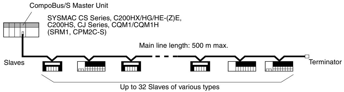
Connect up to 32 Slaves (256 Points) for Each Master Unit
Up to 32 Slaves of various types
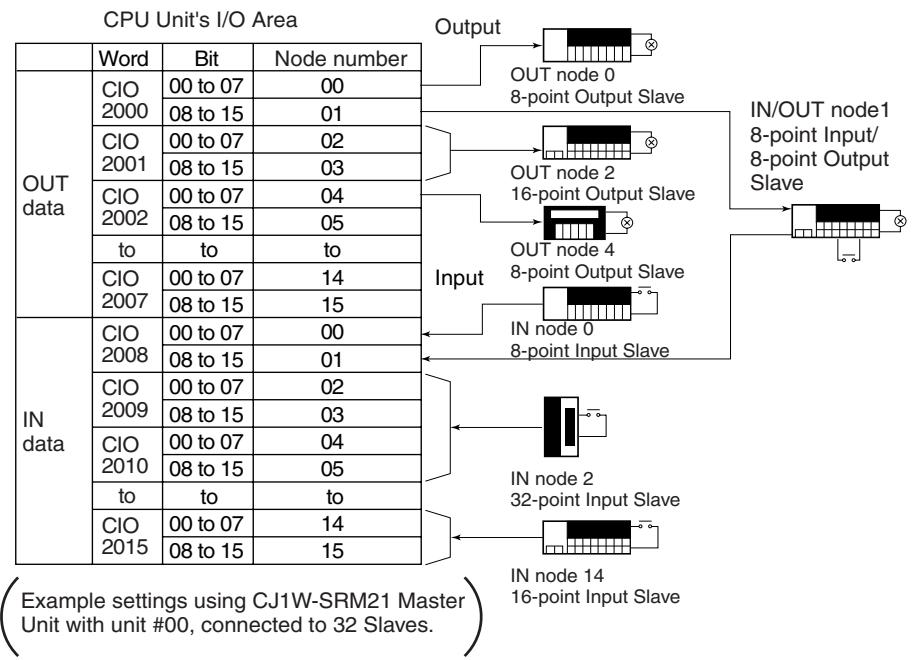
I/O Data Exchange without Special Programming
I/O data can be exchanged between the Master and Slaves without requiring any special ladder programming for communications. I/O information for each Slave is exchanged between Slaves and the corresponding I/O Area in the Master by simply setting the node number of each Slave.
Input Slave
1-1-2 Network Features
Communications Modes
The CompoBus/S has the following features.
Select either a High-speed Communications Mode or Long-distance Communications Mode for the CompoBus/S according to the system configuration. The differences between the High-speed Communications Mode and the Long-distance Communications Mode are described in 1-1-3 Communications Modes.
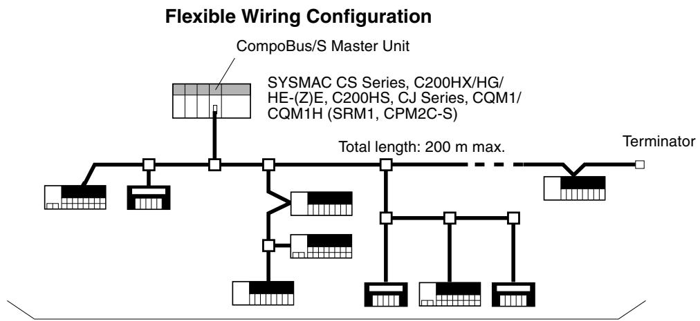
Flexible Wiring Up to 200 m
In Long-distance Communications Mode, flexible wiring is possible up to a total cable length of 200m with no restrictions on branching or node connections, provided that 4-conductor VCTF cable or Special Flat Cable is used.
Long-distance Communications Up to 500 m
In Long-distance Communications Mode, communications over the main line of up to 500m are possible to control I/O devices in a wide area, provided that 2-conductor VCTF cable is used. In this case, however, each branch line can be connected to a single Slave only, because the branch line cannot be further branched. Furthermore, the Master must be connected to either end of the main line.
High-speed Communications
In High-speed Communications Mode, up to 16 Slaves with 128 I/O points can be connected with a high-speed communications cycle time of only 0.5ms . This cycle is fast enough for time-critical factory automation applications.
Water-resistance Slaves
Water-resistant Terminals (IP67) can be used as Slaves to exchange I/O in places exposed to water. Water-resistant Terminals are, however, available only when the communications cable is 4-conductor VCTF cable.
Reduced Wiring
A Slave can be connected to a Master or another Slave with just one connecting cable. If the 4-wire Special Flat Cable or 4-conductor VCTF cable is used, the Slave's communication power supply is also supplied through the cable, so floor wiring can be reduced dramatically. Also, special connectors simplify branching from a main cable.
| Connecting to 4-conductor VCTF Cable | Easy-to-obtain 4-conductor VCTF cable can be used instead of the Special Flat Cable. Furthermore improvement in the environmental resistance of the system is possible by using shielded connectors. |
| Use Both T-branch and Multidrop Methods | Both the T-branch and multidrop methods can be combined flexibly when wiring. In combination with the floor cables, this wiring feature allows a very flexible system configuration. There are three types of cables (2-conductor VCTF cable, 4-conductor VCTF cable, and Special Flat Cable), and when the Special Flat Cable is used, T-branch Connectors can be installed by simply snapping the connector on. |
| Wide Variety of Masters | Master Units are available as Special I/O Units for the CS-series, C200HX/C200HG/C200HE-(Z)E, C200HS, CS-series, CJ-series, and CQM1 PLCs and also available integrated with a CPU for the SRM1 and CPM2C-S. The variety of Masters provides flexibility in configuring a system to match your application needs. |
| Wide Variety of Slaves | Units in a wide range are available as I/O Slaves for a variety of applications. Such Units include Remote Terminals and Sensor Terminals, which vary with the number of I/O points or I/O type, Connector Terminals, which allow easy wiring, and Water-resistant Terminals, which have a better protective construction. There are many Slaves available with advanced functions, including Analog I/O Terminals for analog-to-digital or digital-to-analog conversion, and CPM1A/CPM2A/CPM2C I/O Link Units for sharing data with the host PLC. |
| Easy Startup | The CompoBus/S System can be started just by wiring the cables and making some simple settings. Replacement of earlier Remote I/O Systems is also easy. |
| Slave Node Number Provided on Indicators and in PLC Memory | Troubleshooting is easy because the Slave's node number is shown on the Master's indicators if an error occurs with a Slave. When a CS-series, C200HX/HG/HE-(Z)E, or C200HS Master Unit is used, error information is also stored in PLC memory. When an error occurs with a Slave using a CS-series or CJ-series Master Unit, the Slave's node number is stored in the DM Area using the Slave registration function. |
| Slave Monitoring for Improved Reliability | Reliability of the CS-series and CJ-series Master Units has been further improved by the addition of the following functions. |
| Slave Registration FunctionRegistering Slaves in the Master allows the user to check whether connected Slaves are joined to the network, and to detect whether Slaves are illegally joined due to incorrect connection, or missing from the network due to a delay in startup or malfunction of registered Slaves. | |
| Communications Stop ModeSystem malfunctions can be avoided by setting remote I/O communications to stop when a communications error occurs. |
1-1-3 Communications Modes
Both High-speed Communications Mode and the Long-distance Communications Mode are supported by the CompoBus/S.
| Item | High-speed Communica-tions Mode | Long-distance Communi-cations Mode |
| Communications baud rate | 750 kbps | 93.75 kbps |
| Communications cycle time | 0.5 ms or 0.8 ms (depending on maximum number of I/O points) | 4.0 ms or 6.0 ms (depend- ing on maximum number of I/O points) |
The communications distance and the connection configuration vary with the communications mode and communications cable.
| Cable | High-speed Communications Mode | Long-distance Communica-tions Mode |
| 2-conductor VCTF cable | Length of main line: 100 m max. Length of branch line: 3 m max. Total length of branch lines: 50 m max. | Length of main line: 500 m max. Length of branch line: 6 m max. Total length of branch lines: 120 m max. |
| 4-conductor VCTF cable | Length of main line: 30 m max. Length of branch line: 3 m max. Total length of branch lines: 30 m max.. | Flexible branching, provided that the total length of cable is a maxi-mum of 200 m. |
| Special Flat Cable | Length of main line: 30 m max. Length of branch line: 3 m max. Total length of branch lines: 30 m max. | Flexible branching, provided that the total length of cable is a maxi-mum of 200 m. |
Note The I/O response time may be slower when using Long-distance Communications Mode compared with High-speed Communications Mode. Refer to 2-5 I/O Response Time Characteristics.
1-2 CompoBus/S System Configuration
1-2-1 Basic System Configuration
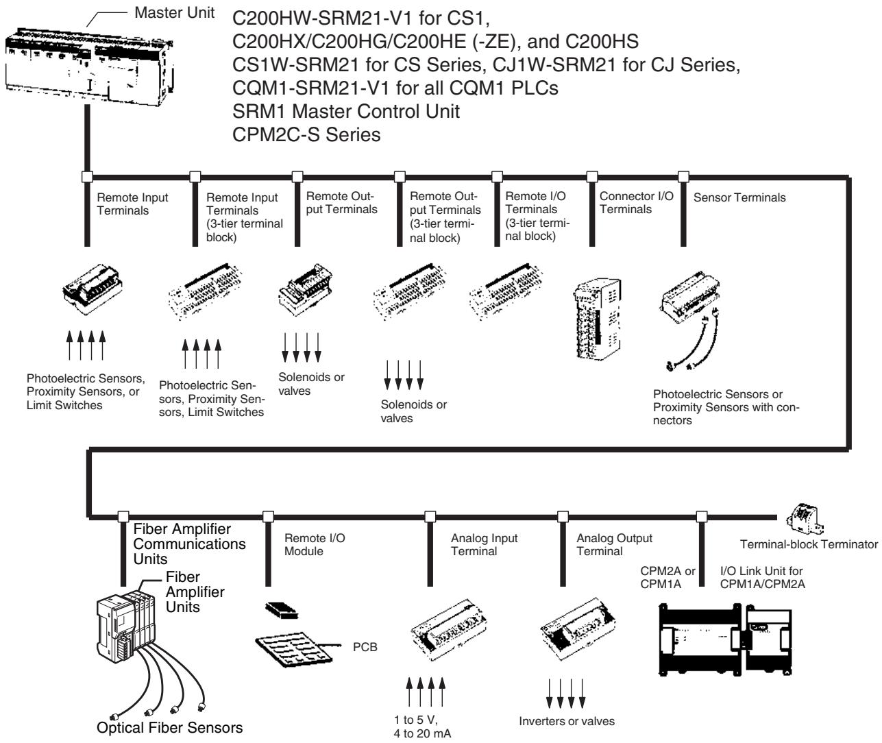
Master Characteristics
CS-series, C200HX/HG/HE-(Z)E, C200HS Master Units
- Multiple Masters (up to 16) can be connected to a single PLC.
- Up to 128 or 256 I/O points (DIP switch used to switch setting).
- Communications status stored in CPU Unit's I/O Area.
CS-series Master Units
- Multiple Masters (up to 96) can be connected to a single PLC.
- Up to 128 or 256 I/O points (DIP switch used to switch setting).
- Communications status stored in CPU Unit's I/O Area.
- Uses the Slave registration function to monitor which Slaves are joined to the network.
- Communications can be stopped when a communications error occurs.
CJ-series Master Units
- Multiple Masters (up to 40) can be connected to a single PLC.
- Up to 128 or 256 I/O points (DIP switch used to switch setting).
- Communications status stored in CPU Unit's I/O Area.
| CQM1 Master Units SRM1 and CPM2C-S Master Units with Built-in CPU Units Slave Characteristics Remote Terminals Remote Terminals (3-tier Terminal Blocks) Connector Terminals Water-resistant Terminals Remote I/O Modules Sensor Terminals Fiber Amplifier Communications Units Fiber Amplifier Communications Units Fiber Amplifier Communications Units Fiber Amplifier Communications Units Fiber Amplifier Communications Units Fiber Amplifier Communications Units Fiber Amplifier Communications Units Fiber Amplifier Communications Units Fiber Amplifier Communications Units Fiber Amplifier Communications Units Fiber Amplifier Communications Units Fiber Amplifier Communications Units Fiber Amplifier Communications Units Fiber Amplifier Communications Units Fiber Amplifier Communications Units Wireless Controller Wireless Controller Wireless Controller Wireless Controller Wireless Controller Wireless Controller Wireless Controller Wireless Controller Wireless Controller Wireless Controller Wireless Controller Wireless Controller Wireless Controller Wireless Controller Wireless Controller Wireless Controller Wireless Controller Wireless Controller Wireless Controller Wireless Controller Wireless Controller Wireless Controller Wireless Controller Wireless Controller Wireless Controller WirelessController WirelessController WirelessController WirelessController WirelessController WirelessController WirelessController WirelessController WirelessController WirelessController WirelessController WirelessController WirelessController WirelessController WirelessController WirelessController WirelessController WirelessController WirelessController WirelessController WirelessController WirelessController WirelessController WirelessController WirelessController Wireless Controller WirelessController WirelessController WirelessController WirelessController WirelessController WirelessController WirelessController WirelessController WirelessController WirelessController WirelessController WirelessController WirelessController WirelessController WirelessController WirelessController WirelessController WirelessController WirelessController WirelessController WirelessController WirelessController WirelessController Wireless Controller Wireless Controller Wireless Controller Wireless Controller Wireless Controller Wireless Controller Wireless Controller Wireless Controller Wireless Controller Wireless Controller Wireless Controller Wireless Controller Wireless Controller Wireless Controller Wireless Controller Wireless Controller Wireless Controller Wireless Controller Wireless Controller Wireless Controller Wireless Controller Wireless Controller Wireless Controller Wireless Controller Wireless controllers Wireless controllers Wireless controllers Wireless controllers Wireless controllers Wireless controllers Wireless controllers Wireless controllers Wireless controllers Wireless controllers Wireless controllers Wireless controllers Wireless controllers Wireless controllers Wireless controllers Wireless controllers Wireless controllers Wireless controllers Wireless controllers Wireless controllers Wireless controllers Wireless controllers Wireless controllers Wireless controllers Wireless controllers Wireless Controller Wireless Controller Wireless Controller Wireless Controller Wireless Controller Wireless Controller Wireless Controller Wireless Controller Wireless Controller Wireless Controller Wireless Controller Wireless Controller Wireless Controller Wireless Controller Wireless Controller Wireless Controller Wireless Controller Wireless Controller Wireless Controller Wireless Controller Wireless Controller Wireless Controller Wireless Controller Wireless Controller Wireless Controllers Wireless Controllers Wireless Controllers Wireless Controllers Wireless Controllers Wireless Controllers Wireless Controllers Wireless Controllers Wireless Controllers Wireless Controllers Wireless Controllers Wireless Controllers Wireless Controllers Wireless Controllers Wireless Controllers Wireless Controllers Wireless Controllers Wireless Controllers Wireless Controllers Wireless Controllers Wireless Controllers Wireless Controllers Wireless Controllers Wireless Controllers Wireless Controllers Wireless Controller Wireless Controller Wireless Controller Wireless Controller Wireless Controller Wireless Controller Wireless Controller Wireless Controller Wireless Controller Wireless Controller Wireless Controller Wireless Controller Wireless Controller Wireless Controller Wireless Controller Wireless Controller Wireless Controller Wireless Controller Wireless Controller Wireless Controller Wireless Controller Wireless Controller Wireless Controller Wireless Controller Wireless控制器 Wireless控制器 Wireless控制器 Wireless控制器 Wireless控制器 Wireless控制器 Wireless控制器 Wireless控制器 Wireless控制器 Wireless控制器 Wireless控制器 Wireless控制器 Wireless控制器 Wireless控制器 Wireless控制器 Wireless控制器 Wireless控制器 Wireless控制器 Wireless控制器 Wireless控制器 Wireless控制器 Wireless控制器 Wireless控制器 Wireless控制器 Wireless控制器 Wireless Controller Wireless Controller Wireless Controller Wireless Controller Wireless Controller Wireless Controller Wireless Controller Wireless Controller Wireless Controller Wireless Controller Wireless Controller Wireless Controller Wireless Controller Wireless Controller Wireless Controller Wireless Controller Wireless Controller Wireless Controller Wireless Controller Wireless Controller Wireless Controller Wireless Controller Wireless Controller Wireless Controller Wireless controller Wireless controller Wireless controller Wireless controller Wireless controller Wireless controller Wireless controller Wireless controller Wireless controller Wireless controller Wireless controller Wireless controller Wireless controller Wireless controller Wireless controller Wireless controller Wireless controller Wireless controller Wireless controller Wireless controller Wireless controller Wireless controller Wireless controller Wireless controller Wireless controller Wireless Controller Wireless Controller Wireless Controller Wireless Controller Wireless Controller Wireless Controller Wireless Controller Wireless Controller Wireless Controller Wireless Controller Wireless Controller Wireless Controller Wireless Controller Wireless Controller Wireless Controller Wireless Controller Wireless Controller Wireless Controller Wireless Controller Wireless Controller Wireless Controller Wireless Controller Wireless Controller Wireless Controller Wireless |
| Analog Input Terminals | ·Mobile Console can be connected without the Head (Photoelectric Sensor setting, teaching, and adjustment can be executed on site.) |
| ·Convert analog inputs to binary data. | |
| ·The number of analog input points can be switched between 4 points, 3 points, 2 points, and 1 point using a DIP switch. | |
| ·The following input ranges are supported:0 to 5 V, 1 to 5 V, 0 to 10 V, -10 to 10 V, 0 to 20 mA, 4 to 20 mA | |
| Analog Output Terminals | ·Convert binary data to analog outputs. |
| ·The number of analog output points can be switched between 2 points and 1 point using a DIP switch. | |
| ·Supports the following output ranges:1 to 5 V, 0 to 10 V, -10 to 10 V, 0 to 20 mA, 4 to 20 mA |
I/O Link Terminals for CPM1A/CPM2A
- Create I/O Links (8 inputs, 8 outputs) with CPM1A and CPM2A PLCs.
CPM2C I/O Link Unit
- Creating I/O Links (8 inputs, 8 outputs) with CPM2C-series PLCs.
1-2-2 CompoBus/S System Components
System with Distinct Main and Branch Lines
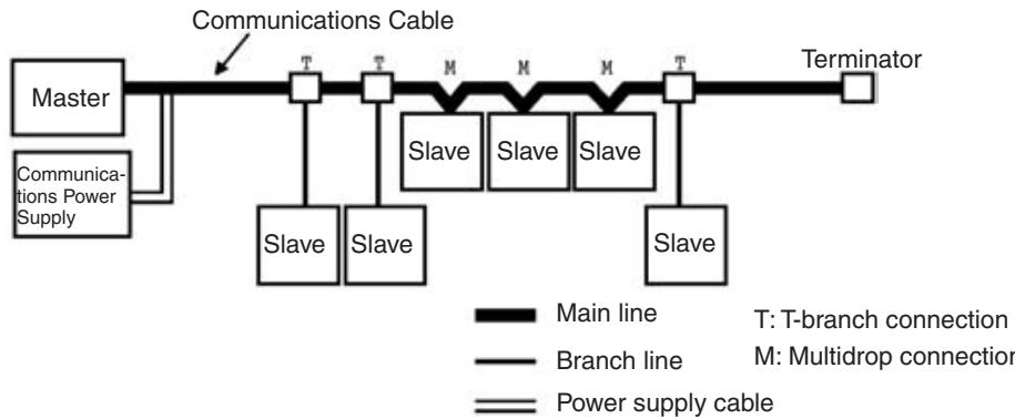
The diagram below shows a CompoBus/S System in which the main line must be distinguished from the branch lines under either of the following conditions.
- The system operates in High-speed Communications Mode.
- The system operates in Long-distance Communications Mode with 2-conductor VCTF cable. (The maximum length of the main line varies with the type of communications cable.)
Master
The Master administers the CompoBus/S System and manages the external I/O of the Slaves. There is only 1 Master in a CompoBus/S System and the Master must be connected at the end of the main line, as shown in the preceding diagram.
Slaves
The external I/O connected to the Slaves is processed by communicating with the Master through the CompoBus/S System.
Main/Branch Lines
The main line is the main cable that connects the two most distant points of the system. Cables branching from the main line are known as branch lines.
Cables
CompoBus/S communications are transmitted through 2-conductor VCTF, 4-conductor VCTF, or Special Flat Cable. When 4-conductor VCTF or Special
| Flat Cable is used, the communications power supply can be supplied through the cable. The system shown in the preceding diagram uses 4-conductor VCTF or Special Flat Cable. When 2-conductor VCTF cable is used, power must be supplied to the Slaves through a separate cable. | |
| Connection Methods | Two methods can be used to connect CompoBus/S Slaves: the T-branch method and the multidrop method. With the T-branch method, the Slave is connected to a branch line which branches off from the main line. With the multidrop method, the Slave is connected directly to the main line.These two connection methods can both be used in the same system, although it is not possible to make a secondary branch from a branch line. Use OMRON's Branch Connector, a T-joint for a shielded connector, or a commercially available terminal block to create a branch from the main line. |
| Terminator | A terminator must be connected to the end of the main line opposite the Master in order to stabilize communications. There are three kinds of terminating resistors available, a connector for use with Special Flat Cable, a terminal block, and a shielded connector. |
System with No Distinction between Main and Branch Lines
The diagram below shows a CompoBus/S System in which it is not necessary to distinguish between the main line and branch lines. This applies to the following conditions.
- The system operates in Long-distance Communications Mode with 4-conductor VCTF cable.
- The system operates in Long-distance Communications Mode with Special Flat Cable.
(The maximum length of cable is 200m regardless of the type of communications cable.)
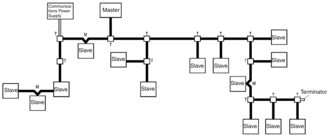

Communications cable Power supply cable
T: T-branch connection
M: Multidrop connection
Master
The Master administers the CompoBus/S System and manages the external I/O of the Slaves. There is only one Master in a CompoBus/S System and the Master can be connected anywhere.
Slaves
The external I/O connected to the Slaves is processed by communicating with the Master through the CompoBus/S System.
Cables
CompoBus/S communications are transmitted through Special Flat Cable or 4-conductor VCTF cable. The communications power supply can be supplied through either of the cables.
Connection Methods
Two methods can be used to connect the CompoBus/S Master and Slaves: the T-branch method and the multidrop method. With the T-branch method, the Slave is connected to a line that branches off from the communications cable wherever desired. With the multidrop method, the Master or Slave is connected directly to the communications cable. These two connection methods can both be used in the same system and it is possible to make a secondary branch from a branch line. Use OMRON's Branch Connector for Special Flat Cable, a T-joint for a shielded connector, or a commercially available terminal block to create a branch from the communications cable.
Terminator
A terminator must be connected to the end of the communications cable farthest from the Master in order to stabilize communications. There are three kinds of terminating resistors available, a connector for use with Special Flat Cable, a terminal block, and a shielded connector. In a system in which distinguishing between the main and branch lines is not necessary, only a single terminator farthest from the Master is required regardless of the position the Master is connected to the communications cable.
1-3 Compatible Devices
1-3-1 Compatible Masters
Masters with
Communications
Functions
There are three types of Master Units which can be used in CompoBus/S Systems. The model of the Master Unit which must be used depends on the PLC being used.
| PLC | C200HX-CPU3☐-(Z)E/ CPU4☐-(Z)E, C200HG-CPU3☐-(Z)E/CPU4☐-(Z)E, C200HE, C200HS | C200HX-CPU5☐-(Z)E/ CPU6☐-(Z)E/ CPU8☐-(Z)E, C200HG-CPU5☐-(Z)E/ CPU6☐-(Z)E, CS Series | CS Series | CJ Series | CQM1, CQM1H |
| Master Unit | C200HW-SRM21-V1 | CS1W-SRM21 | CJ1W-SRM21 | CQM1-SRM21-V1 | |
| Communications mode | High-speed Communications Mode or Long-distance Communications Mode (switched using the DIP switch on front panel) | ||||
| Analog I/O Terminal connection | Possible | ||||
| Max. number of Masters | 10 Units (when using a single Spe-cial I/O Unit node number (i.e., 10 words))5 Units (when using two Special I/O Unit node number (i.e., 20 words)) | 16 Units (when using a single Spe-cial I/O Unit node number (i.e., 10 words))8 Units (when using two Special I/O Unit node number (i.e., 20 words)) | 96 Units (when using a single Spe-cial I/O Unit node number (i.e., 10 words))95 Units (when using two Special I/O Unit node number (i.e., 20 words)) | 40 Units | CQM1: 1 UnitCQM1H: Up to the number corresponding to the maximum I/O points for the CPU Unit. |
| Master Unit mounting location | Can be mounted on the CPU Backplane or Expansion I/O Back-plane. Can't be mounted on a SYSMAC BUS Slave (RT) Rack. | Can be connected in the CPU Rack or Expansion Rack. | No restrictions. | ||
| Max. number of I/O points per Master | 256 points (128 inputs/128 outputs) or 128 points (64 inputs/64 outputs)The max. number of I/O points depends on the DIP switch settings.The area allocated to Special I/O Units is used for I/O. | CQM1-CPU11-E/21-E:32 points (16 inputs/16 outputs) or64 points (32 inputs/32 outputs)CQM1-CPU41-EV1/42-EV1/43-EV1/44-EV1:32 points (16 inputs/16 outputs)or64 points (32 inputs/32 outputs)or128 points(64 inputs/64 outputs)The max. number ofI/O points depends on the DIP switch settings.The IR area is used for I/O. | |||
| Number of points per node number | 8-point mode | 8-point mode | 8-point mode or 4-point mode | ||
| Number of usable node numbers per Master | IN0 to IN7 and OUT0 to OUT7 or IN0 toIN15 and OUT0 to OUT15 | IN0 to IN7 and OUT0 to OUT7 or IN0 toIN15 and OUT0 to OUT15 | When 8 points are used per node:IN0 to IN1/OUT0to OUT1 orIN0 to IN3/OUT0to OUT3 orIN0 to IN7/OUT0to OUT7When 4 points are used per node:IN0 to IN3/OUT0to OUT3 orIN0 to IN7/OUT0to OUT7 orIN0 to IN15/OUT0to OUT15 | ||
| Master Unit power supply | Not required.(Power is supplied from the PLC.) | Not required.(Power is supplied from the PLC.) | Not required.(Power is supplied from the PLC.) | ||
| Terminal for connecting communications power supply for Slaves | Not provided | Provided | Not provided | ||
| Status indicators | The PLC's AR Area contains the active node flags and communications error flags for each Slave. | The PLC's Auxiliary Area contains the active node flags and communications error flags for each Slave. The DM Area contains an area for Slave registration and setting communications stop mode. | There is an alarm output terminal in the terminal block. | ||
Note
- Previous Master Unit models (without -V1), which do not support the Long-distance Communications Mode, cannot be used when an Analog I/O Terminal is connected as a Slave. If used, incorrect data may be transmitted.
- Refer to SECTION 4 Master Unit Specifications and Operations for more details on the Master Units.
Master with Built-in CPU
The following Master Control Unit models, which have a built-in CPU Unit, are used for distributed I/O control in CompoBus/S Systems. Refer to the SRM1 Master Control Unit Operation Manual (W318-E1-□) and the CPM2C-S PLC Operation Manual (W377-E1-□) for details.
SRM1 Master Control Unit
| Item | Master Control Unit | |
| SRM1-CPU01-V2 | SRM1-CPU02-V2 | |
| Peripheral port | Yes | Yes |
| RS-232C port | --- | Yes |
| Program capacity | 4K words | |
| Max. number of I/O points | 256 (128 inputs/128 outputs) | |
| Communications mode | High-speed Communications Mode or Long-distance Communications Mode (switched using PLC Setup) | |
| Number of points per node number | 8-point mode | |
| Number of usable node numbers per Master | IN0 to IN7 and OUT0 to OUT7 or IN0 to IN15 and OUT0 to OUT15 | |
| Status indicators | The PLC's AR Area contains the active node flags and communications error flags for each Slave. | |
CPM2C-SPLC
The CPM2C-S PLC has built-in CompoBus/S Master and DeviceNet Slave functions. Models that support I/O links with host PLCs are available as well.
| Item | Master Control Unit | |
| CPM2C-S□□□C | CPM2C-S□□□C-DRT | |
| Peripheral port | The same connector is used. | |
| RS-232C port | ||
| Program capacity | 4K words | |
| Max. number of I/O points | 256 (128 inputs/128 outputs) | |
| Communications mode | High-speed Communications Mode or Long-distance Communications Mode (switched using PLC Setup) | |
Master Units and Corresponding Communications Modes
| Item | Master Control Unit | |
| CPM2C-S□□□C | CPM2C-S□□□C-DRT | |
| Number of points per node number | 8-point mode | |
| Number of usable node numbers per Master | IN0 to IN7 and OUT0 to OUT7 or IN0 to IN15 and OUT0 to OUT15 | |
| Status indicators | The PLC's AR Area contains the active node flags and communications error flags for each Slave. | |
| DeviceNet Slave function | Not provided | Provided |
Master Units support only High-speed Communications Mode or both High-speed Communications Mode and Long-distance Communications Mode.
Slave Analog Terminals can be connected to the Units that support both High-speed and Long-distance Communications Modes. These Units are an upgraded version and, by switching the communications mode, can be used instead of the Units that support only the High-speed Communications Mode.
| Item | Unit supporting High-speed Communications only | Unit supporting High-speed and Long-distance Communications | |
| Communications modes | High-speed Communications Mode | Yes | Yes |
| Long-distance Communications Mode | No | Yes | |
| Analog I/O Terminal connections | No | Yes | |
The following models are available.
| PLC | Units supporting High-speed Communications | Units supporting High-speed and Long-distance Communications |
| CS-series, C200HX/C200HG/ C200HE-(Z)E, and C200HS Master Units | C200HW-SRM21 | C200HW-SRM21-V1 |
| CS-series Master Units | --- | CS1W-SRM21 |
| CJ-series Master Units | --- | CJ1W-SRM21 |
| CQM1 Master Units | CQM1-SRM21 | CQM1-SRM21-V1 |
| SRM1 | SRM1-C0□SRM1-C0□-V1 | SRM1-C0□-V2 |
| CPM2C-S | --- | CPM2C-S□□□ (-DRT) |
Note Master Units that do not support Long-distance Communications Mode cannot be used when connecting an Analog Terminal as a Slave. If used, incorrect data may be transmitted.
1-3-2 Slave Units
The SRT1/SRT2 Series provides Slaves that support only High-speed Communications Mode or both High-speed Communications Mode and Long-distance Communications Mode. The SRT2-series Slaves that support High-speed and Long-distance Communications Modes are an upgraded version
and, by switching the communications mode, can be used instead of the Slaves that support only the High-speed Communications Mode.
| Item | Slaves supporting High-speed Communications | Slaves supporting High-speed and Long-distance Communications | |
| Slave Series | SRT1 Series | SRT2 Series | |
| Communications modes | High-speed Communications Mode | Yes | Yes |
| Long-distance Communications Mode | No | Yes | |
Available models are shown in the following table.
| Type | Previous models | New models | I/O points | Power supply |
| Slave | SRT1 Series | SRT2 Series | ||
| Remote Terminals with Transistors | SRT1-ID04 | SRT2-ID04 | 4 inputs (NPN) | Multiple supplies |
| SRT1-ID04-1 | SRT2-ID04-1 | 4 inputs (PNP) | ||
| SRT1-ID08 | SRT2-ID08 | 8 inputs (NPN) | ||
| SRT1-ID08-1 | SRT2-ID08-1 | 8 inputs (PNP) | ||
| SRT1-ID16 | SRT2-ID16 | 16 inputs (NPN) | ||
| SRT1-ID16-1 | SRT2-ID16-1 | 16 inputs (PNP) | ||
| SRT1-ID16T | SRT2-ID16T | 16 inputs (NPN, 3-tier terminal block) | ||
| SRT1-ID16T-1 | SRT2-ID16T-1 | 16 inputs (PNP, 3-tier terminal block) | ||
| SRT1-OD04 | SRT2-OD04 | 4 outputs (NPN) | ||
| SRT1-OD04-1 | SRT2-OD04-1 | 4 outputs (PNP) | ||
| SRT1-OD08 | SRT2-OD08 | 8 outputs (NPN) | ||
| SRT1-OD08-1 | SRT2-OD08-1 | 8 outputs (PNP) | ||
| SRT1-OD16 | SRT2-OD16 | 16 outputs (NPN) | ||
| SRT1-OD16-1 | SRT2-OD16-1 | 16 outputs (PNP) | ||
| SRT1-OD16T | SRT2-OD16T | 16 outputs (NPN, 3-tier terminal block) | ||
| SRT1-OD16T-1 | SRT2-OD16T-1 | 16 outputs (PNP, 3-tier terminal block) | ||
| SRT1-MD16T | SRT2-MD16T | 8 inputs, 8 outputs (NPN, 3-tier terminal block) | ||
| SRT1-MD16T-1 | SRT2-MD16T-1 | 8 inputs, 8 outputs (PNP, 3-tier terminal block) | ||
| Connector Terminals (8-point/16-point Transistors) | None | SRT2-VID08S | 8 inputs(NPN, sensor connectors) | Multiple supplies |
| SRT2-VID08S-1 | 8 inputs(PNP, sensor connectors) | |||
| SRT2-VID16ML | 16 inputs(NPN, MIL connectors) | |||
| SRT2-VID16ML-1 | 16 inputs(PNP, MIL connectors) | |||
| SRT2-VOD08S | 8 outputs(NPN, sensor connectors) | |||
| SRT2-VOD08S-1 | 8 outputs(PNP, sensor connectors) | |||
| SRT2-VOD16ML | 16 outputs(NPN, MIL connectors) | |||
| SRT2-VOD16ML-1 | 16 outputs(PNP, MIL connectors) | |||
| Connector Terminals (32-point Transistors) | None | SRT2-ID32ML | 32 inputs(NPN, MIL connectors) | |
| SRT2-ID32ML-1 | 32 inputs(PNP, MIL connectors) | |||
| SRT2-OD32ML | 32 outputs(NPN, MIL connectors) | |||
| SRT2-OD32ML-1 | 32 outputs(PNP, MIL connectors) | |||
| SRT2-MD32ML | 16 inputs, 16 outputs(NPN, MIL connectors) | |||
| SRT2-MD32ML-1 | 16 inputs, 16 outputs(PNP, MIL connectors) | |||
| Remote Terminals with Relays | SRT1-ROC08 | SRT2-ROC08 | 8 outputs | Local |
| SRT1-ROC16 | SRT2-ROC16 | 16 outputs | ||
| Remote Terminals with Power MOS FETs | SRT1-ROF08 | SRT2-ROF08 | 8 outputs | |
| SRT1-ROF16 | SRT2-ROF16 | 16 outputs | ||
| Water-resistant Terminals (Transistors) | None | SRT2-ID04CL | 4 inputs(NPN) | Multiple supplies |
| SRT2-ID04CL-1 | 4 inputs(PNP) | |||
| SRT2-ID08CL | 8 inputs(NPN) | |||
| SRT2-ID08CL-1 | 8 inputs(PNP) | |||
| SRT2-OD04CL | 4 outputs(NPN) | |||
| SRT2-OD04CL-1 | 4 outputs(PNP) | |||
| SRT2-OD08CL | 8 outputs(NPN) | |||
| SRT2-OD08CL-1 | 8 outputs(PNP) | |||
| Sensor Terminals | SRT1-ID08S | SRT2-ID08S | 8 inputs | Network |
| SRT1-ND08S | SRT2-ND08S | 4 inputs, 4 outputs | ||
| SRT1-OD08S | SRT2-OD08S | 8 outputs(NPN, connector outputs) | Local | |
| Remote I/O Mod-ules | SRT1-ID16P | SRT2-ID16P | 16 inputs(NPN, PCB attachment) | --- |
| SRT1-OD16P | SRT2-OD16P | 16 outputs(NPN, PCB attachment) | ||
| Fiber Amplifier Communications Unit | None | E3X-SRT21 | 8-point input or 16 point input (with Fiber Amplifier Unit connected) | Network |
| Analog Input Terminals | None | SRT2-AD04 | Switchable between 4-point, 3-point, 2-point, and 1-point analog input | |
| Analog Output Terminus | None | SRT2-DA02 | Switchable between 2-point and 1-point analog output | |
| I/O Link Units | None | CPM1A-SRT21 | 8 inputs, 8 outputs (For CPM1A/CPM2A) | --- |
| CPM2C I/O Link Units | None | CPM2C-SRT21 | 8 inputs, 8 outputs (For CPM2C) | --- |
Note
- The power supply requirements are described below. Refer to 2-3 Supplying Power to the Slaves for details on these power supplies.
- Refer to SECTION 5 Slave Specifications and Operations for details on Slaves.
Network Power Supply
These Slaves use a single power supply and can be supplied with power from the Special Flat Cable for CompoBus/S.
Multiple Power Supplies
These Slaves require two separate power supplies for communications and I/O.
The communications power can be supplied from the Special Flat Cable for CompoBus/S.
Local Power Supply
These Slaves require a single external power supply. The power cannot be supplied from the Special Flat Cable for CompoBus/S.
1-3-3 Cables
Cables
The following table lists the cables that can be used in a CompoBus/S System.
| Cable | Specifications |
| 2-conductor VCTF cable (sold commercially) | Vinyl-clad VCTF JIS C 3306 Two 0.75 mm² conductors (2 signal wires) Resistance: 25.1 Ω/km at 20°C Use only 2-conductor VCTF cable. |
| 4-conductor VCTF cable (sold commercially) | Vinyl-clad VCTF JIS C 3306 Four 0.75 mm² conductors (2 signal wires and 2 power supply wires) Resistance: 25.1 Ω/km at 20°C. |
| Special Flat Cable (OMRON SCA1-4F10, 100 m) | Four 0.75 mm² conductors (2 signal wires and 2 power supply wires) Maximum ambient temperature: 60°C |
Note
- Do not use cables other than those specified above.
- For information on communications cables specified by overseas manufacturers, refer to Appendix Standard Models.
The communications distance depends on the cable used, as follows:
| Cable | Mode | Main line length | Branch line length | Total branch line length |
| 2-conductor VCTF cable | High-speed Commu-nications Mode | 100 m max. | 3 m max. | 50 m max. |
| Long-distance Commu-nications Mode | 500 m max. | 6 m max. | 120 m max. | |
| 4-conductor VCTF cable | High-speed Commu-nications Mode | 30 m max. (See note.) | 3 m max. (See note.) | 30 m max. (See note.) |
| Long-distance Commu-nications Mode | Flexibly branched, provided that the total length of cable is a maximum of 200 m. | |||
| Special Flat Cable | High-speed Commu-nications Mode | 30 m max. (See note.) | 3 m max. (See note.) | 30 m max. (See note.) |
| Long-distance Commu-nications Mode | Flexibly branched, provided that the total length of cable is a maximum of 200 m. | |||
Note When 4-conductor VCTF cable or Special Flat Cable is used to connect fewer than 16 Slaves, the main line can be up to 100m long and the total branch line length can be up to 50m in High-speed Communications Mode. (These are the same conditions as when 2-conductor VCTF cable is used.)
1-3-4 Connectors/Terminal Blocks
The following table lists the connectors that can be used in a CompoBus/S System.
| Connector | Model | Comments |
| Branch Connector | SCN1-TH4 | Use this connector to create a branch line from the main line. (Used with Special Flat Cable only.) |
| Extension Connector | SCN1-TH4E | Use this connector to extend the Special Flat Cable. |
| Connector Terminator | SCN1-TH4T | This connector has a built-in terminator. (Used with Special Flat Cable only.) |
| Connectors with Cable with a socket and plug | XS2W-D42☐-☐81☐ | Connectors with cable used to connect the Water-resistant Terminal to a T-joint. Can be used as a power supply cable (with the female socket connected to the Water-resistant Terminal). Can be used as an I/O cable for sensors that have connectors (with the male plug connected to the Water-resistant Terminal, if the product has a model number suffix “A”). |
| Connector with Cable with a female socket | XS2F-D42☐-☐80☐ | A connector with cable used to connect the Water-resistant Terminal to a T-branch connector. Can be used as a power supply cable (with the female socket connected to the Water-resistant Terminal) and the other end wired to a commercially available terminal block. |
| Connector with Cable with a male plug | XS2H-D421-☐80-A | A connector with a cable used to connect the Water-resistant Terminal to an I/O device. Can be used as an I/O cable (with the male plug connected to the Water-resistant Terminal) and the other end wired to the I/O device. |
| Connector Socket Assembly(female for screw, crimp, solder terminals) | XS2C-D4S7 | A connector used to connect to the communications connector or external power supply connector of the Water-resistant Terminal or a T-joint plug. Applicable cable dia.: 6 to 8 mmApplicable conductor size: 0.18 to 0.75 mm2 |
| XS2C-D4□□ | A connector used to connect to the external power supply connector of the Water-resistant Terminal or a T-joint plug. Applicable cable dia.: 3 to 6 mmApplicable conductor size: 0.18 to 0.3 or 0.5to 0.75 mm2 | |
| Connector Plug Assembly(male for screw, crimp, solder terminals) | XS2G-D4S7 | A connector used to connect to the T-joint socket. Applicable cable dia.: 6 to 8 mmApplicable conductor size: 0.18 to 0.75 mm2 |
| XS2G-D4□□ | A connector used to connect to the I/O connector of the Water-resistant Terminal or a T-joint socket. Applicable cable dia.: 3 to 6 mmApplicable conductor size: 0.18 to 0.3 or 0.5to 0.75 mm2 | |
| T-joint | XS2R-D427-5 | A joint used to T-branch a VCTF cable (e.g., a communications cable or power supply cable). |
| Communications Connector(6 pins) | FK-MCP1.5/6-STF-3.81 | A communications connector for connecting CJ-series Master Units. The connector can be connected simultaneously to the communications cable (BD H, BD L, BS+, BS-) and communications power supply (BS+, BS-).This connector has screwless terminals for signal lines and connector lock screws. |
| MC1.5/6-STF-3.81 | A communications connector for connecting CJ-series Master Units. The connector can be connected simultaneously to the communications cable (BD H, BD L, BS+, BS-) and communications power supply (BS+, BS-).This connector has screw terminals for signal lines and connector lock screws. | |
| Shielded Terminator Plug(Male) | SRS2-1 | A shielded connector terminator model con- nected to a T-joint. |
| Terminal-block Terminator | SRS1-T | This terminal block has a built-in terminator. (Can be used with VCTF cable and Special Flat Cable.) |
Note 1. Connect a terminator (Connector Terminator, Shield Terminator, or Terminal-block Terminator) to the following point in the system.
- System with Distinction between Main and Branch Lines: The end of the main line farthest from the Master.
-
System with No Distinction Main and Branch Lines: The end of the communications cable farthest from the Master.
-
Use a commercially available terminal block or T-joint to branch or extend VCTF cable.
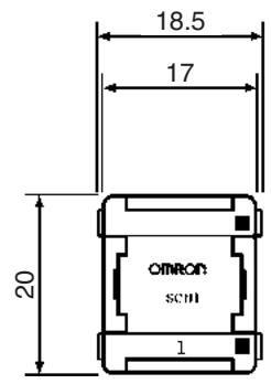
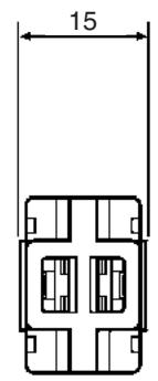
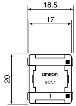
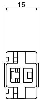
Dimensions
The following diagram shows the dimensions (after assembly). All dimensions are in mm.
SCN1-TH4 Branch Connector
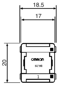
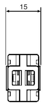
SCN1-TH4E Extension Connector
SCN1-TH4T Connector Terminator
Connectors with Cables
XS2W-D42-□81-(socket and plug)

XS2F-D42□-□80-(socket on one end)
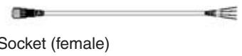
XS2H-D421-80-A (plug on one end)

Connector Assembly
Socket (Female)
(Crimp terminals/Solder terminals)
XS2C-D4S7 (Communications)
XS2C-D4□□ (Power supply and I/O)

Socket (female)
Plug (Male)
(Crimp terminals/Solder terminals)
XS2G-D4S7 (Communications)
XS2G-D4□□ (Power supply and I/O)

Plug (male)
XS2R-D427-5 T-joint
Socket (female)
Socket (female)
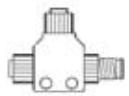
Plug (male)
SRS2-1 Shield Terminator Plug (male)

Plug (male)
SRS1-T Terminal-block Terminator
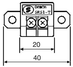
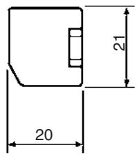
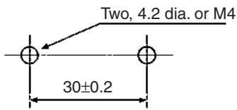
Mounting Holes
1-4 Startup Procedure
Selecting Master and Slave
The standard procedure for starting up the CompoBus/S System is as follows:
Select the Master and Slaves according to the following items.
- PLC model being used (Refer to 1-3-1 Compatible Masters and SECTION 4 Master Unit Specifications and Operations.)
- Number of Slaves (Refer to 1-3-1 Compatible Masters)
Maximum I/O points (Refer to 1-3-1 Compatible Masters) - Slave I/O types (Refer to 1-3-2 Slave Units and SECTION 5 Slave Specifications and Operations)
Determining the Communications Mode
Determine the communications mode according to the following items.
- Communications distance (Refer to 2-2-2 Maximum Cable Length)
- I/O response time (Refer to 2-5 I/O Response Time Characteristics)
Determining System Configuration
Determine the CompoBus/S System configuration according to the following items. Select the devices required for connection (such as connectors, terminal blocks, and terminators) according to the system configuration.
| • Arrangement of Master and Slaves (Refer to page 8 and page 25.) • Cable types applicable for the communications distance and communications mode (Refer to page 16 and page 29.) • Connection methods (Refer to page 8 and page 27.) • Methods for supplying communications and I/O power supplies (Refer to page 31.) • Connectors and terminal block models (Refer to page 6 and page 27.) | |
| Setting the Master Unit | Set the Master Unit according to the model used, referring to SECTION 4 Master Unit Specifications and Operations. |
| CS-series, C200HX/HG/HE-(Z)E, and C200HS Master Units (C200HW-SRM21-V1) • Special I/O Unit unit number • Number of nodes that can be connected • Communications mode | |
| CS-series Master Units (CS1W-SRM21) • Special I/O Unit unit number • Number of nodes that can be connected • Communications mode • Slave registration function (Set in DM Area while connected to the PLC.) • Communications stop mode setting function | |
| CJ-series Master Units • Special I/O Unit unit number • Number of nodes that can be connected • Communications mode • Slave registration function (Set in DM Area while connected to the PLC.) • Communications stop mode setting function | |
| CQM1 Master Units • Number of words allocated to the CPU • Number of bits allocated for each node number • Communications mode | |
| Setting the Slaves | Set the Slave Units, referring to SECTION 5 Slave Specifications and Operations. • Node number • Communications mode • Settings specific to each Slave (such as output holding/clearing when communications errors occur) |
| Wiring | Wire and connect the communications cables, communications power supply, I/O power supply, referring to the device specifications in SECTION 4 Master Unit Specifications and Operations, SECTION 5 Slave Specifications and Operations, and wiring information in SECTION 3 CompoBus/S System Wiring. |
| Starting and Checking Operations | Start the CompoBus/S System and check the Master and Slave operations, referring to SECTION 6 Starting Communications. |
| Starting Operations | Start operating the Master and Slaves. |
SECTION 2
CompoBus/S System Specifications and Configuration
This section provides information on CompoBus/S System specifications, methods used to configure a CompoBus/S System, and I/O response times.
2-1 Communications Specifications 24
2-2 System Configuration 25
2-2-1 Main Line/Branch Line Connections 25
2-2-2 Maximum Cable Length. 29
2-2-3 Terminator Connection 31
2-3 Supplying Power to the Slaves 31
2-3-1 Using 2-conductor VCTF Cable. 33
2-3-2 Using 4-conductor VCTF or Special Flat Cable. 34
2-3-3 Limitations of Communications Cable Power Supply 35
2-4 System Configuration Using Water-resistant Terminals 41
2-5 I/O Response Time Characteristics 41
2-5-1 Slaves Other Than Analog Terminals 42
2-5-2 Slave Analog Terminals 46
2-5-3 Slave I/O Delay Times 51
2-1 Communications Specifications
This section provides specifications for the CompoBus/S System.
| Item | Specification | |
| Communications method | Special CompoBus/S protocol | |
| Communications baud rate | High-speed Communications Mode: 750 kbps Long-distance Communications Mode: 93.75 kbps | |
| Modulation method | Baseband method | |
| Coding method | Manchester coding method | |
| Error control checks | Manchester code check, frame length check, and parity check | |
| Cable | VCTF cable (JIS C 3306) | Two 0.75 mm² conductors (2 signal wires) Four 0.75 mm² conductors (2 signal wires and 2 power supply wires) |
| Special Flat Cable | Four 0.75 mm² conductors (2 signal wires and 2 power supply wires) | |
| Communications distance | 2-conductor VCTF cable | High-speed Communications Mode Main line length: 100 m max. Branch line length: 3 m max. Total branch line length: 50 m max. |
| Long-distance Communications Mode Main line length: 500 m max. Branch line length: 6 m max. Total branch line length: 120 m max. | ||
| 4-conductor VCTF cable | High-speed Communications Mode Main line length: 30 m max. Branch line length: 3 m max. Total branch line length: 30 m max. | |
| Long-distance Communications Mode: Flexibly branched, provided that the total length of cable is a maximum of 200 m. | ||
| Special Flat Cable | High-speed Communications Mode Main line length: 30 m max. Branch line length: 3 m max. Total branch line length: 30 m max. When 4-conductor VCTF cable or Special Flat Cable is used to connect fewer than 16 Slaves, the main line can be up to 100 m long and the total branch line length can be up to 50 m in High-speed Communications Mode. | |
| Long-distance Communications Mode: Flexibly branched, provided that the total length of cable is a maximum of 200 m. | ||
| I/O points, Slaves, usable node numbers, and communications cycle time | C200HW-SRM21-V1 Master Unit (used for CS-series, C200HX/C200HG/C200HE-(Z)E, and C200HS PLCs), CS1W-SRM21 Master Unit (used for CS-series PLCs), CJ1W-SRM21 Master Unit (used for CJ-series PLCs), SRM1 Master Control Unit, and CPM2C-S PLC. | |
| Max. number of I/O points: 64 inputs/64 outputs Usable node numbers: IN0 to IN7 and OUT0 to OUT7 Communications cycle time: High-speed Communications Mode: 0.5 ms Long-distance Communications Mode: 4.0 ms | ||
| Max. number of I/O points: 128 inputs/128 outputs Usable node numbers: IN0 to IN15 and OUT0 to OUT15 Communications cycle time: High-speed Communications Mode: 0.8 ms Long-distance Communications Mode: 6.0 ms | ||
| CQM1-SRM21-V1 Master Unit (Used in CQM1 PLCs.) | ||
| Max. number of I/O points: 64 inputs/64 outputs Usable node numbers: IN0 to IN7 and OUT0 to OUT7 (8-point mode) Communications cycle time: High-speed Communications Mode: 0.5 ms Long-distance Communications Mode: 4.0 ms Usable node numbers: IN0 to IN15 and OUT0 to OUT15 (4-point mode) Communications cycle time: High-speed Communications Mode: 0.8 ms Long-distance Communications Mode: 6.0 ms | ||
| Max. number of I/O points: 32 inputs/32 outputs Usable node numbers: IN0 to IN3 and OUT0 to OUT3 (8-point mode) IN0 to IN7 and OUT0 to OUT7 (4-point mode) Communications cycle time: High-speed Communications Mode: 0.5 ms Long-distance Communications Mode: 4.0 ms | ||
| Max. number of I/O points: 16 inputs/16 outputs Usable node numbers: IN0 to IN1 and OUT0 to OUT1 (8-point mode) IN0 to IN3 and OUT0 to OUT3 (4-point mode) Communications cycle time: High-speed Communications Mode: 0.5 ms Long-distance Communications Mode: 4.0 ms | ||
Note 1. Refer to the I/O allocations for each Master Unit in SECTION 4 Master Unit Specifications and Operations for details. For details on the SRM1, refer to the CompoBus/S SRM1 Master Control Units Operation Manual (W318). For details on the CPM2C-S PLC, refer to the CPM2C-S PLC Operation Manual (W377).
- The 8-point mode and 4-point mode indicate the number of I/O points allocated to each node number. For details, refer to 4-4-3 I/O Allocations in CQM1 PLCs.
2-2 System Configuration
2-2-1 Main Line/Branch Line Connections
This section describes the connections to the main line and branch lines in the CompoBus/S System. When the system has a main line distinguished from the branch lines, the CompoBus/S communications cable is made with the main line and branch lines. The main line connects the Master and the terminator while the branch lines are branched from the main line. The main and branch lines are different in usage but they are the same cable type. When the system has no main line distinguished from the branch lines, the communications cable can be connected with no special restrictions.
Restrictions on Connections
The following restrictions apply to CompoBus/S connections:
System with Distinction between Main and Branch Lines
The following diagram shows a CompoBus/S System configuration in which the main line must be distinguished from the branch lines under either of the following conditions.
- The system operates in High-speed Communications Mode.
- The system operates in Long-distance Communications Mode with 2-conductor VCTF cable.
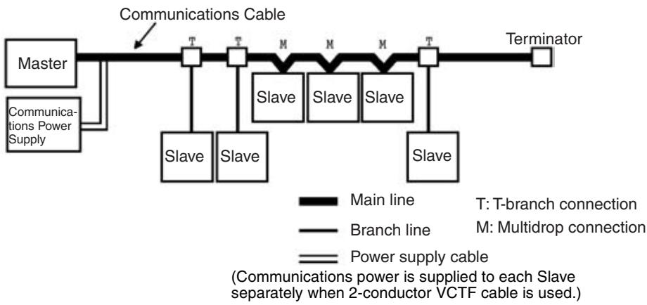
- The main line is the cable that connects the ends of the system. The maximum length of the main line depends on the communications mode, the type of cable, and the number of Slaves being used. Refer to 2-2-2 Maximum Cable Length for details.
- A branch line is any cable that branches off the main line. The maximum length of a single branch line and the maximum total length of all branch lines in a CompoBus/S system vary according to the communications mode, the types of cables used, and the number of Slaves. Refer to 2-2-2 Maximum Cable Length for details.
- The Master must be connected at one end of the main cable and the terminator must be connected at the other end. The Master cannot be connected at a point along the main line or on a branch line.
- Only one Master can be connected in the CompoBus/S System. The range of usable node numbers that can be connected depends on the model of Master being used and its settings. Refer to 2-1 Communications Specifications for details.
- Only one Slave can be connected to each branch line. It is not possible to branch again from a branch line.
- There are three types of cable that can be used (2-conductor VCTF cable, 4-conductor VCTF, and Special Flat Cable), but it is not possible to use more than one type of cable in the same CompoBus/S System.
System with No Distinction between Main and Branch Lines
The following diagram shows a CompoBus/S System configuration in which no distinction is required between the main line and the branch lines under either of the following conditions.
- The system operates in Long-distance Communications Mode with 4-conductor VCTF cable
- The system operates in Long-distance Communications Mode with Special Flat Cable
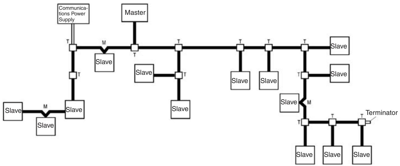

Communications cable
Power supply cable
T: T-branch connection
M: Multidrop connection
- When the system operates in Long-distance Communications Mode with Special Flat Cable or 4-conductor VCTF cable used, there will be no need to distinguish main and branch lines for the system. It is not, however, possible to use more than one type of cable in the same CompoBus/S system.
- The maximum length of cable used for the CompoBus/S system is 200 m regardless of the type of communications cable.
- Only a single terminator farthest from the Master is required regardless of the position the Master is connected to the communications cable.
- More than a single Master cannot be connected to the CompoBus/S System. The possible range of node numbers varies with the type of Master and settings in the Master. Refer to 2-1 Communications Specifications Specifications for details.
Connection Methods
The Master and Slaves can be connected by either the T-branch method or the multidrop method.
T-branch Method
In the T-branch method, a branch connector, a commercially available terminal block, or a T-joint is used to create a branch from the main line and connect a Slave when the main line is distinguished from branch lines. The maximum length of the branch line varies according to the communications mode and the type of cable used. For details, refer to 2-2-2 Maximum Cable Length. A secondary branch cannot be connected to the branch line when the main line is distinguished from branch lines.
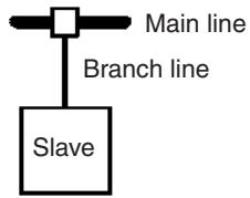
System with Distinction between Main and Branch Lines
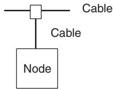
System with No Distinction between Main and Branch Lines
The actual wiring for T-branch connections is given next.
1,2,3... 1. Branch Connector
When using Special Flat Cable, connect a Branch Connector to the main line to create a branch, as shown in the following diagram.
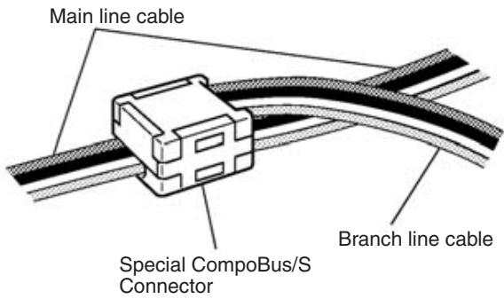
2. Terminal Block Connector
A commercially available relay terminal block (a terminal block in which the opposite terminals are connected) can be used to create a branch line, as shown in the following diagram.
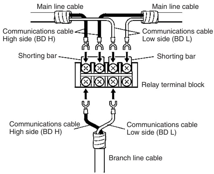
3. T-joint
When 4-conductor VCTF cable is used, use a T-joint to branch the line as shown below.

Multidrop Method
In the multidrop method, nodes are connected directly to the cable. It is not necessary to create a new branch line or use special connectors with the mul
tidrop method. When the main line is distinguished from branch lines, Slaves must be connected to the main line.
System with Distinction between Main and Branch Lines
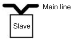
System with No Distinction between Main and Branch Lines
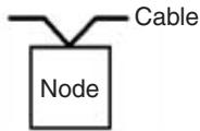
The actual wiring for multidrop connections is shown in the following diagram. The Slave is connected to the signal wires from the Master side of the system as well as the signal wires from the terminator side of the system.
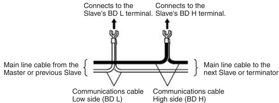
2-2-2 Maximum Cable Length
The main line length is the total length of the cable connecting the Master and the terminator at the farthest end of the system. The branch line length is the length of a cable connecting a Slave to the main line and the total branch line length is the sum of lengths of all of the branch lines in the system.
When the system has no main line distinguished from the branch lines, the communications cable can be connected with no particular restrictions, provided that the total length of communications cable is a maximum of 200m .
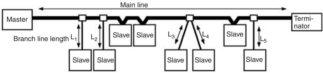
Total branch line length = L_1 + L_2 + L_3 + L_4 + L_5
The maximum main line, branch line, total branch line, and total cable lengths depend on the type of cable and number of Slaves being used, as shown in the following table.
| Communication mode | Cable type | Cable length | ||
| Main line | Branch line | Total of branch lines | ||
| High-speed Communications Mode | 2-conductor VCTF cable | 100 m max. | 3 m max. | 50 m max. |
| 4-conductor VCTF cable | 30 m max. (See note.) | 3 m max. | 30 m max. (See note.) | |
| Flat | 30 m max. (See note.) | 3 m max. | 30 m max. (See note.) | |
| Long-distance Communications Mode | 2-conductor VCTF cable | 500 m max. | 6 m max. | 120 m max. |
| 4-conductor VCTF cable | Total length of communications cable: 200 m max. (with no distinction between main and branch lines) | |||
| Flat | Total length of communications cable: 200 m max. (with no distinction between main and branch lines) | |||
Note If the number of connected Slaves does not exceed 16 when using the High-speed Communications Mode, the main line length can be up to 100m and the total branch line length can be up to 50m (i.e., the same as for the VCTF cable). An example is given below.
Refer to the following examples.
Example 1
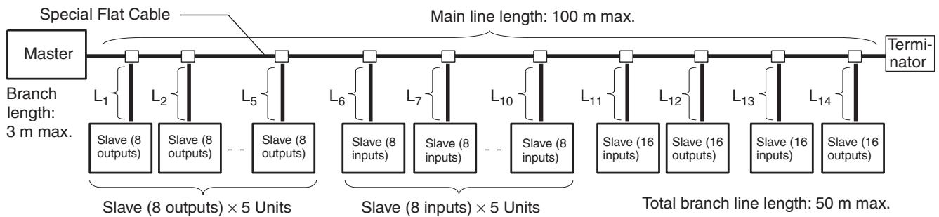
| No. of Slave Units | 8-input Slave × 5 Units + 8-output Slave × 5 Units + 16-input Slave × 2 Units + 16-output Slave × 2 Units = 14 Slave Units |
| Number of I/O points | 72 inputs and 72 outputs |
Example 2

| No. of Slave Units | 16-input Slave × 8 Units + 16-output Slave × 8 Units = 16 Slave Units |
| Number of I/O points | 128 inputs and 128 outputs |
Do not mix 2-conductor VCTF, 4-conductor VCTF, and Special Flat Cables in the same system.
Refer to the Appendix Standard Models for details on compatible communications cables.
Note When 4-conductor VCTF or Special Flat Cable is used to supply the Slave's communications power, the length of the cable may be limited by current and voltage drops in the cable and connectors. Refer to 2-3-3 Limitations of Communications Cable Power Supply on page 35 for details.
2-2-3 Terminator Connection
System with Distinction between Main and Branch Lines
A terminator must be connected to the end of the main line opposite the Master (the farthest end of the cable) in order to stabilize communications. When the last Slave in the system is connected to the main line by a T-branch connector, make sure that the terminator is farther from that T-connection than the Slave so that the terminator is farther from the Master.
The following diagram shows the connections in a typical CompoBus/S System with distinguished main and branch lines. The power supply system has been omitted.
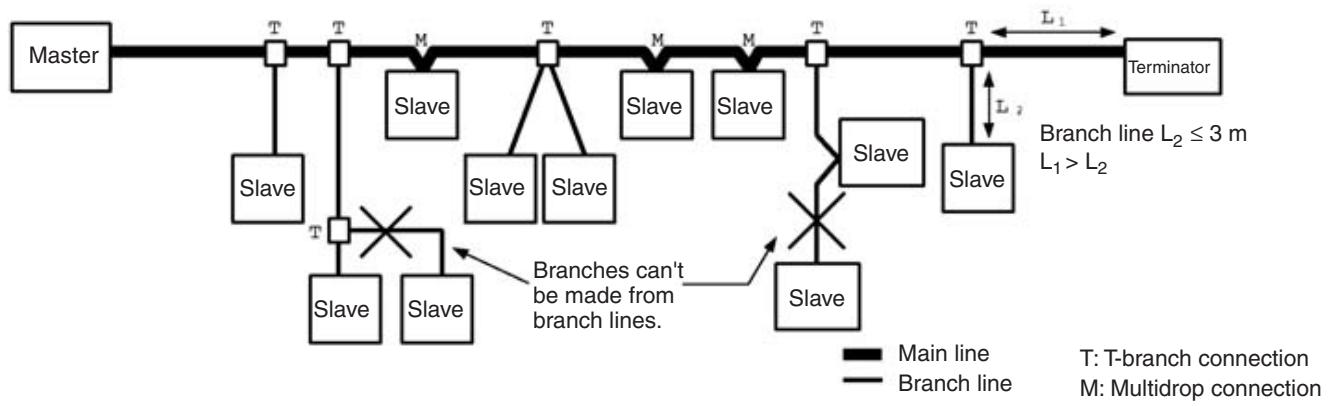
System with No Distinction between Main and Branch Lines
A terminator must be connected to the end of the communications cable farthest from the Master in order to stabilize communications. When the last Slave in the system is connected to the communications cable by a T-branch connector, extend the cable to connect the terminator or connect the terminator at the T-branching position. The cable distance to the terminator includes the total cable length.
2-3 Supplying Power to the Slaves
The Slaves must be supplied with power for communications and some Slaves must have a separate power supply for I/O. The methods for supplying power to the Slaves depend on the type of communications cable being used.
| Slave power supply | Usage | 2-conductor VCTF cable | 4-conductor VCTF cable Special Flat Cable | |
| Network power supply | 1 | For both communications and I/O | External power supply (collective supply possible) | Power supplied via 4-conductor VCTF cable, Special Flat Cable, or from external power source |
| Multiple power supply | 2 | For communications | External power supply (collective supply possible) | Power supplied via 4-conductor VCTF cable, Special Flat Cable, or from external power source |
| For I/O | External power supply (collective supply impossible) | External power source | ||
| Local power supply | 1 | For both communications and I/O | External power supply (collective supply impossible) | External power source |
The following table groups the Slaves according to their power supply requirements.
| Power supply | Slave type | Model numbers |
| Network power supply | Sensor Terminals | SRT1/SRT2-ID08S SRT1/SRT2-ND08S |
| Fiber Amplifier Communications Unit | E3X-SRT21 | |
| Analog I/O Terminals | SRT2-AD04 SRT2-DA02 | |
| Multiple power supplies | Remote Terminals with Transistors | SRT1/SRT2-ID04 SRT1/SRT2-ID04-1 SRT1/SRT2-ID08 SRT1/SRT2-ID08-1 SRT1/SRT2-ID16 SRT1/SRT2-ID16-1 SRT1/SRT2-OD04 SRT1/SRT2-OD04-1 SRT1/SRT2-OD08 SRT1/SRT2-OD08-1 SRT1/SRT2-OD16 SRT1/SRT2-OD16-1 |
| Connector Terminals with Transistors | SRT2-VID08S SRT2-VID08S-1 SRT2-VID16ML SRT2-VID16ML-1 SRT2-VID32ML SRT2-VID32ML-1 SRT2-VOD08S SRT2-VOD08S-1 SRT2-VOD16ML SRT2-VOD16ML-1 | |
| Water-resistant Terminals with Transistors | SRT2-ID04CL SRT2-ID04CL-1 SRT2-ID08CL SRT2-ID08CL-1 SRT2-OD08CL-1 | |
| Local power supply | Sensor Terminals with Connector Outputs | SRT1/SRT2-OD08S |
| Remote Terminals with Relays | SRT1/SRT2-ROC08 SRT1/SRT2-ROC16 | |
| Remote Terminals with Power MOS FETs | SRT1/SRT2-ROF08 SRT1/SRT2-ROF16 | |
| --- | Remote I/O Modules | SRT1/SRT2-ID16P SRT1/SRT2-OD16P |
| --- | CPM1A/CPM2A I/O Link Unit | CPM1A-SRT21 |
| --- | CPM2C I/O Link Unit | CPM2C-SRT21 |
Communications Power Supply
OMRON's S82-series Power Supplies are recommended for supplying power to the Slaves for communications. Select a power supply with a current capacity greater than the total power consumed by all of the Slaves that will be connected.
Note Be sure to provide a power supply with a current capacity sufficient to handle the surge current that flows at startup.
2-3-1 Using 2-conductor VCTF Cable
Power cannot be supplied to the Slaves through 2-conductor VCTF cable. When a CompoBus/S System is being constructed with 2-conductor VCTF cable, each Slave must be supplied with power along a route separated from the VCTF cable. Furthermore, an I/O power supply must be provided for Slaves that require an I/O power supply.
Independent Power Supplies

Note Both T-branch connections and multidrop connections are possible with each type of power supply.
Common Power Supply
When using a common power supply with long power lines, make sure that there isn't a significant decline in the supply voltage due to attenuation.
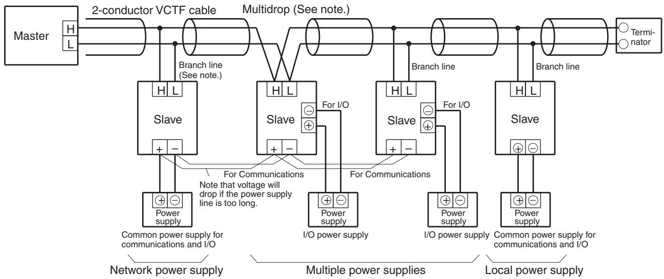
Note Both T-branch connections and multidrop connections are possible with each type of power supply.
It is possible to supply all communications power collectively via a single line. If the power supply line is too long, however, the conductor resistance of the cable will cause voltage to drop. For information concerning the allowable length of the collective power supply cable, refer to 4. Cable Length Limit Due
to Voltage Drop in 2-3-3 Limitations of Communications Cable Power Supply on page 37. In this case, replace the figure stated for the cable's resistance with the conductor resistance of the collective communications power supply cable in your calculations to verify the allowable cable length.
Note
Depending on the loads connected, multiple power supplies for I/O may generate electrical noise. Even for a collective power supply, the I/O power supply should be separated from the communications power supply so that it does not affect other Slaves. Similarly, a local power supply used for both communications and I/O should also be kept separate from communications power supplies.
2-3-2 Using 4-conductor VCTF or Special Flat Cable
Power can be supplied to the Slaves through 4-conductor VCTF or Special Flat Cable. When a CompoBus/S System is being constructed with 4-conductor VCTF or Special Flat Cable, the method used to supply power to the Slaves depends on the type of Slave being used.
The following diagram shows an example of a CompoBus/S System connected with Special Flat Cable that uses each type of Slave. There is no difference in configuration when 4-conductor VCTF cable is used.
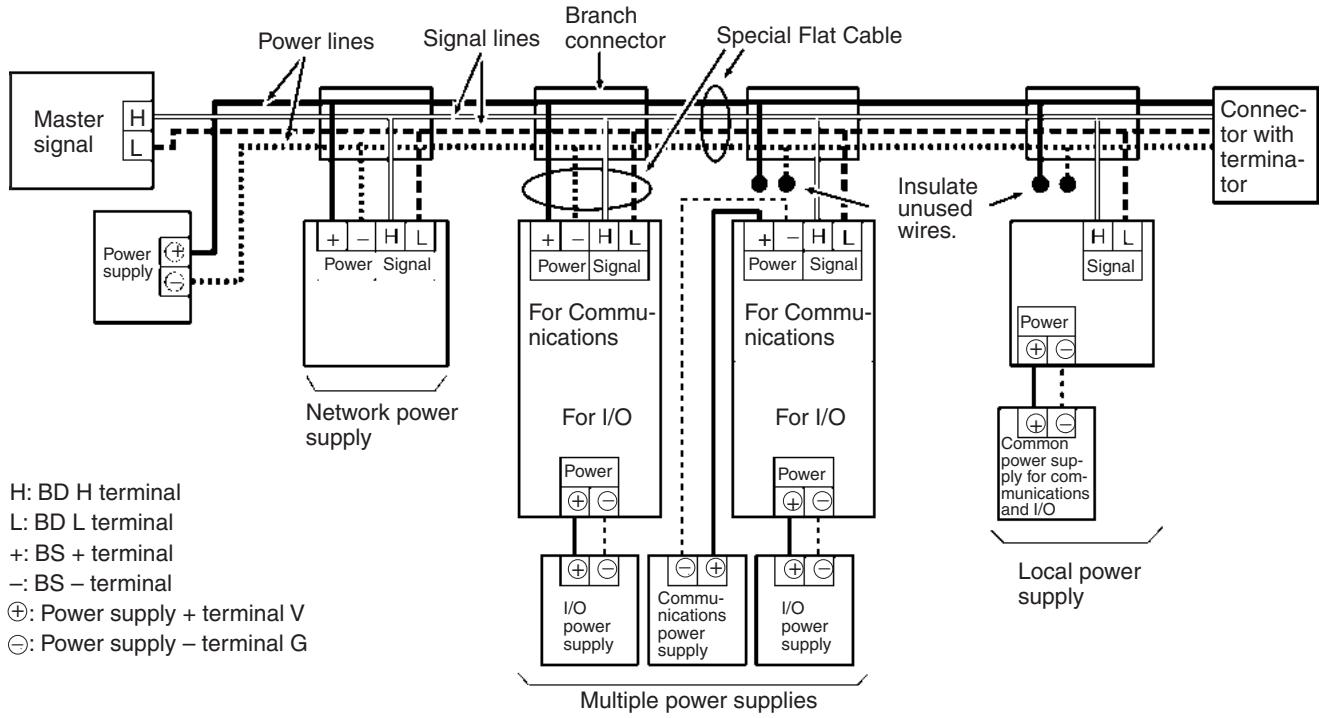
Note
-
Be sure to insulate unused Special Flat Cable wiring when using a Slave that requires a local power supply or using an external power supply for communications in a Slave that requires multiple power supplies.
-
If multiple CompoBus/S Systems are used, provide a separate communications power supply for each CompoBus/S System to prevent unstable operation due to unwanted noise paths in the power supplies of the CompoBus/S Systems.
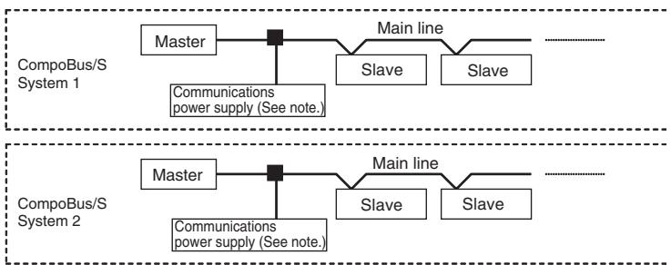
Note: Use a separate communications power supply for each line.
- When using CJ-series Master Units, use 6-pin communications connectors that allow simultaneous connection of communications and power supply cables. Power can be supplied to the Slaves easily by connecting the communications power supply to the Master Unit without preparing the communications cables, as shown in the following diagram.
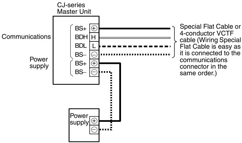
The BS + and BS- terminals of the CJ-series Master Unit's communications connector are connected internally. (The Master Unit does not use the BS + or BS- terminals.)
2-3-3 Limitations of Communications Cable Power Supply
Check the following points when using 4-conductor VCTF or Special Flat Cable to supply power to Slaves.
- The 4-conductor VCTF or Special Flat Cable's allowable current
- The Extension Connector's allowable current (when using an Extension Connector)
- The allowable current of the CJ-series Master Unit's communications connector (when using CJ-series Master Units)
- Cable length limit due to voltage drop
1. 4-conductor VCTF or Special Flat Cable's Allowable Current
The allowable current through the 4-conductor VCTF or Special Flat Cable depends on the ambient temperature, as shown in the following tables.
4-conductor VCTF Cables
| Ambient temperature (°C) | 0 | 5 | 10 | 15 | 20 | 25 | 30 | 35 | 40 | 45 |
| Allowable current (A) | 7 | 7 | 7 | 7 | 7 | 7 | 7 | 6 | 5.5 | 4.5 |
- Special Flat Cables
| Ambient temperature (°C) | 0 | 5 | 10 | 15 | 20 | 25 | 30 | 35 | 40 | 45 |
| Allowable current (A) | 13 | 12 | 11 | 10 | 8 | 7 | 6 | 5 | 4 | 3 |
The total current supplied to the Slaves must be less than the allowable current, regardless of whether the system has a main line distinguished from the branch lines or not.
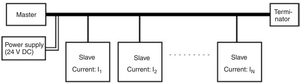
For example, at 30^ the total current consumption of the Slaves must be 6 A or less when Special Flat Cable is used.
2. Extension Connector or T-joint's Allowable Current
The allowable current through an Extension Connector is 4 A and that through a T-joint is 3 A. Therefore, the total current supplied to the Slaves beyond the Extension Connector or T-joint must be less than 4 A, regardless of whether the system has a main line distinguished from the branch lines or not.
Extension Connector
$$ \left. \left. I _ {1} + I _ {2} + \dots + I _ {N} \leq 4 A \right. \right. $$
(I_1,I_2,I_N : current consumption of each Slave after Extension Connector)
T-joint
$$ I _ {1} + I _ {2} + \dots + I _ {N} \leq 3 A $$
(I_1, I_2, I_N) : current consumption of each Slave after the T-joint.
Example
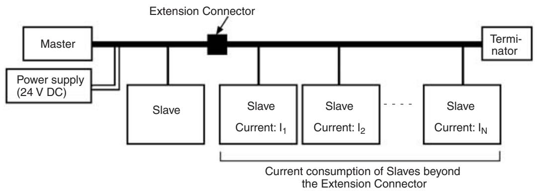
Extension Connector used
Note When a commercially available terminal block is used, be sure the current consumption is within the allowable current of the block.
3. Allowable Current for CJ-series Communications Connector
The allowable current for the communications connector of the CJ-series Master Unit is 4 A. The total current consumption of Slaves must be no more than 4 A when the CJ-series Master Unit communications connector is connected to the communications power supply. (The same applies when there is no distinction between main and branch lines.)
$$ \left. \left. I _ {1} + I _ {2} + \dots + I _ {N} \leq 4 A \right. \right. $$
(I_1, I_2, , I_N) represents the current consumption of each Slave being supplied with communications power supply.)
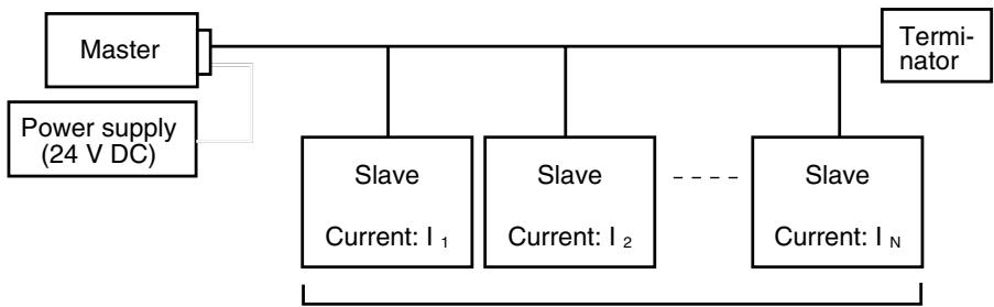
Current consumption of Slaves being supplied with communications power supply.
4. Cable Length Limit Due to Voltage Drop
The voltage drop can be calculated from the cable's length, the cable's resistance, and the Slave's current consumption. (The cable's length is multiplied by 2 because there are two wires carrying current, + and -.)
Voltage drop (V) = Current (A) × (Cable's length × 2 × Cable's resistance) (Ω)
The allowable voltage range for the Slaves is 14 to 26.4V DC, so the maximum voltage drop is 10V DC when using a 24-V DC power supply.
The equation yielding the voltage drop for the following system is shown below. This is an approximate equation allowing some margin for error.

$$ 1 0 \geq \left(I _ {1} + I _ {2} + \dots + I _ {N}\right) \times L \times 2 \times R $$
10: Max. voltage drop (V)
R: Resistance of the Special Flat Cable ( /m)
4-conductor VCTF cable: 0.025
Special Flat Cable: 0.027
L_1 + L_2 + + L_N : Length of cable between the Slaves
The maximum cable length (L) can be calculated from this equation as follows:
$$ \begin{array}{c} L \leq 1 0 / \left{\left(I _ {1} + I _ {2} + \ldots + I _ {N}\right) \times 2 \times R \right} \ \downarrow \end{array} $$
L ≤ 200 / (I1 + I2 + + I_N) 4-conductor VCTF cable
185 / (I_1 + I_2 + + I_N) ... Special Flat Cable
L is the length of cable to the last Slave (L_1 + L_2 + +L_N)
I_1 + I_2 + + I_N : Current consumption of each Slave (A)
Note
- The allowable voltage range for a Sensor Terminal which has a 2-wired method Proximity Switch connected is 20.4 to 26.4 V DC. If the Special Flat Cable's voltage is below 20.4 V DC, use an external power supply for the Sensor Terminal.
- When there is no distinction between main and branch lines, substitute the cable length between the communications power supply and the farthest end for L in the above formula. If the communications power supply is at the midway point in the cable path, the cable length on the left-hand side added with that on the right-hand side will be the maximum length of the communications cable. If only some Slaves are located far from the Master, the maximum cable length calculated from the cable length to the last Slave may be very short. In such cases, calculate the voltage drop at each branching position and Slave position and design the system with an appropriate margin so that the voltage applied to each Slave will be high enough.
Example
Communications cable: Special Flat Cable
In this example a single power supply can't provide power to all of the Slaves, so the Slaves are divided into 2 groups and supplied by 2 power supplies.
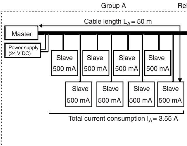
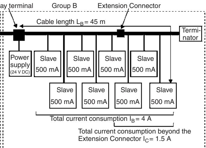
Check that each group meets the current consumption conditions. In this case the ambient temperature is 30^ .
- Group A
Special Flat Cable's Allowable Current:6 A ≥ 3.55 A (IA)
Cable Length Limit due to Voltage Drop: 185 / 3.55 = 52m≥ 50m(L_A)
- Group B
Special Flat Cable's Allowable Current:6 A ≥ 4 A (IB)
Extension Connector's Allowable Current: 4.5 A ≥ 1.5 A (Ic)
Cable Length Limit due to Voltage Drop: 185 / 4 = 46m≥ 45m(L_B)
When dividing the Slaves into groups to supply power, connect the groups using a standard relay terminal like the one shown in the following diagram.
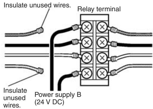
Communications power + (BS ^+ , brown) Communications data high (BD H, black) Communications data low (BD L, white) Communications power - (BS -, blue)
Voltage Drops Due to Wiring
When components such as circuit protectors, contactors, connectors, and fuses are incorporated in the wiring, the internal resistance and contact resistance of these components can have an effect on voltage drops as well as the conductor resistance of the cable itself. When designing the wiring, attention must be paid to these resistance values as well.
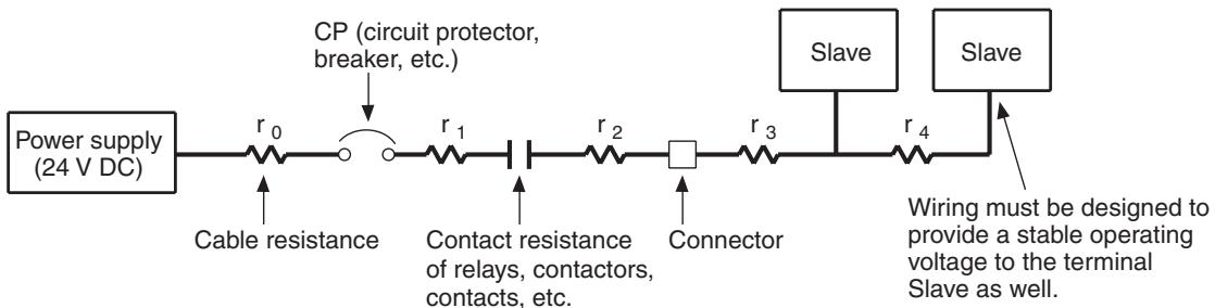
Note The resistance and allowable current varies according to the cross section, material, and structure of the cable, as well as the ambient temperature. When designing the wiring and selecting the cables to be used, refer to the specifications stated by the cable manufacturer.
Arrangement of Power Supplies
In systems in which the I/O power supply for the entire system is supplied, it is necessary to take into account the power consumption of each device and load. Cables selected for use with the terminal Slave or load should also keep voltage fluctuations within the allowable range. Care must also be taken to ensure that the total current on the lines is within the range of the permissible current of the cable, and that the capacity of the power supply is adequate.
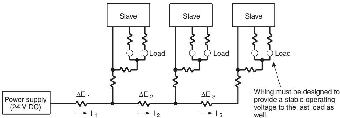
Examine the following points when deciding whether to supply I/O power for the entire system from a single source, or to install multiple power supplies.
1,2,3... 1. Supplying I/O Power for Slaves from Multiple Power Supplies
Supplying I/O power from several sources rather than from a single source enables line current to be reduced, and reduces voltage drops.
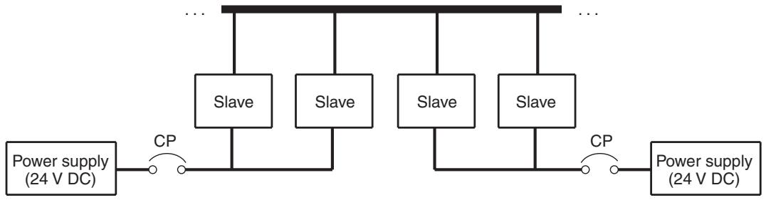
2. Supplying Power from Single Unit
Use the following methods for keeping voltage drops within allowable range when power is supplied from a single source.
- Increase cable thickness.
- Raise output voltage of power supply slightly.
- Shorten wiring distances.
3. Considerations Relating to Power Supply Malfunctions
It is necessary to examine system operation in the event of a power supply malfunction.
Example:
a) Design the system to halt operation of all loads in the event of a single power supply failure.
b) Design the system to prevent all loads stopping operation by installing more than one power supply.
4. Cost Considerations
It is also necessary to examine the costs associated with I/O power supply installation, such as the number of power supplies, cable thickness, cable length, and the labor required.
2-4 System Configuration Using Water-resistant Terminals
Use 4-conductor VCTF cable for communications when Water-resistant Terminals are used.
Wire the cables as shown below regardless of whether the system has a main line distinguished from the branch lines or not.
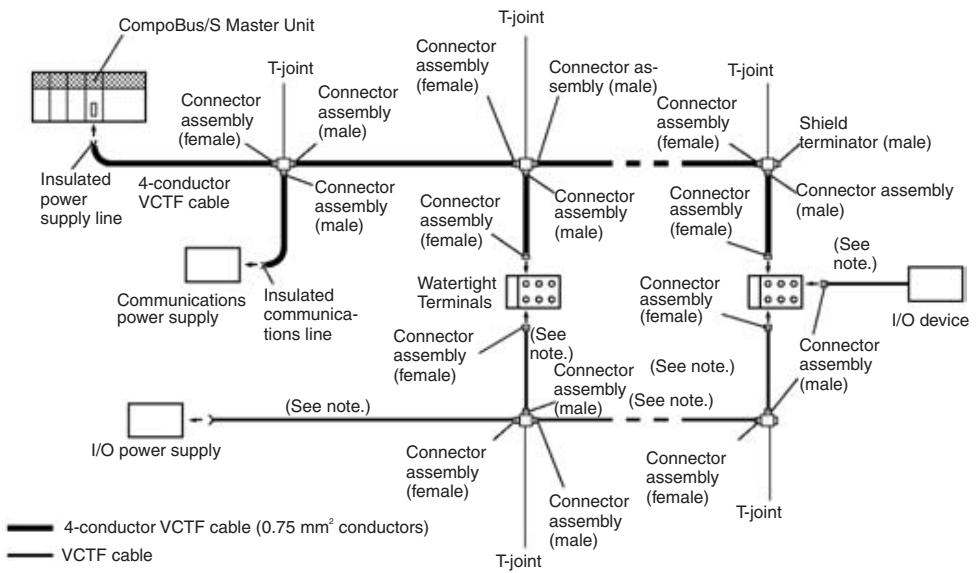
Note Use VCTF cable for the external power supply. OMRON's Connectors with Cables can be used as well.
To connect Slaves other than the Water-resistant Terminals, use communications cable with no connectors and wire the cable with crimp terminals. If the cable requires water resistance, use a commercially available terminal block instead of T-joints.
Note When using 4-conductor VCTF Connector with Cable Assemblies, use one of the following combinations of cable conductor colors and signals for stable communications.
| Conductor color | Signal | |||
| Pattern 1 | Pattern 2 | Pattern 3 | Pattern 4 | |
| White | BD H | BS + | BS - | BD L |
| Red | BS + | BS - | BD L | BD H |
| Green | BS - | BD L | BD H | BS + |
| Black | BD L | BD H | BS + | BS - |
2-5 I/O Response Time Characteristics
This section explains the minimum and maximum I/O response times of the CompoBus/S System. Use this section for reference when planning operations that require precise I/O timing.
The I/O response time is the time it takes from the reception of an input signal at a CompoBus/S Input Slave to the output of the corresponding output signal at a CompoBus/S Output Slave.
The information provided here, however, is only for when a Communications Unit is used as the Master Unit. For details on using the SRM1 Master Control Unit and CPM2C-S Series, refer to the CompoBus/S SRM1 Master Control Units Operation Manual (W318) or CPM2C-S PLC Operation Manual (W377).
2-5-1 Slaves Other Than Analog Terminals
The following timing chart shows the minimum I/O response time.
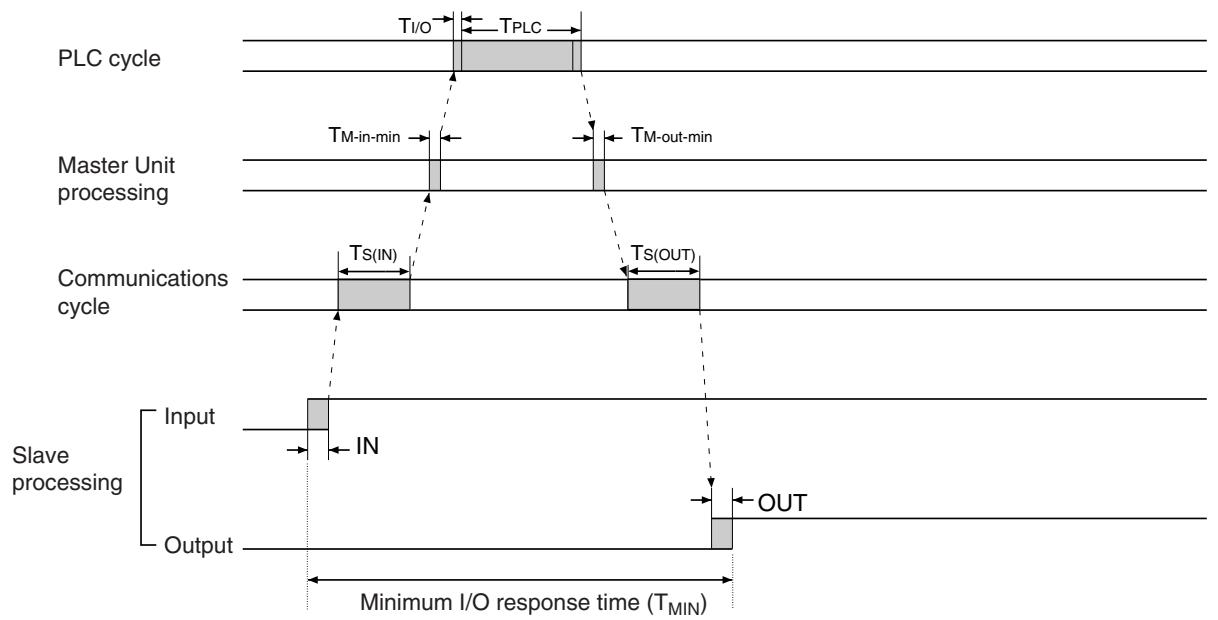
Minimum I/O Response Time
The minimum I/O response time is the total of the following terms:
$$ T _ {\text {M I N}} = \mathrm {I N} + T _ {\mathrm {S} (\mathrm {I N})} + T _ {\mathrm {M - i n - m i n}} + T _ {\mathrm {I} / \mathrm {O}} + T _ {\mathrm {P L C}} + T _ {\mathrm {M - o u t - m i n}} + T _ {\mathrm {S} (\mathrm {O U T})} + \mathrm {O U T} $$
T_MIN : Minimum I/O response time
TPLC: PLC's cycle time
IN: Input delay in the Slave (Refer to 2-5-3 Slave I/O Delay Times on page 51.)
OUT: Output delay in the Slave (Refer to 2-5-3 Slave I/O Delay Times on page 51.)
T_S(IN) : Input data transmission time for one node.
High-speed Communications Mode: 20~ s
Long-distance Communications Mode: 160~ s
T_M-in-min : Minimum input processing time in the Master
CS-series, C200HX/HG/HE-(Z)E, C200HS, or CQM1 Master Unit:
T_M - in - min = 0 s
CS-series Master Units:
T_M-in - min = 20 s (allocated words for 1 unit number),
25 μs (allocated words for 2 unit numbers)
CJ-series Master Units:
T_M-in-min = 25 s
T_M-out-min : Minimum output processing time in the Master
CS-series, C200HX/HG/HE-(Z)E, C200HS, of CQM1 Master Unit:
T_M - out - min = 0 s
CS-series Master Units:
T_M-out - min = 33~ s (allocated words for 1 unit number),
43.5 μs (allocated words for 2 unit numbers)
CJ-series Master Unit:
T_M - out - min = 45~ s
T_S(OUT) : Output data transmission time for one node.
High-speed Communications Mode: 15~ s
T_I / O
Long-distance Communications Mode: 110~ s
I/O refreshing time
CS-series, C200HX/C200HG/C200HE-(Z)E, and C200HS Master Units
| PLC | Usable node number setting | |
| IN0 to IN7 and OUT0 to OUT7 | IN0 to IN15 and OUT0 to OUT15 | |
| CS Series, and C200HX/ C200HG/ C200HE-(Z)E | T1/O = 440 μs | T1/O = 880 μs |
| C200HS | T1/O = 1,000 μs | T1/O = 2,000 μs |
CS-series Master Units
| PLC | Usable node number setting | |
| IN0 to IN7 and OUT0 to OUT7 | IN0 to IN15 and OUT0 to OUT15 | |
| CS1 (without -H suffix) | T1/O = 160 μs | T1/O = 180 μs |
| CS1-H | T1/O = 120 μs | T1/O = 130 μs |
Note
- The values in the above table are applicable when connected to the CPU Rack. Add another 20~ s to the values shown in the table when connecting to an Expansion Rack.
- Add another 20~ s to the values shown in the table when using the Slave registration function or communications stop mode.
CJ-series Master Units
| PLC | Usable node number setting | |
| IN0 to IN7 and OUT0 to OUT7 | IN0 to IN15 and OUT0 to OUT15 | |
| CJ1 (without -H suffix) | T1/O = 160 μs | T1/O = 180 μs |
| CJ1-H | T1/O = 120 μs | T1/O = 130 μs |
Note
- The values in the above table are applicable when connected to the CPU Rack. Add another 20~ s to the values shown in the table when connecting to an Expansion Rack.
- Add another 20~ s to the values shown in the table when using the Slave registration function or communications stop mode.
CQM1 Master Units
| PLC | PLC word allocation setting | ||
| 2 words | 4 words | 8 words | |
| CQM1 | T_I/O = 15 μs | T_I/O = 30 μs | T_I/O = 60 μs |
Maximum I/O Response Time
The following timing chart shows the maximum I/O response time.
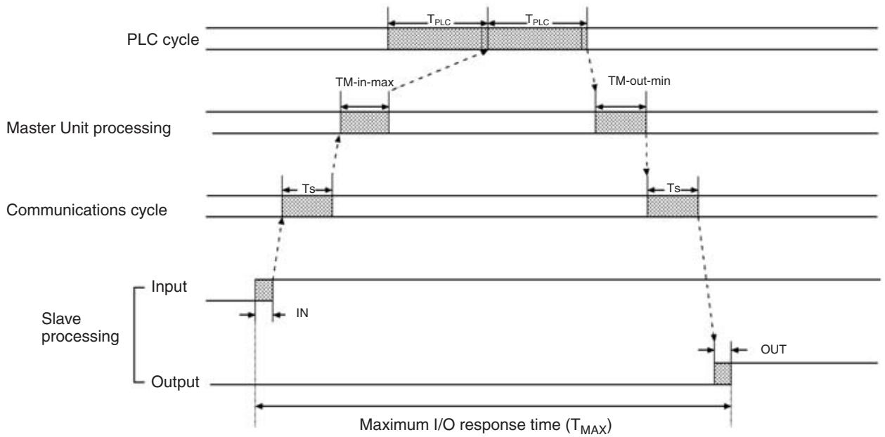
The maximum I/O response time is the total of the following terms:
$$ T _ {M A X} = I N + T _ {S} + T _ {M - i n - m a x} + T _ {P L C} \times 2 + T _ {M - o u t - m a x} + T _ {S} + O U T $$
T_ MAX : Maximum I/O response time
TPLC: PLC's cycle time
IN: Input delay in the Slave (Refer to 2-5-3 Slave I/O Delay Times on page 51.)
OUT: Output delay in the Slave (Refer to 2-5-3 Slave I/O Delay Times on page 51.)
TS: Communications cycle time
| Master | Usable node number setting | Communications cycle time | |
| High-speed Communica-tions Mode | Long-distance Communica-tions Mode | ||
| CS-series, C200HX/C200HG/C200HE-(Z)E, and C200HS Master Unit, CS-series Master Unit, or CJ-series Master Unit | IN0 to IN7 and OUT0 to OUT7 | 500 μs | 4,000 μs |
| IN0 to IN15 and OUT0 to OUT15 | 800 μs | 6,000 μs | |
| CQM1 | IN0 to IN1 and OUT0 to OUT1 | 500 μs | 4,000 μs |
| IN0 to IN3 and OUT0 to OUT3 | |||
| IN0 to IN7 and OUT0 to OUT7 | |||
| IN0 to IN15 and OUT0 to OUT15 | 800 μs | 6,000 μs | |
T_M-in - max : Maximum input processing time in the Master
CS-series, C200HX/C200HG/C200HE-(Z)E, and C200HS Master Units
| Master | Number of points/ node number | Max. input pro-cessing time |
| CS Series, C200HX/ C200HG/ C200HE-(Z)E, and C200HS | --- | 470 μs |
CS-series Master Units
| Master | Usable node number setting | |
| IN0 to IN7 and OUT0 to OUT7 | IN0 to IN15 and OUT0 to OUT15 | |
| CS1 (without -H suffix) | TM-in-max = 270 μs | TM-in-max = 320 μs |
| CS1-H | TM-in-max = 220 μs | TM-in-max = 270 μs |
Note Add another 15~ s to the values in the table when using the Slave registration function or communications stop mode.
CJ-series Master Units
| Master | Usable node number setting | |
| IN0 to IN7 and OUT0 to OUT7 | IN0 to IN15 and OUT0 to OUT15 | |
| CJ1 (without -H suffix) | TM-in-max = 270 μs | TM-in-max = 320 μs |
| CJ1-H | TM-in-max = 220 μs | TM-in-max = 270 μs |
Note Add another 15~ s to the values in the table when using the Slave registration function or communications stop mode.
CQM1 Master Units
| Master | Number of points/node number | Max. input processing time |
| CQM1 | 8-point mode | 300 μs |
| 4-point mode | 860 μs |
T_M-out - max :Maximum output processing time in the Master
CS-series, C200HX/C200HG/C200HE-(Z)E, and C200HS Master Units
| Master | Number of points/ node number | Max. output pro-cessing time |
| CS-series, C200HX/ C200HG/ C200HE-(Z)E, and C200HS Masters | --- | 650 μs |
CS-series Master Units
| Master | Usable node number setting | |
| IN0 to IN7 and OUT0 to OUT7 | IN0 to IN15 and OUT0 to OUT15 | |
| CS1 | TM-out-max = 100 μs | TM-out-max = 130 μs |
Note Add another 15~ s to the values in the table when using the Slave registration function or communications stop mode.
CJ-series Master Units
| Master | Usable node number setting | |
| IN0 to IN7 and OUT0 to OUT7 | IN0 to IN15 and OUT0 to OUT15 | |
| CJ1 | TM-out-max = 100 μs | TM-out-max = 130 μs |
Note Add another 15~ s to the values in the table when using the Slave registration function or communications stop mode.
CQM1 Master Units
| Master | Number of points/node number | Max. output processing time |
| CQM1 | 8-point mode | 480 μs |
| 4-point mode | 1,040 μs |
Recognition of Slave I/O Status at Startup
When the CompoBus/S System is turned ON, the I/O of Slaves connected to CQM1 Masters may not become effective at the same time as the I/O of Slaves connected to CS-series, CJ-series, C200HX/C200HG/C200HE-(Z)E, and C200HS Masters.
CS-series, CJ-series, C200HX/C200HG/C200HE-(Z)E, and C200HS Masters
The I/O of a Slave connected to a CS-series, C200HX/C200HG/C200HE-(Z)E, C200HS, or CJ-series Master becomes effective when the Active Node Flag for the Slave goes ON.
CQM1 Masters
The I/O of a Slave connected to a CQM1 Master becomes effective some time after the Master's PLC is turned ON.
In High-speed Communications Mode: (PLC cycle time) + 118 ms
In Long-distance Communications Mode: (PLC cycle time) + 720 ms.
2-5-2 Slave Analog Terminals
The following timing chart shows the minimum I/O response time.
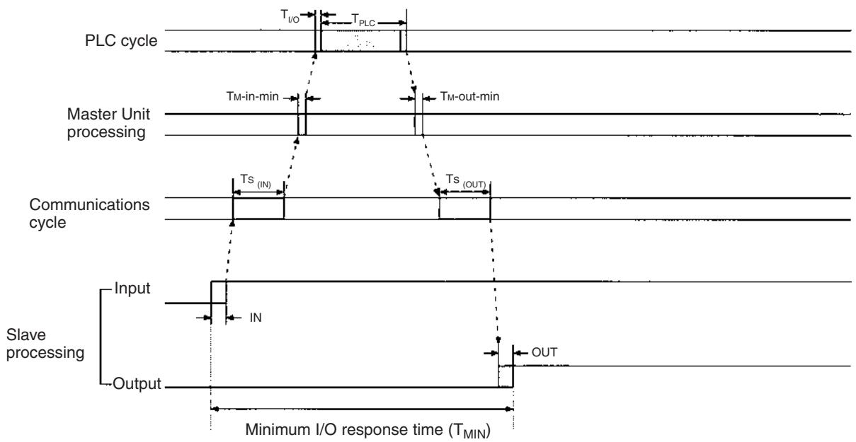
Minimum I/O Response Time
The minimum I/O response time is the total of the following terms:
$$ T _ {\text {M I N}} = \mathrm {I N} + T _ {\mathrm {S} (\mathrm {I N})} + T _ {\mathrm {M - i n - m i n}} + T _ {\mathrm {I O}} + T _ {\mathrm {P L C}} + T _ {\mathrm {M - o u t - m i n}} + T _ {\mathrm {S} (\mathrm {O U T})} + \mathrm {O U T} $$
T_MIN : Minimum I/O response time
TPLC: PLC's cycle time
Ts (IN): Input data transmission time for one node
High-speed Communications Mode: 20~ s
Long-distance Communications Mode: 160~ s
T_M-in-min :Input processing time in the Master
| Master | Input processing time |
| CS Series, C200HX/C200HG/ C200HE-(Z)E, and C200HS | 160 μs |
| CS Series | 20 μs (allocated words for 1 unit number), 25 μs (allocated words for 2 unit numbers) |
| CJ Series | 25 μs |
| CQM1 | 120 μs |
T_M-out-min : Minimum output processing time in the Master
| Master | Min. input processing time |
| CS Series, C200HX/C200HG/ C200HE-(Z)E, and C200HS | 35 μs |
| CS Series | 35 μs (allocated words for 1 unit number), 45 μs (allocated words for 2 unit numbers) |
| CJ Series | 45 μs |
| CQM1 | 40 μs |
TS (OUT): Output data transmission time for one node
High-speed Communications Mode: 15~ s
Long-distance Communications Mode: 110~ s
IN: Input delay in the Slave (Minimum value is 0.)
OUT: Output delay in the Slave (Minimum value is 0.)
T_1 / 0 : I/O refreshing time
CS-series, C200HX/C200HG/C200HE-(Z)E, and C200HS Master Units
| Master | Usable node number setting | |
| IN0 to IN7 and OUT0 to OUT7 | IN0 to IN15 and OUT0 to OUT15 | |
| CS Series, C200HX/ C200HG/ C200HE-(Z)E | T1/O = 440 μs | T1/O = 880 μs |
| C200HS | T1/O = 1,000 μs | T1/O = 2,000 μs |
CS-series Master Units
| Master | Usable node number setting | |
| IN0 to IN7 and OUT0 to OUT7 | IN0 to IN15 and OUT0 to OUT15 | |
| CS1 (without -H suffix) | T1/O = 160 μs | T1/O = 180 μs |
| CS1-H | T1/O = 120 μs | T1/O = 130 μs |
Note 1. The values in the above table are applicable when connected to the CPU Rack. Add another 20~ s to the values shown in the table when connected to an Expansion Rack.
- Add another 20~ s to the values shown in the table when using the Slave registration function or communications stop mode.
CJ-series Master Units
| Master | Usable node number setting | |
| IN0 to IN7 and OUT0 to OUT7 | IN0 to IN15 and OUT0 to OUT15 | |
| CJ1 (without -H suffix) | T1/O = 160 μs | T1/O = 180 μs |
| CJ1-H | T1/O = 120 μs | T1/O = 130 μs |
Note 1. The values in the above table are applicable when connected to the CPU Rack. Add another 20~ s to the values shown in the table when connected to an Expansion Rack.
2. Add another 20~ s to the values shown in the table when using the Slave registration function or communications stop mode.
CQM1 Master Units
| Master | PLC word allocation setting | ||
| 2 words | 4 words | 8 words | |
| CQM1 | T_I/O = 15 μs | T_I/O = 30 μs | T_I/O = 60 μs |
The following timing chart shows the maximum I/O response time.
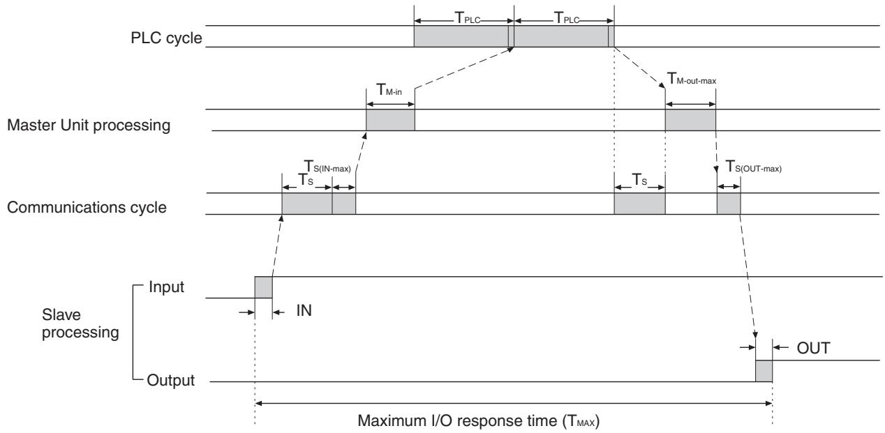
Maximum I/O Response Time
The maximum I/O response time is the total of the following terms:
$$ \begin{array}{l} T _ {M A X} = I N + T _ {S} \times 3 + T _ {M - i n} + T _ {P L C} \times 2 + T _ {M - o u t - m a x} + O U T \ \left(T _ {S} = T _ {S (I N - m a x)} + T _ {S (O U T - m a x)}\right) \ \end{array} $$
T_ MAX : Maximum I/O response time
TPLC: PLC's cycle time
IN: Input delay in the Slave (Refer to 2-5-3 Slave I/O Delay Times.)
OUT: Output delay in the Slave (Refer to 2-5-3 Slave I/O Delay Times.)
T_S Communications cycle time = Ts (IN-max) + Ts (OUT-max)
Ts (IN-max): Communications cycle input time
Ts (OUT-max): Communications cycle output time
| Master | Usable node number setting | Communications cycle time | |
| High-speed Communications Mode | Long-distance Communications Mode | ||
| CS-series, C200HX/C200HG/C200HE-(Z)E, and C200HS Master Unit, CS-series Master Unit, or CJ-series Master Unit | IN0 to IN7 and OUT0 to OUT7 | 500 μs | 4,000 μs |
| IN0 to IN15 and OUT0 to OUT15 | 800 μs | 6,000 μs | |
| CQM1 | IN0 to IN1 and OUT0 to OUT1 | 500 μs | 4,000 μs |
| IN0 to IN3 and OUT0 to OUT3 | |||
| IN0 to IN7 and OUT0 to OUT7 | |||
T_M-IN : Input processing time in the Master
| Master | Input processing time |
| CS Series, C200HX/C200HG/C200HE-(Z)E, and C200HS | 160 μs |
| CQM1 | 120 μs |
CS-series Master Units
| Usable node number setting | |
| IN0 to IN7 and OUT0 to OUT7 | IN0 to IN15 and OUT0 to OUT15 |
| TM-IN = 100 μs | TM-IN = 130 μs |
Note Add another 15~ s to the values shown in the table when using the Slave registration function or communications stop mode.
CJ-series Master Units
| Usable node number setting | |
| IN0 to IN7 and OUT0 to OUT7 | IN0 to IN15 and OUT0 to OUT15 |
| TM-IN = 100 μs | TM-IN = 130 μs |
Note Add another 15~ s to the values shown in the table when using the Slave registration function or communications stop mode.
T_M-out - max : Maximum output processing time in the Master
| Master | Max. input processing time |
| CS Series, C200HX/C200HG/C200HE-(Z)E, and C200HS | 200 μs |
| CQM1 | 230 μs |
CS-series Master Units
| Usable node number setting | |
| IN0 to IN7 and OUT0 to OUT7 | IN0 to IN15 and OUT0 to OUT15 |
| TM-out-max = 130 μs | TM-out-max = 140 μs |
Note Add another 15~ s to the values shown in the table when using the Slave registration function or communications stop mode.
CJ-series Master Units
| Usable node number setting | |
| IN0 to IN7 and OUT0 to OUT7 | IN0 to IN15 and OUT0 to OUT15 |
| TM-out-max = 130 μs | TM-out-max = 140 μs |
Note Add another 15~ s to the values shown in the table when using the Slave registration function or communications stop mode.
Recognition of Slave I/O Status at Startup
When the CompoBus/S System is turned ON, the I/O of Slaves connected to CQM1 Masters may not become effective at the same time as the I/O of Slaves connected to CS-series, CJ-series, C200HX/C200HG/C200HE-(Z)E, and C200HS Masters.
CS-series, CJ-series, C200HX/C200HG/C200HE-(Z)E, and C200HS Masters
The I/O of a Slave connected to a CS-series, CJ-series, C200HX/C200HG/ C200HE-(Z)E, and C200HS Master becomes effective when the Active Node Flag for the Slave goes ON.
CQM1 Masters
The I/O of a Slave connected to a CQM1 Master becomes effective some time after the Master's PLC is turned ON.
In High-speed Communications Mode: (PLC cycle time) +118 ms
In Long-distance Communications Mode: (PLC cycle time) +720 ms.
2-5-3 Slave I/O Delay Times
| Model | Specifications | Input specifications | Output specifications | ||
| ON delay time | OFF delay time | ON delay time (See note 1.) | OFF delay time (See note 2.) | ||
| SRT1-ID04(-1) | 4-point input terminal block | 1.5 ms max. | 1.5 ms max. | --- | --- |
| SRT1-ID08(-1) | 8-point input terminal block | 1.5 ms max. | 1.5 ms max. | --- | --- |
| SRT1-ID16(-1) | 16-point input terminal block | 1.5 ms max. | 1.5 ms max. | --- | --- |
| SRT1-ID16T(-1) | 16-point input 3-tier terminal block | 1.5 ms max. | 1.5 ms max. | --- | --- |
| SRT1-OD04(-1) | 4-point output terminal block | --- | --- | 0.5 ms max. | 1.5 ms max. |
| SRT1-OD08(-1) | 8-point output terminal block | --- | --- | 0.5 ms max. | 1.5 ms max. |
| SRT1-OD16(-1) | 16-point output terminal block | --- | --- | 0.5 ms max. | 1.5 ms max. |
| SRT1-OD16T(-1) | 16-point output 3-tier terminal block | --- | --- | 0.5 ms max. | 1.5 ms max. |
| SRT1-MD16T(-1) | 8-point output, 8-point input 3-tier terminal block | 1.5 ms max. | 1.5 ms max. | 0.5 ms max. | 1.5 ms max. |
| SRT1-ROC08 | 8-point relay output | --- | --- | 10 ms max. | 10 ms max. |
| SRT1-ROC16 | 16-point relay output | --- | --- | 10 ms max. | 10 ms max. |
| SRT1-ROF08 | 8-point power MOSFET output | --- | --- | 6 ms max. | 10 ms max. |
| SRT1-ROF16 | 16-point power MOSFET output | --- | --- | 6 ms max. | 10 ms max. |
| SRT2-ID04(-1) | 4-point input terminal block | 1.5 ms max. | 1.5 ms max. | --- | --- |
| SRT2-ID08(-1) | 8-point input terminal block | 1.5 ms max. | 1.5 ms max. | --- | --- |
| SRT2-ID16(-1) | 16-point input terminal block | 1.5 ms max. | 1.5 ms max. | --- | --- |
| SRT2-ID16T(-1) | 16-point input 3-tier terminal block | 1.5 ms max. | 1.5 ms max. | --- | --- |
| SRT2-OD04(-1) | 4-point output terminal block | --- | --- | 0.5 ms max. | 1.5 ms max. |
| SRT2-OD08(-1) | 8-point output terminal block | --- | --- | 0.5 ms max. | 1.5 ms max. |
| SRT2-OD16(-1) | 16-point output terminal block | --- | --- | 0.5 ms max. | 1.5 ms max. |
| SRT2-OD16T(-1) | 16-point output 3-tier terminal block | --- | --- | 0.5 ms max. | 1.5 ms max. |
| SRT2-MD16T(-1) | 8-point output, 8-point input 3-tier terminal block | 1.5 ms max. | 1.5 ms max. | 0.5 ms max. | 1.5 ms max. |
| SRT2-ROC08 | 8-point relay output | --- | --- | 10 ms max. | 10 ms max. |
| SRT2-ROC16 | 16-point relay output | --- | --- | 10 ms max. | 10 ms max. |
| SRT2-ROF08 | 8-point power MOSFET output | --- | --- | 6 ms max. | 10 ms max. |
| SRT2-ROF16 | 16-point power MOSFET output | --- | --- | 6 ms max. | 10 ms max. |
| SRT2-VID08S(-1) | 8-point input sensor connector | 1.5 ms max. | 1.5 ms max. | --- | --- |
| SRT2-VID16ML(-1) | 16-point input MIL connector | 1.5 ms max. | 1.5 ms max. | --- | --- |
| SRT2-ID32ML(-1) | 32-point input MIL connector | 1.5 ms max. | 1.5 ms max. | --- | --- |
| SRT2-MD32ML(-1) | 16-point input, 16-point output MIL connector | 1.5 ms max. | 1.5 ms max. | 0.5 ms max. | 1.5 ms max. |
| SRT2-VOD08S(-1) | 8-point output sensor connector | --- | --- | 0.5 ms max. | 1.5 ms max. |
| SRT2-VOD16ML(-1) | 16-point output MIL connector | --- | --- | 0.5 ms max. | 1.5 ms max. |
| SRT2-OD32ML(-1) | 32-point output MIL connector | --- | --- | 0.5 ms max. | 1.5 ms max. |
| SRT1-ID16P | 16-point input, PCB attachment | 1.5 ms max. | 1.5 ms max. | --- | --- |
| SRT1-OD16P | 16-point output, PCB attachment | --- | --- | 0.5 ms max. | 1.5 ms max. |
| SRT2-ID16P | 16-point input, PCB attachment | 1.5 ms max. | 1.5 ms max. | --- | --- |
| SRT2-OD16P | 16-point output, PCB attachment | --- | --- | 0.5 ms max. | 1.5 ms max. |
| SRT2-AD04 | Analog 4-point input | AD conversion time: 4 ms max. | --- | --- | |
| SRT2-DA02 | Analog 2-point output | DA conversion time: 2 ms max. | --- | --- | |
| SRT1-ID08S | 8-point input sensor terminal | 1 ms max. | 1.5 ms max. | --- | --- |
| SRT2-ID08S | 8-point input sensor terminal | 1 ms max. | 1.5 ms max. | --- | --- |
| SRT1-ND08S | 4-point input, 4-point output sensor terminal | 1 ms max. | 1.5 ms max. | 1.0 ms max. | 1.5 ms max. |
| SRT2-ND08S | 4-point input, 4-point output sensor terminal | 1 ms max. | 1.5 ms max. | 1.0 ms max. | 1.5 ms max. |
| SRT1-OD08S | 8-point output sensor terminal | --- | --- | 0.5 ms max. | 1.5 ms max. |
| SRT2-OD08S | 8-point output sensor terminal | --- | --- | 0.5 ms max. | 1.5 ms max. |
| SRT2-ID04CL(-1) | 4-point input water-resistant termi-nal | 1.5 ms max. | 1.5 ms max. | --- | --- |
| SRT2-ID08CL(-1) | 8-point input water-resistant termi-nal | 1.5 ms max. | 1.5 ms max. | --- | --- |
| SRT2-OD04CL(-1) | 4-point output water-resistant termi-nal | --- | --- | 0.5 ms max. | 1.5 ms max. |
| SRT2-OD08CL(-1) | 8-point output water-resistant termi-nal | --- | --- | 0.5 ms max. | 1.5 ms max. |
| E3X-SRT21 | 8-point/16-point input Fiber Ampli-fier Communications Unit | See below. | --- | --- | |
Note 1. This is the ON response time for the SRT□-ROC□
- This is the OFF response time for the SRT□-ROF□□
Maximum Input Delay Time for Fiber Amplifier Communications Unit
- For up to 8 sensors connected:
Maximum ON/OFF data input delay time for unit n = 0.1 × n + 1.5 (ms)
- For 9 sensors or more connected:
Maximum ON/OFF data input delay time for unit n = 0.2 × n + 1.5 (ms)
SECTION 3
CompoBus/S System Wiring
This section explains how to install Units in control panels, wire the signal and power lines, and make other connections needed to assemble a CompoBus/S System.
3-1 Mounting. 54
3-1-1 Master Unit Mounting 54
3-1-2 Slave Unit Mounting. 54
3-2 Connector Installation (Special Flat Cable Only) 55
3-2-1 Branch Connector. 56
3-2-2 Extension Connector. 59
3-2-3 Connector Terminator. 62
3-3 VCTF Cable Assembly 64
3-3-1 Branching and Extending VCTF Cable 64
3-3-2 Installing Terminators 65
3-4 Master/Slave Connecting Cables 66
3-4-1 Crimp Terminal Installation 66
3-4-2 Master and Slave Terminal Connections 67
3-4-3 Cable Connector Wiring and Assembly 67
3-5 Operations Checklist. 70
3-1 Mounting

A label is stuck to some Masters and Slaves to prevent pieces of wire from entering the Units. Install and wire the Units with the labels in place. Stray strands of wire could cause malfunctions.
Always remove the label after installation and wiring to facilitate cooling. The Units could overheat and malfunction if the labels are not removed.
3-1-1 Master Unit Mounting
The Master Unit mounts to the PLC itself, just like other Units. This section explains only the precautions that should be taken during Master Unit installation. Refer to the PLC's Installation Guide for details on mounting Units to the PLC or installing the PLC in a control panel.
This section provides information on Communications Master Units. For the SRM1 Master Control Unit and CPM2C-S Series, refer to the SRM1 Operation Manual and CPM2C-S Operation Manual.
3-1-2 Slave Unit Mounting
This section explains how to mount a Slave in a control panel.
Basically, there are two methods that can be used to mounted a Slave: Screws or DIN Track. Some Slaves allow only one of these methods, while other Slaves, such as the Remote I/O Modules, mounted directly to a board. Others are mounted with special mounting brackets.
Required Parts
The following parts are required to attach a Slave to a DIN track. These parts are not required when attaching a Slave to a control panel with screws.
| Part | Model number | Comments |
| 35-mm DIN track | PFP-50N | 50 cm long |
| PFP-100N | 100 cm long | |
| PFP-100N2 | 100 cm long | |
| End Plate | PFP-M | Two are required for each Slave. |
Direct Mounting with Screws
Refer to the Slave's dimension diagram in SECTION 5 Slave Specifications and Operations for a template showing the mounting hole placement. Drill the specified holes in the control panel and install the Slave with the right screws to the specified tightening torque as given below.
M4 screw: 0.6 to 0.98 N·m
M5 screw (Front mounting): 0.6 to 1.18 N·m
M5 screw (Rear mounting): 1.47 to 1.96 N·m
DIN Track Mounting
Clip the back of the Slave on to the DIN track by holding down the mounting pins on the back of the Slave with a screwdriver, pushing the bottom of the Slave onto the DIN track, and then rotating the Slave up and over the top of
the track. Attach End Plates at the sides of the Slave to prevent it from sliding on the track.
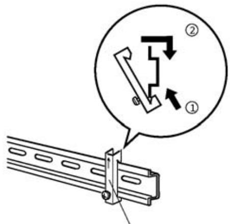
End Plate
Caution Always secure the Slave on the DIN track by installing End Plates on each side.
Mounting Direction
Any of the following six mounting directions can be used, unless specified in the Slave's operation manual.

3-2 Connector Installation (Special Flat Cable Only)
The cable connections can be made with simple connectors if Special Flat Cable is used for the communications cable. There are three types of connectors: the Branch Connector (refer to 3-2-1 Branch Connector), Extension Connector (refer to 3-2-2 Extension Connector), and Connector Terminator (refer to 3-2-3 Connector Terminator).
Caution Connectors cannot be reused once they have been attached to a cable. Be sure that the connectors are positioned correctly before attaching them.
Caution Wire the communications cable separately from power lines and high-voltage lines to prevent any noise.
Caution If Special Flat Cables are used for multiple CompoBus/S Systems, install the cables at least 5 mm apart from other Special Flat Cables to prevent unstable operation due to mutual interference in the CompoBus/S Systems.
When Special Flat Cable cable is used, determine which wires are to be used, as shown in the following diagram.
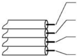
Communications power supply ^+ (BS + ) Brown
Communications data high (BD H) Black
Communications data low (BD L) White
Communications power supply - (BS-) Blue
3-2-1 Branch Connector
Connector Components
Branch Connectors are used to make branches from the main line. A commercially available terminal block can also be used to make branches.
The Branch Connector has three components: Cover 1, Cover 2, and the contact block. The following diagram shows Cover 1.
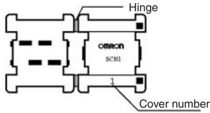
The following diagram shows Cover 2.
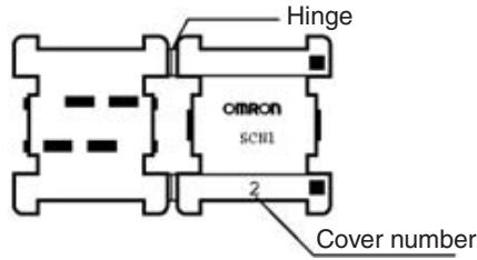
The following diagram shows the contact block.
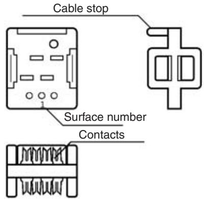
Note Cover 1 and Cover 2 can be distinguished by the cover number.
Installation Procedure
Use the following procedure to attach a Branch Connector to the communications cable.
The following procedure is an example to branch the main cable. The same procedure will apply even if the main line does not need to be distinguished from the branch lines.
1,2,3...
- Make a perpendicular cut in the cable that will be used as the branch line (the branch cable). The cable will not fit in the connector properly if the cut is not straight and perpendicular.
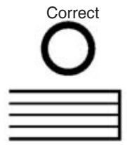
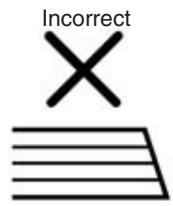
- Snap Cover 1 onto the branch cable. Make sure that the hook locks into place.
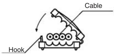
- Line up the end of Cover 1 with the end of the branch cable.
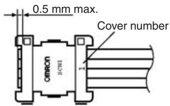
- Position Cover 1 onto Surface 1 of the contact block (the side with the cable stop). The pattern of the contact block is different on Surface 2, so Cover 1 cannot be fitted on Surface 2.

- Snap Cover 2 onto the cable being used as the main line (the main cable). Make sure that the hook locks into place. Cover 2 can still slide along the cable when locked.
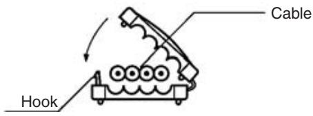
-
Slide Cover 2 to the point on the main cable where you want the branch line.
-
Position Cover 2 onto Surface 2 of the contact block (the side without the cable stop). Always align the cables so that the main cable's colors match the branch cable's colors.
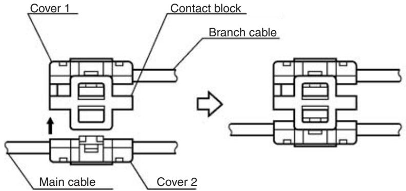
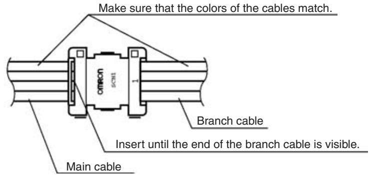
Caution The Units could be damaged if the branch cable's colors do not match the main cable's colors.
- The branch cable must be inserted all the way to the contact block's cable stop.
- Use a tool such as pliers to compress Cover 1 and Cover 2 together.
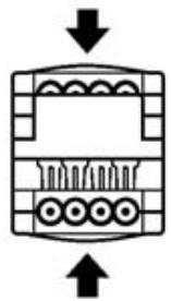
Caution Always align the tool with the centers of the Covers to prevent any bending or distortion when the connector is compressed. Uneven compression can prevent proper communications.
- Check the assembled connector from the side and make sure that the locks are completely engaged, as shown in the following diagram.
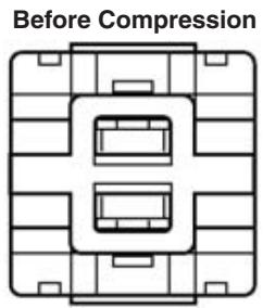

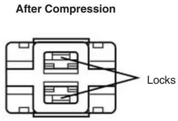
3-2-2 Extension Connector
Extension Connectors can be connected to any point of the communications cable regardless of whether it is a main or branch line or whether the main line needs to be distinguished from the branch lines.
Connector Components
The Extension Connector has three components: Cover 1, Cover 2, and the contact block. The following diagram shows Cover 1.
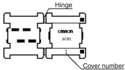
The following diagram shows Cover 2.
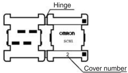
The following diagram shows the contact block.
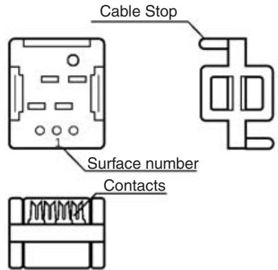
Note Cover 1 and Cover 2 can be distinguished by the cover number.
Installation Procedure
Use the following procedure to attach a Extension Connector to the communications cable.
1,2,3...
- Make perpendicular cuts in the cables being connected. The cables will not fit in the connector properly if the cuts are not straight and perpendicular.
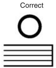
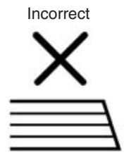
- Snap Cover 1 onto one of the cables. Make sure that the hook locks into place.
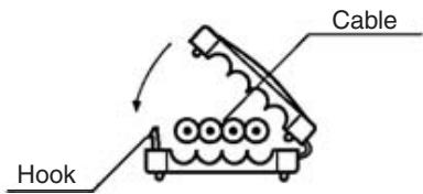
- Line up the end of Cover 1 with the end of the cable.
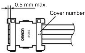
- Position Cover 1 onto Surface 1 of the contact block.
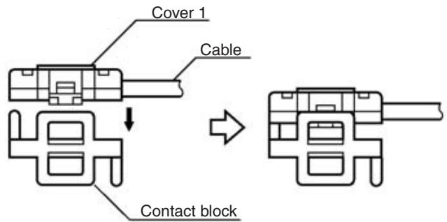
Note The patterns of the contact blocks are different, so Cover 1 cannot be fitted on Surface 2.
- Snap Cover 2 onto the other cable. Make sure that the hook locks into place.
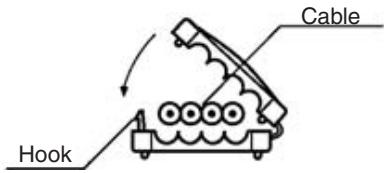
- Line up the end of Cover 2 with the end of the cable.
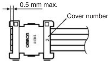
- Position Cover 2 onto Surface 2 of the contact block. Always align the cables so that their colors match.

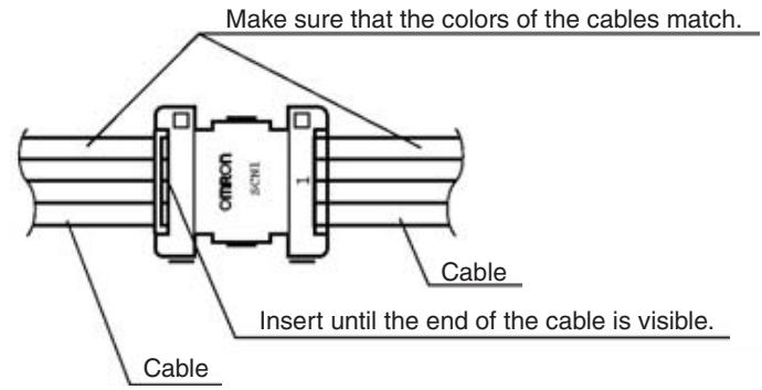
Caution The Units could be damaged if the cables' colors do not match.
- Make sure that each cable has been inserted all the way to the contact block's cable stop.
- Use a tool such as pliers to compress Cover 1 and Cover 2 together.
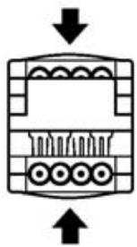
Caution Always align the tool with the centers of the Covers to prevent any bending or distortion when the connector is compressed. Uneven compression can prevent proper communications.
- Check the assembled connector from the side and make sure that the locks are completely engaged, as shown in the following diagram.
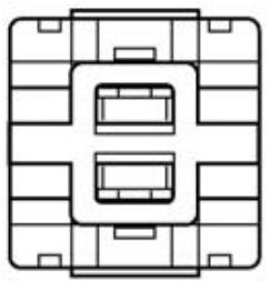
Before Compression

After Compression
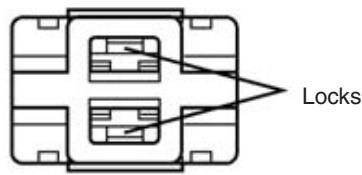
3-2-3 Connector Terminator
When the system has a main line that needs to be distinguished from the branch lines, a Connector Terminator is connected at the end of main line opposite the Master. If the main line does not need to be distinguished from the branch lines, a Connector Terminator is connected the end of the communications cable farthest from the Master.
Connector Components
The Connector Terminator has two components: Cover 1 and the contact block. The following diagram shows Cover 1.
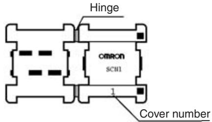
The following diagram shows the contact block.
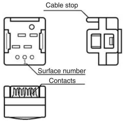
Installation Procedure
Use the following procedure to attach a Connector Terminator to the communications cable.
The following procedure is an example to connect a Connector Terminator to the main cable. The same procedure will apply even if the main line does not need to be distinguished from the branch lines.
1,2,3... 1. Make a perpendicular cut in the cable being used as the main line (the main cable). The cable will not fit in the connector properly if the cut is not straight and perpendicular.
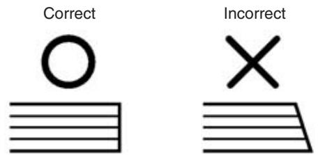
- Snap Cover 1 onto the main cable. Make sure that the hook locks into place.
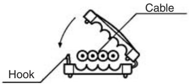
- Line up the end of Cover 1 with the end of the main cable.
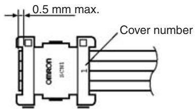
- Position Cover 1 onto Surface 1 of the contact block (the side with the cable stop).
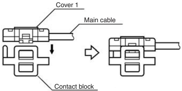
- Make sure that the cable has been inserted all the way to the contact block's cable stop.
- Use a tool such as pliers to compress Cover 1 and the contact block together.
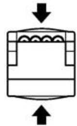
Caution
Always align the tool with the centers of the Covers and contact block to prevent any bending or distortion when the connector is compressed. Uneven compression can prevent proper communications.
- Check the assembled connector from the side and make sure that the locks are completely engaged, as shown in the following diagram.
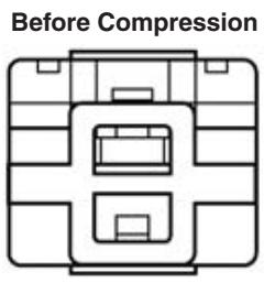

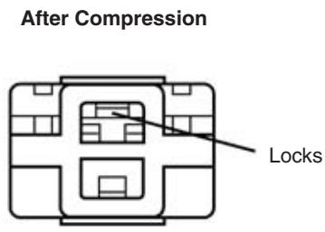
3-3 VCTF Cable Assembly
This section explains how to assemble VCTF cable components.
Commercially available 4-conductor VCTF cable and 2-conductor VCTF cable can be used as communications cable in CompoBus/S Systems.
Note
- Lay the communications cables separately from high-voltage lines and power lines to prevent noise interference.
- This section does not provide information on how to process shielded connectors (i.e., Round Water-resistant Connectors or Sensor I/O Connectors). Refer to the Sensor Catalog for information on how to process these connectors.
- When using commercially available VCTF cable, determine which signal wires will be used for the BD H, BD L, BS+, and BS- signals.
- When connecting 4-conductor VCTF cable to an assembly connector, check that the conductors and signals are connected in the following patterns.
| Conductor color | Signal combination | |||
| Pattern 1 | Pattern 2 | Pattern 3 | Pattern 4 | |
| White | BD H | BS+ | BS- | BD L |
| Red | BS+ | BS- | BD L | BD H |
| Green | BS- | BD L | BD H | BS+ |
| Black | BD L | BD H | BS+ | BS- |
3-3-1 Branching and Extending VCTF Cable
Use one of the following methods to branch or extend the VCTF cable.
- Commercially available relay terminal block (4-conductor/2-conductor VCTF cable branch or extension)
- T-joint or Combination Connector (4-conductor VCTF cable branch or extension)
Branching or Extension Using Relay Terminal Block
Install crimp terminals on each signal wire of the VCTF cable, and connect the two-wire cable (for extension) or three-wire cable (for branching) to a commercially available relay terminal block. Use crimp terminals on the signal wires that match the terminal block being used.
Note
-
Check that the signal wires are connected correctly. The Slave may be damaged if the signal wires, particularly those for the power supply, are connected to signal wires other than those specified.
-
Tighten the terminal block screws to a tightening torque that meets the terminal block specifications.
Example: Branching 2-Conductor VCTF Cable
Use a commercially available relay terminal block (a terminal block where the terminals facing each other are connected internally), and branch the cables as shown in the following diagram.
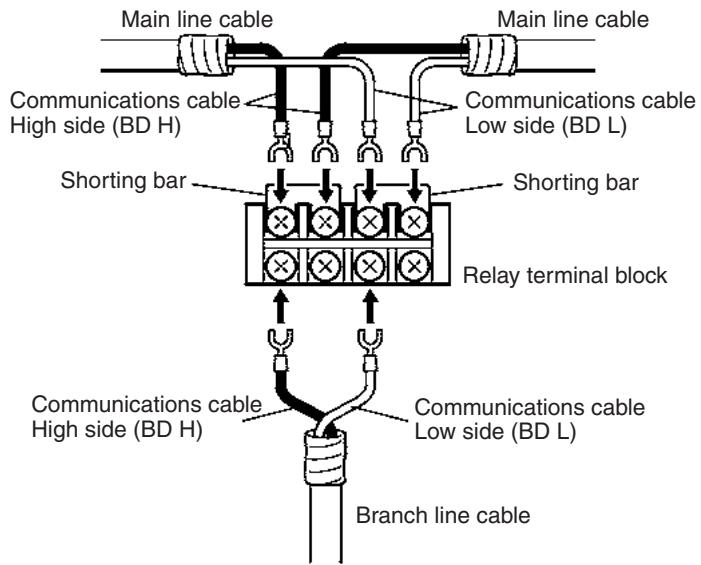
Branching or Extension Using T-joint Combination Connectors
When 4-conductor VCTF cable is used in locations that require water resistance, use XS2R-D427-5 T-joint Connectors or XS2C-D4□ or XS2G-D4□ Combination Connectors that are specially designed for CompoBus/S Systems.
Note
- Connectors with cables specially for CompoBus/S Systems are also available.
- For details on T-joint connectors, cable connectors, and connectors with cables, refer to 1-3-4 Connectors/Terminal Blocks.
Example: Branching 4-Conductor VCTF Cable Using T-joint
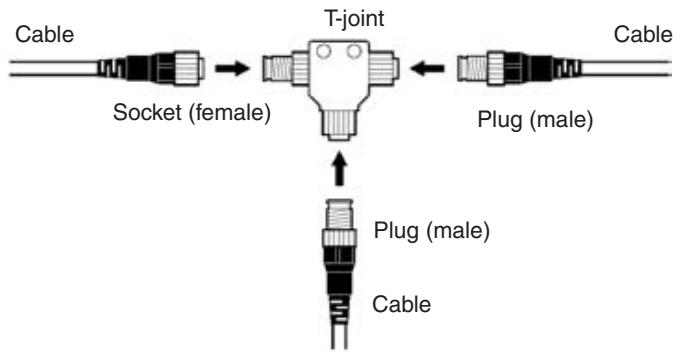
3-3-2 Installing Terminators
Use a Terminal-block Terminator or Shield Terminator as the terminator on the VCTF cable.
Note Refer to 1-3-4 Connectors/Terminal Blocks for details on Terminal-block terminators, T-joints, and Connectors.
Terminal-block Terminators
When the VCTF cable is connected to an SRS1-T Terminal-block Terminator, use crimp terminals on each of the BD H and BD L signal wires, and connect them to each terminal. The signal wires can be connected to any of the terminals.
Note 1. Do not connect both signal wires to a single terminal.
- When connecting the communications power supply using Special Flat Cable or 4-conductor VCTF cable, insulate the BD+ and BS- power supply cables.
Tighten the terminal screws to the specified tightening torque (0.3 to 0.5 N·m). - When connecting Terminal-block Terminators to VCTF cables, use the same crimp terminals as those used to connect the communications cables to the Slaves. (Refer to 3-4 Master/Slave Connecting Cables.)
Shield Terminators
When using 4-conductor VCTF cable, terminators can be connected by connecting an SRS2-1 Shield Terminator to the T-joint.
Note The SRS2-1 Shield Connector has a male plug. Connect it to the female socket connector of the T-joint.
3-4 Master/Slave Connecting Cables
This section describes the methods used for connecting communications cables to each device and installing connectors on the Connector Terminal and Sensor Terminal cables.
3-4-1 Crimp Terminal Installation
Attach crimp terminals to the ends of the communications cable when connecting the cable to a Master, Slave, Terminal-block Terminator, or commercially available terminal block.
Caution Do not connect bare signal wires to the terminals since the wires could short and damage the Unit to which they are connected.
Note Do not strip too much insulation from the wires when preparing the cable for the crimp terminals. Cover the shaft of the terminal connector and the end of the wire with electrical tape or heat-shrinking tube.
Master or Slave
When connecting communications cable (VCTF cable or Special Flat Cable) to a Master or Slave, attach an M3 crimp terminal like those shown below to each signal wire.
M3 Terminals for the Master Unit (Except CJ Series)
| 6.2 mm max. |
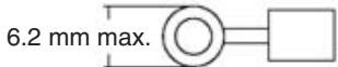
| Recommended terminal | Comment |
| Nippon Crimp Terminal 1.25-N3A | Forked terminal |
| Molex Y1.25-3.5L | Forked terminal |
Note Refer to 4-3-3 Wiring and Installing Communications Cables for details on crimp terminals used for connecting CJ-series Master Units.
M3 Terminals for Slave Units
| 6.0 mm max. |
| Recommended terminal (standard JIS part numbers) |
| RAV1.25-3 |
| RAP1.25-3 |
3-4-2 Master and Slave Terminal Connections
When connecting the communications cable to the terminals of a Master node or those of a Slave node, connect the BD H signal wire to the BD H terminal and the BD L signal wire to the BD L terminal.
When supplying power to the Slave's communications power supply, connect the BS+ wire to the BS+ terminal and the BS- wire to the BS- terminal. The following diagram shows the multi-drop connection method.
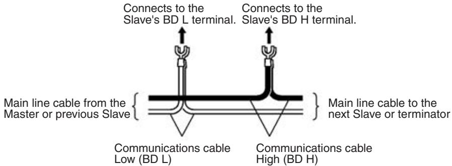
Caution
Do not mix up the wires when connecting the communications cable. In particular, the Slave might be damaged if the power wires are connected to the wrong terminals.
When power is being supplied through Special Flat Cable but some Slaves are being supplied from another source, always insulate the BS+ and BS-wires.
Tighten the terminal screws to the specified tightening torque (0.3 to 0.5 N·m).
3-4-3 Cable Connector Wiring and Assembly
When using the Slaves shown in the following table, attach the special OMRON cable connectors to the cables of the sensors and other external devices.
| Slave type | Model |
| Connector Terminals with Transistor Inputs | SRT2-VID08S (-1) |
| Connector Terminals with Transistor Outputs | SRT2-VOD08S (-1) |
| Sensor Terminals with Connector Outputs | SRT□-OD08S |
| Sensor Terminals | SRT□-ID08S SRT□-ND08S |
Assembling the Cable Connectors
Use the following procedure to install the sensor's cable into the cable connector that plugs into the Sensor Terminal. The following diagram shows the two parts of the cable connector: the connector plug and cover.
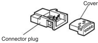
Cable Connector Model Numbers
There are two models of cable connectors available for different sized cable wires, as shown in the following table.
| Model | Marking | Compatible cable wire size (cross-sectional area) |
| XS8A-0441 | XS8-1 | 0.3 to 0.5 mm² |
| XS8A-0442 | XS8-2 | 0.14 to 0.2 mm² |
Make sure that the sensor cable's wire size is compatible the cable connector being used. The cable connector's marking is found on the connector plug, as shown in the following diagram.
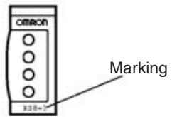
Sensor Cable Preparation
Sensor cables are usually stripped to semi-strip or strip specifications, but OMRON cable connectors cannot be attached when the cable is stripped in these ways.
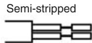
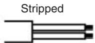
To prepare the cable for an OMRON cable connector, cut the tip and strip the cable insulation but not the wire insulation, as shown in the following diagram.
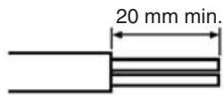
Inserting Wires into the Cover
When connecting the Sensor, match the terminal numbers marked on the connector cover with the colors of the sensor wires as shown in the following table.
| Sensor terminal | Sensor type | Terminal number | |||
| 1 | 2 | 3 | 4 | ||
| SRT2-VID08S | 3-wire sensor (without self-diagnostic output function) | Black (white) (Connect to 1 or 2) | Brown (red) | Blue (black) | |
| 2-wire sensor (without self-diagnostic output function) | Brown (white) (Connect to 1 or 2) | --- | Blue (black) | ||
| SRT2-VID08S-1 | 3-wire sensor (without self-diagnostic output function) | Black (white) (Connect to 1 or 2) | Brown (red) | Blue (black) | |
| 2-wire sensor (without self-diagnostic output function) | Blue (black) (Connect to 1 or 2) | Brown (white) | --- | ||
| Sensor terminal | Sensor type | Terminal number | |||
| 1 | 2 | 3 | 4 | ||
| SRT□-ID08S | 3-wire sensor (without self-diagnostic output function) | Black (white) | --- | Brown (red) | Blue (black) |
| 2-wire sensor (without self-diagnostic output function) | Brown (white) | --- | --- | Blue (black) | |
| SRT□-ND08S | Sensor with teaching function or external diagnostic function | Black (white) | Pink (gray) | Brown (red) | Blue (black) |
| Sensor with bank switching function | Black | Purple | Brown | Blue | |
Note In accordance with the changes in the standards for photoelectric sensors and proximity sensors, wire colors have been changed. Colors in parentheses are the old wire colors.
When connecting an output device, match the terminal numbers marked on the connector cover with the signal wires of the output device as shown in the following table.
| Sensor terminal | Terminal number | |||
| 1 | 2 | 3 | 4 | |
| SRT2-VOD08S | Yes (Connect to 1 or 2) | Yes | --- | |
| SRT2-VOID08S-1 | Yes (Connect to 1 or 2) | --- | Yes | |
| SRT□-OD08S | Yes | --- | Yes (Connect to 3 or 4) | |
Insert the wire all the way into the cover's hole until it touches.
Connector Assembly
Use the following procedure to assemble the cable connector.
1,2,3...
- Check the wire colors and make sure that the sensor's wires are aligned with the correct terminal numbers. (The cover is semi-transparent, so the wire colors will be visible through the cover.)
- Fit the cover (with wires inserted) into the connector plug, as shown in the following diagram.
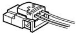
- Use a tool such as pliers to press the cover all the way into the connector plug. Always align the tool with the center of the cover so it does not tilt,
and press the cover straight into the connector plug. There should not be any gap between the cover and plug.
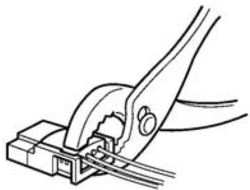
Inserting and Removing Cable Connectors
The sensor cable can be inserted into the Sensor Terminal once the cable connector has been attached.
Inserting the Cable Connector
Position the cable connector so that Terminal 1 faces you and push the connector into the Sensor Terminal until it clicks into place.
Removing the Cable Connector
To remove the cable connector, first pull out the lock lever and then remove the cable connector, as shown in the following diagram.
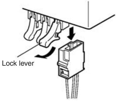
3-5 Operations Checklist
Go through the items in the following checklist before turning ON the Units in the CompoBus/S System. All of the checks should be answered "Yes."
| Item | Check | Answer | |
| CS-series, C200HX/C200HG/ C200HE-(Z)E, and C200HS Master Units | Switch settings | Has the Master's Special I/O Unit unit number been set? (Refer to 4-1-2 Switch Settings for details.) | Yes No |
| Has the node number been set with pin 1 of the DIP switch? (Refer to 4-1-2 Switch Settings for details.) | Yes No | ||
| Has the communications mode been set with pin 2 of the DIP switch? (Refer to 4-1-2 Switch Settings for details.) | Yes No | ||
| Are pins 3 and 4 of the DIP switch all set to OFF? | Yes No | ||
| CS-series Master Units | Switch settings | Has the Master's Special I/O Unit number been set?(Refer to 4-2-2 Switch Settings for details.) | Yes No |
| Has the node number been set with pin 1 of the DIP switch?(Refer to 4-2-2 Switch Settings for details.) | Yes No | ||
| Has the communications mode been set with pin 2 of the DIP switch?(Refer to 4-2-2 Switch Settings for details.) | Yes No | ||
| Has the communications stop mode been set with pin 3 of the DIP switch?(Refer to 4-2-2 Switch Settings for details.) | Yes No | ||
| Has the Slave registration function been set with pin 4 of the DIP switch?(If the Slave registration function is used, the CPU Unit's DM Area must also be set.) | Yes No | ||
| (Refer to 4-2-2 Switch Settings for details.) | |||
| CJ-series Master Units | Switch settings | Has the Master's Special I/O Unit number been set?(Refer to 4-3-2 Switch Settings for details.) | Yes No |
| Has the node number been set with pin 1 of the DIP switch?(Refer to 4-3-2 Switch Settings for details.) | Yes No | ||
| Has the communications mode been set with pin 2 of the DIP switch?(Refer to 4-3-2 Switch Settings for details.) | Yes No | ||
| Has the communications stop mode been set with pin 3 of the DIP switch?(Refer to 4-3-2 Switch Settings for details.) | Yes No | ||
| Has the Slave registration function been set with pin 4 of the DIP switch?(If the Slave registration function is used, the CPU Unit's DM Area must also be set.) | Yes No | ||
| (Refer to 4-3-2 Switch Settings for details.) | |||
| CQM1 Master Units | Switch settings | Has the PLC word allocation (DIP switch pins 1 and 2) been set?(Refer to 4-4-2 Switch Settings for details.) | Yes No |
| Has the number of points/node number setting (DIP switch pin 3) been set?(Refer to 4-4-2 Switch Settings for details.) | Yes No | ||
| Has the communications mode been set with pin 4 of the DIP switch?(Refer to 4-4-2 Switch Settings for details.) | Yes No | ||
| Are pins 5 and 6 of the DIP switch all set to OFF? | Yes No | ||
| Slaves | Switch settings | Has the node number been set?(Refer to SECTION 5 Slave Specifications and Operations for details.) | Yes No |
| Has the communications mode been set?(Refer to SECTION 5 Slave Specifications and Operations for details.) | Yes No | ||
| Is the Slave's node number unique (not allocated to another Slave)? | Yes No | ||
| Have other settings besides the CompoBus/S settings, such as the "hold/clear outputs for communications error" setting, been set?(Refer to SECTION 5 Slave Specifications and Operations for details.) | Yes No | ||
| Wiring | Master | Is the Master Unit connected at the end of the main line when the main line needs to be distinguished from the branch lines.? | Yes No |
| Is the cable connected to the Master correctly? (Refer to 3-4 Master/Slave Connecting Cables for details.) | Yes No | ||
| With CQM1 Masters, has the alarm output terminal been wired? (Refer to 6-4-2 Error Detection with the Alarm Output (CQM1 Only) for details.) | Yes No | ||
| Slave | Are the cables connected to the Slaves correctly? (Refer to 3-4 Master/Slave Connecting Cables for details.) | Yes No | |
| Is there just one Slave connected to each branch line when the main line needs to be distinguished from the branch lines? (Refer to 2-2-1 Main Line/Branch Line Connections for details.) | Yes No | ||
| Terminator | Has just one terminator been connected at the end of the main line opposite the Master? (Refer to 2-2-3 Terminator Connection for details.) | Yes No | |
| Main line length | When the main line needs to be distinguished from the branch lines, is the length of the main line within specifications? (Refer to 2-2-2 Maximum Cable Length for details.) | Yes No | |
| Branch line lengths | When the main line needs to be distinguished from the branch lines, is the length of the each branch line within specifications? (Refer to 2-2-2 Maximum Cable Length for details.) | Yes No | |
| Total branch line length | When the main line needs to be distinguished from the branch lines, is the total length of the branch lines within specifications? (Refer to 2-2-2 Maximum Cable Length for details.) | Yes No | |
| Number of Slaves | Is the number of Slaves within the limit set on the Master? (Refer to SECTION 4 Master Unit Specifications and Operations for details.) | Yes No | |
| When using 4-conductor VCTF cable or Special Flat Cable, are the main line length and total branch line length of the system with a maximum of 16 Slaves within specifications? (Refer to 2-2-2 Maximum Cable Length for details.) | Yes No | ||
| Cable | Has just one kind of cable (Special Flat Cable or VCTF cable) been used in the CompoBus/S System? | Yes No | |
| If Special Flat Cables are used for multiple CompoBus/S Systems, install the cables at least 5 mm apart from other Special Flat Cables. | Yes No | ||
| Noise | Is the wiring separated from any power/high-voltage lines? | Yes No | |
| Cable | 2-conductor VCTF cable | Has 2-conductor (0.75 mm²) cable been used? | Yes No |
| 4-conductor VCTF cable | Has 4-conductor (0.75mm²) cable been used? | Yes No | |
| Has the 4-conductor cable power supply been used to supply power to the Slaves only (not for other purposes, such as I/O power supply)? | Yes No | ||
| Special Flat Cable | Has the Special Flat Cable power supply been used to supply power to the Slaves only (not for other purposes, such as I/O power supply)? | Yes No | |
| Power supply | 4-conductor VCTF Cable, Special Flat Cable | Does the power supply configuration match the plan? (Refer to 2-3 Supplying Power to the Slaves for details.) | Yes No |
| With local and dual power supply Slaves, is there a separate power supply for the I/O? (Refer to 2-3 Supplying Power to the Slaves for details.) | Yes No | ||
| 2-conductor VCFF cable | Have the Slaves been wired correctly? (The Units can be damaged if the power supply is connected to the communications terminals.) (Refer to 2-3 Supplying Power to the Slaves for details.) | Yes No | |
SECTION 4
Master Unit Specifications and Operations
This section provides information on the specifications and functions of each Master Unit, including details on switch settings and allocation of Slave I/O.
4-1 C200HW-SRM21-V1 Master Unit for CS-series, C200HX/C200HG/C200HE-(Z)E, and C200HS PLCs 74
4-1-1 Specifications and Part Names 74
4-1-2 Switch Settings. 76
4-1-3 I/O Allocations in CS-series, C200HX/C200HG/C200HE-(Z)E, and C200HS PLCs 78
4-1-4 Data Areas in the PLC 85
4-2 CS1W-SRM21 Master Unit for CS-series PLCs 88
4-2-1 Specifications and Part Names 88
4-2-2 Switch Settings 90
4-2-3 I/O Allocations 92
4-2-4 Slave Registration Function and Communications Stop Mode 98
4-2-5 Allocations for Master Unit in PLC 103
4-3 CJ1W-SRM21 Master Unit for CJ-series PLCs 104
4-3-1 Specifications and Part Names 104
4-3-2 Switch Settings 107
4-3-3 Wiring and Installing Communications Cables 109
4-3-4 I/O Allocations 114
4-3-5 Slave Registration Function and Communications Stop Mode 120
4-3-6 Allocations for Master Unit in PLC 125
4-4 CQM1-SRM21-V1 Master Unit for CQM1 PLCs 126
4-4-1 Specifications and Part Names 126
4-4-2 Switch Settings 129
4-4-3 I/O Allocations in CQM1 PLCs 130
4-5 SRM1-C0□-V2 Master Control Units 136
4-5-1 Specifications and Part Names 136
4-5-2 Settings 140
4-6 CPM2C-S Series CPM2C-S□□□C (-DRT). 140
4-6-1 Specifications and Part Names 141
4-6-2 Settings 144
4-1 C200HW-SRM21-V1 Master Unit for CS-series, C200HX/C200HG/C200HE-(Z)E, and C200HS PLCs
4-1-1 Specifications and Part Names
CS-series, C200HX/C200HG/C200HE-(Z)E, and C200HS PLCs use the C200HW-SRM21-V1 Master Unit.
Specifications
General Specifications
General specifications conform to those of the CS-series, C200HX/C200HG/ C200HE-(Z)E, and C200HS PLCs.
Performance Specifications
| Item | Specifications | |
| Model | C200HW-SRM21-V1 | |
| Unit classification | Special I/O Unit | |
| Internal current consumption | 5 V DC, 150 mA max. | |
| Weight | 200 g max. | |
| Max. number of Masters | 10 or 16 Units (See note.) | 5 or 8 Units (See note.) |
| Master Unit mounting location | Can be mounted on the CPU Backplane or Expansion I/O Backplane. Can't be mounted on a SYSMAC BUS Slave (RT). | |
| Max. number of I/O points per Master | 128 points (64 inputs/64 outputs) | 256 points (128 inputs/128 outputs) |
| Number of points per node number | 8-point mode | |
| Number of usable node numbers per Master | IN0 to IN7 and OUT0 to OUT7 (up to 16 Units can be connected) | IN0 to IN15 and OUT0 to OUT15 (up to 32 Units can be connected) |
Note The following table shows the maximum number of Master Units that can be connected and the node number settings for each Master according to the CPU Unit to which it is mounted.
| CPU Unit | Number of connectable Master Units | |
| IN0 to IN7, OUT0 to OUT7 | IN0 to IN15, OUT0 to OUT15 | |
| C200HX-CPU3☐/4☐-(Z)EC200HG-CPU3☐/4☐-(Z)EC200HE, and C200HS | 10 Units | 5 Units |
| C200HX-CPU5☐/6☐/8☐-(Z)EC200HG-CPU5☐/6☐-(Z)E, and CS | 16 Units | 8 Units |
Dimensions
The following diagram shows the dimensions of the C200HW-SRM21-V1 Master Unit. All dimensions are in mm.
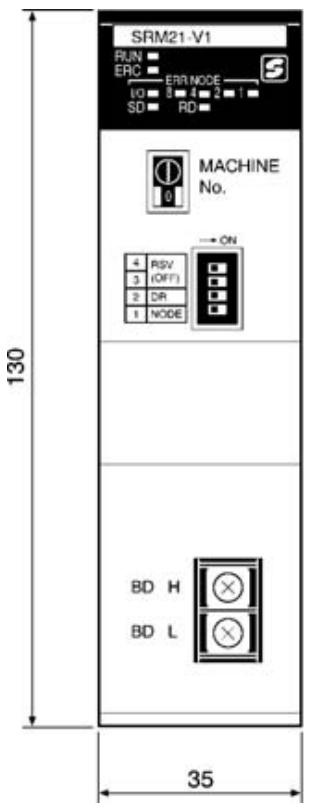
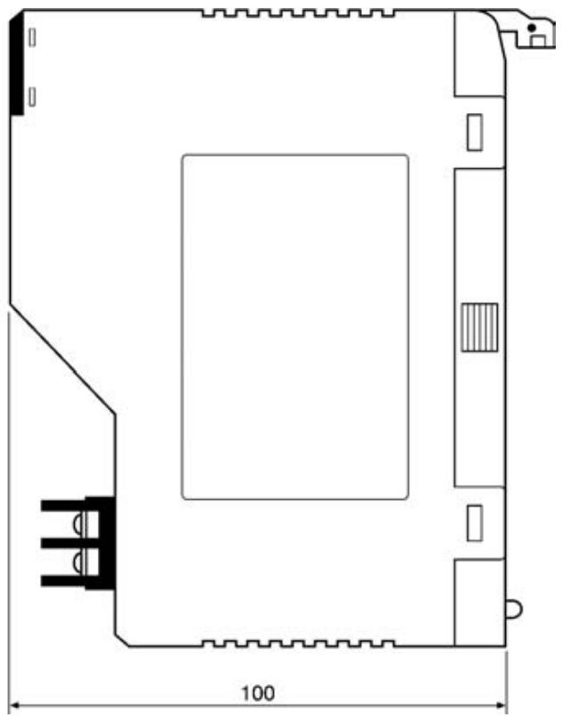
Note Refer to the CS-series Operation Manual, C200HX/C200HG/C200HE-(Z)E Operation Manual, or C200HS Operation Manual for details on the dimensions when the Master Unit is installed on the PLC's Backplane.
Master Unit Components
The following diagram shows the main components of the C200HW-SRM21-V1 Master Unit. The functions of these components are described below.
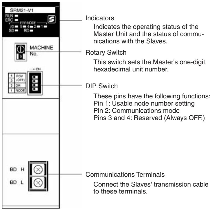
Indicators
The following table shows the meaning of the indicators.
| Indicator | Status | Meaning |
| RUN (green) | ON | The Unit is operating normally. |
| OFF | Indicates one of the following conditions:The power is OFF, there is an I/O setting error, the CPU Unit is in standby status, or there is a unit number setting error. | |
| SD (yellow) | ON | Data is being transmitted. |
| OFF | Data is not being transmitted. | |
| RD (yellow) | ON | Data is being received. |
| OFF | Data is not being received. | |
| ERC (red) | ON | A Slave has been withdrawn from communications.(Communications error) |
| OFF | The Slaves are communicating normally. | |
| IN/OUT (red) | ON | An error has occurred with an Output Slave. |
| OFF | An error has occurred with an Input Slave or all Slaves are operating normally. | |
| 8421 (red) | ON/OFF | These indicators represent the four-digit binary slave number of the Slave in which the error occurred. |
4-1-2 Switch Settings
Rotary Switch
The Master Unit's unit number (Special I/O Unit's unit number) is set with the rotary switch on the front of the Unit.
MACHINE
No.
The highest possible unit number depends on the PLC model and the usable node number setting set with pin 1 of the DIP switch.
| CPU Unit | Number of usable Master Units | Usable node number setting(with DIP switch) | Unit number setting range |
| CS1 | 16(allocated words for 1 Special I/O Unit (i.e., 10 words)) | IN0 to IN7 and OUT0 to OUT7 | 0 to F |
| 8(allocated words for 2 Special I/O Units (i.e., 20 words)) | IN0 to IN15 and OUT0 to OUT15 | 0 to E | |
| C200HX-CPU3☐-(Z)E/-CPU4☐-(Z)E, C200HG-CPU3☐-(Z)E/-CPU4☐-(Z)E, AllC200HE/HS PLCs | 10(allocated words for 1 Special I/O Unit (i.e., 10 words)) | IN0 to IN7 and OUT0 to OUT7 | 0 to 9 |
| 5(allocated words for 2 Special I/O Units (i.e., 20 words)) | IN0 to IN15 and OUT0 to OUT15 | 0 to 8 | |
| C200HX/HG-CPU5☐-(Z)E/CPU6☐-(Z)E/CPU8☐-(Z)E | 16(allocated words for 1 Special I/O Unit (i.e., 10 words)) | IN0 to IN7 and OUT0 to OUT7 | 0 to 9, A to F |
| 8(allocated words for 2 Special I/O Units (i.e., 20 words)) | IN0 to IN15 and OUT0 to OUT15 | 0 to 8, A to E |
Any unit number in the ranges above can be set, as long as the same unit number has not been set on another Special I/O Unit mounted in the PLC. Set the unit number with a small flat-blade screwdriver, being careful not to damage the switch.
Caution Always turn OFF the PLC before changing the unit number setting.
- The Master Unit is shipped with the unit number set to 0.
- The unit number setting determines which words in the PLC's Special I/O Unit Area are allocated to the Master Unit. Refer to 4-1-3 I/O Allocations in CS-series, C200HX/C200HG/C200HE-(Z)E, and C200HS PLCs for details.
- The Master Unit is allocated twice as many words in the PLC's Special I/O Unit Area (the words for unit number set on the Master and the next unit number) when the usable node number setting is set to IN0 through IN15 and OUT0 through OUT15. In this case, neither the Master's unit number nor the next unit number can be used on another Special I/O Unit mounted in the PLC.
- If the same unit number is used for the Master and another Special I/O Unit, an I/O UNIT OVER error will occur in the PLC and it will not be possible to start up the CompoBus/S System.
- For the following PLCs, unit numbers A to F cannot be set: C200HE, C200HS, C200HG-CPU33-(Z)E, C200HG-CPU43-(Z)E, C200HX-CPU34-(Z)E, and C200HX-CPU44-(Z)E
DIP Switch
The DIP switch is used to set the range of usable node numbers of Slaves and the communications mode.
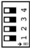
Reserved (Always OFF.)
Communications mode
- Usable node numbers
Note 1. Always turn the PLC OFF before changing the settings.
- Leave pins 3 and 4 set to OFF.
Set pin 1 of the DIP switch as shown in the following table.
| Pin 1 setting | Usable node number setting |
| OFF | IN0 to IN7 and OUT0 to OUT7 |
| ON | IN0 to IN15 and OUT0 to OUT15 |
Set pin 2 of the DIP switch as shown in the following table.
| Pin 2 setting | Communications mode setting | Communications distance | Communications baud rate | Communications cycle time |
| OFF | High-speed Communications Mode | 100 m max. | 750 kbps | 0.5 ms or 0.8 ms |
| ON | Long-distance Communications Mode | 500 m max. | 93.75 kbps | 4.0 ms or 6.0 ms |
Note
- Make sure that the communications mode of the Master Unit matches that of all Slaves. If the CompoBus/S System contains a Slave whose communications mode does not agree with that of the Master Unit, the COMM indicator on that Slave will not light, and normal communications with that Slave will not be possible. Other Slaves will not be adversely affected. (In such cases, the COMM indicator on the Master Unit will light normally.) For information relating to the states of the Master Unit indicator, refer to 6-5-1 Indicators.
-
When using an existing Master Unit model without V1, pin 2 must be set to OFF. Otherwise, normal communications may not be possible.
-
The Master Unit is factory-set to OFF (for IN0 to IN7 and OUT0 to OUT7).
- The maximum number of Slaves setting affects both the total number of words allocated and the Slaves' communication cycle. Refer to 4-1-3 I/O Allocations in CS-series, C200HX/C200HG/C200HE-(Z)E, and C200HS PLCs for details.
- The Master Unit is allocated twice as many words in the PLC's Special I/O Unit Area (the words for unit number set on the Master and the next unit number) when the usable node number setting is set to IN0 to IN15 and OUT0 to OUT15. In this case, neither the Master's unit number nor the next unit number can be used on another Special I/O Unit mounted in the PLC.
- Pin 2 is factory-set to OFF (High-speed Communications Mode).
- The setting of pin 2 determines the communications distance, baud rate, and cycle time as shown in the above table.
4-1-3 I/O Allocations in CS-series, C200HX/C200HG/C200HE-(Z)E, and C200HS PLCs
In CS-series, C200HX/C200HG/C200HE-(Z)E, and C200HS PLCs, the Master Unit is treated as a Special I/O Unit, so the Slave's I/O data and status information are stored in the sections of the PLC's data areas which are allocated to Special I/O Units.
Allocations and Master Unit Settings
The following settings affect I/O allocations to Slaves in the Master Units used with CS-series, C200HX/C200HG/C200HE-(Z)E, and C200HS PLCs.
| Setting at Master Unit | Status | Affect on allocation |
| Usable node number settings (DIP switch pin 1) | OFF | Uses 10 words (for one unit number) from the Special I/O Unit Area as follows: Output: 4 words, input: 4 words, status: 2 words. |
| ON | Uses 20 words (for two unit numbers) from the Special I/O Unit Area as follows: Output: 8 words, input: 8 words, status: 4 words. | |
| Unit number setting (rotary switch) | n | First word of the area used in the Special I/O Unit Area CS Series 2000 + n × 10 C200HX/HG/HE/HS For 0 ≤ n ≤ 9: 100 + n × 10 For 10 ≤ n ≤ 15 (A to F): 400 + (n - 10) × 10 |
Slave Allocations
Slaves are allocated words in the Special I/O Unit Area as described next. In CompoBus/S Systems, node numbers of Input Slaves and Output Slaves are treated separately so the same node number can be allocated.
I/O Allocations when Pin 1 Is OFF
When pin 1 is OFF and node addresses IN0 to IN7 and OUT0 to OUT7 (up to 64 inputs/64 outputs) are used, words are allocated to the Slaves for each node number as shown in the following diagrams.
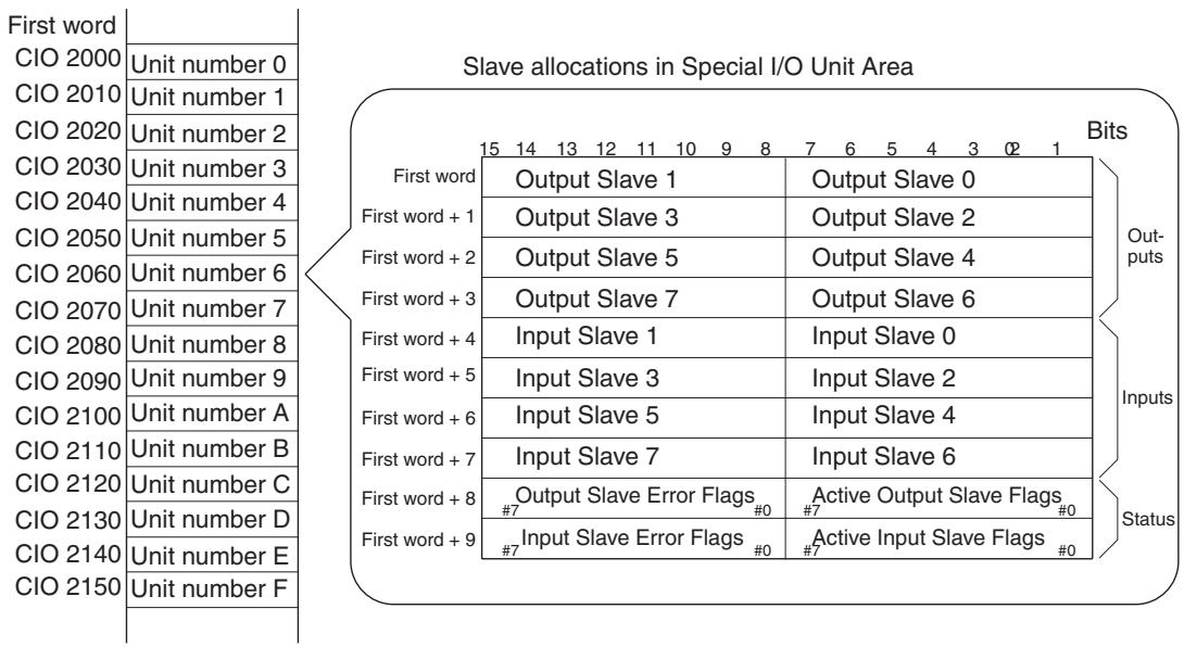
CS-series PLCs
C200HX/C200HG/C200HE-(Z)E, and C200HS PLCs
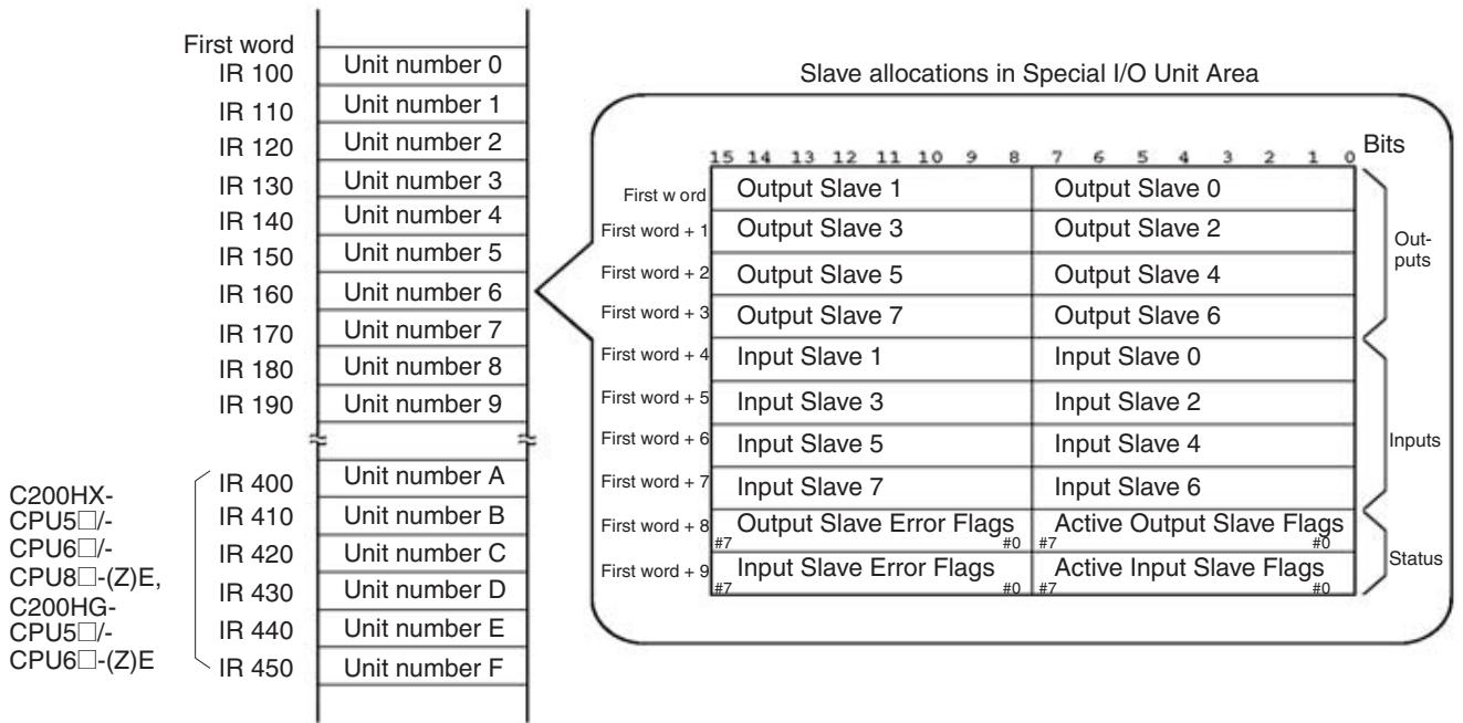
I/O Allocations when Pin 1 is ON
When pin 1 is ON and node addresses IN0 to IN15 and OUT0 to OUT15 (128 inputs/128 outputs max) are used, words are allocated to the Slaves for each node number as shown in the following diagrams.
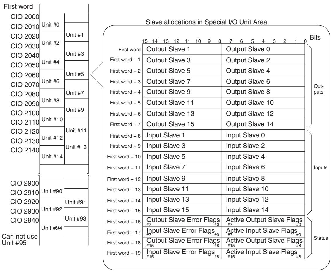
CS-series PLCs
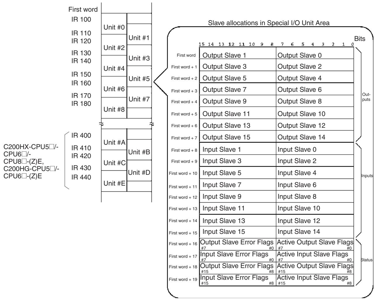
C200HX/C200HG/C200HE-(Z)E, and C200HS PLCs
Slave I/O and Corresponding Allocations
Slave with 8 Inputs or 8 Outputs
The Slave is treated as one node number for output or input.
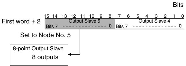
Slave with 16 Inputs or 16 Outputs
The Slave is treated as two node numbers for output or input, and allocated in the same words as follows:
- When an odd node number has been set:
Uses node number setting – 1 and node number setting - When an even node number has been set:
Uses node number setting and node number setting +1
Example: When a 16-point Output Slave set as node number 5, the areas for Output Slaves 4 and 5 are used. Other Output Slaves cannot use the area allocated for Output Slave 4.
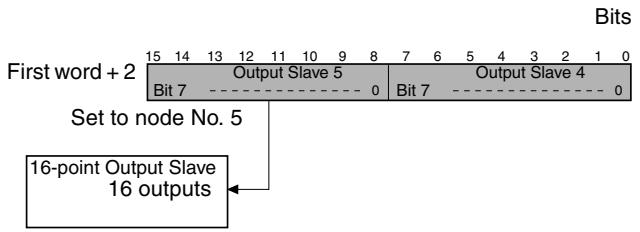
Slave with Mixed I/O (8 Inputs and 8 Outputs)
Slaves that have both outputs and inputs are also assigned a single node number, so the same node number is used for both outputs and inputs.
Example: When a Slave with 8 inputs and 8 outputs set as node number 2, the area for node number 2 outputs and inputs is used.
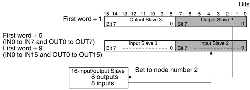
Slave with 4 Outputs or 4 Inputs
The Slave is treated as one node number for output or input. The Slave uses the rightmost 4 bits only, however, of the area allocated for one node number. (The leftmost 4 bits cannot be used by another Slave.)
- When an odd node number has been set:
Bits 8 to 11 are used and bits 12 to 15 are not used. - When an even node number has been set:
Bits 0 to 3 are used and bits 4 to 7 are not used.
Example: When a Slave with 4 inputs is set as node number 7, the Slave is allocated the rightmost 4 bits (bits 8 to 11) in the area assigned for input node number 7.
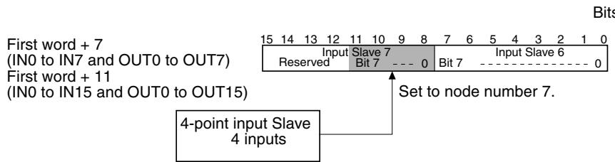
Slave with Mixed I/O (4 Outputs and 4 Inputs)
Slaves that have both outputs and inputs are also assigned a single node number, so the same node number is used for both outputs and inputs. The Slave uses the rightmost 4 bits only, however, of the area allocated for one node number. (The leftmost 4 bits cannot be used by another Slave.)
- When an odd node number has been set:
Bits 8 to 11 are used and bits 12 to 15 are not used.
- When an even node number has been set:
Bits 0 to 3 are used and bits 4 to 7 are not used.
Example: When a Slave with 4 outputs and 4 inputs is set to node number 2, the rightmost 4 bits (bits 0 to 3) of the area for node number 2 for both output and input are used.
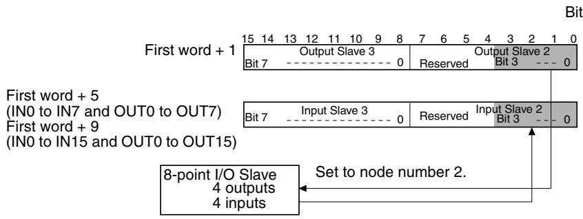
Slave with 32 Outputs or 32 Inputs
The Slave is treated as four node numbers for output or input and is allocated 2 consecutive words, as follows:
- When an odd node number has been set:
Uses (node number setting - 1) to (node number setting + 2) - When an even node number has been set:
Uses (node number setting) to (node number setting + 3).
Example: When a Slave with 32 outputs is set to node number 1, it uses the area assigned for Output Slave 0 to Output Slave 3. The area for Output Slave 0, 2, and 3 cannot be used for another Output Slave.
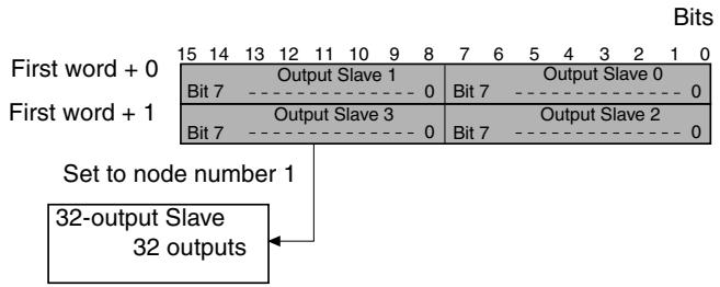
Slave with Mixed I/O (16 Outputs and 16 Inputs)
Slaves that have both outputs and inputs are also assigned a single node number, so the same node number is used for both outputs and inputs, and each is regarded as two node numbers. Outputs and inputs are allocated to the same words, as follows:
- When an odd node number has been set:
Uses (node number setting - 1) and (node number setting) -
When an even node number has been set:
Uses (node number setting) and (node number setting + 1). -
Example: When a Slave with 16 inputs and 16 outputs is set to node number 3, it uses Output Slave 2 and 3, and Input Slave 2 and 3. Output Slave 2 and Input Slave 2 cannot be used by other Slaves.
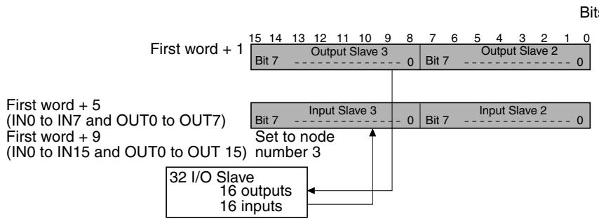
An Analog Terminal uses 64, 48, 32, or 16 points. I/O allocations are shown in the following table.
| Number of points allocated | Node number setting | Node numbers used |
| 64 pointsSRT2-AD04: 4 inputs | Odd number | Node number setting - 1 to node number setting + 6 |
| Even number | Node number setting to node number setting + 7 | |
| 48 pointsSRT2-AD04: 3 inputs | Odd number | Node number setting - 1 to node number setting + 4 |
| Even number | Node number setting to node number setting + 5 | |
| 32 pointsSRT2-AD04: 2 inputsSRT2-DA02: 2 outputs | Odd number | Node number setting - 1 to node number setting + 2 |
| Even number | Node number setting to node number setting + 3 | |
| 16 pointsSRT2-AD04: 1 inputSRT2-DA02: 1 output | Odd number | Node number setting - 1 to node number setting |
| Even number | Node number setting to node number setting + 1 |
Do not allow allocations for the node numbers that are actually used to extend beyond the words allocated to the Master Unit. Participation in communications will not be possible and the COMM indicator will turn OFF if the words allocated to the Master are exceeded for either inputs or outputs.
Status Flag Functions
The functions of the flags in the status area are described below.
Active Output Slave Flags
These flags indicate which Output Slaves (0 to 15) are active nodes in the system. When the corresponding flag is ON, the Slave is an active node. All of these flags are reset when the power is turned ON or operation is restarted.
0 (OFF): No communications participation
The node hasn't participated in communications even once.
1 (ON): Communications participation
The flag won't change even if the node is withdrawn from the system.
Active Input Slave Flags
These flags indicate which Input Slaves (0 to 15) are active nodes in the system. When the corresponding flag is ON, the Slave is an active node. All of these flags are reset when the power is turned ON or operation is restarted.
0 (OFF): No communications participation
The node hasn't participated in communications even once.
1 (ON): Communications participation
The flag won't change even if the node is withdrawn from the system.
- Output Slave Error Flags
These flags indicate the communications status of the Output Slaves (0 to 15). All of these flags are reset when the power is turned ON or operation is restarted.
0 (OFF): Communications normal or inactive node
1 (ON): Withdrawn from communications (communications error)
- Input Slave Error Flags
These flags indicate the communications status of the Input Slaves (0 to 15). All of these flags are reset when the power is turned ON or operation is restarted.
0 (OFF): Communications normal or inactive node
1 (ON): Withdrawn from communications (communications error)
Note When the CompoBus/S System starts up, inputs from Input Slaves and outputs to Output Slaves become effective when the Active Slave Flag for the Slave is turned ON. It is recommended to write a ladder program that verifies that the Slave's Active Slave Flag is ON and its Error Flag is OFF before transmitting or receiving I/O data.
4-1-4 Data Areas in the PLC
The following table shows the data areas in the CPU that are used by the Master Unit.
CS-series PLCs
| Data Area | Bit(s) | Name | Function |
| Auxiliary Area (A) | A33000 to A33015 | Special I/O Unit Restarting Flags | These flags are turned ON while a Special I/O Unit is restarting. Each bit corresponds to the Unit with the same unit number. |
| A40113 | Dual Number Use Error Flag (Fatal Error) | This flag is turned ON in the following situations: When the same unit number has been set on more than one CS1 CPU Bus Unit. When the same unit number has been set on more than one Special I/O Unit. When the same word is allocated more than once for Basic I/O Units. | |
| A40206 | Special I/O Unit Error Flag | This flag is turned ON when the same unit number has been set on more than one Special I/O Unit, or when an error has occurred during data transfer between the PLC and the Special I/O Unit. The unit number of the Unit is written to word A418. | |
| A41100 to A41115 | Special I/O Unit Number Duplication Flags | These flags are turned ON when the same unit number has been set on more than one Special I/O Unit (i.e., when A40113 is ON). Each bit corresponds to the Unit with the same unit number. | |
| A41800 to A41815 | Special I/O Unit Error Flags | These flags are turned ON when the same unit number has been set on more than one Special I/O Unit, or when an error has occurred during data transfer between the PLC and the Special I/O Unit. Each bit corresponds to the Unit with the same unit number. | |
| A50200 to A50215 | Special I/O Unit Restart Bits | Turn the corresponding bit ON and then OFF to restart a Special I/O Unit. Each bit corresponds to the Unit with the same unit number. | |
| PLC Setup | 22600 to 22615 | Special I/O Unit Refresh Disable Bits | Turn the corresponding bit ON to disable refreshing of the corresponding Special I/O Unit (except those on Slave Racks). |
C200HX/C200HG/C200HE-(Z)E PLCs
| Data area | Bit(s) | Name | Function |
| SR Area | SR 25415 | Special I/O Unit Error Flag | This flag is turned ON when there is an error in data transfers between the PLC and a Special I/O Unit or the same unit number has been set on more than one Special I/O Unit. The unit number of the affected Unit is written to AR 00 and SR 282. |
| SR 27400 to SR 27415 | Special I/O Unit Restarting Flags | These flags are turned ON while a Special I/O Unit is restarting. Each bit corresponds to the Unit with the same unit number. | |
| SR 28100 to SR 28115 | Special I/O Unit Restart Bits | Turn the corresponding bit OFF→ON→OFF to restart a Special I/O Unit. Each bit corresponds to the Unit with the same unit number. (Bits AR 0100 to AR 0109 can also be used to restart Special I/O Units 0 to 9.) | |
| SR 28200 to SR 28215 | Special I/O Unit Error Flags | These flags are turned ON when there is an error in data transfers between the PLC and the corresponding Special I/O Unit or the same unit number has been set on more than one Special I/O Unit. Each bit corresponds to the Unit with the same unit number. (Bits AR 0000 to AR 0009 show the same information for Special I/O Units 0 to 9.) | |
| AR Area | AR 0000 to AR 0009 | Special I/O Unit Error Flags | These flags are turned ON when there is an error in data transfers between the PLC and the corresponding Special I/O Unit or the same unit number has been set on more than one Special I/O Unit. Each bit corresponds to the Unit with the same unit number.(Bits SR 28200 to SR 28209 show the same information for Special I/O Units 0 to 9.) |
| AR 0100 to AR 0109 | Special I/O Unit Restart Bits | Turn the corresponding bit OFF→ON→OFF to restart a Special I/O Unit. Each bit corresponds to the Unit with the same unit number.(Bits SR 28100 to SR 28109 can also be used to restart Special I/O Units 0 to 9.) | |
| DM Area (PLC Setup) | DM 6620 (bits 00 to 09) | Special I/O Unit Refresh Disable Bits | Turn the corresponding bit ON to disable refreshing of the corresponding Special I/O Unit (except Remote I/O Racks). Each bit corresponds to the Unit with the same unit number.(Bits 00 to 09 of DM 6623 can also be used to disable refreshing of Special I/O Units 0 to 9.) |
| DM 6623 (bits 00 to 15) | Special I/O Unit Refresh Disable Bits | Turn the corresponding bit ON to disable refreshing of the corresponding Special I/O Unit (except Remote I/O Racks). Each bit corresponds to the Unit with the same unit number.(Bits 00 to 09 of DM 6620 can also be used to disable refreshing of Special I/O Units 0 to 9.) |
C200HSPLCs
| Data area | Bit(s) | Name | Function |
| SR Area | SR 25415 | Special I/O Unit Error Flag | This flag is turned ON when there is an error in data transfers between the PLC and a Special I/O Unit or the same unit number has been set on more than one Special I/O Unit. The unit number of the affected Unit is written to AR 00. |
| SR 27400 to SR 27409 | Special I/O Unit Restarting Flags | These flags are turned ON while a Special I/O Unit is restarting. Each bit corresponds to the Unit with the same unit number. | |
| AR Area | AR 0000 to AR 0009 | Special I/O Unit Error Flags | These flags are turned ON when there is an error in data transfers between the PLC and the corresponding Special I/O Unit or the same unit number has been set on more than one Special I/O Unit. Each bit corresponds to the Unit with the same unit number. |
| AR 0100 to AR 0109 | Special I/O Unit Restart Bits | Turn the corresponding bit OFF→ON→OFF to restart a Special I/O Unit. Each bit corresponds to the Unit with the same unit number. | |
| DM Area (PLC Setup) | DM 6620 (bits 00 to 09) | Special I/O Unit Refresh Disable Bits | Turn the corresponding bit ON to disable refreshing of the corresponding Special I/O Unit (except Remote I/O Racks). Each bit corresponds to the Unit with the same unit number. |
4-2 CS1W-SRM21 Master Unit for CS-series PLCs
4-2-1 Specifications and Part Names
Specifications
General Specifications
General specifications conform to those of the CS-series PLCs.
Performance Specifications
| Item | Specifications | |
| Model | CS1W-SRM21 | |
| Unit classification | Special I/O Unit | |
| Internal current consumption | 5 V DC, 150 mA max. | |
| Weight | 167 g max. | |
| Max. number of Masters | 95 Units | 96 Units |
| Master Unit mounting location | Can be mounted on the CPU Backplane or an Expansion I/O Backplane. Can't be mounted on a SYSMAC BUS Slave (RT) Rack. | |
| Max. number of I/O points per Master | 256 points (128 inputs/128 outputs) | 128 points (64 inputs/64 outputs) |
| Number of points per node number | 8-point mode | |
| Number of usable node numbers per Master | INO to IN15 and OUT0 to OUT15 (up to 32 nodes can be connected) | INO to IN7 and OUT0 to OUT7 (up to 16 nodes can be connected) |
Dimensions
The following diagram shows the dimensions of the CS1W-SRM21 Master Unit. All dimensions are in mm.
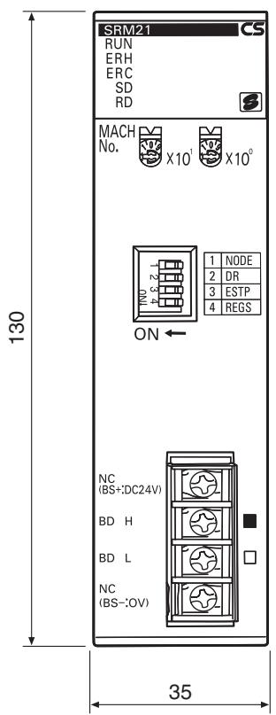
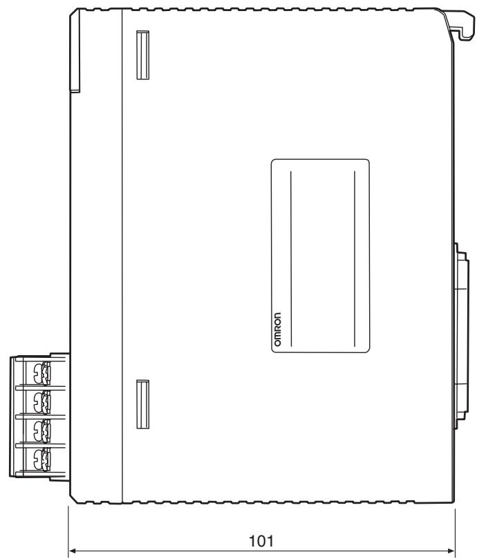
Refer to the CS-series PLC Operation Manual for installation dimensions of the CS1W-SRM21 when it is mounted on a Backplane.
Part Names and Functions
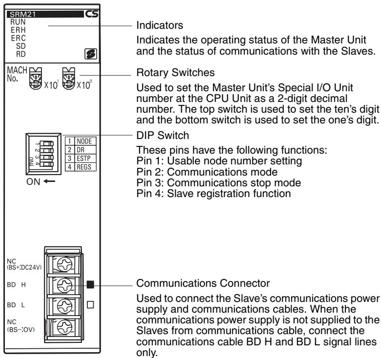
Indicators
The following table shows the meaning of the indicators.
| Indicator | Status | Meaning |
| RUN (green) | ON | The Unit is operating normally. |
| OFF | Indicates one of the following conditions (the ERH and ERC indicators light when errors other than the following errors occur): Power is not turned ON, watchdog timer error, etc. | |
| ERH (red) | ON | Indicates one of the following conditions: Errors occurring at the CPU Unit, such as Special I/O Unit number setting error. |
| OFF | The Unit is exchanging data with the CPU Unit normally. | |
| ERC (red) | ON | Indicates one of the following conditions: Master Unit internal error, communications error, or verification error |
| OFF | The Slaves are communicating normally. | |
| SD (yellow) | ON | Data is being transmitted. |
| OFF | Data is not being transmitted. | |
| RD (yellow) | ON | Data is being received. |
| OFF | Data is not being received. |
4-2-2 Switch Settings
Rotary Switches
The rotary switches are used to set the Master Unit's Special I/O Unit number as a decimal number.

The range of usable node number settings (set using pin 1 of the DIP switch) are listed in the following table.
| DIP switch pin 1 (NODE) | Usable node number setting | Unit number setting range |
| OFF | IN0 to IN7 and OUT0 to OUT7 (When using the words for one Special I/O Unit (10 words)) | 0 to 95 |
| ON | IN0 to IN15 and OUT0 to OUT15 (When using the words for two Special I/O Units (20 words)) | 0 to 94 |
Any unit number in the ranges above can be set, as long as the same unit number has not been set on another Special I/O Unit mounted in the PLC. Set the unit number with a small standard screwdriver; be careful not to damage the switch.
Caution Always turn the PLC OFF before changing the unit number setting.
- The Master Unit is shipped with the unit number set to 00.
- The unit number setting determines which words in the PLC's Special I/O Unit Area and DM Area are allocated to the Master Unit. Refer to 4-2-3 I/O Allocations for details.
- When the usable node number setting is set to IN0 to IN15 and OUT0 to OUT15, the CompoBus/S Master Unit is allocated twice as many words in the PLC's Special I/O Unit Area (the words for unit number set on the Master and the next unit number). The Master's unit number and the next unit number cannot be used by another Special I/O Unit mounted to the PLC.
- If the same unit number is used for the Master and another Special I/O Unit, an I/O UNIT OVER error will occur in the PLC and it will not be possible to start up the CompoBus/S System.
DIP Switch
The DIP switch is used to set the range of usable node numbers of Slaves, the communications mode, communications stop mode, and Slave registration function.
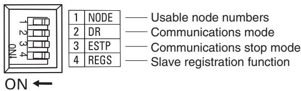
Note 1. Always turn the PLC OFF before changing the settings.
- DIP switch pins 1 to 4 are all set to OFF at the factory.
Set pin 1 (NODE) of the DIP switch as shown in the following table.
| Pin 1 setting | Usable node number setting | Maximum I/O points | Words allocated in the Special I/O Unit Area |
| OFF | IN0 to IN7 and OUT0 to OUT7 (up to 16 nodes can be connected) | 128 points (64 inputs, 64 outputs) | 10 words (words for one unit) Input/output data: 4 input words and 4 output words Status information: 2 words |
| ON | IN0 to IN15 and OUT0 to OUT15 (up to 32 nodes can be connected) | 256 points (128 inputs, 128 outputs) | 20 words (words for two units) Input/output data: 8 input words and 8 output words Status information: 4 words |
Note
- The usable node number setting determines the total number of words allocated, and combined with the DIP switch pin 2 setting, determines the Slaves' communication cycle. Refer to 4-2-3 I/O Allocations for details.
- When the usable node number setting is set to IN0 to IN15 and OUT0 to OUT15, the CompoBus/S Master Unit is allocated twice as many words in the PLC's Special I/O Unit Area (the words for unit number set on the Master and the next unit number). The Master's unit number and the next unit number cannot be used by another Special I/O Unit mounted to the PLC.
Set pin 2 (DR) of the DIP switch as shown in the following table.
| Pin 2 setting | Communications mode setting | Communications distance | Communications baud rate | Communications cycle time |
| OFF | High-speed Communications Mode | 100 m max. | 750 kbps | 0.5 ms (pin 1 OFF) or 0.8 ms (pin 1 ON) |
| ON | Long-distance Communications Mode | 500 m max. | 93.75 kbps | 4.0 ms (pin 1 OFF) or 6.0 ms (pin 1 ON) |
Note
- The communications mode of the Master Unit must match that of all Slaves. If the CompoBus/S System contains a Slave whose communications mode does not agree with that of the Master Unit, the COMM indicator on that Slave will not light, and normal communications with that Slave will not be possible. Other Slaves will not be adversely affected. (In such cases, the COMM indicator on the Master Unit will light normally.) For information on the Master Unit indicator statuses, refer to 6-3 Checking Operations of CS-series and CJ-series Master Units.
- The setting of pin 2 determines the communications distance, baud rate, and cycle time as shown in the above table.
Set pin 3 of the DIP switch as shown in the following table.
| Pin 3 setting | Communications stop mode setting |
| OFF | Communications mode Continues remote I/O communications when a communica- tions error occurs. |
| ON | Communications stop mode Stops remote I/O communications when a communications error occurs. |
If communications stop mode is set, communications automatically stop when a remote I/O communications error occurs, thereby preventing system malfunctions.
Note If the communications stop mode causes remote I/O communications to stop, communications will not restart when the cause of the error is removed. Turn ON the power again or restart the Unit to resume communications. Refer to 4-2-4 Slave Registration Function and Communications Stop Mode.
Set pin 4 (REGS) of the DIP switch as shown in the following table.
| Pin 4 setting | Slave registration function setting |
| OFF | Slave registration function setting disabled |
| ON | Slave registration function setting enabled |
The Slave registration function monitors Slaves that are joined in the network, and those unregistered Slaves that are illegally joined to the network, based on Slave information registered in the Slave registration tables (Special I/O Unit DM Area). Refer to 4-2-4 Slave Registration Function and Communications Stop Mode.
Note Set the Slave registration tables in the Special I/O Unit DM Area when using the Slave registration function. Refer to 4-2-4 Slave Registration Function and Communications Stop Mode.
4-2-3 I/O Allocations
Allocations and Master Unit Settings
CS-series Master Units are allocated words for Slave I/O data and status flags in the Special I/O Unit Area of the Master. Words in the Special I/O Unit DM Area is allocated for the Slave registration function and communications stop mode.
The areas used by the Master Unit depend on the Master Unit settings, as shown in the following table.
| Setting at Master Unit | Status | Affect on allocation |
| Usable node number settings (DIP switch pin 1) | OFF | Uses 10 words (words for one unit) from the Special I/O Unit Area as follows: Output: 4 words, input: 4 words, status: 2 words. (100 words are allocated in the Special I/O Unit DM Area) |
| ON | Uses 20 words (words for two units) from the Special I/O Unit Area as follows: Output: 8 words, input: 8 words, status: 4 words. (100 words are allocated in the Special I/O Unit DM Area) | |
| Special I/O Unit number setting (rotary switch) | n | First word of the area used in the Special I/O Unit Area is CIO 2000 + (n×10) words First word of the area used in the Special I/O Unit DM Area is D20000 + (n×100) words |
Slave Allocations
Slaves are allocated in the Special I/O Unit Area as shown in the following diagram. In CompoBus/S Systems, node numbers of Input Slaves and Output Slaves are treated separately so the same number can be allocated.
I/O Allocations when Pin 1 Is OFF
When pin 1 is OFF and node addresses IN0 to IN7 and OUT0 to OUT7 (64 inputs/64 outputs max) are used, words are allocated to the Slaves for each node number as shown in the following diagram.
Special I/O Unit Area in Master PLC
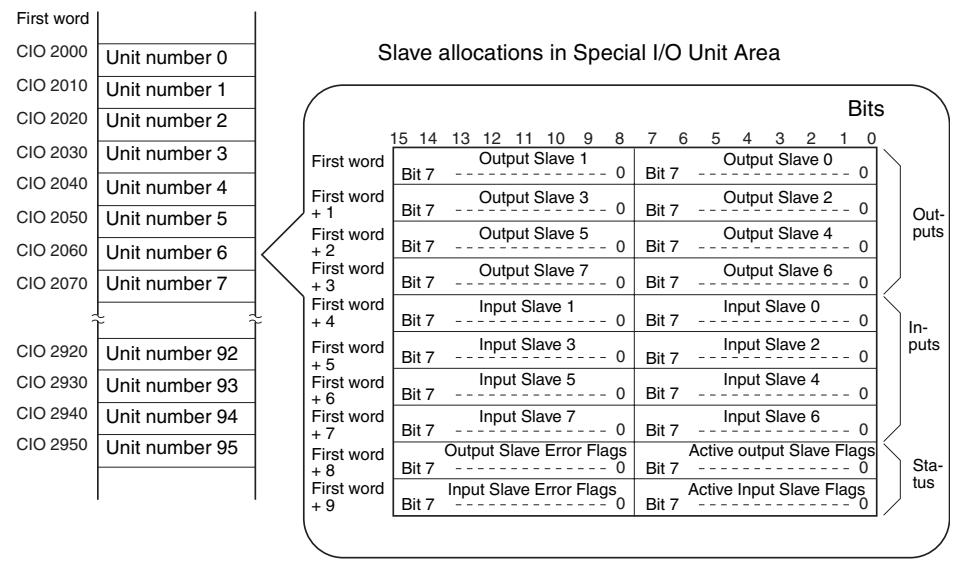
I/O Allocations when Pin 1 is ON
When pin 1 is ON and node addresses IN0 to IN15 and OUT0 to OUT15 (up to 128 inputs/128 outputs) are used, words are allocated to the Slaves for each node number as shown in the following diagram.
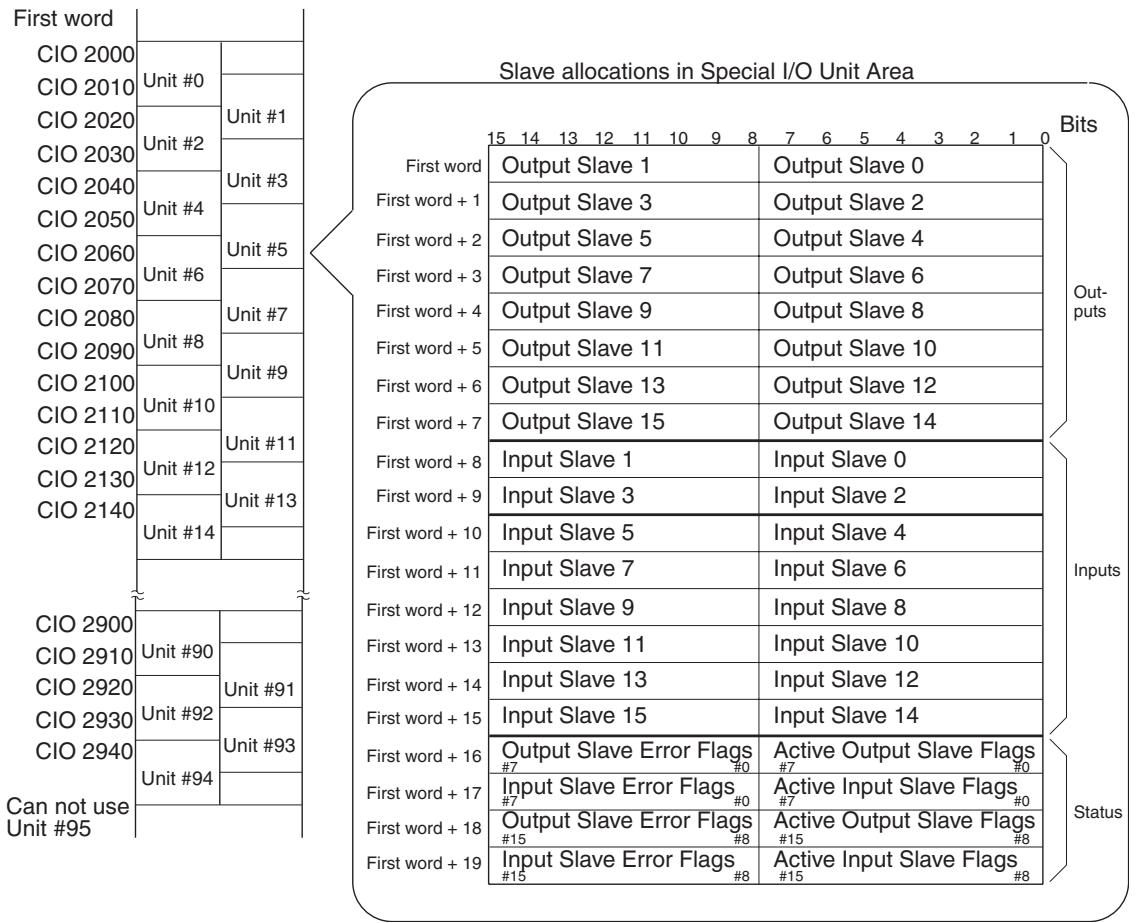
Special I/O Unit Area in Master PLC
Slave I/O and Corresponding Areas
Slave with 8 Inputs or 8 Outputs
The Slave is treated as one node number for output or input.
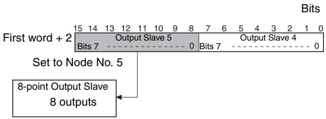
Slave with 16 Inputs or 16 Outputs
The Slave is treated as two node numbers for output or input, and allocated in the same words as follows:
- When an odd node number has been set:
Uses node number setting – 1 and node number setting
- When an even node number has been set:
Uses node number setting and node number setting +1
Example: When a 16-point Output Slave set as node number 5, the areas for Output Slaves 4 and 5 are used. Other Output Slaves cannot use the area allocated for Output Slave 4.
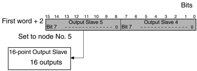
Slave with Mixed I/O (8 Inputs and 8 Outputs)
Slaves that have both outputs and inputs are also assigned a single node number, so the same node number is used for both outputs and inputs.
Example: When a Slave with 8 inputs and 8 outputs set as node number 2, the area for node number 2 outputs and inputs is used.
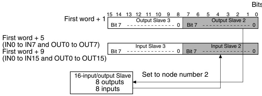
Slave with 4 Outputs or 4 Inputs
The Slave is treated as one node number for output or input. The Slave uses the rightmost 4 bits only, however, of the area allocated for one node number. (The leftmost 4 bits cannot be used by another Slave.)
- When an odd node number has been set:
Bits 8 to 11 are used and bits 12 to 15 are not used.
- When an even node number has been set:
Bits 0 to 3 are used and bits 4 to 7 are not used.
Example: When a Slave with 4 inputs is set as node number 7, the Slave is allocated the rightmost 4 bits (bits 8 to 11) in the area assigned for input node number 7.
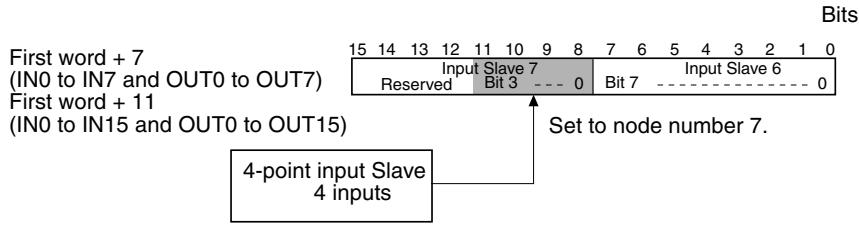
Slave with Mixed I/O (4 Outputs and 4 Inputs)
Slaves that have both outputs and inputs are also assigned a single node number, so the same node number is used for both outputs and inputs. The Slave uses the rightmost 4 bits only, however, of the area allocated for one node number. (The leftmost 4 bits cannot be used by another Slave.)
- When an odd node number has been set:
Bits 8 to 11 are used and bits 12 to 15 are not used.
- When an even node number has been set:
Bits 0 to 3 are used and bits 4 to 7 are not used.
Example: When a Slave with 4 outputs and 4 inputs is set to node number 2, the rightmost 4 bits (bits 0 to 3) of the area for node number 2 for both output and input are used.
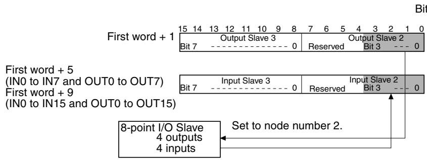
Slave with 32 Outputs or 32 Inputs
The Slave is treated as four node numbers for output or input and is allocated 2 consecutive words, as follows:
- When an odd node number has been set:
Uses (node number setting - 1) to (node number setting + 2) - When an even node number has been set:
Uses (node number setting) to (node number setting + 3).
Example: When a Slave with 32 outputs is set to node number 1, it uses the area assigned for Output Slave 0 to Output Slave 3. The area for Output Slave 0, 2, and 3 cannot be used for another Output Slave.
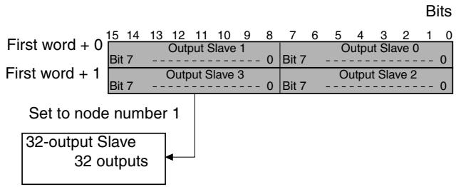
Slave with Mixed I/O (16 Outputs and 16 Inputs)
Slaves that have both outputs and inputs are also assigned a single node number, so the same node number is used for both outputs and inputs, and each is regarded as two node numbers. Outputs and inputs are allocated to the same words, as follows:
- When an odd node number has been set:
Uses (node number setting - 1) and (node number setting) - When an even node number has been set:
Uses (node number setting) and (node number setting + 1). - Example: When a Slave with 16 inputs and 16 outputs is set to node number 3, it uses Output Slave 2 and 3, and Input Slave 2 and 3. Output Slave 2 and Input Slave 2 cannot be used by other Slaves.
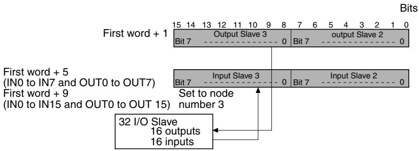
Using an Analog Terminal
An Analog Terminal uses 16, 32, 48, or 64 points. I/O allocations are shown in the following table.
| Number of points allocated | Node number setting | Node numbers used |
| 64 pointsSRT2-AD04: 4 inputs | Odd number | Node number setting - 1 to node number setting + 6 |
| Even number | Node number setting to node number setting + 7 | |
| 48 pointsSRT2-AD04: 3 inputs | Odd number | Node number setting - 1 to node number setting + 4 |
| Even number | Node number setting to node number setting + 5 | |
| 32 pointsSRT2-AD04: 2 inputsSRT2-DA02: 2 outputs | Odd number | Node number setting - 1 to node number setting + 2 |
| Even number | Node number setting to node number setting + 3 | |
| 16 pointsSRT2-AD04: 1 inputSRT2-DA02: 1 output | Odd number | Node number setting - 1 to node number setting |
| Even number | Node number setting to node number setting + 1 |
Do not use words for the node number outside the words allocated in the Master Unit. If words outside the specified output or input areas are used, the Unit cannot participate in communications and the COMM indicator will not turn ON.
Status Flag Functions
The functions of the flags in the status area are described below.
Active Output Slave Flags
These flags indicate which Output Slaves (0 to 15) are active nodes in the system. When the corresponding flag is ON, the Slave is an active node. All of these flags are reset when the power is turned ON or operation is restarted.
0 (OFF): No communications participation
The node hasn't participated in communications even once.
1 (ON): Communications participation
The flag won't change even if the node is withdrawn from the system.
Active Input Slave Flags
These flags indicate which Input Slaves (0 to 15) are active nodes in the system. When the corresponding flag is ON, the Slave is an active node. All of these flags are reset when the power is turned ON or operation is restarted.
0 (OFF): No communications participation
The node hasn't participated in communications even once.
1 (ON): Communications participation
The flag won't change even if the node is withdrawn from the system.
- Output Slave Error Flags
These flags indicate the communications status of the Output Slaves (0 to 15). All of these flags are reset when the power is turned ON or operation is restarted.
0 (OFF): Communications normal or inactive node
1 (ON): Withdrawn from communications (communications error)
- Input Slave Error Flags
These flags indicate the communications status of the Input Slaves (0 to 15). All of these flags are reset when the power is turned ON or operation is restarted.
0 (OFF): Communications normal or inactive node
1 (ON): Withdrawn from communications (communications error)
Note
- When the CompoBus/S System starts up, inputs from Input Slaves and outputs to Output Slaves become effective when the Active Slave Flag for the Slave is turned ON. It is recommended to write a ladder program that verifies that the Slave's Active Slave Flag is ON and its Error Flag is OFF before transmitting or receiving I/O data.
- When CS-series Master Units are set to communications stop mode, communications will stop when the Output Slave Error Flag or Input Slave Error Flag will turn ON. (Refer to 4-2-4 Slave Registration Function and Communications Stop Mode.)
4-2-4 Slave Registration Function and Communications Stop Mode
The CS-series Master Units now support a Slave registration function and communications stop mode. This new capability enables the CompoBus/S System to deliver increased reliability.
Slave Registration Function
The words allocated in the DM Area to the Master Unit as a Special I/O Unit contains a Slave registration table. By registering the Slaves that are normally participating in communications, the Slaves that are not joined to the network or are slow to join, or unregistered Slaves that are illegally joined can be monitored.
This function prevents system malfunctions due to incorrect wiring on site. The Slave registration function is enabled by turning ON pin 4 of the DIP switch on the Master Unit.
Communications Stop Mode
By setting communications stop mode, remote I/O communications will stop when a communications error occurs, and information on the Slave with the communications error is stored in the Special I/O Unit DM Area.
This function prevents the System from running on incorrect I/O data without having to disconnect a Slave with a communications error, and enables quick troubleshooting of the communications error.
When remote I/O communications are stopped in communications stop mode, they will not resume when the cause of the error is removed. To restart remote I/O communications, turn ON the power again, or restart the Unit. When the Unit is set to standard communications mode, even if a communications error occurs, the remote I/O communications will continue with the Slave with the error disconnected. Also, the Slave with the communications error is not
recorded in the Special I/O Unit DM Area, so a standard status area check using the program is required.
If a verification error occurs while using the Slave registration function, as it is not a communications error, remote I/O communications will continue even if communications stop mode is enabled.
Communications stop mode is set using pin 3 of the DIP switch on the Master Unit. (pin 3 ON: communications stop mode, pin 3 OFF: normal communications mode)
Words Allocated for Slave Registration and Communications Stop Mode
The words used for the Slave registration function and communications stop mode are allocated in the Special I/O Unit DM Area according to the Master Unit's Special I/O Unit number, as shown below.
First word = D20000 + (unit number × 100
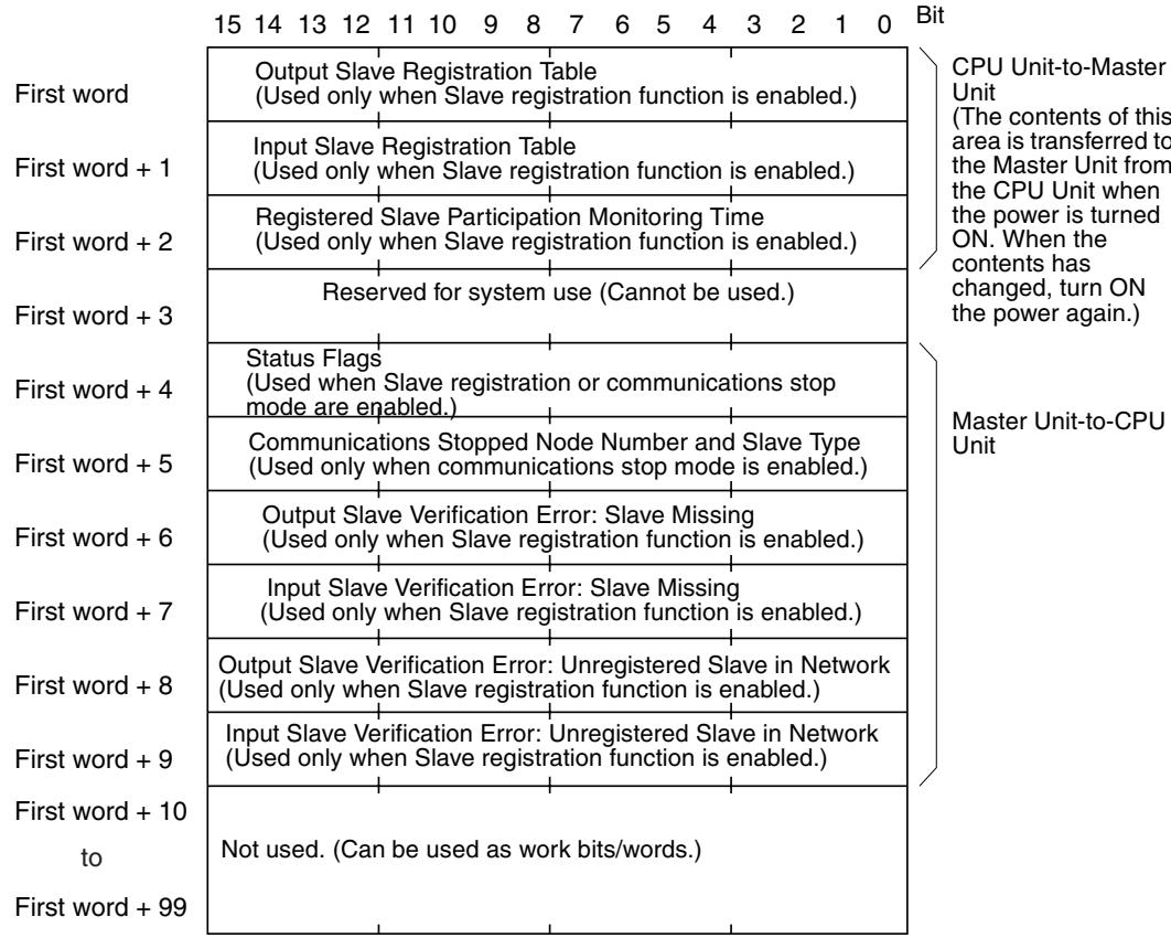
The contents from the first word to the first word +9 cannot be used for any other purpose. They can be used, however, if the Slave registration function and communications stop mode are not enabled.
The functions of each area are given in the following table.
| Word | Bit | Name | Function | ||
| +0 | 00 | Output Slave Regis-tration Table | OUT0 | Registers a list of the Output Slaves that are normally oper-ating in the network. This list is used for checking the Slaves with the Slave registration func-tion. Bits 00 to 15 correspond to Slave node numbers 0 to 15. The Output Slave is registered by turning ON its correspond-ing bit. | The bits in the Special I/O Unit Area must be registered to cor-respond to the node numbers actually used by the Slaves. Therefore, for Slaves with 16 points or higher, turn ON the bits for the other node numbers too. For example, the two consecutive bits used by a 16-point Slave or the four consecutive bits used by a 32-point Slave must be set. |
| 01 | OUT1 | ||||
| 02 | OUT2 | ||||
| to | to | ||||
| 13 | OUT13 | ||||
| 14 | OUT14 | ||||
| 15 | OUT15 | ||||
| +1 | 00 | Input Slave Registra-tion table | IN0 | Registers a list of the Input Slaves that are normally oper-ating in the network. This list is used to check the Slaves with the Slave registration function. Bits 00 to 15 correspond to Slave node numbers 0 to 15. The Input Slave is registered by turning ON its corresponding bit. | |
| 01 | IN1 | ||||
| 02 | IN2 | ||||
| to | to | ||||
| 13 | IN13 | ||||
| 14 | IN14 | ||||
| 15 | IN15 | ||||
| +2 | 00 to 15 | Registered Slave Par-ticipation Monitoring Time | The waiting time between when the Master Unit is started until the Slaves start to be checked using the Slave registration function. The time is set in increments of 1 ms as a hexadecimal. The setting range is 0000 (default is 2000 ms) or 0001 to FFDC (1 to 65500 ms). If the monitoring time lapses and there are still registered Slaves not joined in the network, a verification error (Slave missing) will occur. | ||
| +3 | 00 to 15 | Reserved for system use. | |||
| Word | Bit | Name | Function | ||
| +4 | 00 | Registration Com-pleted Flag | This flag is turned ON when all registered Slaves have joined the network. If all the registered Slaves have joined the network within the registered Slave participation monitoring time this flag will turn ON even if unregistered Slaves have also joined. The flag will not turn ON, however, if there are no Slaves set in the Slave registration table. The flag will remain ON until the power is turned OFF and ON again or the Unit is restarted. | ||
| 00 to 07 | Reserved for system use. | ||||
| 08 | Verification Error Flag: Slave Missing | This flag is turned ON under the following conditions. Registered Slaves do not join the network within the registered Slave participation monitoring time. When the Slave that caused the verification error is joined in the network, the flag will automatically be turned OFF. Check which Slave caused the error in the bit for verification error (Slave missing) in Output Slave (first word + 6) or verification error (Slave missing) in Input Slave (first word + 7). | |||
| 09 | Verification Error Flag: Unregistered Slave in Network | This flag is turned ON when an unregistered Slave has joined the network. The flag will remain ON until the power is turned OFF and ON again or the Unit is restarted, even if the Slave that caused the verification error is removed from the network. Check which Slave caused the error in the bit for Output Slave verification error (unregistered Slave in network) (first word + 8) or Input Slave verification error (unregistered Slave in network) (first word + 9). | |||
| 10 | Communications Stopped Flag | This flag is turned ON when the Master Unit is set to communications stop mode and remote I/O communications stop due to a communications error.. Once the flag has turned ON, the status remains until the power is turned OFF and ON again or the Unit is restarted. Check which Slave caused the error in the bits for communications stopped node number (bits 00 to 07 of first word + 5) and communications stopped Slave type (bit 15 of first word + 5). | |||
| 11 to 14 | Reserved for system use. | ||||
| 15 | Error Flag | This flag is turned ON when any of the bits 08 to 10 are set to1(ON). The flag is automatically turned OFF when all the bits 08 to 10 are turned OFF. | |||
| +5 | 00 to 07 | Communications Stopped Node Num-ber | When the Master Unit is set to communications stop mode and remote I/O communications stop due to a communications error, the node number of the Slave that caused the error is stored as a 2-digit hexadecimal (00 to 0F: 1 to 15). Check the Slave type (Output or Input) in the word for communications stopped Slave type (bit 15 of first word + 5). The node address stored will be held until the power is turned OFF and ON again or the Unit is restarted. | ||
| 08 to 14 | Reserved for system use. | ||||
| 15 | Communications Stopped Slave type | When the Master Unit is set to communications stop mode and remote I/O communications stop due to a communications error, the Slave type of the Slave that caused the error is stored as follows: 0 (OFF): Output Slave 1 (ON): Input Slave Check which Slave caused the error in the bits for communications stopped node number (bits 00 to 07 of first word + 5) When communications have stopped, the bit status is held until the power is turned OFF and ON again or the Unit is restarted. | |||
| Word | Bit | Name | Function | ||
| +6 | 00 | Output Slave Verification Error: Slave Missing | OUT0 | When the Slave registration function is enabled, the bit corresponding to the node number of the Output Slave that caused the verification error (Slave missing) will be turned ON. Bits 00 to 15 correspond to Output Slave node numbers 1 to 15. When the Slave that caused the verification error joins the network, the bit will automatically turned OFF. | The bits in the Special I/O Unit Area correspond to the node numbers actually used by the Slaves. Therefore, for Slaves with 16 points or higher, the bits other than those set for the node number may also be turned ON. For example, the two consecutive bits used by a 16-point Slave or the four consecutive bits used by a 32-point Slave may be turned ON at the same time. |
| 01 | OUT1 | ||||
| 02 | OUT2 | ||||
| to | to | ||||
| 13 | OUT13 | ||||
| 14 | OUT14 | ||||
| 15 | OUT15 | ||||
| +7 | 00 | Input Slave Verification Error: Slave Missing | IN0 | When the Slave registration function is enabled, the bit corresponding to the node number of the Input Slave that caused the verification error (Slave missing) will be turned ON. Bits 00 to 15 correspond to Input Slave node numbers 1 to 15. When the Slave that caused the verification error joins the network, the bit will automatically turned OFF. | |
| 01 | IN1 | ||||
| 02 | IN2 | ||||
| to | to | ||||
| 13 | IN13 | ||||
| 14 | IN14 | ||||
| 15 | IN15 | ||||
| +8 | 00 | Output Slave Verification Error: Unregistered Slave in Network | OUT0 | When the Slave registration function is enabled, the bit corresponding to the node number of the Output Slave where a verification error (unregistered Slave in network) will be turned ON. Bits 00 to 15 correspond to Output Slave node numbers 1 to 15. Once a bit has been turned ON the status will be held until the power is turned OFF and ON again or the Unit is restarted. | |
| 01 | OUT1 | ||||
| 02 | OUT2 | ||||
| to | to | ||||
| 13 | OUT13 | ||||
| 14 | OUT14 | ||||
| 15 | OUT15 | ||||
| +9 | 00 | Input Slave Verification Error: Unregistered Slave in Network | IN0 | When the Slave registration function is enabled, the bit corresponding to the node number of the Input Slave where a verification error (unregistered Slave in network) will be turned ON. Bits 00 to 15 correspond to Input Slave node numbers 1 to 15. Once a bit has been turned ON the status will be held until the power is turned OFF and ON again or the Unit is restarted. | |
| 01 | IN1 | ||||
| 02 | IN2 | ||||
| to | to | ||||
| 13 | IN13 | ||||
| 14 | IN14 | ||||
| 15 | IN15 | ||||
Slave Registration Function Procedure
When the Slave registration function is used, the Output/Input Slave registration table and registered Slave participation monitoring time must be set in the Special I/O Unit DM Area, but the power must be turned OFF and ON again or the Unit restarted to enable the settings.
The following example shows the procedure for using the Slave registration function. (Information on other Slave registration function settings and connections are omitted here.)
1,2,3... 1. Turn OFF pin 4 of the DIP switch on the Master Unit to disable the Slave registration function.
- Turn ON the power to the CPU Unit to which the Master Unit is mounted.
-
Use a Programming Device for the CPU Unit to set the following information in the Special I/O Unit DM Area words used by the Master Unit.
-
Output Slave registration table
- Input Slave registration table
-
Registration Slave participation monitoring time
-
Turn OFF the power to the CPU Unit to which the Master Unit is mounted.
- Turn ON pin 4 of the DIP switch on the Master Unit to enable the Slave registration function
- Turn ON the power to the CPU Unit to which the Master Unit is mounted or restart the Master Unit.
The settings in the Special I/O Unit DM Area can be set while pin 4 of the DIP switch on the Master Unit is set to ON, but a verification error may occur due to the incorrectly set Slave registration table.
4-2-5 Allocations for Master Unit in PLC
The following table shows the words in the CPU Unit that are related to the Master Unit.
| Data area | Bit(s) | Name | Function |
| Auxiliary Area (A) | A33000 to A33515 | Special I/O Unit Restarting Flags | These flags are turned ON while a Special I/O Unit is restarting. Each bit corresponds to the Unit with the same unit number. |
| A40113 | Dual Number Use Error Flag (Fatal Error) | This flag is turned ON in the following situations: When the same unit number has been set on more than one CS1 CPU Bus Unit. When the same unit number has been set on more than one Special I/O Unit. When the same word is allocated more than once for Basic I/O Units. | |
| A40206 | Special I/O Unit Error Flag | This flag is turned ON when the same unit number has been set on more than one Special I/O Unit, or when an error has occurred during data transfer between the PLC and the Special I/O Unit. The unit number of the Unit is written to word A418. | |
| A41100 to A41615 | Special I/O Unit Number Duplication Flags | These flags are turned ON when the same unit number has been set on more than one Special I/O Unit (i.e., when A40113 is ON). Each bit corresponds to the Unit with the same unit number. | |
| A41800 to A42315 | Special I/O Unit Error Flags | These flags are turned ON when the same unit number has been set on more than one Special I/O Unit, or when an error has occurred during data transfer between the PLC and the Special I/O Unit. Each bit corresponds to the Unit with the same unit number. | |
| A50200 to A50715 | Special I/O Unit Restart Bits | Turn the corresponding bit ON and then OFF to restart a Special I/O Unit. Each bit corresponds to the Unit with the same unit number. | |
| PLC Setup | 22600 to 23115 | Special I/O Unit Refresh Disable Bits | Turn the corresponding bit ON to disable refreshing of the corresponding Special I/O Unit (except those on Slave Racks). |
4-3 CJ1W-SRM21 Master Unit for CJ-series PLCs
4-3-1 Specifications and Part Names
Specifications
General Specifications
General specifications conform to those of the CJ-series PLCs.
Performance Specifications
| Item | Specifications | |
| Model | CJ1W-SRM21 | |
| Unit classification | Special I/O Unit | |
| Internal current consumption | 5 V DC, 150 mA max. | |
| Allowable current from the Slave communications power supply connection terminals | 4 A (14 to 26.4 V DC) | |
| Weight | 66 g max. (including provided connector) | |
| Max. number of Masters | 40 Units | |
| Master Unit mounting location | Can be connected in the CJ-series CPU Rack or Expansion I/O Rack. | |
| Max. number of I/O points per Master | 256 points (128 inputs/128 outputs) | 128 points (64 inputs/64 outputs) |
| Number of points per node number | 8-point mode | |
| Number of usable node numbers per Master | INO to IN15 and OUT0 to OUT15 (up to 32 nodes can be connected) | INO to IN7 and OUT0 to OUT7 (up to 16 nodes can be connected) |
Dimensions
The following diagram shows the dimensions of the CJ1W-SRM21-V1 Master Unit. All dimensions are in mm.
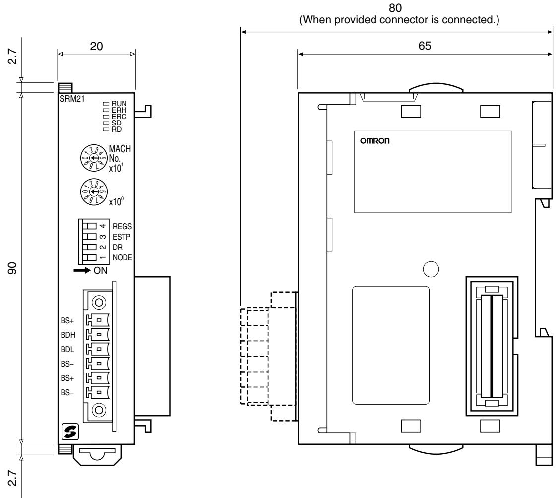
Refer to the CJ-series Operation Manual for details on installing the CJ1W-SRM21 when it is connected in a CJ-series CPU Rack or Expansion Rack.
Part Names and Functions
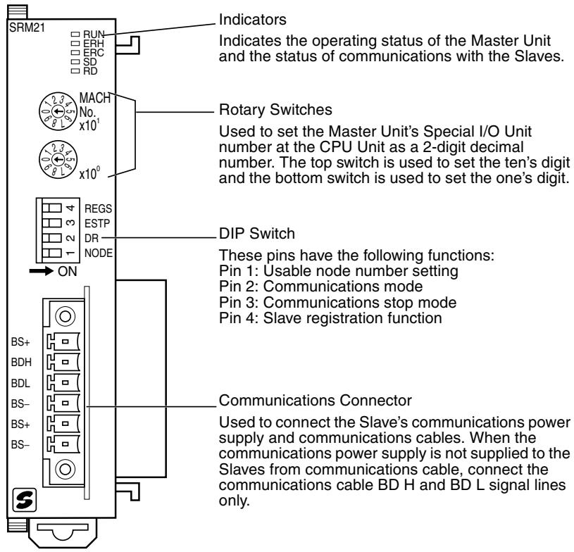
Indicators
The following table shows the meaning of the indicators.
| Indicator | Status | Meaning |
| RUN (green) | ON | The Unit is operating normally. |
| OFF | Indicates one of the following conditions (the ERH and ERC indicators light when errors other than the following errors occur): Power is not turned ON, watchdog timer error, etc. | |
| ERH (red) | ON | Indicates one of the following conditions: Errors occurring at the CPU Unit, such as Special I/O Unit number setting error. |
| OFF | The Unit is exchanging data with the CPU Unit normally. | |
| ERC (red) | ON | Indicates one of the following conditions: Master Unit internal error, communications error, or verification error |
| OFF | The Slaves are communicating normally. | |
| SD (yellow) | ON | Data is being transmitted. |
| OFF | Data is not being transmitted. | |
| RD (yellow) | ON | Data is being received. |
| OFF | Data is not being received. |
4-3-2 Switch Settings
Rotary Switches
The rotary switches are used to set the Master Unit's Special I/O Unit number as a decimal number.
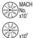
The range of usable node number settings (set using pin 1 of the DIP switch) are listed in the following table.
| DIP switch pin 1 (NODE) | Usable node number setting | Unit number setting range |
| OFF | IN0 to IN7 and OUT0 to OUT7 (When using the words for one Special I/O Unit (10 words)) | 0 to 95 |
| ON | IN0 to IN15 and OUT0 to OUT15 (When using the words for two Special I/O Units (20 words)) | 0 to 94 |
Any unit number in the ranges above can be set, as long as the same unit number has not been set on another Special I/O Unit mounted in the PLC. Set the unit number with a small standard screwdriver; be careful not to damage the switch.
Caution Always turn the PLC OFF before changing the unit number setting.
- The Master Unit is shipped with the unit number set to 00.
- The unit number setting determines which words in the PLC's Special I/O Unit Area and DM Area are allocated to the Master Unit. Refer to 4-1-3 I/O Allocations in CS-series, C200HX/C200HG/C200HE-(Z)E, and C200HS PLCs for details.
- When the usable node number setting is set to IN0 to IN15 and OUT0 to OUT15, the CompoBus/S Master Unit is allocated twice as many words in the PLC's Special I/O Unit Area (the words for unit number set on the Master and the next unit number). The Master's unit number and the next unit number cannot be used by another Special I/O Unit mounted to the PLC.
- If the same unit number is used for the Master and another Special I/O Unit, an I/O UNIT OVER error will occur in the PLC and it will not be possible to start up the CompoBus/S System.
DIP Switch
The DIP switch is used to set the range of usable node numbers of Slaves, the communications mode, communications stop mode, and Slave registration function.
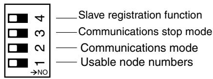
Note 1. Always turn the PLC OFF before changing the settings.
- DIP switch pins 1 to 4 are all set to OFF at the factory.
Set pin 1 (NODE) of the DIP switch as shown in the following table.
| Pin 1 setting | Usable node number setting | Maximum I/O points | Words allocated in the Special I/O Unit Area |
| OFF | IN0 to IN7 and OUT0 to OUT7 (up to 16 nodes can be connected) | 128 points (64 inputs, 64 outputs) | 10 words (words for one unit) Input/output data: 4 input words and 4 output words Status information: 2 words |
| ON | IN0 to IN15 and OUT0 to OUT15 (up to 32 nodes can be connected) | 256 points (128 inputs, 128 outputs) | 20 words (words for two units) Input/output data: 8 input words and 8 output words Status information: 4 words |
Note
- The usable node number setting determines the total number of words allocated, and combined with the DIP switch pin 2 setting, determines the Slaves' communication cycle. Refer to 4-1-3 I/O Allocations in CS-series, C200HX/C200HG/C200HE-(Z)E, and C200HS PLCs for details.
- When the usable node number setting is set to IN0 to IN15 and OUT0 to OUT15, the CompoBus/S Master Unit is allocated twice as many words in the PLC's Special I/O Unit Area (the words for unit number set on the Master and the next unit number). The Master's unit number and the next unit number cannot be used by another Special I/O Unit mounted to the PLC.
Set pin 2 (DR) of the DIP switch as shown in the following table.
| Pin 2 setting | Communications mode setting | Communications distance | Communications baud rate | Communications cycle time |
| OFF | High-speed Communications Mode | 100 m max. | 750 kbps | 0.5 ms (pin 1 OFF) or 0.8 ms (pin 1 ON) |
| ON | Long-distance Communications Mode | 500 m max. | 93.75 kbps | 4.0 ms (pin 1 OFF) or 6.0 ms (pin 1 ON) |
Note
- The communications mode of the Master Unit must match that of all Slaves. If the CompoBus/S System contains a Slave whose communications mode does not agree with that of the Master Unit, the COMM indicator on that Slave will not light, and normal communications with that Slave will not be possible. Other Slaves will not be adversely affected. (In such cases, the COMM indicator on the Master Unit will light normally.) For information on the Master Unit indicator statuses, refer to 6-3 Checking Operations of CS-series and CJ-series Master Units.
- The setting of pin 2 determines the communications distance, baud rate, and cycle time as shown in the above table.
Set pin 3 of the DIP switch as shown in the following table.
| Pin 3 setting | Communications stop mode setting |
| OFF | Communications mode Continues remote I/O communications when a communica- tions error occurs. |
| ON | Communications stop mode Stops remote I/O communications when a communications error occurs. |
If communications stop mode is set, communications automatically stop when a remote I/O communications error occurs, thereby preventing system malfunctions.
Note If the communications stop mode causes remote I/O communications to stop, communications will not restart when the cause of the error is removed. Turn ON the power again or restart the Unit to resume communications. Refer to 4-3-5 Slave Registration Function and Communications Stop Mode.
Set pin 4 (REGS) of the DIP switch as shown in the following table.
| Pin 4 setting | Slave registration function setting |
| OFF | Slave registration function setting disabled |
| ON | Slave registration function setting enabled |
The Slave registration function monitors Slaves that are joined in the network, and those unregistered Slaves that are illegally joined to the network, based on Slave information registered in the Slave registration tables (Special I/O Unit DM Area). Refer to 4-3-5 Slave Registration Function and Communications Stop Mode.
Note Set the Slave registration tables in the Special I/O Unit DM Area when using the Slave registration function. Refer to 4-3-5 Slave Registration Function and Communications Stop Mode.
4-3-3 Wiring and Installing Communications Cables
Communications Connector Wiring
Applicable Connectors
Use either of the following connectors when connecting CompoBus/S communications cable to a CJ-series Master Unit
| Manufacturer/Model | Appearance | Remarks |
| Phoenix Contact FK-MCP1.5/6-STF-3.81 | Screwless terminals (pro- vided with the CJ-series Master Unit) | |
| Phoenix Contact MC1.5/6-STF-3.81 | Screw terminals |
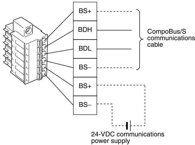
Communications Connector Pin Arrangement
Screwless Terminals
FK-MCP1.5/6-STF-3.81
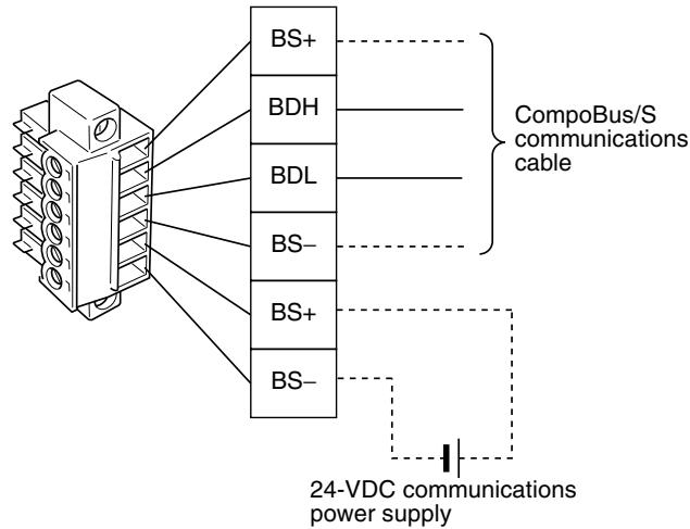
Screw Terminals
MC1.5/6-STF-3.81
The BS + and BS- terminals are internally connected.
The BS + and BS- terminals are used to supply communications power supply to the Slaves (they are not used for the Master Unit). When supplying communications power at the Slave, such as by using 2-conductor VCTF cable, connect the BD H and BD L terminals.
Note The signal wires for Special Flat Cable are shown in the following diagram. Special Flat Cable can be easily connected to CJ-series Master Units because the upper four pins of the communications connector have the same pin arrangement (Special Flat Cable signal wires are connected in order, with the communications power supply connected to the lower two pins.)
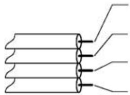
Communications power supply ^+ (BS + ) Brown
Communications data high (BD H) Black
Communications data low (BD L) White
Communications power supply - (BS-) Blue
Communications Cable Crimp Terminals
The following table shows the recommended crimp terminals for the signal wires connected to the communications connector. Use either of the following cable crimp terminals.
| Model | Manufacturer |
| AI-series AI0.75-8GY (product code 3200519) | Phoenix Contact |
| H0.75/14 (product code 046290) | Weidmuller Co., Ltd. |
Insert the cable into the crimp terminal and crimp the end section.
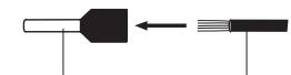
Sleeve
Crimp terminal Cable
Use the following crimping tools.
| Model | Manufacturer |
| UD6 (product code 1204436) or ZA3 Series | Phoenix Contact |
| PZ1.5 Crimper (product code 900599) | Weidmuller |
Preparing and Connecting Communications Cables
Use the following procedure to connect the communications data/communications power supply to the connector.
Note
- Always turn OFF the Master's power supply and communications power supply before connecting or disconnecting the communications data/communications power supply
- Use a dedicated communications connector.
Screwless Connector
Install the screwless communications connector in the Master Unit and then prepare as follows:
1,2,3...
- Remove sufficient (approx. 10mm ) insulation from the signal wires for a crimp terminal, and twist the exposed wire strands together tightly.
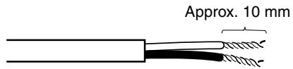
Note If using VCTF cable, cover the severed end of the insulation with vinyl tape or heat-shrinking tube.
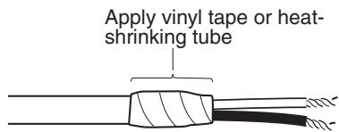
- After installing the crimp terminal to the stripped end of the signal wires, apply vinyl tape or heat-shrinking tube. The signal wires of the CJ-series Master Unit's communications connector can be connected without using crimp terminals.
Note Always use the specified crimping tool to install crimp terminals. When a crimping tool is not used, the terminal cannot be correctly crimped and may cause the cables to be disconnected.
- Check the direction of the connector and insert each of the signal wires securely into the back of the connector holes. (The signal wires are fixed, so a tool is not required to secure them.)
If crimp terminals are not installed on the signal wires, use a small flat
blade screwdriver to push down the orange tab on the connector and push in the signal wire.
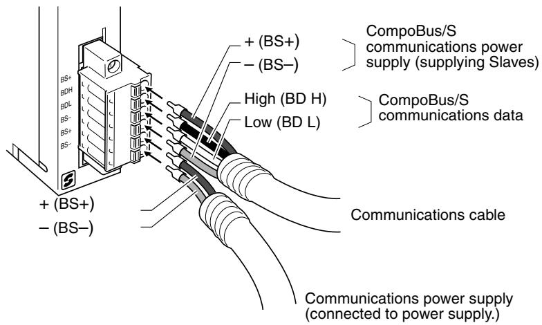
Note To disconnect the signal wires from a screwless connector, push down on the orange tab and at the same time pull out the signal wire. (The signal wires can be easily removed while leaving the communications connector installed in the Master Unit.)
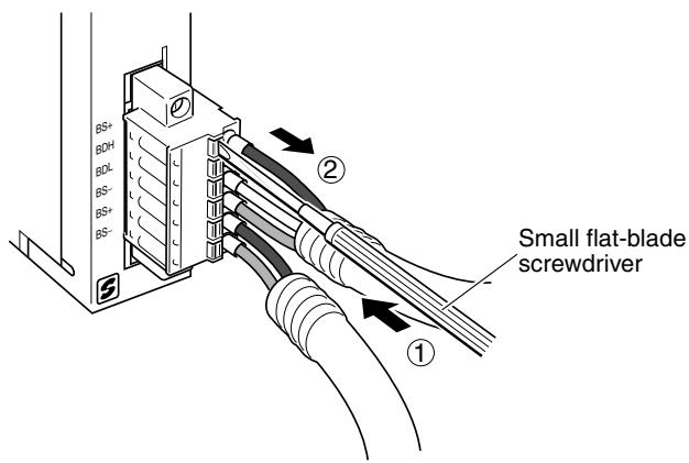
Check that the communications connector is securely fixed to the Master Unit. Tighten the communications connector to the specified tightening torque (0.25 to 0.3 N·m).
Connector with Screws
When using connectors with screws, remove the communications connector from the Master Unit and assemble the connector and cable according to the following procedure, as required. (If the Master Unit has sufficient space around it, the procedure can be followed while leaving the communications connector installed in the Master Unit.)
1,2,3... 1. Remove sufficient (approx. 10mm ) insulation from the signal wires for a crimp terminal, and twist the exposed wire strands together tightly.
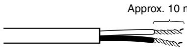
Note If using VCTF cable, cover the severed end of the insulation with vinyl tape or heat-shrinking tube.
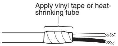
- After installing the crimp terminal to the stripped end of the signal wires, apply vinyl tape or heat-shrinking tube.
Note Always use the specified crimping tool to install crimp terminals. When a crimping tool is not used, the terminal cannot be correctly crimped and may cause the cables to be disconnected.
- Check the direction of the connector and insert each of the signal wires securely into the back of the connector holes.
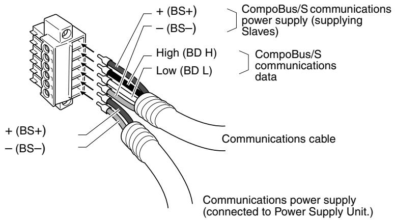
Note Before inserting the signal wires, check that the connector's lock screws are sufficiently loose. If the screws are not loose when the signal wires are inserted, the signal wires will enter the gap at the back of the connector rather than the side to be tightened and may not be secured.
- Tighten the signal wires securely using the connector's signal wire lock screws. A standard screwdriver that is only slim at the end cannot be inserted into the back of the screw hole, so use a small flat-blade screwdriver that is of uniform thickness. The tightening torque is 0.22 to 0.25N· m .
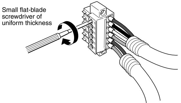
Note Use a precision flat-blade screwdriver and M2 size terminal screws for the communications connector.
- Connect the communications cable connector to the Master Unit, as shown in the following diagram.
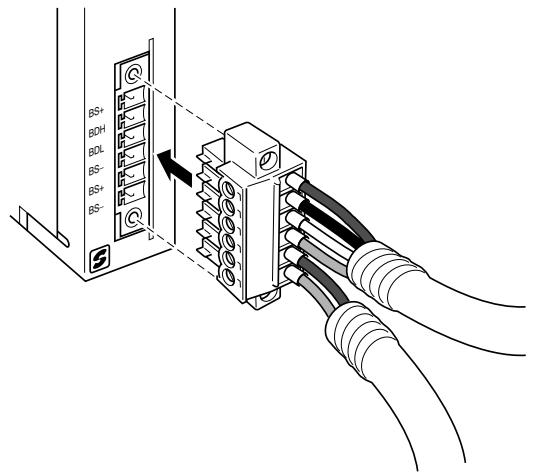
- Tighten the connector screws and secure the connector to the Master Unit. The tightening torque is 0.25 to 0.3N· m .
4-3-4 I/O Allocations
CJ-series Master Units are allocated words for Slave I/O data and status flags in the Special I/O Unit Area of the Master. Words in the Special I/O Unit DM Area is allocated for the Slave registration function and communications stop mode.
Allocations and Master Unit Settings
The areas used by the Master Unit depend on the Master Unit settings, as shown in the following table.
| Setting at Master Unit | Status | Affect on allocation |
| Usable node number settings (DIP switch pin 1) | OFF | Uses 10 words (words for one unit) from the Special I/O Unit Area as follows: Output: 4 words, input: 4 words, status: 2 words. (100 words are allocated in the Special I/O Unit DM Area) |
| ON | Uses 20 words (words for two units) from the Special I/O Unit Area as follows: Output: 8 words, input: 8 words, status: 4 words. (100 words are allocated in the Special I/O Unit DM Area) | |
| Special I/O Unit number setting (rotary switch) | n | First word of the area used in the Special I/O Unit Area is CIO 2000 + (n ×10) words First word of the area used in the Special I/O Unit DM Area is D20000 + (n×100) words |
Slave Allocations
Slaves are allocated in the Special I/O Unit Area as shown in the following diagram. In CompoBus/S Systems, node numbers of Input Slaves and Output Slaves are treated separately so the same number can be allocated.
I/O Allocations when Pin 1 Is OFF
When pin 1 is OFF and node addresses IN0 to IN7 and OUT0 to OUT7 (64 inputs/64 outputs max) are used, words are allocated to the Slaves for each node number as shown in the following diagram.
Special I/O Unit Area in Master PLC
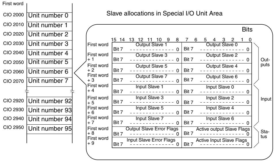
I/O Allocations when Pin 1 is ON
When pin 1 is ON and node addresses IN0 to IN15 and OUT0 to OUT15 (up to 128 inputs/128 outputs) are used, words are allocated to the Slaves for each node number as shown in the following diagram.
Special I/O Unit Area in Master PLC
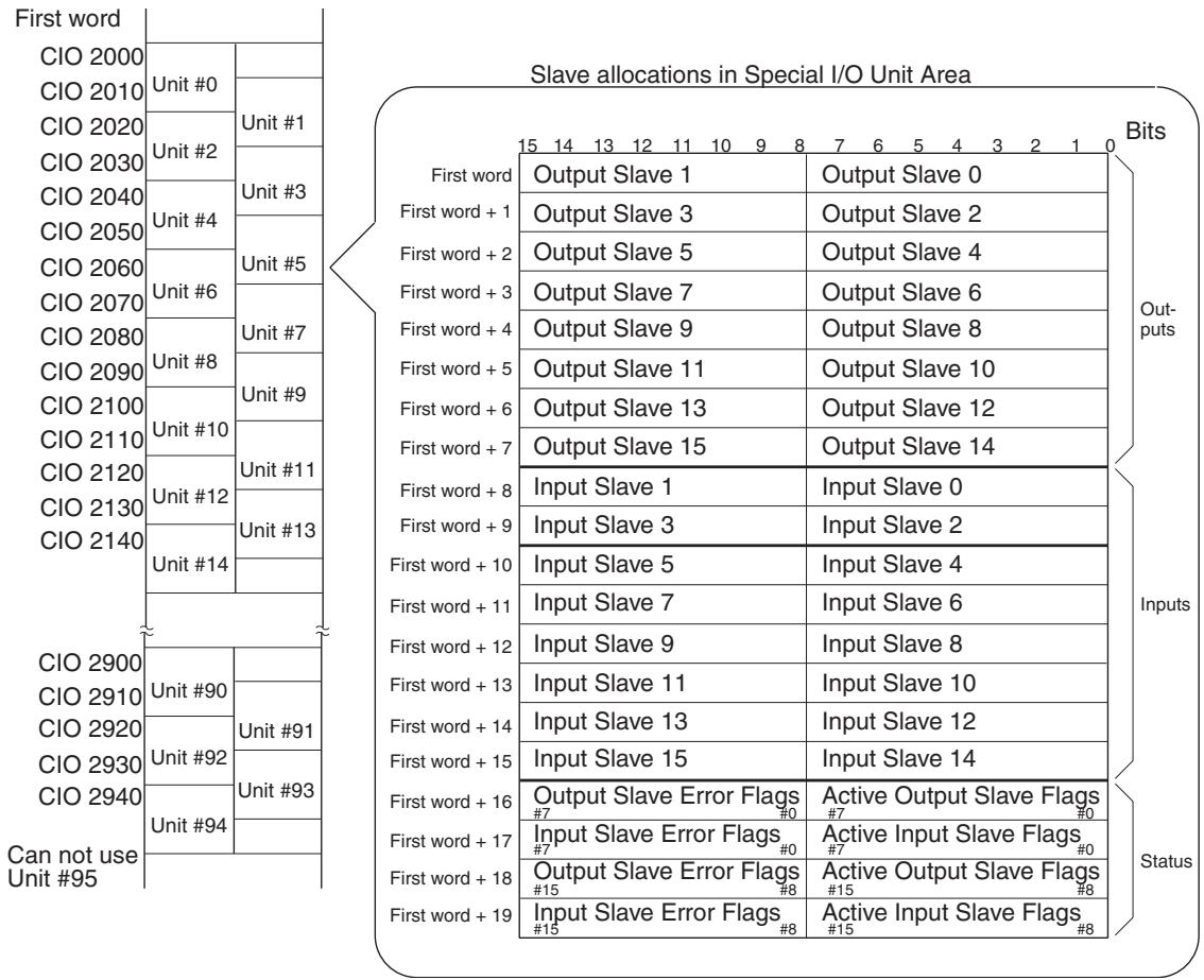
Slave I/O and Corresponding Areas
Slave with 8 Inputs or 8 Outputs
The Slave is treated as one node number for output or input.
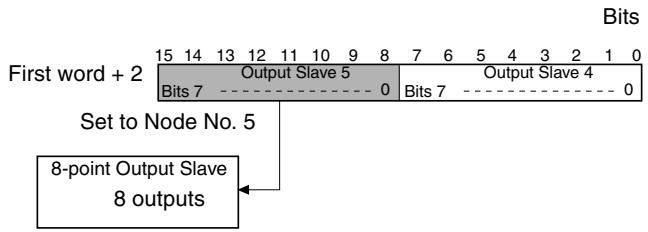
Slave with 16 Inputs or 16 Outputs
The Slave is treated as two node numbers for output or input, and allocated in the same words as follows:
- When an odd node number has been set:
Uses node number setting – 1 and node number setting
- When an even node number has been set:
Uses node number setting and node number setting +1
Example: When a 16-point Output Slave set as node number 5, the areas for Output Slaves 4 and 5 are used. Other Output Slaves cannot use the area allocated for Output Slave 4.
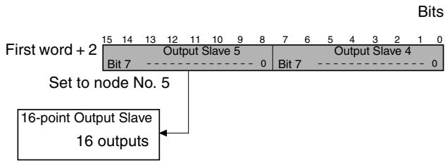
Slave with Mixed I/O (8 Inputs and 8 Outputs)
Slaves that have both outputs and inputs are also assigned a single node number, so the same node number is used for both outputs and inputs.
Example: When a Slave with 8 inputs and 8 outputs set as node number 2, the area for node number 2 outputs and inputs is used.
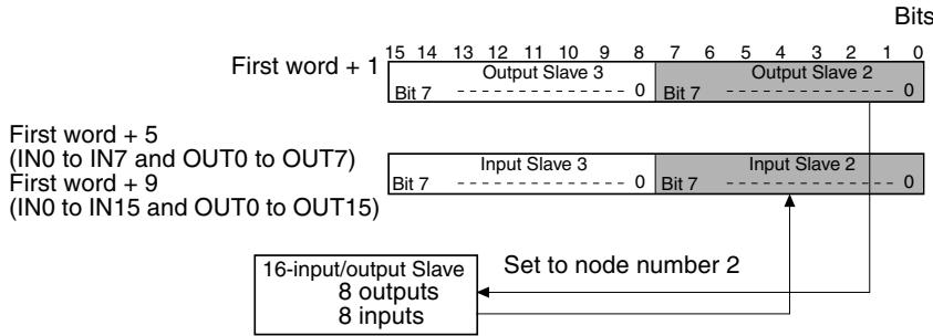
Slave with 4 Outputs or 4 Inputs
The Slave is treated as one node number for output or input. The Slave uses the rightmost 4 bits only, however, of the area allocated for one node number. (The leftmost 4 bits cannot be used by another Slave.)
- When an odd node number has been set:
Bits 8 to 11 are used and bits 12 to 15 are not used.
- When an even node number has been set:
Bits 0 to 3 are used and bits 4 to 7 are not used.
Example: When a Slave with 4 inputs is set as node number 7, the Slave is allocated the rightmost 4 bits (bits 8 to 11) in the area assigned for input node number 7.
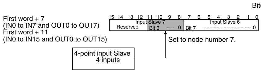
Slave with Mixed I/O (4 Outputs and 4 Inputs)
Slaves that have both outputs and inputs are also assigned a single node number, so the same node number is used for both outputs and inputs. The Slave uses the rightmost 4 bits only, however, of the area allocated for one node number. (The leftmost 4 bits cannot be used by another Slave.)
- When an odd node number has been set:
Bits 8 to 11 are used and bits 12 to 15 are not used.
- When an even node number has been set:
Bits 0 to 3 are used and bits 4 to 7 are not used.
Example: When a Slave with 4 outputs and 4 inputs is set to node number 2, the rightmost 4 bits (bits 0 to 3) of the area for node number 2 for both output and input are used.
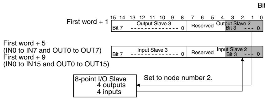
Slave with 32 Outputs or 32 Inputs
The Slave is treated as four node numbers for output or input and is allocated 2 consecutive words, as follows:
- When an odd node number has been set:
Uses (node number setting - 1) to (node number setting + 2)
- When an even node number has been set:
Uses (node number setting) to (node number setting + 3).
Example: When a Slave with 32 outputs is set to node number 1, it uses the area assigned for Output Slave 0 to Output Slave 3. The area for Output Slave 0, 2, and 3 cannot be used for another Output Slave.
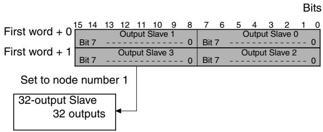
Slave with Mixed I/O (16 Outputs and 16 Inputs)
Slaves that have both outputs and inputs are also assigned a single node number, so the same node number is used for both outputs and inputs, and each is regarded as two node numbers. Outputs and inputs are allocated to the same words, as follows:
- When an odd node number has been set:
Uses (node number setting - 1) and (node number setting)
- When an even node number has been set:
Uses (node number setting) and (node number setting + 1).
- Example: When a Slave with 16 inputs and 16 outputs is set to node number 3, it uses Output Slave 2 and 3, and Input Slave 2 and 3. Output Slave 2 and Input Slave 2 cannot be used by other Slaves.
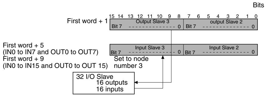
Using an Analog Terminal
An Analog Terminal uses 16, 32, 48, or 64 points. I/O allocations are shown in the following table.
| Number of points allocated | Node number setting | Node numbers used |
| 64 pointsSRT2-AD04: 4 inputs | Odd number | Node number setting - 1 to node number setting + 6 |
| Even number | Node number setting to node number setting + 7 | |
| 48 pointsSRT2-AD04: 3 inputs | Odd number | Node number setting - 1 to node number setting + 4 |
| Even number | Node number setting to node number setting + 5 | |
| 32 pointsSRT2-AD04: 2 inputsSRT2-DA02: 2 outputs | Odd number | Node number setting - 1 to node number setting + 2 |
| Even number | Node number setting to node number setting + 3 | |
| 16 pointsSRT2-AD04: 1 inputSRT2-DA02: 1 output | Odd number | Node number setting - 1 to node number setting |
| Even number | Node number setting to node number setting + 1 |
Do not use words for the node number outside the words allocated in the Master Unit. If words outside the specified output or input areas are used, the Unit cannot participate in communications and the COMM indicator will not turn ON.
Status Flag Functions
The functions of the flags in the status area are described below.
Active Output Slave Flags
These flags indicate which Output Slaves (0 to 15) are active nodes in the system. When the corresponding flag is ON, the Slave is an active node. All of these flags are reset when the power is turned ON or operation is restarted.
0 (OFF): No communications participation
The node hasn't participated in communications even once.
1 (ON): Communications participation
The flag won't change even if the node is withdrawn from the system.
Active Input Slave Flags
These flags indicate which Input Slaves (0 to 15) are active nodes in the system. When the corresponding flag is ON, the Slave is an active node. All of these flags are reset when the power is turned ON or operation is restarted.
0 (OFF): No communications participation
The node hasn't participated in communications even once.
1 (ON): Communications participation
The flag won't change even if the node is withdrawn from the system.
- Output Slave Error Flags
These flags indicate the communications status of the Output Slaves (0 to 15). All of these flags are reset when the power is turned ON or operation is restarted.
0 (OFF): Communications normal or inactive node
1 (ON): Withdrawn from communications (communications error)
- Input Slave Error Flags
These flags indicate the communications status of the Input Slaves (0 to 15). All of these flags are reset when the power is turned ON or operation is restarted.
0 (OFF): Communications normal or inactive node
1 (ON): Withdrawn from communications (communications error)
Note
- When the CompoBus/S System starts up, inputs from Input Slaves and outputs to Output Slaves become effective when the Active Slave Flag for the Slave is turned ON. It is recommended to write a ladder program that verifies that the Slave's Active Slave Flag is ON and its Error Flag is OFF before transmitting or receiving I/O data.
- When CJ-series Master Units are set to communications stop mode, communications will stop when the Output Slave Error Flag or Input Slave Error Flag will turn ON. (Refer to 4-3-5 Slave Registration Function and Communications Stop Mode.)
4-3-5 Slave Registration Function and Communications Stop Mode
The CJ-series Master Units now support a Slave registration function and communications stop mode. This new capability enables the CompoBus/S System to deliver increased reliability.
Slave Registration Function
The words allocated in the DM Area to the Master Unit as a Special I/O Unit contains a Slave registration table. By registering the Slaves that are normally participating in communications, the Slaves that are not joined to the network or are slow to join, or unregistered Slaves that are illegally joined can be monitored.
This function prevents system malfunctions due to incorrect wiring on site. The Slave registration function is enabled by turning ON pin 4 of the DIP switch on the Master Unit.
Communications Stop Mode
By setting communications stop mode, remote I/O communications will stop when a communications error occurs, and information on the Slave with the communications error is stored in the Special I/O Unit DM Area.
This function prevents the System from running on incorrect I/O data without having to disconnect a Slave with a communications error, and enables quick troubleshooting of the communications error.
When remote I/O communications are stopped in communications stop mode, they will not resume when the cause of the error is removed. To restart remote I/O communications, turn ON the power again, or restart the Unit. When the Unit is set to standard communications mode, even if a communications error occurs, the remote I/O communications will continue with the Slave with the error disconnected. Also, the Slave with the communications error is not
recorded in the Special I/O Unit DM Area, so a standard status area check using the program is required.
If a verification error occurs while using the Slave registration function, as it is not a communications error, remote I/O communications will continue even if communications stop mode is enabled.
Communications stop mode is set using pin 3 of the DIP switch on the Master Unit. (pin 3 ON: communications stop mode, pin 3 OFF: normal communications mode)
Words Allocated for Slave Registration and Communications Stop Mode
The words used for the Slave registration function and communications stop mode are allocated in the Special I/O Unit DM Area according to the Master Unit's Special I/O Unit number, as shown below.
First word = D20000 + (unit number × 100
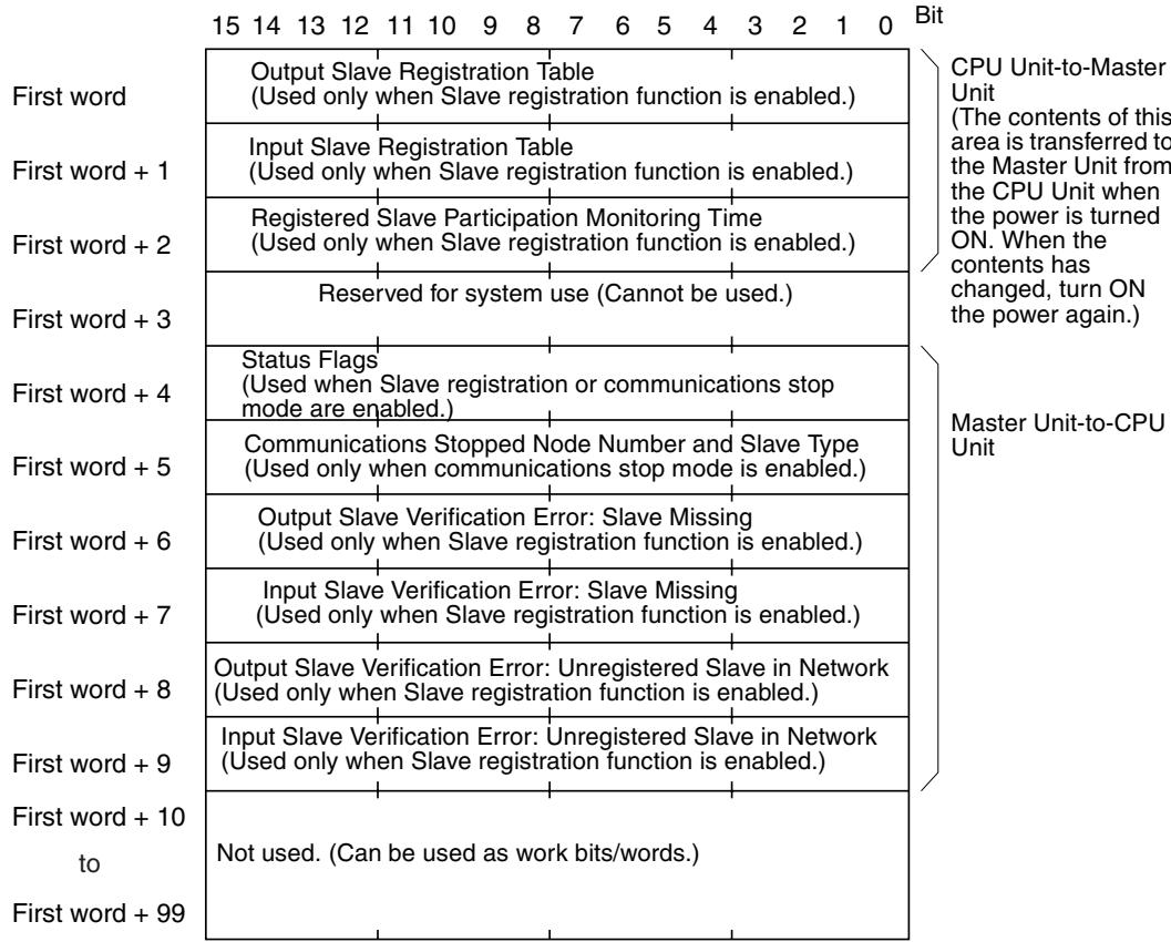
The contents from the first word to the first word +9 cannot be used for any other purpose. They can be used, however, if the Slave registration function and communications stop mode are not enabled.
The functions of each area are given in the following table.
| Word | Bit | Name | Function | ||
| +0 | 00 | Output Slave Regis-tration Table | OUT0 | Registers a list of the Output Slaves that are normally oper-ating in the network. This list is used for checking the Slaves with the Slave registration func-tion. Bits 00 to 15 correspond to Slave node numbers 0 to 15. The Output Slave is registered by turning ON its correspond-ing bit. | The bits in the Special I/O Unit Area must be registered to cor-respond to the node numbers actually used by the Slaves. Therefore, for Slaves with 16 points or higher, turn ON the bits for the other node numbers too. For example, the two consecutive bits used by a 16-point Slave or the four consecutive bits used by a 32-point Slave must be set. |
| 01 | OUT1 | ||||
| 02 | OUT2 | ||||
| to | to | ||||
| 13 | OUT13 | ||||
| 14 | OUT14 | ||||
| 15 | OUT15 | ||||
| +1 | 00 | Input Slave Registra-tion table | IN0 | Registers a list of the Input Slaves that are normally oper-ating in the network. This list is used to check the Slaves with the Slave registration function. Bits 00 to 15 correspond to Slave node numbers 0 to 15. The Input Slave is registered by turning ON its corresponding bit. | |
| 01 | IN1 | ||||
| 02 | IN2 | ||||
| to | to | ||||
| 13 | IN13 | ||||
| 14 | IN14 | ||||
| 15 | IN15 | ||||
| +2 | 00 to 15 | Registered Slave Par-ticipation Monitoring Time | The waiting time between when the Master Unit is started until the Slaves start to be checked using the Slave registration function. The time is set in increments of 1 ms as a hexadecimal. The setting range is 0000 (default is 2000 ms) or 0001 to FFDC (1 to 65500 ms). If the monitoring time lapses and there are still registered Slaves not joined in the network, a verification error (Slave missing) will occur. | ||
| +3 | 00 to 15 | Reserved for system use. | |||
| Word | Bit | Name | Function | ||
| +4 | 00 | Registration Com-pleted Flag | This flag is turned ON when all registered Slaves have joined the network. If all the registered Slaves have joined the network within the registered Slave participation monitoring time this flag will turn ON even if unregistered Slaves have also joined. The flag will not turn ON, however, if there are no Slaves set in the Slave registration table. The flag will remain ON until the power is turned OFF and ON again or the Unit is restarted. | ||
| 00 to 07 | Reserved for system use. | ||||
| 08 | Verification Error Flag: Slave Missing | This flag is turned ON under the following conditions. Registered Slaves do not join the network within the registered Slave participation monitoring time. When the Slave that caused the verification error is joined in the network, the flag will automatically be turned OFF. Check which Slave caused the error in the bit for verification error (Slave missing) in Output Slave (first word + 6) or verification error (Slave missing) in Input Slave (first word + 7). | |||
| 09 | Verification Error Flag: Unregistered Slave in Network | This flag is turned ON when an unregistered Slave has joined the network. The flag will remain ON until the power is turned OFF and ON again or the Unit is restarted, even if the Slave that caused the verification error is removed from the network. Check which Slave caused the error in the bit for Output Slave verification error (unregistered Slave in network) (first word + 8) or Input Slave verification error (unregistered Slave in network) (first word + 9). | |||
| 10 | Communications Stopped Flag | This flag is turned ON when the Master Unit is set to communications stop mode and remote I/O communications stop due to a communications error., Once the flag has turned ON, the status remains until the power is turned OFF and ON again or the Unit is restarted. Check which Slave caused the error in the bits for communications stopped node number (bits 00 to 07 of first word + 5) and communications stopped Slave type (bit 15 of first word + 5). | |||
| 11 to 14 | Reserved for system use. | ||||
| 15 | Error Flag | This flag is turned ON when any of the bits 08 to 10 are set to1(ON). The flag is automatically turned OFF when all the bits 08 to 10 are turned OFF. | |||
| +5 | 00 to 07 | Communications Stopped Node Number | When the Master Unit is set to communications stop mode and remote I/O communications stop due to a communications error, the node number of the Slave that caused the error is stored as a 2-digit hexadecimal (00 to 0F: 1 to 15). Check the Slave type (Output or Input) in the word for communications stopped Slave type (bit 15 of first word + 5). The node address stored will be held until the power is turned OFF and ON again or the Unit is restarted. | ||
| 08 to 14 | Reserved for system use. | ||||
| 15 | Communications Stopped Slave type | When the Master Unit is set to communications stop mode and remote I/O communications stop due to a communications error, the Slave type of the Slave that caused the error is stored as follows: 0 (OFF): Output Slave 1 (ON): Input Slave Check which Slave caused the error in the bits for communications stopped node number (bits 00 to 07 of first word + 5) When communications have stopped, the bit status is held until the power is turned OFF and ON again or the Unit is restarted. | |||
| Word | Bit | Name | Function | ||
| +6 | 00 | Output Slave Verifica-tion Error: Slave Miss-ing | OUT0 | When the Slave registration function is enabled, the bit corresponding to the node number of the Output Slave that caused the verification error (Slave missing) will be turned ON. Bits 00 to 15 correspond to Output Slave node numbers 1 to 15. When the Slave that caused the verification error joins the network, the bit will automatically turned OFF. | The bits in the Special I/O Unit Area correspond to the node numbers actually used by the Slaves. Therefore, for Slaves with 16 points or higher, the bits other than those set for the node number may also be turned ON. For example, the two consecutive bits used by a 16-point Slave or the four consecutive bits used by a 32-point Slave may be turned ON at the same time. |
| 01 | OUT1 | ||||
| 02 | OUT2 | ||||
| to | to | ||||
| 13 | OUT13 | ||||
| 14 | OUT14 | ||||
| 15 | OUT15 | ||||
| +7 | 00 | Input Slave Verifica-tion Error: Slave Miss-ing | IN0 | When the Slave registration function is enabled, the bit corresponding to the node number of the Input Slave that caused the verification error (Slave missing) will be turned ON. Bits 00 to 15 correspond to Input Slave node numbers 1 to 15. When the Slave that caused the verification error joins the network, the bit will automatically turned OFF. | |
| 01 | IN1 | ||||
| 02 | IN2 | ||||
| to | to | ||||
| 13 | IN13 | ||||
| 14 | IN14 | ||||
| 15 | IN15 | ||||
| +8 | 00 | Output Slave Verifica-tion Error: Unregis-tered Slave in Network | OUT0 | When the Slave registration function is enabled, the bit corresponding to the node number of the Output Slave where a verification error (unregistered Slave in network) will be turned ON. Bits 00 to 15 correspond to Output Slave node numbers 1 to 15. Once a bit has been turned ON the status will be held until the power is turned OFF and ON again or the Unit is restarted. | |
| 01 | OUT1 | ||||
| 02 | OUT2 | ||||
| to | to | ||||
| 13 | OUT13 | ||||
| 14 | OUT14 | ||||
| 15 | OUT15 | ||||
| +9 | 00 | Input Slave Verifica-tion Error: Unregis-tered Slave in Network | IN0 | When the Slave registration function is enabled, the bit corresponding to the node number of the Input Slave where a verification error (unregistered Slave in network) will be turned ON. Bits 00 to 15 correspond to Input Slave node numbers 1 to 15. Once a bit has been turned ON the status will be held until the power is turned OFF and ON again or the Unit is restarted. | |
| 01 | IN1 | ||||
| 02 | IN2 | ||||
| to | to | ||||
| 13 | IN13 | ||||
| 14 | IN14 | ||||
| 15 | IN15 | ||||
Slave Registration Function Procedure
When the Slave registration function is used, the Output/Input Slave registration table and registered Slave participation monitoring time must be set in the Special I/O Unit DM Area, but the power must be turned OFF and ON again or the Unit restarted to enable the settings.
The following example shows the procedure for using the Slave registration function. (Information on other Slave registration function settings and connections are omitted here.)
1,2,3... 1. Turn OFF pin 4 of the DIP switch on the Master Unit to disable the Slave registration function.
- Turn ON the power to the CPU Unit to which the Master Unit is mounted.
-
Use a Programming Device for the CPU Unit to set the following information in the Special I/O Unit DM Area words used by the Master Unit.
-
Output Slave registration table
- Input Slave registration table
-
Registration Slave participation monitoring time
-
Turn OFF the power to the CPU Unit to which the Master Unit is mounted.
- Turn ON pin 4 of the DIP switch on the Master Unit to enable the Slave registration function
- Turn ON the power to the CPU Unit to which the Master Unit is mounted or restart the Master Unit.
The settings in the Special I/O Unit DM Area can be set while pin 4 of the DIP switch on the Master Unit is set to ON, but a verification error may occur due to the incorrectly set Slave registration table.
4-3-6 Allocations for Master Unit in PLC
The following table shows the words in the CPU Unit that are related to the Master Unit.
| Data area | Bit(s) | Name | Function |
| Auxiliary Area (A) | A33000 to A33015 | Special I/O Unit Restarting Flags | These flags are turned ON while a Special I/O Unit is restarting. Each bit corresponds to the Unit with the same unit number. |
| A40113 | Dual Number Use Error Flag (Fatal Error) | This flag is turned ON in the following situations: When the same unit number has been set on more than one CS1 CPU Bus Unit. When the same unit number has been set on more than one Special I/O Unit. When the same word is allocated more than once for Basic I/O Units. | |
| A40206 | Special I/O Unit Error Flag | This flag is turned ON when the same unit number has been set on more than one Special I/O Unit, or when an error has occurred during data transfer between the PLC and the Special I/O Unit. The unit number of the Unit is written to word A418. | |
| A41100 to A41115 | Special I/O Unit Number Duplication Flags | These flags are turned ON when the same unit number has been set on more than one Special I/O Unit (i.e., when A40113 is ON). Each bit corresponds to the Unit with the same unit number. | |
| A41800 to A41815 | Special I/O Unit Error Flags | These flags are turned ON when the same unit number has been set on more than one Special I/O Unit, or when an error has occurred during data transfer between the PLC and the Special I/O Unit. Each bit corresponds to the Unit with the same unit number. | |
| A50200 to A50215 | Special I/O Unit Restart Bits | Turn the corresponding bit ON and then OFF to restart a Special I/O Unit. Each bit corresponds to the Unit with the same unit number. | |
| PLC Setup | 22600 to 22615 | Special I/O Unit Refresh Disable Bits | Turn the corresponding bit ON to disable refreshing of the corresponding Special I/O Unit (except those on Slave Racks). |
4-4 CQM1-SRM21-V1 Master Unit for CQM1 PLCs
4-4-1 Specifications and Part Names
Specifications
General Specifications
General specifications conform to those of the SYSMAC CQM1 and CQM1H PLCs.
Performance Specifications
| Item | Specifications |
| Model | CQM1-SRM21-V1 |
| Unit classification | Special I/O Unit |
| Internal current consumption | 5 V DC, 180 mA max. |
| Weight | 200 g max. |
| Max. number of Masters | CQM1 PLC: 1 Master Unit CQM1H PLC: Up to the maximum number of I/O points that can be connected to the CPU Unit. |
| Master Unit mounting location | No restrictions. |
| Max. number of I/O points per Master | CQM1-CPU11/21: 32 points (16 inputs/16 outputs) or 64 points (32 inputs/32 outputs) CQM1-CPU41/42/43/44-V1 or CQM1H: 32 points (16 inputs/16 outputs), or 64 points (32 inputs/32 outputs), or 128 points (64 inputs/64 outputs) (Switch using DIP switch setting) Uses the I/O Area in the CPU Unit. |
| Number of points per node number | 8 or 4 points |
| Number of usable node numbers per Master | 8 points per node number: INO to IN1 and OUT0 to OUT1, or INO to IN3 and OUT0 to OUT3, or INO to IN7 and OUT0 to OUT7 4 points per node number: INO to IN3 and OUT0 to OUT3, or INO to IN7 and OUT0 to OUT7, or INO to IN15 and OUT0 to OUT15 |
Alarm Output Specifications
| Item | Specification |
| Maximum switching capacity | 2 A (24 V DC) |
| Minimum switching capacity | 10 mA (5 V DC) |
| Relay type | G6D-1A |
| Minimum ON time | 100 ms (Outputs are ON at least 100 ms.) |
| Circuit configuration | CQM1-SRM21-V1 Internal circuitry 2 A, 24 V DC max. |
Caution
For conformance to the EC Directives (Low-voltage Directives), provide reinforced insulation or double insulation for the power source that is used for the alarm output.
Dimensions
The following diagram shows the dimensions of the CQM1-SRM21-V1 Master Unit. All dimensions are in mm.
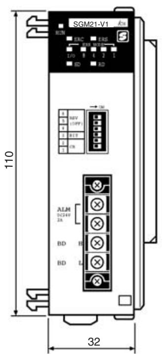
(When the cover is removed)
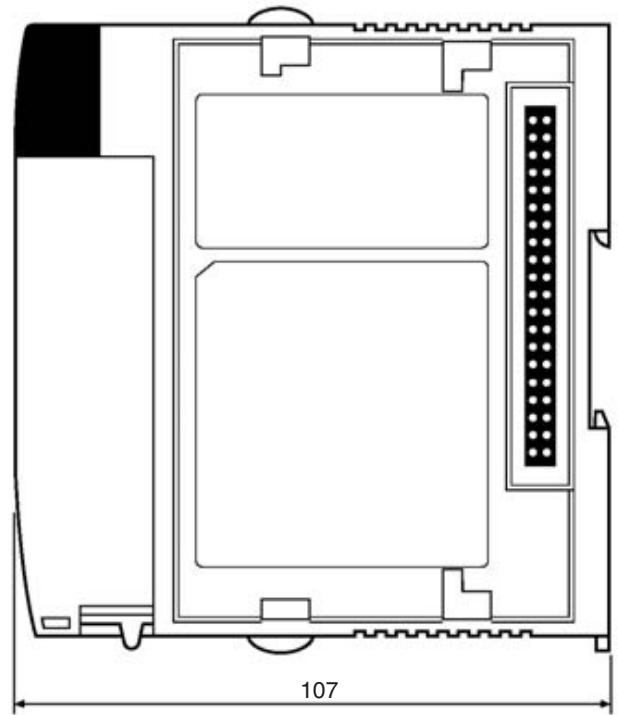
Note Refer to the CQM1 Operation Manual (W226) for details on the dimensions when the Master Unit is installed.
Master Unit Components
The following diagram shows the main components of the CQM1-SRM21-V1 Master Unit. The functions of these components are described below.
Terminal block screws
These screws attach the terminal block. The terminal block can be removed when these screws are loosened.
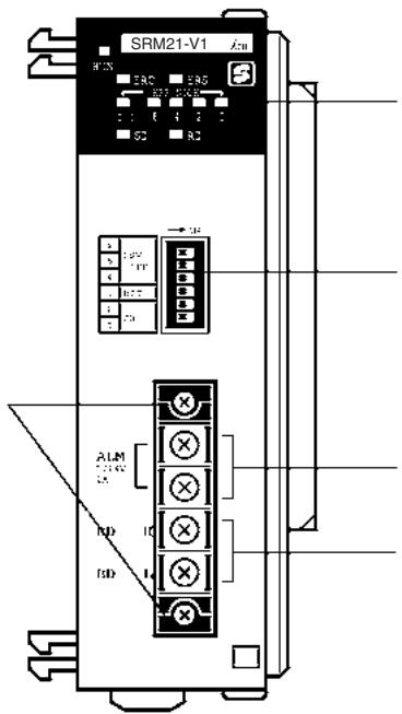
Indicators
Indicates the operating status of the Master Unit and the status of communications with the Slaves.
DIP Switch
These pins have the following functions:
Pins 1 and 2: PLC word allocation setting
Pin 3: Number of points/unit number setting
Pin 4: Communications mode
Pins 5 to 6: Reserved (Always OFF.)
Alarm Output Terminals
These terminals are shorted when an error occurs.
Connect to a warning device.
Communications Terminals
Connect the Slaves' transmission cable to these terminals.
Indicators
The following table shows the meaning of the indicators.
| Indicator | Status | Meaning |
| RUN (green) | ON | The Unit is operating normally. |
| OFF | Indicates one of the following conditions:The power is OFF, there is an I/O UNIT OVER error, or there is an I/O Bus error. | |
| SD (yellow) | ON | Data is being transmitted. |
| OFF | Data is not being transmitted. | |
| RD (yellow) | ON | Data is being received. |
| OFF | Data is not being received. | |
| ERC (red) | ON | A Slave has been withdrawn from communications.(Communications error) |
| OFF | The Slaves are communicating normally. | |
| ERS (red) | ON | The data areas between the Slaves overlaps when the number of points/unit number setting is set to 4-point mode. |
| Flashing | A node number is out-of-range, as follows:(The Unit doesn't check for node numbers 8 or higher.)The PLC is allocated 2 words and the number of points/unit number is set to 8-point mode, but the node number is 2 to 7.The PLC is allocated 4 words and the number of points/unit number is set to 8-point mode, but the node number is 4 to 7.The PLC is allocated 2 words and the number of points/unit number is set to 4-point mode, but the node number is 4 to 7. | |
| OFF | The data area and address settings are correct. | |
| IN/OUT (red) | ON | An error has occurred with an Output Slave. |
| OFF | An error has occurred with an Input Slave or all Slaves are operating normally. | |
| 8421 (red) | ON/OFF | These indicators represent the four-digit binary slave number of the Slave in which the error occurred. |
4-4-2 Switch Settings
DIP Switch
The DIP switch is used to make the PLC word allocation setting and the number of points/unit number setting.
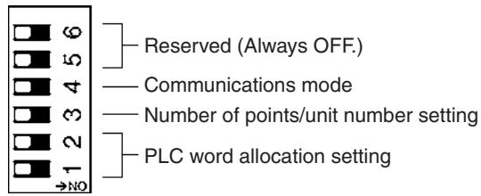
Set the PLC word allocations with pins 1 and 2, as shown in the following table. This is the total number of words allocated to Slaves in the PLC.
| Pin 1 | Pin 2 | Max. number of Slaves setting |
| OFF | OFF | 2 words (1 input word, 1 output word) |
| ON | OFF | 4 words (2 input words, 2 output words) |
| OFF | ON | 8 words (4 input words, 4 output words) |
| ON | ON |
- The Master Unit is shipped with pins 1 and 2 set to OFF (2 words).
- Word addresses are allocated separately for inputs and outputs. The words are allocated in order from the left of the PLC to the right, just like regular I/O Units.
Note Always turn OFF the PLC's Power Supply before changing the setting.

Caution Always set pin numbers 5 to 6 of the DIP switch to OFF.
Set the number of points/unit number with pin 3, as shown in the following table.
| Pin 3 | Number of I/O points/Unit number |
| OFF | 8 points (8-point mode) |
| ON | 4 points (4-point mode) |
The following table shows all of the possible combinations of DIP switch settings.
| Setting | PLC word allocation | Max. number of I/O points | Points/n ode number | Usable node numbers | Communications cycle time | Use of Ana-log Termi-nals | |||
| Pin 1 | Pin 2 | Pin 3 | High-speed Communi-cations Mode | Long-dis-tance Communi-cations Mode | |||||
| OFF | OFF | OFF | 2 words (1 IN/1 OUT) | 16 input points, 16 output points | 8 points | IN: 0 and 1 OUT: 0 and 1 | 0.5 ms | 4.0 ms | Possible (Only for Master Unit models with-V1. Not pos-sible for models with-out V1.) |
| ON | OFF | OFF | 4 words (2 IN/2 OUT) | 32 input points, 32 output points | 8 points | IN: 0 to 3 OUT: 0 to 3 | 0.5 ms | 4.0 ms | |
| OFF | ON | OFF | 8 words (4 IN/4 OUT) | 64 input points, 64 output points | 8 points | IN: 0 to 7 OUT: 0 to 7 | 0.5 ms | 4.0 ms | |
| ON | ON | OFF | |||||||
| OFF | OFF | ON | 2 words (1 IN/1 OUT) | 16 input points, 16 output points | 4 points | IN: 0 to 3 OUT: 0 to 3 | 0.5 ms | 4.0 ms | Not possible |
| ON | OFF | ON | 4 words (2 IN/2 OUT) | 32 input points, 32 output points | 4 points | IN: 0 to 7 OUT: 0 to 7 | 0.5 ms | 4.0 ms | |
| OFF | ON | ON | 8 words (4 IN/4 OUT) | 64 input points, 64 output points | 4 points | IN: 0 to 15 OUT: 0 to 15 | 0.8 ms | 6.0 ms | |
| ON | ON | ON | |||||||
Note When the CQM1 Master Unit is used in 4-point mode, Slaves with 16 points or more cannot be used. If Slaves with 16 points or more are used, a data area overlap error (ERS indicator lit) will occur.
Set the communications mode with DIP switch pin 4 (DR), as shown in the following table.
| Pin 4 | Communications mode setting | Communications distance | Communications baud rate | Communications cycle time |
| OFF | High-speed Communications Mode | 100 m max. | 750 kbps | 0.5 or 0.8 ms |
| ON | Long-distance Communications Mode | 500 m max. | 93.75 kbps | 4.0 or 6.0 ms |
Note
- Make sure that the communications mode of the Master Unit is the same as that of all the Slaves. If the CompoBus/S System contains a Slave with a different communications mode, the COMM indicator on that Slave will not light, and normal communications with that Slave will not be possible. Other Slaves will not be adversely affected, and the COMM indicator on the Master Unit will light normally. For information relating to the states of the Master Unit indicator, refer to 6-5-1 Indicators.
- When using a previous Master Unit model (without V1), pin 4 must be set to OFF. Otherwise, normal communications may not be possible.
- Pin 4 is factory-set to OFF (High-speed Communications Mode).
- The settings for the communications distance, baud rate, and communications cycle time vary according to the setting of pin 4, as shown in the above table.
4-4-3 I/O Allocations in CQM1 PLCs
In CQM1 PLCs, the Master Unit is treated just like an I/O Unit that has both inputs and outputs, so the Slave's I/O data is stored in the words allocated to those inputs and outputs.
Master Unit Settings
The group of words allocated to the Master is determined by the mounting position of the Master Unit, and the specific bits used by each Slave are determined by the node number set on the Slave.
- Master Units for CQM1 PLCs don't have the status area information that is provided with the Master Units for CS-series, C200HX/C200HG/C200HE-(Z)E, and C200HS PLCs.
- The following equation shows the maximum time required for inputs from the Input Slaves and outputs to the Output Slaves to become effective after the CompoBus/S System is turned ON.
In High-speed Communications Mode: (PLC cycle time) + 118 ms
In Long-distance Communications Mode: (PLC cycle time) + 720 ms.
This delay must be taken into account when writing ladder programs for the PLC. It is recommended to write a routine in the ladder program that checks whether the alarm output terminal is OFF before processing I/O with the Slaves.
The following settings affect I/O allocations to Slaves of the Master Units used with CQM1 PLCs.
PLC Word Allocation
In order for the Master Unit to allocate words to Slaves, the total number of words allocated to the Master Unit must be set in the PLC. The following three settings can be made:
2 words (1 input word, 1 output word)
4 words (2 input words, 2 output words)
8 words (4 input words, 4 output words)
Number of Points/Node Number
This setting determines the amount of memory (number of bits) allocated to each node number. The following two settings can be made:
8 points (8-point mode)
4 points (4-point mode)
Refer to the table on page 129 for details on the possible combinations of DIP switch settings.
Slave Allocations
The Slaves are allocated input and output words as shown below. In CompoBus/S Systems, the node numbers of Input Slaves and Output Slaves are handled separately so the same node numbers can be set for both one Input and one Output Slave.
I/O Allocations in 8-point Mode
PLC Word Allocation: 2 Words
The following diagram shows the I/O allocations when the DIP switch is set as shown below.
Pin 1: OFF
Pin 2: OFF
Pin 3: OFF

PLC Word Allocation: 4 Words
The following diagram shows the I/O allocations when the DIP switch is set as shown below.
Pin 1: ON
Pin 2: OFF
Pin 3: OFF
Inputs: First word
Inputs: First word + 1
| Input Slave 1 | Input Slave 0 |
| Input Slave 3 | Input Slave 2 |
Outputs: First word
Outputs: First word + 1
| Output Slave 1 | Output Slave 0 |
| Output Slave 3 | Output Slave 2 |
PLC Word Allocation: 8 Words
The following diagram shows the I/O allocations when the DIP switch is set as shown below.
Pin 1: OFF
Pin 2: ON
Pin 3: OFF
or
Pin 1: ON
Pin 2: ON
Pin 3: OFF
Inputs: First word
Inputs: First word + 1
Inputs: First word + 2
Inputs: First word + 3
| Input Slave 1 | Input Slave 0 |
| Input Slave 3 | Input Slave 2 |
| Input Slave 5 | Input Slave 4 |
| Input Slave 7 | Input Slave 6 |
Outputs: First word
Outputs: First word + 1
Outputs: First word + 2
Outputs: First word + 3
| Output Slave 1 | Output Slave 0 |
| Output Slave 3 | Output Slave 2 |
| Output Slave 5 | Output Slave 4 |
| Output Slave 7 | Output Slave 6 |
Note When the number of points/node number is set to 8-point mode, each 16-point Slave (input or output) is treated as 2 node numbers and those bits are allocated so that all 16 bits are in the same word, as described below.
When an odd node number has been set, the previous node number's allocated memory is also used.
When an even node number has been set, the next node number's allocated memory is also used.
For example, when a 16-output Slave's node number is set to 3, the Slave uses the bits for Output Slave 2 and Output Slave 3. When the node number is set to 0, the Slave uses the bits for Output Slave 0 and Output Slave 1.
The Slave with 4 inputs or 4 outputs is regarded as one Slave Unit.
When an odd node number has been set:
Bits 8 to 11 are used and bits 12 to 15 are not used.
When an even node number has been set:
Bits 0 to 3 are used and bits 4 to 7 are not used.
An Analog Terminal uses 64, 48, 32, or 16 points. For this reason, in 8-point mode, I/O allocations are as shown in the following table.
| Number of points allocated | Node number setting | Node numbers used | Valid setting range | ||
| 2 words allocated | 4 words allocated | 8 words allocated | |||
| 64 pointsSRT2-AD04: 4 inputs | Odd number | Node number setting - 1 to node number setting + 6 | Not possible | Not possible | 0 to 1 |
| Even number | Node number setting to node number setting + 7 | ||||
| 48 pointsSRT2-AD04: 3 inputs | Odd number | Node number setting - 1 to node number setting + 4 | Not possible | Not possible | 0 to 3 |
| Even number | Node number setting to node number setting + 5 | ||||
| 32 pointsSRT2-AD04: 2 inputsSRT2-DA02: 2 outputs | Odd number | Node number setting - 1 to node number setting + 2 | Not possible | 0 to 1 | 0 to 5 |
| Even number | Node number setting to node number setting + 3 | ||||
| 16 pointsSRT2-AD04: 1-inputSRT2-DA02: 1-output | Odd number | Node number setting - 1 to node number setting | 0 to 1 | 0 to 3 | 0 to 7 |
| Even number | Node number setting to node number setting + 1 | ||||
If a node number is outside the setting range, the words allocated to the Slave will extend beyond the input or output area, which will prevent the Slave participating in communications. If this happens, the COMM indicator will not light.
Connector Terminals with 32 inputs or 32 outputs are allocated the words for four 8-point nodes, i.e., they are allocated two I/O words. Therefore, the following nodes will be used in addition to the set nodes. Connector Terminals with 16 inputs or 16 outputs will be allocated I/O as Slaves with 16 inputs or Slaves with 16 outputs for the node number setting.
| Node number setting | Node numbers used | Valid setting range | ||
| 2 words allocated | 4 words allocated | 8 words allocated | ||
| Odd number | Node number setting - 1 to node number setting + 2 | Not possible | 0 to 1 | 0 to 5 |
| Even number | Node number setting to node number setting + 3 | |||
If a node number is not within the setting range, the words allocated to the Slave will extend beyond the input or output area, which will prevent the Slave from participating in communications. If this happens, the COMM indicator will not light.
I/O Allocation Example (4 Words)
In this example the number of points/node number is set to 8, the PLC word allocations are set to 4 words, and the system has the configuration shown in the following diagram. (The node numbers are indicated by #0, #1, and #2.)
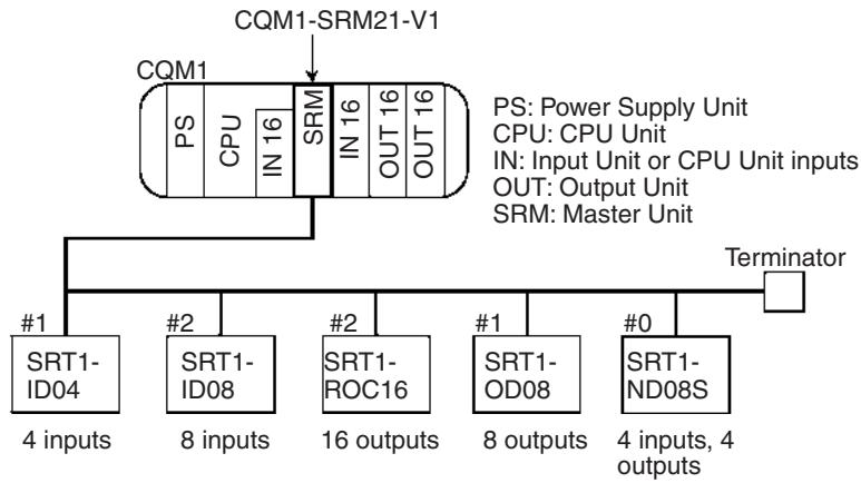
The I/O allocations for this system are shown below.
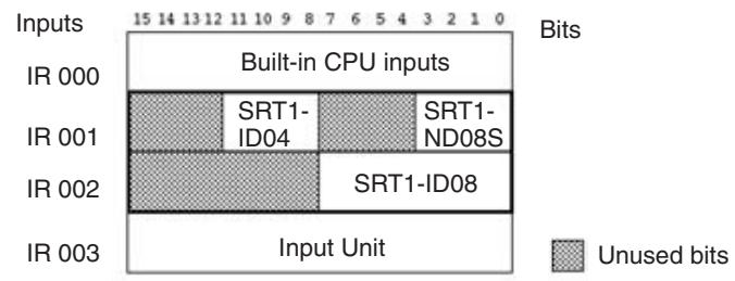
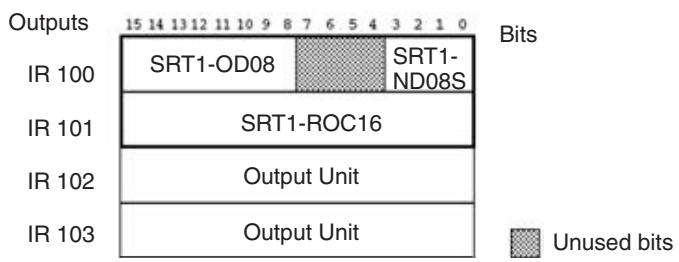
I/O Allocations in 4-point Mode
PLC Word Allocation: 2 Words
The following diagram shows the I/O allocations when the DIP switch is set as shown below.
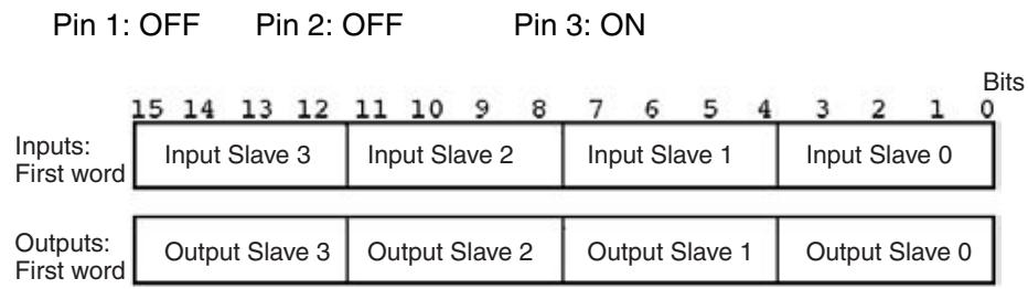
PLC Word Allocation: 4 Words
The following diagram shows the I/O allocations when the DIP switch is set as shown below.
Pin 1: ON
Pin 2: OFF
Pin 3: ON
| Inputs: First word | Input Slave 3 | Input Slave 2 | Input Slave 1 | Input Slave 0 |
| Inputs: First word + 1 | Input Slave 7 | Input Slave 6 | Input Slave 5 | Input Slave 4 |
| Outputs: First word | Output Slave 3 | Output Slave 2 | Output Slave 1 | Output Slave 0 |
| Outputs: First word + 1 | Output Slave 7 | Output Slave 6 | Output Slave 5 | Output Slave 4 |
PLC Word Allocation: 8 Words
The following diagram shows the I/O allocations when the DIP switch is set as shown below.
Pin 1: OFF
or
Pin 1: ON
Pin 2: ON
Pin 3: ON
Pin 3: ON
Inputs: First word
Inputs: First word + 1
Inputs: First word + 2
Inputs: First word + 3
Outputs: First word
Outputs: First word + 1
Outputs: First word + 2
Outputs: First word + 3
| Input Slave 3 | Input Slave 2 | Input Slave 1 | Input Slave 0 |
| Input Slave 7 | Input Slave 6 | Input Slave 5 | Input Slave 4 |
| Input Slave 11 | Input Slave 10 | Input Slave 9 | Input Slave 8 |
| Input Slave 15 | Input Slave 14 | Input Slave 13 | Input Slave 12 |
| Output Slave 3 | Output Slave 2 | Output Slave 1 | Output Slave 0 |
| Output Slave 7 | Output Slave 6 | Output Slave 5 | Output Slave 4 |
| Output Slave 11 | Output Slave 10 | Output Slave 9 | Output Slave 8 |
| Output Slave 15 | Output Slave 14 | Output Slave 13 | Output Slave 12 |
In 4-point mode, 8-point Slaves use two node numbers.
| Slave | Node number setting | Node number actually used |
| 8-point Slave | Odd number | Node number setting to node number setting + 1 |
| Even number |
Example:
When the PLC word allocations are set to 8 words and an 8-output Slave's node number is set to 3, the Slave uses the words for Input Slave 3 and Input Slave 4.
I/O Allocation Example (2 Words)
In this example the number of points/node number is set to 4, the PLC word allocations are set to 2 words, and the system has the configuration shown in the following diagram. (The node numbers are indicated by #0, #1, #2, and #3.)
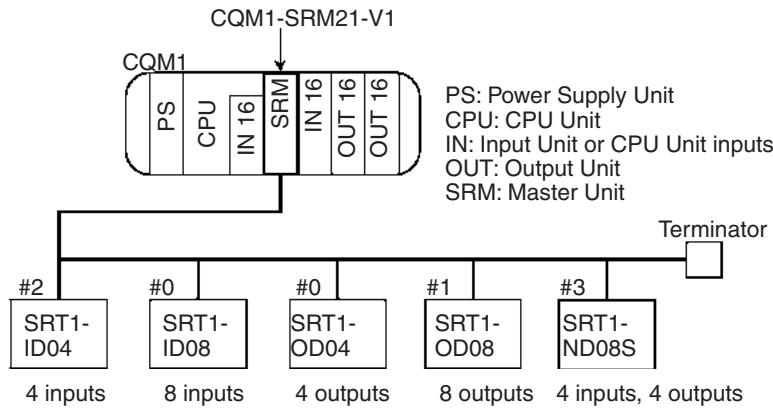
The I/O allocations for this system are shown below.
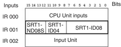
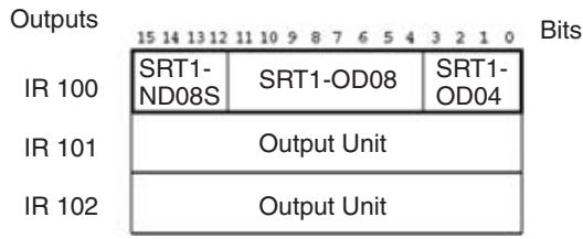
4-5 SRM1-C0□-V2 Master Control Units
The SRM1 Master Control Unit contains both CPU Unit and Master Unit and it connects to all I/O using CompoBus/S. This manual provides SRM1 specifications only. For details, refer to the CompoBus/S SRM1(-V2) Master Control Unit Operation Manual (W318).
4-5-1 Specifications and Part Names
Specifications
| Item | Specifications | |
| Model | SRM1-C01-V2 | SRM1-C02-V2 |
| Port | Peripheral port | Peripheral port RS-232C port |
General Specifications
| Item | Specifications |
| Power supply voltage | 24 V DC |
| Allowable power supply voltage | 20.4 to 26.4 V DC |
| Power consumption | 3.5 W max. |
| Inrush current | 12.0 A max. |
| Noise immunity | 1500 Vp-p with a pulse width of 0.1 to 1 μs and a rise time of 1 ns (via impulse noise simulator) |
| Vibration resistance | Conforming to JIS C0911: 10 to 57 Hz with single-amplitude of 0.075 mm 57 to 150 Hz with fixed acceleration of 9.8 m/s² 10 sweeps each in X, Y, and Z directions (8 minutes per sweep × 10 sweeps = 80 minutes) |
| Shock resistance | Conforms to JIS C0912 147 m/s² 3 times each in X, Y, and Z directions |
| Ambient temperature | Operating: 0 to 55°C Storage: -20 to 75°C |
| Ambient operating relative humidity | 10% to 90% (with no condensation) |
| Operating environment | No corrosive gases |
| Terminal screw size | M3 |
| Power holding time | DC power: 2 ms min. |
| Weight | 150 g max. |
Master Specifications
| Item | Specifications |
| I/O points | 256 points (128 inputs/128 outputs) or 128 points (64 inputs/64 outputs) (Determined by the usable node number setting in DM. The default setting is 256 points.) |
| Number of points per node number | 8-point mode |
| Usable node numbers | IN0 to IN15/OUT0 to OUT15 or IN0 to IN7/OUT0 to OUT7 (Can be switched with setting in DM.) |
| I/O words | Input: IR 000 to 007 Output: IR 010 to 017 |
| Programming language | Ladder program |
| Instructions | 14 basic instruction + 81 special instructions with 129 variations |
| Processing speed | LD instruction: 0.97 μs, MOV instruction: 9.1 μs |
| Program capacity | 4,096 words |
| Data memory | 2,022 words + 512 words (Read only) |
| Timers/Counters | 128 total |
| Work bits | 640 |
| Memory backup | Flash memory: User programs, etc. (without battery) Lithium battery: Data memories, etc. (Battery life: 10 years or more at ambient temperature of 25°C) |
| Peripheral port | 1 port |
| RS-232C port | 1 port (SRM1-C02-V2 only) Host link, NT link, 1:1 PLC link, ASCII data transfer with XON, XOFF flow control |
| Programming Devices | Programming Console (CQM1-PR001-E/C200H-PR027-E) SYSMAC Support Software C500-ZL3AT1-E (for IBM PC/AT, English version) |
Dimensions (Common)
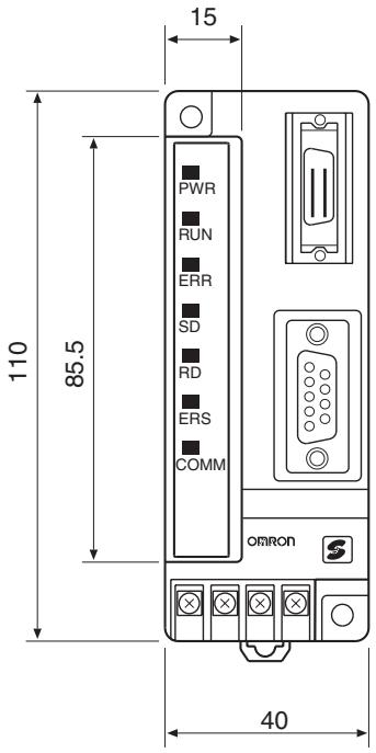
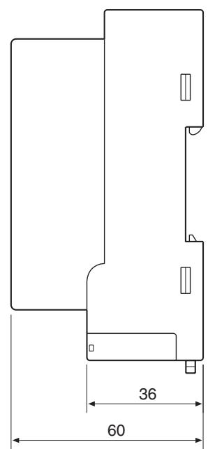
Mounting Holes
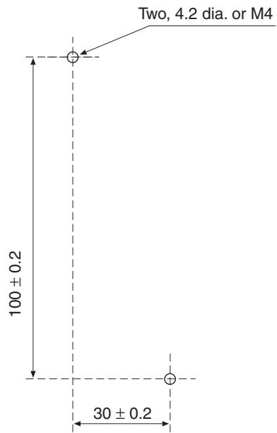
(Unit: mm)
Name and Function of Parts
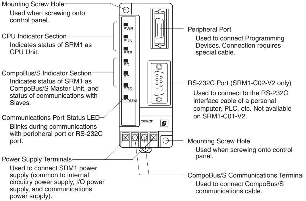
Indicators
The following table shows the meaning of the indicators.
| Indicator | Status | Meaning |
| PWR (green) | ON | Power ON |
| OFF | Power OFF | |
| RUN (green) | ON | RUN/MONITOR mode |
| OFF | PROGRAM mode or abnormal stop | |
| ERR (red) | ON | Fatal error (operation discontinues) |
| Flashing | Non-fatal error (operation continues) | |
| OFF | Normal | |
| SD (yellow) | ON | CompoBus/S sending data |
| OFF | CompoBus/S not sending data | |
| RD (yellow) | ON | CompoBus/S receiving data |
| OFF | CompoBus/S not receiving data | |
| ERC (red) | ON | CompoBus/S communications error |
| OFF | Other | |
| COMM (yellow) | Flashing | Communicating with peripheral port or RS-232C port |
| OFF | Other |
4-5-2 Settings
Usable Node Number Settings
The CompoBus/S System settings are described in this section.
Usable node numbers are set from a Programming Device by specifying either of the following values as BCD in data memory (bits 0 to 3 of DM6603).

Note The setting is read when SRM1 is started. After changing the setting, be sure to restart SRM1.
Communications Mode Setting
The communications mode is set from a Programming Device by specifying either of the following values as a BCD in data memory (bits 4 to 7 of DM6603).
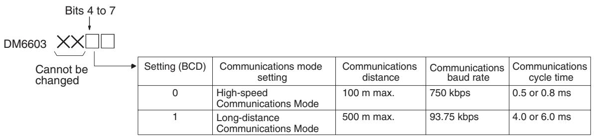
Note Long-distance Communications Mode can only be set in the SRM1-C0□-V2. Earlier models (SRM1-C0□, SRM1-C0□-V1) cannot use this mode.
4-6 CPM2C-S Series CPM2C-S□□□C (-DRT)
The CPM2C-S Series is a small PLC based on the CPM2C Series with built-in CompoBus/S Master functions. The CPM2C-S Series, like the CPM2C Series, incorporates a variety of functions, such as pulse synchronous control, input interrupt control, high-speed counters, pulse outputs, and clock functions.
Up to 32 CompoBus/S Slaves can be connected to the CPM2C-S Series to construct an I/O link system with up to 256 points (128 inputs and 128 outputs). With CompoBus/S Slaves, such as CompoBus/S Remote Terminals, Analog Terminals, Sensor Terminals, and Bit Chain Terminals connected, the CPM2C-S Series saves wiring effort and supports long-distance communications.
A model number with the suffix "-DRT" means that the model also supports DeviceNet Slave functions, thus enabling I/O linking with the DeviceNet Master.
4-6-1 Specifications and Part Names
System Configuration
The following diagram shows a system configuration of a CPM2C-S PLC with DeviceNet Slave functions.
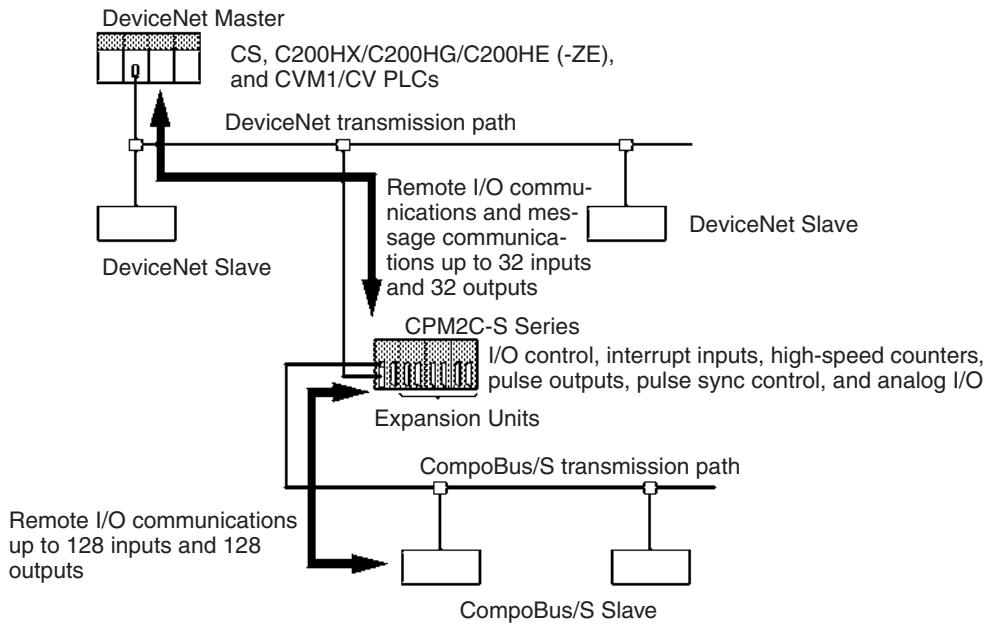
Unit Specifications
| Unit | Number of inputs | Number of outputs | Model |
| With CompoBus/S Master functions | 6 at 24 V DC | 4 NPN transistors | CPM2C-S100C |
| 4 PNP transistors | CPM2C-S110C | ||
| With CompoBus/S Master and DeviceNet Slave functions | 4 NPN transistors | CPM2C-S100C-DRT | |
| 4 PNP transistors | CPM2C-S110C-DRT |
Master Specifications
| Item | Specification | |
| Programming method | Instruction length | |
| 1 address/instruction | 1 to 5 words/instruction | |
| Number of instructions | Basic instructions: 14Special instruction: 105 (185 variations) | |
| Execution time | Basic instructions: 0.64 s (LD instruction)Special instructions: 7.8 s (MOV instruction) | |
| Program capacity | 4,096 words | |
| Maximum I/O points | CPU: 10 points (6 inputs and 4 outputs)Expansion: 338 points (182 inputs and 156 outputs) | |
| Input bits | 160 bits: 00000 to 00915 | Bits not used as I/O bits in words can be used as work bits |
| Output bits | 160 bits: 01000 to 01915 | |
| CompoBus/S input bits | 128 bits: 02000 to 02715 | Bits not used as CompoBus/S I/O bits in words can be used as work bits |
| CompoBus/S output bits | 128 bits: 03000 to 03715 | |
| Work bits | 672 bits: 02800 to 02915 (words 028 to 029), 03800 to 04915 (words 038 to 049), and 20000 to 22715 (words 200 to 227) | |
| SR bits | 448 bits: 22800 to 25515 (words 228 to 255) | |
| TR bits | 8 bits: TR0 to TR7 | |
| HR bits | 320 bits: HR 0000 to 1915 (words HR 00 to 19) | |
| AR bits | 384 bits: AR 0000 to 2315 (words AR 00 to 23) | |
| LR bits | 256 bits: LR 0000 to 1515 (words LR 00 to 15) | |
| Timer/Counters | 256 bits: TIM/CNT 000 to 2551-ms timer (TMHH instruction), 10-ms timer (TIMH instruction), 100-ms timer (TIM instruction), 1-s/10-s timer (TIML instruction), Decrementing counter (CNT instruction), and reversible counter (CNTR instruction) | |
| DM words | Read/Write: 2,048 words (DM 0000 to 2047) (DM 2000 to 2021 are the error log area.)Read-only: 456 words (DM 6144 to 6599)PLC Setup: 56 words (DM 6600 to 6655) | |
| CompoBus/S Master function | I/O points | 256 points (128 inputs and 128 outputs) or 128 points (64 inputs and 64 outputs)(Determined by the node number settings in the DM Area. The value is by default set to 256.) |
| Number of points per node number | 8-point mode | |
| Node number setting | IN0 to IN15 and OUT0 to OUT15 or IN0 to IN7 and OUT0 to OUT7 (selected with DM settings) | |
| I/O words | Input: 020 to 027 (CompoBus/S input bits)Output: 030 to 037 (CompoBus/S output bits) | |
| DeviceNet Slave function | DeviceNet remote I/O link points: Up to 1,024 points (Up to 32 input words and 32 output words)Explicit message communicationsRead/Write any desired area from the Master | |
| Power failure backup function | Flash memory: User program, DM (Read only), and PLC SetupMemory backup: Holds DM (Read/Write), HR, AR, and CNT contents with battery for 2 years at an ambient temperature of 25°C. | |
| Programming Device | CQM1H-PRO01-E, CQM1-PRO01-E, or C200H-PRO27-E Programming ConsoleWS02-CXPC1-EV2 CX-ProgrammerWS01-CPTB1-E SYSMAC-CPTC500-ZL3AT1-E SYSMAC Support Software | |
Dimensions (Same for All Units)
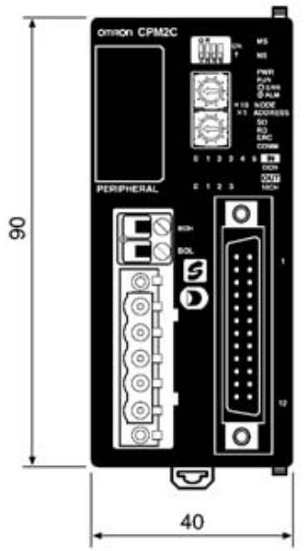
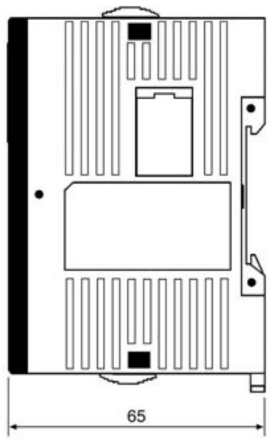
(Unit: mm)
The CPM2C-S has rotary switches for DeviceNet settings and communications connector only if the CPM2C-S model number has a suffix of "DRT." For the dimensions of the CPM2C-S with wires connected or Expansion Units mounted, refer to the CPM2C-S Series Operation Manual.
Name and Function of Parts
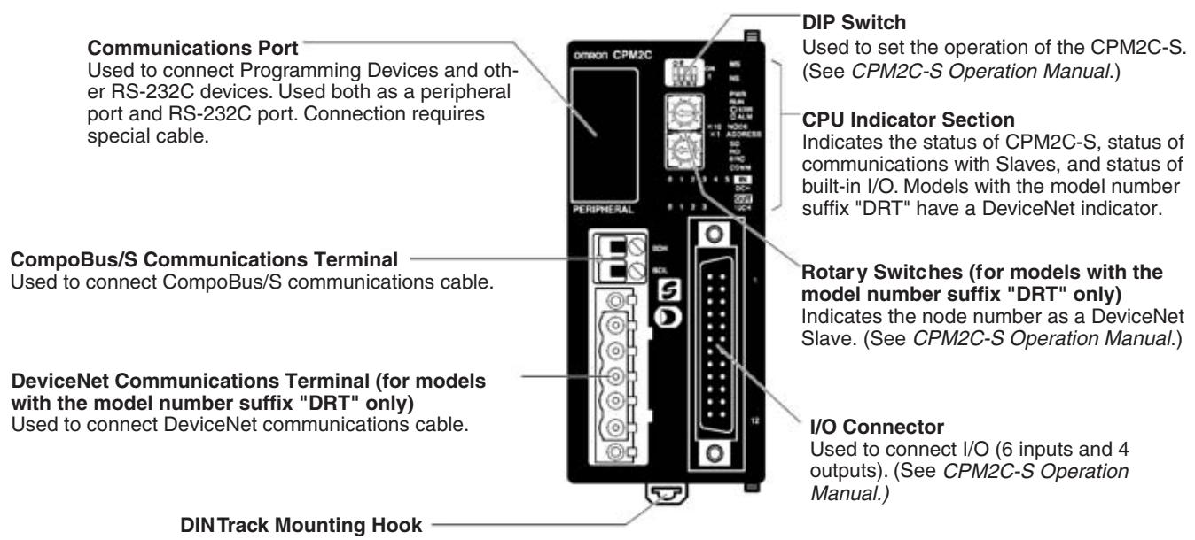
Indicators
The following table shows the meaning of the indicators.
| Indicator | Name | Color | Status | Meaning |
| PWR | Power | Green | ON | Power ON |
| OFF | Power OFF | |||
| RUN | Run | Green | ON | RUN/MONITOR mode |
| OFF | PROGRAM mode or abnormal stop | |||
| ERR/ALM | Operating error | Red | ON | Fatal error (operation stops) |
| Flashing | Non-fatal error (operation continues) | |||
| OFF | Normal | |||
| SD | Sending data | Yellow | ON | CompoBus/S sending data |
| OFF | CompoBus/S not sending data | |||
| RD | Receiving data | Yellow | ON | CompoBus/S receiving data |
| OFF | CompoBus/S not receiving data | |||
| ERC | Communications error | Red | ON | CompoBus/S communications error |
| OFF | Other | |||
| COMM | Port communications | Yellow | Flashing | Communicating with peripheral port or RS-232C port |
| OFF | Other | |||
| MS (models with model number suffix “DRT” only) | Module status | Green/Red | --- | Lights or flashes according to the status of the DeviceNet node. (See note.) |
| NS (models with model number suffix “DRT” only) | Network status | Green/Red | --- | ON, flashes, or OFF according to the status of DeviceNet network. (See note.) |
| 0 to 5 | Input | Yellow | ON | Input terminals turned ON (See note.) |
| OFF | Input terminals turned OFF (See note.) | |||
| 0 to 3 | Output | Yellow | ON | Output terminals turned ON (See note.) |
| OFF | Output terminals turned OFF (See note.) |
Note Refer to the CPM2C-S Series Operation Manual for details.
4-6-2 Settings
The CompoBus/S System settings are described in this section.
Usable Node Number Settings
Usable node numbers are set by specifying either of the following BCD values in data memory (bits 0 to 3 of DM6603).

Note The setting is read when the CPM2C-S is started. After changing the setting, be sure to restart the CPM2C-S.
Communications Mode Setting
The communications mode is set by specifying either of the following BCD values in data memory (bits 4 to 7 of DM6603).
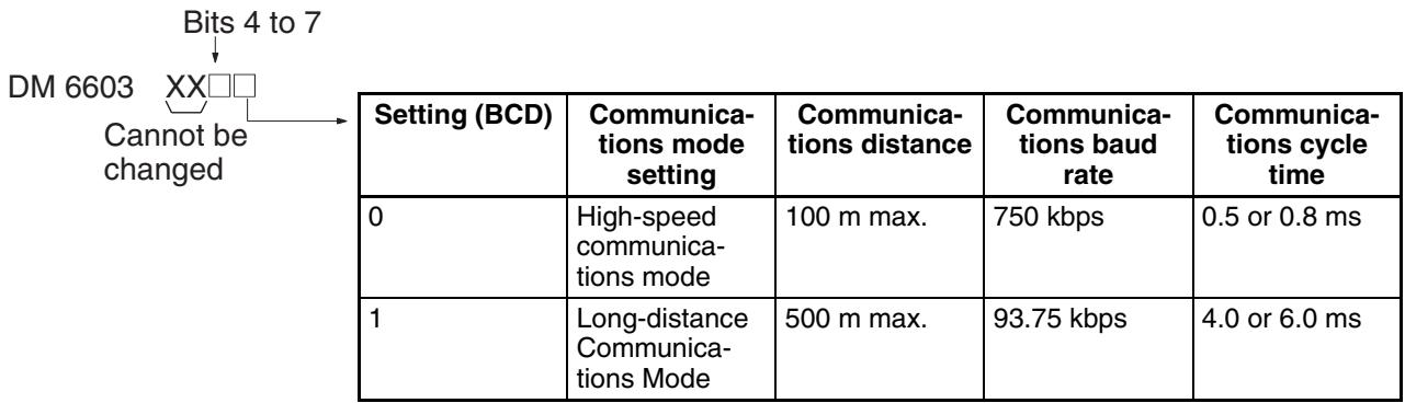
SECTION 5
Slave Specifications and Operations
This section explains the functions of each Slave, including information on specifications, switch settings, and I/O.
5-1 Remote Terminals 147
5-1-1 SRT□□-ID□□(-1) Remote Terminals with 4,8,or 16 Transistor Inputs 147
5-1-2 SRT□-ID16T (-1) Remote Terminals with 16 Transistor Inputs (and 3-tier Terminal Blocks) 157
5-1-3 SRT□-OD□(-1)RemoteTerminals with4,8,or16TransistorOutputs. 163
5-1-4 SRT□-OD16T (-1) Remote Terminals with 16 Transistor Outputs (and 3-tier Terminal Blocks). 173
5-1-5 SRT□-MD16T (-1) Remote Terminals with 8 Input and 8 Output Transistors (3-tier Terminal Block) 179
5-1-6 SRT□-RO□□□ Remote Terminals with Relay/Power MOS FETs 185
5-2 Connector Terminals 194
5-2-1 SRT2-VID□□□(-1) Connector Terminals with 8 Input or 16 Output Transistors. 194
5-2-2 SRT2-VOD□□□(-1) Connector Terminals with 8 or 16 Transistor Outputs 213
5-2-3 SRT2-ID32ML (-1) Connector Terminals with 32 Transistor Inputs 225
5-2-4 SRT2-OD32ML (-1) Connector Terminals with 32 Transistor Outputs 236
5-2-5 SRT2-MD32ML (-1) Connector Terminals with 16 Transistor Inputs and 16 Transistor Outputs 246
5-2-6 Wiring and Assembly of Communications Connector and MIL Connector for Connector Terminals. 256
5-3 Remote I/O Modules. 260
5-3-1 SRT□-□D16P Remote I/O Modules 260
5-4 Water-resistant Terminals 268
5-4-1 SRT2-ID□□CL (-1) Water-resistant Terminals with 4 or 8 Transistor Inputs. 268
5-4-2 SRT2-OD□□CL (-1) Water-resistant Terminals with 4 or 8 Transistor Outputs 277
5-4-3 Shielded Connector Wiring and Assembly. 284
5-5 Sensor Terminals 287
5-5-1 SRT□-□D08S Sensor Terminals with 8 Transistor Inputs or 4 Transistor Inputs and 4 Transistor Outputs 287
5-5-2 SRT□-OD08S Sensor Terminal with 8 Transistor Outputs 295
5-6 Fiber Amplifier Communications Units 301
5-6-1 E3X-SRT21 Fiber Amplifier Communications Unit 301
5-7 Analog Input Terminals 308
5-7-1 SRT2-AD04 Analog Input Terminal 308
5-8 Analog Output Terminals 318
5-8-1 SRT2-DA02 Analog Output Terminal 318
5-9 I/O Link Units for CPM1A and CPM2A. 327
5-9-1 CPM1A-SRT21 I/O Link Unit for CPM1A and CPM2A. 327
5-10 I/O Link Units for CPM2C 331
5-10-1 CPM2C-SRT21 I/O Link Unit for CPM2C. 331
5-11 Sensor Amplifier Terminals. 335
5-11-1 SRT1-T□D04S Sensor Amplifier Terminals 335
5-11-2 Sensor Amplifier Terminals 343
5-12 Application Precautions. 350
5-12-1 Two-wire DC Sensor Connections 350
5-12-2 Sensor Inrush Current 351
5-1 Remote Terminals
5-1-1 SRT□□-ID□□ (-1) Remote Terminals with 4, 8, or 16 Transistor Inputs
Specifications
The following tables show the ratings and input specifications for the SRT□-ID□□(-1) Remote Terminals.
Ratings
| Item | Specification |
| Models | SRT1-ID04 SRT1-ID08 SRT1-ID16 SRT1-ID04-1 SRT1-ID08-1 SRT1-ID16-1 SRT2-ID04 SRT2-ID08 SRT2-ID16 SRT2-ID04-1 SRT2-ID08-1 SRT2-ID16-1 |
| Input points | SRT□-ID04: 4 points (NPN) SRT□-ID08: 8 points (NPN) SRT□-ID16: 16 points (NPN) SRT□-ID04-1: 4 points (PNP) SRT□-ID08-1: 8 points (PNP) SRT□-ID16-1: 16 points (PNP) |
| Communications mode | SRT1-ID□□ (-1): High-speed Communications Mode SRT2-ID□□ (-1): High-speed Communications Mode or Long-distance Communications Mode |
| Power supply type | Multiple power supplies |
| Communications power supply voltage | 14 to 26.4 V DC (Power can be supplied from the Special Flat Cable.) |
| I/O power supply voltage | 20.4 to 26.4 V DC (24 V DC +10%/-15%) |
| I/O power supply current | 1 A max. |
| Current consumption (See note.) | Communications power: 50 mA max. at 24 V DC |
| Noise immunity | ±1.5 kVp-p with a pulse width of 0.1 to 1 μs and a rise time of 1 ns (via impulse noise simulator) |
| Vibration resistance | 10 to 55 Hz, 1.0 mm double-amplitude |
| Shock resistance | 200 m/s² |
| Dielectric strength | 500 V AC (between insulated circuits) |
| Ambient temperature | Operating: 0 to 55°C (with no icing or condensation) Storage: -20 to 65°C (with no icing or condensation) |
| Ambient humidity | Operating: 35% to 85% (with no condensation) Storage: 25% to 85% (with no condensation) |
| Operating environment | No corrosive gases |
| Mounting method | M4 screws or 35-mm DIN track mounting |
| Mounting strength | Pulling: 50 N Tightening: 1.5 N·m |
| Terminal strength | Pulling: 50 N Tightening: 0.6 to 1.18 N·m |
| Node number settings | The node number is set on a DIP switch. (Set the node number before turning on the Slave.) |
| Weight | SRT☐-ID04: 80 g max. SRT☐-ID08: 80 g max. SRT☐-ID16: 110 g max. SRT☐-ID04-1: 80 g max. SRT☐-ID08-1: 80 g max. SRT☐-ID16-1: 110 g max. |
Note The current consumption is the value with all 4 and 8 and 16 points turned ON excluding the current consumption of the external sensor connected to the input Remote Terminal and the current consumption of the load connected to the output Remote Terminal.
Input Specifications
| Item | Specification |
| Input current | 6 mA max./point at 24 V DC |
| ON delay time | 1.5 ms max. |
| OFF delay time | 1.5 ms max. |
| ON voltage | SRT□-ID□□: 15 V DC min. (between each input terminal and V) SRT□-ID□□-1: 15 V DC min. (between each input terminal and G) |
| OFF voltage | SRT□-ID□□: 5 V DC min. (between each input terminal and V) SRT□-ID□□-1: 5 V DC min. (between each input terminal and G) |
| OFF current | 1 mA max. |
| Insulation method | Photocoupler |
| Input indicators | LED (yellow) |
Slave Components
The following diagram shows the main components of the SRT2-ID08 Transistor Remote Terminal. The functions of these components are described below.
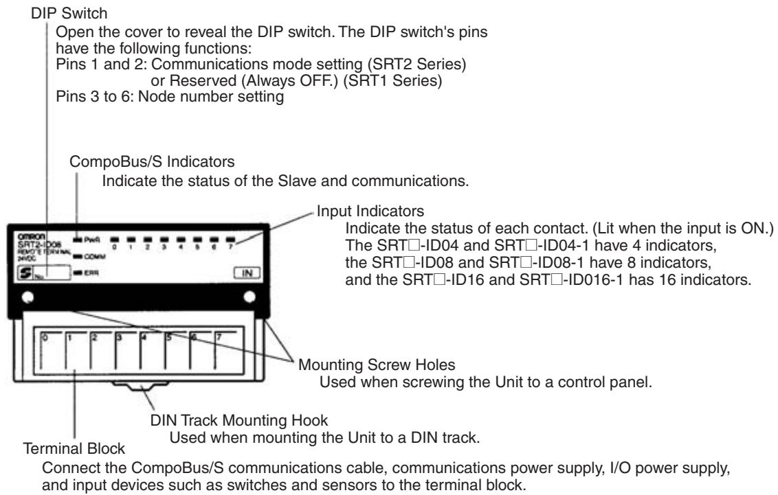
Indicators
The following table shows the meaning of the indicators.
| Indicator | Status | Meaning |
| PWR (green) | ON | The communications power supply is ON. |
| OFF | The communications power supply is OFF. | |
| COMM (yellow) | ON | Normal communications |
| OFF | A communications error has occurred or the Unit is in standby status. | |
| ERR (red) | ON | A communications error has occurred. |
| OFF | Normal communications or the Unit is in standby status. | |
| 0 to 3 (4 inputs) | ON | The corresponding input is ON. |
| 0 to 7 (8 inputs) | OFF | The corresponding input is OFF or the Unit is in standby status. |
| 0 to 15 (16 inputs) (yellow) |
DIP Switch
The DIP switch is located on the left side of the Transistor Remote Terminal, under the cover. Always turn OFF the Slave before changing the node number setting.
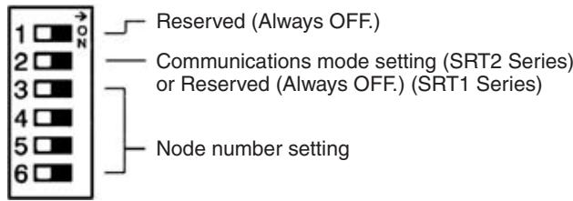
Note 1. Always turn OFF the Slave before changing DIP switch settings.
2. In the SRT1 Series, pin 2 must always be left OFF. Otherwise, the Unit may not function correctly.
Communications Mode Settings (SRT2 Series Only)
The following communications modes are set with pin 2.
| Pin 2 | Communications mode | Communications distance | Communications baud rate | Communications cycle time |
| OFF | High-speed Communications Mode | 100 m max. | 750 kbps | 0.5 or 0.8 ms |
| ON | Long-distance Communications Mode | 500 m max. | 93.75 kbps | 4.0 or 6.0 ms |
The communications mode settings using pin 2 only apply to SRT2-series Slaves and cannot be used with the SRT1-series Slaves, which operate in High-speed Communications Mode at all times.
Note Make sure that the communications mode of the Slave is the same as that of the Master Unit. If the communications modes are not the same, normal communications with the Master Unit will not be possible. The operating status of the Slave can be verified with LED indicators. Refer to 6-5-1 Indicators.
Node Number Settings
Set the node number with pins 3 through 6, as shown in the following table.
| Node number | Pin 3(8) | Pin 4(4) | Pin 5(2) | Pin 6(1) |
| 0 | OFF | OFF | OFF | OFF |
| 1 | OFF | OFF | OFF | ON |
| 2 | OFF | OFF | ON | OFF |
| 3 | OFF | OFF | ON | ON |
| 4 | OFF | ON | OFF | OFF |
| 5 | OFF | ON | OFF | ON |
| 6 | OFF | ON | ON | OFF |
| 7 | OFF | ON | ON | ON |
| 8 | ON | OFF | OFF | OFF |
| 9 | ON | OFF | OFF | ON |
| 10 | ON | OFF | ON | OFF |
| 11 | ON | OFF | ON | ON |
| 12 | ON | ON | OFF | OFF |
| 13 | ON | ON | OFF | ON |
| 14 | ON | ON | ON | OFF |
| 15 | ON | ON | ON | ON |
Note The actual node number setting range depends on the type of PLC in which the Master is mounted as well as the Master's settings. Refer to 2-1 Communications Specifications for details.
Internal Circuits
The following diagram shows the internal circuits for the SRT□-ID04.
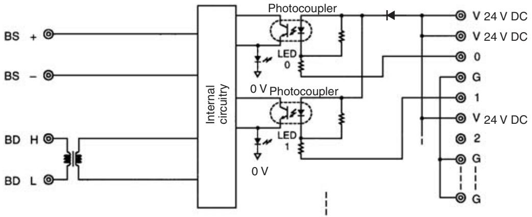
The following diagram shows the internal circuits for the SRT□-ID04-1.
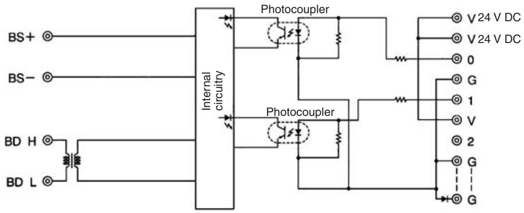
The following diagram shows the internal circuits for the SRT□-ID08.
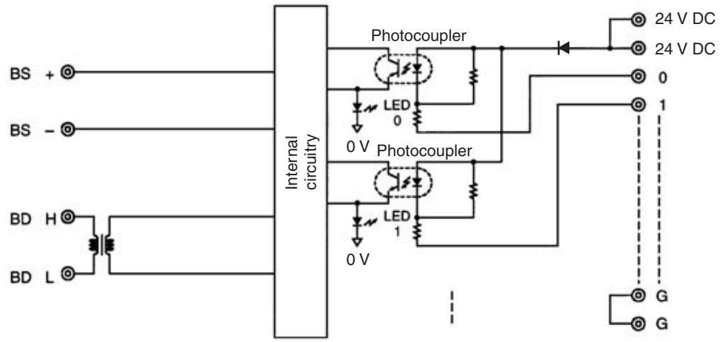
The following diagram shows the internal circuits for the SRT□-ID08-1.
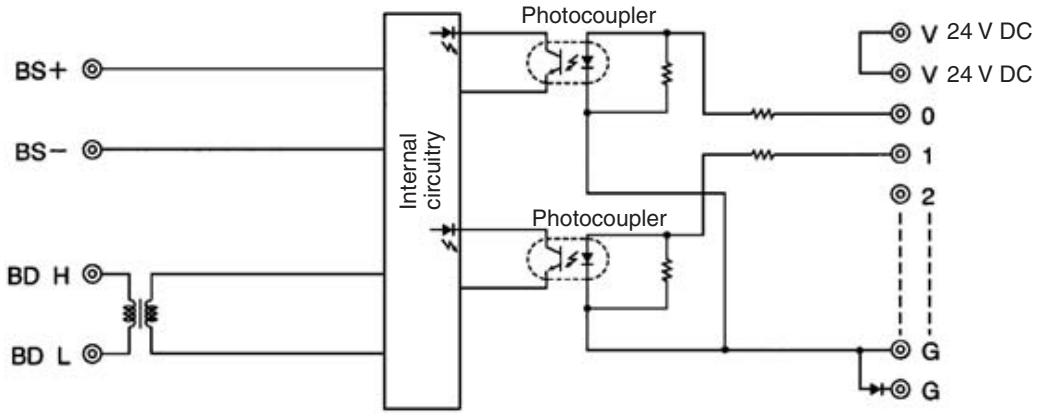
The following diagram shows the internal circuits for the SRT□-ID16.
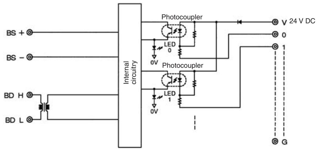
The following diagram shows the internal circuits for the SRT□-ID16-1.
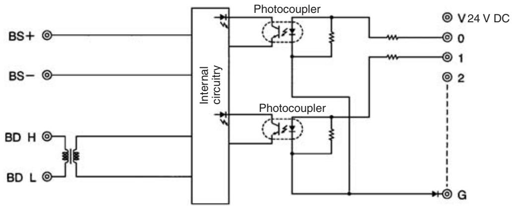
Terminal Arrangement and Wiring
Install the following M3 crimp terminals on the signal wires and connect to the terminal block.
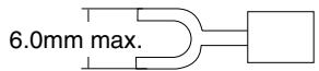
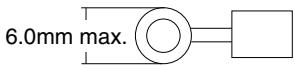
Tighten the terminal block screws to the specified tightening torque of 0.5 N·m.
The following diagram shows the terminal arrangement and wiring for the SRT□-ID04.
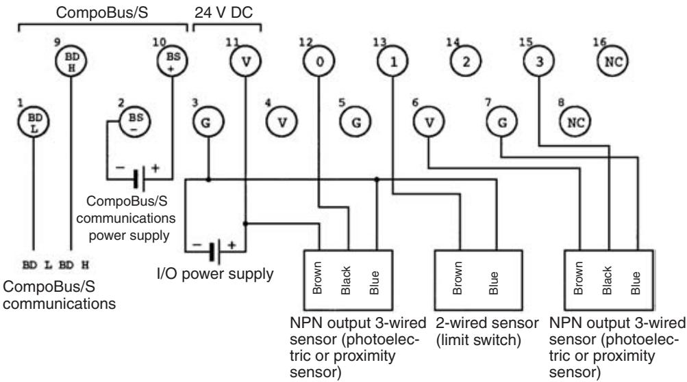
Note The V terminals (terminal numbers 4, 6, and 11) are all connected internally, as are the G terminals (terminal numbers 3, 5, and 7). When I/O power is supplied to terminals 11 and 3, power can be supplied to sensors from terminals 4 and 5 as well as 6 and 7.
When the power supply exceeds 1.0 A, provide an external power supply to the I/O power supply instead of providing the supply from the terminals.
The following diagram shows the terminal arrangement and wiring for the SRT□-ID04-1.
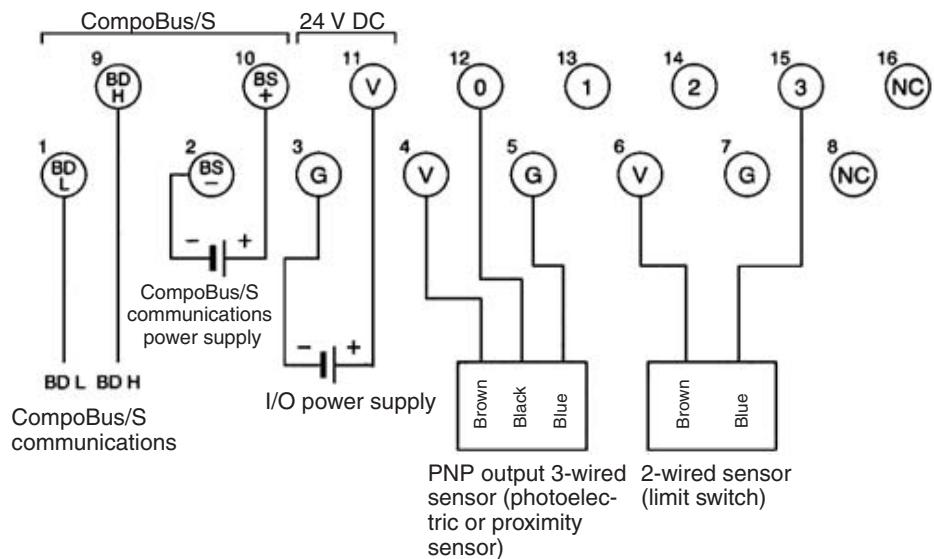
Note The V terminals (terminal numbers 4, 6, and 11) are all connected internally, as are the G terminals (terminal numbers 3, 5, and 7). When I/O power is supplied to terminals 11 and 3, power can be supplied to sensors from terminals 4 and 5 as well as 6 and 7.
When the power supply exceeds 1.0 A, provide an external power supply to the I/O power supply instead of providing the supply from the terminals.
The following diagram shows the terminal arrangement and wiring for the SRT□-ID08.
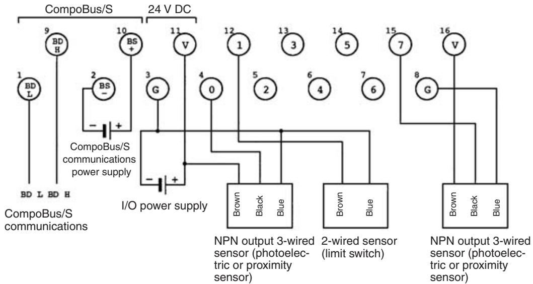
Note The V terminals (terminal numbers 11 and 16) are all connected internally, as are the G terminals (terminal numbers 3 and 8). When I/O power is supplied to terminals 11 and 3, power can be supplied to sensors from terminals 16 and 8.
When the power supply exceeds 1.0 A, provide an external power supply to the I/O power supply instead of providing the supply from the terminals.
The following diagram shows the terminal arrangement and wiring for the SRT□-ID08-1.

Note The V terminals (terminal numbers 11 and 16) are all connected internally, as are the G terminals (terminal numbers 3 and 8). When I/O power is supplied to terminals 11 and 3, power can be supplied to sensors from terminals 16 and 8.
When the power supply exceeds 1.0 A, provide an external power supply to the I/O power supply instead of providing the supply from the terminals.
The following diagram shows the terminal arrangement and wiring for the SRT□-ID16.
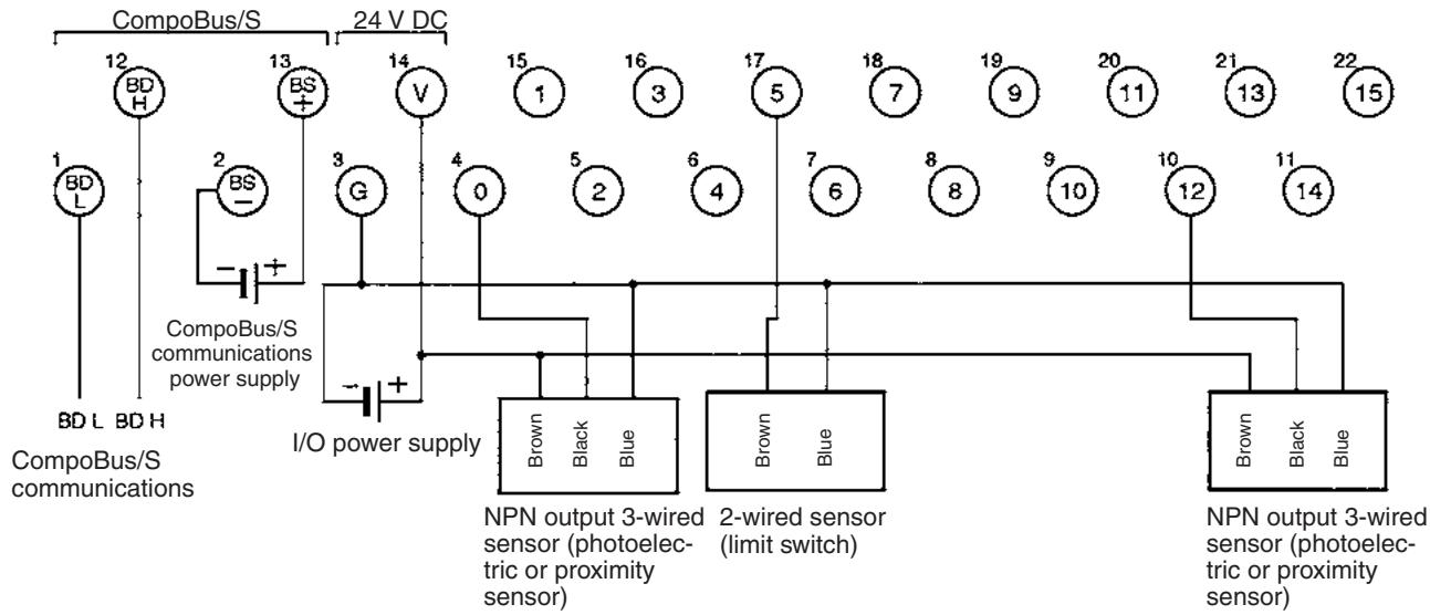
The following diagram shows the terminal arrangement and wiring for the SRT□-ID16-1.
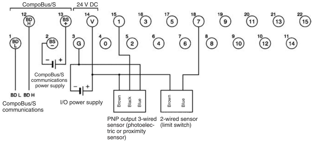
SRT□-ID04/ID04-1/ID08/ ID08-1 Dimensions
The following diagram shows the dimensions for the SRT□-ID04/ID04-1/ID08/ ID08-1. All dimensions are in mm.
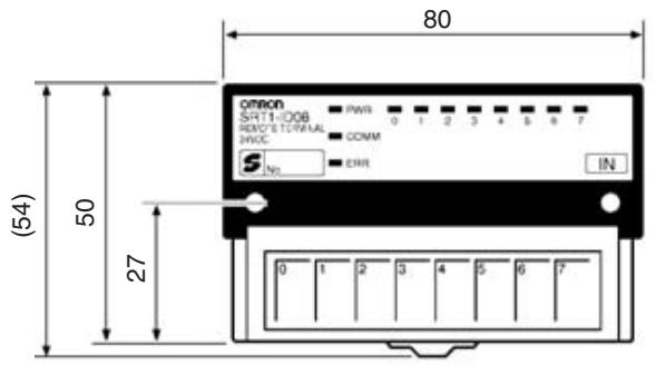
Mounting Holes
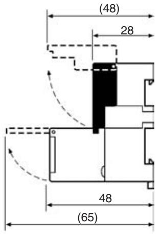
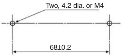
SRT□-ID16/ID16-1 Dimensions
The following diagram shows the dimensions for the SRT□-ID16/ID16-1. All dimensions are in mm.
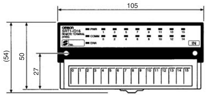
Mounting Holes
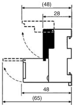
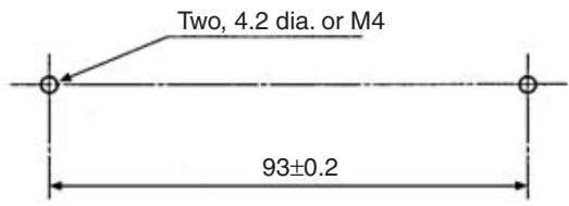
5-1-2 SRT□-ID16T (-1) Remote Terminals with 16 Transistor Inputs (and 3-tier Terminal Blocks)
Specifications
The following tables show the ratings and input specifications for the SRT□-ID16T (-1) Remote Terminal.
Ratings
| Item | Specification |
| Models | SRT1-ID16TSRT1-ID16T-1SRT2-ID16TSRT2-ID16T-1 |
| Input points | SRT□-ID16T: 16 points (NPN)SRT□-ID16T-1: 16 points (PNP) |
| Communications mode | SRT1-ID16T (-1): High-speed Communications ModeSRT2-ID16T (-1): High-speed Communications Modeand Long-distance CommunicationsMode |
| Terminal | 3-tier terminal block (with common I/O terminal for each input point) |
| Power supply type | Multiple power supplies |
| Communications power supply voltage | 14 to 26.4 V DC(Power can be supplied from the communications cable) |
| I/O power supply voltage | 20.4 to 26.4 V DC (24 V DC +10%/_-15%) |
| Current consumption(See note.) | Communications power: 50 mA max. at 24 V DC |
| Noise immunity | ±1.5 kVp-p with a pulse width of 0.1 to 1 μs and a rise time of 1 ns (via impulse noise simulator) |
| Vibration resistance | 10 to 150 Hz, 1.0-mm double amplitude or 70 m/s2 |
| Shock resistance | Malfunction: 200 m/s2 |
| Dielectric strength | 500 V AC (between insulated circuits)1,000 V AC for 1 minute (1-mA sensing current, between charged and uncharged sections) |
| Ambient temperature | Operating: -10 to 55°C (with no icing or condensation)Storage: -25 to 65°C (with no icing or condensation) |
| Ambient humidity | Operating: 25% to 85% (with no condensation)Storage: 25% to 85% (with no condensation) |
| Operating environment | No corrosive gases |
| Mounting method | M4 screws or 35-mm DIN track mounting |
| Mounting strength | 100 N in each direction |
| Terminal strength | Pulling: 100 NTightening: 0.3 to 0.5 N·m |
| Node number settings | The node number is set with a rotary switch. (Set before turning ON the Slave.) |
| Weight | 300 g max. |
Note The current consumption is the value with all 16 points turned ON excluding the current consumption of the external sensor connected to the input Remote Terminal and the current consumption of the load connected to the output Remote Terminal.
Input Specifications
| Item | Specification |
| Input current | 6 mA max./point at 24 V DC 3 mA min./point at 17 V DC |
| ON delay time | 1.5 ms max. |
| OFF delay time | 1.5 ms max. |
| ON voltage | SRT□-ID16T: 15 V DC min. (between each input terminal and V) SRT□-ID16T-1: 15 V DC min. (between each input terminal and G) |
| OFF voltage | SRT□-ID16T: 5 V DC max. (between each input terminal and V) SRT□-ID16T-1: 5 V DC max. (between each input terminal and G) |
| OFF current | 1 mA max. at 24 V DC |
| Insulation method | Photocoupler |
| Input indicators | LED (yellow) |
Slave Components
The following diagram shows the main components of the SRT2-ID16T Transistor Remote Terminal. The functions of these components are described below.
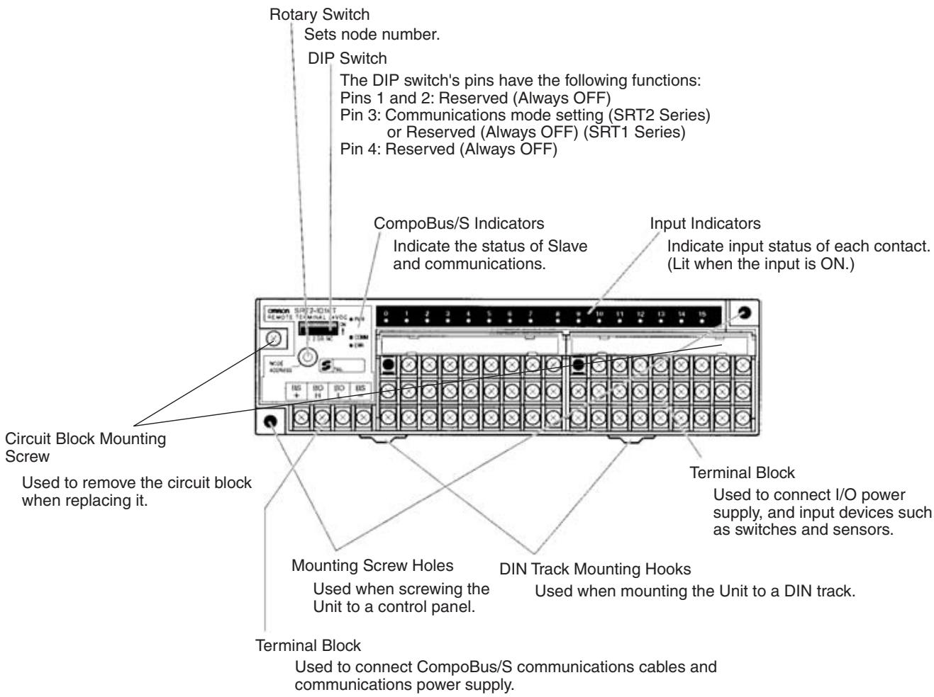
Indicators
The following table shows the meaning of the indicators.
| Indicator | Status | Meaning |
| PWR (green) | ON | The communications power supply is ON. |
| OFF | The communications power supply is OFF. | |
| COMM (yellow) | ON | Normal communications |
| OFF | A communications error has occurred or the Unit is in standby status. | |
| ERR (red) | ON | A communications error has occurred. |
| OFF | Normal communications or the Unit is in standby status. | |
| 0 to 15 (yellow) | ON | The corresponding input is ON. |
| OFF | The corresponding input is OFF or the Unit is in standby status. |
Switch Settings
Rotary and DIP switches are used to enter settings.
Rotary Switch

Node number setting
DIP Switch
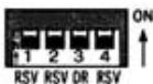
Reserved
(Always OFF)
- Reserved (Always OFF)
Communications mode setting
(SRT2 Series)
or Reserved (Always OFF)
(SRT1 Series)
Note 1. Always turn OFF the Slave before changing DIP switch settings.
- In the SRT1 Series, pin 3 must always be left OFF. Otherwise, the Unit may not function correctly.
- All pins marked "RSV" (reserved) must be left OFF. If any of them is ON, the Unit may not function correctly.
Node Number Settings
The rotary switch specifies node numbers as hexadecimal numbers, as shown below.
| Node number | Setting (Hexadecimal) | Node number | Setting (Hexadecimal) |
| 0 | 0 | 8 | 8 |
| 1 | 1 | 9 | 9 |
| 2 | 2 | 10 | A |
| 3 | 3 | 11 | B |
| 4 | 4 | 12 | C |
| 5 | 5 | 13 | D |
| 6 | 6 | 14 | E |
| 7 | 7 | 15 | F |
Note
- Node numbers of 16-point Slaves are always treated as even numbers. Even if an odd number is specified, the actual node number setting becomes the even number immediately preceding it.
- The actual node number setting range depends on the type of PLC in which the Master is mounted as well as the Master's settings. Refer to 2-1 Communications Specifications for details.
Communications Mode Settings (SRT2 Series Only)
The communications mode is set with pin 3, as shown below.
| Pin 3 | Communications mode | Communications distance | Communications baud rate | Communications cycle time |
| OFF | High-speed Communications Mode | 100 m max. | 750 kbps | 0.5 or 0.8 ms |
| ON | Long-distance Communications Mode | 500 m max. | 93.75 kbps | 4.0 or 6.0 ms |
The communications mode settings using pin 3 only apply to the SRT2-series Slaves and cannot be used with the SRT1-series Slaves, which operate in High-speed Communications Mode at all times.
Internal Circuits
The following diagram shows the internal circuits for the SRT□-ID16T.
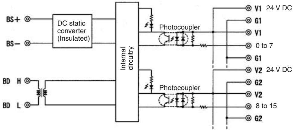
The following diagram shows the internal circuits for the SRT□-ID16T-1.
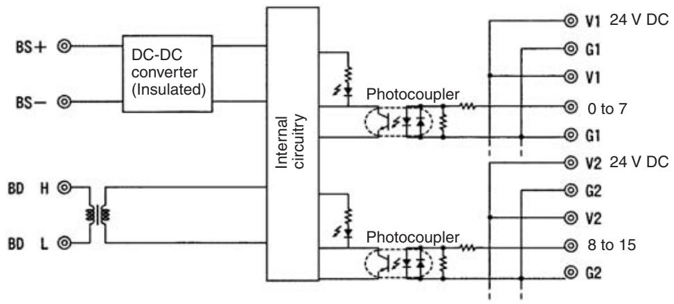
Terminal Arrangement and Wiring
Install the following M3 crimp terminals on the signal wires and connect to the terminal block.
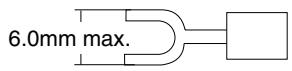
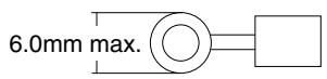
Note Tighten the terminal block screws to the specified tightening torque of 0.5 N·m.
The following diagram shows the terminal arrangement and wiring for the SRT□-ID16T.
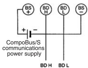
CompoBus/S communications
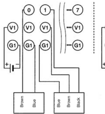
2-wired sensor (limit switch)
NPN output 3-wired sensor (photoelectric sensor or proximity sensor)
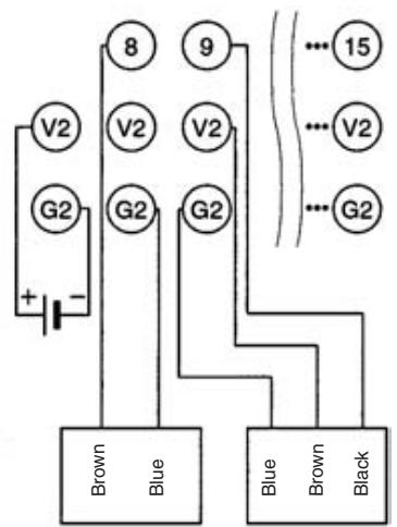
2-wired sensor (limit switch)
NPN output 3-wired sensor (photoelectric sensor or proximity sensor)
The following diagram shows the terminal arrangement and wiring for the SRT□-ID16T-1.
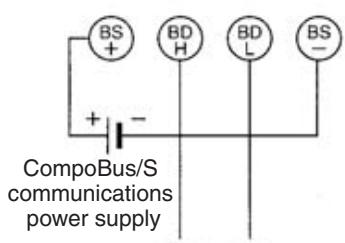
BDH BDL CompoBus/S communications

2-wired sensor (limit switch)
PNP output 3-wired sensor (photoelectric sensor or proximity sensor)
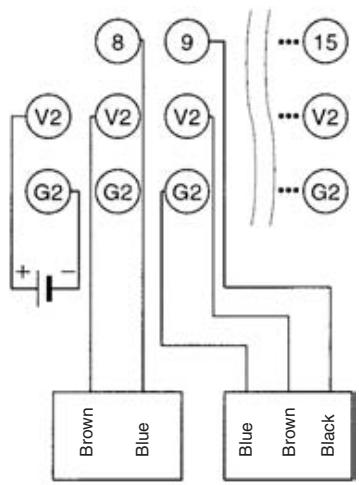
2-wired sensor (limit switch)
PNP output 3-wired sensor (photoelectric sensor or proximity sensor)
Note The V terminals V1 and V2 are not connected internally, and neither are the G terminals G1 and G2 (I/O power supply). Care must be taken when connecting them.
SRT□-ID16T/ID16T-1 Dimensions
The following diagram shows the dimensions for the SRT□-ID16T/ID16T-1. All dimensions are in mm.
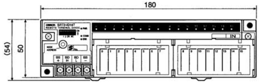
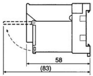
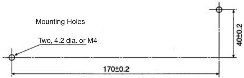
Note The circuit block can be removed by loosening the circuit block mounting screw. Before removing the circuit block for replacement, check that all power supplies, including I/O power supply, to the Unit are turned OFF.
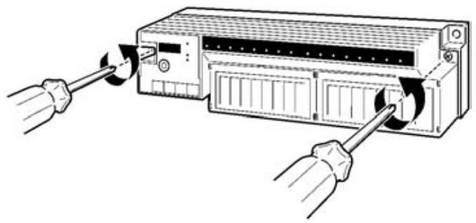
5-1-3 SRT□-OD□(-1) Remote Terminals with 4, 8, or 16 Transistor Outputs
Specifications
The following tables show the ratings and output specifications for the SRT□-OD□(-1).
Ratings
| Item | Specification |
| Models | SRT1-OD04 SRT1-OD08 SRT1-OD16 SRT1-OD04-1 SRT1-OD08-1 SRT1-OD16-1 SRT2-OD04 SRT2-OD08 SRT2-OD16 SRT2-OD04-1 SRT2-OD08-1 SRT2-OD16-1 |
| Output points | SRT□-OD04: 4 points (NPN) SRT□-OD08: 8 points (NPN) SRT□-OD16: 16 points (NPN) SRT□-OD04-1: 4 points (PNP) SRT□-OD08-1: 8 points (PNP) SRT□-OD16-1: 16 points (PNP) |
| Communications mode | SRT1-OD□□ (-1): High-speed Communications Mode SRT2-OD□□ (-1): High-speed Communications Mode and Long-distance Communications Mode |
| Power supply type | Multiple power supplies |
| Communications power supply voltage | 14 to 26.4 V DC (Power can be supplied from the communications cable) |
| I/O power supply voltage | 20.4 to 26.4 V DC (24 V DC +10%/-15%) |
| I/O power supply current | SRT□-OD04 and SRT□-OD04-1: 1 A max. SRT□-OD08 and SRT□-OD08-1: 1 A max. |
| Current consumption (See note.) | Communications power: 50 mA max. at 24 V DC |
| Noise immunity | ±1.5 kVp-p with a pulse width of 0.1 to 1 μs and a rise time of 1 ns (via impulse noise simulator) |
| Vibration resistance | 10 to 55 Hz, 1.0-mm double amplitude |
| Shock resistance | Malfunction: 200 m/s² |
| Dielectric strength | 500 V AC (between insulated circuits) |
| Ambient temperature | Operating: 0 to 55°C (with no icing or condensation) Storage: -20 to 65°C (with no icing or condensation) |
| Ambient humidity | Operating: 35% to 85% (with no condensation) Storage: 20% to 85% (with no condensation) |
| Operating environment | No corrosive gases |
| Mounting method | M4 screws or 35-mm DIN track mounting |
| Mounting strength | Pulling: 50 N Tightening: 1.5 N·m |
| Terminal strength | Pulling: 50 N Tightening: 0.6 to 1.18 N·m |
| Node number settings | The node number is set on a DIP switch. (Set the node number before turning ON the Slave.) |
| Weight | SRT☐-OD04: 80 g max. SRT☐-OD08: 80 g max. SRT☐-OD16: 110 g max. SRT☐-OD04-1: 80 g max. SRT☐-OD08-1: 80 g max. SRT☐-OD16-1: 110 g max. |
Note The current consumption is the value with all 4 and 8 and 16 points turned ON excluding the current consumption of the external sensor connected to the input Remote Terminal and the current consumption of the load connected to the output Remote Terminal.
Output Specifications
| Item | Specification |
| Rated output current | 0.3 A/point |
| Residual voltage | 0.6 V max. SRT□-OD□□: Between each output terminal and G SRT□-OD□□-1: Between each output terminal and V |
| Leakage current | 0.1 mA max. |
| ON delay time | 0.5 ms max. |
| OFF delay time | 1.5 ms max. |
| Insulation method | Photocoupler |
| Output indicators | LED (yellow) |
Slave Components
The following diagram shows the main components of the SRT2-OD08 Transistor Remote Terminal. The functions of these components are described below.
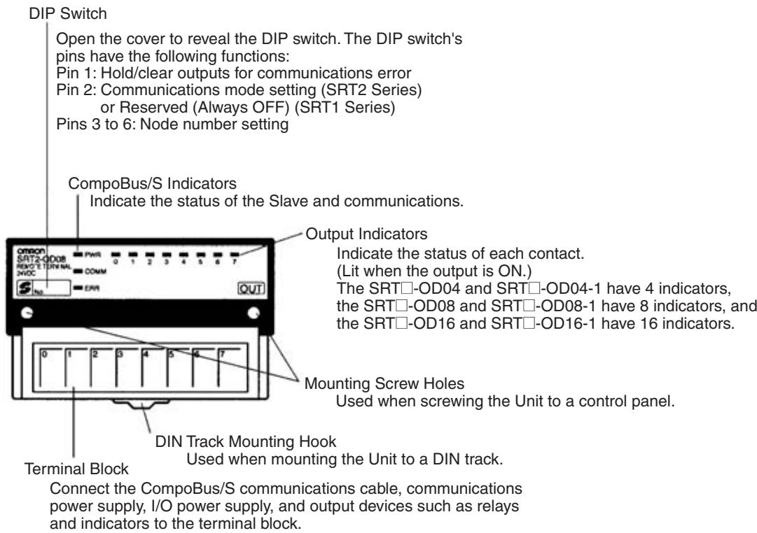
Indicators
The following table shows the meaning of the indicators.
| Indicator | Status | Meaning |
| PWR (green) | ON | The communications power supply is ON. |
| OFF | The communications power supply is OFF. | |
| COMM (yellow) | ON | Normal communications |
| OFF | A communications error has occurred or the Unit is in standby status. | |
| ERR (red) | ON | A communications error has occurred. |
| OFF | Normal communications or the Unit is in standby status. | |
| 0 to 3 (4 outputs) | ON | The corresponding output is ON. |
| 0 to 7 (8 outputs) | OFF | The corresponding output is OFF or the Unit is in standby status. |
| 0 to 15 (16 outputs) (yellow) |
DIP Switch
The DIP switch is located on the left side of the Transistor Remote Terminal, under the cover. Always turn OFF the Slave before changing DIP switch settings.
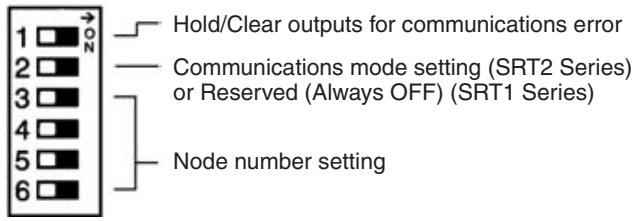
Note 1. Always turn OFF the Slave before changing DIP switch settings.
2. In the SRT1 Series, pin 2 must always be left OFF. Otherwise, the Unit may not function correctly.
Hold/Clear Outputs for Communications Error
Pin 1 is used to set the output data status when a communications error occurs, as shown in the following table.
| Pin 1 (HOLD) | Output setting |
| OFF | Clear output status. |
| ON | Maintain output status. |
Communications Mode Settings (SRT2 Series Only)
The following communications modes are set with pin 2.
| Pin 2 | Communications mode | Communications distance | Communications baud rate | Communications cycle time |
| OFF | High-speed Communications Mode | 100 m max. | 750 kbps | 0.5 or 0.8 ms |
| ON | Long-distance Communications Mode | 500 m max. | 93.75 kbps | 4.0 or 6.0 ms |
The communications mode settings using pin 2 only apply to the SRT2-series Slaves and cannot be used with the SRT1-series Slaves, which operate in High-speed Communications Mode at all times.
Note Make sure that the communications mode of the Slave is the same as that of the Master Unit. If the communications modes are not the same, normal communications with the Master Unit will not be possible. The operating status of the Slave can be verified with LED indicators. Refer to 6-5-1 Indicators.
Node Number Settings
Set the node number with pins 3 through 6, as shown in the following table.
| Node number | Pin 3 (8) | Pin 4 (4) | Pin 5 (2) | Pin 6 (1) |
| 0 | OFF | OFF | OFF | OFF |
| 1 | OFF | OFF | OFF | ON |
| 2 | OFF | OFF | ON | OFF |
| 3 | OFF | OFF | ON | ON |
| 4 | OFF | ON | OFF | OFF |
| 5 | OFF | ON | OFF | ON |
| 6 | OFF | ON | ON | OFF |
| 7 | OFF | ON | ON | ON |
| 8 | ON | OFF | OFF | OFF |
| 9 | ON | OFF | OFF | ON |
| 10 | ON | OFF | ON | OFF |
| 11 | ON | OFF | ON | ON |
| 12 | ON | ON | OFF | OFF |
| 13 | ON | ON | OFF | ON |
| 14 | ON | ON | ON | OFF |
| 15 | ON | ON | ON | ON |
Note The actual node number setting range depends on the type of PLC in which the Master is mounted as well as the Master's settings. Refer to 2-1 Communications Specifications for details.
Internal Circuits
The following diagram shows the internal circuits for the SRT-OD04.
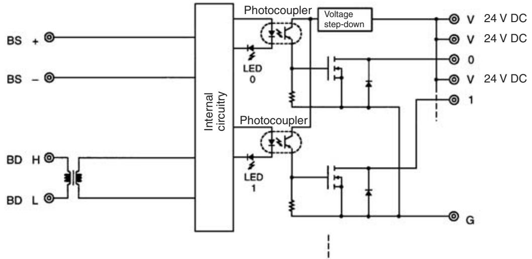
The following diagram shows the internal circuits for the SRT-OD04-1.
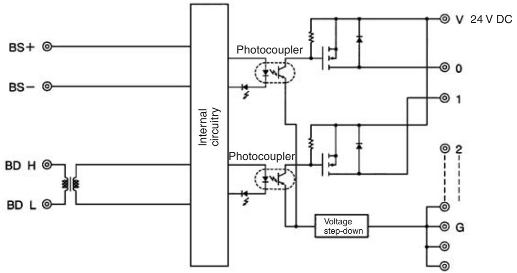
The following diagram shows the internal circuits for the SRT□-OD08.
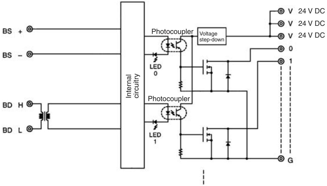
The following diagram shows the internal circuits for the SRT□-OD08-1.
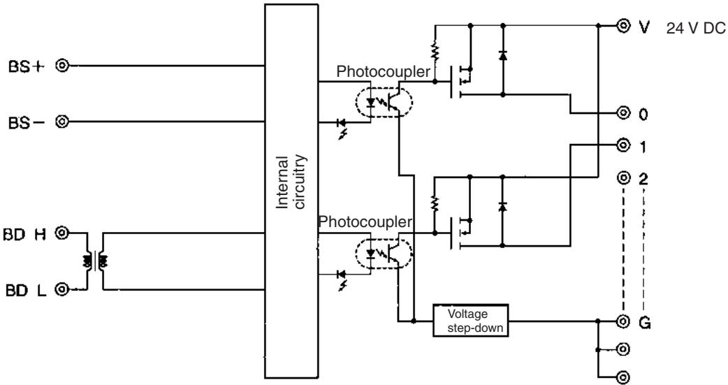
The following diagram shows the internal circuits for the SRT□-OD16.
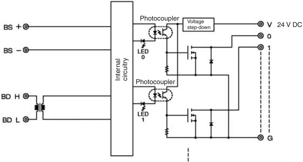
The following diagram shows the internal circuits for the SRT□-OD16-1.
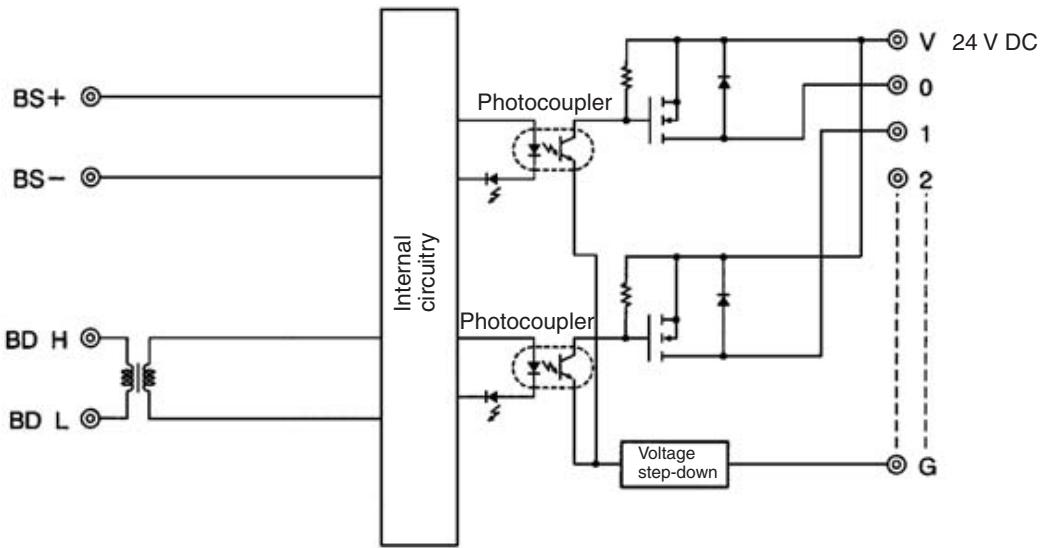
Terminal Arrangement and Wiring
Install the following M3 crimp terminals on the signal wires and connect to the terminal block.
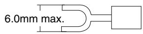
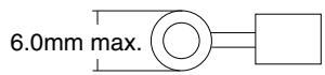
Note Tighten the terminal block screws to the specified tightening torque of 0.5 N·m.
The following diagram shows the terminal arrangement and wiring for the SRT□-OD04.
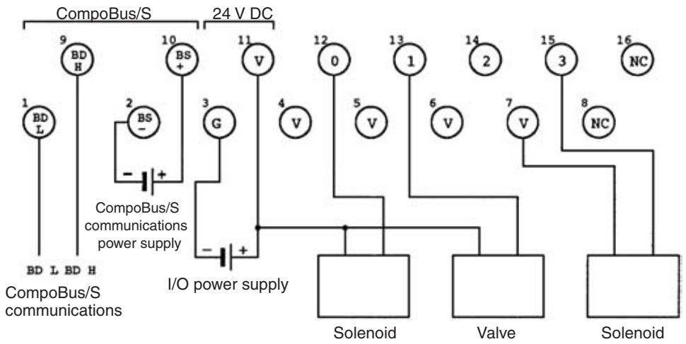
Note
- The V terminals (terminal numbers 4, 5, 6, 7, and 11) are all connected internally. When I/O power is supplied to terminals 11 and 3, power can be supplied to output devices from terminals 4, 5, 6, and 7.
When the power supply exceeds 1.0 A, provide an external power supply to the I/O power supply instead of providing the supply from the terminals. - When inductive loads such as solenoids and valves are used, either use ones with built-in diodes that absorb the back-electromotive force or connect a diode externally.
The following diagram shows the terminal arrangement and wiring for the SRT□-OD04-1.
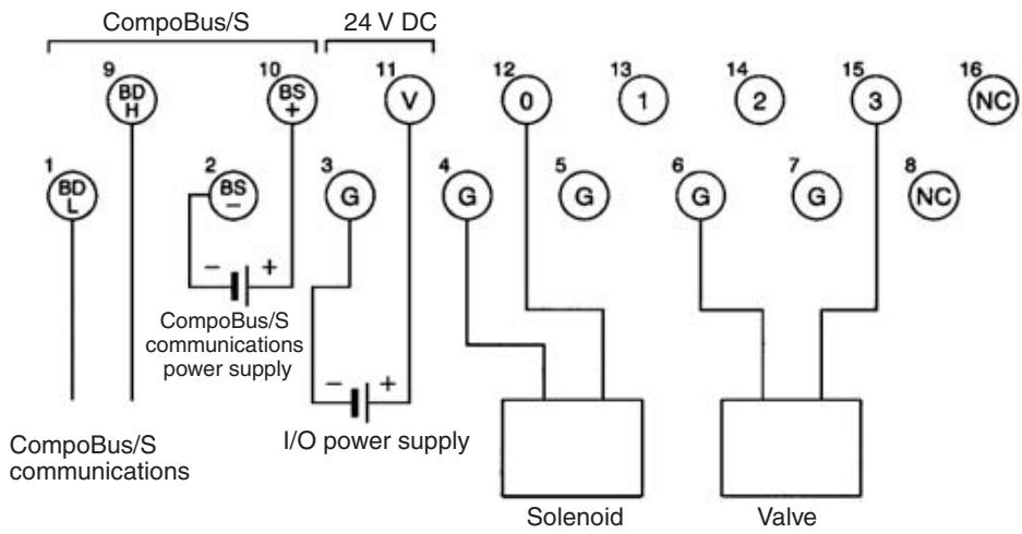
Note
- G terminals (terminal numbers 3 and 4, 5, 6, 7) are all connected internally. When I/O power is supplied to terminals 11 and 3, power can be provided to output devices from terminals 4, 5, 6, and 7.
When the power supply exceeds 1.0A , provide an external power supply to the I/O power supply instead of providing the supply from the terminals.
- When inductive loads such as solenoids and valves are used, either use loads with built-in diodes that absorb the back-electromotive force or connect a diode externally.
The following diagram shows the terminal arrangement and wiring for the SRT□-OD08.
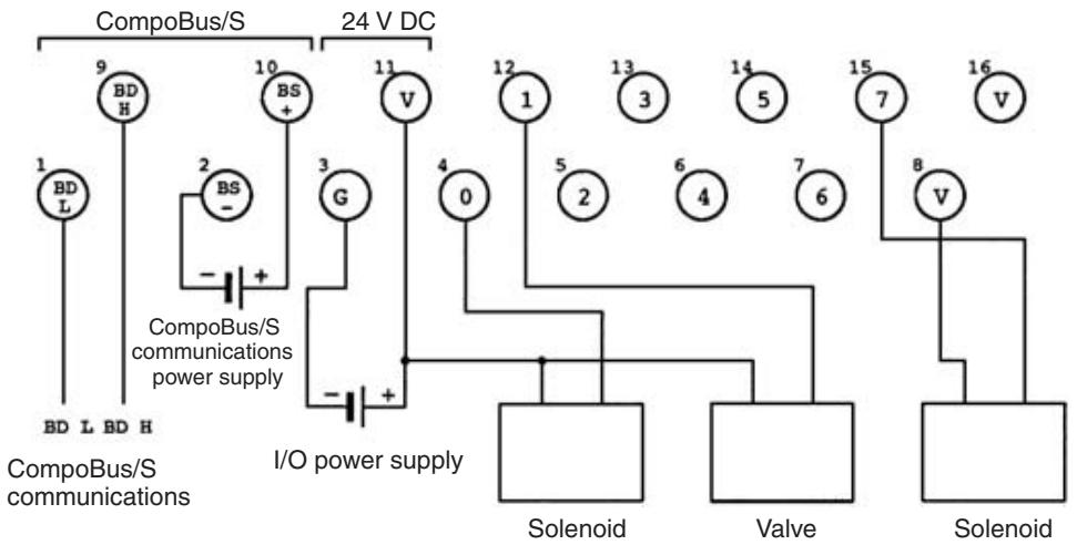
Note
- The V terminals (terminal numbers 11, 8, and 16) are all connected internally. When I/O power is supplied to terminal 11 and 3, power can be supplied to output devices from terminals 8 and 16.
When the power supply exceeds 1.0A , provide an external power supply to the I/O power supply instead of providing the supply from the terminals. - When inductive loads such as solenoids and valves are used, either use ones with built-in diodes that absorb the back-electromotive force or connect a diode externally.
The following diagram shows the terminal arrangement and wiring for the SRT□-OD08-1.
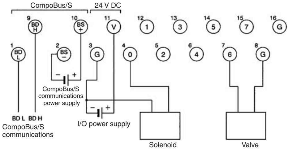
Note
- G terminals (terminal numbers 3 and 8 and 16) are all connected internally. When I/O power is supplied to terminals 11 and 3, power can be provided to output devices from terminal 8 or 16.
When the power supply exceeds 1.0A , provide an external power supply to the I/O power supply instead of providing the supply from the terminals.
- When inductive loads such as solenoids and valves are used, either use loads with built-in diodes that absorb the back-electromotive force or connect a diode externally.
The following diagram shows the terminal arrangement and wiring for the SRT□-OD16.
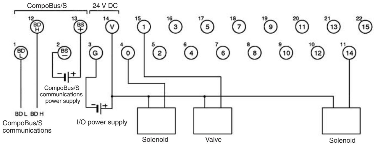
Note When inductive loads such as solenoids and valves are used, either use ones with built-in diodes that absorb the back-electromotive force or connect a diode externally.
The following diagram shows the terminal arrangement and wiring for the SRT□-OD16-1.
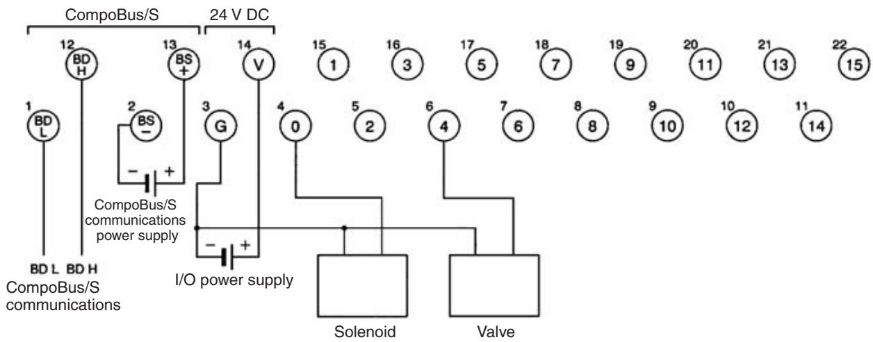
Note When inductive loads such as solenoids and valves are used, either use loads with built-in diodes that absorb the back-electromotive force or connect a diode externally.
SRT□-OD04/OD04-1/
OD08/OD08-1 Dimensions
The following diagram shows the dimensions for the SRT□-OD04/OD04-1/OD08/OD08-1. All dimensions are in mm.
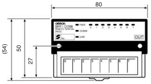
Mounting Holes
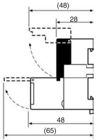
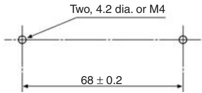
SRT□-OD16/OD16-1
Dimensions
The following diagram shows the dimensions for the SRT□-OD16/OD16-1. All dimensions are in mm.
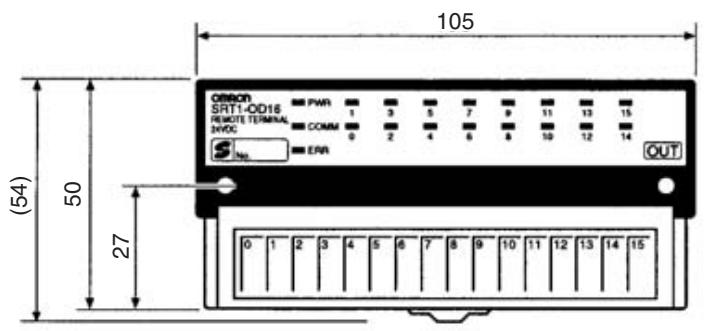
Mounting Holes
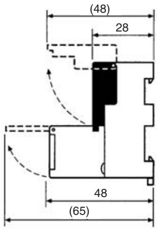
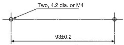
5-1-4 SRT□-OD16T (-1) Remote Terminals with 16 Transistor Outputs (and 3-tier Terminal Blocks)
Specifications
The following tables show the ratings and output specifications for the SRT□-OD16T (-1).
Ratings
| Item | Specification |
| Models | SRT1-OD16T SRT1-OD16T-1 SRT2-OD16T SRT2-OD16T-1 |
| Output points | SRT□-OD16T: 16 points (NPN) SRT□-OD16T-1: 16 points (PNP) |
| Communications mode | SRT1-OD16T (-1): High-speed Communications Mode SRT2-OD16T (-1): High-speed Communications Mode and Long-distance Communications Mode |
| Terminals | 3-tier terminal block (with common I/O terminal for each output point) |
| Power supply type | Multiple power supplies |
| Communications power supply voltage | 14 to 26.4 V DC (Power can be supplied from the communications cable) |
| I/O power supply voltage | 20.4 to 26.4 V DC (24 V DC +10%/_-15%) |
| Current consumption (See note.) | Communications power: 50 mA max. at 24 V DC |
| Noise immunity | ±1.5 kVp-p with a pulse width of 0.1 to 1 μs and a rise time of 1 ns (via impulse noise simulator) |
| Vibration resistance | 10 to 150 Hz, 1.0-mm double amplitude or 70 m/s² |
| Shock resistance | Malfunction: 200 m/s² Destruction: 300 m/s² |
| Dielectric strength | 500 V AC for 1 minute (between insulated circuits) 1,000 V AC for 1 minute (1-mA sensing current between charged and uncharged sections) |
| Ambient temperature | Operating: 10 to 55°C (with no icing or condensation) Storage: -20 to 65°C (with no icing or condensation) |
| Ambient humidity | Operating: 25% to 85% (with no condensation) Storage: 25% to 85% (with no condensation) |
| Operating environment | No corrosive gases |
| Mounting method | M4 screws or 35-mm DIN track mounting |
| Mounting strength | 100 N in each direction |
| Terminal strength | Pulling: 100 N Tightening: 0.3 to 0.5 N • m |
| Node number settings | The node number is set with a rotary switch. (Set the node number before turning ON the Slave.) |
| Weight | Approx. 300 g |
Note The current consumption is the value with all 16 points turned ON excluding the current consumption of the external sensor connected to the input Remote Terminal and the current consumption of the load connected to the output Remote Terminal.
Output Specifications
| Item | Specification |
| Output current | 0.5 A/point |
| Residual voltage | 1.2 V max. (SRT□-OD16T: 0.5 A DC, between each output terminal and G) (SRT□-OD16T-1: 0.5 A DC, between each output terminal and V) |
| Leakage current | 0.1 mA max. |
| ON delay time | 0.5 ms max. |
| OFF delay time | 1.5 ms max. |
| Insulation method | Photocoupler |
| Input indicators | LED (yellow) |
Slave Components
The following diagram shows the main components of the SRT□-ID16T (□) Remote Terminal. The functions of these components are described below.
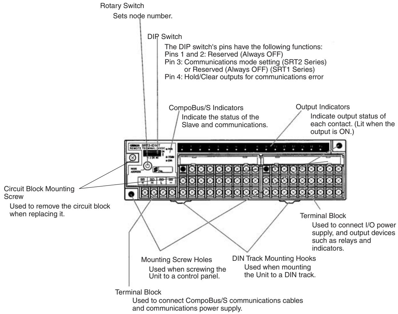
Indicators
The following table shows the meaning of the indicators.
| Indicator | Status | Meaning |
| PWR (green) | ON | The communications power supply is ON. |
| OFF | The communications power supply is OFF. | |
| COMM (yellow) | ON | Normal communications |
| OFF | A communications error has occurred or the Unit is in standby status. | |
| ERR (red) | ON | A communications error has occurred. |
| OFF | Normal communications or the Unit is in standby status. | |
| 0 to 15 (16 points.) (yellow) | ON | The corresponding input is ON. |
| OFF | The corresponding input is OFF or the Unit is in standby status. |
Switch Settings
Rotary and DIP switches are used to enter settings.
Rotary Switch

Node number setting
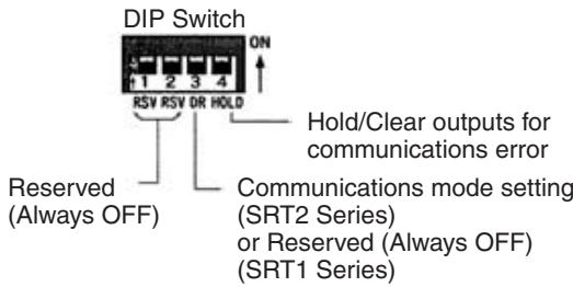
Note 1. Always turn OFF the Slave before changing DIP switch settings.
- In the SRT1 Series, pin 3 must always be left OFF. Otherwise, the Unit may not function correctly.
- All pins marked "RSV" (reserved) must be left OFF. If any of them is ON, the Unit may not function correctly.
Node Number Settings
The rotary switch specifies node numbers as hexadecimal numbers, as shown below.
| Node number | Setting (Hexadecimal) | Node number | Setting (Hexadecimal) |
| 0 | 0 | 8 | 8 |
| 1 | 1 | 9 | 9 |
| 2 | 2 | 10 | A |
| 3 | 3 | 11 | B |
| 4 | 4 | 12 | C |
| 5 | 5 | 13 | D |
| 6 | 6 | 14 | E |
| 7 | 7 | 15 | F |
Note
- Node numbers of 16-point Slaves are always treated as even numbers. Even if an odd number is specified, the actual node number setting becomes the even number immediately preceding it.
- The actual node number setting range depends on the type of PLC in which the Master is mounted as well as the Master's settings. Refer to 2-1 Communications Specifications for details.
Communications Mode Settings (SRT2 Series Only)
The communications mode is set with pin 3, as shown below.
| Pin 3 | Communications mode | Communications distance | Communications baud rate | Communications cycle time |
| OFF | High-speed Communications Mode | 100 m max. | 750 kbps | 0.5 or 0.8 ms |
| ON | Long-distance Communications Mode | 500 m max. | 93.75 kbps | 4.0 or 6.0 ms |
The communications mode settings using pin 3 only apply to the SRT2-series Slaves and cannot be used with the SRT1-series Slaves, which operate in High-speed Communications Mode at all times.
Hold/Clear Outputs for Communications Error
Pin 4 is used to set the output data status when a communications error occurs, as shown in the following table.
| Pin 4 (HOLD) | Setting |
| OFF | Clear output |
| ON | Hold output |
Internal Circuits
The following diagram shows the internal circuits for the SRT-OD16T.
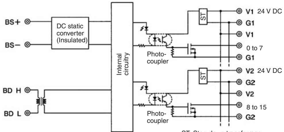
ST: Step-down transformer
The following diagram shows the internal circuits for the SRT-OD16T-1.
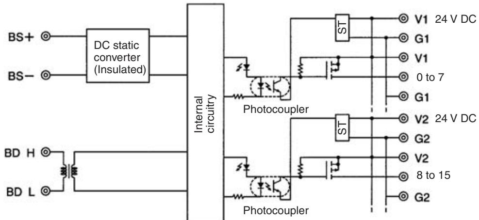
ST: Step-down transformer
Terminal Arrangement and Wiring
Install the following M3 crimp terminals on the signal wires and connect to the terminal block.
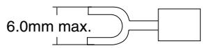
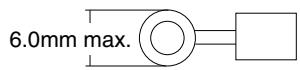
Note Tighten the terminal block screws to the specified tightening torque of 0.5 N·m.
The following diagram shows the terminal arrangement and wiring for the SRT□-OD16T.
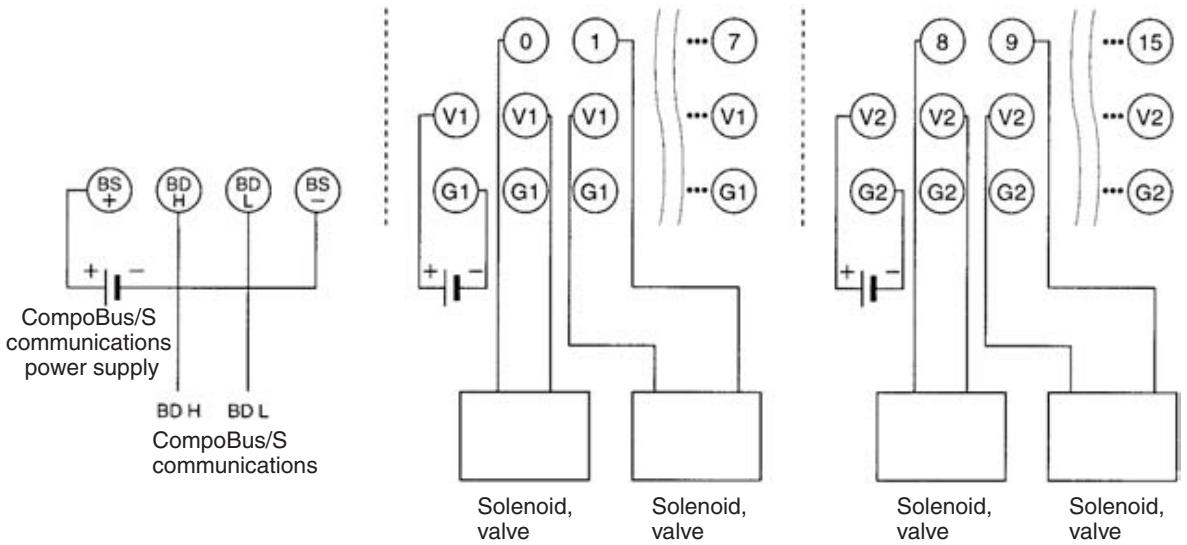
The following diagram shows the terminal arrangement and wiring for the SRT□-OD16T-1.
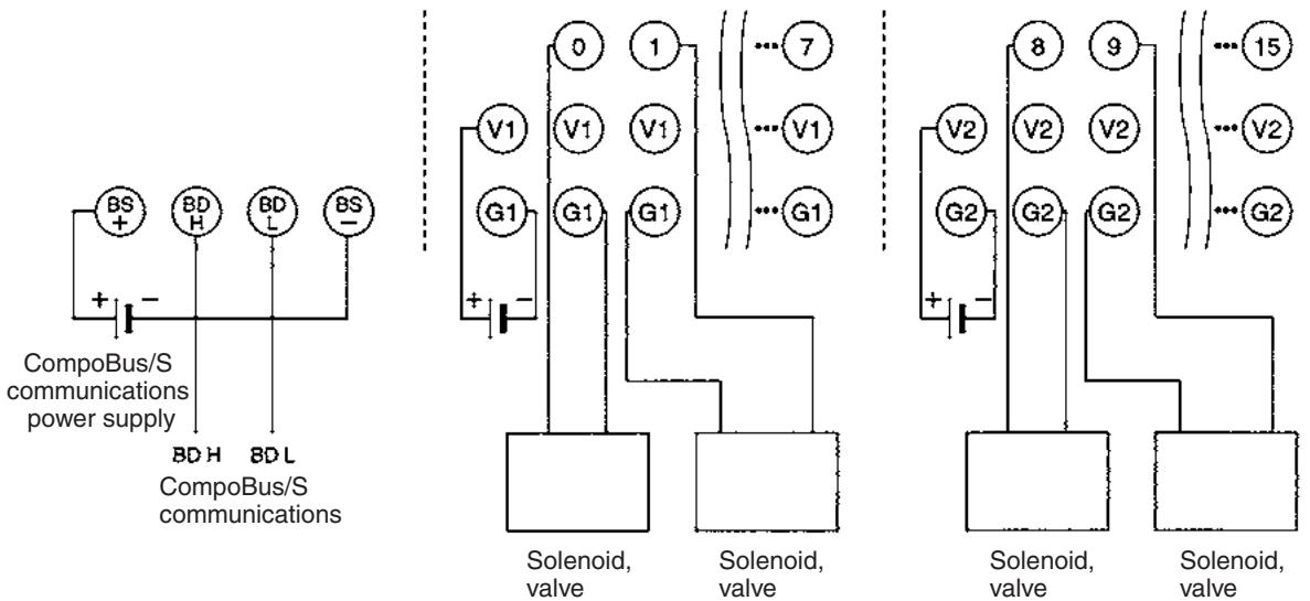
Note
- The V terminals V1 and V2 are not connected internally, and neither are the G terminals G1 and G2 (I/O power supply). Care must be taken when connecting them.
- Do not allow the current between V1 and G1 or between V2 and G2 to exceed 4 A.
- When using inductive loads such as solenoids and valves, either use loads with built-in diodes that absorb the back-electromotive force or connect a diode externally.
SRT-OD16T/OD16T-1 Dimensions
The following diagram shows the dimensions for the SRT□-OD16T/OD16T-1. All dimensions are in mm.
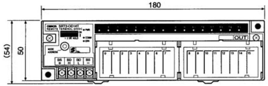

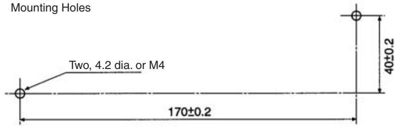
Note The circuit block can be removed by loosening the circuit block mounting screw. Before removing the circuit block for replacement, check that all power supplies, including I/O power supply, to the Unit are turned OFF.
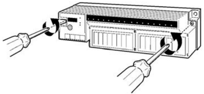
5-1-5 SRT□-MD16T (-1) Remote Terminals with 8 Input and 8 Output Transistors (3-tier Terminal Block)
Specifications
The following tables show the ratings and I/O specifications for the SRT□-MD16T (-1).
Ratings
| Item | Specification |
| Models | SRT1-MD16T SRT1-MD16T-1 SRT2-MD16T SRT2-MD16T-1 |
| I/O points | SRT□-MD16T: 8 inputs, 8 outputs SRT□-MD16T-1: 8 inputs, 8 outputs |
| Communications mode | SRT1-MD16T (-1): High-speed Communications Mode SRT2-MD16T (-1): High-speed Communications Mode and Long-distance Communications Mode |
| Terminals | 3-tier terminal block (with common I/O terminal for each I/O point) |
| Power supply type | Multiple power supplies |
| Communications power supply voltage | 14 to 26.4 V DC (Power can be supplied from the communications cable) |
| I/O power supply voltage | 20.4 to 26.4 V DC (24 V DC +10%/-15%) |
| Current consumption (See note.) | Communications power: 50 mA max. at 24 V DC |
| Noise immunity | ±1.5 kVp-p with a pulse width of 0.1 to 1 μs and a rise time of 1 ns (tested with impulse noise simulator) |
| Vibration resistance | 10 to 150 Hz, 1.0-mm double amplitude or 70 m/s² |
| Shock resistance | Malfunction: 200 m/s² |
| Dielectric strength | 500 V AC (between insulated circuits) |
| Ambient temperature | Operating: -10 to 55°C (with no icing or condensation) Storage: -20 to 65°C (with no icing or condensation) |
| Ambient humidity | Operating: 25% to 85% (with no condensation) Storage: 25% to 85% (with no condensation) |
| Operating environment | No corrosive gases |
| Mounting method | M4 screws or 35-mm DIN track mounting |
| Mounting strength | 100 N in each direction |
| Terminal strength | Pulling: 100 N Tightening: 0.3 to 0.5 N·m |
| Node number settings | The node number is set with a rotary switch. (Set the node number before turning ON the Slave.) |
| Weight | Approx. 300 g |
Note The current consumption is the value with all 16 points turned ON excluding the current consumption of the external sensor connected to the input Remote Terminal and the current consumption of the load connected to the output Remote Terminal.
Input Specifications
| Item | Specification |
| Input current | 6 mA max./point at 24 V DC 3 mA min./point at 17 V DC |
| ON delay time | 1.5 ms max. |
| OFF delay time | 1.5 ms max. |
| ON voltage | SRT□-MD16T: 15 V DC min. (between each input termi- nal and V) SRT□-MD16T-1: 15 V DC min. (between each input ter- minal and G) |
| OFF voltage | SRT□-MD16T: 5 V DC max. (between each terminal and V) SRT□-MD16T-1: 5 V DC max. (between each terminal and G) |
| OFF current | 1 mA max. at 24 V DC |
| Insulation method | Photocoupler |
| Input indicators | LED (yellow) |
Output Specifications
| Item | Specification |
| Output current | 0.5 A/point |
| Residual voltage | 1.2 V max. (SRT□-MD16T: 0.5 A DC, between each output terminal and G) (SRT□-MD16T-1: 0.5 A DC, between each output terminal and V) |
| Leakage current | 0.1 mA max. |
| ON delay time | 0.5 ms max. |
| OFF delay time | 1.5 ms max. |
| Insulation method | Photocoupler |
| Input indicators | LED (yellow) |
Slave Components
The following diagram shows the main components of the SRT□-MD16T (□) Remote Terminal. The functions of these components are described below.
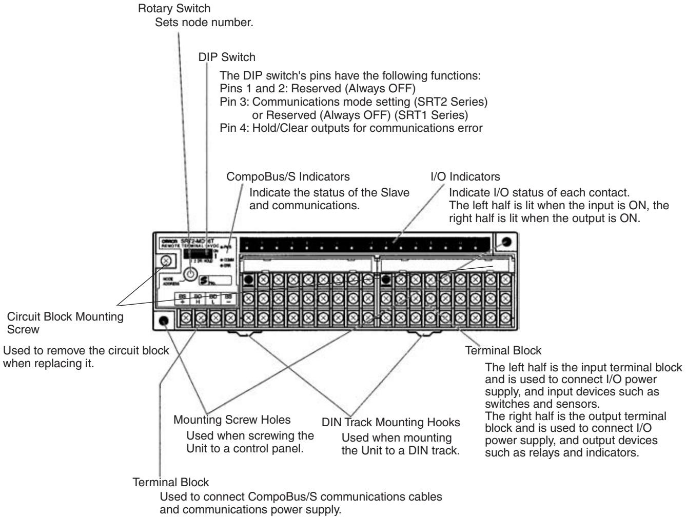
Indicators
The following table shows the meaning of the indicators.
| Indicator | Status | Meaning |
| PWR (green) | ON | The communications power supply is ON. |
| OFF | The communications power supply is OFF. | |
| COMM (yellow) | ON | Normal communications |
| OFF | A communications error has occurred or the Unit is in standby status. | |
| ERR (red) | ON | A communications error has occurred. |
| OFF | Normal communications or the Unit is in standby status. | |
| 0 to 7 (8 inputs) | ON | The corresponding input is ON. |
| 0 to 7 (8 outputs) | OFF | The corresponding input is OFF or the Unit is in standby status. |
| (yellow) |
Switch Settings
Rotary and DIP switches are used to enter settings.
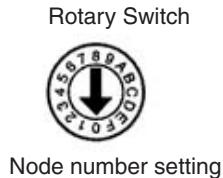
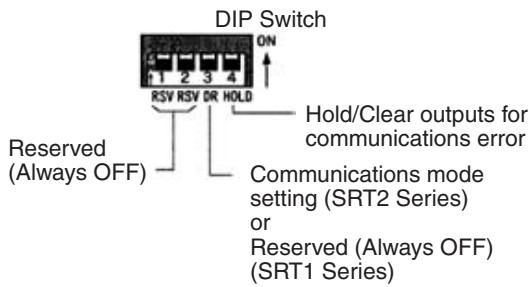
Note 1. Always turn the Slave OFF before changing DIP switch settings.
- In the SRT1 Series, pin 3 must always be left OFF. Otherwise, the Unit may not function correctly.
- All pins marked "RSV" (reserved) must be left OFF. If any of them is ON, the Unit may not function correctly.
Node Number Settings
The rotary switch specifies node numbers as hexadecimal numbers, as shown below.
| Node number | Setting (Hexadecimal) | Node number | Setting (Hexadecimal) |
| 0 | 0 | 8 | 8 |
| 1 | 1 | 9 | 9 |
| 2 | 2 | 10 | A |
| 3 | 3 | 11 | B |
| 4 | 4 | 12 | C |
| 5 | 5 | 13 | D |
| 6 | 6 | 14 | E |
| 7 | 7 | 15 | F |
Note 1. A 16-point I/O Slave is handled as a single 8-point In 8-point Output Slave that possess the same node n
2. The actual node number setting range depends on the type of PLC in which the Master is mounted as well as the Master's settings. Refer to 2-1 Communications Specifications for details.
Communications Mode Settings (SRT2 Series Only)
The communications mode is set with pin 3, as shown below.
| Pin 3 | Communications mode | Communications distance | Communications baud rate | Communications cycle time |
| OFF | High-speed Communications Mode | 100 m max. | 750 kbps | 0.5 or 0.8 ms |
| ON | Long-distance Communications Mode | 500 m max. | 93.75 kbps | 4.0 or 6.0 ms |
The communications mode settings using pin 3 only apply to the SRT2 Series and cannot be used with the SRT1 Series, which operate in High-speed Communications Mode at all times.
Hold/Clear Outputs for Communications Error
Pin 4 is used to set the output data status when a communications error occurs, as shown in the following table.
| Pin 4 (HOLD) | Setting |
| OFF | Clear output |
| ON | Hold output |
Internal Circuits
The following diagram shows the internal circuits for the SRT□-MD16T.
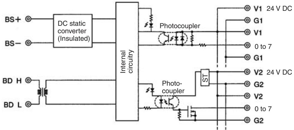
ST: Step-down transformer
The following diagram shows the internal circuits for the SRT□-MD16T-1.
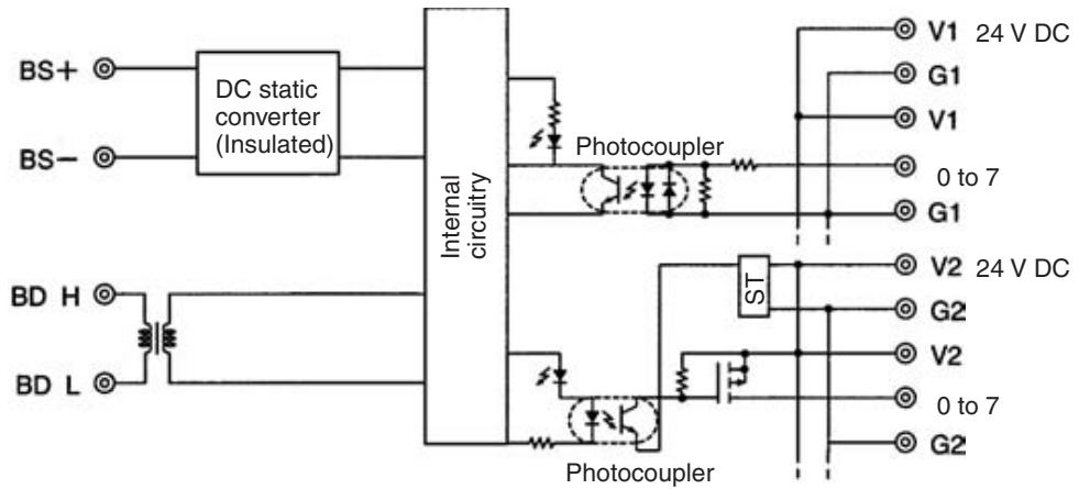
ST: Step-down transformer
Terminal Arrangement and Wiring
Install the following M3 crimp terminals on the signal wires and connect to the terminal block, as shown in the following diagram.

Note Tighten the terminal block screws to the specified tightening torque of 0.5 N·m.
The following diagram shows the terminal arrangement and wiring for the SRT□-MD16T.
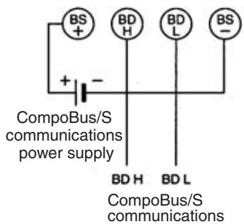
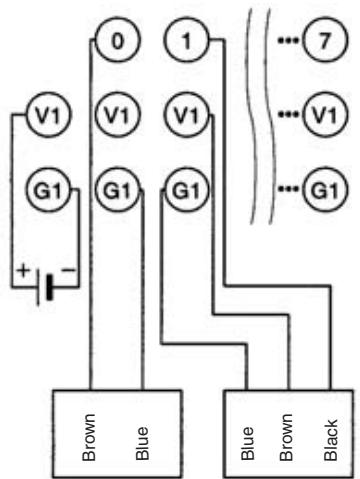
2-wired sensor (limit switch)
NPN output 3-wired sensor (photoelectric sensor or proximity sensor)
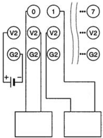
Solenoid, valve
Solenoid, valve
The following diagram shows the terminal arrangement and wiring for the SRT□-MD16T-1.
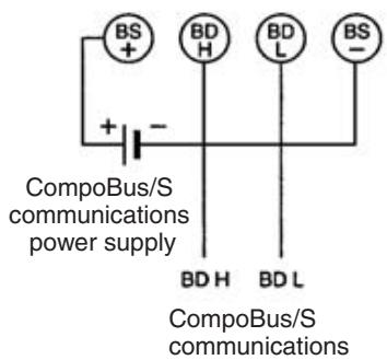
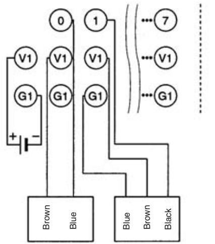
2-wired sensor (limit switch)
PNP output 3-wired sensor (photoelectric sensor or proximity sensor)
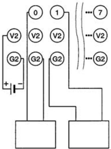
Solenoid, valve
Solenoid, valve
Note
- The V terminals V1 and V2 are not connected internally, and neither are the G terminals G1 and G2 (I/O power supply). Care must be taken when connecting them.
- When inductive loads such as solenoids and valves are used, either use loads with built-in diodes that absorb the back-electromotive force or connect a diode externally.
SRT□-MD16T/MD16T-1 Dimensions
The following diagram shows the dimensions for the SRT□-MD16T/MD16T-1. All dimensions are in mm.
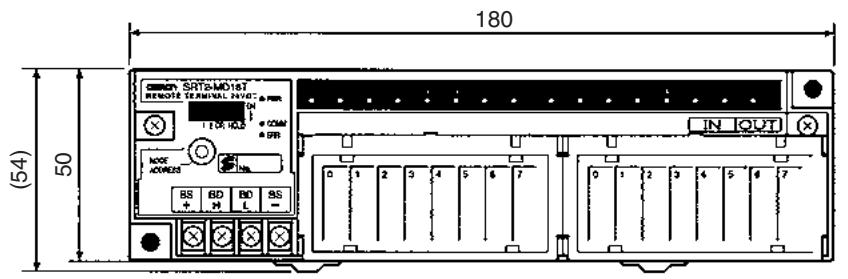
Mounting Holes
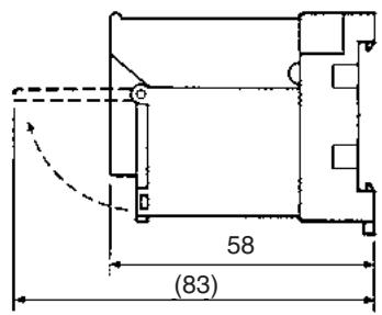
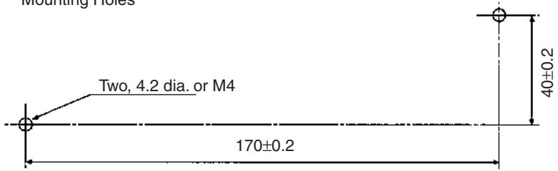
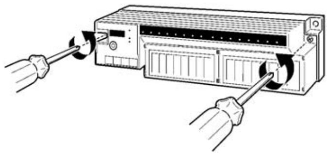
Note The circuit block can be removed by loosening the circuit block mounting screw. Before removing the circuit block for replacement, check that all power supplies, including I/O power supply, to the Unit are turned OFF.
5-1-6 SRT☐-RO☐☐ Remote Terminals with Relay/Power MOS FETs
Specifications
The following tables and graphs show the ratings and output specifications for the SRT□-RO□□□.
Ratings
| Item | Specification |
| Models | SRT1-ROC08 |
| SRT1-ROF08 | |
| SRT1-ROC16 | |
| SRT1-ROF16 | |
| SRT2-ROC08 | |
| SRT2-ROF08 | |
| SRT2-ROC16 | |
| SRT2-ROF16 | |
| Output points | SRT□-ROC08: 8 relay outputs |
| SRT□-ROF08: 8 power MOS FET outputs | |
| SRT□-ROC16: 16 relay outputs | |
| SRT□-ROF16: 16 power MOS FET outputs | |
| (The 16-output Remote Terminals cannot be used with a CQM1-SRM21 Master Unit that is in 4-point mode.) | |
| Communications mode | SRT1-RO□□□: High-speed Communications Mode SRT2-RO□□□: High-speed Communications Mode or Long-distance Communications Mode |
| Power supply type | Local power supply |
| Communications power supply voltage (including I/O power supply) | 20.4 to 26.4 V DC (24 V DC +10%/_-15%) (Power cannot be supplied from the communications cable) |
| Current consumption | Internal circuits: 350 mA max. at 24 V DC (Including relay coil current) |
| Noise immunity | ±1.5 kVp-p with a pulse width of 0.1 to 1 μs and a rise time of 1 ns (via impulse noise simulator) |
| Common terminal current (COM 0, 1, and 2 through 7) | 3 A max. |
| Vibration resistance | 10 to 55 Hz, 1.0-mm double amplitude |
| Shock resistance | Malfunction: 100 m/s² |
| Dielectric strength | 500 V AC (between insulated circuits) 2,000 V AC (between all output terminals and the power supply or between all communications terminals and all different-polarity contacts) |
| Insulation resistance | 20 MΩ min. at 250 V DC (at the same locations as dielectric strength specs.) |
| Ambient temperature | Operating: 0 to 55°C (with no icing or condensation) Storage: -20 to 65°C (with no icing or condensation) |
| Ambient humidity | Operating: 35% to 85% (with no condensation) Storage: 25% to 85% (with no condensation) |
| Operating environment | No corrosive gases |
| Mounting method | M4 screws or 35-mm DIN track mounting |
| Mounting strength | 50 N Track direction: 10 N·m |
| Terminal strength | Pulling: 50 N Tightening: 0.6 to 1.18 N·m |
| Node number settings | The node number is set on a DIP switch. (Set the node number before turning ON the Slave.) |
| Weight | SRT□-ROC08: 145 g max. SRT□-ROF08: 145 g max. SRT□-ROC16: 240 g max. SRT□-ROF16: 240 g max. |
Relay Output Specifications (SRT☐-ROC08, SRT☐-ROC16)
| Item | Specification |
| Applicable relay | G6D-1A (one for each output point) |
| Rated load | 3 A at 250 V AC/3 A at 30 V DC (resistive loads) |
| Rated carry current | 3 A |
| Max. contact voltage | 250 V AC/30 V DC |
| Max. contact current | 3 A |
| Max. switching capacity | 730 VA (AC), 90 W (DC) |
| Min. permissible load | 10 mA at 5 V DCThis value fulfills the P reference value of opening/closing at a rate of 120 times per min. |
| Electrical life expectancy | 100,000 operations min. (3 A at 250 V AC/3 A at 30 V DC, resistive loads at 1800 operations/hour)300,000 operations min. (2 A at 250 V AC/2 A at 30 V DC, resistive loads at 1800 operations/hour) |
| Mechanical life expectancy | 20,000,000 operations min.(at 18,000 operations/hour) |
Power MOS FET Relay Output Specifications (SRT□-ROF08, SRT□-ROF16)
| Item | Specification |
| Applicable relay | G3DZ-2R6PL (one for each output point) |
| Load voltage | 3 to 264 V AC/3 to 125 V DC |
| Load current | 100 μA to 0.3 A |
| Inrush current | 6 A max. (10 ms) |
Note Refer to the PCB Relays Catalog (X33) for the ratings of the G6D and G3DZ.
Reference Data
These graphs are based on actual measured values sampled from the production line. Treat the data as reference values because there is some variation in relay characteristics.
The following graphs show the characteristics for G6D-1A Relays installed in SRT1-ROC08 and SRT1-ROC16 Relay-mounted Remote Terminals.
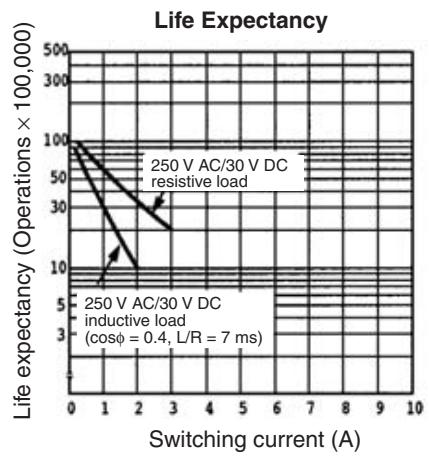
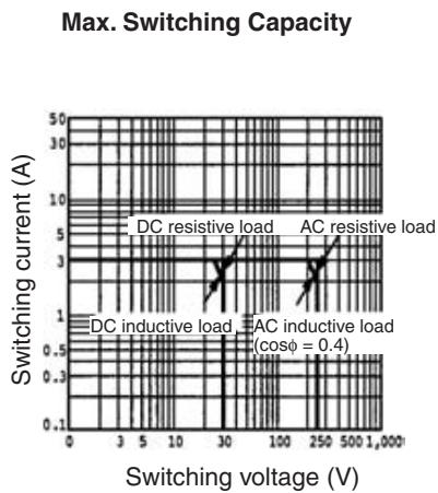
The following graphs show the characteristics for G3DZ-2R6PL Relays installed in SRT1-ROF08 and SRT1-ROF16 Relay-mounted Remote Terminals.
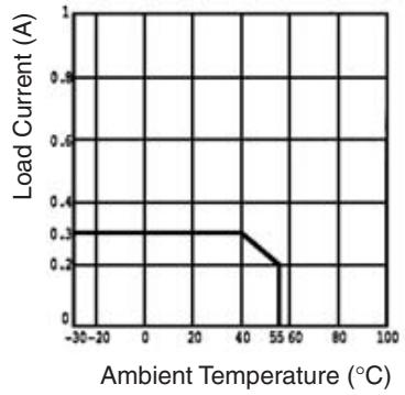
Load Current vs. Ambient Temperature Characteristics
Inrush Current Limit Non-repetitive (Keep the inrush current to half the rated value if it occurs repetitively.)
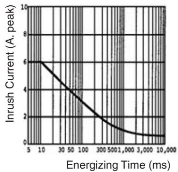
Slave Components
The following diagram shows the main components of the Relay-mounted Remote Terminals. The functions of these components are described below.
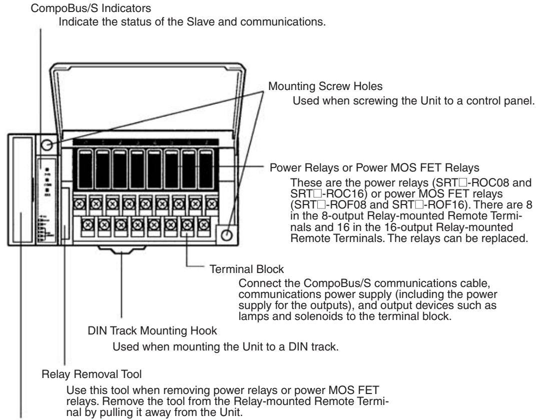
DIP Switch
Open the cover to reveal the DIP switch. The DIP switch's pins have the following functions:
Pin 1: Hold/clear outputs for communications error
Pin 2: Communications setting (SRT2 Series) or Reserved (Always OFF) (SRT1 Series)
Pins 3 to 6: Node number setting
Indicators
The following table shows the meaning of the indicators.
| Indicator | Status | Meaning |
| PWR (green) | ON | The communications power supply is ON. |
| OFF | The communications power supply is OFF. | |
| COMM (yellow) | ON | Normal communications |
| OFF | A communications error has occurred or the Unit is in standby status. | |
| ERR (red) | ON | A communications error has occurred. |
| OFF | Normal communications or the Unit is in standby status. | |
| 0 to 7 (8 outputs) | ON | The corresponding output is ON. |
| 0 to 15 (16 outputs) (yellow) | OFF | The corresponding output is OFF or the Unit is in standby status. |
DIP Switch
The DIP switch is located on the left side of the Relay-mounted Remote Terminal, under the cover. Always turn OFF the Slave before changing DIP switch settings.
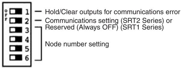
Note 1. Always turn OFF the Slave before changing DIP switch settings.
2. In the SRT1 Series, pin 2 must always be left OFF. Otherwise, the Unit may not function correctly.
Hold/Clear Outputs for Communications Error
Pin 1 is used to set the output data status when a communications error occurs, as shown in the following table.
| Pin 1 (HOLD) | Output setting |
| OFF | Clear output status. |
| ON | Maintain output status. |
Communications Mode Setting (SRT2 Series Only)
The following communications modes are set with pin 2.
| Pin 2 | Communications mode | Communications distance | Communications baud rate | Communications cycle time |
| OFF | High-speed Communications Mode | 100 m max. | 750 kbps | 0.5 or 0.8 ms |
| ON | Long-distance Communications Mode | 500 m max. | 93.75 kbps | 4.0 or 6.0 ms |
The communications mode settings using pin 2 only apply to the SRT2-series Slaves and cannot be used with the SRT1-series Slaves, which operate in High-speed Communications Mode at all times.
Note Make sure that the communications mode of the Slave is the same as that of the Master Unit. If the communications modes are not the same, normal communications with the Master Unit will not be possible. The operating status of the Slave can be verified with LED indicators. Refer to 6-5-1 Indicators.
Node Number Settings
Set the node number with pins 3 through 6, as shown in the following table.
| Node number | Pin 3 (8) | Pin 4 (4) | Pin 5 (2) | Pin 6 (1) |
| 0 | OFF | OFF | OFF | OFF |
| 1 | OFF | OFF | OFF | ON |
| 2 | OFF | OFF | ON | OFF |
| 3 | OFF | OFF | ON | ON |
| 4 | OFF | ON | OFF | OFF |
| 5 | OFF | ON | OFF | ON |
| 6 | OFF | ON | ON | OFF |
| 7 | OFF | ON | ON | ON |
| 8 | ON | OFF | OFF | OFF |
| 9 | ON | OFF | OFF | ON |
| 10 | ON | OFF | ON | OFF |
| 11 | ON | OFF | ON | ON |
| 12 | ON | ON | OFF | OFF |
| 13 | ON | ON | OFF | ON |
| 14 | ON | ON | ON | OFF |
| 15 | ON | ON | ON | ON |
Note The actual node number setting range depends on the type of PLC in which the Master is mounted as well as the Master's settings. Refer to 2-1 Communications Specifications for details.
Internal Circuits
The following diagram shows the internal circuits for all of the Relay/Power MOS FET Relay-mounted Remote Terminals (SRT□-ROC08/ROC16 and SRT□-ROF08/ROF16).
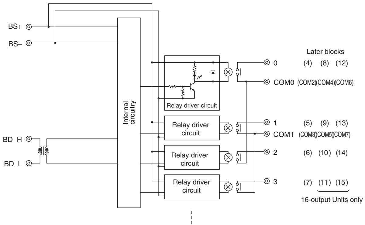
Terminal Arrangement and Wiring
Install the following M3 crimp terminals on the signal wires and connect to the terminal block.

Note Tighten the terminal block screws to the specified tightening torque of 0.5 N·m.
The following diagram shows the terminal arrangement and wiring for the 8-output Relay-mounted Remote Terminals (SRT□-ROC08 and SRT□-ROF08).
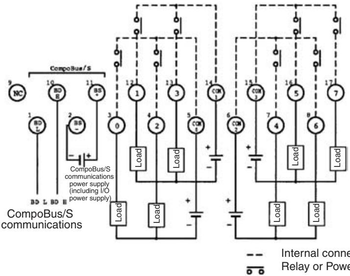
Note The BS + and BS- terminals of the communications power supply (including the I/O power supply) cannot be supplied from the communications cable, so they must be supplied separately.
The following diagram shows the terminal arrangement and wiring for the 16-output Relay-mounted Remote Terminals (SRT□-ROC16 and SRT□-ROF16).
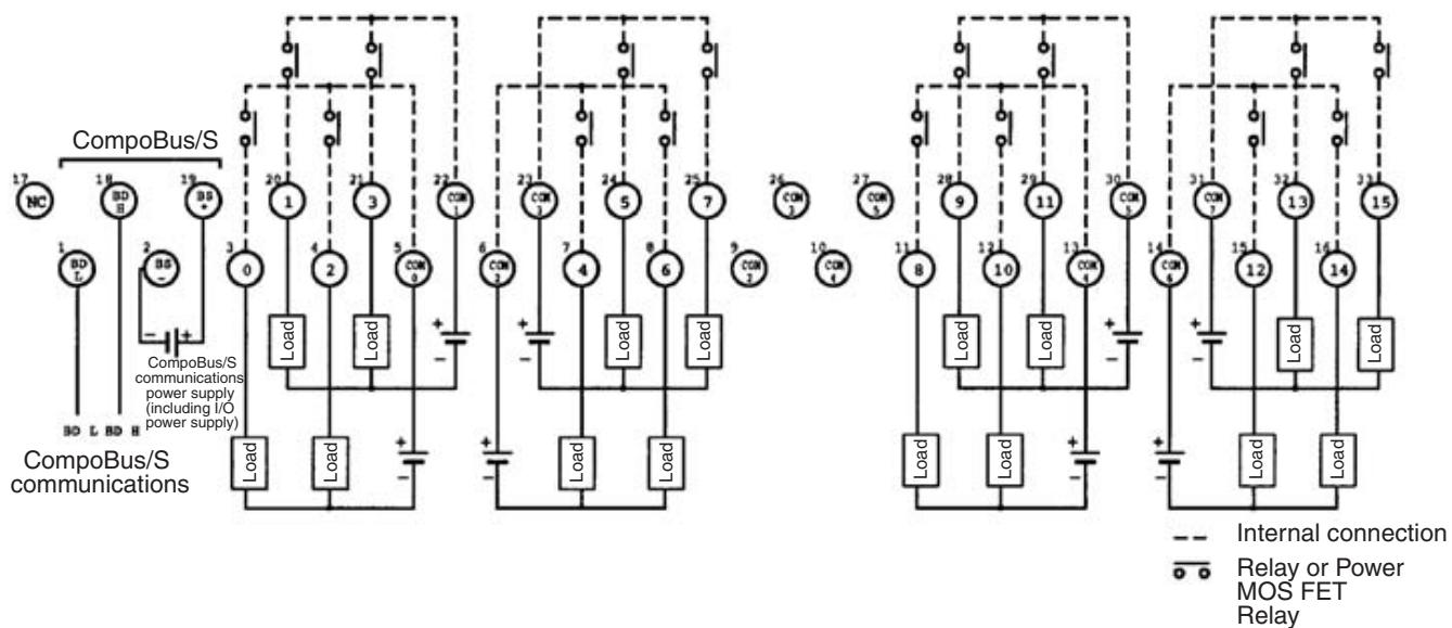
Note
- There are two each of the COM2 and COM3 terminals, and two each of the COM4 and COM5 terminals. When power is supplied to all the terminals at once, wiring the COM terminals can be simplified by short-circuiting the central COM terminals.
- The maximum carry current for each terminal from COM0 to COM7 is 3 A. When power is supplied to all the terminals at once, the total carry current for the COM terminals connected together must not exceed 3 A.
- The BS + and BS- terminals of the communications power supply (including the I/O power supply) cannot be supplied from the communications cable, so they must be supplied separately.
SRT□-ROC08/ROF08 Dimensions
The following diagram shows the dimensions for the 8-output Relay-mounted Remote Terminals (SRT□-ROC08 and SRT□-ROF08). All dimensions are in mm.
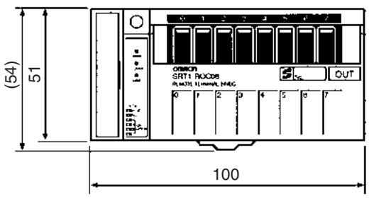
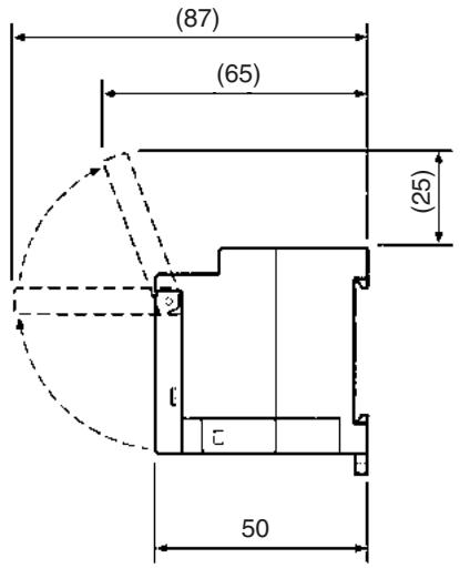
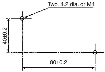
Mounting Holes
SRT□-ROC16/ROF16
Dimensions
The following diagram shows the dimensions for the 16-output Relay-mounted Remote Terminals (SRT□-ROC16 and SRT□-ROF16). All dimensions are in mm.
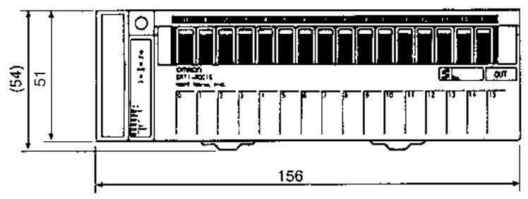
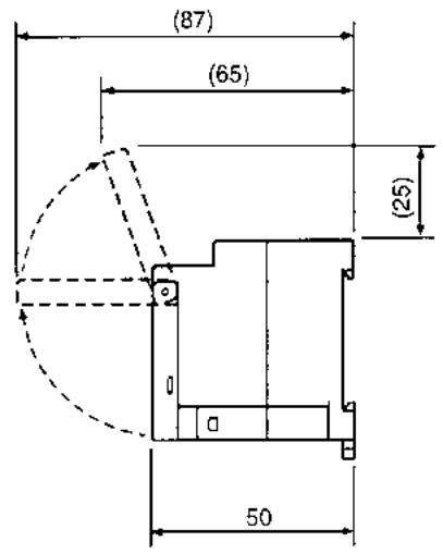
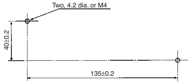
Mounting Holes
5-2 Connector Terminals
5-2-1 SRT2-VID□□□ (-1) Connector Terminals with 8 Input or 16 Output Transistors
Specifications
The following tables show the ratings and input specifications for the SRT2-VID□□□(-1).
Ratings
| Item | Specification | |
| Models | SRT2-VID08S SRT2-VID08S-1 SRT2-VID16ML SRT2-VID16ML-1 | |
| Input points/Connection type | SRT2-VID08S: 8 points (NPN)/ Cable connector input SRT2-VID08S-1: 8 points (PNP)/ Cable connector input SRT2-VID16ML: 16 points (NPN)/ MIL connector input SRT2-VID16ML-1: 16 points (PNP)/ MIL connector input | |
| Item | Specification | |
| Connection | Input | SRT2-VID08S (-1): By XS8A-0441 Connector or XS8A-0442 Con- nector (both sold separately) SRT2-VID16ML (-1): By XG4M-2030-T MIL Connector (sold sepa- rately), or G79-050C, G79-025C, G79-150C and G79-125C MIL-compatible Cables (all sold se- arately) |
| Communications power | By communications connector (included as stan- dard) | |
| I/O power | ||
| Power supply type | Multiple power supplies | |
| Communications power supply voltage | 14 to 26.4 V DC (Power can be supplied from the communications cable) | |
| I/O power supply voltage | 20.4 to 26.4 V DC (24 V DC +10%/−15%) | |
| I/O power supply current | Cable connector: 2.4 A max. MIL connector: 2.0 A max. | |
| Current consumption (See note.) | Communications power: 50 mA max. at 24 V DC | |
| Noise immunity | ±1.5 kVp-p with a pulse width of 0.1 to 1 μs and a rise time of 1 ns (tested with impulse noise simula- tor) | |
| Vibration resistance | 10 to 150 Hz, 1.0-mm double amplitude or 70 m/s2 | |
| Shock resistance | 200 m/s2 | |
| Dielectric strength | 500 V AC (between insulated circuits) | |
| Ambient temperature | Operating: -10 to 55°C (with no icing or condensation) Storage: -25 to 65°C (with no icing or condensation) | |
| Ambient humidity | Operating: 25% to 85% (with no condensation) Storage: 25% to 85% (with no condensation) | |
| Operating environment | No corrosive gases | |
| Standard accessory | 1 communications connector Note: Mounting Brackets A (SRT2-ATT01) and B (SRT2-ATT02) are sold separately. | |
| Mounting strength | Pulling: 100 N in each direction. (When mounted with Mounting Bracket B: 40 N) | |
| Terminal strength | Pulling: As stated below. Communications connector: 100 N Cable connector: 40 N MIL connector: 100 N Tightening: 0.25 N • m (for communications con- nector) | |
| Node number settings | The node number is set on a DIP switch. (Set the node number before turning ON the Slave.) | |
| Weight | Approx. 75 g | |
Note This is the current consumption when all the maximum simultaneous input points are ON, excluding the current consumption of external sensors.
Input Specifications
| Item | VID08S/VID08S-1 | VID16ML/VID16ML-1 |
| Input current | 6 mA max./point at 24 V DC3 mA min./point at 17 V DC | |
| ON delay time | 1.5 ms max. | |
| OFF delay time | 1.5 ms max. | |
| ON voltage | VID08S/VID16ML:15 V DC min. (between each input terminal and V)VID08S-1/VID16ML-1:15 V DC min. (between each input terminal and G) | |
| OFF voltage | VID08S/VID16ML:5 V DC max. (between each input terminal and V)VID08S-1/VID16ML-1:5 V DC max. (between each input terminal and G) | |
| OFF current | 1 mA max. | |
| Insulation method | Photocoupler | |
| Max. simulta-neous input points | 8 points | 12 points |
| Number of circuits | 8 points/single common circuit | 16 points/single common cir-cuit |
Simultaneous Input Points and Installation Spacing
For Connector Terminals with transistor inputs, the ambient operating temperature places a limit on the maximum number of points that can be turned ON simultaneously. In addition, when installing Connector Terminals, care must be taken to provide adequate space between them to prevent overheating.
As shown in the graphs below, the spacing of Connector Terminals varies according to the Connector Terminal type, the ambient operating temperature, and the number of simultaneous input points. Make the distance between Connector Terminals greater than that shown in the graphs.
For example, if SRT2-VID16ML Connector Terminals are to be mounted vertically where the ambient operating temperature will be 55^ and the maximum number of simultaneous input points will be 8, the spacing of Connector Terminals should be at least 10mm .
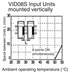
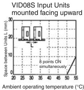
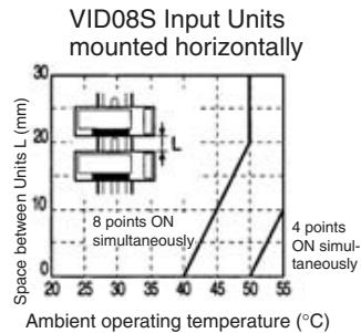
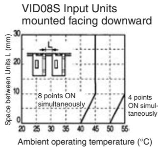
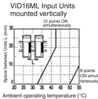
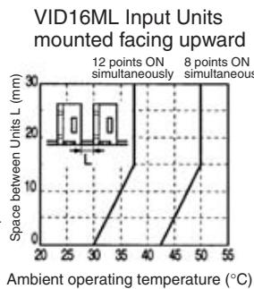
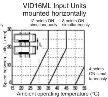
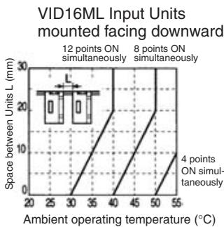
Slave Components
The following diagram shows the main components of the SRT2-VID□□□(-□)Connector Terminals with transistor inputs. The functions of these components are described below.
Models with Sensor Connectors
SRT2-VID08S/VID08S-1
Communications Connector
Used to connect CompoBus/S communications data (BD H, BD L), communications power supply, and I/O power supply (see page 256). One compatible connector is provided as standard.
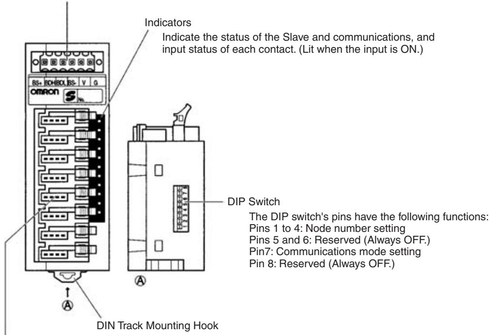
Input Connector (Cable Connector)
Connect 8 inputs with cable connector (see page 67).
The XS8A-0441 Cable Connector (compatible wire size: 0.3 to 0.5mm^2 ) and the
XS8A-0442 Cable Connector (compatible wire size: 0.14 to 0.2mm^2 ) are sold separately.
Models with MIL Connectors
SRT2-VID16ML/VID16ML-1
Communications Connector
Used to connect CompoBus/S communications data (BD H, BD L), communications power
supply and I/O power supply (see page 256).
One compatible connector is provided as standard.
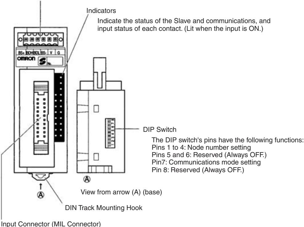
Connect 16 inputs with MIL Connector (see page 258).
XG4M-2030-T MIL Connector and compatible cable are sold separately.
Indicators
The following table shows the meaning of the indicators.
| Indicator | Status | Meaning |
| PWR (green) | ON | The communications power supply is ON. |
| OFF | The communications power supply is OFF. | |
| COMM (yellow) | ON | Normal communications |
| OFF | A communications error has occurred or the Unit is in standby status. | |
| ERR (red) | ON | A communications error has occurred. |
| OFF | Normal communications or the Unit is in standby status. | |
| 0 to 7 (8 inputs) | ON | The corresponding input is ON. |
| 0 to 15 (16 inputs) | OFF | The corresponding input is OFF or the Unit is in standby status. |
DIP Switch
The DIP switch is located on the base of the Connector Terminal.
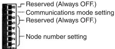
Note Always turn OFF the Slave before changing DIP switch settings.
Node Number Settings
Set the node number with pins 1 through 4, as shown in the following table.
| Node number | Pin 4 (8) | Pin 3 (4) | Pin 2 (2) | Pin 1 (1) |
| 0 | OFF | OFF | OFF | OFF |
| 1 | OFF | OFF | OFF | ON |
| 2 | OFF | OFF | ON | OFF |
| 3 | OFF | OFF | ON | ON |
| 4 | OFF | ON | OFF | OFF |
| 5 | OFF | ON | OFF | ON |
| 6 | OFF | ON | ON | OFF |
| 7 | OFF | ON | ON | ON |
| 8 | ON | OFF | OFF | OFF |
| 9 | ON | OFF | OFF | ON |
| 10 | ON | OFF | ON | OFF |
| 11 | ON | OFF | ON | ON |
| 12 | ON | ON | OFF | OFF |
| 13 | ON | ON | OFF | ON |
| 14 | ON | ON | ON | OFF |
| 15 | ON | ON | ON | ON |
Communications Mode Settings
The following communications modes are set with pin 7 as shown below.
| Pin 7 | Communications mode | Communications distance | Communications baud rate | Communications cycle time |
| OFF | High-speed Communications Mode | 100 m max. | 750 kbps | 0.5 or 0.8 ms |
| ON | Long-distance Communications Mode | 500 m max. | 93.75 kbps | 4.0 or 6.0 ms |
Note Make sure that the communications mode of the Slave is the same as that of the Master Unit. If the communications are not the same, normal communications with the Master Unit will not be possible. The operating status of the Slave can be verified with LED indicators. Refer to 6-5-1 Indicators for details.
Internal Circuits
The following diagram shows the internal circuits for the SRT2-VID08S.
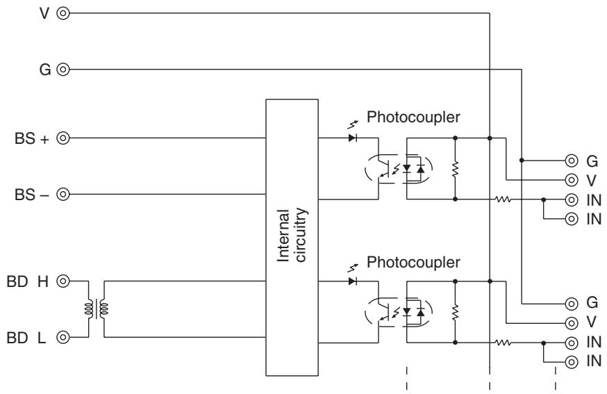
The following diagram shows the internal circuits for the SRT2-VID08S-1.
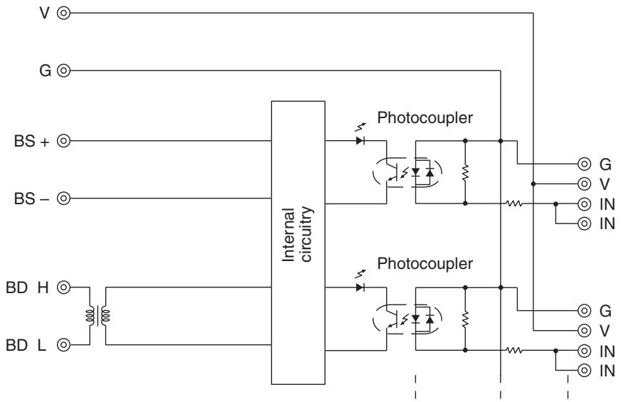
The following diagram shows the internal circuits for the SRT2-VID16ML.
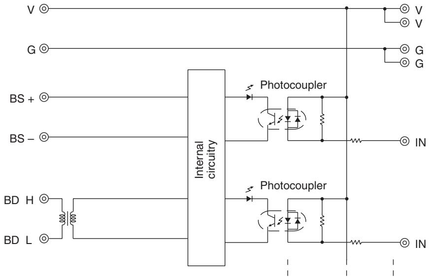
The following diagram shows the internal circuits for the SRT2-VID16ML-1
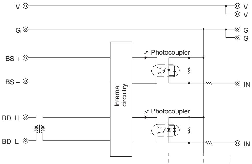
Wiring
- Communications Connector Pin Arrangement
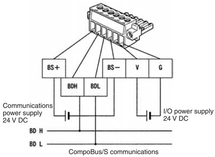
The communications connector (provided as standard) can be ordered as the following product: BL3.5/6F (product no. 160668) manufactured by Weidmuller Co., Ltd.
Note 1. OMRON recommends the following products manufactured by Weidmuller Co., Ltd. for use as crimp terminals.
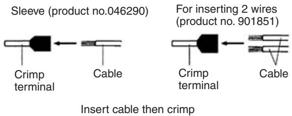
- The following special tool is available:
Crimper PZ1.5 (product no. 900599) manufactured by Weidmuller Co., Ltd.
- Cable Connector Pin Arrangement (SRT2-VID08S and SRT2-VID08S-1)
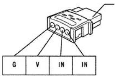
Cable connector (Sold separately)
Cable Connector
| Model | Compatible cable conductor size |
| XS8A-0441 | 0.3 to 0.5 mm² |
| XS8A-0442 | 0.14 to 0.2 mm² |
Note The XS8A-0441 and XS8A-0442 Connectors are not provided with the Unit. The Connectors must be ordered separately.
- MIL Connector Pin Arrangement (SRT2-VID16ML and SRT2-VID16ML-1)
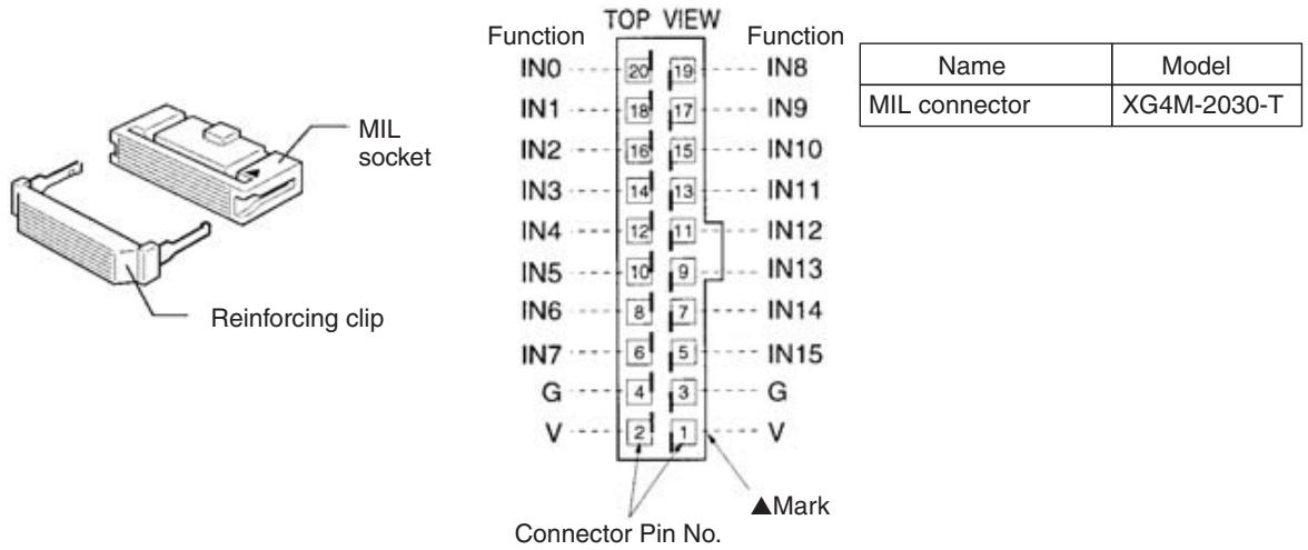
Note The XG4M-2030-T MIL Connector is not provided as standard and must be ordered separately.
- Terminal Arrangement and Wiring Method
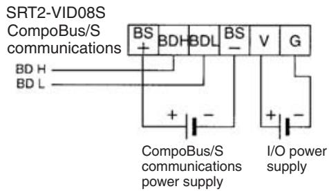
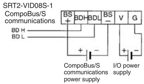
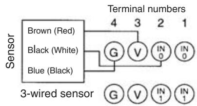
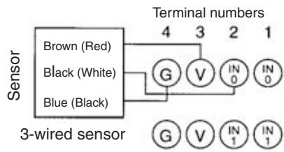
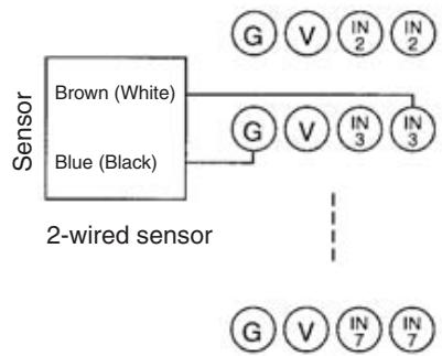
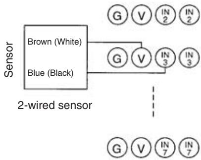
Note 1. The V terminals are all connected internally, as are the G terminals. When providing I/O power from a communications connector, power can be provided to sensors from the V and G terminals of the corresponding cable connector.
- In accordance with the changes in the standards for photoelectric sensors and proximity sensors, wire colors have been changed. Colors in parentheses are the old wire colors.
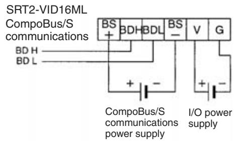
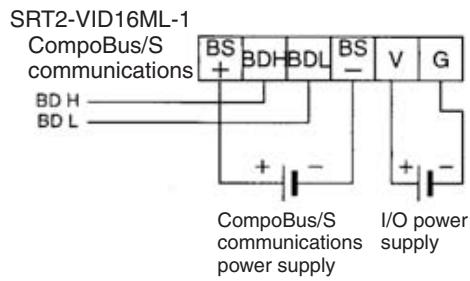
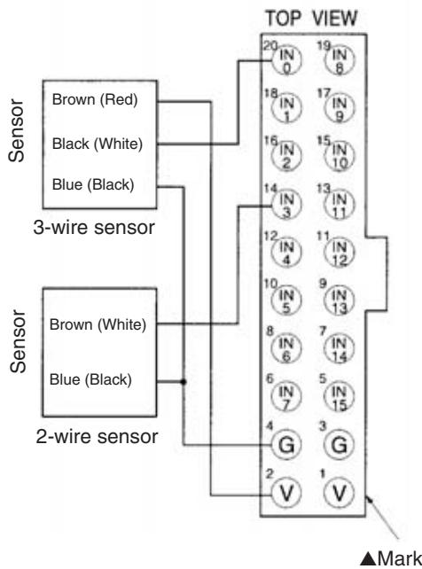
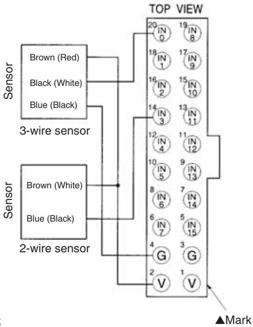
Note
- The V terminals are all connected internally, as are the G terminals. When providing I/O power from a communications connector, power can be provided to sensors from the V and G terminals of the MIL Connector.
- In accordance with the changes in the standards for photoelectric sensors and proximity sensors, wire colors have been changed. Colors in parentheses are the old wire colors.
Compatible External Input Devices and Cables
Models with Sensor Connectors (SRT2-VID08S-1)
The XS8A-0441 and XS8A-0442 Connectors (sold separately) are used to connect to external input devices. Use the following flowchart to check the compatibility of external input devices and cables. Refer to 3-4-3 Cable Connector Wiring and Assembly for details on the assembly, wiring, and installation of cable connectors.

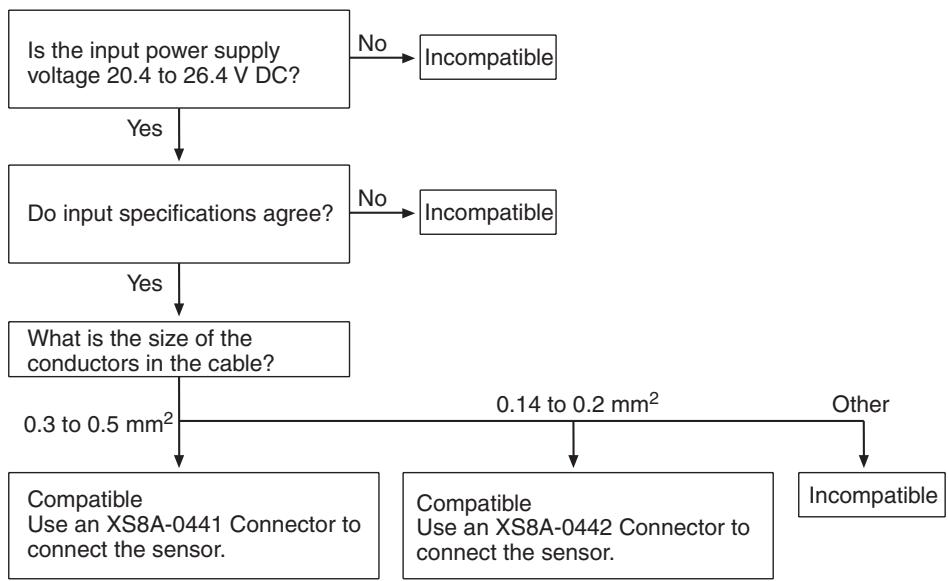
Note 1. The size of the sensor cable conductor is calculated as below. Conductor description of sensor cable:
Outside diameter of cable (number of wires/wire diameter)
conductor size (mm^2)
= (wire~diameter / 2)^2× × number~of~wires
Example: E3S-A Sensor
4(18 / 0.12) Conductor size (mm^2)
= (0.12 / 2)^2 × 3.14 × 18 = 0.20
Since the conductor size works out to be 0.2mm^2 , use XS8A-0442 Connector.
2. The XS8A-0441 and XS8A-0442 Connectors are not provided with the Unit. The Connectors must be ordered separately.
Models with MIL Connectors (SRT2-VID16ML-1)
The MIL Connector can be connected to external devices using either of the following methods.
1,2,3... 1. Using an XG4A-2030-T MIL Connector (sold separately) to Assemble Your Own Cable
For details, refer to MIL Connector Wiring and Assembly on page 258.
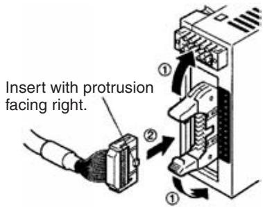
- Connecting with OMRON Products Using an MIL-compatible Cable Manufactured by OMRON
MIL-compatible cable

Cross power supply cable
G79-150C (L = 500mm)
G79-I25C (L = 250mm)
Straight power supply cable
G79-O50C (L = 500mm)
G79-O25C (L = 250mm)
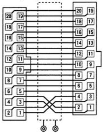
Wiring diagram
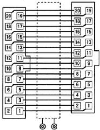
Wiring diagram
Compatible OMRON Products Used with MIL Connectors
| Slave model number | Connecting cable | Compatible product |
| SRT2-VID16ML | G79-150C (50 cm) | G7TC-IA16/ID16 |
| G79-125C (25 cm) | ||
| G79-050C (50 cm) | XW2D-20G6 | |
| G79-025C (25 cm) | XW2B-20G5/20G4 | |
| SRT2-VID16ML-1 | G79-050C (50 cm) | XW2D-20G6 |
| G79-025C (25 cm) | XW2B-20G5/20G4 | |
| SRT2-VOD16ML | G79-050C (50 cm) | G7TC-OC16/08 |
| G79-025C (25 cm) | G70D Series | |
| G70R-SOC08 | ||
| G70A-ZOC16-3 and Relays | ||
| XW2D-20G6 | ||
| XW2B-20G5/20G4 | ||
| SRT2-VOD16ML-1 | G79-I50C (50 cm) | G7TC-OC16-1 |
| G79-I25C (25 cm) | ||
| G79-050C (50 cm) | G70D-SOC16-1/FOM16-1 | |
| G79-025C (25 cm) | G70A-ZOC16-4 and Relays | |
| XW2D-20G6 | ||
| XW2B-20G5/20G4 |
Note MIL-compatible cables are not provided as standard and must be ordered separately.
Dimensions
- Models with Sensor Connectors
All dimensions are in mm.
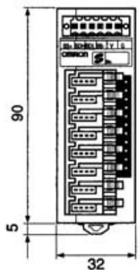
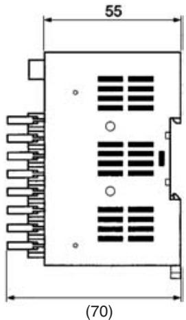
- Models with MIL Connector
All dimensions are in mm.
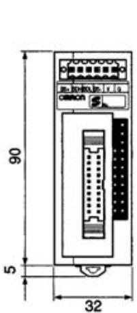
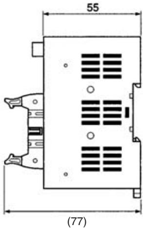
Wiring Dimensions
- Models with Sensor Connector
All dimensions are in mm.
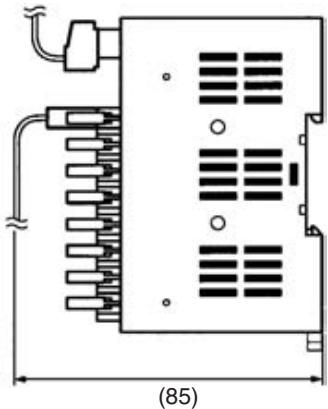
- Models with MIL Connector
All dimensions are in mm.
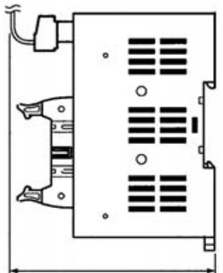
(82)
Mounting Methods
Connector Terminals can be mounted using any of methods 1 to 4 below.
1,2,3... 1. Mounting Directly to DIN Track (Mounting Brackets Not Required)

a) Hook over the top of the DIN Track, then press the Connector Terminal against the DIN Track.
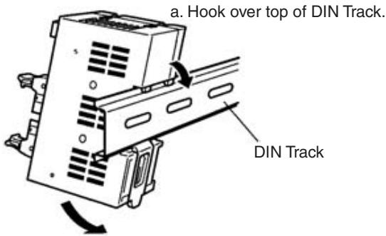
b. The DIN Track Mounting Hook will engage automatically when the Connector Terminal is pressed against the DIN Track.
b) Secure both sides of the Connector Terminal with two end plates.
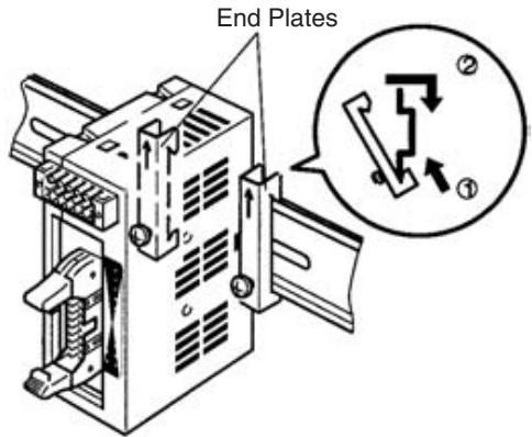
Hook the bottom, then the top of the end plate over the track, and fasten with a screw.
- Mounting on DIN Track with Connector Side Facing Upward (Mounting Brackets A and B Required)
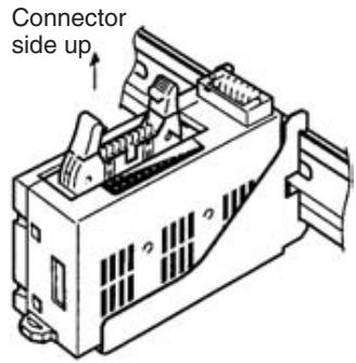
a) Secure Mounting Bracket A on the DIN Track with two Phillips screws.
c. Secure Mounting Bracket A on DIN Track with two Phillips screws. These screws are provided with Mounting Bracket A.
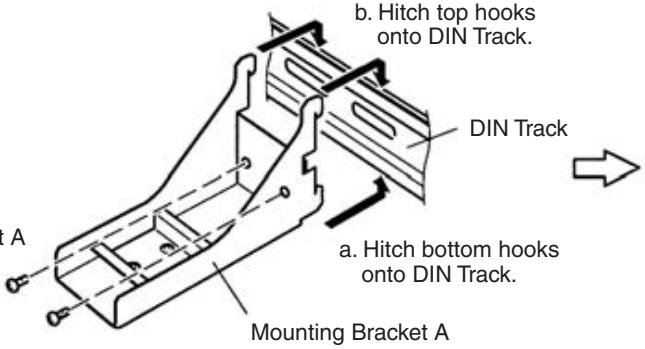
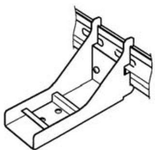
b) Press the Connector Terminal down into Mounting Bracket A.
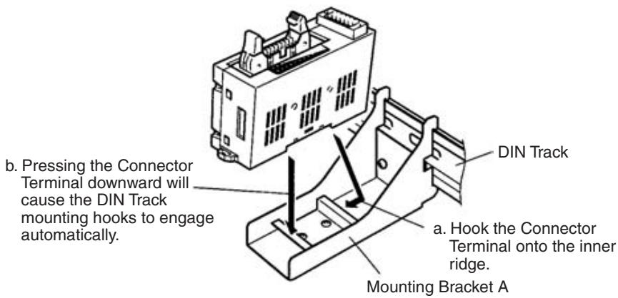
- Mounting Perpendicularly to Wall or Panel (Mounting Bracket B Required)
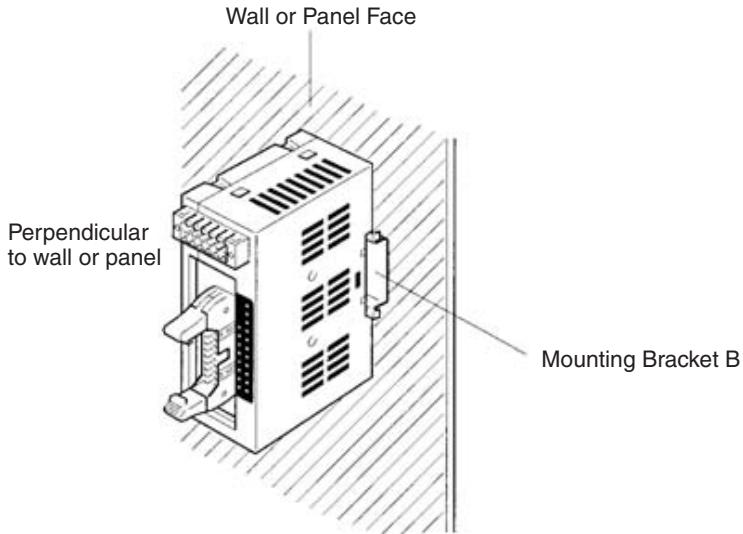
a) Attach Mounting Bracket B to the wall or panel with two Phillips screws.
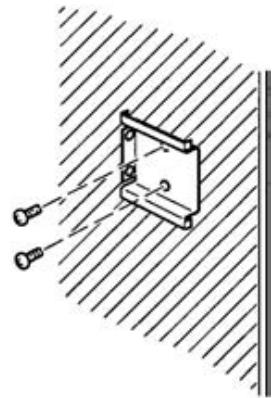
b) Using Mounting Bracket B in place of the DIN Track, attach the Connector Terminal to it as you would to the DIN Track directly.
- Mounting Flat against Wall or Panel (Mounting Bracket B Required)
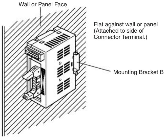
a) Attach Mounting Bracket B perpendicularly to the wall or panel with two Phillips screws.
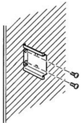
b) Using Mounting Bracket B in place of the DIN Track, attach the Connector Terminal to it as you would to the DIN Track directly.
Mounting Bracket Dimensions
The following diagram shows the dimensions of Mounting Brackets A and B.
Mounting Bracket A (SRT2-ATT01)
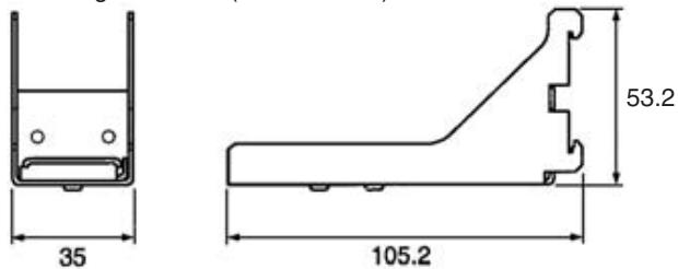
Mounting Bracket B (SRT2-ATT02)
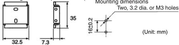
Mounting Methods
All dimensions are in mm.
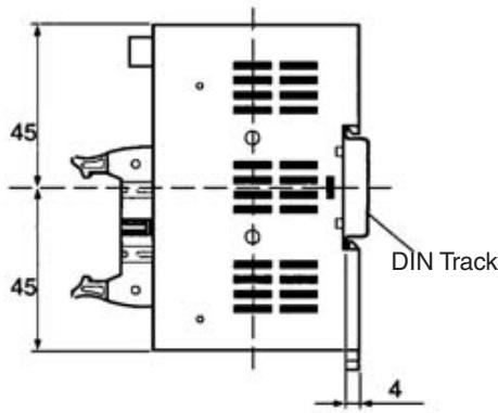
1. Mounting Directly to DIN Track
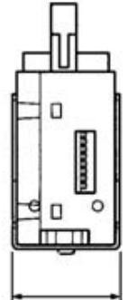
2. Mounting on DIN Track with Connector Side Facing Upward
(35)
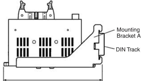
(120)
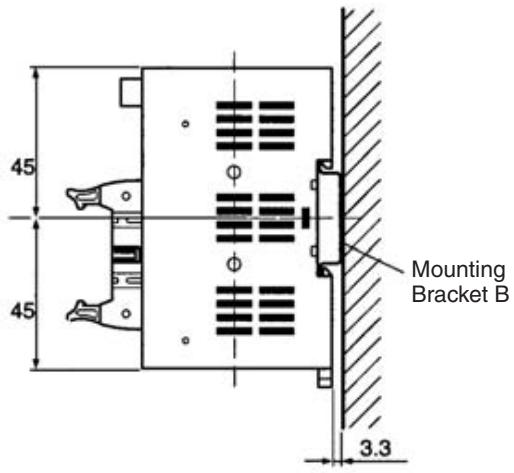
3. Mounting Perpendicular to Wall or Panel
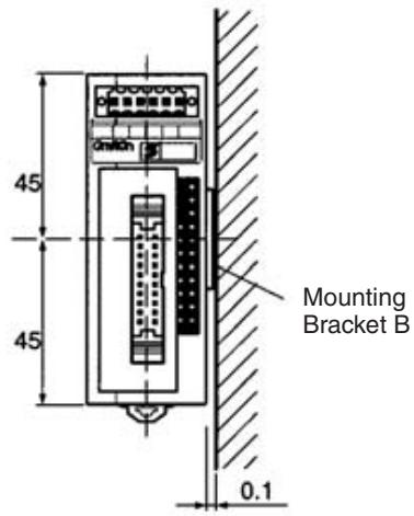
4. Mounting Flat against Wall or Panel
Distance from Duct
(Leave space of at least 20mm above and below the Connector Terminal.)
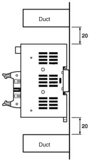
5-2-2 SRT2-VOD□□□ (-1) Connector Terminals with 8 or 16 Transistor Outputs
Specifications
The following tables show the ratings and output specifications for the SRT2-VOD□□□(-1).
Ratings
| Item | Specification | |
| Models | SRT2-VOD08S SRT2-VOD08S-1 SRT2-VOD16ML SRT2-VOD16ML-1 | |
| Output points/Connection type | SRT2-VOD08S: 8 points (NPN)/Cable connector output SRT2-VOD08S-1: 8 points (PNP)/Cable connector output SRT2-VOD16ML: 16 points (NPN)/MIL connector output SRT2-VOD16ML-1: 16 points (PNP)/MIL connector output | |
| Connection | Output | SRT2-VOD08S (-1): By XS8A-0441 or XS8A-0442 Connector (both sold separately) SRT2-VID16ML (-1): By XG4M-2030-T MIL Connector (sold separately), or G79-050C, G79-025C, G79-150C and G79-125C MIL-compatible Cables (all sold separately) |
| Communications power | By communications connector (included as standard) | |
| I/O power | ||
| Power supply type | Multiple power supplies | |
| Communications power supply voltage | 14 to 26.4 V DC (Power can be supplied from the communications cable) | |
| I/O power supply voltage | 20.4 to 26.4 V DC (24 V DC +10%/_-15%) | |
| I/O power supply current | Cable connector: 2.4 A max. MIL connector: 2.0 A max. | |
| Current consumption (See note.) | Communications power: 50 mA max. at 24 V DC | |
| Noise immunity | ±1.5 kVp-p with a pulse width of 0.1 to 1 μs and a rise time of 1 ns (tested with impulse noise simulator) | |
| Vibration resistance | 10 to 150 Hz, 1.0-mm double amplitude or 70 m/s² | |
| Shock resistance | 200 m/s² | |
| Dielectric strength | 500 V AC (between insulated circuits) | |
| Ambient temperature | Operating: -10 to 55°C (with no icing or condensation) Storage: -25 to 65°C (with no icing or condensation) | |
| Ambient humidity | Operating: 25% to 85% (with no condensation) Storage: 25% to 85% (with no condensation) | |
| Operating environment | No corrosive gases | |
| Standard accessory | 1 communications connector Note: Mounting Brackets A (SRT2-ATT01) and B (SRT2-ATT02) are sold separately. | |
| Mounting strength | Pulling: 100 N in each direction. (When mounted with Mounting Bracket B: 40 N) | |
| Item | Specification | |
| Terminal strength | Pulling: As stated below Communications connector: 100 N Cable connector: 40 N MIL Connector: 100 N Tightening: 0.25 N • m (for communications connector) | |
| Node number settings | The node number is set on a DIP switch. (Set the node number before turning ON the Slave.) | |
| Weight | Approx. 75 g | |
Note This is the current consumption when all the maximum simultaneous output points are ON, excluding the current consumption of external sensors.
Output Specifications
| Item | VOD08S/VOD08S-1 | VOD16ML/VOD16ML-1 |
| Output current | 0.3 A max./point | 0.3 A max./point (2 A com-mon) (See note.) |
| Residual voltage | VOD08S/VOD16ML: 1.2 V DC max. (between each input terminal and G)VOD08S-1/VOD16ML-1: 1.2 V DC max. (between each input terminal and V) | |
| Leakage current | VOD08S/VOD16ML: 0.1 mA max.VOD08S-1/VOD16ML-1: 0.1 mA max. | |
| ON delay time | 0.5 ms max. | |
| OFF delay time | 1.5 ms max. | |
| Insulation method | Photocoupler | |
| Number of circuits | 8 points/single common circuit | 16 points/single common cir-cuit |
Note When using the V and G terminals of the MIL connector, make sure that current does not exceed 1 A at each terminal.
Slave Components
The following diagram shows the main components of the SRT2-VOD□□□(-□)Connector Terminals with Transistor Outputs. The functions of these components are described below.
Models with Sensor Connectors SRT2-VOD08S/VOD08S-1
Communications connector
Used to connect CompoBus/S communications data (BD H, BD L), communications power supply, and I/O power supply (see page 256).
One compatible connector is provided as standard.
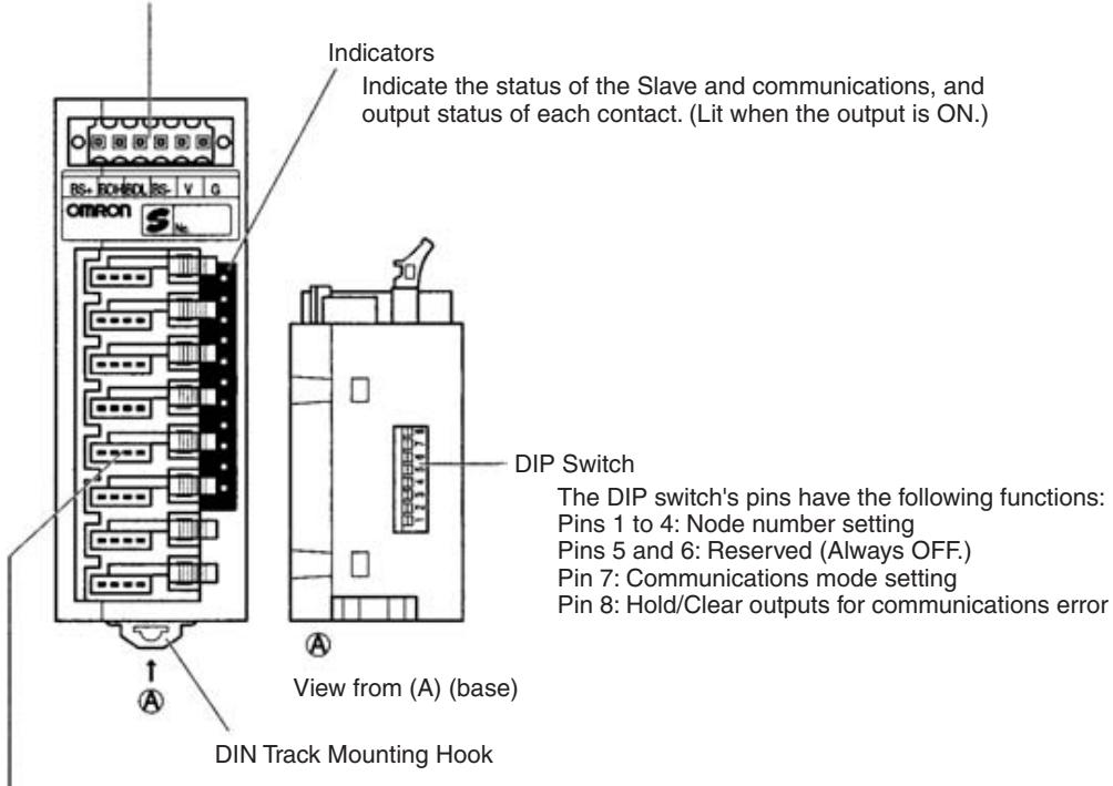
Output connector (cable connector)
Connect 8 outputs with cable connector (see page 67).
The XS8A-0441 Cable Connector (compatible conductor size: 0.3 to 0.5mm^2 ) and XS8A-0442 Cable
Connector (compatible conductor size: 0.14 to 0.2mm^2 ) are sold separately.
Models with MIL Connectors
SRT2-VOD16ML/VOD16ML-1
Communications connector
Used to connect CompoBus/S communications data (BD H, BD L), communications power supply, and I/O power supply (see page 256).
One compatible connector is provided as standard.
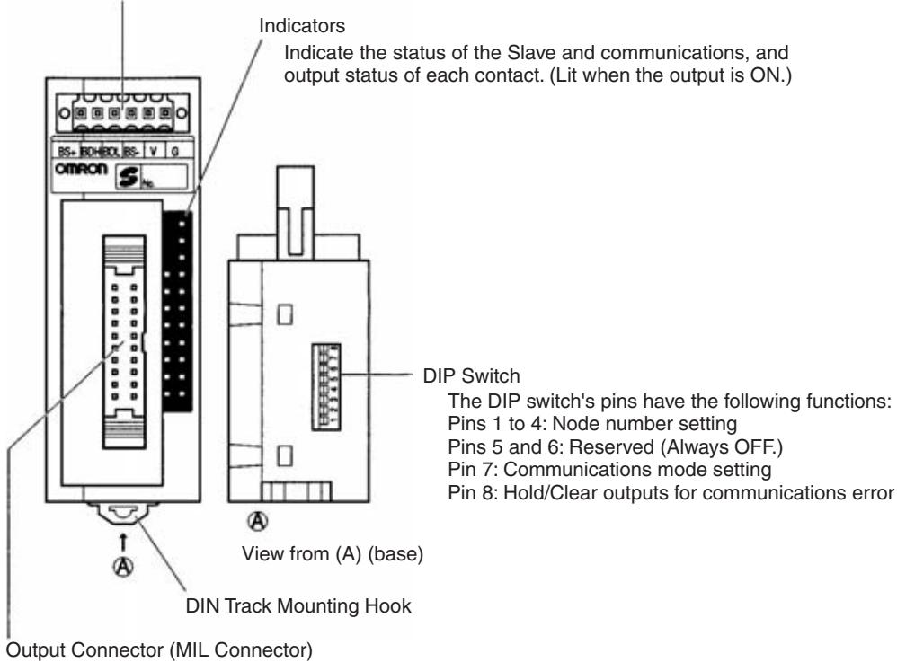
Connect 16 outputs with MIL connector (see page 258).
XG4M-2030-T MIL Connector and compatible cable are sold separately.
Indicators
The following table shows the meaning of the indicators.
| Indicator | Status | Meaning |
| PWR (green) | ON | The communications power supply is ON. |
| OFF | The communications power supply is OFF. | |
| COMM (yellow) | ON | Normal communications |
| OFF | A communications error has occurred or the Unit is in standby status. | |
| ERR (red) | ON | A communications error has occurred. |
| OFF | Normal communications or the Unit is in standby status. | |
| 0 to 7 (8 outputs) | ON | The corresponding output is ON. |
| 0 to 15 (16 outputs) | OFF | The corresponding output is OFF or the Unit is in standby status. |
DIP Switch
The DIP switch is located on the base of the Connector Terminal.
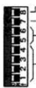
Hold/Clear outputs for communications error
Communications mode setting
Reserved (Always OFF.)
Node number setting
Note Always turn OFF the Slave before changing DIP switch settings.
Node Number Settings
Set the node number with pins 1 through 4, as shown in the following table.
| Node number | Pin 4 (8) | Pin 3 (4) | Pin 2 (2) | Pin 1 (1) |
| 0 | OFF | OFF | OFF | OFF |
| 1 | OFF | OFF | OFF | ON |
| 2 | OFF | OFF | ON | OFF |
| 3 | OFF | OFF | ON | ON |
| 4 | OFF | ON | OFF | OFF |
| 5 | OFF | ON | OFF | ON |
| 6 | OFF | ON | ON | OFF |
| 7 | OFF | ON | ON | ON |
| 8 | ON | OFF | OFF | OFF |
| 9 | ON | OFF | OFF | ON |
| 10 | ON | OFF | ON | OFF |
| 11 | ON | OFF | ON | ON |
| 12 | ON | ON | OFF | OFF |
| 13 | ON | ON | OFF | ON |
| 14 | ON | ON | ON | OFF |
| 15 | ON | ON | ON | ON |
Communications Mode Settings
The following communications modes are set with pin 7.
| Pin 7 | Communications mode | Communications distance | Communications baud rate | Communications cycle time |
| OFF | High-speed Communications Mode | 100 m max. | 750 kbps | 0.5 or 0.8 ms |
| ON | Long-distance Communications Mode | 500 m max. | 93.75 kbps | 4.0 or 6.0 ms |
Note Make sure that the communications mode of the Slave is the same as that of the Master Unit. If the communications modes are not the same, normal communications with the Master Unit will not be possible. The operating status of the Slave can be verified with LED indicators. Refer to 6-5-1 Indicators.
Hold/Clear Outputs for Communications Error
Pin 8 is used to set the output data status when a communications error occurs, as shown in the following table.
| Pin 8 (HOLD) | Setting |
| OFF | Clear output status |
| ON | Maintain output status |
Internal Circuits
The following diagram shows the internal circuits for the SRT2-VOD08S.
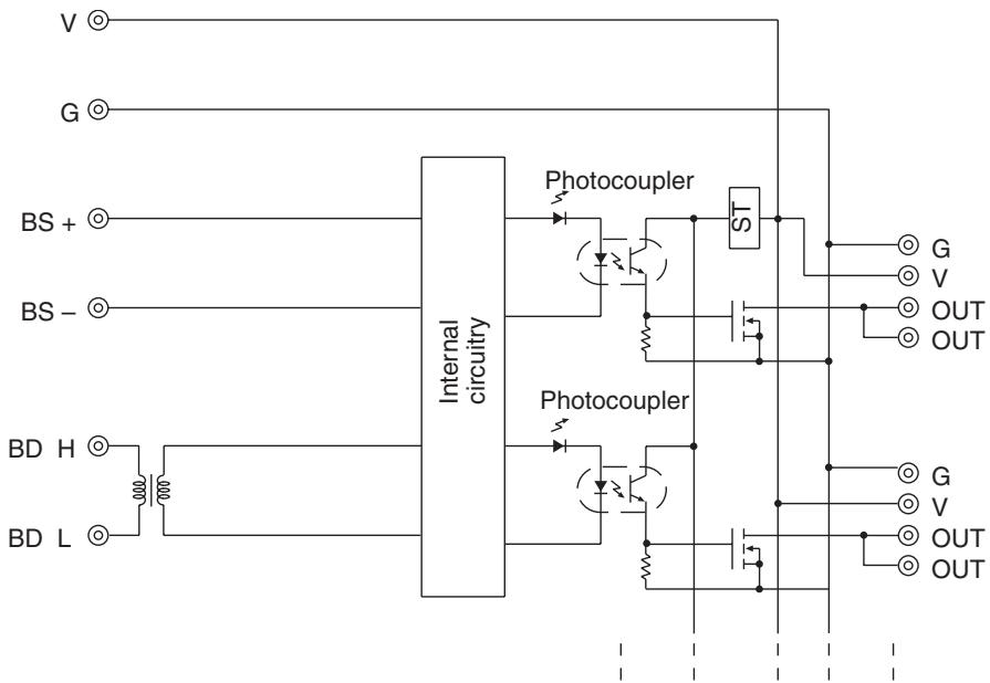
ST: Step-down transformer
The following diagram shows the internal circuits for the SRT2-VOD08S-1.
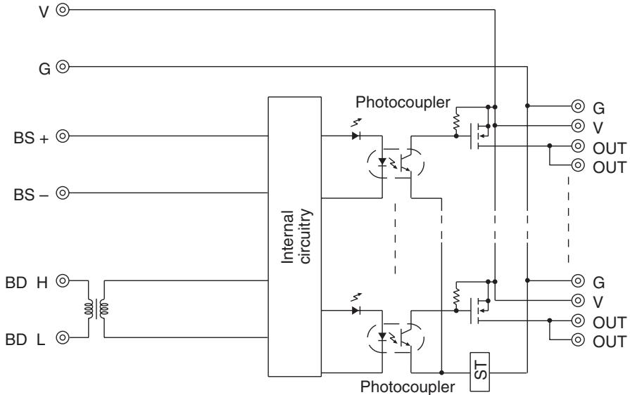
ST: Step-down transformer
The following diagram shows the internal circuits for the SRT2-VOD16ML.
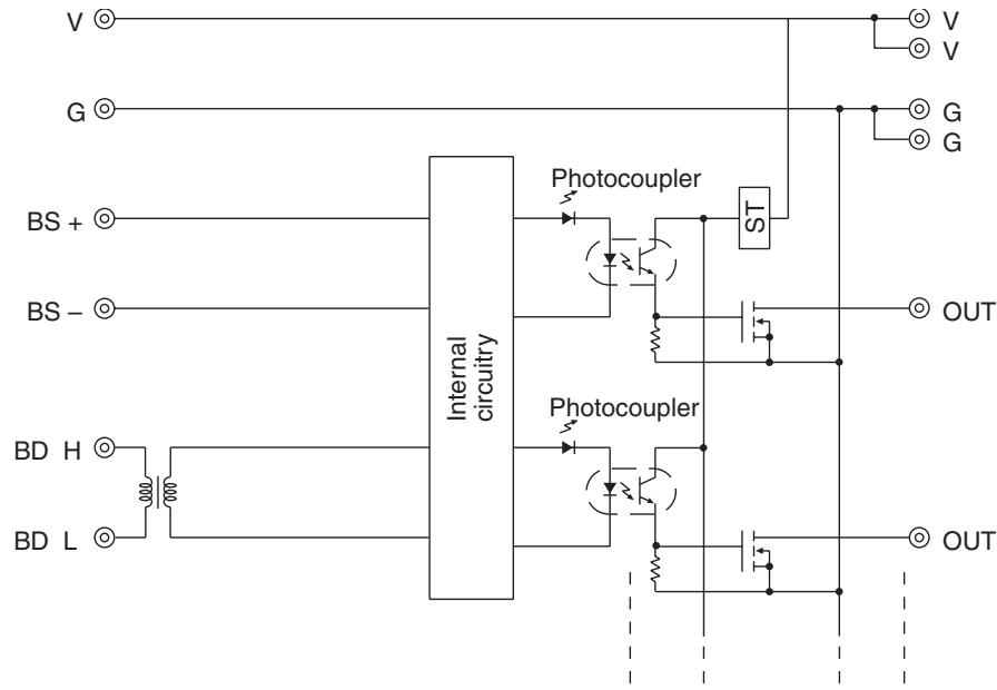
ST: Step-down transformer
The following diagram shows the internal circuits for the SRT2-VOD16ML-1.
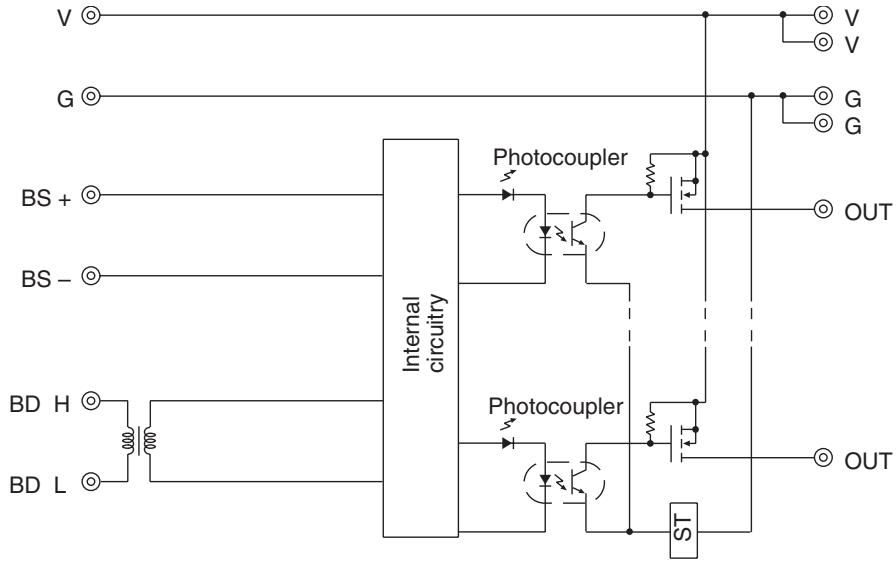
ST: Step-down transformer
Wiring
- Communications Connector Pin Arrangement
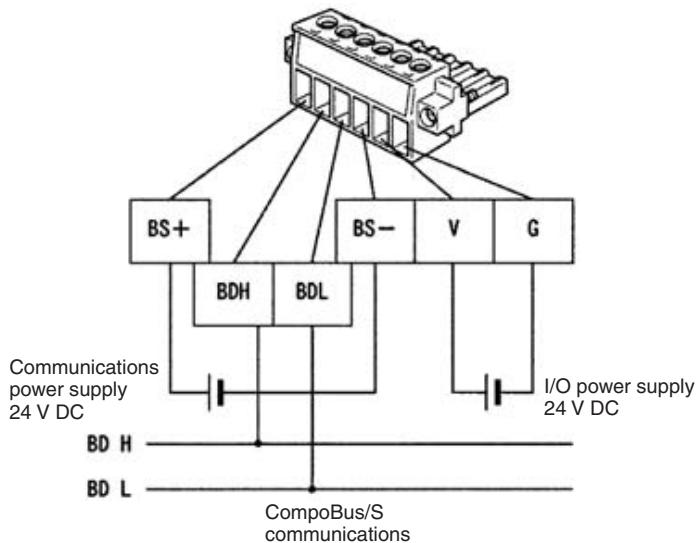
The communications connector (provided as standard) can be ordered as the following product:
BL3.5/6F (product no. 160668) manufactured by Weidmuller Co., Ltd.
Note 1. OMRON recommends the following products manufactured by Weidmuller Co., Ltd. for use as crimp terminals.
Sleeve (product no.046290)
For inserting 2 wires (product no. 901851)
Crimp Terminal
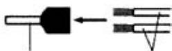
Crimp Terminal
Cable
Insert cable then crimp
- The following special tool is available:
Crimper PZ1.5 (product no. 900599) manufactured by Weidmuller Co., Ltd.
- Cable Connector Pin Arrangement
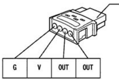
Cable connector (sold separately)
Cable connector
| Model | Compatible cable conductor size |
| XS8A-0441 | 0.3 to 0.5 mm² |
| XS8A-0442 | 0.14 to 0.2 mm² |
Note The XS8A-0441 and XS8A-0442 Connectors are not provided with the Unit. The Connectors must be ordered separately.
- MIL Connector Pin Arrangement (SRT2-VOD16ML and SRT2-VOD16ML-1)
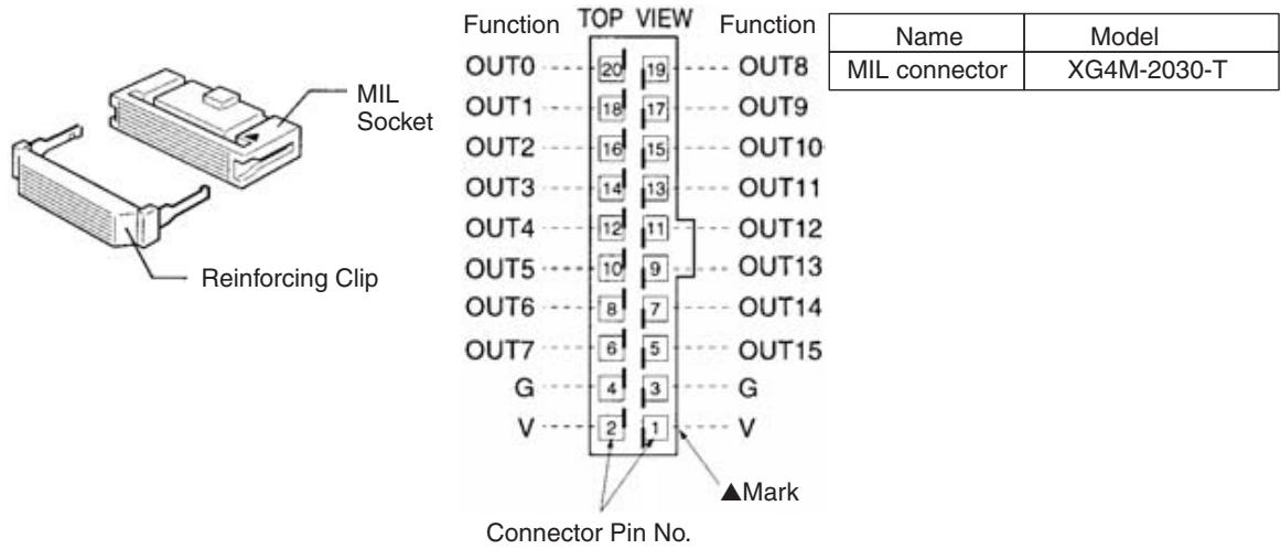
Note The XG4M-2030-T MIL Connector is not provided as standard and must be ordered separately.
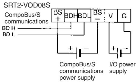
- Terminal Arrangement and Wiring Method
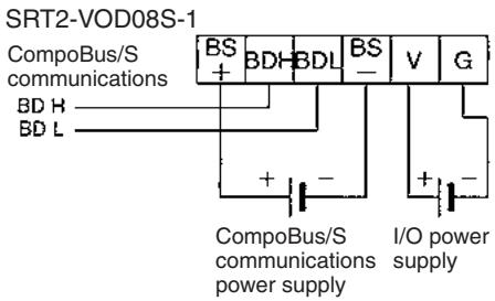
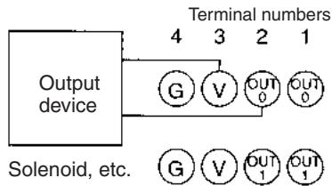
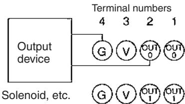
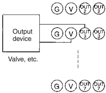
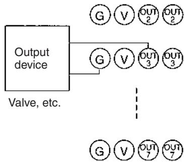
Note 1. The V terminals are all connected internally, as are the G terminals. When providing I/O power from a communications connector, power can be provided to output devices from the V and G terminals of the corresponding cable connector.
- When inductive loads such as solenoids and valves are used, either use loads with built-in diodes that absorb the back-electromotive force or connect a diode externally.
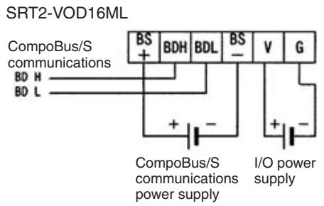
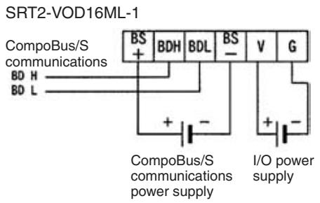
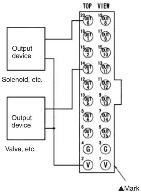
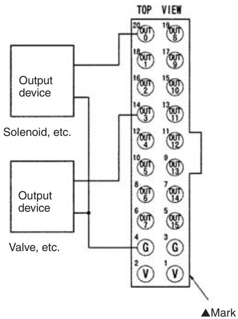
Note
- The V terminals are all connected internally, as are the G terminals. When providing I/O power from a communications connector, power can be provided to output devices from the V and G terminals of the MIL Connector.
- When inductive loads such as solenoids and valves are used, either use loads with built-in diodes that absorb the back-electromotive force or connect a diode externally.
Compatible External Output Devices and Cables
Models with Sensor Connectors (SRT2-VOD08S-1)
The XS8A-0441 and XS8A-0442 Connectors (sold separately) are used to connect to external output devices. Use the following flowchart to check the compatibility of external output devices and cables. Refer to 3-4-3 Cable Connector Wiring and Assembly for details on the assembly, wiring, and installation of cable connectors.
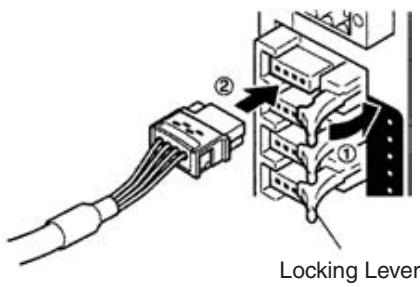
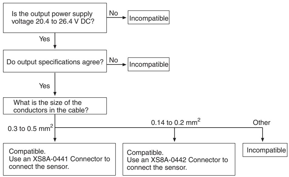
Note The XS8A-0441 and XS8A-0442 Connectors are not provided with the Unit. The Connectors must be ordered separately.
Models with MIL Connector (SRT2-VOD16ML-1)
The MIL Connector can be connected to external devices in either of the following methods.
1,2,3... 1. Using an XG4A-2030-T MIL Connector (sold separately) to Assemble Your Own Cable
For details, refer to MIL Connector Wiring and Assembly on page 258.

- Connecting with OMRON Products Using an MIL-compatible Cable Manufactured by OMRON
MIL-compatible cable

Straight power supply cable
G79-O50C (L = 500 mm)
G79-O25C (L = 250mm)
Cross power supply cable
G79-150C (L = 500mm)
G79-I25C (L = 250mm)
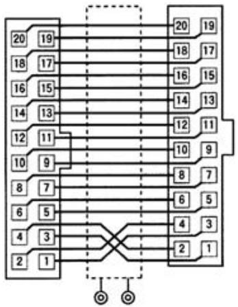
Wiring diagram
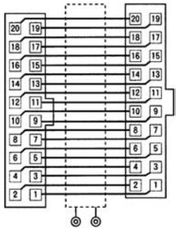
Wiring diagram
Compatible OMRON Products Used with MIL Connectors
| Slave model number | Connecting cable | Compatible product |
| SRT2-VID16ML | G79-150C (50 cm) | G7TC-IA16/ID16 |
| G79-125C (25 cm) | ||
| G79-050C (50 cm) | XW2D-20G6 | |
| G79-025C (25 cm) | XW2B-20G5/20G4 | |
| SRT2-VID16ML-1 | G79-050C (50 cm) | XW2D-20G6 |
| G79-025C (25 cm) | XW2B-20G5/20G4 | |
| SRT2-VOD16ML | G79-050C (50 cm) | G7TC-OC16/08 |
| G79-025C (25 cm) | G70D Series | |
| G70R-SOC08 | ||
| G70A-ZOC16-3 and Relays | ||
| XW2D-20G6 | ||
| XW2B-20G5/20G4 | ||
| SRT2-VOD16ML-1 | G79-I50C (50 cm) | G7TC-OC16-1 |
| G79-I25C (25 cm) | ||
| G79-050C (50 cm) | G70D-SOC16-1/FOM16-1 | |
| G79-025C (25 cm) | G70A-ZOC16-4 and Relays | |
| XW2D-20G6 | ||
| XW2B-20G5/20G4 |
Note MIL-compatible cables are not provided as standard and must be ordered separately.
Dimensions
- Models with Sensor Connectors
All dimensions are in mm.
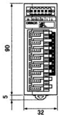
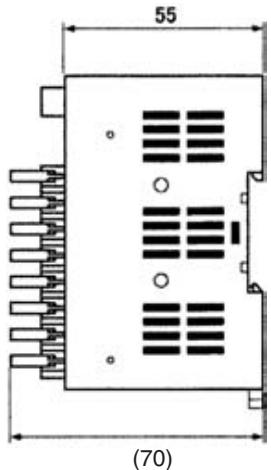
- Models with MIL Connectors
All dimensions are in mm.
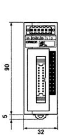
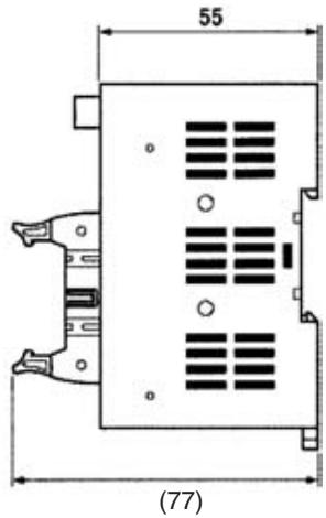
Note For details on wiring dimensions, installation methods, Mounting Bracket dimensions, and mounting methods, refer to 5-2-1 SRT2-VID□□□(-1) Connector Terminals with 8 Input or 16 Output Transistors.
5-2-3 SRT2-ID32ML (-1) Connector Terminals with 32 Transistor Inputs
Specifications
The following tables show the ratings and input specifications for the SRT2-ID32ML (-1).
Ratings
| Item | Specification |
| Models | SRT2-ID32ML, SRT2-ID32ML-1 |
| Input points/Connection type | SRT2-ID32ML: 32 points (NPN)/MIL connector input SRT2-ID32ML-1: 32 points (PNP)/MIL connector input |
| Connection | Communications power: By communications connector (included as standard) Input: MIL connector or MIL-compatible Cables (both sold separately) (see page 233) I/O power: MIL connector |
| Power supply type | Multiple power supplies |
| Communications power supply voltage | 14 to 26.4 V DC (Power can be supplied from the communications cable) |
| I/O power supply voltage | 20.4 to 26.4 V DC (24 V DC +10%/_-15%) |
| Current consumption (See note.) | Communications power: 50 mA max. at 24 V DC |
| Noise immunity | 1.5 kVp-p with a pulse width of 0.1 to 1 μs and a rise time of 1 ns (tested with impulse noise simulator) |
| Vibration resistance | 10 to 150 Hz, 0.7-mm double amplitude or 50 m/s² |
| Shock resistance | 150 m/s² |
| Dielectric strength | 500 V AC (between insulated circuits) |
| Ambient temperature | Operating: -10 to 55°C (with no icing or condensation) Storage: -25 to 65°C (with no icing or condensation) |
| Ambient humidity | Operating: 25% to 85% (with no condensation) Storage: 25% to 85% (with no condensation) |
| Operating environment | No corrosive gases |
| Standard accessory | 1 communications connector Note Mounting Bracket B (SRT2-ATT02) is sold separately |
| Mounting strength | 50 N |
| Terminal strength | Pulling: As stated below Communications connector: 30 N MIL connector: 30 N |
| Tightening torque | Communications connector: 0.25 to 0.3 N·m |
| Node number settings | The node number is set on a DIP switch. (Set the node number before turning ON the Slave.) |
| Weight | Approx. 100 g max. |
Note This is the current consumption when all the maximum simultaneous input points are ON, excluding the current consumption of external sensors.
Input Specifications
| Item | Specification |
| Input current | 6 mA max./point at 24 V DC 3 mA min./point at 17 V DC |
| ON delay time | 1.5 ms max. |
| OFF delay time | 1.5 ms max. |
| ON voltage | ID32MIL: 17 V DC min. (between each input terminal and V) ID32ML-1: 17 V DC (between each input terminal and G) |
| OFF voltage | ID32ML: 5 V DC max. (between each input terminal and V) ID32M-1: 5 V DC max. (between each input terminal and G) |
| OFF current | 1 mA max. |
| Insulation method | Photocoupler |
| Max. simultaneous input points | 32 points |
| Number of circuits | 32 points/single common circuit |
Simultaneous Input Points and Installation Spacing
For Connector Terminals with 32 transistor inputs, the ambient operating temperature places a limit on the maximum number of points that can be turned ON simultaneously.
For example, if Connector Terminals are mounted in a direction other than the following directions at an ambient operating temperature of 55^ with all the 32 input points turned ON simultaneously, the Connector Terminals must not be mounted closely together.
a. Input Units mounted upside down
b. Input Units mounted horizontally with the MIL connectors facing downward
c. Input Units mounted facing downward
If 32 input points of any Unit mounted in the above directions need to be turned ON simultaneously, the spacing between the Units is limited as shown in the following graph. For example, if the ambient operating temperature is 55^ , a minimum space of 10mm is required between Units.
a. Input Units mounted upside down
b. Input Units mounted horizontally with the MIL connectors facing downward
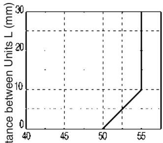
Operating ambient temperature (^)
c. Input Units mounted facing downward
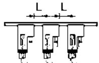
Slave Components
The following diagram shows the main components of the SRT2-ID32ML (-□) Connector Terminals with Transistor Inputs. The functions of these components are described below.
Communications Connector
Used to connect CompoBus/S communications data (BD H, BD L) and communications
power supply (see page 256). One compatible connector is provided as standard.

Indicators
The following table shows the meaning of the indicators.
| Indicator | Name | Status | Meaning |
| PWR (green) | Power | ON | The communications power sup- ply is ON. |
| OFF | The communications power sup- ply is OFF. | ||
| COMM1 (yellow) | Communica- tions | ON | Normal communications on word m. |
| OFF | A communications error has occurred on word m or the Unit is in standby status. | ||
| COMM2 (yellow) | ON | Normal communications on word m+1. | |
| OFF | A communications error has occurred on word m+1 or the Unit is in standby status. | ||
| ERR1 (red) | Communica- tions error | ON | A communications error has occurred on word m. |
| OFF | Normal communications on word m or the Unit is in standby status. | ||
| ERR2 (red) | ON | A communications error has occurred on word m+1. | |
| OFF | Normal communications on word m+1 or the Unit is in standby sta- tus. | ||
| I (yellow) 0 to 15 (16 inputs) | Input | ON | The corresponding input on word m is ON. |
| OFF | The corresponding input is OFF or the Unit is in standby status. | ||
| II (yellow) 0 to 15 (16 inputs) | ON | The corresponding input on word m+1 is ON. | |
| OFF | The corresponding input on word m+1 is OFF or the Unit is in standby status. |
Switch Settings
Note Word m is the first word allocated in the Unit.
The rotary switch and the DIP switch are located on the upper part of the Connector Terminal.
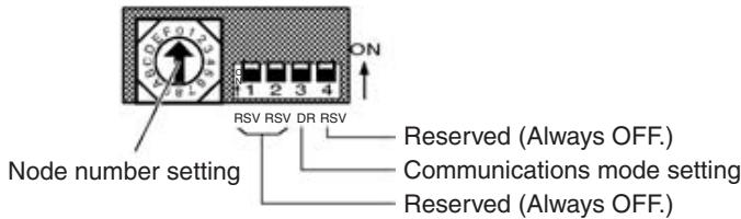
Note Always turn OFF the Slave before changing switch settings.
Node Number Settings
Set the node number in hexadecimal with the rotary switch as shown in the following table.
| Node number | Setting (Hex) | Node number | Setting (Hex) |
| 0 | 0 | 8 | 8 |
| 1 | 1 | 9 | 9 |
| 2 | 2 | 10 | A |
| 3 | 3 | 11 | B |
| 4 | 4 | 12 | C |
| 5 | 5 | 13 | D |
| 6 | 6 | 14 | E |
| 7 | 7 | 15 | F |
Note
- The node number of the 32-point Slave must be set to an even number. If an odd number is input, the odd number less one will be set in the Slave.
- The possible range of node numbers varies with the type of Master and settings in the Master. Refer to 2-1 Communications Specifications for details.
Communications Mode Settings
The following communications modes are set with pin 3 of the DIP switch.
| Pin 3 | Communications mode | Communications distance | Communications baud rate | Communications cycle time |
| OFF | High-speed Communications Mode | 100 m max. | 750 kbps | 0.5 or 0.8 ms |
| ON | Long-distance Communications Mode | 500 m max. | 93.75 kbps | 4.0 or 6.0 ms |
Note Make sure that the communications mode of the Slave is the same as that of the Master Unit. If the communications modes are not the same, normal communications with the Master Unit will not be possible. The operating status of the Slave can be verified with LED indicators. Refer to 6-5-1 Indicators.
Internal Circuits
SRT2-ID32ML
The following diagram shows the internal circuits for the SRT2-ID32ML.
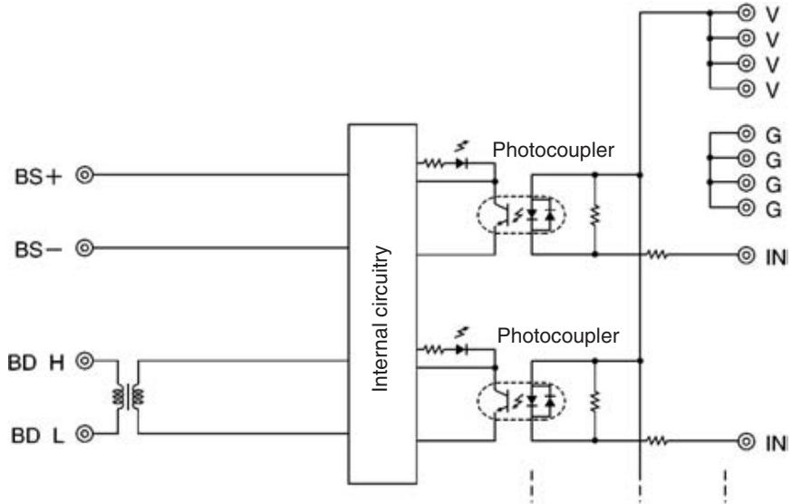
SRT2-ID32ML-1
The following diagram shows the internal circuits for the SRT2-ID32ML-1.
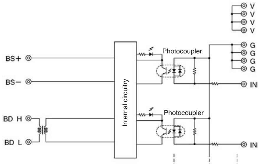
Wiring
Communications Connector Pin Arrangement
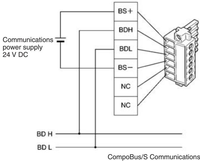
The communications connector (provided as standard) can be ordered as the following product:
BL3.5/6F (product no. 160668) manufactured by Weidmuller Co., Ltd.
Note 1. OMRON recommends the following products manufactured by Weidmuller Co., Ltd. for use as crimp terminals.
Sleeve (product no. 046290)
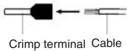
For inserting 2 wires (product no. 901851)

Insert cable then crimp
- The following special tool is available:
Crimper PZ1.5 (product no. 900599) manufactured by Weidmuller Co., Ltd.
MIL Connector Pin Arrangement
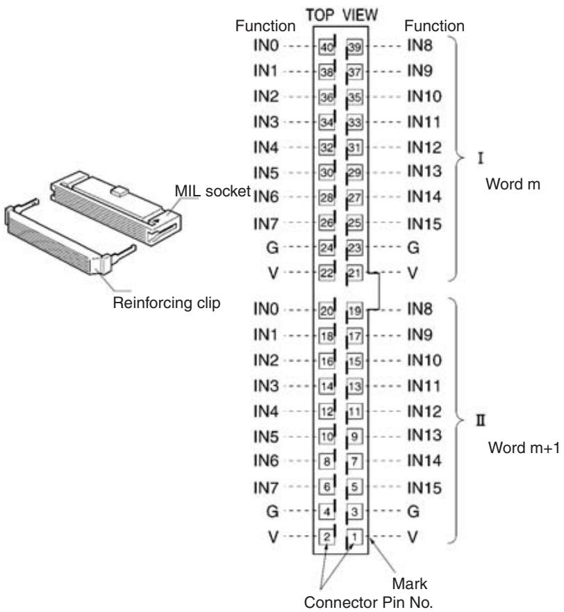
| Name | Model |
| MIL connector | XG4M-4030-T |
Note The XG4M-2030-T MIL Connector is not provided as standard and must be ordered separately.
Terminal Arrangement and Wiring Method
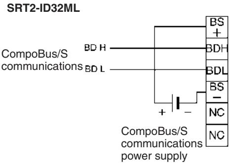
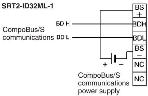
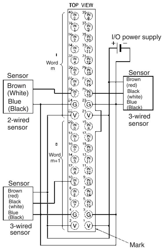
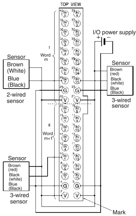
Note 1. The V terminals are all connected internally, as are the G terminals.
2. Wire colors have been changed. Colors in parentheses are the old wire colors.
I/O Allocations
Provided that the first word of the Connector Terminal with 32 transistor inputs allocated to the Master Unit is m, the pin numbers of the MIL connector correspond to the following word and bit allocations.
| Word m | 15 | 14 | 13 | 12 | 11 | 10 | 9 | 8 | 7 | 6 | 5 | 4 | 3 | 2 | 1 | 0 |
| 25 | 27 | 29 | 31 | 33 | 35 | 37 | 39 | 26 | 28 | 30 | 32 | 34 | 36 | 38 | 40 | |
| Word m+1 | 5 | 7 | 9 | 11 | 13 | 15 | 17 | 19 | 6 | 8 | 10 | 12 | 14 | 16 | 18 | 20 |
Compatible External Input Devices and Cables
Connector Terminals with 32 inputs connect to external devices over one of the following method.
1,2,3...
- Using an XG4A-4030-T MIL Connector (sold separately) to Assemble Your Own Cable
For details, refer to MIL Connector Wiring and Assembly on page 258.
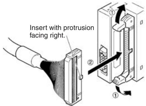
- Connecting with OMRON Products Using MIL-compatible Cables Manufactured by OMRON
Select the MIL-compatible Cable from the following table according to the Connector Terminal and I/O Block to be connected.
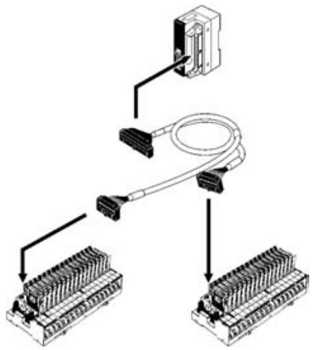
| Slave model | MIL-compatible Cable | Connecting I/O block |
| SRT2-ID32ML | G79-I50-25-D1 (50 cm) | G7TC-ID16 |
| G79-I75-50-D1 (75 cm) | G7TC-IA16 | |
| SRT2-ID32ML-1 | G79-I50-25-D2 (50 cm) | G70A-ZIM16-5 |
| G79-I75-50-D2 (75 cm) |
Note MIL-compatible cables are not provided as standard and must be ordered separately.
The following cables are available, each of which is provided with a single MIL connector for the Connector Terminal end.
| MIL-compatible cable | Remarks |
| G79-A200C-D1 (2 m) | Wire dia.: AWG28 (other end) |
| G79-A500C-D1 (5 m) | All wires are precut. |
| G79-Y100C-D1 (1 m) | Fork terminals provided to other end. |
| G79-Y200-D1 (2 m) | Fork terminal: Nippon Tanshi's 161071-M2 |
| G79-Y500C-D1 (5 m) |
The pin numbers of the MIL connector corresponds to the following color wires marked with color dots.
| Pin | Wire color | Dots | Dot color | Pin | Wire color | Dots | Dot color |
| 1 | Light brown | ■ | Black | 21 | Light brown | ■■■ | Black |
| 2 | Red | 22 | Red | ||||
| 3 | Yellow | Black | 23 | Yellow | Black | ||
| 4 | Red | 24 | Red | ||||
| 5 | Light green | Black | 25 | Light green | Black | ||
| 6 | Red | 26 | Red | ||||
| 7 | Gray | Black | 27 | Gray | Black | ||
| 8 | Red | 28 | Red | ||||
| 9 | White | Black | 29 | White | Black | ||
| 10 | Red | 30 | Red | ||||
| 11 | Light brown | ■■ | Black | 31 | Light brown | ■■■■ | Black |
| 12 | Red | 32 | Red | ||||
| 13 | Yellow | Black | 33 | Yellow | Black | ||
| 14 | Red | 34 | Red | ||||
| 15 | Light green | Black | 35 | Light green | Black | ||
| 16 | Red | 36 | Red | ||||
| 17 | Gray | Black | 37 | Gray | Black | ||
| 18 | Red | 38 | Red | ||||
| 19 | White | Black | 39 | White | Black | ||
| 20 | Red | 40 | Red |
Dimensions
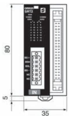
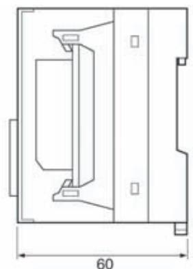
(Unit: mm)
Wired Dimensions
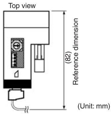
Mounting Methods
The following mounting methods can be used. These methods are the same as those used for mounting Connector Terminals with 8 or 16 inputs.
- DIN track mounting (with no mounting brackets): Refer to page 208.
- Vertical panel mounting (with Mounting Bracket B only): Refer to page 210.
- Horizontal panel mounting (with Mounting Bracket B only): Refer to page 210.
Note The 32-point Connector Terminals cannot be directly panel-mounted with screws. Use the SRT2-ATT02 Mounting Bracket B.
Mounting Bracket Dimensions
SRT2-ATT02 Mounting Bracket B
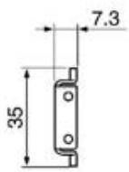
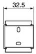
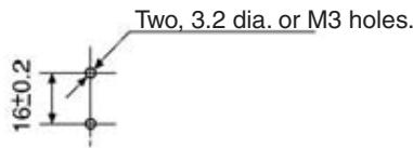
Mounting dimensions
(Unit: mm)
Mounting Dimensions
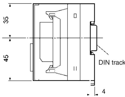
Direct DIN Track Mounting
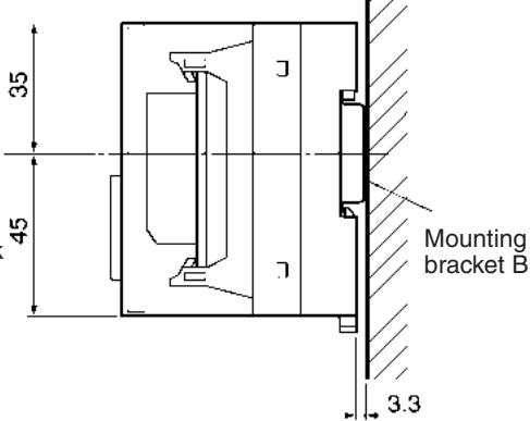
Vertical Panel Mounting
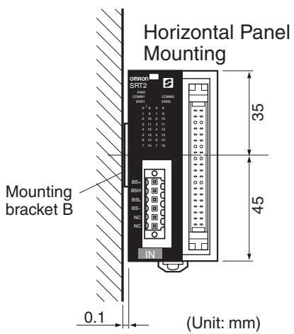
Distance from Duct
Keep the Unit at least 20mm away from the upper and lower ducts.
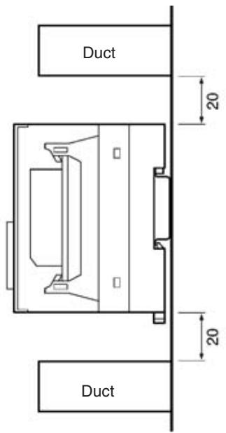
(Unit: mm)
5-2-4 SRT2-OD32ML (-1) Connector Terminals with 32 Transistor Outputs
Specifications
The following tables show the ratings and output specifications for the SRT2-OD32ML (-1).
Ratings
| Item | Specification |
| Models | SRT2-OD32ML, SRT2-OD32ML-1 |
| Output points/Connection type | SRT2-OD32ML: 32 points (NPN)/MIL connector outputSRT2-OD32ML-1: 32 points (PNP)/MIL connector output |
| Connection | Communications power:By communications connector (included as standard)Output:MIL connector or MIL-compatible Cables (both sold separately) (see page 243)I/O power:MIL connector |
| Power supply type | Multiple power supplies |
| Communications power supply voltage | 14 to 26.4 V DC(Power can be supplied from the communications cable) |
| I/O power supply voltage | 20.4 to 26.4 V DC (24 V DC +10%/_-15%) |
| Current consumption(See note.) | Communications power: 70 mA max. at 24 V DC |
| Noise immunity | 1.5 kVp-p with a pulse width of 0.1 to 1 μs and a rise time of 1 ns (tested with impulse noise simulator) |
| Vibration resistance | 10 to 150 Hz, 0.7-mm double amplitude or 50 m/s² |
| Shock resistance | 150 m/s² |
| Dielectric strength | 500 V AC (between insulated circuits) |
| Ambient temperature | Operating: -10 to 55°C (with no icing or condensation)Storage: -25 to 65°C (with no icing or condensation) |
| Ambient humidity | Operating: 25% to 85% (with no condensation)Storage: 25% to 85% (with no condensation) |
| Operating environment | No corrosive gases |
| Standard accessory | 1 communications connectorNote Mounting Brackets B (SRT2-ATT02) is sold separately |
| Mounting strength | 50 N |
| Terminal strength | Pulling: As stated belowCommunications connector: 30 NMIL connector: 30 N |
| Tightening torque | Communications connector: 0.25 to 0.3 N • m |
| Node number settings | The node number is set on a DIP switch. (Set the node number before turning ON the Slave.) |
| Weight | Approx. 90 g max. |
Note This is the current consumption when all the maximum simultaneous input points are ON, excluding the current consumption of external loads.
Output Specifications
| Item | Specifications |
| Output current | 0.3 max./point (4 A common) (See note.) |
| Residual voltage | OD32ML: 1.2 V max. (0.3 A DC between each output ter- minal and G) OD32ML-1: 1.2 V max. (0.3 A DC between each output terminal and V) |
| Leakage current | OD32ML: 0.1 mA max. OD32ML-1: 0.1 mA max. |
| ON delay time | 0.5 ms max. |
| OFF delay time | 1.5 ms max. |
| Insulation method | Photocoupler |
| Number of circuits | 32 points/single common circuit |
Note When using the V and G terminals of the MIL connector, make sure that current does not exceed 1 A at each terminal.
Slave Components
The following diagram shows the main components of the SRT2-OD32ML (-) Connector Terminals with Transistor Outputs. The functions of these components are described below.
Communications Connector
Used to connect CompoBus/S communications data (BD H, BD L) and communications
power supply (see page 256). One compatible connector is provided as standard.
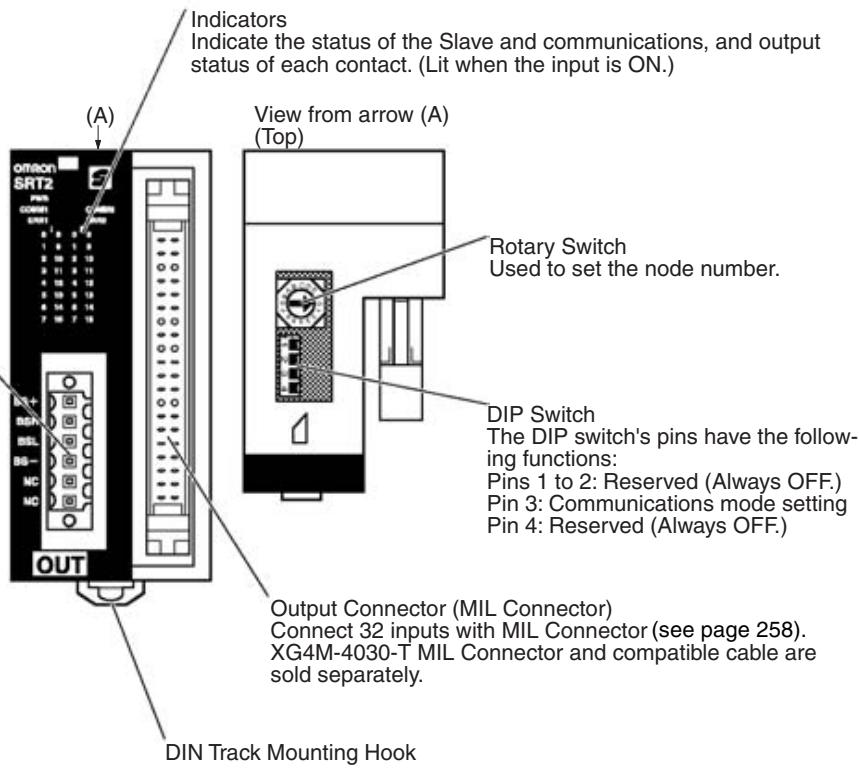
Indicators
The following table shows the meaning of the indicators.
| Indicator | Name | Status | Meaning |
| PWR (green) | Power | ON | The communications power sup-ply is ON. |
| OFF | The communications power sup-ply is OFF. | ||
| COMM1 (yel-low) | Communica-tions | ON | Normal communications on word n. |
| OFF | A communications error has occurred on word n or the Unit is in standby status. | ||
| COMM2 (yel-low) | ON | Normal communications on word n+1. | |
| OFF | A communications error has occurred on word n+1 or the Unit is in standby status. | ||
| ERR1 (red) | Communica-tions error | ON | A communications error has occurred on word n. |
| OFF | Normal communications on word n or the Unit is in standby status. | ||
| ERR2 (red) | ON | A communications error has occurred on word n+1. | |
| OFF | Normal communications on word n+1 or the Unit is in standby sta-tus. | ||
| I (yellow) 0 to 15 (16 outputs) | Outputs | ON | The corresponding output on word n is ON. |
| OFF | The corresponding output is OFF or the Unit is in standby status. | ||
| II (yellow) 0 to 15 (16 inputs) | ON | The corresponding output on word n+1 is ON. | |
| OFF | The corresponding output on word n+1 is OFF or the Unit is in standby status. |
Switch Settings
Note Word n is the first word allocated in the Unit.
The rotary switch and the DIP switch are located on the upper part of the Connector Terminal.
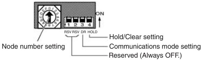
Note Always turn OFF the Slave before changing switch settings.
Node Number Settings
Set the node number in hexadecimal with the rotary switch as shown in the following table.
| Node number | Setting (Hex) | Node number | Setting (Hex) |
| 0 | 0 | 8 | 8 |
| 1 | 1 | 9 | 9 |
| 2 | 2 | 10 | A |
| 3 | 3 | 11 | B |
| 4 | 4 | 12 | C |
| 5 | 5 | 13 | D |
| 6 | 6 | 14 | E |
| 7 | 7 | 15 | F |
Note
- The node number of the 32-point Slave must be set to an even number. If an odd number is input, the odd number less one will be set in the Slave.
- The possible range of node numbers varies with the type of Master and settings in the Master. Refer to 2-1 Communications Specifications for details.
Communications Mode Settings
The following communications modes are set with pin 3 of the DIP switch as shown below.
| SW3 | Communications mode | Communications distance | Communications baud rate | Communications cycle time |
| OFF | High-speed Communications Mode | 100 m max. | 750 kbps | 0.5 or 0.8 ms |
| ON | Long-distance Communications Mode | 500 m max. | 93.75 kbps | 4.0 or 6.0 ms |
Note Make sure that the communications mode of the Slave is the same as that of the Master Unit. If the communications modes are not the same, normal communications with the Master Unit will not be possible. The operating status of the Slave can be verified with LED indicators. Refer to 6-5-1 Indicators.
Hold/Clear Outputs for Communications Errors
Pin 4 is used to set the output data status when a communications error occurs, as shown in the following table.
| Pin 4 (HOLD) | Setting |
| OFF | Clear output status |
| ON | Maintain output status |
Internal Circuits
SRT2-OD32ML
The following diagram shows the internal circuits for the SRT2-OD32ML.
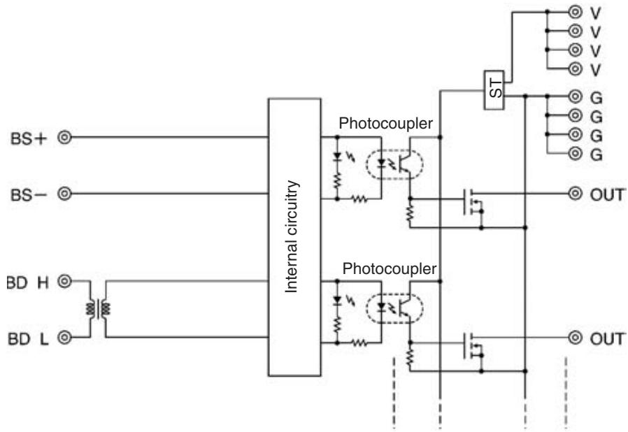
SRT2-OD32ML-1
The following diagram shows the internal circuits for the SRT2-OD32ML-1.
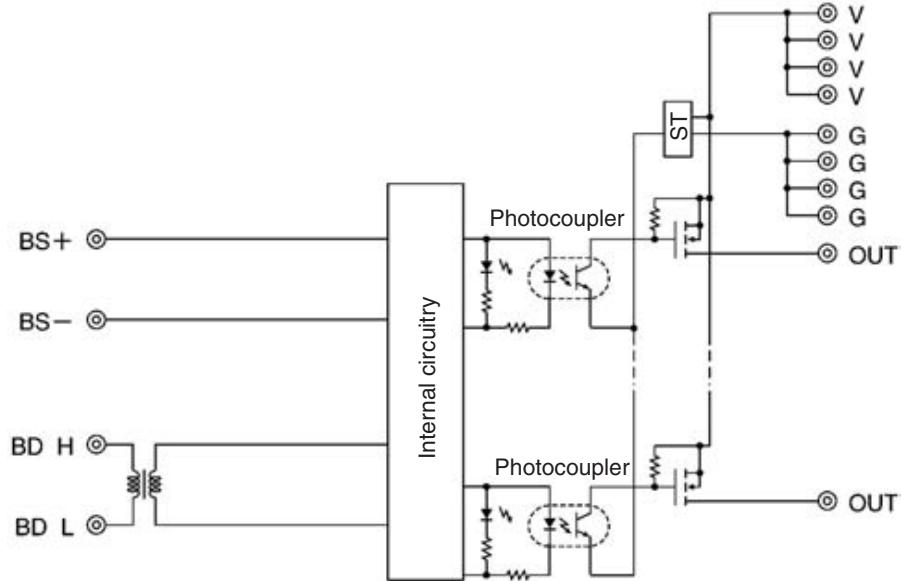
Wiring
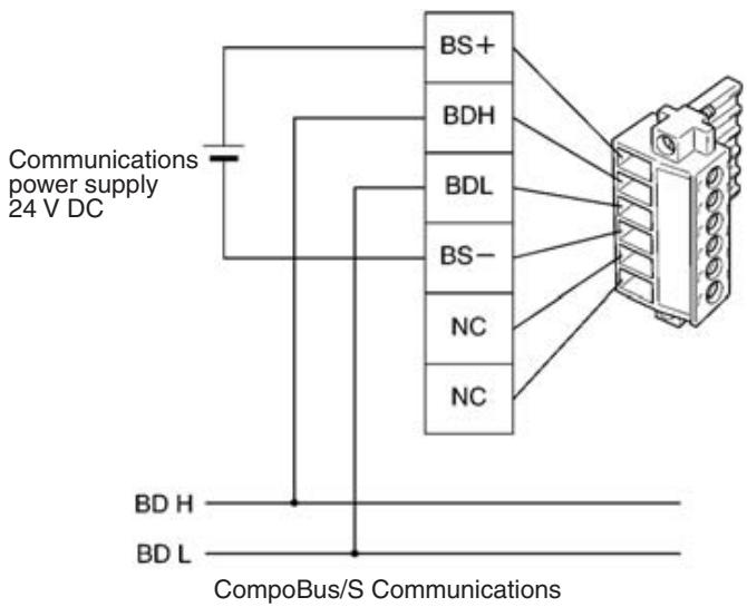
Communications Connector Pin Arrangement
The communications connector (provided as standard) can be ordered
as the following product:
BL3.5/6F (product no. 160668) manufactured by Weidmuller Co., Ltd.
Note 1. OMRON recommends the following products manufactured by Weidmuller Co., Ltd. for use as crimp terminals.
Sleeve (product no. 046290)
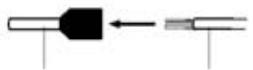
Crimp terminal Cable
For inserting 2 wires (product no. 901851)
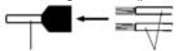
Crimp terminal Ca
Cable
Insert cable then crimp
- The following special tool is available: Crimper PZ1.5 (product no. 900599) manufactured by Weidmuller Co., Ltd.
MIL Connector Pin Arrangement
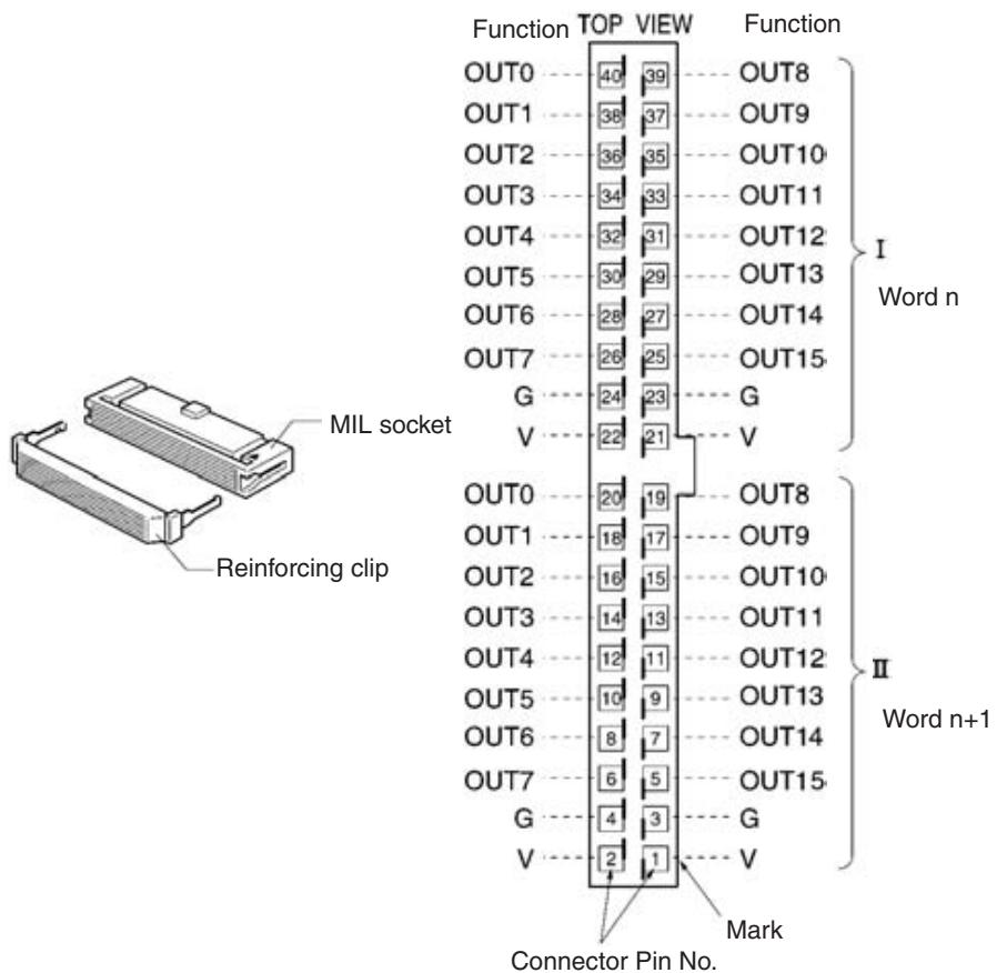
| Name | Model |
| MIL connector | XG4M-4030-T |
Note The XG4M-4030-T MIL Connector is not provided as standard and must be ordered separately.
Terminal Arrangement and Wiring Method

SRT2-OD32ML
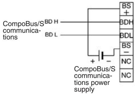
SRT2-OD32ML-1
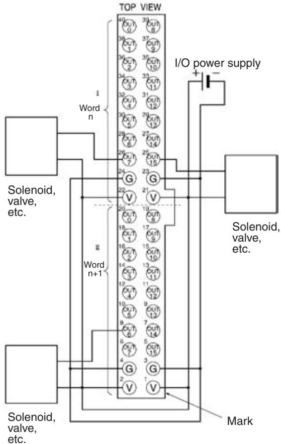
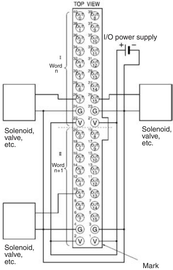
I/O Allocations
Provided that the first word of the Connector Terminal with 32 transistor outputs allocated to the Master Unit is n, the pin numbers of the MIL connector correspond to the following word and bit allocations.
| Word n | 15 | 14 | 13 | 12 | 11 | 10 | 9 | 8 | 7 | 6 | 5 | 4 | 3 | 2 | 1 | 0 |
| 25 | 27 | 29 | 31 | 33 | 35 | 37 | 39 | 26 | 28 | 30 | 32 | 34 | 36 | 38 | 40 | |
| Word n+1 | 5 | 7 | 9 | 11 | 13 | 15 | 17 | 19 | 6 | 8 | 10 | 12 | 14 | 16 | 18 | 20 |
Compatible External Input Devices and Cables
The Connector Terminals with 32 inputs connect to external devices over one of the following method.
1,2,3... 1. Using an XG4A-4030-T MIL Connector (sold separately) to Assemble Your Own Cable For details, refer to MIL Connector Wiring and Assembly on page 258.
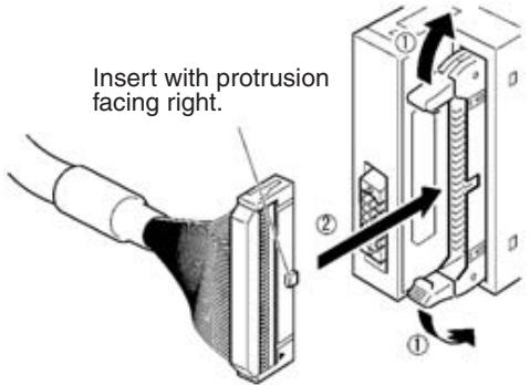
- Connecting with OMRON Products Using an MIL-compatible Cables Manufactured by OMRON Select the MIL-compatible Cable from the following table according to the Connector Terminals and I/O Block to be connected.
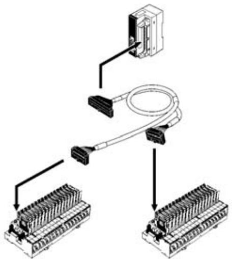
| Slave model | MIL-compatible Cable | Connecting I/O block |
| SRT2-OD32ML | G79-O50-25-D1 (50 cm) | G7TC-OC16/OC08 |
| G79-O75-50-D1 (75 cm) | G70D-SOC16/VSOC16 | |
| G70A-ZOC16-3 | ||
| SRT2-OD32ML-1 | G79-O50-25-D1 (50 cm) | G70A-ZOC16-4 |
| G79-O75-50-D1 (75 cm) | G70D-SOC16-1 | |
| G79-I50-25-D1 (50 cm) | G7TC-OC16-4 | |
| G79-I75-50-D1 (75 cm) | M7F |
Note MIL-compatible cables are not provided as standard and must be ordered separately.
The following cables are available, each of which is provided with a single MIL connector for the Connector Terminal end.
| MIL-compatible cable | Remarks |
| G79-A200C-D1 (2 m) | Wire dia.: AWG28 (other end) |
| G79-A500C-D1 (5 m) | All wires are precut. |
| G79-Y100C-D1 (1 m) | Fork terminals provided to other end. |
| G79-Y200C-D1 (2 m) | Fork terminal: Nippon Tanshi's 161071-M2 |
| G79-Y500C-D1 (5 m) |
The pin numbers of the MIL connector corresponds to the following color wires marked with color dots.
| Pin | Wire color | Dots | Dot color | Pin | Wire color | Dots | Dot color |
| 1 | Light brown | ■ | Black | 21 | Light brown | ■■■ | Black |
| 2 | Red | 22 | Red | ||||
| 3 | Yellow | Black | 23 | Yellow | Black | ||
| 4 | Red | 24 | Red | ||||
| 5 | Light green | Black | 25 | Light green | Black | ||
| 6 | Red | 26 | Red | ||||
| 7 | Gray | Black | 27 | Gray | Black | ||
| 8 | Red | 28 | Red | ||||
| 9 | White | Black | 29 | White | Black | ||
| 10 | Red | 30 | Red | ||||
| 11 | Light brown | ■■ | Black | 31 | Light brown | ■■■■ | Black |
| 12 | Red | 32 | Red | ||||
| 13 | Yellow | Black | 33 | Yellow | Black | ||
| 14 | Red | 34 | Red | ||||
| 15 | Light green | Black | 35 | Light green | Black | ||
| 16 | Red | 36 | Red | ||||
| 17 | Gray | Black | 37 | Gray | Black | ||
| 18 | Red | 38 | Red | ||||
| 19 | White | Black | 39 | White | Black | ||
| 20 | Red | 40 | Red |
Dimensions
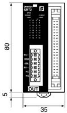

(Unit: mm)
Note For details on wiring dimensions, refer to 5-2-3 SRT2-ID32ML (-1) Connector Terminals with 32 Transistor Inputs.
Mounting Methods
The following mounting methods are available. These methods are the same as those used for mounting Connector Terminals with 8 or 16 inputs.
- DIN track mounting (with no mounting brackets): Refer to page 208.
- Vertical panel mounting (with Mounting Bracket B only): Refer to page 210.
- Horizontal panel mounting (with Mounting Bracket B only): Refer to page 210.
Note 1. The 32-point Connector Terminal cannot be directly panel-mounted with screws. Use the SRT2-ATT02 Mounting Bracket B.
- For details on wiring dimensions, refer to 5-2-3 SRT2-ID32ML (-1) Connector Terminals with 32 Transistor Inputs.
5-2-5 SRT2-MD32ML (-1) Connector Terminals with 16 Transistor Inputs and 16 Transistor Outputs
Specifications
The following tables show the ratings and I/O specifications for the SRT2-MD32ML (-1).
Ratings
| Item | Specification |
| Models | SRT2-MD32ML, SRT2-MD32ML-1 |
| Input points/Connection type | SRT2-MD32ML: 16 input and 16 output points (NPN)/MIL connector input SRT2-MD32ML-1: 16 input and 16 output points (PNP)/MIL connector input |
| Connection | Communications power: By communications connector (included as standard) Input: MIL connector or MIL-compatible Cables (both sold separately) (see page 253) I/O power: MIL connector |
| Power supply type | Multiple power supplies |
| Communications power supply voltage | 14 to 26.4 V DC (Power can be supplied from the communications cable) |
| I/O power supply voltage | 20.4 to 26.4 V DC (24 V DC +10%/_-15%) |
| Current consumption (See note.) | Communications power: 60 mA max. at 24 V DC |
| Noise immunity | 1.5 kVp-p with a pulse width of 0.1 to 1 μs and a rise time of 1 ns (tested with impulse noise simulator) |
| Vibration resistance | 10 to 150 Hz, 0.7-mm double amplitude or 50 m/s² |
| Shock resistance | 150 m/s² |
| Dielectric strength | 500 V AC (between insulated circuits) |
| Ambient temperature | Operating: -10 to 55°C (with no icing or condensation) Storage: -25 to 65°C (with no icing or condensation) |
| Ambient humidity | Operating: 25% to 85% (with no condensation) Storage: 25% to 85% (with no condensation) |
| Operating environment | No corrosive gases |
| Standard accessory | 1 communications connector Note Mounting Bracket B (SRT2-ATT02) is sold separately |
| Mounting strength | 50 N |
| Terminal strength | Pulling: As stated below. Communications connector: 30 N MIL connector: 30 N |
| Tightening torque | Communications connector: 0.25 to 0.3 N • m |
| Node number settings | The node number is set on a DIP switch. (Set the node number before turning ON the Slave.) |
| Weight | Approx. 100 g max. |
Note This is the current consumption when all the maximum simultaneous input points are ON, excluding the current consumption of external sensors.
Input Specifications
| Item | Specifications |
| Input current | 6 mA max./point at 24 V DC 3 mA min./point at 17 V DC |
| ON delay time | 1.5 ms max. |
| OFF delay time | 1.5 ms max. |
| ON voltage | MD32MIL: 17 V DC min. (between each input terminal and V) MD32ML-1: 17 V DC min.(between each input terminal and G) |
| OFF voltage | MD32ML: 5 V DC max. (between each input terminal and V) MD32M-1: 5 V DC max. (between each input terminal and G) |
| OFF current | 1 mA max. |
| Insulation method | Photocoupler |
| Max. simulta- neous input points | 16 points |
| Number of circuits | 16 points/single common circuit |
Output Specifications
| Item | Specifications |
| Output current | 0.3 max./point (4 A common) (See note.) |
| Residual voltage | MD32ML: 1.2 V max. (0.3 A DC between each output termi- nal and G) MD32ML-1: 1.2 V max. (0.3 A DC between each output termi- nal and V) |
| Leakage current | MD32ML: 0.1 mA max. MD32ML-1: 0.1 mA max. |
| ON delay time | 0.5 ms max. |
| OFF delay time | 1.5 ms max. |
| Insulation method | Photocoupler |
| Number of circuits | 16 points/single common circuit |
Note When using the V and G terminals of the MIL connector, make sure that current does not exceed 1 A at each terminal.
Simultaneous Input Points and Installation Spacing
For Connector Terminals with 16 transistor inputs and 16 transistor outputs, the ambient operating temperature places a limit on the maximum number of points that can be turned ON simultaneously.
For example, if Connector Terminals are to be mounted in the direction other than the following directions at an ambient operating temperature of 55^ with all the 16 points turned ON simultaneously, the Connector Terminals must not be mounted closely together.
a. Units mounted upside down
b. Units mounted horizontally with the MIL connectors facing downward
c. Units mounted facing downward
If 16 points of any Unit mounted in the above directions need to be turned ON simultaneously, the spacing of the Units is limited as shown in the following
graph. For example, if the ambient operating temperature is 55^ , a minimum space of 10 mm is required between Units.
a. Units mounted upside down
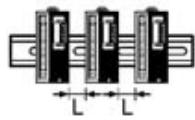
b. Units mounted horizontally with the MIL connectors facing downward

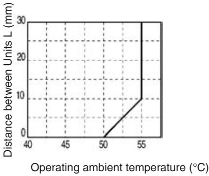
c. Units mounted facing downward
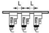
Slave Components
The following diagram shows the main components of the SRT2-MD32ML (-) Connector Terminals with Transistor Inputs and Transistor Outputs. The functions of these components are described below.
Communications Connector
Used to connect CompoBus/S communications data (BD H, BD L)
and communications power supply (see page 256).
One compatible connector is provided as standard.
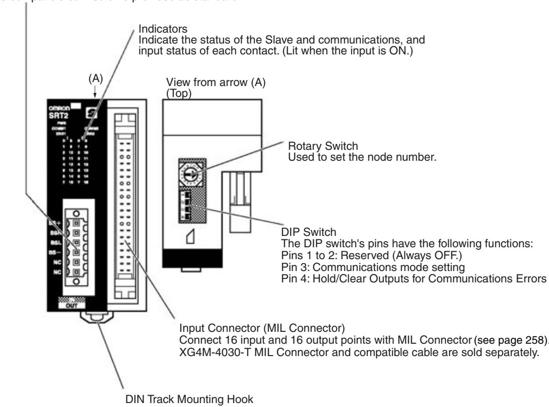
Indicators
The following table shows the meaning of the indicators.
| Indicator | Name | Status | Meaning |
| PWR (green) | Power | ON | The communications power supply is ON. |
| OFF | The communications power supply is OFF. | ||
| COMM1 (yellow) | Communi-cations | ON | Normal communications on word m. |
| OFF | A communications error has occurred on word m or the Unit is in standby status. | ||
| COMM2 (yellow) | ON | Normal communications on word n. | |
| OFF | A communications error has occurred on word n or the Unit is in standby status. | ||
| ERR1 (red) | Communi-cations error | ON | A communications error has occurred on word m. |
| OFF | Normal communications on word m or the Unit is in standby status. | ||
| ERR2 (red) | ON | A communications error has occurred on word n. | |
| OFF | Normal communications on word n or the Unit is in standby status. | ||
| I (yellow) 0 to 15 (16 inputs) | I/O | ON | The corresponding input on word m is ON. |
| OFF | The corresponding input is OFF or the Unit is in standby status. | ||
| II (yellow) 0 to 15 (16 outputs) | ON | The corresponding output on word n is ON. | |
| OFF | The corresponding output on word n is OFF or the Unit is in standby status. |
Switch Settings
Note Word m is the word allocated in the Unit as an input Slave. Word n is the word allocated in the Unit as an output Slave.
The rotary switch and the DIP switch are located on the upper part of the Connector Terminal.
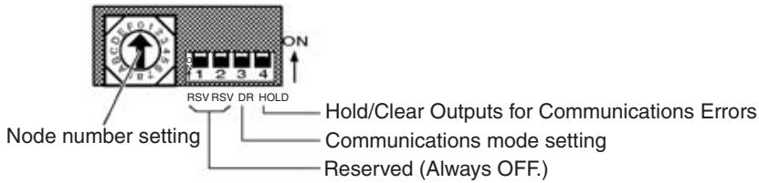
Note Always turn OFF the Slave before changing switch settings.
Node Number Settings
Set the node number in hexadecimal with the rotary switch as shown in the following table.
| Node number | Setting (Hex) | Node number | Setting (Hex) |
| 0 | 0 | 8 | 8 |
| 1 | 1 | 9 | 9 |
| 2 | 2 | 10 | A |
| 3 | 3 | 11 | B |
| 4 | 4 | 12 | C |
| 5 | 5 | 13 | D |
| 6 | 6 | 14 | E |
| 7 | 7 | 15 | F |
Note
- The 32-point Slave is handled as a 16-point input Slave and a 16-point output Slave. The node number of the 32-point Slave must be set to an even number. If an odd number is input, the odd number less one will be set in the Slave.
- The possible range of node numbers varies with the type of Master and settings in the Master. Refer to 2-1 Communications Specifications for details.
Communications Mode Settings
The following communications modes are set with pin 3 of the DIP switch as shown below.
| Pin 3 | Communications mode | Communications distance | Communications baud rate | Communications cycle time |
| OFF | High-speed Communications Mode | 100 m max. | 750 kbps | 0.5 or 0.8 ms |
| ON | Long-distance Communications Mode | 500 m max. | 93.75 kbps | 4.0 or 6.0 ms |
Note Make sure that the communications mode of the Slave is the same as that of the Master Unit. If the communications modes are not the same, normal communications with the Master Unit will not be possible. The operating status of the Slave can be verified with LED indicators. Refer to 6-5-1 Indicators for details.
Hold/Clear Outputs for Communications Error
Pin 4 is used to set the output data status when a communications error occurs, as shown in the following table.
| Pin 4 (HOLD) | Output setting |
| OFF | Clear output status. |
| ON | Maintain output status. |
Internal Circuits
SRT2-MD32ML
The following diagram shows the internal circuits for the SRT2-MD32ML.
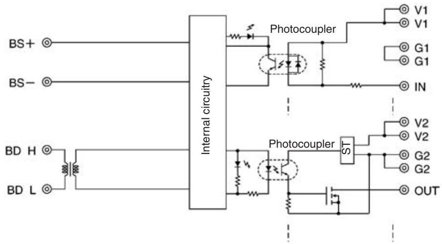
SRT2-MD32ML-1
The following diagram shows the internal circuits for the SRT2-MD32ML-1.
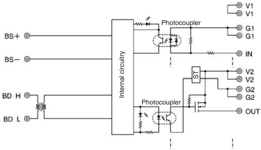
Wiring
Communications Connector Pin Arrangement
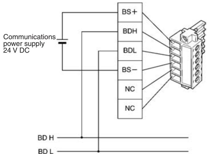
CompoBus/S Communications
The communications connector (provided as standard) can be ordered as the following product:
BL3.5/6F (product no. 160668) manufactured by Weidmuller Co., Ltd.
Note 1. OMRON recommends the following products manufactured by Weidmuller Co., Ltd. for use as crimp terminals.
Sleeve (product no. 046290)
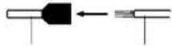
Crimp terminal
Cable
For inserting 2 wires (product no. 901851)
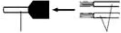
Crimp terminal
Cable
Insert cable then crimp
- The following special tool is available:
Crimper PZ1.5 (product no. 900599) manufactured by Weidmuller Co., Ltd.
MIL Connector Pin Arrangement
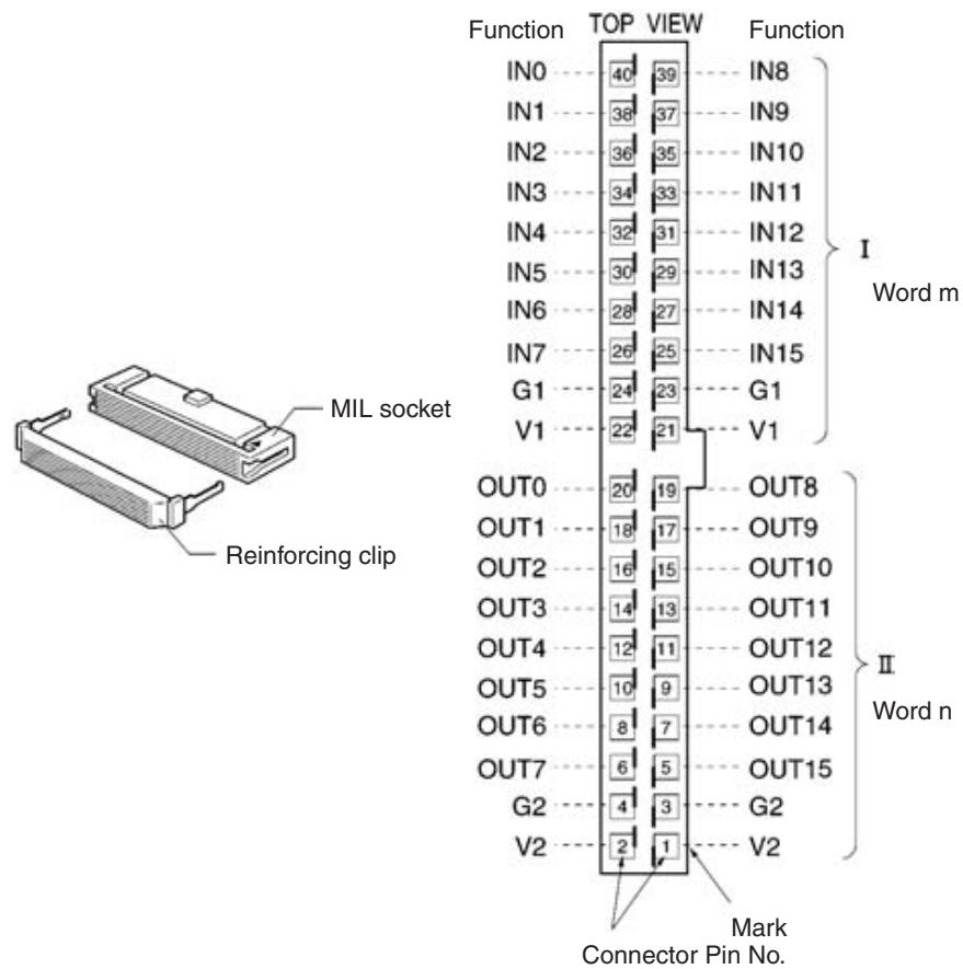
| Name | Model |
| MIL connector | XG4M-4030-T |
Note The XG4M-4030-T MIL Connector is not provided as standard and must be ordered separately.
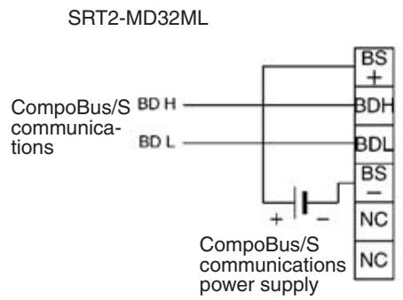
Terminal Arrangement and Wiring Method
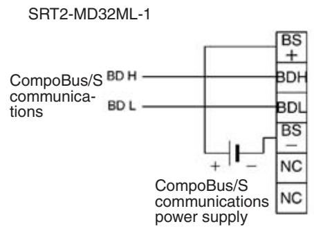
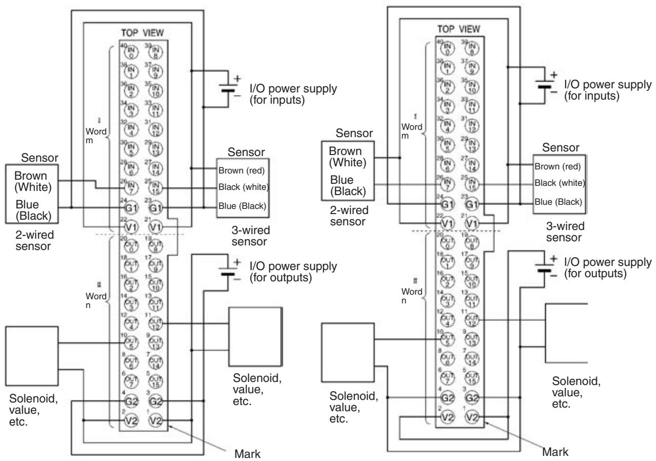
Note In accordance with the changes in the standards for photoelectric sensors and proximity sensors, wire colors have been changed. Colors in parentheses are the old wire colors.
I/O Allocations
Provided that the words of the Connector Terminal with 32 transistor inputs and 32 transistor outputs allocated as input and output Slaves to the Master Unit are m and n, the pin numbers of the MIL connector correspond to the following word and bit allocations.

Compatible External Input Devices and Cables
The Connector Terminals with 32 inputs connect to external devices over one of the following method.
1,2,3... 1. Using an XG4A-4030-T MIL Connector (sold separately) to Assemble Your Own Cable
For details, refer to MIL Connector Wiring and Assembly on page 258.
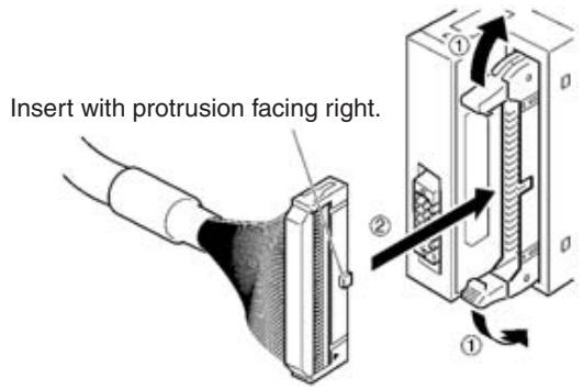
- Connecting with OMRON Products Using an MIL-compatible Cables Manufactured by OMRON
Select the MIL-compatible Cable from the following table according to the Connector Terminals and I/O Block to be connected.
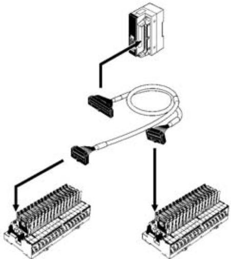
| Slave model | MIL-compatible Cable | Connecting I/O block | Remarks |
| SRT2-MD32ML | G79-M50-25-D1 (50 cm)G79-M75-50-D1 (75 cm) | Inputs:G7TC-ID16/IA16Outputs:G7TC-OC08/OC16G7OD-SOC16/VSOC16G70A-ZOC16-3 | Input and output wires can be distinguished with the following colors.Inputs: RedOutputs: Yellow |
| SRT2-MD32ML-1 | G79-M50-25-D2 (50 cm)G79-M75-50-D2 (75 cm) | Inputs:G70A-ZIM16-5Outputs:G70A-ZOC16-4G70D-SOC16-1 |
Note MIL-compatible cables are not provided as standard and must be ordered separately.
The following cables are available, each of which is provided with a single MIL connector for the Connector Terminal end.
| MIL-compatible cable | Remarks |
| G79-A200C-D1 (2 m) | Wire dia.: AWG28 (other end) |
| G79-A500C-D1 (5 m) | All wires are precut. |
| G79-Y100C-D1 (1 m) | Fork terminals provided to other end. |
| G79-Y200C-D1 (2 m) | Fork terminal: Nippon Tanshi's 161071-M2 |
| G79-Y500C-D1 (5 m) |
The pin numbers of the MIL connector corresponds to the following color wires marked with color dots.
| Pin | Wire color | Dots | Dot color | Pin | Wire color | Dots | Dot color |
| 1 | Light brown | ■ | Black | 21 | Light brown | ■■■ | Black |
| 2 | Red | 22 | Red | ||||
| 3 | Yellow | Black | 23 | Yellow | Black | ||
| 4 | Red | 24 | Red | ||||
| 5 | Light green | Black | 25 | Light green | Black | ||
| 6 | Red | 26 | Red | ||||
| 7 | Gray | Black | 27 | Gray | Black | ||
| 8 | Red | 28 | Red | ||||
| 9 | White | Black | 29 | White | Black | ||
| 10 | Red | 30 | Red | ||||
| 11 | Light brown | ■■ | Black | 31 | Light brown | ■■■■ | Black |
| 12 | Red | 32 | Red | ||||
| 13 | Yellow | Black | 33 | Yellow | Black | ||
| 14 | Red | 34 | Red | ||||
| 15 | Light green | Black | 35 | Light green | Black | ||
| 16 | Red | 36 | Red | ||||
| 17 | Gray | Black | 37 | Gray | Black | ||
| 18 | Red | 38 | Red | ||||
| 19 | White | Black | 39 | White | Black | ||
| 20 | Red | 40 | Red |
Dimensions
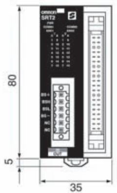
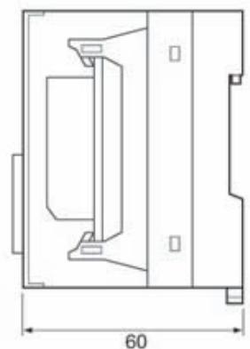
(Unit: mm)
Note For details on wiring dimensions, refer to 5-2-3 SRT2-ID32ML (-1) Connector Terminals with 32 Transistor Inputs.
Mounting Methods
The following mounting methods are available. These methods are the same as those used for mounting Connector Terminals with 8 or 16 inputs.
- DIN track mounting (with no mounting brackets): Refer to page 208.
- Vertical panel mounting (with Mounting Bracket B only): Refer to page 210.
- Horizontal panel mounting (with Mounting Bracket B only): Refer to page 210.
Note 1. The 32-point Connector Terminal cannot be directly panel-mounted with screws. Use the SRT2-ATT02 Mounting Bracket B.
- For details on wiring dimensions, refer to 5-2-3 SRT2-ID32ML (-1) Connector Terminals with 32 Transistor Inputs.
5-2-6 Wiring and Assembly of Communications Connector and MIL Connector for Connector Terminals
Connect the communications cable to the Connector Terminal using the rectangular communications connector provided with the Unit. The Connector Terminals with MIL connectors are used to connect the external I/O. The wiring and assembly methods of square communications connectors and MIL connectors are described here.
The Connector Terminals with sensor connectors are used to connect the external I/O cable connector. The cable connector wiring and assembly methods are the same as for Sensor Terminals, so refer to 3-4-3 Cable Connector Wiring and Assembly for details.
Wiring
A CompoBus/S cable must be connected to a Connector Terminal after the communications data (BD H, BD L), communications power supply (BS+ , BS-), and I/O power supply (G, V) lines are connected to the communications connector (i.e., the connector on the cable end). I/O power is not supplied to 32-point Connector Terminals.
Caution
Be sure to turn OFF the Slave power supply and communications power supply before connecting communications data, communications power supply, or I/O power supply lines, and before attaching or detaching connectors. For the connector, use the communications connector provided with the Connector Terminal.
Use the following procedure to connect the communications data, communications power supply, and I/O power supply lines to the connector.
1,2,3...
- Remove sufficient insulation from the signal wires for a crimp terminal, and twist the exposed wire strands together tightly.

If using VCTF cable, cover the severed end of the insulation with vinyl tape or heat-shrinking tube.
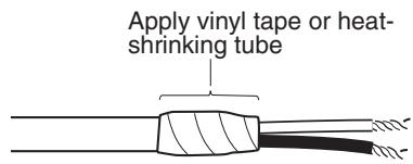
- After attaching a crimp terminal to the exposed signal wires, cover with vinyl tape or heat-shrinking tube.
OMRON recommends the following products manufactured by Weidmuller Co., Ltd. for use as crimp terminals.
Sleeve (product no. 046290)
For inserting 2 wires (product no. 901851)
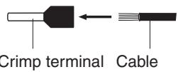
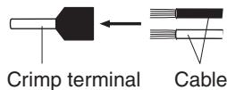
Insert cable then crimp
The following special tool is available:
Crimper PZ1.5 (product number 900599) manufactured by Weidmuller Co., Ltd.
- Paying attention to the orientation of the connector, insert each signal wire into the corresponding hole in the connector, as shown below.
SRT2-V□D□□□(-1)
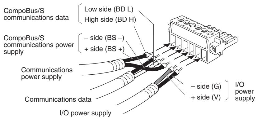
SRT2-□32ML (-1)
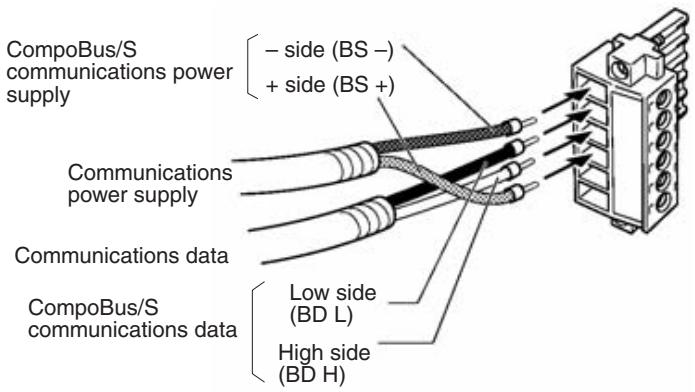
Caution
Before inserting the signal wires, loosen the clamp screws used to secure wires to the connector. If a wire is inserted before the corresponding screw is loosened, the wire may enter the gap behind the connector, and remain unsecured. Use crimp terminals when wiring. Do not attach twisted bare wires directly to connectors.
- Tighten the clamp screws securing each signal wire to the connector. Note that a normal screwdriver has a keystone tip with a flared blade, and may not be able to penetrate deeply enough to reach the screw. Use a small slotted screwdriver of constant width. The correct tightening torque is 0.2 to 0.4N· m .
The following example is for the SRT2-V□D□□□(-1).
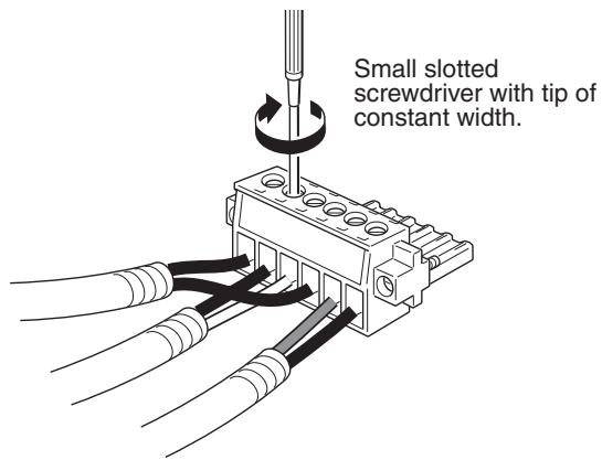
Attaching Connectors
Note Use a fine-tipped screwdriver. The size of the communications Connector Terminal screws is M2.5.
Note
Attach the communications cable fitted with a connector to the connector of the Connector Terminal.
- The direction of the connector depends on the Connector Terminal node model. Communications connectors of 8-point and 16-point Connector Terminals lie horizontally, and the communications connectors of 32-point Connector Terminals are positioned vertically. Check the direction of the connector carefully before inserting it.
- Check that the communications cables are a sufficient length when connecting to prevent them from being pulled out or bent over. Do not place heavy objects on the cable cord. Doing so may cause the cables to break.
1,2,3...
- Attach the communications cable connector to the connector of the Connector Terminal as shown in the following figure. The following example is for the SRT2-V□D□□□(-1).
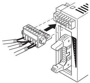
- Tighten the connector screws to secure the connector to the Connector Terminal. The correct tightening torque is 0.2 to 0.4N· m
MIL Connector Wiring and Assembly
Use the procedure below to assemble a cable using the following MIL connectors.
SRT2-V□D16ML (-1): XG4M-2030-T (20-pin MIL Connector)
SRT2-□D32ML (-1): XG4M-4030-T (40-pin MIL Connector)
The following procedure is an example to assemble the 20-pin MIL Connector. The same procedure will apply if the 40-pin MIL Connector is used.
1,2,3...
- Using a fine-tipped screwdriver, release both sides of the plug to separate the MIL socket into its contact and cover components. The contact component of the socket has two small hooks on each side. Release both sides of the cover from these hooks one by one, taking care not to forcefully unhook one side only.
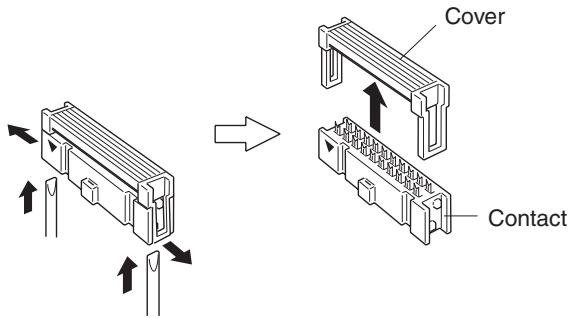
- Insert the flat cable between the cover and contact components separated in 1 above, then, after making sure that each cable wire is placed in the correct position on the contact component, lock the cover and contact components together. Use a vise or similar tool to press the components together
firmly until the hooks engage.
The following cables can be used with MIL connectors.
- 1.27-mm-pitch flat cable AWG28 (7-wire twisted cable)
- UL2651 (standard cable)
- UL20012 (fabric cable)
- UL20028 (color-coded cable)

- If necessary, fold the cable back over as shown and lock on a reinforcing clip.
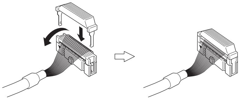
- Insert the newly assembled MIL connector into the Connector Terminal.
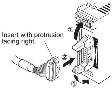
5-3 Remote I/O Modules
5-3-1 SRT□-□D16P Remote I/O Modules
Specifications
The following tables show the ratings and I/O specifications for the SRT□-D16P.
Ratings
| Item | Specification | |
| Models | SRT1-ID16PSRT2-ID16P | SRT1-OD16PSRT2-OD16P |
| I/O points | 16 input points | 16 output points |
| Internal I/O circuit common | NPN (+ common) | NPN (− common) |
| Mounting method | PCB mounting with I/O terminals soldered | |
| Communications mode | SRT1-□D16P: High-speed communications modeSRT2-□D16P: High-speed Communications Mode or Long-distance Communications Mode | |
| Power supply type | --- | |
| Communications power supply voltage | 20.4 to 26.4 V DC | |
| I/O power supply voltage | 24 V DC +10%/-15% | |
| Current consumption (See note.) | 60 mA max. | 20 mA max. |
| Ambient temperature | Operating: 0 to 55°C (with no icing or condensation)Storage: -20 to 65°C (with no icing or condensation) | |
| Ambient humidity | Operating: 35% to 85% (with no condensation)Storage: 25% to 85% (with no condensation) | |
| Dielectric strength | 500 V AC for 1 minute(1-mA sensing current, between insulated circuits) | |
| Node number settings | The node number is set on the address terminal.(Set the node number before turning ON the Slave.) | |
| Weight | 35 g max. | |
Note The current consumption is the value with all points turned ON excluding the current consumption of the external sensors connected to the Module inputs and the current consumption of the loads connected to the Module outputs.
Characteristics
| Item | Specification |
| 5-V output current | 20 mA max. (at 5 V±0.5 V) |
| LED drive current (COMM, ERR) | 10 mA max. (5 V DC) |
| SW carry current (ADR0 to 3, HOLD) | 1 mA max. |
Input Specifications
| Item | Specification |
| Input current | 2 mA max./point |
| ON delay time | 1.5 ms max. |
| OFF delay time | 1.5 ms max. |
| ON voltage | 15 V DC min. (between each input terminal and BS+ terminal) |
| OFF voltage | 5 V DC max. (between each input terminal and BS+ terminal) |
Output Specifications
| Item | Specification |
| Rated output current | 0.2 A/point, 0.6 A/common |
| Residual voltage | 0.6 V max. (between each output terminal and G terminal at 0.2 A) |
| Leakage current | 0.1 mA max. (between each output terminal and G terminal at 24 V DC) |
| ON delay time | 0.5 ms max. |
| OFF delay time | 1.5 ms max. |
Slave Components
The following diagram shows the main components of SRT1-OD16P Remote I/O Modules. The function of these components are described below.
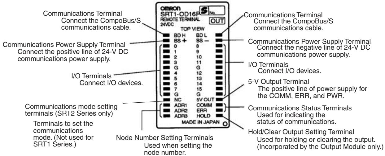
Indicators
The following table shows the meaning of the indicators.
| Indicator | Status | Meaning |
| COMM (yellow) | Low | Normal communications. |
| Hi | A communications error has occurred or the Unit is in standby status. | |
| ERR (red) | Low | A communications error has occurred. |
| Hi | Normal communications or the Unit is in standby status. |
Communications Mode, Node Number and Output HOLD/CLEAR Mode
Set the node number with the NC, ADR1 through ADR3, and hold/clear output setting terminals.
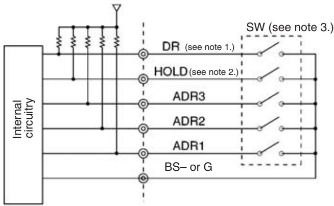
Note
- The DR terminal is not used by the SRT1 Series.
- The HOLD terminal is not used by the Input Module.
- Low: The input bit is ON. Hi: The input bit is OFF.
Note The HOLD terminal is not used by the Input Module.
Communications Mode Settings (SRT2 Series Only)
The following communications modes are set with the communications mode setting terminal (DR) as shown below.
| DR | Comunica-tions mode | Communica-tions distance | Communica-tions baud rate | Communica-tions cycle time |
| Hi | High-speed Com-munications Mode | 100 m max. | 750 kbps | 0.5 or 0.8 ms |
| Low | Long-distance Communications Mode | 500 m max. | 93.75 kbps | 4.0 or 6.0 ms |
Communications mode settings are possible for SRT2-series Slaves only. SRT1-series Slaves are always in high-speed communications mode.
Note Make sure that the communications mode of the Slave is the same as that of the Master Unit. If the communications modes are not the same, normal communications with the Master Unit will not be possible. The operating status of the Slave can be verified with LED indicators. The COMM terminal corresponds to the COM indicator and ERR terminal corresponds to the ERR indicator.
Node Number Settings
Set the node number with terminals ADR1 through ADR3, as shown in the following table.
| Node number | ADR3 (8) | ADR2 (4) | ADR1 (2) |
| 0 | Hi | Hi | Hi |
| 2 | Hi | Hi | Low |
| 4 | Hi | Low | Hi |
| 6 | Hi | Low | Low |
| 8 | Low | Hi | Hi |
| 10 | Low | Hi | Low |
| 12 | Low | Low | Hi |
| 14 | Low | Low | Low |
Note 1. Low: The input bit is ON. Hi: The input bit is OFF.
- The node number should be an even number.
- The terminals are pulled up to the 5-V line internally.
Note The actual node number setting range depends on the type of PLC in which the Master is mounted as well as the Master's settings. Refer to 2-1 Communications Specifications for details.
Hold/Clear Output Setting for Communications Errors (Output Module Only)
The HOLD terminal is used to set the output data status when a communications error occurs, as shown in the following table.
| HOLD | Setting |
| Hi | Output status is cleared when a communications error occurs. |
| Low | Output status is maintained. |
Internal Circuits
The following diagram shows the internal circuits for the SRT□-ID16P (16 inputs).
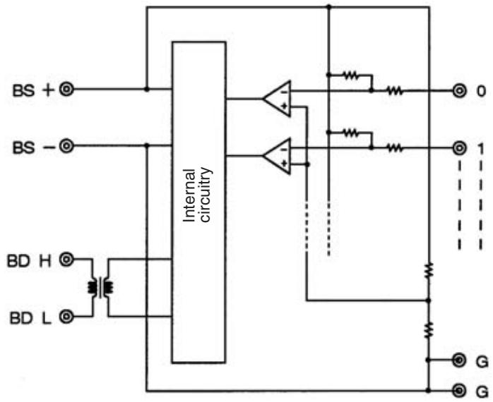
The following diagram shows the internal circuits for the SRT□-OD16P (16 outputs).
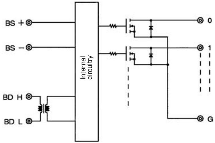
External Connections
The following diagram shows the external connections for the SRT□-ID16P (16 inputs).
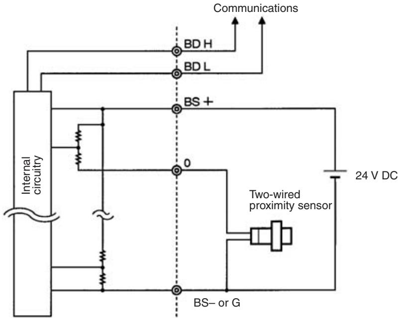
The following diagram shows the external connections for the SRT□-OD16P (16 outputs).
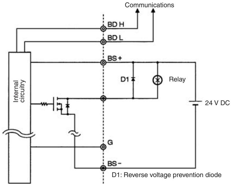
Connecting Communications Status Indicators
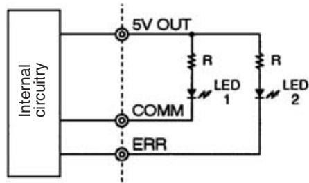
R: LED current limiting resistor
LED1: LED for COMM
LED2: LED for ERR
The maximum current for LED1 and LED2 is 10mA .
Precautions on Inner-layer Pattern Connecting BD H and BD L Terminals
The 5-V output terminals have positive power supplies (maximum output current of 20mA ) for the ERR and COMM LEDs. Recommended LED colors are red for ERR and yellow for COMM.
The pattern connecting terminals BD H and BD L should be as short and as straight as possible. The following precautions should also be observed.
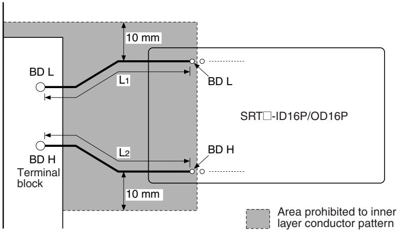
- Conductor Pattern Length
The length of the conductors in the pattern connecting the BD L and BD H terminals of the terminal block to those of either SRT□-ID16P or SRT□-OD16P (L_1,L_2) must satisfy the following conditions.
$$ L _ {1} + L _ {2} \leq 1 0 c m $$
$$ \mathrm {L} _ {1} \approx \mathrm {L} _ {2} (\text {W i t h i n r a t i o o f 1 . 5}) $$
- Conductor Pattern Width
The width of the conductor in the pattern connecting the BD L and BD H terminals of the terminal block to those of either SRT□-ID16P or SRT□-OD16P must be sufficient to carry a current of 250 mA DC, and must also not exceed 0.3 mm (0.3 mm recommended).
-
Area Prohibited to Inner Layer Conductor Pattern
-
Do not create another conductor pattern within 10 ~mm of the pattern connecting the BD L and BD H terminals of the terminal block to those of either SRT□-ID16P or SRT□-OD16P.
Precautions on Crossing Conductors
When it is necessary for the conductors of the pattern connecting the BD L and BD H terminals of the terminal block to those of either SRT□-ID16P or SRT□-OD16P to cross, be sure to create one end on the soldered surface of the circuit board, and make the conductors cross between the terminal block and the SRT□-ID16P or SRT□-OD16P.
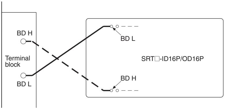
Precautions on Bending Conductor Pattern
When it is necessary for the conductors of the pattern connecting the BD L and BD H terminals of the terminal block to those of either SRT□-ID16P or SRT□-OD16P to change direction, make sure the direction does not veer at a right angle. Keep the direction change within 45^ .
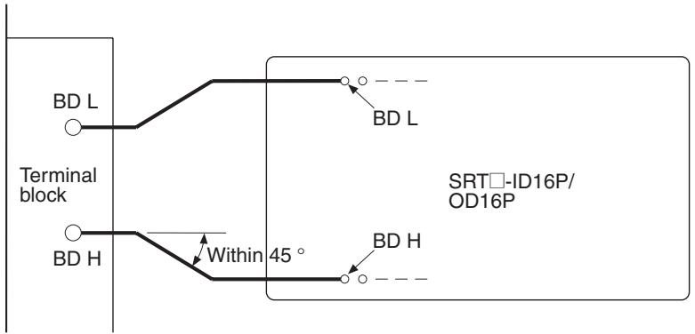
Noise Protection Circuit
Add the following protection circuit if noise is generated from the power supply, input section, or output section.
| Power supply noise protection circuit | Input section noise protection circuit | Output section noise protection circuit |
| L: Coil for the common mode (100 μH min.) Install the coil near the SRT☐. V: 24 V DC (Even if a separate power supply is used, the same kind of protection is recommended.) | R1: Resistor for limiting photocoupler input current D: Photocoupler protection diode C: Noise absorption condenser R2: Resistor for limiting operating level PHC: Photocoupler V: DC power supply Recommended circuit example: R1: 2.7 kΩ; 1/2 W R2: 390 Ω; 1/4 W C: 50 V; 0.1 μF min. (However, these are only examples and are not guaranteed values. Construct the circuit in accordance with the characteristics of the input device to be connected.) | PLC: Photocoupler BS+ R 0 to 15 SRT□ G C: 0.1 μF min. R: Limiting resistor SA: Varistor D: Back-electromotive force protection diode PHS: Photo coupler V: DC power supply |
Note 1. Mounting and PCB Cleaning:
- If a soldering iron is used to solder the circuit, make sure that the circuit is soldered within 3~s at 280 to 300^ .
- If a soldering tub is used to solder the circuit, make sure that the circuit is soldered within 5 s at 260^ maximum.
- Do not pass through a reflow furnace. If it is necessary to pass through a reflow furnace, after reflow processing manually apply soldering only to the main parts.
- Do not apply strong acid or alkali solvent to clean the flux. Also, do not apply ultrasonic cleaning.
2. NC Terminal:
- The NC terminal is used internally. Therefore, do not connect anything to the NC terminal.
Inner-layer Pattern for Noise Protection
When adding a noise protection circuit to the input or output section, create inner-layer patterns as follows:
- There must be at least 2.54mm between the adjacent inner-layer patterns of the external and internal circuits.
- The inner-layer pattern of the external circuit must be kept at least 10mm from each terminal of the SRT□-ID16P or SRT□-OD16P,
No parts must be mounted on the soldered surfaces around the SRT- -ID16P or SRT-OD16P.
Example: SRT1-ID16P
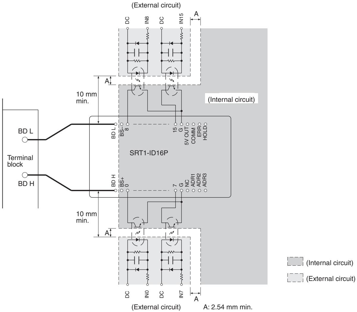
SRT□-ID16P/OD16P Dimensions
The following diagram shows the dimensions for the SRT□-ID16P/OD16P. All dimensions are in mm.
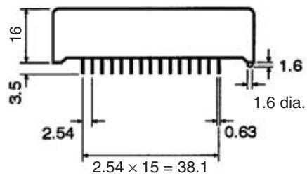
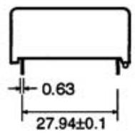
PCB Dimensions (Top View)
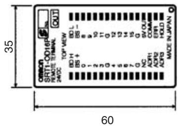
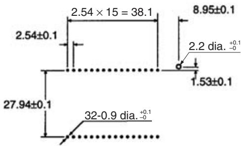
No cumulative tolerance allowed.
5-4 Water-resistant Terminals
5-4-1 SRT2-ID□□CL (-1) Water-resistant Terminals with 4 or 8 Transistor Inputs
Specifications
The following tables show the ratings and input specifications for the SRT2-ID□□CL (-1).
Ratings
| Item | Specification |
| Models | SRT2-ID04CL, SRT2-ID04CL-1, SRT2-ID08CL, SRT2-ID08CL-1 |
| I/O points | SRT2-ID04CL: 4 input points (NPN) SRT2-ID04CL-1: 4 input points (PNP) SRT2-ID08CL: 8 input points (NPN) SRT2-ID08CL-1: 8 input points (PNP) |
| Connection | Communications XS2C-D4S7: Connector Socket Assembly (female) (Crimp terminals/Solder terminals) Inputs XS2G-D4□□: Connector Plug Assembly (male) (Crimp terminals/Solder terminals) XS2H-D421-□□□: Connector with cable (male plug on one end) XS2W-D42□-□□□: Connectors with cable (Socket/Plug on both ends) I/O power XS2C-D4□□: Connector Socket Assembly (female) (Crimp terminals/Solder terminals) XS2F-D42□-□80-A: Connector with cable (female socket on one end) |
| Power supply type | Multiple power supplies |
| Communications power supply voltage | 14 to 26.4 V DC (Power can be supplied from the communications cable) |
| I/O power supply voltage | 20.4 to 26.4 V DC (24 V DC +10%/_-15%) |
| I/O power supply current | 2.4 A max. |
| Current consumption (See note.) | Communications power: 50 mA max. at 24 V DC |
| Noise immunity | 1.5 kVp-p with a pulse width of 0.1 to 1 μs and a rise time of 1 ns (tested with impulse noise simulator) |
| Vibration resistance | 10 to 150 Hz, 0.7-mm double amplitude or 50 m/s² |
| Shock resistance | 150 m/s² |
| Dielectric strength | 500 V AC (between insulated circuits) |
| Insulation resistance | 20 MΩ min. (between insulated circuits) |
| Ambient temperature | Operating: -10 to 55°C (with no icing or condensation) Storage: -25 to 65°C (with no icing or condensation) |
| Ambient humidity | Operating: 25% to 85% (with no condensation) Storage: 25% to 85% (with no condensation) |
| Operating environment | No corrosive gases |
| Enclosure rating | IP67 |
| Mounting method | M5 screws |
| Terminal strength | 100N |
| Node number settings | The node number is set on a rotary switch. (Set the node number before turning ON the Slave.) |
| Weight | SRT2-ID04CL (-1): 180 g max. SRT2-ID08CL (-1): 240 g max. |
Note This is the current consumption when all the maximum simultaneous input points are ON, excluding the current consumption of external sensors.
Input Specifications
| Item | Specifications |
| Input current | 6 mA max./point at 24 V DC 3 mA min./point at 17 V DC |
| ON delay time | 1.5 ms max. |
| OFF delay time | 1.5 ms max. |
| ON voltage | ID04CL/ID08CL: 15 V DC min. (between each input terminal and V) ID04CL-1/ID08CL-1: 15 V DC (between each input termina- nal and G) |
| OFF voltage | ID04CL/ID08CL: 5 V DC max. (between each input terminal and V) ID04CL-1/ID08CL-1: 5 V DC max. (between each input terminal and G) |
| OFF current | 1 mA max. |
| Insulation method | Photocoupler |
| Input indicator | LED (yellow) |
| Number of circuits | ID04CL (-1): 4 points/single common circuit ID08CL (-1): 8 points/single common circuit |
Slave Components
The following diagram shows the main components of the SRT2-ID□□CL (-□) Water-resistant Terminals with Transistor Inputs. The functions of these components are described below.
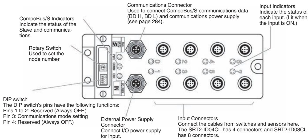
Indicators
The following table shows the meaning of the indicators.
| Indicator | Name | Status | Meaning |
| PWR (green) | Power | ON | The communications power supply is ON. |
| OFF | The communications power supply is OFF. | ||
| COMM (yellow) | Communications | ON | Normal communications. |
| OFF | A communications error has occurred or the Unit is in standby status. | ||
| ERR (red) | Communications error | ON | A communications error has occurred. |
| OFF | Normal communications or the Unit is in standby status. | ||
| IN0 to 3 (4 inputs)IN0 to 7 (8 inputs) (yellow) | Inputs | ON | The corresponding input is ON. |
| OFF | The corresponding input is OFF or the Unit is in standby status. |
Switch Settings
The rotary switch and the DIP switch are located under the transparent cover.
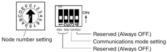
Note 1. Always turn OFF the Slave before changing switch settings.
- Always set all the reserved pins to OFF, or otherwise the Unit may not operate normally.
Node Number Settings
Set the node number in hexadecimal with the rotary switch as shown in the following table.
| Node number | Setting (Hex) | Node number | Setting (Hex) |
| 0 | 0 | 8 | 8 |
| 1 | 1 | 9 | 9 |
| 2 | 2 | 10 | A |
| 3 | 3 | 11 | B |
| 4 | 4 | 12 | C |
| 5 | 5 | 13 | D |
| 6 | 6 | 14 | E |
| 7 | 7 | 15 | F |
Note The possible range of node numbers varies with the type of Master and settings in the Master. Refer to 2-1 Communications Specifications for details.
Communications Mode Settings
The following communications modes are set with pin 3 of the DIP.
| Pin 3 | Communications mode | Communications distance | Communications baud rate | Communications cycle time |
| OFF | High-speed Communications Mode | 100 m max. | 750 kbps | 0.5 or 0.8 ms |
| ON | Long-distance Communications Mode | 500 m max. | 93.75 kbps | 4.0 or 6.0 ms |
Note Make sure that the communications mode of the Slave is the same as that of the Master Unit. If the communications modes are not the same, normal communications with the Master Unit will not be possible. The operating status of the Slave can be verified with LED indicators. Refer to 6-5-1 Indicators.
Internal Circuits
SRT2-ID04CL, SRT2-ID08CL
The following diagram shows the internal circuits for the SRT2-ID04-CL and SRT2-ID08CL.
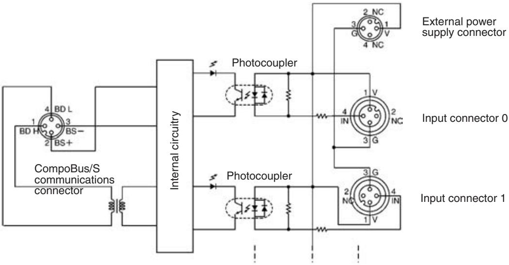
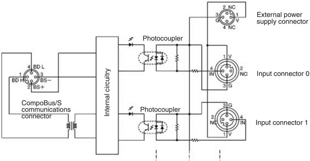
SRT2-ID04CL-1, SRT2-ID08CL-1
Wiring
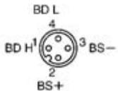
SRT2-ID04CL
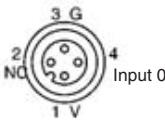
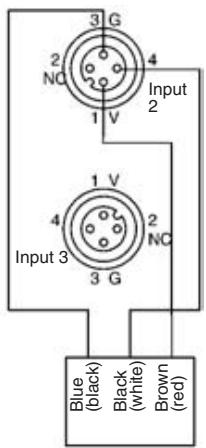
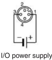
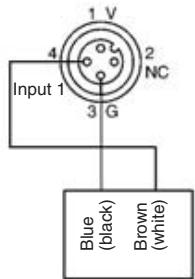
2-wired sensor (or limit switch)
3-wired sensor with NPN output (photoelectric sensor or proximity switch)
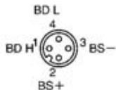
SRT2-ID04CL-1
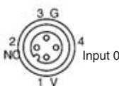
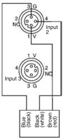
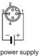
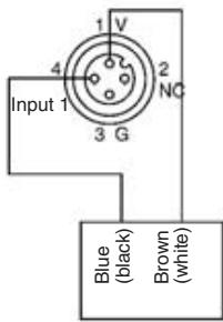
2-wired sensor (or limit switch)
3-wired sensor with PNP output (photoelectric sensor or proximity switch)
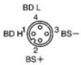
SRT2-ID08CL
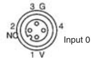
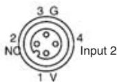
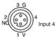
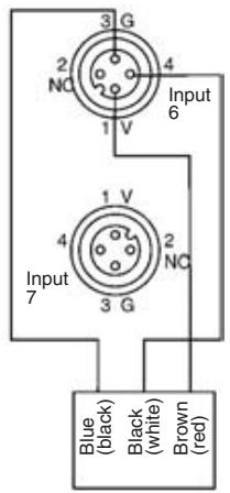
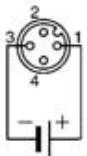
I/O power supply
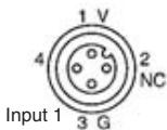
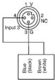
2-wired sensor (or limit switch)
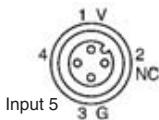
3-wired sensor with NPN output (photoelectric sensor or proximity switch)
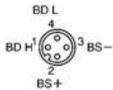
SRT2-ID08CL-1
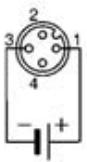
I/O power supply
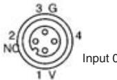
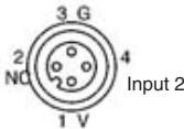
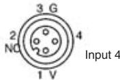
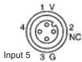

2-wired sensor (or limit switch)
3-wired sensor with PNP output (photoelectric sensor or proximity switch)
Note
- The V terminals are all connected internally, as are the G terminals. Input connectors G and V can be used to supply power to sensors, provided that the total current flow through these connectors is less than 2.4 A when input power supply is provided to the external power supply connector. Connect external power supply if the total current flow is 2.4 A or more.
- Wire colors have been changed. Colors in parentheses are the old wire colors.
Dimensions
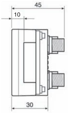
SRT2-ID04CL, SRT2-ID04CL-1
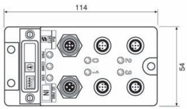
Mounting dimensions
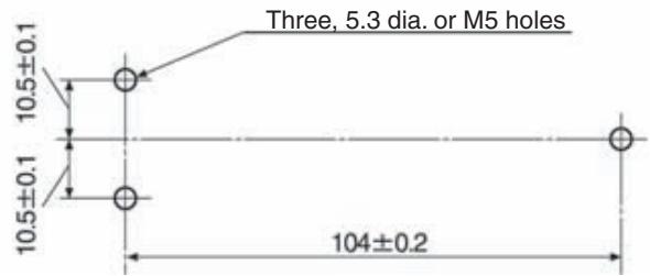
(Unit: mm)
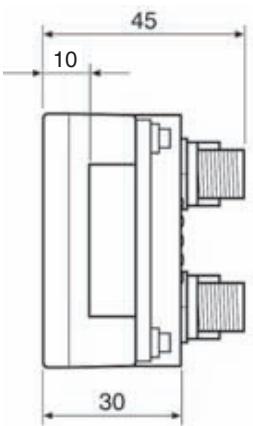
SRT2-ID08CL, SRT2-ID08CL-1
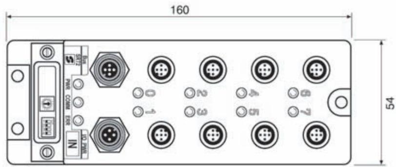
Mounting dimensions
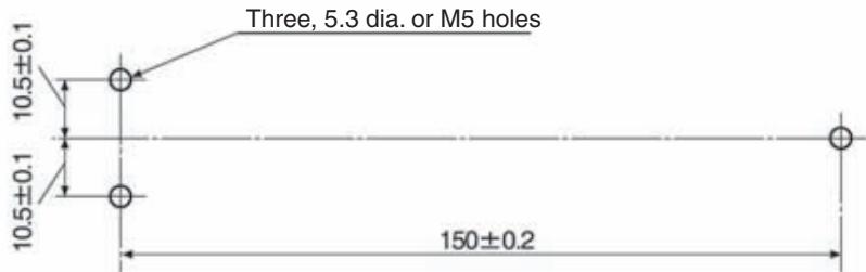
(Unit: mm)
Communications Cable, I/O Power Supply, and I/O Wiring
Communications Cable Wiring
Use the following connectors to connect the communications cable.
Connectors
| Type | Model |
| Connector Socket Assembly (female) (Crimp terminals/Solder terminals) | XS2C-D4S7 |
| Connector Plug Assembly (male) (Crimp terminals/Solder terminals) | XS2G-D4S7 |
| T-joint | XS2R-D427-5 |
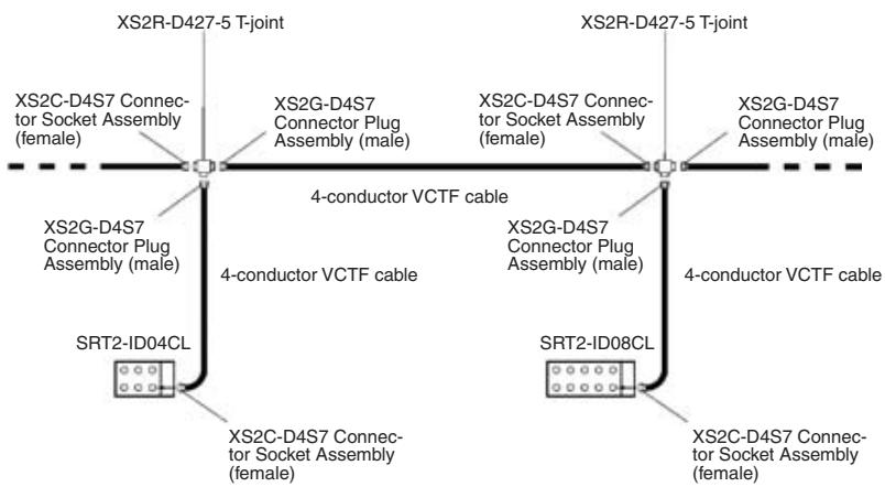
Note Tighten the connector securely by hand to a torque of 0.39 to 0.49N· m . If the connector is not tightened securely, the connector will be loosened or cannot maintain the enclosure rating. Do not tighten the connector with tools such as pliers, or otherwise the connector may be broken.
I/O Power Supply Wiring
Use the following XS2-series Round Water-resistant Connectors to wire I/O power supply.
Connectors
| Type | Model |
| Connectors with Cable (Socket and Plug) | XS2W-D42☐-☐81-☐ |
| Connector with Cable (Female socket on one end) | XS2F-D42☐-☐80-☐ |
| T-joint | XS2R-D427-5 |
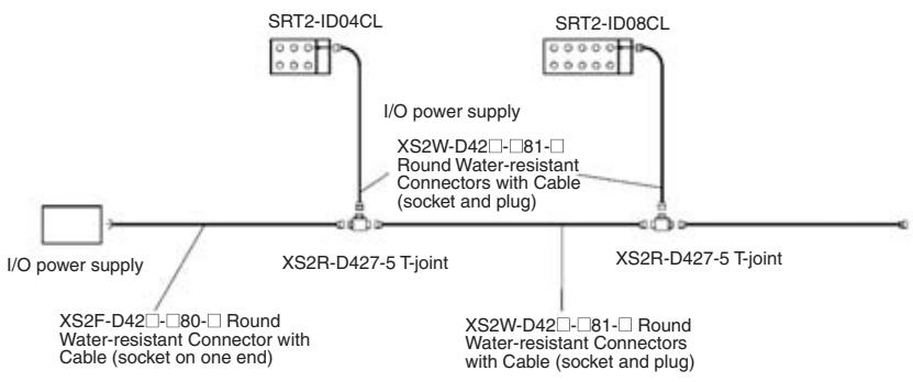
Note
- Tighten the connector securely by hand to a torque of 0.39 to 0.49N· m . If the connector is not tightened securely, the connector will be loosened or cannot maintain the enclosure rating. Do not tighten the connector with tools such as pliers, or otherwise the connector may be broken.
- A single I/O power supply can be used for input and output. Input devices may, however, malfunction due to noise generated from output devices. Therefore, it is recommended to use independent I/O power supplies.
- Commercial available VCTF cable can be used for I/O power cable, provided that the specifications of the VCTF cable, such as the permissible current and voltage drop, satisfy the conditions.
I/O Wiring
Used the following XS2-series Round Water-resistant Connectors to wire I/O.
Connectors
| Type | Model |
| Connector with Cable (Male plug on one end) | XS2H-D421-□80-A |
| Connectors with Cable (Socket and plug) | XS2W-D42□-□81-A |
| Connector Plug Assembly (Male) (Crimp terminals/Solder terminals) | XS2R-D4□□ |
A sensor with a relay connector can directly connect to the Unit.
When connecting a device, check the pin arrangement of the device with the datasheet.
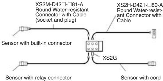
Refer to the Sensor General Catalog for sensors with connectors and Round Water-resistant Connectors (sensor I/O connectors) in detail.
Note
- Tighten the connector securely by hand to a torque of 0.39 to 0.49N· m . If the connector is not tightened securely, the connector will be loosened or cannot maintain the enclosure rating. Do not tighten the connector with tools such as pliers, or otherwise the connector may be broken.
- Attach the XS2Z-12 Water-resistant Cover or XS2Z-15 Dust Cover to unused connectors.
XS2Z-12 Water-resistant Cover

XS2Z-15 Dust Cover
The connector with the Water-resistant Cover will be of IP67 construction. Attach the Water-resistant Cover to the connector and tighten the Water-resistant Cover securely by hand to a torque of 0.39 to 0.49N· m
Press the Dust Cover deeply enough to the Dust Cover. The Dust Cover is not of IP67 construction.
Note
- Check that the junction of the contact block and cover is free of external force imposed, or otherwise the IP67 enclosure rating will be lost.
- Water-resistant Terminals used as Slaves are of IP67 construction. Do not attempt to use the Water-resistant Terminals for applications where the Water-resistant Terminals are always underwater.
- The Unit is a plastic resin mold product. Do not tread on the Unit or put objects on the Unit.
OMRON's 2-wired Proximity Sensors with relay connectors are classified into M1GJ models, which have the IEC pin arrangement, and M1J models, which have the OMRON pin arrangement. The following Water-resistant Terminals are compatible with these different pin arrangements.
| 2-wired sensor (with relay connector) | Compatible Water-resistant Terminals |
| IEC pin arrangement (M1GJ model) | SRT2-ID04CL-1 SRT2-ID08CL-1 |
| OMRON pin arrangement (M1J model) | SRT2-ID04CL SRT2-ID08CL |
5-4-2 SRT2-OD□□CL (-1) Water-resistant Terminals with 4 or 8 Transistor Outputs
Specifications
The following tables show the ratings and input specifications for the SRT2-OD□□CL (-1).
Ratings
| Item | Specification |
| Models | SRT2-OD04CL, SRT2-OD04CL-1, SRT2-OD08CL, SRT2-OD08CL-1 |
| I/O points | SRT2-OD04CL: 4 output points (NPN)SRT2-OD04CL-1: 4 output points (PNP)SRT2-OD08CL: 8 output points (NPN)SRT2-OD08CL-1: 8 output points (PNP) |
| Connection | CommunicationsXS2C-D4S7: Connector Socket Assembly (female)(Crimp terminals/Solder terminals)OutputsXS2G-D4☐☐: Connector Plug Assembly (male)(Crimp terminals/Solder terminals)XS2H-D421☐☐☐: Connector with cable (male plug on one end)XS2W-D42☐-☐☐☐: Connectors with cable (Socket/Plug on both ends)I/O powerXS2C-D4☐☐: Connector Socket Assembly (female)(Crimp terminals/Solder terminals)XS2F-D42☐-☐80-A: Connector with cable(female socket on one end) |
| Power supply type | Multiple power supplies |
| Communications power supply voltage | 14 to 26.4 V DC(Power can be supplied from the communications cable) |
| I/O power supply voltage | 20.4 to 26.4 V DC (24 V DC +10%/_-15%) |
| I/O power supply current | 2.4 A max. |
| Current consumption(See note.) | Communications power: 50 mA max. at 24 V DC |
| Noise immunity | 1.5 kVp-p with a pulse width of 0.1 to 1 μs and a rise time of 1 ns (tested with impulse noise simulator) |
| Vibration resistance | 10 to 150 Hz, 0.7-mm double amplitude or 50 m/s2 |
| Shock resistance | 150 m/s2 |
| Dielectric strength | 500 V AC (between insulated circuits) |
| Insulation resistance | 20 MΩ min. (between insulated circuits) |
| Ambient temperature | Operating: -10 to 55°C (with no icing or condensation) Storage: -25 to 65°C (with no icing or condensation) |
| Ambient humidity | Operating: 25% to 85% (with no condensation) Storage: 25% to 85% (with no condensation) |
| Operating environment | No corrosive gases |
| Enclosure rating | IP67 |
| Mounting method | M5 screws |
| Terminal strength | 100N |
| Node number settings | The node number is set on a rotary switch. (Set the node number before turning ON the Slave.) |
| Weight | SRT2-OD04CL (-1): 180 g max. SRT2-OD08CL (-1): 240 g max. |
Note This is the current consumption when all the maximum simultaneous output points are ON, excluding the current consumption of external loads.
Output Specifications
| Item | Specifications |
| Output current | OD04CL (-1): 0.3 A/point 1.2 A/common OD08CL (-1): 0.3 A/point 2.4 A/common |
| Residual voltage | 1.2 V max. |
| Leakage current | 0.1 mA max. |
| ON delay time | 0.5 ms max. |
| OFF delay time | 1.5 ms max. |
| Insulation method | Photocoupler |
| Output indicator | LED (yellow) |
| Number of circuits | OD04CL (-1): 4 points/single common circuit OD08CL (-1): 8 points/single common circuit |
Slave Components
The following diagram shows the main components of the SRT2-OD□□CL (-□) Water-resistant Terminals with Transistor Outputs. The functions of these components are described below.
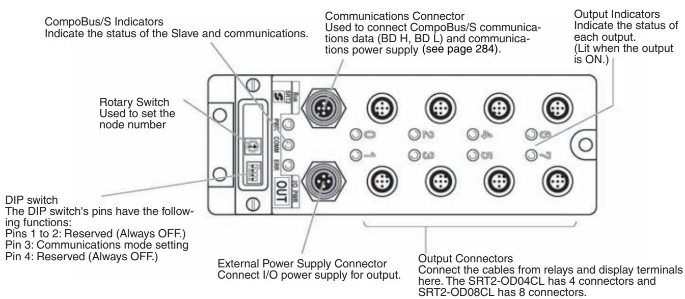
Indicators
The following table shows the meaning of the indicators.
| Indicator | Name | Status | Meaning |
| PWR (green) | Power | ON | The communications power supply is ON. |
| OFF | The communications power supply is OFF. | ||
| COMM (yellow) | Commu- nications | ON | Normal communications. |
| OFF | A communications error has occurred or the Unit is in standby status. | ||
| ERR (red) | Commu- nications error | ON | A communications error has occurred. |
| OFF | Normal communications or the Unit is in standby status. | ||
| OUT0 to 3 (4 outputs) OUT0 to 7 (8 outputs) (yellow) | Output | ON | The corresponding input is ON. |
| OFF | The corresponding input is OFF or the Unit is in standby status. |
Switch Settings
The rotary switch and the DIP switch are located under the transparent cover.
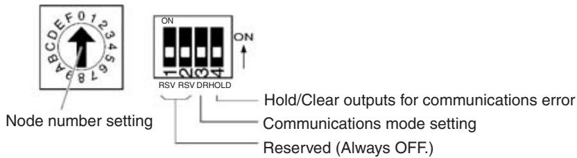
Note 1. Always turn OFF the Slave before changing switch settings.
2. Always set all the reserved pins to OFF, or otherwise the Unit may not operate normally.
Node Number Settings
Set the node number in hexadecimal with the rotary switch as shown in the following table.
| Node number | Setting (Hex) | Node number | Setting (Hex) |
| 0 | 0 | 8 | 8 |
| 1 | 1 | 9 | 9 |
| 2 | 2 | 10 | A |
| 3 | 3 | 11 | B |
| 4 | 4 | 12 | C |
| 5 | 5 | 13 | D |
| 6 | 6 | 14 | E |
| 7 | 7 | 15 | F |
Note The possible range of node numbers varies with the type of Master and settings in the Master. Refer to 2-1 Communications Specifications for details.
Communications Mode Settings
The following communications modes are set with pin 3 of the DIP switch as shown below.
| Pin 3 | Comunica-tions mode | Communica-tions distance | Communica-tions baud rate | Communica-tions cycle time |
| OFF | High-speed Com-munications Mode | 100 m max. | 750 kbps | 0.5 or 0.8 ms |
| ON | Long-distance Communications Mode | 500 m max. | 93.75 kbps | 4.0 or 6.0 ms |
Note Make sure that the communications mode of the Slave is the same as that of the Master Unit. If the communications modes are not the same, normal communications with the Master Unit will not be possible. The operating status of the Slave can be verified with LED indicators. Refer to 6-5-1 Indicators.
Hold/Clear Outputs for Communications Error
Pin 4 is used to set the output data status when a communications error occurs, as shown in the following table.
| Pin 4 (HOLD) | Output setting |
| OFF | Clear output status. |
| ON | Maintain output status. |
Internal Circuits
SRT2-OD04CL and SRT2-OD08CL
The following diagram shows the internal circuits for the SRT2-OD04CL and SRT2-OD08CL.
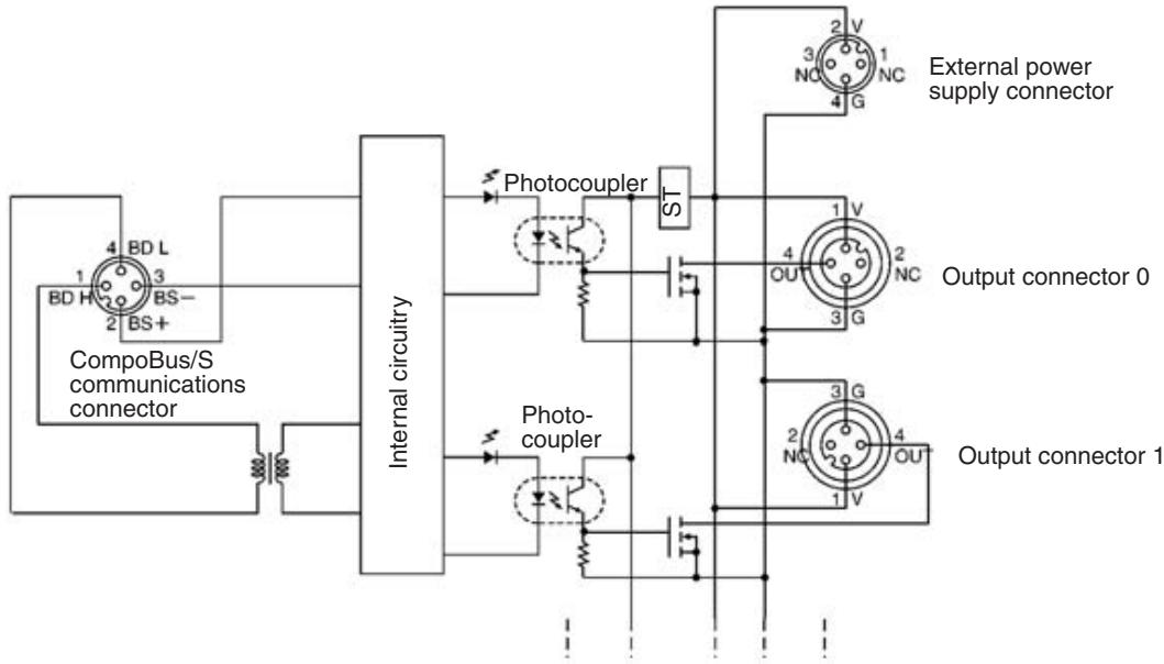
SRT2-OD04CL-1 and SRT2-OD08CL-1
The following diagram shows the internal circuits for the SRT2-OD04CL-1 and SRT2-OD08CL-1.
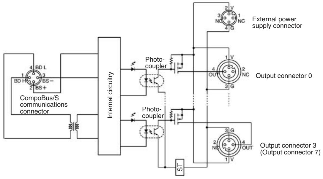
Wiring
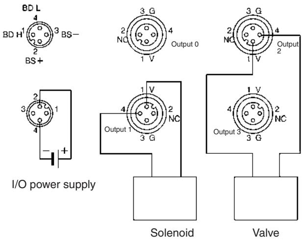
SRT2-OD04CL
SRT2-OD04CL-1
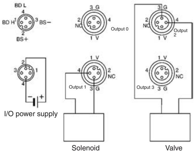
Note The V terminals are all connected internally, as are the G terminals. Output connectors G and V are available to external power supply, provided that the total current flow through these connectors is less than 2.0 A when output power supply is provided to the external power supply connector. Connect external power supply if the total current flow is 2.0 A or more.
SRT2-OD08CL
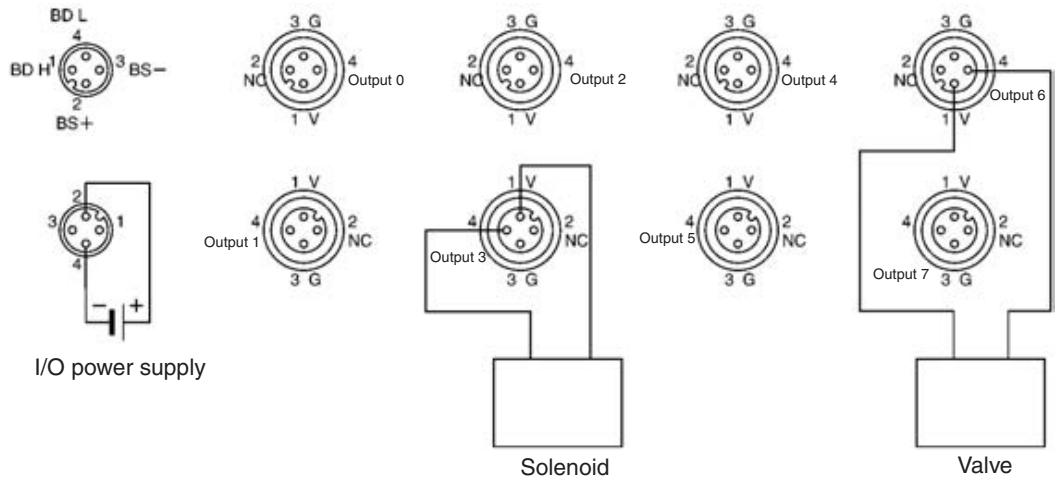
SRT2-OD08CL-1
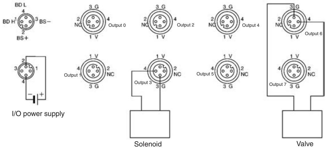
Note The V terminals are all connected internally, as are the G terminals. Output connectors G and V are available to external power supply, provided that the total current flow through these connectors is less than 2.4 A when output power supply is provided to the external power supply connector. Connect external power supply if the total current flow is 2.4 A or more.
Dimensions
SRT2-OD04CL, SRT2-OD04CL-1
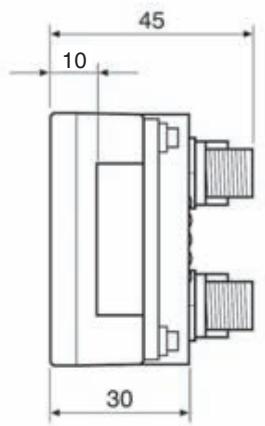
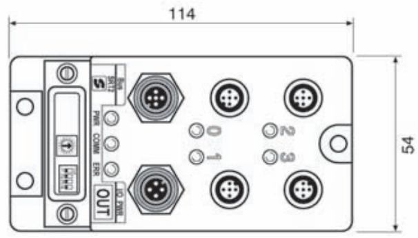
Mounting dimensions
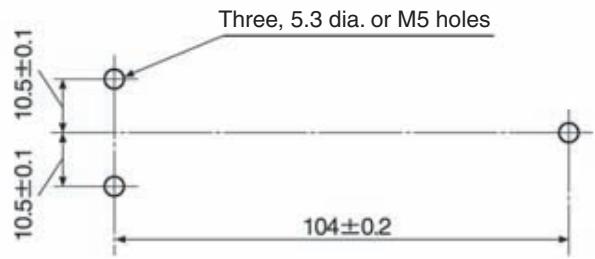
(Unit: mm)
SRT2-OD08CL, SRT2-OD08CL-1
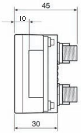
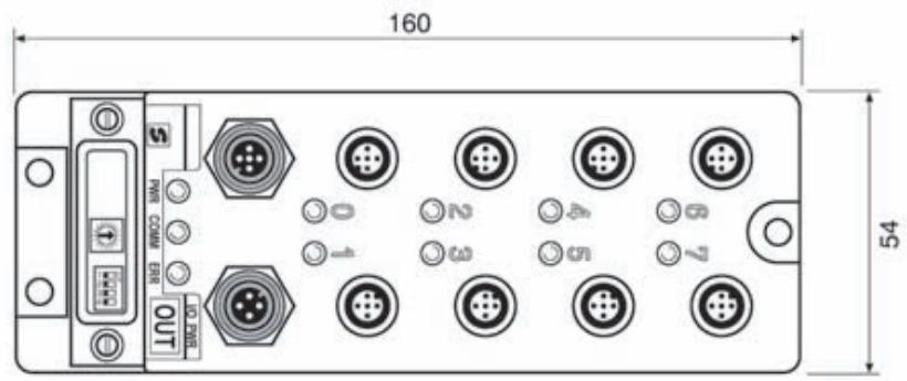
Mounting dimensions
(Unit: mm)
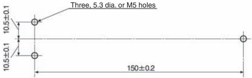
Note For details on the communications cable, I/O power supply, and I/O wiring, refer to Communications Cable, I/O Power Supply, and I/O Wiring on page 275 under 5-4-1 SRT2-ID□□CL (-1) Water-resistant Terminals with 4 or 8 Transistor Inputs.
5-4-3 Shielded Connector Wiring and Assembly
Connect external I/O power supply and I/O Units to Water-resistant Terminals through Shielded Connector (round Water-resistant connectors). Water-resistant Terminals has a male plug for the external power supply connector and a female socket for the I/O connector. Select ones from the following XS2-series Round Water-resistant Connectors according to the I/O power supply method or the I/O Unit.
- Connectors for External Power Supply
| Connector type | Model |
| Round Water-resistant Connectors with Cable (socket and plug) | XS2W-D42☐-☐81☐ |
| Round Water-resistant Connector with Cable (socket on one end) | XS2F-D42☐-☐80☐ |
| Connector Socket Assembly (female) (Crimp terminals/Solder terminals) | XS2C-D4☐☐ |
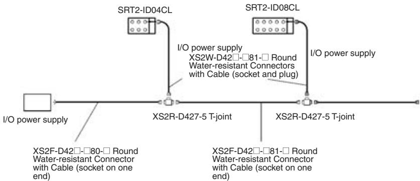
I/O Connectors
| Connector type | Model |
| Connector with cable (male plug on one end) | XS2H-D421-□80-A |
| Round Water-resistant Connectors with Cable (socket and plug) | XS2W-D42□-□81-A |
| Connector Socket Assembly (female) (Crimp terminals/Sol- der terminals) | XS2G-D4□ |
The sensor with a relay connector can directly connect to the Unit.
When connecting a device, check the pin arrangement of the device with the datasheet.
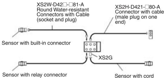
Press the cable connector to the terminal connector until the cable connector comes in contact with the bottom end of the cable connector. Tighten the connector screws to the specified tightening torque (0.39 to 0.49 N·m).
Caution
Tighten the connector securely by hand to a torque of 0.39 to 0.49 N·m. If the connector is not tightened securely, the connector will be loosened or cannot keep the enclosure rating. Do not tighten the connector with tools such as pliers, or otherwise the connector may be broken.
Caution
Connectors vary in direction. Check the direction before inserting the connector.
Caution
Do not pull or bend the cable. Provide some margin when laying the cable. Check that the cable is free of heavy objects, or otherwise the cable may be broken.
| Note | 1. A single I/O power supply can be used for input and output. Input devices may, however, malfunction due to noise generated from output devices. Therefore, it is recommended to use independent I/O power supplies. 2. Refer to the Sensor Catalog for sensors with connectors and Round Water-resistant Connectors (sensor I/O connectors) in detail. |
| Round Communications Connector to Water-resistant Terminals or T-joints | The communications cable connects to Water-resistant Terminals or T-joints through a round communications connector. Press the cable connector to the terminal or joint connector until the cable connector comes in contact with the bottom end of the cable connector. Tighten the connector screws to the specified tightening torque (0.39 to 0.49 N·m). |
| Caution | The connector direction varies with the type of Connector Terminal. Check the connecting direction before inserting the connector. |
| Caution | Do not pull or bend the communications cable. Provide some margin when laying the communications cable. Check that the communications cable is free of heavy objects, or otherwise the cable may be broken. |
| Shielded Terminator Connection | The Shielded Terminator has round communications connector (or shielded connector). Connect the Shield Terminator to T-joints or the round communications connectors of communications cable. Press the cable connector to the terminal or joint connector until the cable connector comes in contact with the bottom end of the cable connector. Tighten the connector screws to the specified tightening torque (0.39 to 0.49 N·m). |
| Caution | The connector direction varies with the type of Connector Terminal. Check the connecting direction before inserting the connector. |
5-5 Sensor Terminals
5-5-1 SRT□-□D08S Sensor Terminals with 8 Transistor Inputs or 4 Transistor Inputs and 4 Transistor Outputs
Specifications
The following tables show the ratings and I/O specifications for the SRT□-D08S
Ratings
| Item | Specification |
| Models | SRT1-ID08S SRT1-ND08S SRT2-ID08S SRT2-ND08S |
| I/O points | SRT□-ID08S: 8 input points SRT□-ND08S: 4 input and 4 output points |
| Communications mode | SRT1-□D08S: High-speed Communications Mode SRT2-□D08S: High-speed Communications Mode or Long-distance Communications Mode |
| Power supply type | Network power supply |
| Communications power supply voltage | 14 to 26.4 V DC (see note 1) (Power can be supplied from the communications cable) |
| Current consumption (see note 2) | Communications: 50 mA max. at 24 V DC |
| Noise immunity | ±1.5 kVp-p with a pulse width of 0.1 to 1 μs and a rise time of 1 ns (via impulse noise simulator) |
| Vibration resistance | 10 to 55 Hz, 1.0-mm double amplitude |
| Shock resistance | 200 m/s² |
| Dielectric strength | 500 V AC (between insulated circuits) |
| Ambient temperature | Operating: 0 to 55°C Storage: -20 to 65°C |
| Ambient humidity | Operating: 35% to 85% (with no condensation) Storage: 25% to 85% (with no condensation) |
| Operating environment | No corrosive gases |
| Mounting method | M4 screws or 35-mm DIN track mounting |
| Mounting strength | 50 N Track direction: 10 N • m |
| Terminal strength | Pulling: 50 N Tightening: 0.6 to 1.18 N • m |
| Node number settings | The node number is set on a DIP switch. (Set the node number before turning ON the Slave.) |
| Weight | SRT□-ID08S: 100 g max. SRT□-ND08S: 80 g max. |
Note
- Maintain a voltage of 20.4 to 26.4 V DC when using a 2-wired Proximity Sensor.
- This is the current consumption when all contacts are OFF, not including the current consumption of the sensors. Be sure to take the sensor's current into account when supplying power from a CompoBus/S cable. The maximum current consumption of the Sensor Terminal can be calculated from the following equation:
Max. current consumption = current consumption of the Sensor Terminal + ({input current + output current + sensor's current consumption} × the number of sensors being used)
The total current consumption of the sensors must be less than 500mA .
Input Specifications
| Item | Specification |
| ON voltage | 12 V DC min. (between each input terminal and VCC, the external sensor power supply) |
| OFF voltage | 4 V DC max. (between each input terminal and VCC, the external sensor power supply) |
| OFF current | 1 V max. |
| Input current | 10 mA max./point |
| ON delay time | 1 ms max. |
| OFF delay time | 1.5 ms max. |
| Insulation resistance | 20 MΩ min. at 250 V DC (between insulated circuits) |
| Insulation method | Photocoupler |
Output Specifications
| Item | Specification |
| Rated output current | 20 mA max. |
| Residual voltage | 1 V max. (between each output terminal and VCC, the external sensor power supply) |
| Leakage current | 0.1 mA max. (between each output terminal and VCC, the external sensor power supply) |
| ON delay time | 1.0 ms max. |
| OFF delay time | 1.5 ms max. |
| Insulation resistance | 20 MΩ min. at 250 V DC |
| Insulation method | Photocoupler |
Slave Components
The following diagram shows the main components of the Sensor Terminals. The functions of these components are described below.
CompoBus/S Indicators
Indicate the status of the Slave and communications.
DIP Switch
The DIP switch's pins have the following functions:
Pins 1 to 4: Node number setting
Pin 5: Communications mode setting (SRT2 Series) or
Reserved (Always OFF) (SRT1 Series)
Pin 6: Hold/clear outputs for communications error
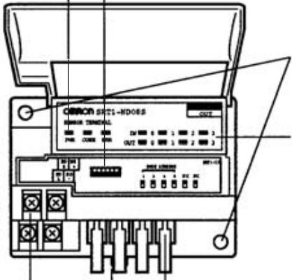
Mounting Screw Holes
Used when screwing the Unit to a control panel.
I/O Indicators
Indicate the status of each contact.
(Lit when the input or output is ON.)
The SRT□-ID08S has 8 input indicators and
the SRT□-ND08S has 4 input indicators and
4 output indicators.
Sensor Terminal I/O Connectors
Connect the cables from the sensors here.
DIN Track Mounting Hook
Used when mounting the Unit to a DIN track.
CompoBus/S Terminal Block
Connect the CompoBus/S communications cable and the com
munications power supply (including the I/O power supply).
Indicators
The following table shows the meaning of the indicators.
| Indicator | Status | Meaning |
| PWR (green) | ON | The communications power supply is ON. |
| OFF | The communications power supply is OFF. | |
| COMM (yellow) | ON | Normal communications |
| OFF | A communications error has occurred or the Unit is in standby status. | |
| ERR (red) | ON | A communications error has occurred. |
| OFF | Normal communications or the Unit is in standby status. | |
| INO to 3 (4 inputs/outputs) | ON | The corresponding input is ON. |
| INO to 7 (8 inputs) (yellow) | OFF | The corresponding input is OFF or the Unit is in standby status. |
| OUT0 to 3 (4 inputs/outputs) (yellow) | ON | The corresponding output is ON. |
| OFF | The corresponding output is OFF or the Unit is in standby status. |
DIP Switch
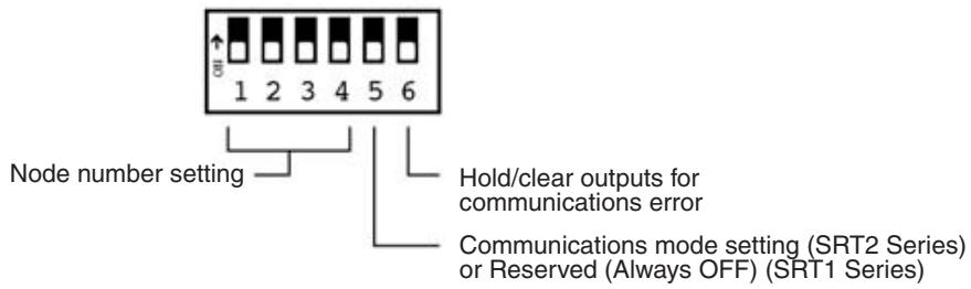
Note Always turn OFF the Slave before changing DIP switch settings.
Node Number Settings
Set the node number with pins 1 through 4, as shown in the following table.
| Node number | Pin 4 (8) | Pin 3 (4) | Pin 2 (2) | Pin 1 (1) |
| 0 | OFF | OFF | OFF | OFF |
| 1 | OFF | OFF | OFF | ON |
| 2 | OFF | OFF | ON | OFF |
| 3 | OFF | OFF | ON | ON |
| 4 | OFF | ON | OFF | OFF |
| 5 | OFF | ON | OFF | ON |
| 6 | OFF | ON | ON | OFF |
| 7 | OFF | ON | ON | ON |
| 8 | ON | OFF | OFF | OFF |
| 9 | ON | OFF | OFF | ON |
| 10 | ON | OFF | ON | OFF |
| 11 | ON | OFF | ON | ON |
| 12 | ON | ON | OFF | OFF |
| 13 | ON | ON | OFF | ON |
| 14 | ON | ON | ON | OFF |
| 15 | ON | ON | ON | ON |
Note The actual node number setting range depends on the type of PLC in which the Master is mounted as well as the Master's settings. Refer to 2-1 Communications Specifications for details.
Communications Mode Settings (SRT2 Series Only)
The following communications modes are set with pin 5 as shown below.
| Pin 5 | Communications mode | Communications distance | Communications baud rate | Communications cycle time |
| OFF | High-speed Communications Mode | 100 m max. | 750 kbps | 0.5 or 0.8 ms |
| ON | Long-distance Communications Mode | 500 m max. | 93.75 kbps | 4.0 or 6.0 ms |
The communications mode settings using pin 5 only apply to the SRT2-series Slaves and cannot be used with the SRT1-series Slaves, which operate in High-speed Communications Mode at all times.
Note Make sure that the communications mode of the Slave is the same as that of the Master Unit. If the communications modes are not the same, normal communications with the Master Unit will not be possible. The operating status of the Slave can be verified with LED indicators. Refer to 6-5-1 Indicators.
Hold/Clear Outputs for Communications Error
Pin 6 is used to set the output data status when a communications error occurs, as shown in the following table.
| Pin 6 | Output setting |
| OFF | Clear output status. |
| ON | Maintain output status. |
Sensor Compatibility
Use the following flowchart to determine whether a sensor is compatible with the Sensor Terminal.
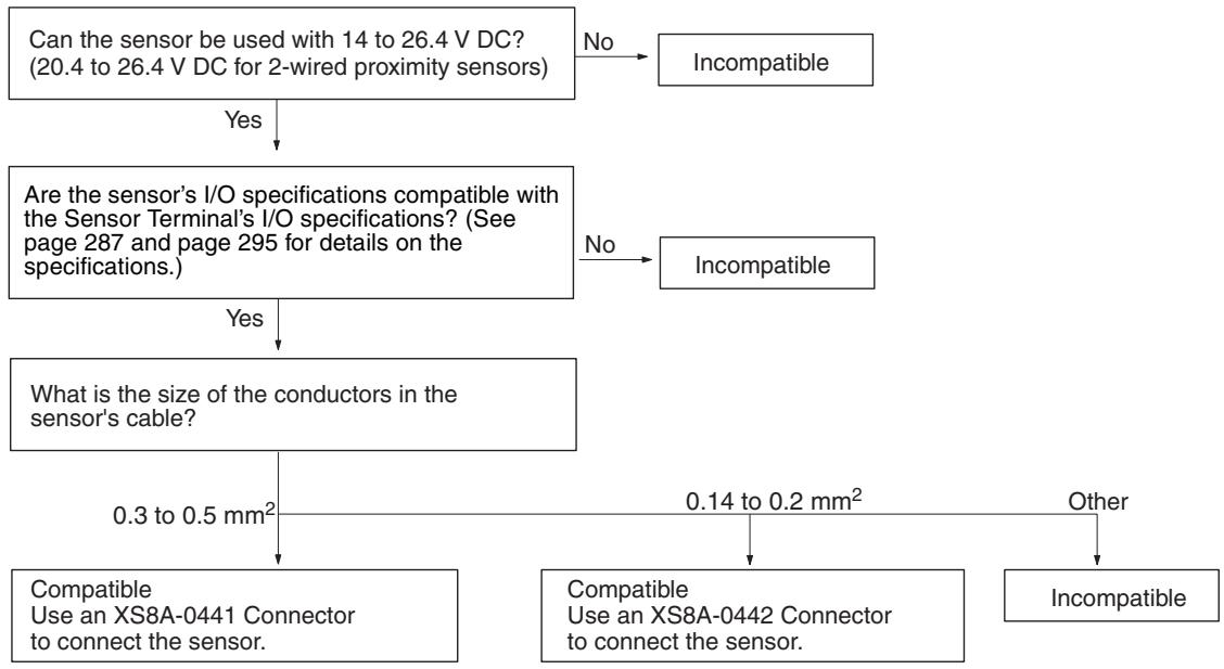
Note The XS8A-0441 and XS8A-0442 Connectors are not provided with the Unit. The Connectors must be ordered separately.
Internal Circuits
The following diagram shows the internal circuits for the SRT□-ID08S (8 inputs).
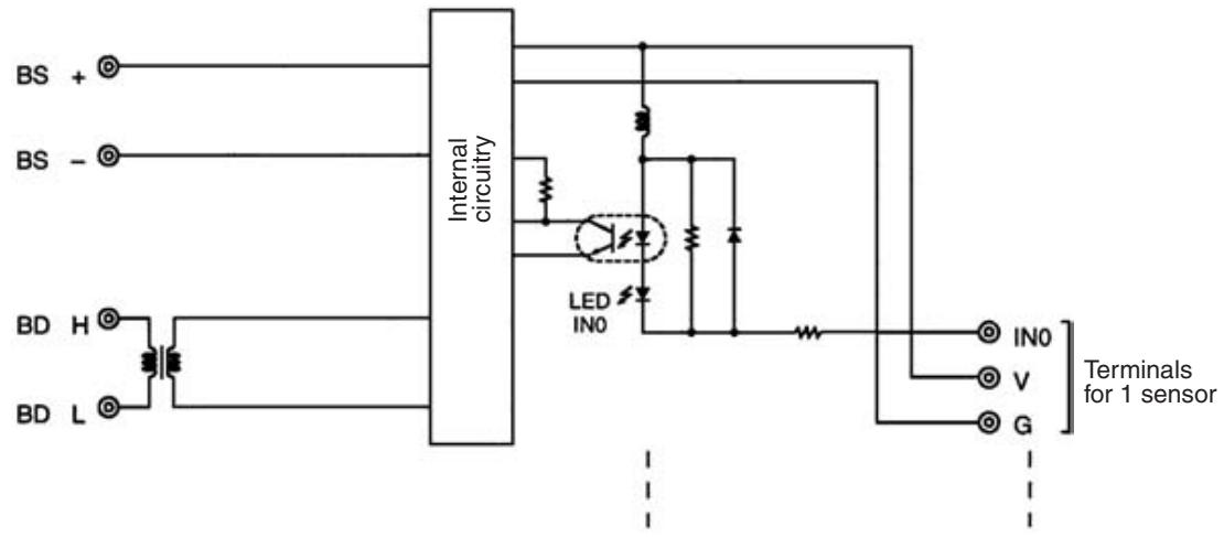
The following diagram shows the internal circuits for the SRT□-ND08S (4 inputs and 4 outputs).
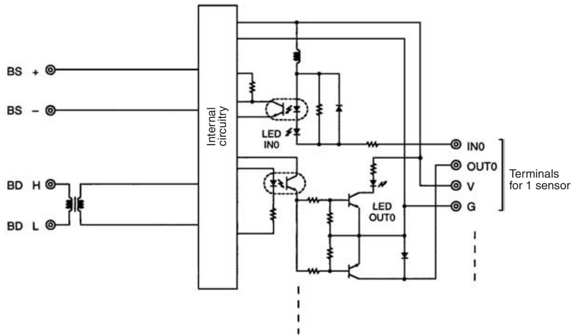
Terminal Arrangement and Wiring
The following diagram shows the terminal arrangement and wiring for the SRT□-ID08S (8 inputs).

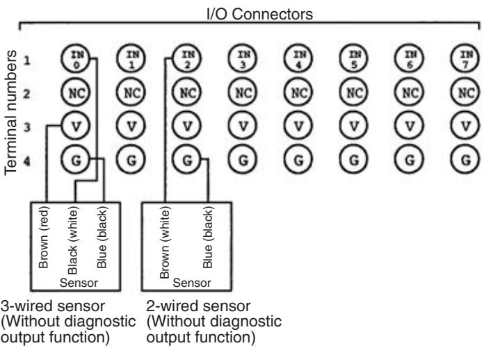
Note In accordance with the changes in the standards for photoelectric sensors and proximity sensors, wire colors have been changed. Colors in parentheses are the old wire colors.
The following table shows the terminal arrangement and wiring for the Sensor Terminal's I/O Connector.
| Terminal number | Function |
| 1 | IN (Input) |
| 2 | NC (Not used.) |
| 3 | VCC(V) (External sensor power supply, + terminal) |
| 4 | GND(G) (External sensor power supply, - terminal) |
The following diagram shows the terminal arrangement and wiring for the SRT□-ND08S (4 inputs and 4 outputs).
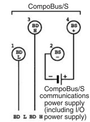
CompoBus/S communications
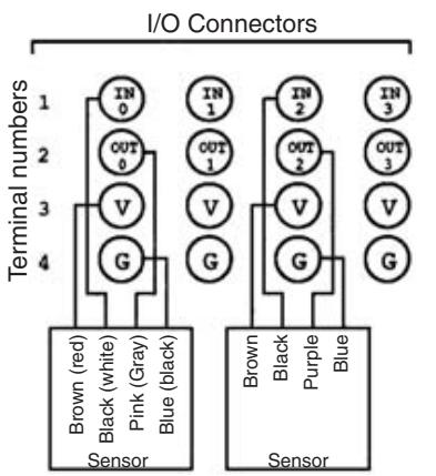
Sensor with teaching function
Sensor with external diagnostic function
Sensor with bank-switching function
Note In accordance with the changes in the standards for photoelectric sensors and proximity sensors, wire colors have been changed. Colors in parentheses are the old wire colors.
The following table shows the terminal arrangement and wiring for the Sensor Terminal's I/O Connector.
| Terminal number | Function |
| 1 | IN (Input) |
| 2 | OUT (Output) |
| 3 | VCC(V) (External sensor power supply, + terminal) |
| 4 | GND(G) (External sensor power supply, - terminal) |
SRT□-ID08S Dimensions
The following diagram shows the dimensions for the SRT□-ID08S (8 inputs). All dimensions are in mm.
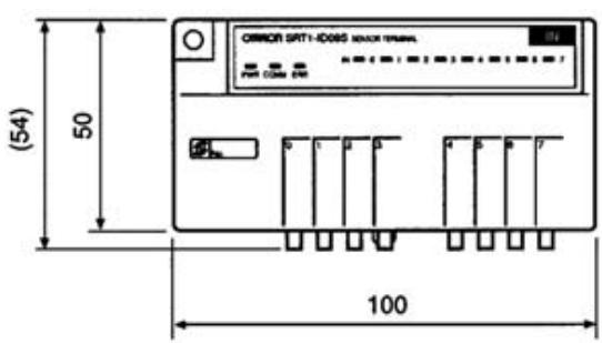
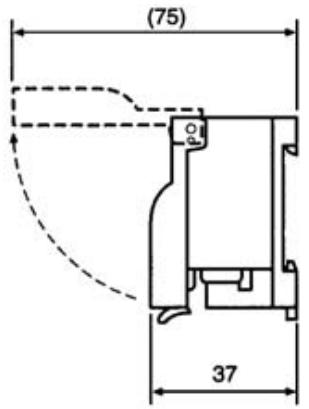
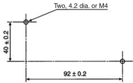
Mounting Holes
SRT□-ND08S Dimensions
The following diagram shows the dimensions for the SRT□-ND08S (4 inputs and 4 outputs). All dimensions are in mm.
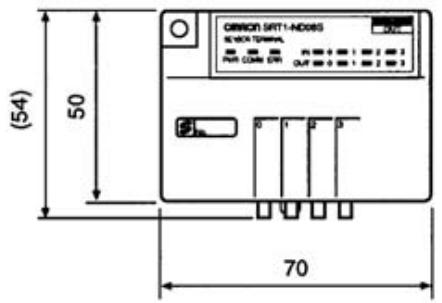
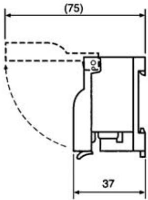
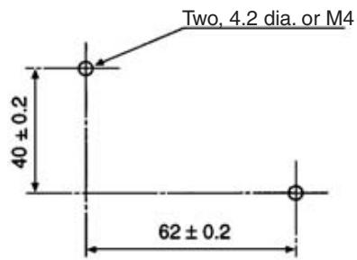
Mounting Holes
5-5-2 SRT□-OD08S Sensor Terminal with 8 Transistor Outputs
Specifications
The following tables show the ratings and output specifications for the SRT□-OD08S.
Ratings
| Item | Specification |
| Models | SRT1-OD08S SRT2-OD08S |
| Output points | 8 points |
| Communications mode | SRT1-OD08S: High-speed Communications Mode SRT2-OD08S: High-speed Communications Mode or Long-distance Communications Mode |
| Power supply type | Local power supply |
| Communications power supply voltage (including I/O power supply) | 20.4 to 26.4 V DC (24 V DC +10%/_-15%) (Power can be supplied from the communications cable) |
| I/O power supply current | 2.4 A max. |
| Current consumption (See note.) | 50 mA max. at 24 V DC |
| Noise immunity | ±1.5 kVp-p a pulse width of 0.1 to 1 μs and a rise time of 1 ns (via impulse noise simulator) |
| Vibration resistance | 10 to 55 Hz, 1.5 mm double amplitude |
| Shock resistance | Malfunction: 200 m/s² (approx. 20G) Destruction: 300 m/s² (approx. 30G) |
| Dielectric strength | 500 V AC (between insulated circuits) |
| Ambient temperature | Operating: 0 to 55°C Storage: -20 to 65°C (with no icing or condensation) |
| Ambient humidity | Operating: 35% to 85% (with no condensation) Storage: 25% to 85% (with no condensation) |
| Operating environment | No corrosive gases |
| Mounting method | M4 screws or 35-mm DIN track mounting |
| Mounting strength | 50 N Track direction: 10 N·m |
| Terminal strength | Pulling: 50 N Tightening torque: 0.6 to 1.18 N·m Excluding strength of connector lock |
| Node number settings | The node number is set on a DIP switch. (Set the node number before turning ON the Slave.) |
| Weight | 100 g max. |
Note The current consumption is the value when all points are OFF, excluding the current consumption of the external sensor connected to the Sensor Terminal inputs and the current consumption of the load connected to the Sensor Terminal outputs.
Output Specifications
| Item | Specification |
| Output current | 0.3 A max./point |
| Residual voltage | 0.6 V max. |
| Leakage current | 0.1 mA max. |
| ON delay time | 0.5 ms max. |
| OFF delay time | 1.5 ms max. |
| Insulation method | Photocoupler |
| Output indicators | LED (yellow) |
Slave Components
The following diagram shows the main components of the SRT□-OD08S Sensor Terminals. The functions of these components are described below.
CompoBus/S Indicators
Indicate the status of the Slave and communications.
DIP Switch
The DIP switch's pins have the following functions:
Pins 1 to 4: Node number setting
Pin 5: Communications mode setting (SRT2 Series)
or Reserved (Always OFF) (SRT1 Series)
Pin 6: Hold/Clear outputs for communications error
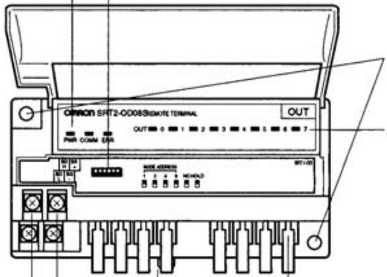
Mounting Screw Holes
Used when screwing the
Unit to a control panel.
Output Indicators
Indicate the output status
of each contact. (Lit when
the output is ON.)
Output Connector for Remote Terminal
Connect the cable connector attached to output wires
leading to output devices such as solenoids, valves, and
lamps
Cable connectors XS8A-0441 (compatible wire size: 0.3 to
0.5mm^2 and XS8A-0442 (compatible wire size: 0.14 to
0.2mm^2) are sold separately.
DIN Track Mounting Hook
Used when mounting the Unit to a DIN track.
Power Supply Terminal Block
Used to connect the CompoBus/S communications power
supply (including I/O power supply).
Power supply from the special Flat Cable is not possible,
so a separate power supply must be connected.
CompoBus/S Terminal Block
Used to connect the CompoBus/S communications cable.
Indicators
The following table shows the meaning of the indicators.
| Indicator | Status | Meaning |
| PWR (green) | ON | The external power supply is ON. |
| OFF | The external power supply is OFF. | |
| COMM (yellow) | ON | Normal communications |
| OFF | A communications error has occurred or the Unit is in standby status. | |
| ERR (red) | ON | A communications error has occurred. |
| OFF | Normal communications or the Unit is in standby status. | |
| OUT 0 to 7 (yellow) | ON | The corresponding output is ON. |
| OFF | The corresponding output is OFF or the Unit is in standby status. |
DIP Switch
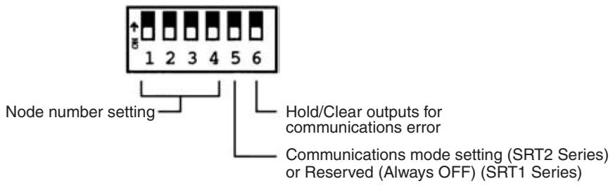
Note 1. Always turn OFF the Slave before changing DIP switch settings.
2. In the SRT1 Series, pin 5 must always be left OFF. Otherwise, the Unit may not function correctly.
Hold/Clear Outputs for Communications Error
Pin 6 is used to set the output data status when a communications error occurs, as shown in the following table.
| Pin 6 (HOLD) | Output setting |
| OFF | Clear output status. |
| ON | Maintain output status. |
Communications Mode Settings (SRT2 Series Only)
The following communications modes are set with pin 5.
| Pin 5 | Communications mode | Communications distance | Communications baud rate | Communications cycle time |
| OFF | High-speed Communications Mode | 100 m max. | 750 kbps | 0.5 or 0.8 ms |
| ON | Long-distance Communications Mode | 500 m max. | 93.75 kbps | 4.0 or 6.0 ms |
The communications mode settings using pin 5 only apply to the SRT2-series Slaves and cannot be used with the SRT1-series Slaves, which operate in High-speed Communications Mode at all times.
Note Make sure that the communications mode of the Slave is the same as that of the Master Unit. If the communications modes are not the same, normal communications with the Master Unit will not be possible. The operating status of the Slave can be verified with LED indicators. Refer to 6-5-1 Indicators for details.
Node Number Settings
Set the node number with pins 1 through 4, as shown in the following table.
| Node number | Pin 4 (8) | Pin 3 (4) | Pin 2 (2) | Pin 1 (1) |
| 0 | OFF | OFF | OFF | OFF |
| 1 | OFF | OFF | OFF | ON |
| 2 | OFF | OFF | ON | OFF |
| 3 | OFF | OFF | ON | ON |
| 4 | OFF | ON | OFF | OFF |
| 5 | OFF | ON | OFF | ON |
| 6 | OFF | ON | ON | OFF |
| 7 | OFF | ON | ON | ON |
| 8 | ON | OFF | OFF | OFF |
| 9 | ON | OFF | OFF | ON |
| 10 | ON | OFF | ON | OFF |
| 11 | ON | OFF | ON | ON |
| 12 | ON | ON | OFF | OFF |
| 13 | ON | ON | OFF | ON |
| 14 | ON | ON | ON | OFF |
| 15 | ON | ON | ON | ON |
Compatible External Devices and Cables
Note The actual node number setting range depends on the type of PLC in which the Master is mounted as well as the Master's settings. Refer to 2-1 Communications Specifications for details.
Remote Terminals with Connector Output Transistors use the XS8A-0441 and XS8A-0442 Connectors (sold separately) to connect to external devices. Use the following flowchart to check the compatibility of external devices and cables. Refer to 3-4-3 Cable Connector Wiring and Assembly for details on the assembly, wiring, and installation of cable connectors.
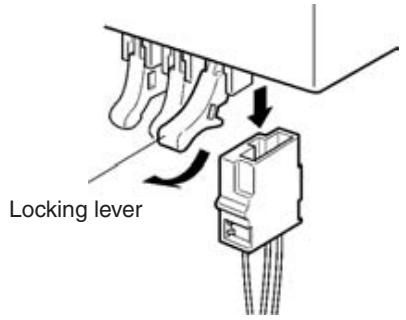
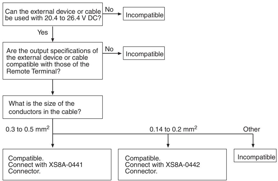
Note The XS8A-0441 and XS8A-0442 Connectors are not provided with the Unit. The Connectors must be ordered separately.
Internal Circuits

Terminal Arrangement and Wiring
internal circuitry. The following diagram shows the terminal arrangement and wiring for the SRT-OD08S.
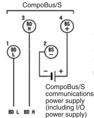

CompoBus/S communications
The following table shows the terminal arrangement and wiring for the Remote Terminal's output connector.
| Terminal number | Function |
| 1 | VCC(V) (External device power supply, + terminal) |
| 2 | GND(G) (External device power supply, - terminal) |
| 3 | OUT(Output) |
| 4 |
Note
- Terminals 3 and 4 are connected internally, so external devices should be connected to terminal 1 (+24 V) and either terminal 3 or 4.
- The BS- and BS+ terminals of the communications power supply (including the I/O power supply) cannot be supplied from a flat cable, so they must be supplied separately.
- When inductive loads such as solenoids and valves are used, either use loads with built-in diodes that absorb the back-electromotive force or connect a diode externally.
SRT-OD08S Dimensions
The following diagram shows the dimensions for the SRT□-OD08S. All dimensions are in mm.
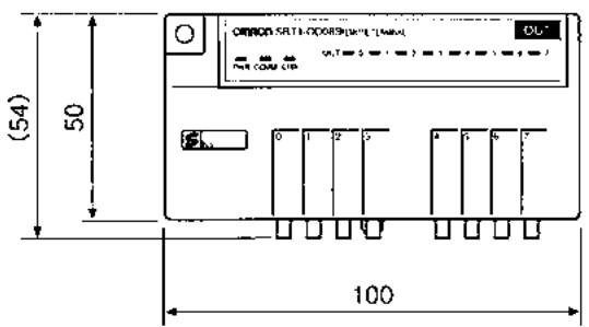
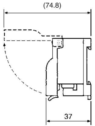
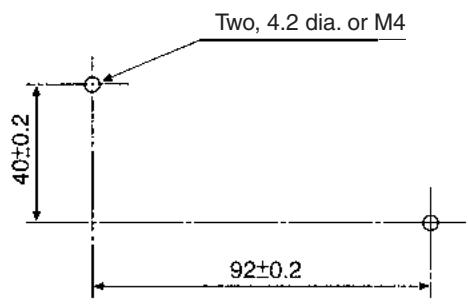
Mounting Holes
5-6 Fiber Amplifier Communications Units
5-6-1 E3X-SRT21 Fiber Amplifier Communications Unit
The Fiber Amplifier Communications Units are Communications Units for E39-TM1 Terminal Block Units or E3X-DA-N-series Digital Fiber Amplifier Units used with Optical Fiber Sensors.
Note In the following description, Digital Fiber Amplifier Units and Terminal Block Units are referred to collectively as Fiber Amplifier Units
The E3X-SRT21 uses CompoBus/S and receives input from the Fiber Amplifier Unit. (Models that function as DeviceNet or RS-422A Slaves are also available.)
Fiber Amplifier Units with connectors can also be used. Data is exchanged with the Fiber Amplifier Units by connecting the Fiber Amplifier Communications Unit to the left side of the multiple Fiber Amplifier Units.
The E3X-MC11 Mobile Console for Fiber Amplifier Units can also be connected.
This section provides an overview of the specifications and functions of the Fiber Amplifier Communications Unit for CompoBus/S. For details, refer to the Fiber Amplifier Communications Unit Operation Manual (Cat. No. Z152)
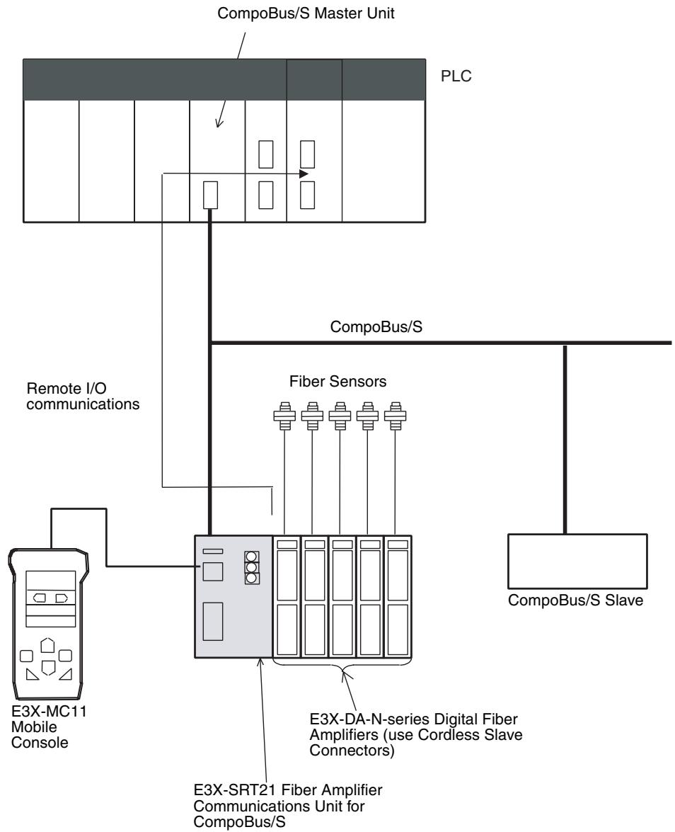
The unit numbers (addresses) are allocated to the Digital Fiber Amplifiers in order starting from the left, as follows:
Amplifiers that use one node: Unit numbers 1 to 6
Amplifiers that use two nodes: Unit numbers 1 to 14
Specifications
| Item | Specification |
| Models | E3X-SRT21 |
| I/O points and I/O con- nection conditions | 6 inputs + 2 status points input from Fiber Amplifier Unit or 14 inputs + 2 status points input from Fiber Amplifier Unit (switch using DIP switch setting) |
| Connection | Inputs: Fiber Amplifier Units Communications: Communications Connector (standard connector pro- vided with Unit) I/O power: Communications Connector (standard connector pro- vided with Unit) |
| Power supply type | Network power supply |
| Communications power supply voltage | 14 to 26.4 V DC (Power can be supplied from the communications cable) |
| I/O power supply voltage | |
| Current consumption (See note.) | Communications power: 30 mA max. at 24 V DC |
| Maximum input delay time | Up to 8 Sensors connected: 0.1 × n + 1.5 (ms) (n: unit number) 9 or more Sensors connected: 0.2 × n + 1.5 (ms) (n: unit number) |
| Ambient temperature | Operating: -20 to 55°C (with no icing or condensation) Storage: -30 to 70°C (with no icing or condensation) |
| Ambient humidity | Operating: 35% to 85% (with no condensation) |
| Operating environment | No corrosive gases |
| Node number settings | The node number is set on a rotary switch. (Set the node number before turning ON the Slave.) |
| Dimensions | 30 × 34.6 × 71.3 mm (W × H × D) |
| Weight | 150 g max. |
Note This is the current consumption when all the maximum simultaneous input points are ON, excluding the current consumption of external sensors.
Slave Part Names and Functions
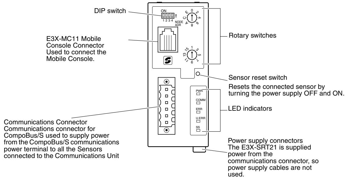
Indicators
The following table shows the meaning of the indicators.
| Indicator | Name | Status | Meaning |
| PWR (green) | Power | ON | The communications power supply is ON. |
| OFF | The communications power supply is OFF. | ||
| COMM (yellow) | Communications | ON | Normal CompoBus/S communications. |
| OFF | A CompoBus/S communications error has occurred or the Unit is in standby status. | ||
| ERR (red) | Communications error | ON | A CompoBus/S communications error has occurred. |
| OFF | Normal CompoBus/S communications or the Unit is in standby status. | ||
| U.WR (red) | Unit error | ON | A Unit error has occurred. |
| OFF | The Unit is communicating normally or is in standby status. | ||
| SS (green) | Sensor communications status | ON | Normal Sensor communications |
| SS (red) | ON | A Sensor communications error has occurred. | |
| SS (---) | OFF | Sensors are in communications wait status or power is turned OFF. |
Switch Settings
Rotary Switches

CompoBus/S node number setting

Number of connected Sensors registered.
Registers the number of connected Sensors. Registering the number of Sensors allows detection of errors in the configuration. Up to 14 Fiber Amplifier Units can be connected, so an error will occur if this switch is set to 15 or 16.
Note Fiber Amplifier Units that use two unit numbers (E3X-DA6TW, E3X-DA8TW) must be counted as two Units when counting the number of Sensors.
DIP Switch
Operating mode setting
Communications mode setting
Reserved for system use
Reserved for system use
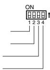
Operating Mode Setting (Pin 1)
This pin sets the operating mode. The maximum number of Fiber Amplifier Units that can be connected and the nodes that each Unit is allocated depends on the operating mode, as follows:
| Pin 1 (MODE) | Maximum number of Fiber Amplifier Units connected | Number of allocated nodes |
| OFF | 6 Units | 1 input node |
| ON | 14 Units | 2 input nodes |
Note Fiber Amplifier Units that use two unit numbers (E3X-DA6TW, E3X-DA8TW) must be counted as two Units when counting the number of Sensors.
Communications Mode Setting (Pin 2)
This pin is used to switch the CompoBus/S communications mode
| Pin 2 (DR) | Communications mode setting |
| OFF | High-speed Communications Mode |
| ON | Long-distance Communications Mode |
Note The Slave communications mode setting must match the communications mode setting of the Master Unit. If the communications modes are different, the Master Unit will not communicate properly. Check the operating status of the Slaves using the indicators.
I/O Allocations
Pin 1 OFF (Up to 6 Sensors)
Up to 6 Sensors can be connected in this mode. The data is 8 bits and is stored in the IN Area, which is set as the node number area
| Bit | Contents |
| 00 | Unit 1 ON/OFF data |
| 01 | Unit 2 ON/OFF data |
| 02 | Unit 3 ON/OFF data |
| 03 | Unit 4 ON/OFF data |
| 04 | Unit 5 ON/OFF data |
| 05 | Unit 6 ON/OFF data |
| 06 | Sensor Communications Error Flag |
| 07 | Sensor Communications Flag |
Sensor Communications Error Flag
Bit 06 turns ON when the registered number of Sensors does not match the number of Sensors that are enabled to communicate, or when a communications error occurs after communications have been established with the Sensors.
Sensor Communications Flag
Bit 07 turns ON when communications are established with the Sensors.
Pin 1 ON (Up to 14 Sensors)
Up to 14 Sensors can be connected in this mode. The data allocated is 16 bits and is stored in the IN Area, as shown in the following table.
| Node number | Node numbers actually used |
| Odd number | Node number setting – 1 to node number setting |
| Even number | Node number setting to node number setting + 1 |
| Odd node number | Even node number | Bit | Contents |
| Node number -1 | Node number | 00 | Unit 1 ON/OFF data |
| 01 | Unit 2 ON/OFF data | ||
| 02 | Unit 3 ON/OFF data | ||
| 03 | Unit 4 ON/OFF data | ||
| 04 | Unit 5 ON/OFF data | ||
| 05 | Unit 6 ON/OFF data | ||
| 06 | Unit 7 ON/OFF data | ||
| 07 | Unit 8 ON/OFF data | ||
| Node number | Node number +1 | 00 | Unit 9 ON/OFF data |
| 01 | Unit 10 ON/OFF data | ||
| 02 | Unit 11 ON/OFF data | ||
| 03 | Unit 12 ON/OFF data | ||
| 04 | Unit 13 ON/OFF data | ||
| 05 | Unit 14 ON/OFF data | ||
| 06 | Sensor Communications Error Flag | ||
| 07 | Sensor Communications Flag |
CompoBus/S Wiring
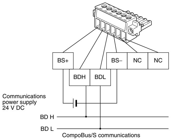
Note
- The power supplied from the CompoBus/S communications power supply is supplied to the Communications Unit and all the Sensors connected to it. Consider the current consumption of the Communications Unit and the Sensors when selecting the power supply. The E3X-SRT21 is a network power supply. Special Flat Cable or 4-conductor VCTF cable can be used to supply power. Check that the allowable current of the communications cable is not exceeded.
- OMRON recommends the following products manufactured by Weidmuller Co., Ltd. for use as crimp terminals.
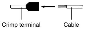
Sleeve (product no.046290)
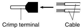
For inserting 2 wires (product no.901851)
Insert cable then crimp
- The following special tool is available:
Crimper PZ1.5 (product no. 900599) manufactured by Weidmuller Co. Ltd.
- The tightening torque for the cable lock screws is 0.2 to 0.4N· m
Dimensions
The following diagram shows the dimensions of the Unit. All dimensions are in mm. The area shown with broken lines indicates the dimensions when the connector is mounted to the Unit.
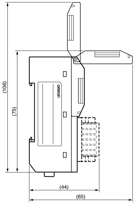
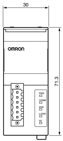
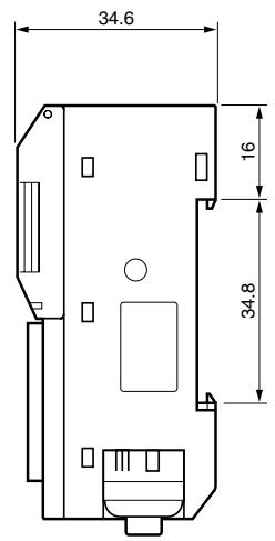
5-7 Analog Input Terminals
5-7-1 SRT2-AD04 Analog Input Terminal
Note Do not connect the Analog Input Terminal to any of the following incompatible Master Units or incorrect data may be transmitted.
| PLC | Incompatible Master Units | Compatible Master Units |
| CS-series, C200HX/ C200HG/ C200HE-(Z)E, and C200HS | C200HW-SRM21 | C200HW-SRM21-V1 |
| CS-series | --- | CS1W-SRM21 |
| CJ-series | --- | CJ1W-SRM21 |
| CQM1 | CQM1-SRM21 | CQM1-SRM21-V1 |
| SRM1 (Integrated with CPU Unit) | SRM1-C0□SRM1-C0□-V1 | SRM1-C0□-V2 |
| CPM2C-S (Integrated with CPU Unit) | --- | All Units |
The Analog Input Terminal is also incompatible with the following Master Units:
3G8B3-SRM0□ CompoBus/S VME Board
C200PC-ISA□2-SRM SYSMAC Board
Specifications
The following tables show the ratings and input specifications for the SRT2-AD04.
General Specifications
| Item | Specification |
| Model | SRT2-AD04 |
| Input points | 4, 3, 2, or 1 points (switchable using DIP switch) (4, 3, 2, or 1 words are allocated to the Master.) |
| Power supply type | Network power supply |
| Communications power supply voltage | 14 to 26.4 V DC (Power can be supplied from the communications cable.) |
| Current consumption | Communications power: 100 mA max. |
| Noise immunity | ±1.5 kVp-p with a pulse width of 0.1 to 1 μs and a rise time of 1 ns (via impulse noise simulator) |
| Vibration resistance | 10 to 55 Hz, 1.0-mm double amplitude |
| Shock resistance | 200 m/s² |
| Dielectric strength | 500 V AC for 1 minute (between insulated circuits) |
| Insulation resistance | 20 MΩ min. at 250 V DC (between insulated circuits) |
| Ambient temperature | Operating: -10 to 55°C Storage: -25 to 65°C |
| Ambient humidity | Operating: 25% to 85% (with no condensation) Storage: 25% to 85% (with no condensation) |
| Operating environment | No corrosive gases |
| Mounting method | M4 screws or 35-mm DIN track mounting |
| Mounting strength | 50 N Track direction: 10 N |
| Terminal strength | Pulling: 50 N |
| Weight | Approx. 120 g |
Input Specifications
| Item | Specification | ||
| Voltage input | Current input | ||
| Input signal range | 0 to 5 V1 to 5 V0 to 10 V-10 to 10 V | 0 to 20 mA4 to 20 mA | |
| Input signal range settings for Input 0 and Input 1 are shared.Input signal range settings for Input 2 and Input 3 are shared. | |||
| Max. signal input | ±15 V | ±30 mA | |
| Input impedance | 1 MΩ min. | Approx. 250 Ω | |
| Resolution | 1/6000 (Full scale) | ||
| General precision | 25°C | ±0.3%FS | ±0.4%FS |
| 0 to 55°C | ±0.6%FS | ±0.8%FS | |
| Conversion time | 1 ms/point (4 ms/4 points, 3 ms/3 points, 2 ms/2 points, or 1 ms/1 point) | ||
| AD conversion output data | Binary data-10 to 10 V: Full scale F448 to 0 to 0BB8 HexOther: Full scale 0000 to 1770 Hex | ||
| Averaging Function | Can be set (with DIP switch) | ||
| Burnout detection function | Available | ||
| Insulation method | Between analog input and communications line: Photo-couplerBetween each analog input signal: Non-insulated | ||
Slave Components
The following diagram shows the main components of the SRT2-AD04 Analog Input Terminal. The functions of these components are described below.
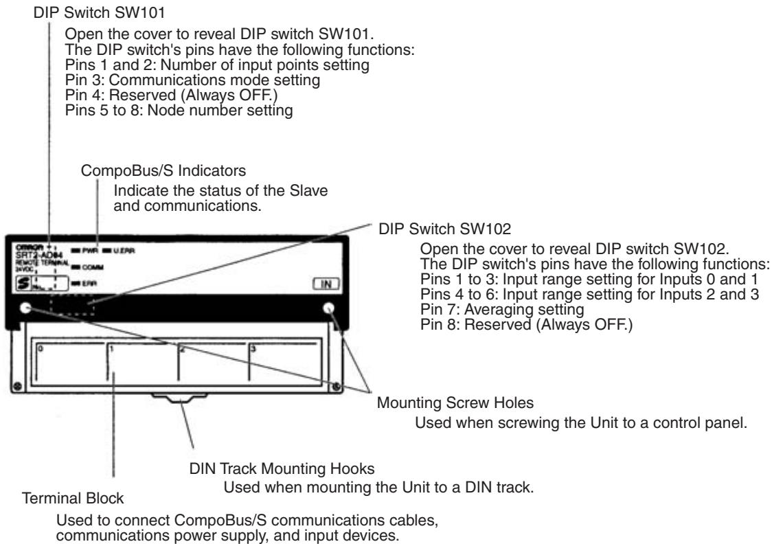
Indicators
The following table shows the meaning of the indicators.
| Indicator | Status | Meaning |
| PWR (green) | ON | The communications power supply is ON. |
| OFF | The communications power supply is OFF. | |
| COMM (yellow) | ON | Normal communications |
| OFF | A communications error has occurred or the Unit is in standby status. | |
| ERR (red) | ON | A communications error has occurred. |
| OFF | Normal communications or the Unit is in standby status. | |
| U.JRR (red) | ON | An error has occurred in the Unit. |
| OFF | Normal communications or the Unit is in standby status. |
DIP Switches
Always turn OFF the Slave before changing DIP switch settings.
SW101
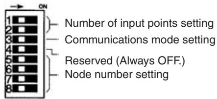
| Pin 1 | Pin 2 | Number of input points setting |
| OFF | OFF | 4 points (Factory setting) |
| OFF | ON | 3 points (Inputs 0 to 2 valid) |
| ON | OFF | 2 points (Inputs 0 and 2 valid) |
| ON | ON | 1 point (Input 0 valid) |
| Pin 3 | Communications mode setting |
| OFF | High-speed Communications Mode (Factory setting) |
| ON | Long-distance Communications Mode |
| Pin 4 | Always set to OFF. |
Note Make sure that the communications mode of the Slave is the same as that of the Master Unit. If the communications modes are not the same, normal communications with the Master Unit will not be possible. The operating status of the Slave can be verified with LED indicators. Refer to 6-5-1 Indicators for details.
Node Number Setting
Set the node number with pins 5 through 8, as shown in the following table.
| Node number | Pin 5 (8) | Pin 6 (4) | Pin 7 (2) | Pin 8 (1) |
| 0 | OFF | OFF | OFF | OFF |
| 1 | OFF | OFF | OFF | ON |
| 2 | OFF | OFF | ON | OFF |
| 3 | OFF | OFF | ON | ON |
| 4 | OFF | ON | OFF | OFF |
| 5 | OFF | ON | OFF | ON |
| 6 | OFF | ON | ON | OFF |
| 7 | OFF | ON | ON | ON |
| 8 | ON | OFF | OFF | OFF |
| 9 | ON | OFF | OFF | ON |
| 10 | ON | OFF | ON | OFF |
| 11 | ON | OFF | ON | ON |
| 12 | ON | ON | OFF | OFF |
| 13 | ON | ON | OFF | ON |
| 14 | ON | ON | ON | OFF |
| 15 | ON | ON | ON | ON |
A single Analog Input Terminal is allocated 64 points, 48 points, 32 points, or 16 points. Points are assigned as shown in the following table. Note that when a CQM1 Master Unit is used in 4-point mode, the Analog Input Terminal cannot be connected.
| Allocated points | Node number setting | Node number actually used |
| 64 points (4 inputs) | Odd | Node number setting - 1 to node num- ber setting + 6 |
| Even | Node number setting to node number setting + 7 | |
| 48 points (3 inputs) | Odd | Node number setting - 1 to node num- ber setting + 4 |
| Even | Node number setting to node number setting + 5 | |
| 32 points (2 inputs) | Odd | Node number setting - 1 to node num- ber setting + 2 |
| Even | Node number setting to node number setting + 3 | |
| 16 points (1 input) | Odd | Node number setting - 1 to node num- ber setting |
| Even | Node number setting to node number setting + 1 |
SW102
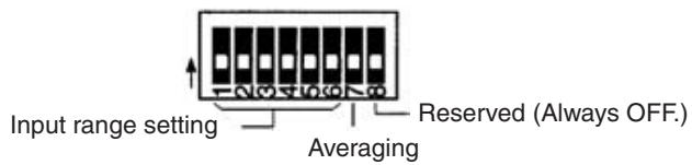
| Pin 1 | Pin 2 | Pin 3 | Range setting for Inputs 0 and 1 |
| Pin 4 | Pin 5 | Pin 6 | Range setting for Inputs 2 and 3 |
| OFF | OFF | OFF | 0 to 5 V (Factory setting) |
| ON | OFF | OFF | 1 to 5 V |
| OFF | ON | OFF | 0 to 10 V |
| ON | ON | OFF | -10 to 10 V |
| OFF | OFF | ON | 4 to 20 mA |
| ON | OFF | ON | 0 to 20 mA |
| Do not set to any values but those given above. | |||
| Pin 7 | Averaging |
| OFF | No averaging (Factory setting) |
| ON | With averaging (8-time moving average) |
| Pin 8 | Always set to OFF. |
Note Input range settings for Input 0 and Input 1 are shared, and those for Input 2 and Input 3 are shared. An example is shown below.
Input 0 and Input 1: 4 to 20mA (Pins 1, 2, 3 = OFF, OFF, ON)
Input 2 and Input 3: 1 to 5V (Pins 4, 5, 6 = ON, OFF, OFF)
Internal Circuits
The following diagram shows the internal circuits for the SRT2-AD04.
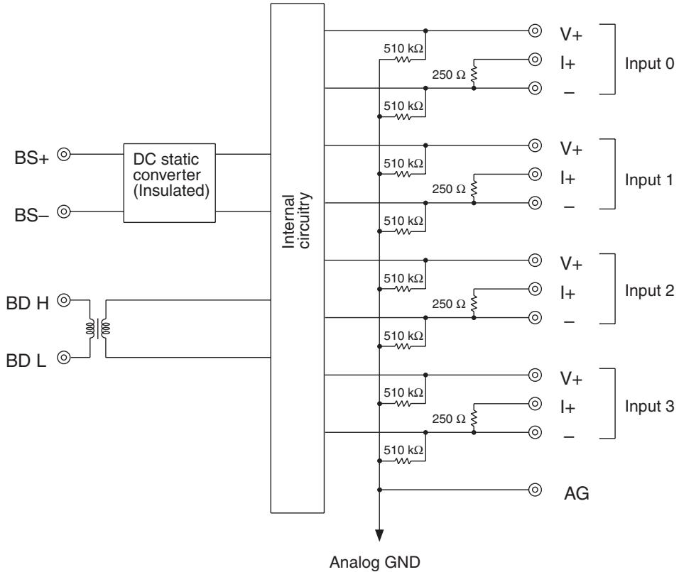
Terminal Block
Install the following M3 crimp terminals on the signal wires and connect them to the terminal block.
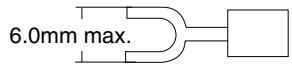
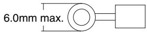
Note Tighten the terminal block screws to the specified tightening torque of 0.5 N·m.
The following diagram shows the terminal block for the SRT2-AD04.
| BDH | BS+ | AG | V0+ | I0+ | V1+ | I1+ | V2+ | I2+ | V3+ | I3+ | ||||||||||
| BDL | BS- | NC | AG | 0- | NC | 1- | NC | 2- | NC | 3- | ||||||||||
Note For current input, short terminals V + and I + .
Wiring
Wire the connector terminals of the Analog Input Terminal as shown below according to voltage input or current input.
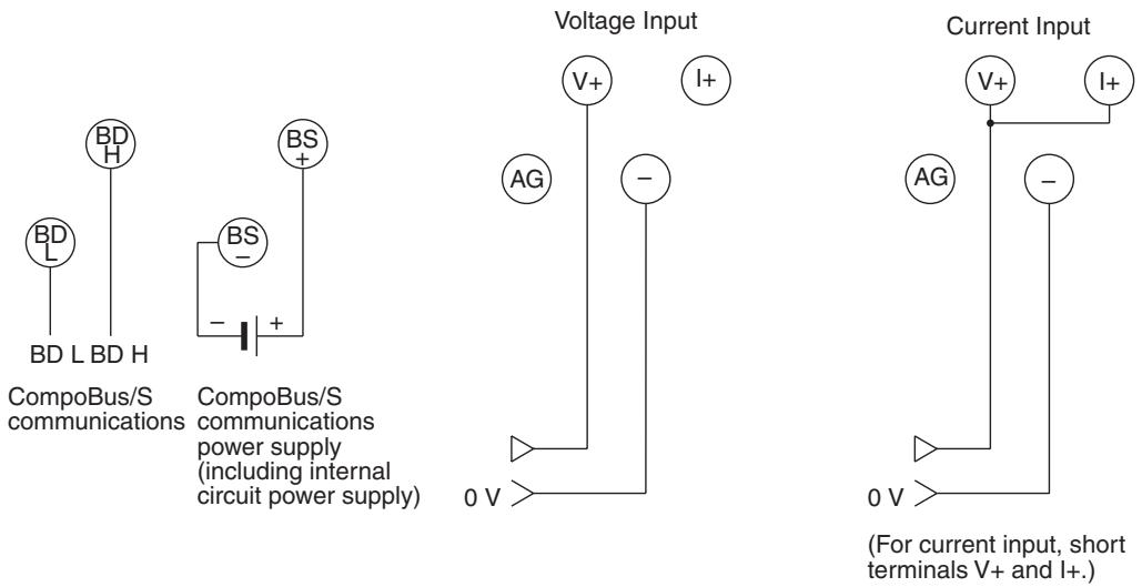
For current input, short terminals V+ and I+ . Use the short circuiting fitting provided to accomplish this.
Input Range and Conversion Data
The analog data that is input will be converted to digital values according to the input range.
Note If the input range is surpassed, the AD conversion data will be fixed at the upper or lower limit.
-10 to 10 V
Voltages between -10V and 10V correspond to F448 to 0BB8 Hex (-3000 to 3000). The range of data that can be converted is F31C to 0CE4 Hex (-3300 to 3300). When voltage is negative, it is expressed as 2's complement (16
bits). In the event of disconnection, the data becomes the same value as in the case of 0V input (0000 Hex).
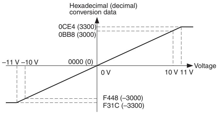
0 to 10 V
Voltages between 0 V and 10 V correspond to 0000 to 1770 Hex (0 to 6000). The range of data that can be converted is FED4 to 189C Hex (-300 to 6300). When voltage is negative, it is expressed by 2's complement (16 bits). In the event of disconnection, the data becomes the same value as in the case of 0 V input (0000 Hex).
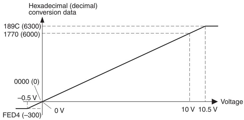
0 to 5 V
Voltages between 0 V and 5 V correspond to 0000 to 1770 Hex (0 to 6000). The range of data that can be converted is FED4 to 189C Hex (-300 to 6300). When voltage is negative, it is expressed by 2's complement (16 bits). In the event of disconnection, the data becomes the same value as in the case of 0 V input (0000 Hex).
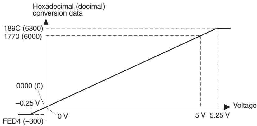
1 to 5 V
Voltages between 1 V and 5 V correspond to 0000 to 1770 Hex (0 to 6000). The range of data that can be converted is FED4 to 189C Hex (-300 to 6300).
When voltage is less than the input range (i.e., input voltage is less than 0.8V ), the burnout detection function is activated, and data becomes 7FFF.

0 to 20 mA
Currents between 0 mA and 20 mA correspond to 0000 to 1770 Hex (0 to 6000). The range of data that can be converted is FED4 to 189C Hex (-300 to 6300). When current is negative, it is expressed by 2's complement (16 bits). In the event of disconnection, the data becomes the same value as in the case of 0 mA input (0000 Hex).
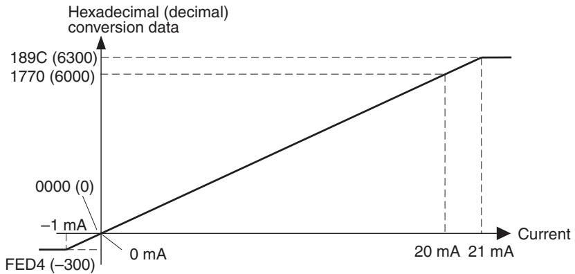
4 to 20 mA
Currents between 4 mA and 20 mA correspond to 0000 to 1770 Hex (0 to 6000). The range of data that can be converted is FED4 to 189C Hex (-300 to 6300). When current is less than the input range (i.e., input current is less than 3.2mA ) the burnout detection function is activated, and data becomes 7FFF.
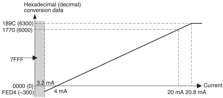
Switching between 4, 3, 2, and 1 Inputs
It is possible to restrict the number of inputs with pins 1 and 2 of DIP switch SW101. In this way, the sampling cycle can be set to 4 ms/4 points, 3 ms/3
Averaging Function (8-time Moving Average)
points, 2 ms/2 points, or 1 ms/1 point, making conversions faster. In accordance with the number of inputs, the number of words allocated to the Analog Input Terminal in the PLC for the Master Unit will also be set to 4 words/4 points, 3 words/3 points, 2 words/2 points, or 1 word/1 point. When the number of inputs is 3, Inputs 0, 1, and 2 will be used; when the number of inputs is 2, Inputs 0 and 2 will be used; and when the number of inputs is 1, Input 0 will be used.
When pin 7 of DIP switch SW102 is ON, the averaging function (8-time moving average) will be activated for all Inputs 0 to 3.
The averaging function outputs the average of the previous 8 inputs (moving average) as conversion data.
Turn ON this pin when the inputs fluctuate slightly but frequently as shown in the following figure. The averaging function will make the actual inputs smoother.
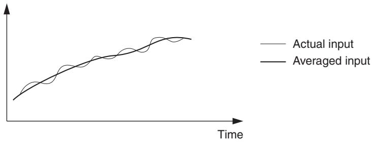
Note Even in this case, conversion data will be updated at the normal rate of 1 ms/ point. After power is turned ON, the data transmitted first are sampled 8 times, averaged, and then output.
Burnout Detection Function
When the input range is 1 to 5V or 4 to 20mA , and the input signal is less than 0.8V or less than 3.2mA , the input line is deemed to be disconnected, and the burnout detection function is activated. Once the burnout detection function is activated, the conversion data is set to 7FFF Hex.
The time required to activate or cancel the burnout detection function is the same as the time required for conversion.
If input returns to the convertible range, the burnout detection function will be cancelled automatically, and normal data conversion will be resumed.
Precautions on Using Shared Power Supply for Input Devices
If the power supply is shared by input devices, and a disconnection occurs during voltage input, the status of the circuit becomes as shown in the follow-
ing figure. (There is no effect during current input, even if the power supply is shared.)
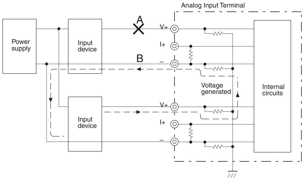
When portion A in the above diagram is disconnected, the sneak circuit indicated by will be formed. As a result, despite the disconnection, a voltage equivalent to 1/2 to 1/3 of the output of the connected input device is generated at the disconnected input device. (The same is true if portion B is disconnected.) When this kind of voltage is generated, the burnout detection function may fail to activate.
For voltage input, either do not have the power supply shared by the input devices, or use an isolator for each input.
AD Conversion Data
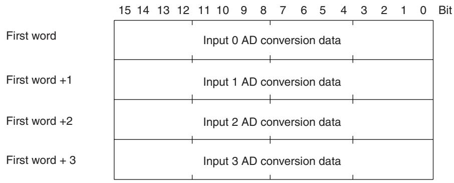
When the AD conversion data becomes negative, it is expressed as 2's complement. The NEG instruction can be used to obtain the absolute value from this 2's complement.
Conversion Time
AD conversion data is updated every 1 ms for each point.
SRT2-AD04 Dimensions
The following diagram shows the dimensions for the SRT2-AD04. All dimensions are in mm.
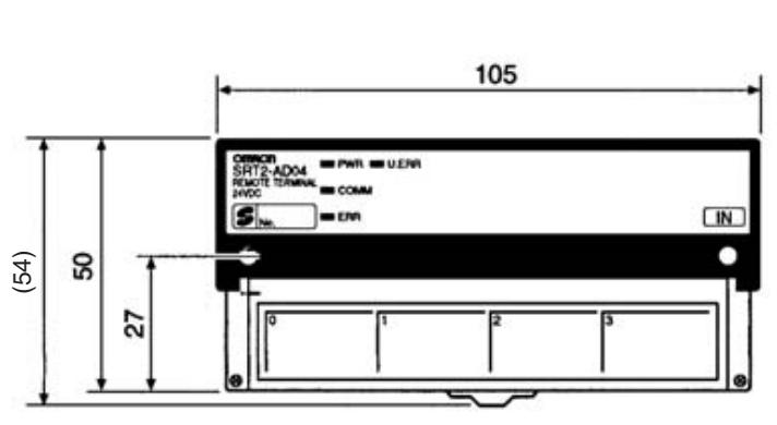
Mounting Holes
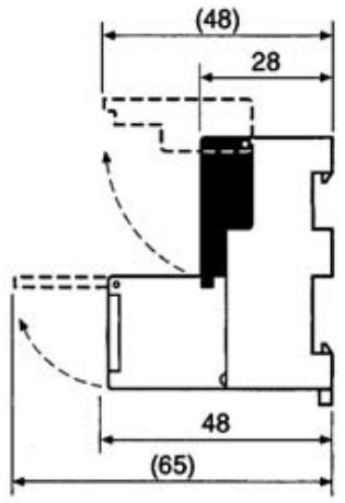
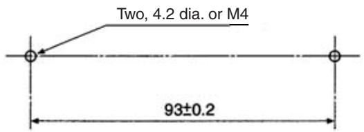
Note To prevent damage from static electricity, mount the Unit where it cannot be touched accidentally.
5-8 Analog Output Terminals
5-8-1 SRT2-DA02 Analog Output Terminal
Note Do not connect the Analog Output Terminal to any of the following incompatible Master Units or incorrect data may be transmitted.
| PLC | Incompatible Master Units | Compatible Master Units |
| CS-series, C200HX/ C200HG/ C200HE-(Z)E, and C200HS | C200HW-SRM21 | C200HW-SRM21-V1 |
| CS-series | --- | CS1W-SRM21 |
| CJ-series | --- | CJ1W-SRM21 |
| CQM1 | CQM1-SRM21 | CQM1-SRM21-V1 |
| SRM1 (Integrated with CPU Unit) | SRM1-C0□SRM1-C0□-V1 | SRM1-C0□-V2 |
| CPM2C-S (Integrated with CPU Unit) | --- | All Units |
The Analog Output Unit is also incompatible with the following Master Units:
3G8B3-SRM0□ CompoBus/S VME Board
C200PC-ISA□2-SRM SYSMAC Board
SDD-CS1 NKE Corporation UNI-WIRE Send Unit
Specifications
The following tables show the ratings and output specifications for the SRT2-DA02.
General Specifications
| Item | Specification |
| Model | SRT2-DA02 |
| Output points | 2 or 1 points (switchable using DIP switch) (2 or 1 words are allocated to the Master.) |
| Power supply type | Network power supply |
| Communications power supply voltage | 14 to 26.4 V DC (Power cannot be supplied from the communications cable) |
| Current consumption | Communications power: 170 mA max. |
| Noise immunity | ±1.5 kVp-p with a pulse width of 0.1 to 1 μs and a rise time of 1 ns (via impulse noise simulator) |
| Vibration resistance | 10 to 55 Hz, 1.0-mm double amplitude |
| Shock resistance | 200 m/s² |
| Dielectric strength | 500 V AC (between insulated circuits) |
| Insulation resistance | 20 MΩ min. at 250 V DC (between insulated circuits) |
| Ambient temperature | Operating: -10 to 55°C Storage: -25 to 65°C |
| Ambient humidity | Operating: 25% to 85% (with no condensation) Storage: 25% to 85% (with no condensation) |
| Operating environment | No corrosive gases |
| Mounting method | M4 screws or 35-mm DIN track mounting |
| Mounting strength | 50 N Track direction: 10 N |
| Terminal strength | Pulling: 50 N |
| Weight | Approx. 100 g |
Output Specifications
| Item | Specification | ||
| Voltage output | Current output | ||
| Output signal range | 0 to 5 V1 to 5 V0 to 10 V-10 to 10 V | 4 to 20 mA | |
| Output signal range is set separately for Output 0 and Output 1. | |||
| Allowable load resis-tance of external output | 5 k Ω min. | 600 Ω max. | |
| External output impedance | 0.5 Ω max. | --- | |
| Resolution | 1/6,000 (Full scale) | ||
| General precision | 25°C | ±0.4%FS | |
| 0 to 55°C | ±0.8%FS | ||
| Conversion time | 2 ms/2 points (2 outputs) or 2 ms/1 point (1 output) | ||
| DA conversion input data | Binary data-10 to 10 V: Full scale F448 to 0 to 0BB8 HexOther: Full scale 0000 to 1770 Hex | ||
| Insulation method | Between analog output and communications line: Photo-couplerBetween each analog output signal: Non-insulated | ||
Slave Components
The following diagram shows the main components of the SRT2-DA02 Analog Output Terminal. The functions of these components are described below.

Indicators
The following table shows the meaning of the indicators.
| Indicator | Status | Meaning |
| PWR (green) | ON | The communications power supply is ON. |
| OFF | The communications power supply is OFF. | |
| COMM (yellow) | ON | Normal communications |
| OFF | A communications error has occurred or the Unit is in standby status. | |
| ERR (red) | ON | A communications error has occurred. |
| OFF | Normal communications or the Unit is in standby status. | |
| U.JRR (red) | ON | An error has occurred in the Unit. |
| OFF | Normal communications or the Unit is in standby status. |
DIP Switches
Always turn OFF the Slave before changing DIP switch settings.
SW101
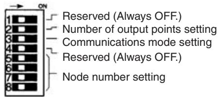
| Pin 1 | Always set to OFF. |
| Pin 2 | Number of output points setting |
| OFF | 2 points (Factory setting) |
| ON | 1 point (Output 0 valid) |
| Pin 3 | Communications mode setting |
| OFF | High-speed Communications Mode (Factory setting) |
| ON | Long-distance Communications Mode |
| Pin 4 | Always set to OFF. |
Note Make sure that the communications mode of the Slave is the same as that of the Master Unit. If the communications modes are not the same, normal communications with the Master Unit will not be possible. The operating status of the Slave can be verified with LED indicators. Refer to 6-5-1 Indicators for details.
Node Number Setting
Set the node number with pins 5 through 8, as shown in the following table.
| Node number | Pin 5 (8) | Pin 6 (4) | Pin 7 (2) | Pin 8 (1) |
| 0 | OFF | OFF | OFF | OFF |
| 1 | OFF | OFF | OFF | ON |
| 2 | OFF | OFF | ON | OFF |
| 3 | OFF | OFF | ON | ON |
| 4 | OFF | ON | OFF | OFF |
| 5 | OFF | ON | OFF | ON |
| 6 | OFF | ON | ON | OFF |
| 7 | OFF | ON | ON | ON |
| 8 | ON | OFF | OFF | OFF |
| 9 | ON | OFF | OFF | ON |
| 10 | ON | OFF | ON | OFF |
| 11 | ON | OFF | ON | ON |
| 12 | ON | ON | OFF | OFF |
| 13 | ON | ON | OFF | ON |
| 14 | ON | ON | ON | OFF |
| 15 | ON | ON | ON | ON |
A single Analog Output Terminal is allocated either 32 points or 16 points. Points are assigned as shown in the following table. Note that when CQM1 Master Unit is used in 4-point mode, an Analog Output Terminal cannot be connected.
| Allocated points | Node number setting | Node number actually used |
| 32 points (2 outputs) | Odd | Node number setting – 1 to node num- ber setting + 2 |
| Even | Node number setting to node number setting + 3 | |
| 16 points (1 output) | Odd | Node number setting – 1 to node num- ber setting |
| Even | Node number setting to node number setting + 1 |
SW102
Output range setting Output setting for communications error
| Pin 1 | Pin 2 | Pin 3 | Range setting for Output 0 |
| Pin 4 | Pin 5 | Pin 6 | Range setting for Output 1 |
| OFF | OFF | OFF | 0 to 5 V (Factory setting) |
| ON | OFF | OFF | 1 to 5 V |
| OFF | ON | OFF | 0 to 10 V |
| ON | ON | OFF | -10 to 10 V |
| OFF | OFF | ON | 4 to 20 mA |
| Do not set to any values but those given above. | |||
| Pin 7 | Pin 8 | Output setting for communications error |
| OFF | OFF | Clear to lower output limit (Factory setting) |
| OFF | ON | Clear to upper output limit |
| ON | OFF | 0 V output (When output range is -10 to 10 V.) Clear to lower output limit (Any other time.) |
| ON | ON | Hold output |
Note Output range is set separately for Output 0 and Output 1. An example is shown below.
Output 0: 4 to 20mA (Pins 1, 2, 3 = OFF, OFF, ON)
Output 1: 1 to 5 V (Pins 4, 5, 6 = ON, OFF, OFF)
Internal Circuits
The following diagram shows the internal circuits for the SRT2-DA02.
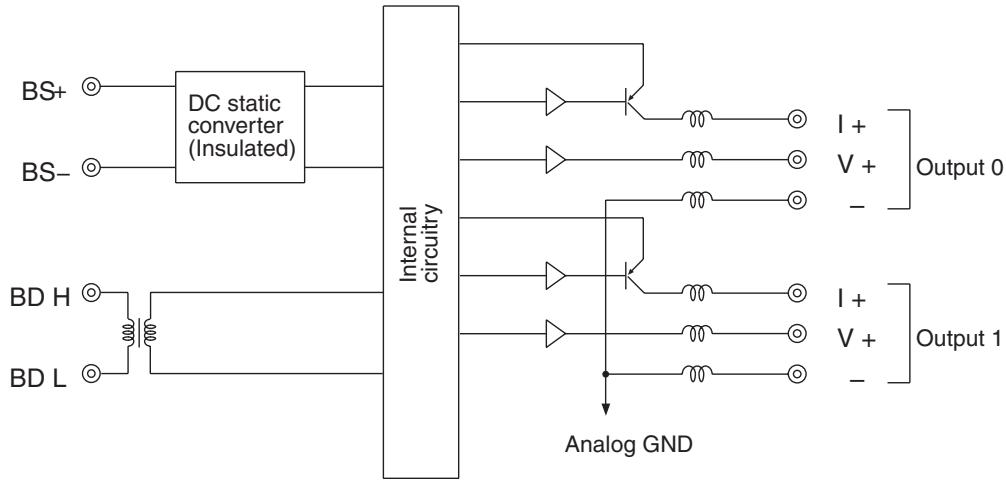
Terminal Block
Install the following M3 crimp terminals on the signal wires and connect them to the terminal block.

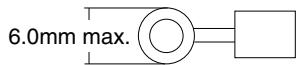
Note Tighten the terminal block screws to the specified tightening torque of 0.5 N·m.
The following diagram shows the terminal block for the SRT2-DA02.
| BDH | BS+ | NC | NC | V0+ | I0+ | V1+ | I1+ | ||||||
| BDL | BS- | NC | NC | NC | 0- | NC | 1- | ||||||
Wiring
Wire the connector terminals of the Analog Output Terminal as shown below according to voltage output or current output.
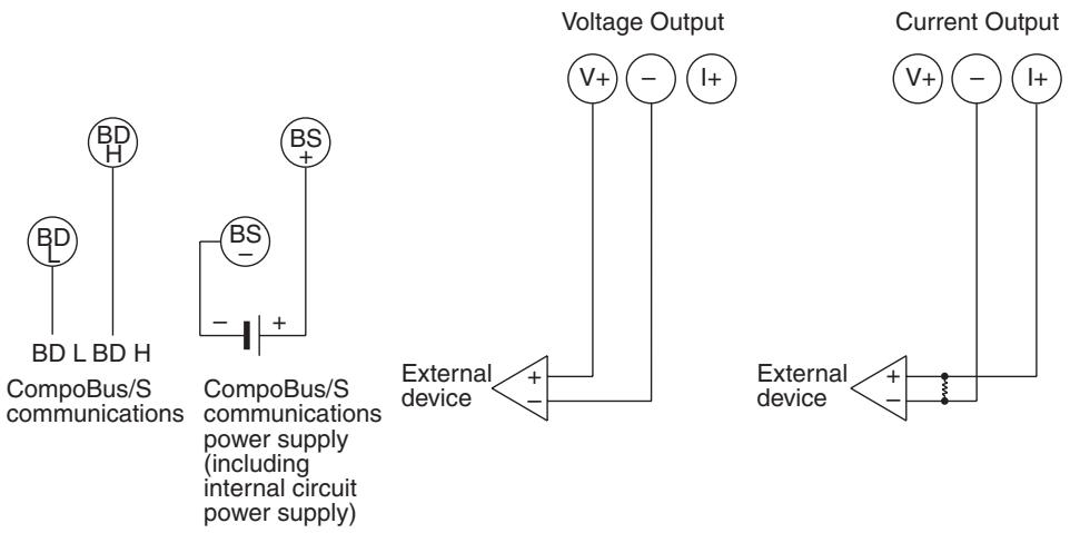
Output Range and Conversion Data
The digital values that are input are converted to analog data according to the output range.
1 to 5 V
Values 0000 to 1770 Hex (0 to 6000) correspond to voltages between 1 and 5 V. The output range is 0.8 to 5.2 V.
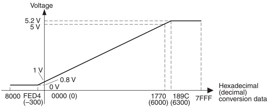
0 to 5 V
Values 0000 to 1770 Hex (0 to 6000) correspond to voltages between 0 and 5 V. The output range is -0.25 to 5.25V .
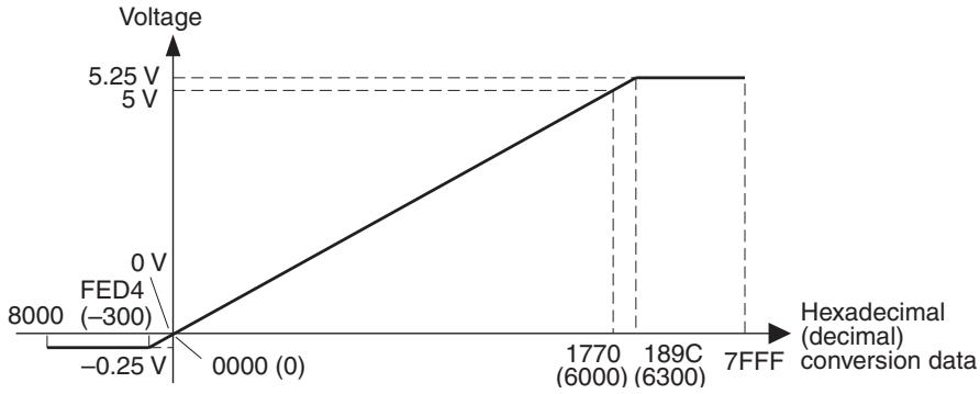
0 to 10 V
Values 0000 to 1770 Hex (0 to 6000) correspond to voltages between 0 and 10 V. The output range is -0.5 to 10.5 V.
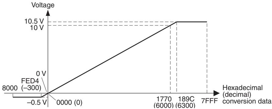
-10 to 10 V
Values F448 to 0BB8 Hex (-3000 to 3000) correspond to voltages between -10 and 10V . The output range is -11 to 11V .
Negative voltages are specified as 2's complement (16 bits).
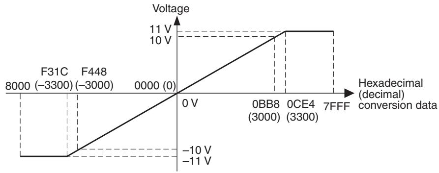
4 to 20 mA
Values 0000 to 1770 Hex (0 to 6000) correspond to currents between 4 and 20mA . The output range is 3.2 to 20.8mA .
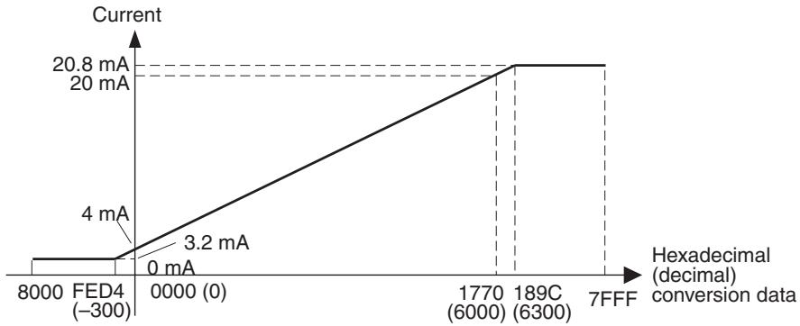
Switching between 2 and 1 Outputs
It is possible to restrict the number of outputs with pin 2 of DIP switch SW101. In accordance with the number of outputs, the number of words allocated to the Analog Output Terminal in the PLC for the Master Unit will also be set to 2 words/2 points or 1 word/1 point. When the number of outputs is 2, Outputs 0 and 1 will be used; and when the number of outputs is 1, Output 0 will be used.
Output Data During Communications Error
Pins 7 and 8 of DIP switch SW102 are used to select one of the following methods for processing output data when a communications error occurs in the CompoBus/S System.
Pin 7 OFF, Pin 8 OFF: Clear to lower limit value
Pin 7 OFF, Pin 8 ON: Clear to upper limit value
Pin 7 ON, Pin 8 OFF: Clear to 0V (when voltage range is -10 to 10V .) Clear to lower limit value (All other times.)
Pin 7 ON, Pin 8 ON: Hold the value immediately preceding error
When the pins are set at Low Clear, High Clear, or 0V , output data will become as shown in the following table.
| Output range | Pin 7 OFF, Pin 8 OFF | Pin 7 OFF, Pin 8 ON | Pin 7 ON, Pin 8 OFF |
| 0 to 5 V | -0.25 V | 5.25 V | -0.25 V |
| 1 to 5 V | 0.8 V | 5.2 V | 0.8 V |
| 0 to 10 V | -0.5 V | 10.5 V | -0.5 V |
| -10 to 10 V | -11 V | 11 V | 0 V |
| 4 to 20 mA | 3.2 mA | 20.8 mA | 3.2 mA |
DA Conversion Data
In the Master Unit, DA conversion data should be output as shown in the following diagram.
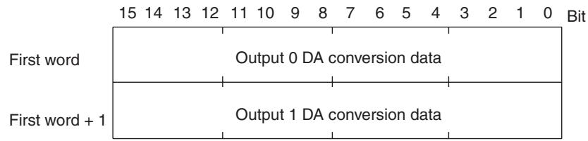
To output a negative voltage is output, specify DA conversion data as 2's complement. The NEG instruction can be used to obtain the 2's complement from the absolute value.
Conversion Time
DA conversion data is updated every 2 ms irrespective of the number of output points.
SRT2-DA02 Dimensions
The following diagram shows the dimensions for the SRT2-DA02. All dimensions are in mm.
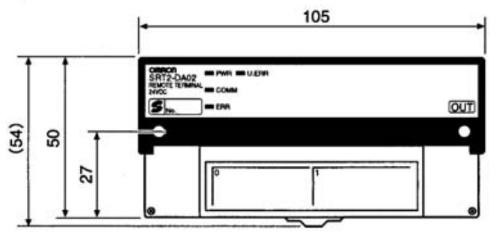
Mounting Holes

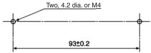
Note To prevent damage from static electricity, mount the Unit where it cannot be touched accidentally.
5-9 I/O Link Units for CPM1A and CPM2A
5-9-1 CPM1A-SRT21 I/O Link Unit for CPM1A and CPM2A
Specifications
The following table shows the ratings and I/O specifications for the CPM1A-SRT21.
Ratings
| Item | Specification |
| Model | CPM1A-SRT21 |
| I/O points | 8 input points, 8 output points (All the I/O points use the same node number. I/O is per-formed only with I/O memory of CPM1A/CPM2A, not with external devices.) |
| Connection to CPM1A/ CPM2A | Connect expansion I/O connecting cable to the expansion connector of the CPU Unit or the Expansion Unit. |
| Power supply type | --- |
| Communications power supply and internal circuits power supply | Supplied from CPM1A or CPM2A CPU Unit. (See note.) |
| Vibration resistance | Conforming to JIS C0911 10 to 57 Hz with single-amplitude of 0.075 mm 57 to 150 Hz with fixed acceleration of 9.8 m/s² 80 minutes each in X, Y, and Z directions (8 minutes per sweep × 10 sweeps = 80 minutes) |
| Shock resistance | Conforming to JIS C0912 Peak acceleration of 147 m/s² 3 times each in X, Y, and Z directions |
| Ambient temperature | Operating: 0 to 55°C (with no icing or condensation) Storage: -20 to 75°C (with no icing or condensation) |
| Ambient humidity | Operating: 10% to 90% (with no condensation) Storage: 10% to 90% (with no condensation) |
| Operating environment | No corrosive gases |
| Node number settings | The node number is set on a DIP switch. (Set the node number before turning ON the CPM1A or CPM2A CPU Unit.) |
| Weight | Approx. 200 g |
Note CompoBus/S communications and common I/O terminals are not used.
Slave Components
The following diagram shows the main components of the CPM1A-SRT21 I/O Link Unit for CPM1A/CPM2A. The functions of these components are described below.

Mounting Screw Holes
Used when screwing the Unit to a control panel.
Indicators
The following table shows the meaning of the indicators.
| Indicator | Name | Status | Meaning |
| COMM (yellow) | Communications | ON | Normal communications. |
| OFF | A communications error has occurred or the Unit is in standby status. | ||
| ERR (red) | Communications error | ON | A communications error has occurred. |
| OFF | Normal communications or the Unit is in standby status. |
DIP Switch
Always turn OFF the CPM1A or CPM2A CPU Unit before changing DIP switch settings.
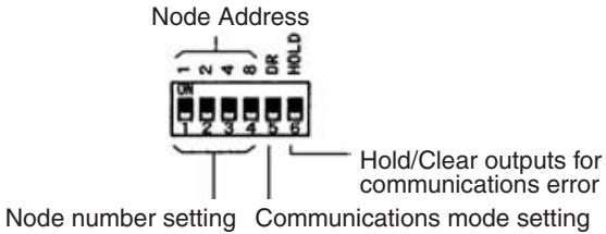
Node Number Setting
Set the node number with pins 1 through 4, as shown in the following table.
| Node number | Pin 4 (8) | Pin 3 (4) | Pin 2 (2) | Pin 1 (1) |
| 0 | OFF | OFF | OFF | OFF |
| 1 | OFF | OFF | OFF | ON |
| 2 | OFF | OFF | ON | OFF |
| 3 | OFF | OFF | ON | ON |
| 4 | OFF | ON | OFF | OFF |
| 5 | OFF | ON | OFF | ON |
| 6 | OFF | ON | ON | OFF |
| 7 | OFF | ON | ON | ON |
| 8 | ON | OFF | OFF | OFF |
| 9 | ON | OFF | OFF | ON |
| 10 | ON | OFF | ON | OFF |
| 11 | ON | OFF | ON | ON |
| 12 | ON | ON | OFF | OFF |
| 13 | ON | ON | OFF | ON |
| 14 | ON | ON | ON | OFF |
| 15 | ON | ON | ON | ON |
Note 1. All the 8 input and 8 output points use the same node number.
2. The actual node number setting range depends on the type of PLC in which the Master is mounted as well as the Master's settings. Refer to 2-1 Communications Specifications for details.
Communications Mode Settings
The following communications modes are set with pin 5.
| Pin 5 (DR) | Communications mode | Communications distance | Communications baud rate | Communications cycle time |
| OFF | High-speed Communications Mode | 100 m max. | 750 kbps | 0.5 or 0.8 ms |
| ON | Long-distance Communications Mode (see note 1) | 500 m max. | 93.75 kbps | 4.0 or 6.0 ms |
Note
- Only the C200HW-SRM21-V1, CQM1-SRM21-V1, CPM2C-S, and SRM1-C0□-V2 Master Units can use Long-distance Communications Mode.
- Make sure that the communications mode of the Slave is the same as that of the Master Unit. If the communications modes are not the same, normal communications with the Master Unit will not be possible. The operating status of the Slave can be verified with LED indicators. Refer to 6-5-1 Indicators for details.
Hold/Clear Outputs for Communications Error
Pin 6 is used to set the output data status when a communications error occurs, as shown in the following table.
| Pin 6 (HOLD) | Setting |
| OFF | Clear output status. |
| ON | Maintain output status. |
Terminal Arrangement and Wiring
The following diagram shows the terminal arrangement and wiring for the CPM1A-SRT21.
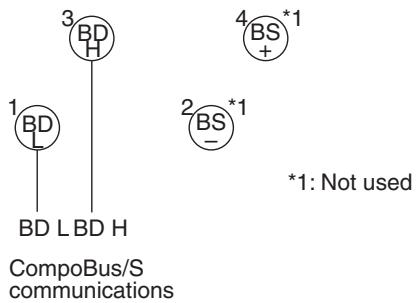
When viewed from the CPM1A or CPM2A CPU Unit, the 8 input and 8 output points under the CompoBus/S I/O Link Unit are allocated to the I/O memory (input and output bits) of the CPU Unit, as is the case with Expansion I/O Units. However, actual I/O operation is not performed for the I/O memory of the CPM1A or CPM2A CPU Unit, but it is performed for the I/O memory of the CPU Unit in which the CompoBus/S Master Unit is mounted.
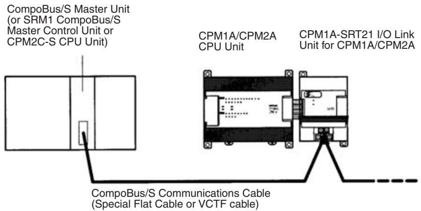
Allocation to CPM1A/ CPM2A I/O Bits
As with other Expansion I/O Units for the CPM1A and CPM2A, both input and output bits for the I/O Link Unit start with the word following the last word allocated to the CPM1A or CPM2A CPU Unit or the previous Expansion I/O Unit to which it is connected. If the last input word allocated to the CPM1A/CPM2A CPU Unit or the previous Expansion Unit is word m, and the last output word allocated to that Unit is word n, word allocations are as shown in the following figure.
I/O Link Unit for CPM1A/CPM2A
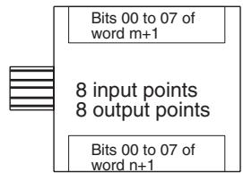
For example, an I/O Link Unit for CPM1A/CPM2A can be connected to the first 30-point I/O CPM2A CPU Unit as shown in the following figure.
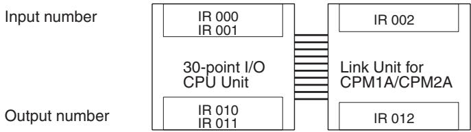
Allocation to Master CPU Unit
The 8 input and 8 output points allocated to the I/O memory of the CPM1A or CPM2A CPU Unit are allocated to the Special I/O Unit data area of the Master CPU Unit according to the node number.
Both 8 input and 8 output points use the same node number.
For example, if the range of node numbers IN0 to IN7 and OUT0 to OUT7 is set, and node number 0 is used, data will be input from bits 00 to 07 of word n (Output Slave 0) and data will be output to bits 00 to 07 of word n + 4 (Input Slave 0).
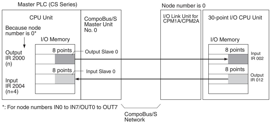
5-10 I/O Link Units for CPM2C
5-10-1 CPM2C-SRT21 I/O Link Unit for CPM2C
Specifications
The following table shows the ratings and I/O specifications for the CPM2C-SRT21.
Ratings
| Item | Specification |
| Model | CPM2C-SRT21 |
| I/O points | 8 input points, 8 output points (All the I/O points use the same node number. I/O is per-formed only with I/O memory of CPM2C, not with external devices. One input word and output word of CPM2C are allocated.) |
| Connection to CPM2C | Connect expansion I/O connecting cable to the expansion connector of the CPU Unit or the Expansion Unit. (Up to 5 Units are connectable.) |
| Power supply type | --- |
| Communications power supply and internal circuits power supply | Supplied from CPM2C CPU Unit. (See note.) |
| Node number settings | The node number is set on a DIP switch. (Set the node number before turning ON the CPM2C CPU Unit.) |
| Weight | Approx. 150 g |
Note CompoBus/S communications power supply is not connected.
Standard Specifications
Conform to standard CPM2C specifications.
Slave Components
The following diagram shows the main components of the CPM2C-SRT21 I/O Link Unit. The functions of these components are described below.
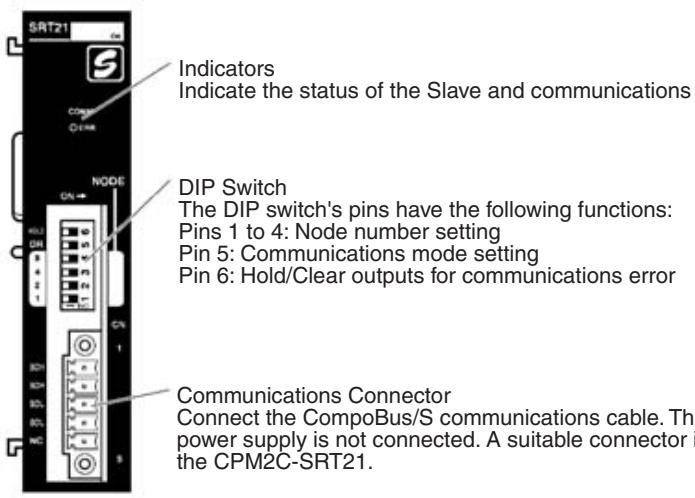
Indicators
The following table shows the meaning of the indicators.
| Indicator | Name | Status | Meaning |
| COMM (yellow) | Communications | ON | Normal communications |
| OFF | A communications error has occurred or the Unit is in standby status. | ||
| ERR (red) | Communications error | ON | A communications error has occurred. |
| OFF | Normal communications or the Unit is in standby status. |
DIP Switch
Always turn OFF the CPM2C CPU Unit before changing DIP switch settings.
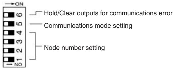
Note Always turn OFF the power supply to the CPM2C before setting the DIP switch.
Node Number Setting
Set the node number with 1 through 4, as shown in the following table.
| Node number | SW4 (8) | SW3 (4) | SW2 (2) | SW1 (1) | Node number | SW 4 (8) | SW 3 (4) | SW2 (2) | SW1 (1) |
| 0 | OFF | OFF | OFF | OFF | 8 | ON | OFF | OFF | OFF |
| 1 | OFF | OFF | OFF | ON | 9 | ON | OFF | OFF | ON |
| 2 | OFF | OFF | ON | OFF | 10 | ON | OFF | ON | OFF |
| 3 | OFF | OFF | ON | ON | 11 | ON | OFF | ON | ON |
| 4 | OFF | ON | OFF | OFF | 12 | ON | ON | OFF | OFF |
| 5 | OFF | ON | OFF | ON | 13 | ON | ON | OFF | ON |
| 6 | OFF | ON | ON | OFF | 14 | ON | ON | ON | OFF |
| 7 | OFF | ON | ON | ON | 15 | ON | ON | ON | ON |
Note
- All 8 input and 8 output points use the same node number.
- The actual node number setting range depends on the PLC model in which the Master is mounted as well as the Master's settings. Refer to 2-1 Communications Specifications for details.
Communications Mode Settings
The following communications modes are set with pin 5 of the DIP switch.
| Pin 5 (DR) | Communications mode | Communications distance | Communications baud rate | Communications cycle time |
| OFF | High-speed Communications Mode | 100 m max. | 750 kbps | 0.5 or 0.8 ms |
| ON | Long-distance Communications Mode | 500 m max. | 93.75 kbps | 4.0 or 6.0 ms |
Note
- Only the C200HW-SRM21-V1, CQM1-SRM21-V1, SRM1-CO□-V2, and CPM2C-S Master Units can be Long-distance Communications Mode.
- Make sure that the communications mode of the Slave is the same as that of the Master Unit. If the communications modes are not the same, normal communications with the Master Unit will not be possible. The operating status of the Slave can be verified with LED indicators. Refer to 6-5-1 Indicators for details.
Hold/Clear Outputs for Communications Error
Pin 6 is used to set the output data status when a communications error occurs, as shown in the following table.
| Pin 6 (HOLD) | Setting |
| OFF | Clear output status |
| ON | Maintain output status |
Terminal Arrangement and Wiring
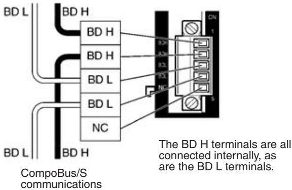
CompoBus/S communications
When viewed from the CPM2C CPU Unit, the 8 input and 8 output points under the CompoBus/S I/O Link Unit are allocated to the I/O memory (input and output bits) of the CPU Unit, as is the case with Expansion I/O Units. One input and one output words are allocated. Actual I/O operations are not performed for the I/O memory of the CPM2C CPU Unit, but it is performed for the
I/O Memory of the CPU Unit in which the CompoBus/S Master Unit is mounted.
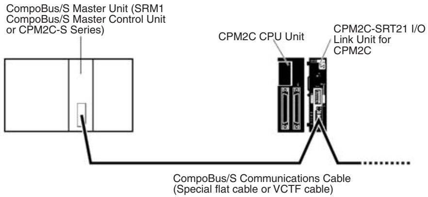
Allocation to CPM2C I/O Bits
As with other Expansion I/O Units for the CPM2C, both input and output bits for the I/O Link Unit start with the word following the last word allocated to the CPM2C CPU Unit or the previous Expansion I/O Unit to which it is connected. If the last input word allocated to the CPM2C CPU Unit or the previous Expansion Unit is word m, and the last output word allocated to that Unit is word n, word allocations are as shown in the following figure.
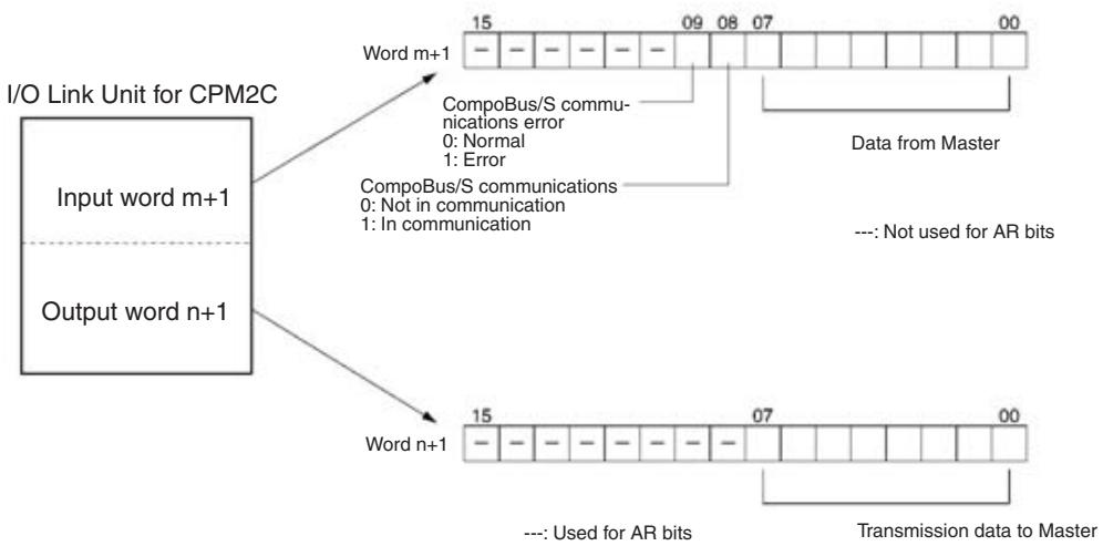
An I/O Link Unit for the CPM2C Series can be connected to the first 20-point I/ O CPM2C CPU Unit as shown in the following figure.
| CPU Unit (with 20 I/O points) | Input number IR 000 | Input number IR 001 | CPM2C-SRT21 I/O Link Unit for CPM2C |
| Output number IR 010 | Output number IR 011 |
Note
- Data transmissions are not synchronized for all 8 I/O points. Eight-point data simultaneously output from the Master CPU will not always reach the CPM2C CPU Unit simultaneously. Eight-point data simultaneously output from the CPM2C CPU Unit will not always reach the CPU Unit of the Master simultaneously. If 8-point data needs synchronization, write the ladder
program to read the data twice consecutively on the input side and treat the data as valid data only if the same data is read both times.
- Output bits allocated to the I/O Link Unit for CPM2C but not used for data output can be used as work bits.
- Allocated input bits cannot be used as work bits regardless of the input bits are used for data input or not.
Allocation to Master CPU Unit
The 8 input and 8 output points allocated to the I/O memory of the CPM2C CPU Unit will be allocated in the Special I/O Unit data area of the Master CPU Unit according to the node number. Both 8 input and 8 output points use the same node number. For example, if the range of node numbers IN0 to IN7 and OUT0 to OUT7 is set, and node number 0 is used, data will be input from bits 00 to 07 of word n (Output Slave 0) and output to bits 00 to 07 of word n + 4 (Input Slave 0).
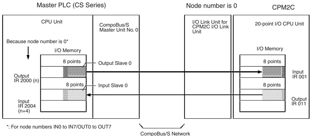
Note Input word bits 08 and 09 of the CPM2C CPU Unit are used by the I/O Link Unit for CPM2C. As an Output Slave of the Master CPU Unit, only 8 points are allocated.
5-11 Sensor Amplifier Terminals
5-11-1 SRT1-T□D04S Sensor Amplifier Terminals
Combinations
| Sensor Amplifier Communications Terminals Connector Units (1 Channel Input) | ||||
| Input | Model | Input | Specifications | Model |
| 4 input points (1 channel × 4 units) | SRT1-TID04S | E3X-N Connector | General-purpose, 1 channel | E3X-NT16 |
| 4 input points (4 channels × 1 unit) | SRT1-TKD04S | Multi-function, 1 channel | E3X-NT26 | |
| Terminal Block Unit | 1 input point | E39-JID01 | ||
| + | ||||
| Sensor Amplifier Expansion Terminals Connector Unit (4 Channels Input) | ||||
| Input | Model | Input | Specifications | Model |
| 4 input points (1 channel × 4 units) | SRT1-XID04S | E3X-N Connector | Multi-function, 1 channel | E3X-NM16 |
| 4 input points (4 channels × 1 unit) | SRT1-XKD04S | |||
Specifications
The following tables show the ratings and specifications for the SRT1-T□D04S.
Sensor Amplifier Terminals
| Item | Specification | |||
| SRT1-TID04S | SRT1-TKD04S | SRT1-XID04S | SRT1-XKD04S | |
| Classification | Communications | Expansion | ||
| Connected Sensors | Total of four E3X-NT□6 or E39-JID01 (see note 1) | One E3X-NM16 (see note 1) | Total of four E3X-NT□6 or E39-JID01 | One E3X-NM16 |
| Input points (see note 2) | 4 points | |||
| Communications mode | High-speed communications mode only | --- | ||
| Power supply type | Network power supply | --- | ||
| Communications power supply voltage | 14 to 26.4 V DC (see note 3) | --- | ||
| Current consumption | 60 mA max. (see note 4) | 10 mA max. (see note 4) | ||
| Noise immunity | ±1.5 kVp-p with a pulse width of 0.1 to 1 μs and a rise time of 1 ns (via impulse noise simulator) | |||
| Vibration resistance | 10 to 55 Hz, 1.5-mm double amplitude | |||
| Shock resistance | 200 m/s2 | |||
| Dielectric strength | 500 V AC (between insulated circuits) | |||
| Ambient temperature | Operating: 0 to 55°C (with no icing or condensation) Storage: -20 to 65°C (with no icing or condensation) | |||
| Ambient humidity | Operating: 35% to 85% (with no condensation) Storage: 25% to 85% (with no condensation) | |||
| Mounting method | M4 screws or 35-mm DIN track mounting | |||
| Mounting strength | 49 N in each direction. Track direction: 10 N | |||
| Terminal strength | Pulling: 49 N Tightening: 0.6 to 1.18 N·m | |||
| Node number settings | The node number is set on a DIP switch. (Set the node number before turning ON the Slave.) | |||
| Weight | 70 g max. | 65 g max. | 45 g max. | 35 g max. |
Note
- When adding Connector Units, use SRT1-XID04S or SRT1-XKD04S.
- The Sensor Amplifier Terminal is treated as a Slave with four input points if the Sensor Amplifier Communications Terminal is used alone. The combination of Sensor Amplifier Communications Terminal and Sensor Amplifier Expansion Terminal are treated as a Slave with eight input points.
- The communications power supply voltage must be 20.4 to 26.4 V DC if the Terminal is connected to 2-wired proximity sensors.
- The value doesn't include the current consumption of Connector Units.
Connector Units
E3X-N Connector Unit
| Item | Specification | ||
| E3X-NT16 | E3X-NT26 | E3X-NM16 | |
| Amplifier | General-purpose | Multi-function | |
| Number of fiber inputs | 1 channel | 4 channels | |
| Current consumption | 50 mA max. | 150 mA max. | |
| Response time | 500 μs max. (2.0 ms max. when connected to the SRT1-□□D04S) | ||
| Timer function | Not available | OFF-delay timer (fixed to 40 ms) | |
| Indicators | Orange LED: Lit during output operation Green LED: Lit with stable light reception or no light | ||
| Teaching confirmation function | Indicators (red/green LED) and buzzer | ||
| Output | Light ON and Dark ON (switch selectable) | ||
| Ambient illumination | Sunlight:10,000 lux max.; incandescent lamp: 3,000 lux max. | ||
| Insulation resistance | 20 MΩ min. at 500 V DC | ||
| Dielectric strength | 1,000 V AC at 50/60 Hz | ||
| Vibration resistance | Destruction: 10 to 55 Hz, 1.5-mm double amplitude | ||
| Shock resistance | Destruction: 500 m/s² | ||
| Ambient temperature | Operating: 0 to 55°C (with no icing or condensation) Storage: -20 to 65°C (with no icing or condensation) | ||
| Ambient humidity | Operating: 35% to 85% (with no condensation) Storage: 25% to 85% (with no condensation) | ||
| Mounting method | Connected to SRT1-□□D04S | ||
| Mounting strength | 49 N in each direction. | ||
| Weight | 30 g max. | 30 g max. | 60 g max. |
Terminal Block Unit
| Item | Specification |
| Model | E39-JID01 |
| Input points | 1 point |
| Input current | 10 mA max. |
| ON voltage | 12 V DC min. (between input terminal and external sensor power supply) |
| OFF voltage | 4 V DC max. (between input terminal and external sensor power supply) |
| OFF current | 1 mA max. |
| ON delay time | 1 ms max. (connected to SRT□-□□D04S) |
| OFF delay time | 1.5 ms max. (connected to SRT□-□□D04S) |
| Input indicators | LED (orange) |
| External sensor current capacity | 50 mA max. |
| Vibration resistance | 10 to 55 Hz, 1.0-mm double amplitude |
| Shock resistance | 200 m/s² (approx. 20G) |
| Ambient temperature | Operating: 0 to 55°C (with no icing or condensation) Storage: -20 to 65°C (with no icing or condensation) |
| Ambient humidity | Operating: 35% to 85% (with no condensation) Storage: 25% to 85% (with no condensation) |
| Mounting method | M4 screws or 35-mm DIN track mounting |
| Mounting strength | 49 N in each direction. (But only 10 N in direction of track.) |
| Terminal strength | Pulling: 49 N Tightening: 0.6 to 1.18 N·m |
| Weight | 25 g max. |
Slave Components
The following diagram shows the main components of the Sensor Amplifier Terminals. The functions of these components are described below.
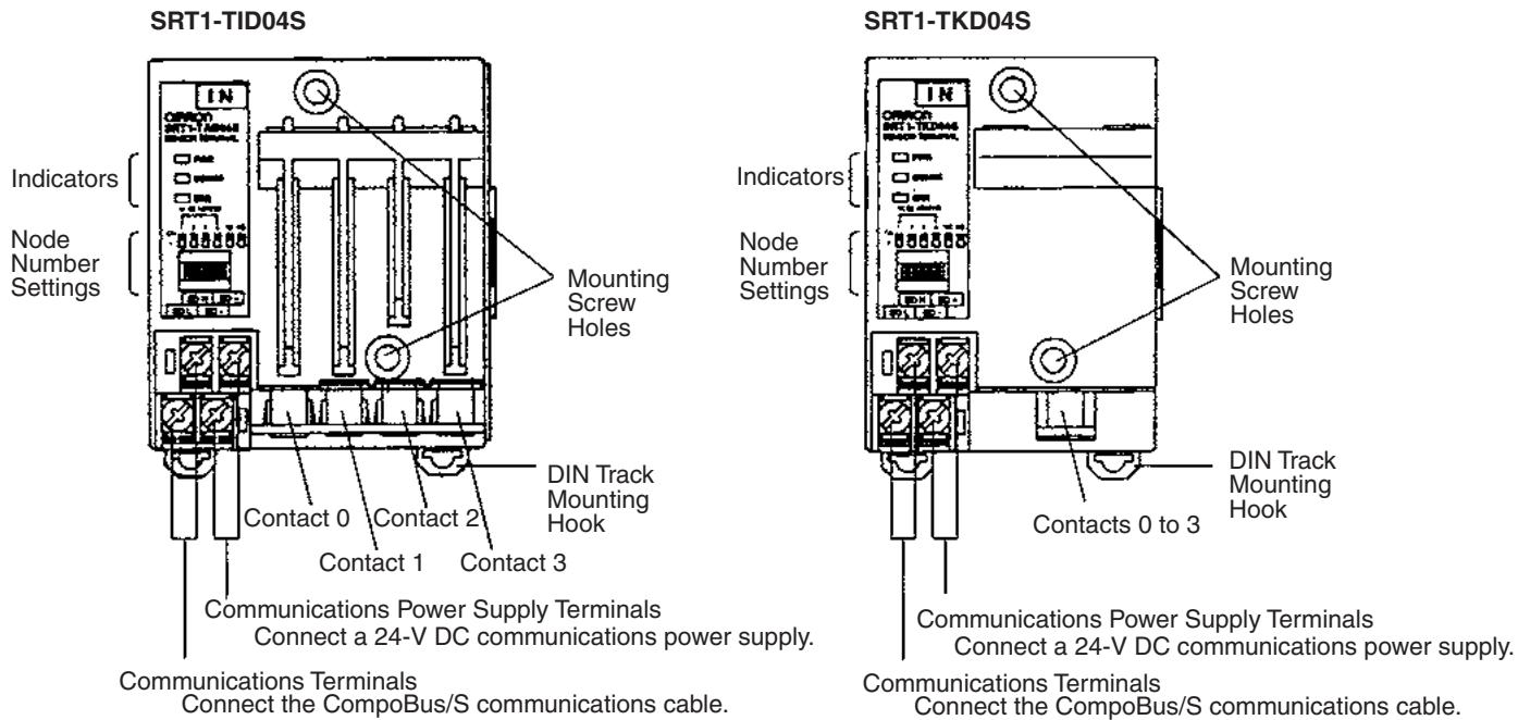
Indicators
The following table shows the meaning of the indicators.
| Indicator | Name | Status | Meaning |
| PWR (green) | Power | ON | The communications power supply is ON. |
| OFF | The communications power supply is OFF. | ||
| COMM (yellow) | Communications | ON | Normal communications. |
| OFF | A communications error has occurred or the Unit is in standby status. | ||
| ERR (red) | Communications error | ON | A communications error has occurred. |
| OFF | Normal communications or the Unit is in standby status. |
DIP Switch
Always turn OFF the Slave before changing DIP switch settings.
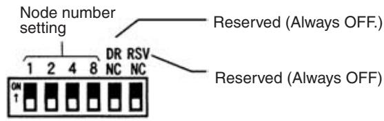
Note 1. Always turn OFF the Slave before changing DIP switch settings.
2. Pins 5 and 6 must always be left OFF. Otherwise, the Unit may not function correctly.
Node Number Settings
Set the node number with pins 1 through 8, as shown in the following table.
| Node number | Pin 1 (1) | Pin 2 (2) | Pin 4 (4) | Pin 8 (8) |
| 0 | OFF | OFF | OFF | OFF |
| 1 | ON | OFF | OFF | OFF |
| 2 | OFF | ON | OFF | OFF |
| 3 | ON | ON | OFF | OFF |
| 4 | OFF | OFF | ON | OFF |
| 5 | ON | OFF | ON | OFF |
| 6 | OFF | ON | ON | OFF |
| 7 | ON | ON | ON | OFF |
| 8 | OFF | OFF | OFF | ON |
| 9 | ON | OFF | OFF | ON |
| 10 | OFF | ON | OFF | ON |
| 11 | ON | ON | OFF | ON |
| 12 | OFF | OFF | ON | ON |
| 13 | ON | OFF | ON | ON |
| 14 | OFF | ON | ON | ON |
| 15 | ON | ON | ON | ON |
Note The actual node number setting range depends on the type of PLC in which the Master is mounted as well as the Master's settings. Refer to 2-1 Communications Specifications for details.
Internal Circuits
The following diagram shows the internal circuits for the E39-JID01.
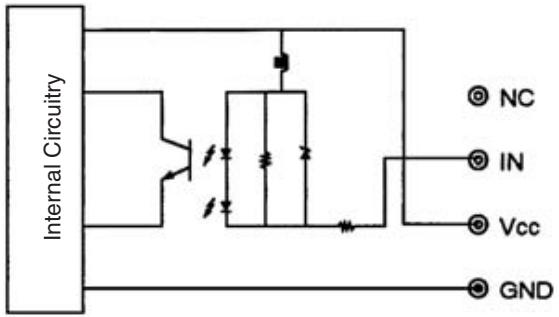
Terminal Arrangement and Wiring
The following diagram shows the terminal arrangement and wiring for the E39-JID01.
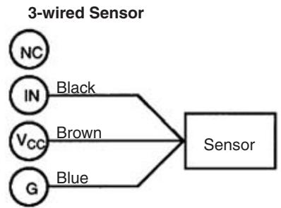
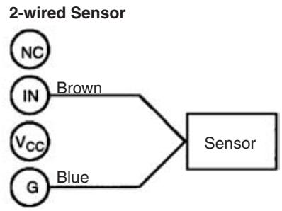
Dimensions
Sensor Amplifier Terminals
- SRT1-TID04S Sensor Amplifier Terminals (1 Channel × 4 Units) All dimensions are in mm.
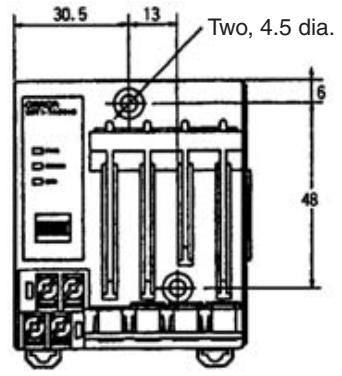
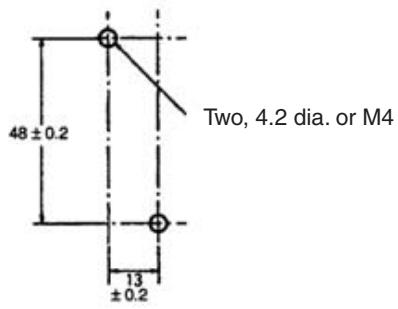
Mounting Holes
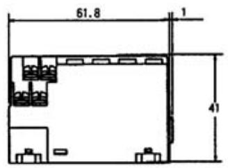
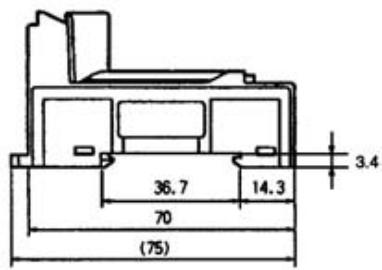
- SRT1-XID04S Sensor Amplifier Expansion Terminal (1 Channel × 4 Units) All dimensions are in mm.
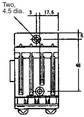
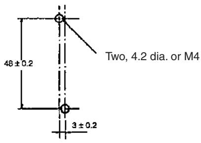
Mounting Holes
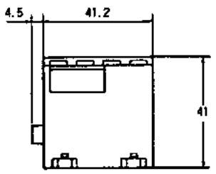
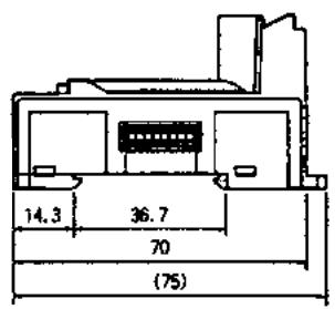
- SRT1-TKD04S Sensor Amplifier Terminal (4 Channels × 1 Unit) All dimensions are in mm.
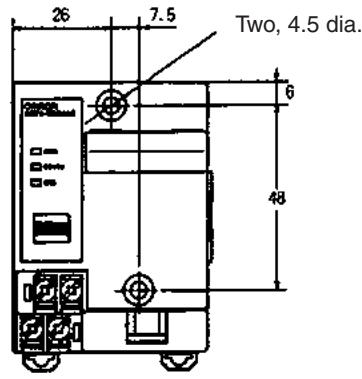
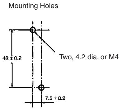
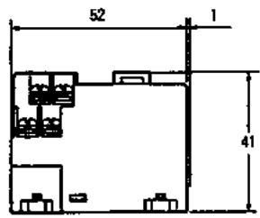
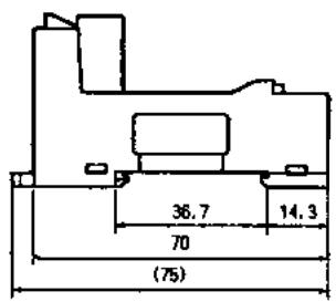
- SRT1-XKD04S Sensor Amplifier Expansion Terminal (4 Channels × 1 Unit) All dimensions are in mm.

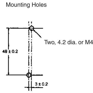
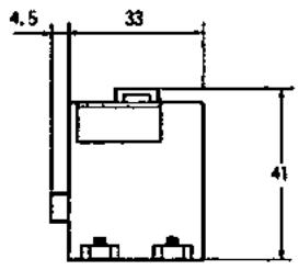
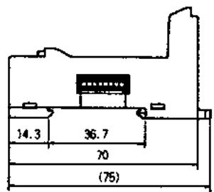
Connector Units
- E3X-NT□6 Connector (General-purpose or Multi-function, 1 Channel) All dimensions are in mm.
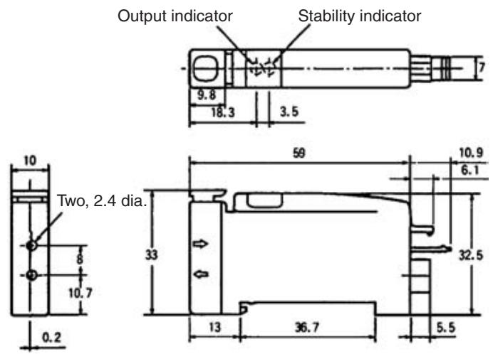
- E3X-NM16 Connector (Multi-function, 4 Channels) All dimensions are in mm.
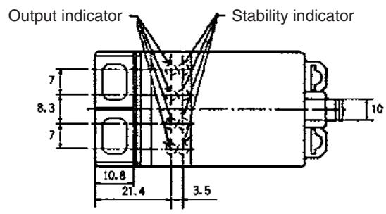
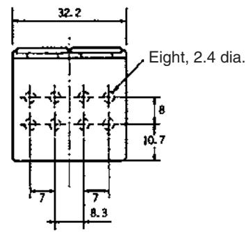
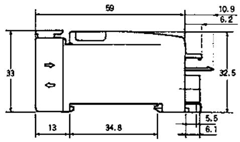
- E39-JID01 Terminal Block Unit (1 Input Point) All dimensions are in mm.
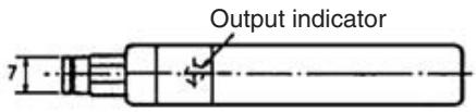
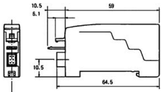
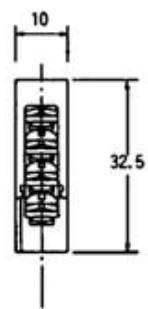
5-11-2 Sensor Amplifier Terminals
Attaching and Removing Connector Units
1 Channel × 4 Units
| Sensor Amplifier Terminal | Connector Unit |
| SRT1/SRT2-TID04S | E3X-NT16 |
| SRT1/SRT2-XID04S | E3X-NT26 |
| E39-JID01 |
Attaching Connector Units:
1,2,3... 1. Hook Section A of the Connector Unit onto Section B of the Sensor Amplifier Terminal.
- Push in the Connector Unit until Section C locks inside Section D of the Sensor Amplifier Terminal.
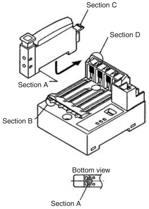
Removing Connector Units:
1,2,3... 1. While pushing Section D, pull the Connector Unit in direction E.
- When Section D releases from the lock, the Connector Unit can be removed.
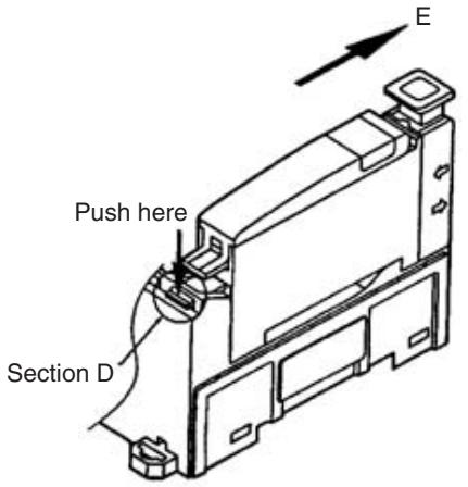
4 Channels × 1 Unit
| Sensor Amplifier Terminal | Connector Unit |
| SRT1/SRT2-TKD04S | E3X-NM16 |
| SRT1/SRT2-XKD04S |
Attaching Connector Unit:
1,2,3... 1. Hook Section A of the Connector Unit onto Section B of the Sensor Amplifier Terminal.
- Push in the Connector Unit until Section C locks inside Section D of the Sensor Amplifier Terminal.
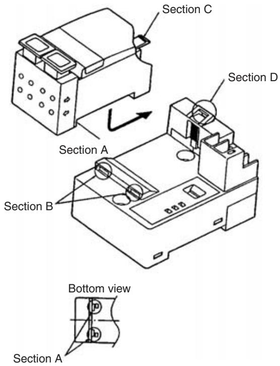
Removing Connector Unit:
1,2,3... 1. While pushing Section D, pull the Connector Unit in direction E.
- When Section D releases from the lock, the Connector Unit can be removed.
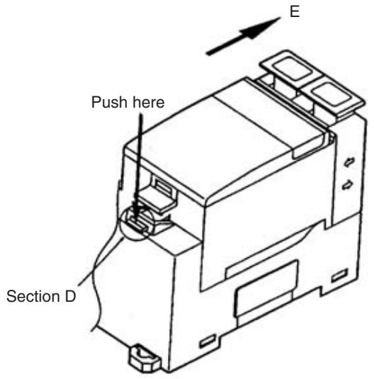
Expanding Sensor Amplifier Terminals
1,2,3... 1. Remove the cover from the side of the SRT-T-D04S. When the cover is removed, the expansion connector can be seen inside.
- Connect this expansion connector to the connector located on the side of the SRT- X D04S.
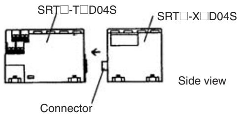
Removing Contact Connector Cover
Contacts 1 through 3 of the SRT□-TID04S are covered with a contact connector cover. When using these contacts, refer to the following figure and pull out and remove Section A of the contact connector cover in the direction of its end.
E3X-N Connectors
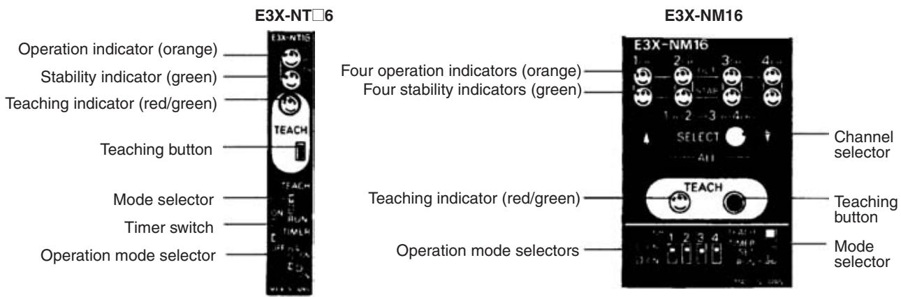
Note The E3X-NT16 does not have a timer function.
Optical Axis Adjustment (Super-flashing Function)
Set the mode selector of the E3X-N□ to TEACH. The super-flashing function of the E3X-N□ will be activated. When the optical axes of the fiber heads are divergent and the light value decreases by approximately 10% of the maximum value, the tip of the emitting fiber will start flashing and the built-in buzzer will beep. At this time, if the optical axes are divergent, adjust the axes. The peak light value will be memorized by the E3X-N□. Do not press the teaching button before or while adjusting the optical axes, otherwise, the super-flashing function will not operate.
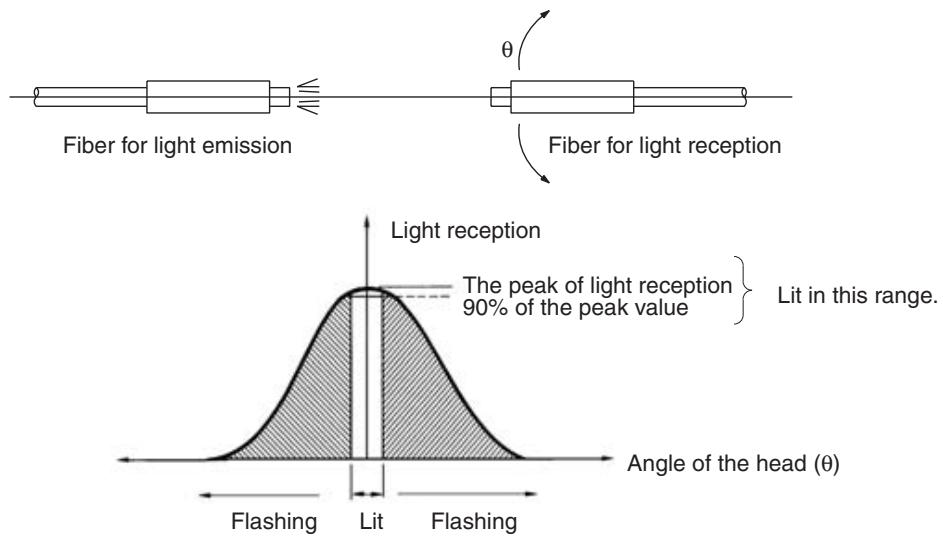
Sensitivity Settings
Maximum Sensitivity Setting
| Procedure | Operation | E3X-NT | E3X-NM |
| 1 | Locate the sensor head within the rated sensing range with the E3X-N□. | ||
| 2 | Set the mode selector to TEACH. | TEACH RUN | TEACH- TIMER SET RUN |
| 3 | The super-flashing function of the E3X-N□ will be activated. Therefore, adjust the optical axes so that the tip of the emitting fiber will be lit. If the optical axes are divergent, the tip of the emitting fiber will flash and the built-in buzzer of the E3X-N□ will beep. | --- | |
| 4 | Press the teaching button for three seconds minimum with or without a sensing object. In the case of the E3X-NM, select a channel with the channel selector, at which time the stability indicator for the selected channel will flash. The teaching indicator (red) turns green. The built-in buzzer beeps once when the color of the teaching indicator is red. The built-in buzzer beeps continuously when the color of the teaching indicator is green. Note: The built-in buzzer will stop beeping when the teaching button is no longer being pressed. | TEACH | TEACH |
| 5 | Set the mode selector to RUN to complete the sensitivity setting. The teaching indicator is OFF. Note: When the sensitivity is set to maximum, the sensitivity will be automatically adjusted regardless of the set distances of the fibers or light. | TEACH RUN | TEACH TIMER SET RUN |
| 6 | Select the logical output required with the operation mode selector. | LON ON | CH 1 2 3 4 LON - D ON - |
No-object Teaching
| Procedure | Operation | E3X-NT | E3X-NM |
| 1 | Locate the sensor head within the rated sensing range with the E3X-N□. | ||
| 2 | Set the mode selector to TEACH. | TEACH RUN | TEACH TIMER SET RUN |
| 3 | The super-flashing function of the E3X-N□ will be activated. Therefore, adjust the optical axes so that the tip of the emitting fiber will be lit. If the optical axes are divergent, the tip of the emitting fiber will flash and the built-in buzzer of the E3X-N□ will beep. | --- | |
| 4 | Press the teaching button for 0.5 to 2.5 seconds without a sensing object. In the case the E3X-NM, select a channel with the channel selector and press the teaching button, at which time the stability indicator for the selected channel will flash. The teaching indicator (red) is lit. The built-in buzzer beeps once. | TEACH RUN | TEACH TIMER SET RUN |
| 5 | Set the mode selector to RUN. No-object teaching will be set when the first sensing object passes through the sensing area. The teaching indicator (red) turns green (automatically turned off in one second). | TEACH RUN | TEACH TIMER SET RUN |
| 6 | Select the logical output required with the operation mode selector. | L ON D ON | CH 1 2 3 4 L ON D ON |
Note 1. After no-object teaching is performed, the first to fifth incident with the corresponding sensing objects will be sampled to adjust the sensitivity.
2. The E3X-N□ will be ready to detect objects in approximately one second after the mode selector is set to RUN.
With/Without-object Teaching
| Procedure | Operation | E3X-NT | E3X-NM |
| 1 | Locate the sensor head within the rated sensing range with the E3X-N□. | --- | |
| 2 | Set the mode selector to TEACH. | TEACH RUN | TEACH- TIMER SET RUN |
| 3 | The super-flashing function of the E3X-N□ will be activated. Therefore, adjust the optical axes so that the tip of the emitting fiber will be lit. If the optical axes are divergent, the tip of the emitting fiber will flash and the built-in buzzer of the E3X-N□ will beep. | --- | |
| Procedure | Operation | E3X-NT | E3X-NM | ||
| 4 | Locate a sensing object in the sensing area and press the teaching button once. In the case of the E3X-NM, select a channel with the channel selector and press the teaching button, at which time the stability indicator for the selected channel will flash. Through-beam Model Light is interrupted. The teaching indicator (red) is lit. The built-in buzzer beeps once. | TEACH | TEACH | ||
| 5 | Move the object and press the teaching button. Through-beam Model Light is received. If teaching is OK: The teaching indicator (red) turns green. The built-in buzzer beeps once. If teaching is NG: The teaching indicator (red) starts flashing. The operation indicator also starts flashing. (E3X-NM) The built-in buzzer beeps 3 times. Change the position of the object and the sensing distance that have been set and repeat from the beginning. | TEACH | TEACH | ||
| 6 | Set the mode selector to RUN to complete the sensitivity setting. The teaching indicator (green) is OFF. | TEACH RUN | TEACH TIMER SET RUN | ||
| 7 | Select the logical output required with the operation mode selector. | LON ON | CH 1 LON 2 3 4 D ON | ||
5-12 Application Precautions
5-12-1 Two-wire DC Sensor Connections
When connecting a Unit with transistor inputs to a 2-wire DC sensor, check that the following conditions are satisfied, or otherwise the Unit may malfunction.
Relationship between ON Voltage of Unit with Transistor Inputs and Residual Voltage of Sensor
$$ V _ {O N} \leq V _ {C C} - V _ {R} $$
V_CC : I/O power supply voltage (calculated at 20.4 V in consideration of the worst condition through the power supply voltage range is between 20.4 and 26.4 V.)
V_ON : ON voltage of Unit with transistor inputs (Refer to page 351 for specifications for each Slave.)
V_R Output residual voltage of sensor
The above formula can be satisfied by setting the I/O power supply voltage (V_CC) to 26.4V .
Relationship between ON Current of Unit with Transistor Inputs and Control Output (Load current) of Sensor
$$ I _ {O U T} (\min ) \leq I _ {O N} \leq I _ {O U T} (\max ) $$
I_OUT :Sensor control output (Load current)
I_ON : ON current of Unit with transistor inputs
I_ON is obtained from the following formula.
$$ I _ {O N} = \left(V _ {C C} - V _ {R} - V _ {F}\right) / R _ {I N} $$
V_F : Residual voltage of Transistor Input (Refer to page 351 for specifications for each Slave.)
R_IN : Input impedance of Unit with transistor inputs (Refer to page 351 for specifications for each Slave.)
If I_ON is smaller than I_OUT (min), connect the bleeder resistance R obtained from the following formula.
$$ R \leq \left(V _ {C C} - V _ {R}\right) / \left(I _ {O U T} (\min ) - I _ {O N}\right) $$
Power W ≥ (V_CC - V_R)^2 / R × 4 (Excess gain)
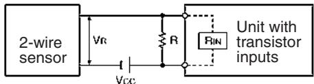
Relationship between OFF Current of Unit with Transistor Inputs and Current Leakage of Sensor
$$ I _ {O F F} \geq I _ {l e a k} $$
I_OUT : OFF current of Unit with transistor inputs (Refer to page 351 for specifications for each Slave.)
leak: Current leakage of sensor
If I_leak is smaller than I_OUT , connect the bleeder resistance R obtained from the following formula.
$$ R \leq \left(I _ {O F F} \times R _ {I N} + V _ {F}\right) / \left(I _ {l e a k} - I _ {O F F}\right) $$
Power W ≥ (V_CC - V_R)^2 / R × 4 (Excess gain)
Specifications of each Slave
The following table shows specifications of each Slave: The ON voltage, residual voltage, input impedance, and OFF current.
| Model | ON voltage (VON) | Residual voltage (VF) | Input impedance (RIN) | OFF current (IOUT) |
| SRT□-ID04/08/16 (-1) | 15 V | 2.5 V (See note.) | 4.7 kΩ | 1.0 mA |
| SRT□-ID16T/MD16T (-1) | 15 V | 1.5 V | 4.4 kΩ | 1.0 mA |
| SRT2-VID08S (-1) | 15 V | 1.5 V | 4.4 kΩ | 1.0 mA |
| SRT2-VID16ML (-1) | 15 V | 1.5 V | 4.4 kΩ | 1.0 mA |
| SRT2-ID32ML (-1) | 15 V | 1.5 V | 4.4 kΩ | 1.0 mA |
| SRT2-MD32ML (-1) | 15 V | 1.5 V | 4.4 kΩ | 1.0 mA |
| SRT□-ID08S | 12 V | 4.5 V (See note.) | 2.7 kΩ | 1.0 mA |
| SRT□-ND08S | 12 V | 4.5 V (See note.) | 2.7 kΩ | 1.0 mA |
| SRT2-ID04CL (-1) | 15 V | 1.5 V | 4.4 kΩ | 1.0 mA |
| SRT2-ID08CL (-1) | 15 V | 1.5 V | 4.4 kΩ | 1.0 mA |
Note The value includes the voltage drop resulting from the LEDs and diodes.
5-12-2 Sensor Inrush Current
When the sensor ready to input is turned ON after the PLC is turned ON and the internal power supply of a Slave is turned ON, the wrong signal may be input from the sensor due to the inrush current of the sensor. Check the period between the moment the sensor is turned ON and the moment the operation of the sensor has become stable. Then program a timer delay after the sensor is turned ON.
Program example
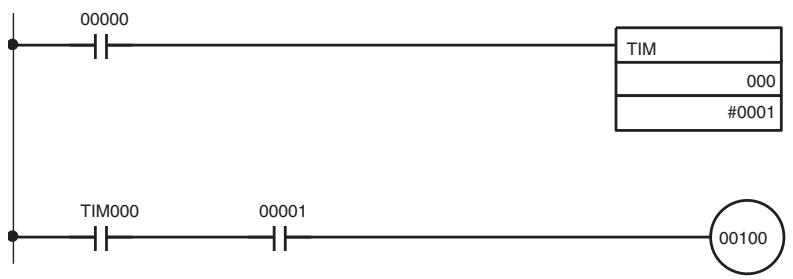
1,2,3... 1. Set input bit IR 00000 to the sensor power supply voltage.
- Insert a timer delay for the stabilization of the sensor. The delay will be 100 ms if OMRON's Proximity Sensor is used.
- After the timer is ON, sensor input to input bit IR 00001 is accepted and output bit IR 00100 will be ON.
SECTION 6
Starting Communications
This section provides information on error processing, periodic maintenance operations, and troubleshooting procedures needed to keep the CompoBus/S System operating properly.
6-1 Turning the Power ON 354
6-1-1 Power-up Checklist. 355
6-2 Checking Operations for CS-series, C200HX/C200HG/C200HE-(Z)E, and C200HS Master Units 356
6-2-1 Indicators 356
6-2-2 Checking Status Using Status Information. 357
6-2-3 Checking Normal Operations Using Ladder Programs 359
6-2-4 Troubleshooting 360
6-3 Checking Operations of CS-series and CJ-series Master Units 365
6-3-1 Indicators 365
6-3-2 Checking Status Using Status Information. 365
6-3-3 Checking Status Using Special I/O Unit DM Area 367
6-3-4 Checking Normal Operations Using Ladder Programming 371
6-3-5 Troubleshooting 373
6-4 Checking Operations of CQM1 Master Units. 377
6-4-1 Indicators 377
6-4-2 Error Detection with the Alarm Output (CQM1 Only) 378
6-4-3 Checking Normal Operations Using Ladder Programming 379
6-4-4 Troubleshooting 379
6-5 Checking Slave Operations 382
6-5-1 Indicators 382
6-6 Cleaning and Inspection 384
6-6-1 Cleaning 384
6-6-2 Inspection 384
6-7 Precautions for Replacement of Units or Parts 385
6-7-1 Precautions for Unit Replacement 385
6-7-2 Settings after Unit Replacement 385
6-7-3 Replacing Relays 385
6-1 Turning the Power ON
Once all of the connections and settings have been made, power can be supplied to all of the Units in the CompoBus/S System and communications can be started.
Caution Power Connections
Be sure to check the power supply connections carefully before turning the power ON. Incorrect wiring can damage the Units in the system or cause them to malfunction.
Required Settings
The settings required for CompoBus/S I/O data communications are the Master Unit switch settings, the node number setting, and the communications mode setting on each Slave Unit. Depending on the Slaves being used, other settings such as holding or clearing outputs for communications errors may be required. Refer to SECTION 4 Master Unit Specifications and Operations and SECTION 5 Slave Specifications and Operations for details.
Before turning ON the power, check the settings and wiring, referring to 3-5 Operations Checklist.
Turning the Power ON
The Units in a CompoBus/S System can be turned ON in any order. Turn ON the power to the Slaves first, however, to enable communications to start at the same time that the Master Unit is started up. The following table shows which Units are supplied by each power supply.
| Unit | Required power supply |
| Master | PLC's power supply |
| Network power supply Slave | Communications power supply (including the I/O power supply) |
| Dual power supply Slave | Communications power supply and I/O power supply |
| Local power supply Slave | Slave power supply |
CompoBus/S communications will start up automatically once the required power has been supplied to all of the Units.
Note
- An error will not occur if the Slave has the same node number setting as another Unit. Use the status area in the Master Unit to detect for Slaves that have the same node number.
- When the Slave registration function is used with a CS-series or CJ-series Master Unit, the Slaves start to be checked after the Master has been started up and the registered Slave input monitoring time has lapsed. When Slaves are slow to power up, a verification error (Slave missing) may occur, so check the power-up timing
- When using a CS-series or CJ-series Master Unit, if the Slave registration function is used and the system is started up after being connected and set, incorrect node number settings and Slaves that are missing from the network can be easily checked
6-1-1 Power-up Checklist
After turning the power ON, use the following checklist to verify the CompoBus/S communications have started properly.
| Unit | Check | Answer |
| Master | Are the RUN, SD, and RD indicators lit? | Yes No |
| With CS-series, C200HX/C200HG/C200HE-(Z)E, and C200HS Master Units, is the ERC indicator OFF? | Yes No | |
| With CS-series Master Units, are the ERH and ERC indicators OFF? | Yes No | |
| With CJ-series Master Units, are the ERH and ERC indicators OFF? | Yes No | |
| With a CS-series, C200HX/C200HG/C200HE-(Z)E, and C200HS Master Unit, CS-series Master Unit, or CJ-series Master Unit, are the Active Node Flags ON for all of the Slaves connected to the system? | Yes No | |
| With CQM1 Masters, are the ERS and ERC indicators OFF? | Yes No | |
| Slave | Are the PWR and COMM indicators lit? | Yes No |
| Is the ERR indicator OFF? | Yes No | |
| Is the U.ERR indicator OFF? (For SRT2-AD04 and SRT2-DA02 Analog Terminals only) | Yes No |
Note
- If any questions are answered "No," refer to 6-2 Checking Operations for CS-series, C200HX/C200HG/C200HE-(Z)E, and C200HS Master Units to 6-5 Checking Slave Operations for instructions on identifying and clearing the cause of the error.
- For SRM1 and CPM2C-S Master Units, refer to the SRM1 Operation Manual and CPM2C-S Operation Manual.
6-2 Checking Operations for CS-series, C200HX/C200HG/ C200HE-(Z)E, and C200HS Master Units
6-2-1 Indicators
Errors and Troubleshooting
| Situation | Indicator status | Probable cause | Possible remedy | |||
| RUN | ERC | SD | RD | |||
| Normal communications | ON | OFF | ON | ON | --- | --- |
| PLC's power OFF | OFF | OFF | OFF | OFF | The PLC's power is OFF. | Turn the PLC's power supply ON. |
| Not connected to Backplane | OFF | OFF | OFF | OFF | The Master is not completely connected to the Backplane. | Mount the Master properly. |
| CPU Unit standby status | OFF | OFF | OFF | OFF | One of the Special I/O Units is faulty. | Replace the faulty Unit, which will be indicated by a“$” in the I/O table. |
| Special I/O Unit error | OFF | OFF | OFF | OFF | Refreshing between the PLC and Master Unit is not being performed properly. | After correcting the cause, toggle the Unit's restart bit in the AR Area. Replace the Unit if it doesn't reset when the restart bit is toggled. |
| I/O UNIT OVER error | OFF | OFF | OFF | OFF | The same unit number has been set on two or more Special I/O Units. An out-of-range unit number has been set. | Set unique unit numbers. If the usable node numbers are within IN0 to IN15 and OUT0 to OUT15, 9 or F cannot be set. node numbers A to F cannot be used with C200HX-CPU3□-(Z)E/ -CPU4□-(Z)E, C200HG-CPU3□-(Z)E/ -CPU4□-(Z)E, or C200HS PLCs. |
| I/O BUS error | OFF | OFF | OFF | OFF | The I/O bus is not connected correctly. (In CS-series PLCs, an I/O BUS error may have occurred in another Unit.) | Check the I/O connecting cables between all Racks. Clear the error after the connection is fixed. |
| Slave not connected | ON | OFF | ON | OFF | No Slaves are connected, or the communications mode of each Slave does not match that of the Master Unit. | Use a Slave that can communicate properly, or make the communications mode of each Slave match that of the Master Unit. |
| Communications error with a Slave | ON | ON | ON | --- | An error has occurred with a Slave during communications and it is withdrawn from the system. | Check the Communications Error Flags or indicators and clear the cause of the communications error. See Communications Error Node Number Indicators below. |
Note Check the system's operation with just one Slave connected (one Slave at a time) if the CompoBus system does not operate but the Master's indicator status does not match any of those in the table.
Communications Error Node Number Indicators (C200HW-SRM21-V1 Only)
When a communications error occurs with a Slave during communications and the ERC indicator lights, the other indicators will show the node number of the Slave where the error occurred in binary.
When several communications errors occur simultaneously, the node number of the Slave with the first recognized communications error will be displayed. The display will not be changed if another communications error occurs while a node number is already being displayed. A new node number can be displayed after the first communications error is cleared.
When a communications error occurs in a 16-point or greater Slave, any of the node numbers currently used by that Slave may be displayed.
The following table shows some examples of node number displays.
| Situation | Indicator status | Possible remedy | |||||
| ERC | I/O | 8 | 4 | 2 | 1 | ||
| Communications error in the Input Slave with node number 13 | ON | OFF | ON | ON | OFF | ON | Check the communications cable to Input Slave 13 and the status of the Slave itself. |
| Communications error in the Output Slave with node number 6 | ON | ON | OFF | ON | ON | OFF | Check the communications cable to Output Slave 6 and the status of the Slave itself. |
| Communications error in the Input Slave with node number 0 | ON | OFF | OFF | OFF | OFF | OFF | Check the communications cable to Input Slave 0 and the status of the Slave itself. |
| A communications error occurs in the Output Slave with node number 11 after an error occurs in the Input Slave with node number 3. | ON | OFF | OFF | OFF | ON | ON | First, check the communications cable to Input Slave 3 and the status of the Slave itself. Once the error in Input Slave 3 is cleared, the display will show the error in Output Slave 11 and this error can be cleared. |
6-2-2 Checking Status Using Status Information
When using CS-series, C200HX/C200HG/C200HE-(Z)E, or C200HS Master Units, information on active Slave status and communications error status is stored for each Slave in the status area of the PLC's Special I/O Unit Area.
Status Area Location and Configuration
The location and configuration of the status area is shown in the following table.
Usable Node Number is IN0 to IN7 and OUT0 to OUT7
Two words are used for flags when the max. number of Slaves setting is 16.
| PLC | Location of Status Area |
| CS-series PLCs | First word = 2000 + unit number × 10 |
| C200HX/C200HG/ C200HE-(Z)E, and C200HS PLCs | Unit numbers 0 to 9: First word = 100 + unit number × 10 Unit numbers A to F (10 to 15): First word = 400 + (unit number – 10) × 10 |
| 15 14 13 12 11 10 9 8 | 7 6 5 4 3 2 1 0 |
| Output Slave Communications Error Flags Slave 7-0 | Active Output Slave Flags Slave 7-0 |
| First word + 9 | Input Slave Communications Error Flags Slave 7 | Active Input Slave Flags Slave 7 |
Usable Node Number is IN0 to IN15 and OUT0 to OUT15
Four words are used for flags when the max. number of Slaves setting is 32.
| PLC | Location of Special I/O Unit Area |
| CS-series PLCs | First word = 2000 + unit number × 10 |
| C200HX/C200HG/ C200HE-(Z)E, and C200HS PLCs | Unit numbers 0 to 8: First word = 100 + unit number × 10 Unit numbers A to E (10 to 14): First word = 400 + (unit number - 10) × 10 |
| Bits | |
| 15 14 13 12 11 10 9 8 7 6 5 4 3 2 1 0 | |
| Output Slave Communications Error Flags Slave 7 - - - - - - - - - - - - - - - - - - - - - - - - - - - - - - - - - - - - - - - - - - - - - - - - - - - - - - - - - - - - - - - - - - - - - - - - - - - - - - - - - - - - - - - - - - - - - - - - - - - - | |
| Active Output Slave Flags Slave 7 - - - - - - - - - - - - - - - - - - - - - - - - - - - - - - - - - - - - - - - - - - - - - - - - - - - - - - - - - - - - - - - - - - - - - - - - - - - - - - - - - - - - - - - - - - - - - - | |
| Input Slave Communications Error Flags Slave 7 - - - - - - - - - - - - - - - - - - - - - - - - - - - - - - - - - - - - - - - - - - - - - - - - - - - - - - - - - - - - - - - - - - - - - - - - - - - - - - - - - - - - - - - - - - - | |
| Active Input Slave Flags Slave 7 - - - - - - - - - - - - - - - - - - - - - - - - - - - - - - - - - - - - - - - - - - - - - - - - - - - - - - - - - - - - - - - - - - - - - - - - - - - - - - - - - - - - - - - - - - - - - | |
| Output Slave Communications Error Flags Slave 15 - - - - - - - - - - - - - - - - - - - - - - - - - - - - - - - - - - - - - - - - - - - - - - - - - - - - - - - - - - - - - - - - - - - - - - - - - - - - - - - - - - - - - - - - - - - - - - - - - - - - Active Output Slave Flags Slave 15 - - - - - - - - - - - - - - - - - - - - - - - - - - - - - - - - - - - - - - - - - - - - - - - - - - - - - - - - - - - - - - - - - - - - - - - - - - - - - - - - - - - - - - - - - - - - - | |
| Input Slave Communications Errors Flags Slave 15 - - - - - - - - - - - - - - - - - - - - - - - - - - - - - - - - - - - - - - - - - - - - - - - - - - - - - - - - - - - - - - - - - - - - - - - - - - - - - - - - - - - - - - - - - - - - - Active Input Slave Flags Slave 15 - - - - - - - - - - - - - - - - - - - - - - - - - - - - - - - - - - - - - - - - - - - - - - - - - - - - - - - - - - - - - - - - - - - - - - - - - - - - - - - - - - - - - | |
Status Flag Functions
The status flags have the following functions. These flags are automatically cleared to 0 when the power is turned ON or the system is restarted.
Active Output Slave Flags
These flags indicate whether the corresponding Output Slaves are active nodes in the CompoBus/S communications.
| Flag status | Meaning |
| 0 (OFF) | The corresponding Slave is not participating in communications. (OFF if the Slave didn’t participate even one time.) |
| 1 (ON) | The corresponding Slave is participating in communications. (Not changed even if the Slave is withdrawn from communications.) |
Active Input Slave Flags
These flags indicate whether the corresponding Input Slaves are active nodes in the CompoBus/S communications.
| Flag status | Meaning |
| 0 (OFF) | The corresponding Slave is not participating in communications. (OFF if the Slave didn’t participate even one time.) |
| 1 (ON) | The corresponding Slave is participating in communications. (Not changed even if the Slave is withdrawn from communications.) |
Output Slave Communications Error Flags
These flags indicate whether a communications error has occurred with the corresponding Output Slaves.
| Flag status | Meaning |
| 0 (OFF) | Normal communications or the Slave is not participating in communications. |
| 1 (ON) | Withdrawn from communications (communications error) |
Input Slave Communications Error Flags
These flags indicate whether a communications error has occurred with the corresponding Input Slaves.
| Flag status | Meaning |
| 0 (OFF) | Normal communications or the Slave is not participating in communications. |
| 1 (ON) | Withdrawn from communications (communications error) |
Note Input from Input Slaves and output to Output Slaves are enabled when the CompoBus/S System is started up and the Active Node Flag corresponding to the Slave turns ON. During actual operation, it is recommended to create ladder programming that processes Slave I/O after checking that Active Node Flags are ON and Communications Error Flags are OFF.
6-2-3 Checking Normal Operations Using Ladder Programs
This section provides information on how to write a ladder program to monitor the operation of the CompoBus/S System and prohibit using the I/O data of the Slaves in the system when an error occurs.
To write a ladder program for CompoBus/S remote I/O communications for the CS-series, C200HX, C200HG, C200HE-(Z)E, or C200HS Master Unit, it is recommended to write I/O data on condition that the Active Node Flags and Communications Error Flags in the status area are monitored to check the operation of the CompoBus/S System.
The CompoBus/S status area has the following flags. (Refer to page 81.)
Active Node Flags:
Once a Slave joins the CompoBus/S network after the Slave is turned ON, the Active Node Flag corresponding to the Slave will be ON.
Communications Error Flags:
If a Slave in the network fails to communicate with the Master, the Communications Error Flag corresponding to the Slave will be ON. After the Communications Error Flag is ON, the previous input data from the input Slave will be kept on hold. While the Communications Error Flag is ON, the input date of the input Slave is not reliable. (The program will be executed with the previous data.)
The following ladder program example uses I/O data after checking the normal operation of the CompoBus/S System. In this example, the C200HX Master with unit number 0 is used and usable node numbers are IN0 to IN7 and OUT0 to OUT7.
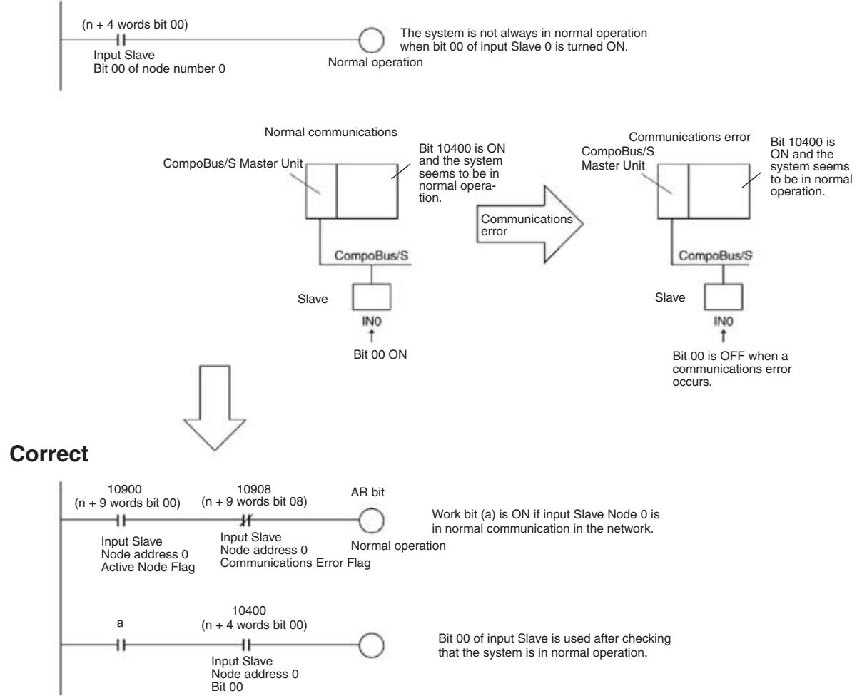
Wrong
It is possible to write a ladder program that confirms normal operation when a work bit (a) turns OFF.
A ladder program that checks all the Active Node Flags and Communications Error Flags in a batch, checks the overall CompoBus/S System operations, and then performs I/O processing for the Slaves in a batch can also be written. For details, refer to the section for CJ-series Master Units under 6-3-4 Checking Normal Operations Using Ladder Programming.
6-2-4 Troubleshooting
When an error occurs, the indicators of a Master Unit connected to a CSeries, C2missing00HX/C200HG/C200HE-(Z)E, or C200HS PLC will indicate the error. Check the Master Unit's indicators and perform the error processing described in the following table.
When an error occurs in a Slave, the Slave can be identified from the status of the Master's indicators or from the status flags in the PLC's Special I/O Unit Area.
| Error | Probable cause | Possible remedy |
| The Master Unit's RUN indicator is OFF | The PLC's power is OFF. | Turn the PLC's power supply ON. |
| The same unit number has been set on another Special I/O Unit, causing an I/O UNIT OVER error in the PLC. | Check that the same unit number is not used by more than one Special I/O Unit and restart the PLC. In particular, when the usable node number setting is IN0 to IN15 and OUT0 to OUT15, check that the next unit number after the one set on the Master Unit is not set on another Special I/O Unit. | |
| The unit number has been set outside the specified range, causing an I/O UNIT OVER error in the PLC. | Check that the unit number is set within the range specified for Special I/O Units and restart the PLC.CS-series:Unit numbers 0 to F can be set when the maximum number of Slaves setting is 16 (pin 1 OFF); Mountable number of Master Units is 16 when using 10 words as a Special I/O Unit; Usable node number setting is IN0 to IN7 and OUT0 to OUT7Unit numbers 0 to E can be set when the maximum number of Slaves setting is 32 (pin 1 ON); Mountable number of Master Units is 8 when using 20 words as a Special I/O Unit; Usable node number setting is IN0 to IN15 and OUT0 to OUT15C200HX-CPU3☐-(Z)E-/CPU4☐-(Z)E, C200HX-CPU3☐-(Z)E-/CPU4☐-(Z)E, C200HE, and C200HS PLCs:Unit numbers 0 to 9 can be set when the maximum number of Slaves setting is 16 (pin 1 OFF); Mountable number of Master Units is 10 when using 10 words as a Special I/O Unit; Usable node number setting is IN0 to IN7 and OUT0 to OUT7Unit numbers 0 to 8 can be set when the maximum number of Slaves setting is 32 (pin 1 ON); Mountable number of Master Units is 5 when using 20 words as a Special I/O Unit; Usable node number setting is IN0 to IN15 and OUT0 to OUT15C200HX-CPU5☐-(Z)E-/CPU6☐-(Z)E-/CPU8☐-(Z)E and C200HG-CPU5☐-(Z)E-/CPU6☐-(Z)E PLCs:Unit numbers 0 to 9 or A to F can be set when the maximum number of Slaves setting is 16 (pin 1 OFF); Mountable number of Master Units is 16 (when using 10 words as a Special I/O Unit; Usable node number setting is IN0 to IN7 and OUT0 to OUT7Unit numbers 0 to 8 or A to E can be set when the maximum number of Slaves setting is 32 (pin 1 ON); Mountable number of Master Units is 8 (when using 20 words as a Special I/O Unit; Usable node number setting is IN0 to IN15 and OUT0 to OUT15 | |
| The Master Unit's RUN indicator is OFF | A Special I/O Unit error occurred in the PLC because the usable node number setting was changed with the PLC power ON, but just the Master Unit was restarted. | Turn the PLC OFF and then ON again. |
| A Special I/O Unit error occurred in the PLC because the Master Unit is not connected securely. | Turn the PLC OFF, make sure that the Master Unit is mounted correctly, and then turn the PLC ON again. Replace the Master Unit if the error recurs. | |
| An input-output I/O table error occurred in the PLC because the Master Unit is not connected securely. | Register the I/O table again. | |
| The Master Unit is faulty. | Replace the Master Unit. | |
| The Master Unit's SD indicator is OFF | --- | Either reset the Master Unit with the PLC's Restart Bit or turn the PLC OFF and then ON again. Replace the Master Unit if the error recurs. |
| The Master Unit's RD indicator is OFF | The communications cable is not connected to the Master. | Connect the communications cable correctly. |
| A Slave's number has been set to 8 to 15 even though the usable node address setting is IN0 to IN7 and OUT0 to OUT7. | Either change the Input and Output Slave's node number settings so that they are 0 to 7 or change the usable node number setting to IN0 to IN15 and OUT0 to OUT15. | |
| One of the Slaves is not turned ON. (The Slave's PWR indicator is OFF.) | Turn ON the Slave's power supply. | |
| There is a problem with the Slaves' power supply. | Check the power supply cable connections and connect the cables to the Slaves correctly. | |
| The Slaves' power supply is inadequate. | Check the power supply capacity. If it is inadequate, either change the system configuration or change the power supply so that sufficient power is provided. | |
| There is a problem with the communication cable connection or the cable itself. | Check the connections and cable. Replace the communications cable if it is faulty. | |
| Communications modes of Master Unit and Slave do not match. | Set the communications mode so that it is the same as that of the Master Unit. | |
| A common system mistake has been made. (Refer to the table on page 364 for a list of common mistakes.) | Refer to the table on page 364 for common mistakes and their remedies. | |
| The Master Unit is faulty. | Replace the Master Unit. | |
| The Master Unit's ERC indicator is ON | Power is not being supplied to the Slaves. | Turn ON the Slave's power supply. |
| There is a problem with the Slaves' power supply. | Check the power supply cable connections and connect the cables to the Slaves correctly. | |
| The Slaves' power supply is inadequate. | Check the power supply capacity. If it is inadequate, either change the system configuration or change the power supply so that sufficient power is provided. | |
| There is a problem with the communication cable connection or the电缆 itself. | Check the connections and cable. Replace the communications cable if it is faulty. | |
| There is a non-existent node number because a Slave's node number was changed after communications were established. | Either reset the Master Unit with the PLC's Restart Bit or turn the PLC OFF and then ON again. | |
| The same node number is used on two Slaves. | Change the Slaves' node number settings to eliminate the duplication and then turn the Slaves ON again. Either reset the Master Unit with the PLC's Restart Bit or turn the PLC OFF and then ON again. | |
| A common system mistake has been made. (Refer to the table on page 364 for a list of common mistakes.) | Refer to the table on page 364 for common mistakes and their remedies. | |
| A Slave Unit is faulty. | Replace the faulty Slave Unit. | |
| A Slave Unit's COMM indicator is OFF or its ERR indicator is ON | An error has occurred at the Master Unit. | Check the Master Unit's indicators and follow the procedures listed above. |
| The Slave cannot participate in communications because its power supply is OFF. (The Slave's PWR indicator is OFF.) | Turn ON the Slave's power supply. | |
| The Slave cannot participate in communications because there is a problem with the Slaves' power supply. | Check the power supply cable connections and connect the cables to the Slaves correctly. | |
| The Slave cannot participate in communications because its power supply is inadequate. | Check the power supply capacity. If it is inadequate, either change the system configuration or change the power supply so that sufficient power is provided. | |
| The Slave cannot participate in communications because there is a problem with the communication cable connection or the cable itself. | Check the connections and cable. Replace the communications cable if it is faulty. | |
| The same node number is used on another Slave. | Change one of the Slave's node number settings to eliminate the duplication and then turn the Slaves ON again. Either reset the Master Unit with the PLC's Restart Bit or turn the PLC OFF and then ON again. | |
| A Slave's number has been set to 8 to 15 even though the usable node number setting is IN0 to IN7 and OUT0 to OUT7. | Either change the Input and Output Slave's node number settings so that they are 0 to 7 or change the usable node number setting to IN0 to IN15 and OUT0 to OUT15. | |
| Communications modes of Master Unit and Slave do not match. | Set the communications mode so that it is the same as that of the Master Unit. | |
| A common system mistake has been made. (Refer to the table on page 364 for a list of common mistakes.) | Refer to the table on page 364 for common mistakes and their remedies. | |
| The Slave Unit is faulty. | Replace the Slave Unit. | |
| The area used by the Analog Terminal or 32-point Connector Terminal exceeds the range of the Master Unit I/O Area. | Change to node numbers that do not exceed the I/O Area range, then turn ON the PLC again. | |
| The indicators on the Master and Slaves are normal, but there are errors in the communications data | The same node number is set on two or more Input Slaves or Output Slaves. | Check the Active Node Flags for the Master and see whether the flags are ON for all of the connected Slaves. If two Slaves have the same node number, change the Slaves' node number settings. |
| The PLC's Output OFF Bit is ON, so the Output Slave outputs are always OFF. | Turn OFF the PLC's Output OFF Bit. | |
| The communications power supply to the Slaves is ON, but the I/O power supply is OFF, so the Output Slave outputs and Input Slave inputs are always OFF. | Provide an I/O power supply to the Slaves. | |
| There is a problem with the communication cable connection or the cable itself. | Check the connections and cable. Replace the communications cable if it is faulty. | |
| Usable node numbers setting is incorrect. | Refer to 4-1-3 I/O Allocations in CS-series, C200HX/C200HG/C200HE-(Z)E, and C200HS PLCs and reset the usable node numbers to correct values. | |
| The Analog Terminal is connected to a C200HW-SRM21 (without V1). | Change the Master Unit to a C200HW-SRM21-V1. | |
| A common system mistake has been made. (Refer to the table on page 364 for a list of common mistakes.) | Refer to the table on page 364 for common mistakes and their remedies. | |
| The Master or a Slave Unit is faulty. | Replace the Slave Unit. Replace the Master Unit if the problem recurs. |
The following table shows common connection mistakes and their remedies.
Common Mistakes
| Mistake | Remedy |
| A terminator is not connected. | Connect a terminator (connector or terminal-block) at the end of the cable farthest from the Master. |
| The terminator is not connected at the end of the cable farthest from the Master. | Connect the terminator at the end of the cable farthest from the Master. |
| The master is not connected at one end of the main line in a system in which the main line must be distinguished from the branch lines. | Connect the Master at one end of the main line. |
| The length of the main line, a branch line, or the total length of the branch lines of the system in which the main line must be distinguished from the branch lines is not within specifications. | Make sure that the lengths of the cables in the system are within the specifications listed in 2-2-2 Maximum Cable Length, or change the communications mode to Long-distance Communications Mode so that the length of the cables in the system will be within specifications. |
| The total communications cable in the system in which the main line does not need to be distinguished from the branch lines is not within specifications. | Refer to 2-2-2 Maximum Cable Length and change the configuration so that the length of the total communications cable length will be within specifications. |
| 2-conductor VCTF cable, 4-conductor VCTF cable, and Special Flat Cable are used together in the same system. | Use just one kind of cable in the system. |
| There is a break in the communications cable. | Reconnect or replace the communications cable. |
| When 4-conductor VCTF cable or Special Flat Cable is being used, a connector is not attached securely to the cable. | Make sure that the connectors are crimped correctly on the cable. |
| A connector is faulty. | Replace the faulty connector. |
6-3 Checking Operations of CS-series and CJ-series Master Units
6-3-1 Indicators
Errors and Troubleshooting
| Situation | Indicator status | Probable cause | Possible remedy | ||||
| RUN | ERH | ERC | SD | RD | |||
| Normal communications | ON | OFF | OFF | ON | ON | --- | --- |
| PLC's power OFF | OFF | OFF | OFF | OFF | OFF | The PLC's power is OFF. | Turn the PLC's power supply ON. |
| The correct voltage is not being supplied to the PLC. | Supply the correct voltage to the PLC. | ||||||
| The Master Unit is faulty. | Replace the Master Unit. | ||||||
| The PLC is faulty. | Replace the PLC (CPU Unit, Power Supply Unit). | ||||||
| Unit number setting error | OFF | ON | OFF | OFF | OFF | The same unit number is set on another Special I/O Unit, or the unit number is not within the specified range for Special I/O Units. | Set unit numbers that are unique and within the specified range. |
| The Master Unit was restarted after changing the usable node number setting switch (DIP switch pin 1). | Restart the PLC and set to automatically create I/O tables. | ||||||
| The CPU Unit is faulty. | Restart the PLC. If the same error occurs, replace the CPU Unit. | ||||||
| Master Unit error | OFF | OFF | ON | OFF | OFF | The Master Unit is faulty. | Replace the Master Unit. |
| CPU Unit error | --- | ON | --- | --- | --- | An error has occurred in the CPU Unit. | Remove the cause of the error, and restart the PLC. If the same error occurs, replace the CPU Unit. |
| Communications error | ON | --- | ON | --- | --- | A Slave disconnection has been detected. | Remove the cause of the error. In communications stop mode, turn ON the power or restart the Unit after removing the cause of the error. In normal communications mode, the Unit will restart automatically. |
| The Master Unit is faulty. | Restart the Master Unit. If the same error occurs, replace the Master Unit. | ||||||
| Verification error | ON | --- | ON | ON | --- | When the Slave registration function is used indicates detection of a Slave that is missing in the network or an unregistered Slave that is in the network. | When a Slave is missing, the Unit will restart automatically when the missing Slave is connected to the network. When an unregistered Slave is detected, restart the Master Unit after removing the unregistered Slave. |
Note Check the system's operation with just one Slave connected (one Slave at a time) if the CompoBus system does not operate but the Master's indicator status does not match any of those in the table.
6-3-2 Checking Status Using Status Information
When using a CS-series or CJ-series Master Unit, information on active Slave status and communications error status is stored for each Slave in the status area of the PLC's Special I/O Unit Area.
Status Area Location and Configuration
This status can be read out using a Programming Device (such as the CX-Programmer) to monitor Slave status.
The location and configuration of the status area is shown in the following table.
| PLC | Location of Status Area |
| CS-series and CJ-series PLCs | First word = 2000 + unit number × 10 |
Usable Node Number is IN0 to IN7 and OUT0 to OUT7
| 15 | 14 | 13 | 12 | 11 | 10 | 9 | 8 | 7 | 6 | 5 | 4 | 3 | 2 | 1 | 0 | Bits |
| First word + 8 | Output Slave Communications Error Flags | Active | Output Slave Flags | |||||||||||||
| Slave 7 | Slave 7 | 0 | ||||||||||||||
| First word + 9 | Input Slave Communications Error Flags | Active | Input Slave Flags | |||||||||||||
| Slave 7 | Slave 7 | 0 | ||||||||||||||
Usable Node Number is IN0 to IN15 and OUT0 to OUT15
| 15 | 14 | 13 | 12 | 11 | 10 | 9 | 8 | 7 | 6 | 5 | 4 | 3 | 2 | 1 | 0 | Bits | |
| First word +16 | Output Slave Communications Error Flags Slave 7 | Active Output Slave Flags Slave 7 | |||||||||||||||
| First word +17 | Input Slave Communications Error Flags Slave 7 | Active Input Slave Flags Slave 7 | |||||||||||||||
| First word +18 | Output Slave Communications Error Flags Slave 15 | Active Output Slave Flags Slave 15 | |||||||||||||||
| First word +19 | Input Slave Communications Error Flags Slave 15 | Active Input Slave Flags Slave 15 | |||||||||||||||
Status Flag Functions
The status flags have the following functions. These flags are automatically cleared to 0 when the power is turned ON or the system is restarted.
Active Output Slave Flags
These flags indicate whether the corresponding Output Slaves are active nodes in the CompoBus/S communications.
| Flag status | Meaning |
| 0 (OFF) | The corresponding Slave is not participating in communications. (OFF if the Slave didn’t participate even one time.) |
| 1 (ON) | The corresponding Slave is participating in communications. (Not changed even if the Slave is withdrawn from communications.) |
Active Input Slave Flags
These flags indicate whether the corresponding Input Slaves are active nodes in the CompoBus/S communications.
| Flag status | Meaning |
| 0 (OFF) | The corresponding Slave is not participating in communications. (OFF if the Slave didn’t participate even one time.) |
| 1 (ON) | The corresponding Slave is participating in communications. (Not changed even if the Slave is withdrawn from communications.) |
Output Slave Communications Error Flags
These flags indicate whether a communications error has occurred with the corresponding Output Slaves.
| Flag status | Meaning |
| 0 (OFF) | Normal communications or the Slave is not participating in communications. |
| 1 (ON) | Withdrawn from communications (communications error) (This flag turns OFF automatically when the Slave rejoins communications.) |
Input Slave Communications Error Flags
These flags indicate whether a communications error has occurred with the corresponding Input Slaves.
| Flag status | Meaning |
| 0 (OFF) | Normal communications or the Slave is not participating in communications. |
| 1 (ON) | Withdrawn from communications (communications error) (This flag turns OFF automatically when the Slave rejoins communications.) |
Note
- Input from Input Slaves and output to Output Slaves is enabled when the CompoBus/S System is started up and the Active Node Flag corresponding to the Slave is turned ON. During actual operation, it is recommended to create a ladder program that processes Slave I/O after checking that Active Node Flags are turned ON and Communications Error Flags are OFF.
- When a CS-series or CJ-series Master Unit is set to communications stop mode, communications will stop when the Output Slave Communications Error Flag or Input Slave Communications Error Flag turns ON.
6-3-3 Checking Status Using Special I/O Unit DM Area
A CS-series and CJ-series Master Unit is allocated an area in the PLC's Special I/O Unit DM Area for setting and information storage for the Slave registration function and communications stop mode. Use a Programming Device (such as the CX-Programmer) to read the area and check the communications status and which Slave the error occurred in.
Master Unit's DM Area Words and Configuration
The following table shows the location and configuration of the Special I/O Unit DM Area words used by a CS-series and CJ-series Master Unit.
| PLC | Location of Status Area |
| CS-series and CJ-series PLCs | First word = D20000 + unit number × 100 |
First word = D20000 + (unit number × 100 )
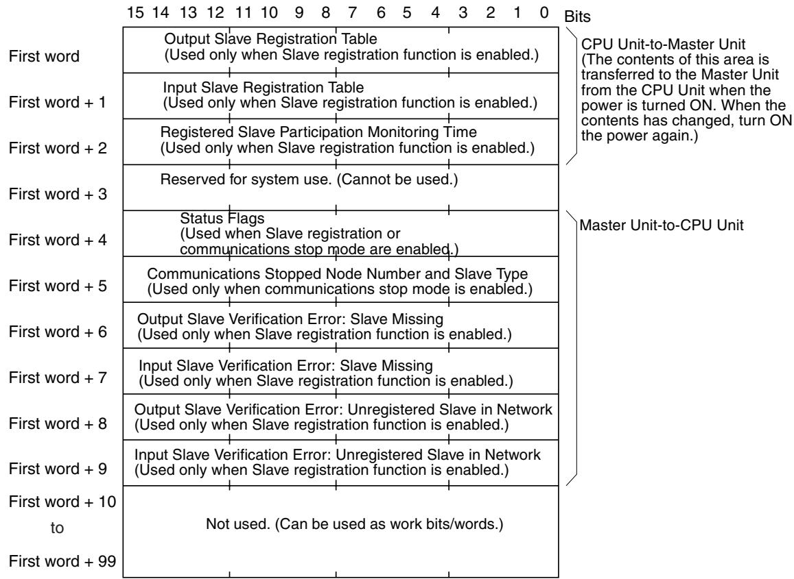
The contents from the first word to the first word +9 cannot be used for any other purpose. These words can be used, however, if the Slave registration function and communications stop mode are not enabled.
Checking Operations Using DM Area Words
The following table shows the functions of the words in the Master Unit's Special I/O Unit DM Area that are used to check operations.
For details on the words used to set the Slave registration function, refer to 4-3-5 Slave Registration Function and Communications Stop Mode.
| Word | Bit | Name | Function |
| +4 | 00 | Registration Completed Flag | This flag is turned ON when all registered Slaves have joined the network. If all the registered Slaves have joined the network within the registered Slave participation monitoring time this flag will turn ON even if unregistered Slaves have also joined. The flag will not turn ON, however, if there are no Slaves set in the Slave registration table. The flag will remain ON until the power is turned OFF and ON again or the Unit is restarted. |
| 08 | Verification Error Flag: Slave Missing | This flag is turned ON under the following conditions. Registered Slaves do not join the network within the registered Slave participation monitoring time. When the Slave that caused the verification error is joined in the network, the flag will automatically be turned OFF. Check which Slave caused the error in the bit for verification error (Slave missing) in Output Slave (first word + 6) or verification error (Slave missing) in Input Slave (first word + 7). | |
| 09 | Verification Error Flag: Unregistered Slave in Network | This flag is turned ON when an unregistered Slave has joined the network. The flag will remain ON until the power is turned OFF and ON again or the Unit is restarted, even if the Slave that caused the verification error is removed from the network. Check which Slave caused the error in the bit for Output Slave verification error (unregistered Slave in network) (first word + 8) or Input Slave verification error (unregistered Slave in network) (first word + 9). | |
| 10 | Communications Stopped Flag | This flag is turned ON when the Master Unit is set to communications stop mode and remote I/O communications stop due to a communications error.. Once the flag has turned ON, the status remains until the power is turned OFF and ON again or the Unit is restarted. Check which Slave caused the error in the bits for communications stopped node number (bits 00 to 07 of first word + 5) and communications stopped Slave type (bit 15 of first word + 5). | |
| 15 | Error Flag | This flag is turned ON when any of the bits 08 to 10 are set to1(ON). The flag is automatically turned OFF when all the bits 08 to 10 are turned OFF. | |
| +5 | 00 to 07 | Communications Stopped Node Number | When the Master Unit is set to communications stop mode and remote I/O communications stop due to a communications error, the node number of the Slave that caused the error is stored as a 2-digit hexadecimal (00 to 0F: 1 to 15). Check the Slave type (Output or Input) in the word for communications stopped Slave type (bit 15 of first word + 5). The node address stored will be held until the power is turned OFF and ON again or the Unit is restarted. |
| 15 | Communications Stopped Slave Type | When the Master Unit is set to communications stop mode and remote I/O communications stop due to a communications error, the Slave type of the Slave that caused the error is stored as follows: 0 (OFF): Output Slave 1 (ON): Input Slave Check which Slave caused the error in the bits for communications stopped node number (bits 00 to 07 of first word + 5) When communications have stopped, the bit status is held until the power is turned OFF and ON again or the Unit is restarted. |
| Word | Bit | Name | Function | ||
| +6 | 00 | Output Slave Verification Error: Slave Missing | OUT0 | When the Slave registration function is enabled, the bit corresponding to the node number of the Output Slave that caused the verification error (Slave missing) will be turned ON. | The bits in the Special I/O Unit Area correspond to the node numbers actually used by the Slaves. Therefore, for Slaves with 16 points or higher, the bits other than those set for the node number may also be turned ON. For example, the two consecutive bits used by a 16-point Slave or the four consecutive bits used by a 32-point Slave may be turned ON at the same time. |
| 01 | OUT1 | ||||
| 02 | OUT2 | ||||
| to | to | ||||
| 13 | OUT13 | ||||
| 14 | OUT14 | ||||
| 15 | OUT15 | ||||
| +7 | 00 | Input Slave Verification Error: Slave Missing | IN0 | When the Slave registration function is enabled, the bit corresponding to the node number of the Input Slave that caused the verification error (Slave missing) will be turned ON. | Bits 00 to 15 correspond to Input Slave node numbers 1 to 15. When the Slave that caused the verification error joins the network, the bit will automatically turned OFF. |
| 01 | IN1 | ||||
| 02 | IN2 | ||||
| to | to | ||||
| 13 | IN13 | ||||
| 14 | IN14 | ||||
| 15 | IN15 | ||||
| +8 | 00 | Output Slave Verification Error: Unregistered Slave in Network | OUT0 | When the Slave registration function is enabled, the bit corresponding to the node number of the Output Slave where a verification error (unregistered Slave in network) will be turned ON. | Bits 00 to 15 correspond to Output Slave node numbers 1 to 15. Once a bit has been turned ON the status will be held until the power is turned OFF and ON again or the Unit is restarted. |
| 01 | OUT1 | ||||
| 02 | OUT2 | ||||
| to | to | ||||
| 13 | OUT13 | ||||
| 14 | OUT14 | ||||
| 15 | OUT15 | ||||
| +9 | 00 | Input Slave Verification Error: Unregistered Slave in Network | IN0 | When the Slave registration function is enabled, the bit corresponding to the node number of the Input Slave where a verification error (unregistered Slave in network) will be turned ON. | Bits 00 to 15 correspond to Input Slave node numbers 1 to 15. Once a bit has been turned ON the status will be held until the power is turned OFF and ON again or the Unit is restarted. |
| 01 | IN1 | ||||
| 02 | IN2 | ||||
| to | to | ||||
| 13 | IN13 | ||||
| 14 | IN14 | ||||
| 15 | IN15 | ||||
6-3-4 Checking Normal Operations Using Ladder Programming
This section provides information on how to write a ladder program to monitor the operation of the CompoBus/S System and prohibit using the I/O data of the Slaves in the system when an error occurs or the Slaves are not participating in the network correctly.
Master Unit Settings
The following table shows the Master Unit settings used in the programming example (when all Slaves OUT0 to OUT15 and IN0 to IN15 are connected).
| Master's unit number | 0 |
| usable node numbers | IN0 to IN15 and OUT0 to OUT15 |
Example 1
Communications will be performed only when the Communications Error Flags of all Slaves are OFF, and the Active Node Flags correspond to the configuration of connected Slaves.
Status Area
(Refer to Status Flag Functions on page 97 and page 119 for details.)
| CIO 2016 | 15 | 14 | 13 | 12 | 11 | 10 | 9 | 8 | 7 | 6 | 5 | 4 | 3 | 2 | 1 | 0 | Bits |
| Output Slave Communications Error Flags | Active Output Slave Flags | ||||||||||||||||
| Slave 7 | Slave 7 | ||||||||||||||||
| CIO 2017 | Input Slave Communications Error Flags | Active Input Slave Flags | |||||||||||||||
| Slave 7 | Slave 7 | ||||||||||||||||
| CIO 2018 | Output Slave Communications Error Flags | Active Output Slave Flags | |||||||||||||||
| Slave 15 | Slave 15 | ||||||||||||||||
| CIO 2019 | Input Slave Communications Error Flags | Active Input Slave Flags | |||||||||||||||
| Slave 15 | Slave 15 | ||||||||||||||||
Active Node Flags:
Once a Slave joins the CompoBus/S network after the Slave is turned ON, the Active Node Flag corresponding to the Slave will be ON.
Communications Error Flags:
If a Slave in the network fails to communicate with the Master, the Communications Error Flag corresponding to the Slave will be ON. After the Communications Error Flag is ON, the previous input data from the input Slave will be kept on hold. While the Communications Error Flag is ON, the input data of the input Slave is not reliable. (The program will be executed with the previous data.)
Operations
The input conditions require the Input Slave and Output Slave Active Node Flags to match the network configuration and that the Output Slave or Input Slave Communications Error Flags are OFF.
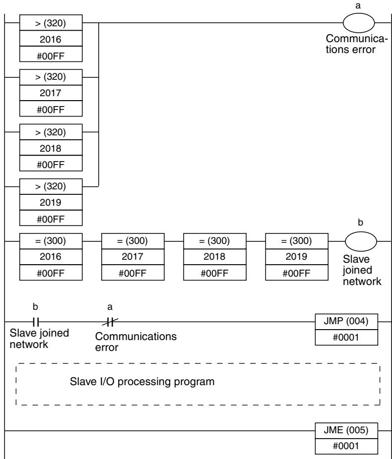
Determines that Communications Error Flags in leftmost 8 bits of DM 2016 to DM 2019 are OFF. If the Flag for any node is ON, the comparison result with constant #00FF is ON, and work bit turns ON.
Determines that Active Node Flags for Slaves in rightmost 8 bits of DM 2016 to DM 2019 match the Slave configuration.
Set the FF part of the constant #00FF to match the configuration of connected Slaves.
Slave I/O is processed when the JMP condition is ON only.
If the JMP condition is OFF, the program jumps to JME and Slave I/O is not processed.
Example 2
The input conditions can be set according to the following table when the Slave registration table and communications stop mode are used (DIP switch pins 3 and 4 both set to ON).
DM Area Contents
(Refer to Slave Registration Function and Communications Stop Mode on page 98 and page 120 for details.)
| DM address | Bit | Name | Function |
| D20004 | 00 | Registration Completed Flag | ON when all registered Slaves have joined network. |
| 08 | Verification Error Flag: Slave Missing | ON when a Slave are not present in network. | |
| 09 | Verification Error Flag: Unregistered Slave in Network | ON when an unregistered Slave is in the network. | |
| 10 | Communications Stopped Flag | ON when communications have stopped due to a communications error. | |
| 15 | Error Flag | ON when any of the flags 08 to 10 are ON. |
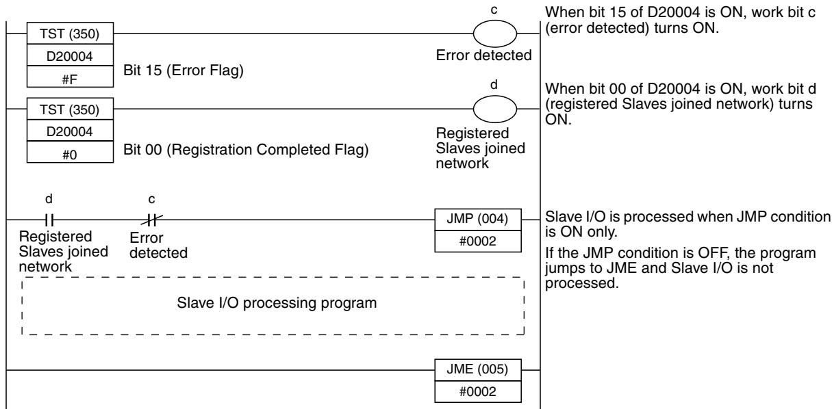
Operations
6-3-5 Troubleshooting
When an error occurs, the indicators of the Master Unit connected to a CS-series or CJ-series PLC will indicate the error. Check the Master Unit's indicators and perform the error processing described in the following table.
When an error occurs in a Slave, the Slave can be identified from the status of the Master's indicators (refer to page 76) or from the status flags (refer to page 365) in the PLC's Special I/O Unit Area.
| Error | Probable cause | Possible remedy |
| The Master Unit's RUN indicator is OFF | The PLC's power is OFF. | Turn the PLC's power supply ON. |
| The same unit number has been set on another Special I/O Unit, causing an area overlap error in the PLC. | Check that the same unit number is not used by more than one Special I/O Unit and restart the PLC. In particular, when the usable node number setting is IN0 to IN15 and OUT0 to OUT15, check that the next unit number after the one set on the Master Unit is not set on another Special I/O Unit. | |
| The unit number has been set outside the specified range, causing an area overlap error in the PLC. | Check that the unit number is set within the range specified for Special I/O Units and restart the PLC.CS-series and CJ-series PLCsUnit numbers 0 to 95 can be set when the Master Unit is using 10 words as a single Special I/O Unit and the usable node number setting is IN0 to IN7 and OUT0 to OUT7 (DIP switch pin 1 OFF).Unit numbers 0 to 94 can be set when the Master Unit is using 20 words as two Special I/O Units and the usable node number setting is IN0 to IN15 and OUT0 to OUT15 (DIP switch pin 1 ON). | |
| The usable node number setting was changed with the PLC power ON, and the Master Unit was restarted only. | Turn the PLC OFF and then ON again, and recreate the I/O tables. | |
| A Special I/O Unit error occurred in the PLC because the Master Unit is not connected securely. | Turn the PLC OFF, make sure that the Master Unit is mounted correctly, and then turn the PLC ON again. Replace the Master Unit if the error recurs. | |
| The Master Unit is faulty. | Replace the Master Unit. | |
| Communications stop mode is set. | Communications stop when a communications error occurs in communications stop mode. Remove the cause of the error, and then reset the Master Unit using the PLC's Restart Bit or turn the PLC OFF and then ON again. | |
| The Master Unit's SD indicator is OFF (when communications stop mode is not enabled) | --- | Either reset the Master Unit with the PLC's Restart Bit or turn the PLC OFF and then ON again. Replace the Master Unit if the error recurs. |
| The Master Unit's RD indicator is OFF | The communications cable is not connected to the Master. | Connect the communications cable correctly. |
| A Slave's number has been set to 8 to 15 even though the usable node address setting is IN0 to IN7 and OUT0 to OUT7. | Either change the Input and Output Slave's node number settings so that they are 0 to 7 or change the usable node number setting to IN0 to IN15 and OUT0 to OUT15. | |
| One of the Slaves is not turned ON. (The Slave's PWR indicator is OFF.) | Turn ON the Slave's power supply. | |
| There is a problem with the Slaves' power supply. | Check the power supply cable connections and connect the cables to the Slaves correctly. | |
| The Slaves' power supply is inadequate. | Check the power supply capacity. If it is inadequate, either change the system configuration or change the power supply so that sufficient power is provided. | |
| There is a problem with the communication cable connection or the cable itself. | Check the connections and cable. Replace the communications cable if it is faulty. | |
| Communications modes of Master Unit and Slave do not match. | Set the communications mode so that it is the same as that of the Master Unit. | |
| A common system mistake has been made. (Refer to the table on page 364 for a list of common mistakes.) | Refer to the table on page 364 for common mistakes and their remedies. | |
| The Master Unit is faulty. | Replace the Master Unit. | |
| The Master Unit's ERC indicator is ON | Power is not being supplied to the Slaves. | Turn ON the Slave's power supply. |
| There is a problem with the Slaves' power supply. | Check the power supply cable connections and connect the cables to the Slaves correctly. | |
| The Slaves' power supply is inadequate. | Check the power supply capacity. If it is inadequate, either change the system configuration or change the power supply so that sufficient power is provided. | |
| There is a problem with the communication cable connection or the电缆 itself. | Check the connections and cable. Replace the communications cable if it is faulty. | |
| There is a non-existent node number because a Slave's node number was changed after communications were established. | Either reset the Master Unit with the PLC's Restart Bit or turn the PLC OFF and then ON again. | |
| The same node number is used on two Slaves. | Change the Slaves' node number settings to eliminate the duplication and then turn the Slaves ON again. Either reset the Master Unit with the PLC's Restart Bit or turn the PLC OFF and then ON again. | |
| A registered Slave has not joined the network (when Slave registration function is enabled). | Check the Slave registration table and the node number setting for each Slave. | |
| An unregistered Slave is in the network (when Slave registration function is enabled). | ||
| A common system error has occurred. (Refer to the table on page 364 for a list of common errors.) | Refer to the table on page 364 for common errors and their remedies. | |
| The Master Unit is faulty. | Replace the Master Unit. | |
| A Slave Unit is faulty. | Replace the faulty Slave Unit. | |
| The Master Unit's ERH indicator is ON | The I/O table is not registered. | Recreate the I/O tables. |
| The same unit number has been set on another Special I/O Unit. | Check that the same unit number is not used by more than one Special I/O Unit and turn the PLC OFF and ON again. In particular, when the usable node number setting is IN0 to IN15 and OUT0 to OUT15, check that the next unit number after the one set on the Master Unit is not set on another Special I/O Unit. | |
| The unit number has been set outside the specified range. | Check that the unit number is set within the range specified for Special I/O Units and turn the PLC OFF and ON again. CS-series and CJ-series PLCsUnit numbers 0 to 95 can be set when the Master Unit is using 10 words as a single Special I/O Unit and the usable node number setting is IN0 to IN7 and OUT0 to OUT7 (DIP switch pin 1 OFF).Unit numbers 0 to 94 can be set when the Master Unit is using 20 words as two Special I/O Units and the usable node number setting is IN0 to IN15 and OUT0 to OUT15 (DIP switch pin 1 ON). | |
| The CPU Unit is faulty. | Replace the CPU Unit. | |
| A Slave Unit's COMM indicator is OFF or its ERR indicator is ON | An error has occurred at the Master Unit. | Check the Master Unit's indicators and follow the procedures listed above. |
| The Slave cannot participate in communications because its power supply is OFF. (The Slave's PWR indicator is OFF.) | Turn ON the Slave's power supply. | |
| The Slave cannot participate in communications because there is a problem with the Slaves' power supply. | Check the power supply cable connections and connect the cables to the Slaves correctly. | |
| The Slave cannot participate in communications because its power supply is inadequate. | Check the power supply capacity. If it is inadequate, either change the system configuration or change the power supply so that sufficient power is provided. | |
| The Slave cannot participate in communications because there is a problem with the communication cable connection or the cable itself. | Check the connections and cable. Replace the communications cable if it is faulty. | |
| The same node number is used on another Slave between inputs Slaves or between output Slaves. | Change one of the Slave's node number settings to eliminate the duplication and then turn the Slaves ON again. Either reset the Master Unit with the PLC's Restart Bit or turn the PLC OFF and then ON again. | |
| A Slave's number has been set to 8 to 15 even though the usable node number setting is IN0 to IN7 and OUT0 to OUT7. | Either change the Input and Output Slave's node number settings so that they are 0 to 7 or change the usable node number setting to IN0 to IN15 and OUT0 to OUT15. | |
| Communications modes of Master Unit and Slave do not match. | Set the communications mode so that it is the same as that of the Master Unit. | |
| A common system mistake has been made. (Refer to the table on page 376 for a list of common mistakes.) | Refer to the table on page 376 for common mistakes and their remedies. | |
| The Slave Unit is faulty. | Replace the Slave Unit. | |
| The area used by the Analog Terminal or 32-point Connector Terminal exceeds the range of the Master Unit I/O Area. | Change to node numbers that do not exceed the I/O Area range, then turn ON the PLC again. | |
| The indicators on the Master and Slaves are normal, but there are errors in the communications data | The same node number is set on two or more Input Slaves or Output Slaves. | Check the Active Node Flags for the Master and see whether the flags are ON for all of the connected Slaves. If there is a duplication, change the Slaves' node number settings. |
| The PLC's Output OFF Bit is ON, so the Output Slave outputs are always OFF. | Turn OFF the PLC's Output OFF Bit. | |
| The communications power supply to the Slaves is ON, but the I/O power supply is OFF, so the Output Slave outputs and Input Slave inputs are always OFF. | Provide an I/O power supply to the Slaves. | |
| There is a problem with the communication cable connection or the cable itself. | Check the connections and cable. Replace the communications cable if it is faulty. | |
| Usable node numbers setting is incorrect. | Refer to 4-2-3 I/O Allocations or 4-3-4 I/O Allocations and reset the usable node numbers to correct values. | |
| A common system mistake has been made. (Refer to the table on page 376 for a list of common mistakes.) | Refer to the table on page 376 for common mistakes and their remedies. | |
| The Master or a Slave Unit is faulty. | Replace the Slave Unit. Replace the Master Unit if the problem recurs. |
Common Mistakes
The following table shows common connection mistakes and their remedies.
| Mistake | Remedy |
| A terminator is not connected. | Connect a terminator (connector or terminal-block) at the end of the cable farthest from the Master. |
| The terminator is not connected at the end of the cable farthest from the Master. | Connect the terminator at the end of the cable farthest from the Master. |
| The master is not connected at one end of the main line in a system in which the main line must be distinguished from the branch lines. | Connect the Master at one end of the main line. |
| The length of the main line, a branch line, or the total length of the branch lines of the system in which the main line must be distinguished from the branch lines is not within specifications. | Make sure that the lengths of the cables in the system are within the specifications listed in 2-2-2 Maximum Cable Length, or change the communications mode to Long-distance Communications Mode so that the length of the cables in the system will be within specifications. |
| The total communications cable in the system in which the main line does not need to be distinguished from the branch lines is not within specifications. | Refer to 2-2-2 Maximum Cable Length and change the configuration so that the length of the total communications cable length will be within specifications. |
| 2-conductor VCTF cable, 4-conductor VCTF cable, and Special Flat Cable are used together in the same system. | Use just one kind of cable in the system. |
| There is a break in the communications cable. | Reconnect or replace the communications cable. |
| When 4-conductor VCTF cable or Special Flat Cable is being used, a connector is not attached securely to the cable. | Make sure that the connectors are crimped correctly on the cable. |
| A connector is faulty. | Replace the faulty connector. |
6-4 Checking Operations of CQM1 Master Units
6-4-1 Indicators
Error Status
The Master Unit's indicators can indicate operating errors.
| Situation | Indicator status | ALM Output | Probable cause | Possible remedy | ||||
| RUN | ERC | ERS | SD | RD | ||||
| Normal communications | ON | OFF | OFF | ON | ON | OFF | --- | --- |
| PLC's power OFF | OFF | OFF | OFF | OFF | OFF | OFF | The PLC's power is OFF. | Turn the PLC's power supply ON. |
| I/O UNIT OVER error | OFF | OFF | OFF | OFF | OFF | OFF | The PLC's limit on I/O points was exceeded by the CompoBus/S Master Unit. | Reduce the PLC word allocation setting or remove one of the other Units. |
| I/O BUS error | ON/OFF | OFF | OFF | OFF | OFF | OFF | The connection between the CPU Unit and I/O bus is not correct. | Check the mounting of each I/O Unit and the End Cover. Turn the PLC ON again after correcting the cause of the error. |
| Slave not connected | ON | OFF | OFF | ON | OFF | OFF | No Slaves are connected, or the communications mode of each Slave does not match that of the Master Unit. | Use a Slave that can communicate properly, or make the communications mode of each Slave match that of the Master Unit. |
| Data area over-lap | ON | --- | ON | OFF | OFF | ON | When the "number of points/node number" setting is set to 4, this status indicates that the same area is allocated to more than one Slave. Communications will be stopped. | Check the area allocated to the 8-point Slave where the error occurred, eliminate the area overlap, and then restart the PLC. See Communications Error Node Number Indicators below. |
| Address over error | ON | --- | Flashing | ON | ON | OFF | When the "PLC word allo-cation" setting is 2 or 4 words, this status indicates that an out-of-range node number from 0 to 7 has been set. | Check the indicators and set the node number to an acceptable value. See Communications Error Node Number Indicators below. |
| Communications error with a Slave | ON | ON | --- | ON | --- | ON | An error has occurred with a Slave during communications and it is withdrawn from the system. | Check the indicators and clear the cause of the communications error. See Communications Error Node Number Indicators below. |
Note Check the system's operation with just one Slave connected (one Slave at a time) if the CompoBus system doesn't operate but the Master's indicator status doesn't match any of those in the following table.
Communications Error Node Number Indicators
When a communications error occurs with a Slave during communications and the ERC indicator lights or the ERS indicator lights or flashes, the other indicators will show the node number of the Slave where the error occurred in binary.
When several communications errors occur simultaneously, the node number with the highest priority error will be displayed. The priority is as follows:
1,2,3...
- Area overlap error (ERS lit)
- Address over error (ERS flashing)
- Communications error (ERC lit)
When the same error occurs in two or more Slaves, the node number of the Slave with the first recognized error will be displayed. The display will not be changed if the same error occurs in another Slave while a node number is already being displayed for that error. The new node number can be displayed after the first error is cleared.
When a communications error occurs in a 16-point Slave, either one of the node numbers used by the Slave may be displayed.
The following table shows some examples of node number displays.
| Situation | Indicator status | Possible remedy | ||||||
| ERC | ERS | I/O | 8 | 4 | 2 | 1 | ||
| Area overlap in Output Slaves with node numbers 4 and 5 | --- | ON | ON | OFF | ON | OFF | OFF | Change the node number for Output Slave 4 or 5. Alternatively, change the "number of points/node number" setting to 8. Restart the PLC afterwards. |
| Address over error in the Input Slave with node number 7 | --- | Flashing | OFF | OFF | ON | ON | ON | Change the node number for Input Slave 7. Alternatively, change the "PLC word allocation" and "number of points/node number" settings. |
| Communications error in the Input Slave with node number 13 | ON | OFF | OFF | ON | ON | OFF | ON | Check the communications cable to Input Slave 13 and the status of the Slave itself. |
| Communications error in the Output Slave with node number 6 | ON | OFF | ON | OFF | ON | ON | OFF | Check the communications cable to Out-put Slave 6 and the status of the Slave itself. |
| Communications error in the Input Slave with node number 0 | ON | OFF | OFF | OFF | OFF | OFF | OFF | Check the communications cable to Input Slave 0 and the status of the Slave itself. |
| A communications error occurs in the Output Slave with node number 11 after a communications error occurs in the Input Slave with node number 3. | ON | OFF | OFF | OFF | OFF | ON | ON | First, check the communications cable to Input Slave 3 and the status of the Slave itself. Once the error in Input Slave 3 is cleared, the display will show the error in Output Slave 11 and this error can be cleared. |
6-4-2 Error Detection with the Alarm Output (CQM1 Only)
The CompoBus/S Master Unit for CQM1 PLCs is equipped with an alarm output terminal (ALM) which is shorted by an internal relay when an error occurs. The alarm output is shorted when there is an area overlap error (ERS indicator ON) or a communications error (ERC indicator ON).
The alarm output can be used to speed the response to an error by connecting the output to a warning device such as a buzzer or using the alarm output as an input to the PLC to trigger an error subroutine.
The following table shows the specifications for the alarm output terminal (ALM). Use these specifications for reference when wiring the alarm output.
| Item | Specification |
| Maximum switching capacity | 2 A (24 V DC) |
| Minimum switching capacity | 10 mA (5 V DC) |
| Relay model | G6D-1A |
| Minimum ON time | 100 ms (Outputs are ON at least 100 ms.) |
| Circuits configuration | CQM1-SRM21-V1 Internal circuit 24 V DC max. at 2 A |
6-4-3 Checking Normal Operations Using Ladder Programming
This section provides information on how to write a ladder program to monitor the operation of the CompoBus/S System and prohibit using the I/O data of the Slaves in the system when an error occurs or the Slaves are not participating in the network correctly.
The CQM1 Master Unit does not have a status area but an alarm output terminal (ALM) instead. The alarm output terminal is short-circuited if either of the following errors occur. (Refer to page 117.)
- Area duplication error (ERS indicator is lit)
- Communications error (ERC indicator is lit)
It is recommended to write a program that enables the Input Unit to accept alarm output and the I/O data of the Slaves in the network is used only when the alarm output terminal is OFF.
6-4-4 Troubleshooting
The indicators of a Master Unit connected to a CQM1 PLC will indicate when an error has occurred. Check the Master Unit's indicators and perform the error processing described in the following table.
When an error occurs in a Slave, the Slave can be identified from the status of the Master's indicators (refer to page 128) or from the status flags in the PLC's Special I/O Unit Area.
The alarm output can also be used to determine when an error has occurred. Refer to 6-4-2 Error Detection with the Alarm Output (CQM1 Only) for details.
| Error | Probable cause | Possible remedy |
| The Master Unit's RUN indicator is OFF | The PLC's power is OFF. | Turn the PLC's power supply ON. |
| An I/O UNIT OVER error occurred in the PLC. | Either change the PLC word allocation setting on pins 1 and 2 of the DIP switch or remove another I/O Unit. | |
| An I/O BUS error occurred in the PLC because the Master Unit is not connected securely. | Turn the PLC OFF, make sure that the Master Unit is mounted correctly, and then turn the PLC ON again. Replace the Master Unit if the error recurs. | |
| An I/O BUS error occurred in the PLC because the PLC's End Cover is not connected securely. | Turn the PLC OFF, make sure that the End Cover is mounted correctly, and then turn the PLC ON again. Replace the Master Unit if the error recurs. | |
| An I/O BUS error occurred in the PLC because the PLC word allocation setting (pins 1 and 2) was changed after communications were established. | Turn the PLC OFF and then ON again. | |
| The Master Unit is faulty. | Replace the Master Unit. | |
| The Master Unit's SD indicator is OFF | The same area may be allocated to more than one Slave. (The Master Unit's ERS indicator will be ON at the same time.) | See the explanation under “The Master Unit's ERS indicator is ON.” below. |
| The Master Unit is faulty. | Replace the Master Unit. | |
| The Master Unit's RD indicator is OFF | The communications cable is not connected to the Master. | Connect the communications cable correctly. |
| One of the Slaves is not turned ON.(The Slave's PWR indicator is OFF.) | Turn ON the Slave's power supply. | |
| There is a problem with the Slaves' power supply. | Check the power supply cable connections and connect the cables to the Slaves correctly. | |
| The Slaves' power supply is inadequate. | Check the power supply capacity. If it is inadequate, either change the system configuration or change the power supply so that sufficient power is provided. | |
| There is a problem with the communication cable connection or the cable itself. | Check the connections and cable. Replace the communications cable if it is faulty. | |
| Communications modes of Master Unit and Slave do not match. | Set the communications mode so that it is the same as that of the Master Unit. | |
| A common system mistake has been made.(Refer to the table on page 382 for a list of common mistakes.) | Refer to the table on page 382 for common mistakes and their remedies. | |
| The Master Unit or a Slave Unit is faulty. | Replace the Master Unit. Replace the Slave Units if the problem recurs. | |
| The Master Unit's ERS indicator is ON | The same area may be allocated to more than one Slave. | Either change the Slaves' node number settings to eliminate the I/O Area overlap or change the Master Unit's "number of points/node number" setting to 8-point mode by turning pin 3 of the DIP switch OFF. Turn the PLC ON again after making the necessary changes. |
| The PLC's data area has been exceeded. | Either change the node number setting of the Slave that exceeded the PLC's I/O Area or change the Master Unit's "number of points/node number" setting to 8-point mode by turning pin 3 of the DIP switch OFF. Turn the PLC ON again after making the necessary changes. | |
| A 16-point or greater Slave has been con- nected even though the Master Unit's num- ber of points/node number setting is 4-point mode.(Pin 3 of the DIP switch is ON.) | Either remove the 16-point or greater Slave or change the Master Unit's number of points/node number setting to 8-point mode by turning pin 3 of the DIP switch OFF. Turn the PLC ON again after making the necessary changes. | |
| There is a problem with the communication cable connection or the cable itself. | Check the connections and cable. Replace the communications cable if it is faulty. | |
| A Slave Unit is faulty. | Replace the faulty Slave Unit. | |
| The Master Unit's ERS indicator is flashing | The "PLC word allocation" setting is 2 or 4 words, but an out-of-range node number from 0 to 7 has been set.(An address over error occurred.) | Either remove the Slave where the error occurred or change the Master's PLC word allocation set- ting (pins 1 and 2) and max. number of Slaves set- ting (pin 3) so that the Slave's node number is acceptable.Refer to 4-4-2 Switch Settings for a table showing all of the possible DIP switch settings. |
| A Slave Unit is faulty. | Replace the faulty Slave Unit. | |
| The Master Unit's ERC indicator is ON | Power is not being supplied to the Slaves. | Turn ON the Slave's power supply. |
| There is a problem with the Slaves' power supply. | Check the power supply cable connections and connect the cables to the Slaves correctly. | |
| The Slaves' power supply is inadequate. | Check the power supply capacity. If it is inadequate, either change the system configuration or change the power supply so that sufficient power is provided. | |
| There is a problem with the communication cable connection or the cable itself. | Check the connections and cable. Replace the communications cable if it is faulty. | |
| There is a non-existent node number because a Slave's node number was changed after communications were established. | Either reset the Master Unit with the PLC's Restart Bit or turn the PLC OFF and then ON again. | |
| The same node number is set on two or more Input Slaves or Output Slaves. | After changing the Slaves' node number settings to eliminate the duplication, turn the Slaves ON again and then turn the PLC ON again. | |
| A common system mistake has been made. (Refer to the table on page 382 for a list of common mistakes.) | Refer to the table on page 382 for common mistakes and their remedies. | |
| A Slave Unit is faulty. | Replace the faulty Slave Unit. | |
| A Slave Unit's COMM indicator is OFF or its ERR indicator is ON | An error has occurred at the Master Unit. | Check the Master Unit's indicators and follow the procedures listed above. |
| The Slave cannot participate in communications because its power supply is OFF. (The Slave's PWR indicator is OFF.) | Turn ON the Slave's power supply. | |
| The Slave cannot participate in communications because there is a problem with the Slaves' power supply. | Check the power supply cable connections and connect the cables to the Slaves correctly. | |
| The Slave cannot participate in communications because its power supply is inadequate. | Check the power supply capacity. If it is inadequate, either change the system configuration or change the power supply so that sufficient power is provided. | |
| The Slave cannot participate in communications because there is a problem with the communication cable connection or the cable itself. | Check the connections and cable. Replace the communications cable if it is faulty. | |
| The node address set for the Slave is outside the setting range. When outside the setting range with the node addresses 0 to 7: ERS indicator of the Master Unit flashes When outside the setting range with the node address 8 to 15: ERS indicator of the Master Unit goes OFF | Change the node address of the Slave that caused the address over or change the Master Unit's PLC word allocation setting (pins 1 and 2) and max. number of Slaves setting (pin 3) so that the Slave's node number is acceptable. Refer to 4-4-2 Switch Settings for a table showing all of the possible DIP switch settings. | |
| The same node number is set on two or more Input Slaves or Output Slaves. | Change one of the Slave's node number settings to eliminate the duplication, turn the Slave ON again, and then turn the PLC ON again. | |
| Communications modes of Master Unit and Slave do not match. | Set the communications mode so that it is the same as that of the Master Unit. | |
| A common system mistake has been made. (Refer to the table on page 382 for a list of common mistakes.) | Refer to the table on page 382 for common mistakes and their remedies. | |
| The Slave Unit is faulty. | Replace the Slave Unit. | |
| The indicators on the Master and Slaves are normal, but there are errors in the communications data | The same node number is set on two or more Input Slaves or Output Slaves. | Change one of the Slave's node number settings to eliminate the duplication, turn the Slave ON again, and then turn the PLC ON again. |
| The PLC's Output OFF Bit is ON, so the Output Slave outputs are always OFF. | Turn OFF the PLC's Output OFF Bit. | |
| The communications power supply to the Slaves is ON, but the I/O power supply is OFF, so the Output Slave outputs and Input Slave inputs are always OFF. | Provide an I/O power supply to the Slaves. | |
| There is a problem with the communication cable connection or the cable itself. | Check the connections and cable. Replace the communications cable if it is faulty. | |
| The setting of the number of words allocated to the PLC, or the number of points allocated to a single node number is incorrect. | Refer to 4-4-3 I/O Allocations in CQM1 PLCs and correct the number of words allocated to the PLC or the number of points allocated to a single node number. | |
| An Analog Terminal is connected to a CQM1-SRM21 (without V1). | Change the Master Unit to a CQM1-SRM21-V1. | |
| A common system mistake has occurred. (Refer to the table on page 382 for a list of common mistakes.) | Refer to the table on page 382 for common mistakes and their remedies. | |
| The Master or a Slave Unit is faulty. | Replace the Slave Unit. Replace the Master Unit if the problem recurs. |
Common Mistakes
The following table shows common connection mistakes and their remedies.
| Mistake | Remedy |
| A terminator is not connected. | Connect a terminator (connector or terminal-block) at the end of the cable farthest from the Master. |
| The terminator is not connected at the end of the cable farthest from the Master. | Connect the terminator at the end of the cable farthest from the Master. |
| The master is not connected at one end of the main line of the system that has the main line distinguishable from the branch lines. | Connect the Master at one end of the main line. |
| The length of the main line, a branch line, or the total length of the branch lines of the system in which the main line must be distinguished from the branch lines is not within specifications. | Make sure that the lengths of the cables in the system are within the specifications listed in 2-2-2 Maximum Cable Length, or change the communications mode to Long-distance Communications Mode so that the length of the cables in the system will be within specifications. |
| The total communications cable in the system in which the main line does not need to be distinguished from the branch lines is not within specifications. | Refer to 2-2-2 Maximum Cable Length and change the configuration so that the length of the total communications cable length will be within specifications. |
| 2-conductor VCTF cable, 4-conductor VCTF cable, and Special Flat Cable are used together in the same system. | Use just one kind of cable in the system. |
| There is a break in the communications cable. | Reconnect or replace the communications cable. |
| When 4-conductor VCTF cable or Special Flat Cable is being used, a connector is not attached securely to the cable. | Make sure that the connectors are crimped correctly on the cable. |
| A connector is faulty. | Replace the faulty connector. |
6-5 Checking Slave Operations
6-5-1 Indicators
This section explains the indicators common to all of the Slave Units. In addition to these common indicators, Slaves have other indicators, such as indicators that reflect the status of the Slave's I/O point. Refer to SECTION 5 Slave Specifications and Operations for details on the indicators specific to each Slave.
Indicator Meanings
The following table shows the meaning of the common indicators.
| Indicator | Color | Status | Meaning |
| PWR (POWER OUT) | Green | ON | The communications power supply is ON. |
| OFF | The communications power supply is OFF. | ||
| COMM | Yellow | ON | Normal communications |
| OFF | A communications error has occurred or the Unit is in standby status. | ||
| ERR (BUS/S ERR) | Red | ON | A communications error has occurred. |
| OFF | Normal communications or the Unit is in standby status. |
Indicator Status for Errors
The following table shows the status of the common indicators when an error occurs. Check the Master's indicators to determine the node number of the Slave in which the error occurred. The Slave's node number will also be indicated in the status area (not provided in CQM1 Master Units) allocated in the Special I/O Unit Area of the Master Unit.
| Situation | Indicator status | Probable cause | Possible remedy | ||
| PWR | COMM | ERR | |||
| Slave's power OFF | OFF | OFF | OFF | The Slave's power is OFF. | Turn the Slave's power supply ON. |
| Data area overlap | ON | OFF | ON | With a CQM1 Master that's "number of points/node number" setting is set to 4, the same area may be allocated to more than one Slave. Communications will be stopped. | Check the area allocated to the 8-point Slave where the error occurred, eliminate the area overlap, and then restart the PLC. |
| Address over error | ON | ON | OFF | With a CQM1 Master that's "PLC word allocation" setting is 2 or 4 words, an out-of-range node number from 0 to 7 may have been set. | Check the Master's indicators to determine the node number and set the node number within the speci-fied range. |
| Node number out-of-range error | ON | OFF | OFF | With a CQM1 Master, an out-of-range node number from 8 to 15 may have been set.When a CS-series, C200HX/C200HG/C200HE-(Z)E, and C200HS Master Unit, CS-series Master Unit, or CJ-series Master Unit is used and the range of usable node numbers is from 0 to 7, there are Slaves whose node numbers are set between 8 and 15. | Check the Master's indicators to determine the node number and set the node number within the speci-fied range. |
| Communications mode conflict | ON | OFF | OFF | The communications mode setting of the Master Unit does not match that of the Slave. | Make the communications mode of the Master Unit and Slave agree, then power-up the Master Unit again. |
| Communications error | ON | OFF | ON | An error has occurred with a Slave during communications and it is withdrawn from the system. | Check the Master's indicators and clear the cause of the communica-tions error. |
| Master's power OFF | ON | OFF | --- | The Master's power is OFF. | Turn ON the Master's power supply. |
Errors Limited to Analog Terminals
| Situation | Indicator status | Probable cause | Possible remedy | |||
| RUN | COMM | ERR | U. ERR | |||
| Analog Terminal Error | ON | OFF | OFF | ON | An error has occurred in inter- nal circuits of the CPU, ana- log-digital converter or digital- analog converter, etc. | Power-up the Slave again. If the Slave does not return to normal, replace it. |
6-6 Cleaning and Inspection
This section describes the routine cleaning and inspection recommended as regular maintenance.
6-6-1 Cleaning
Clean the CompoBus/S regularly as described below in order to keep it in its optimal operating condition.
- Wipe the Unit with a dry, soft cloth for regular cleaning.
- When a spot cannot be removed with a dry cloth, dampen the cloth with a neutral cleanser, wring out the cloth, and wipe the Unit.
- A smudge may remain on the Unit from gum, vinyl, or tape that was left on for a long time. Remove the smudge when cleaning.
Caution
Never use volatile solvents such as paint thinner or benzene or chemical wipes. These substances could damage the surface of the Unit.
6-6-2 Inspection
Be sure to inspect the system periodically to keep it in optimal operating condition. In general, inspect the system once every 6 to 12 months, but inspect more frequently if the system is used with high temperature or humidity or under dirty/dusty conditions.
Inspection Equipment
Prepare the following equipment before inspecting the system.
Required Equipment
Have a standard and phillips screwdriver, multimeter, alcohol, and a clean cloth.
Equipment that Could be Needed
Depending on the system conditions, you might need a synchroscope, oscilloscope, thermometer, or hygrometer (to measure humidity).
Inspection Procedure
Check the items in the following table and correct any items that are below standard.
| Item | Standard | Equipment | |
| Environmental conditions | Ambient and cabinet temperature | See below. | Thermometer |
| Ambient and cabinet humidity | See below. | Hygrometer | |
| Dust/dirt accumulation | None | Visual inspection | |
| Installation | Are the Units mounted securely? | No looseness | Phillips screw-driver |
| Are the connecting cable connectors fully inserted? | No looseness | Phillips screw-driver | |
| Are the external wiring screws tight? | No looseness | Phillips screw-driver | |
| Are the connecting cables undamaged? | No damage | Visual inspection | |
The following table shows the acceptable operating temperature and operating humidity ranges for CompoBus/S Units.
| Unit | Acceptable temperature | Acceptable humidity* |
| Master Unit | 0 to 55°C | 10% to 90% |
| Remote Terminal | 0 to 55°C | 35% to 85% |
| Remote I/O Module | 0 to 55°C | 35% to 85% |
| Sensor Amplifier Terminal | 0 to 55°C | 35% to 85% |
| Sensor Terminal | 0 to 55°C | 35% to 85% |
| Fiber Amplifier Communications Unit | -20 to 55°C | 35% to 85% |
| Connector Terminal | -10 to 55°C | 25% to 85% |
| Water-resistant Terminal | -10 to 55°C | 25% to 85% |
| Analog Terminal | -10 to 55°C | 25% to 85% |
| CPM1A/CPM2A I/O Link Unit | 0 to 55°C | 10% to 90% |
| CPM2C I/O Link Unit | 0 to 55°C | 10% to 90% |
Note Acceptable humidity range with no condensation or frost.
6-7 Precautions for Replacement of Units or Parts
The CompoBus/S Master Unit and Slave Units make up the system. The entire system is affected when a Unit is faulty, so a faulty Unit must be repaired or replaced quickly. We recommend having spare Units available to restore operation as quickly as possible.
6-7-1 Precautions for Unit Replacement
Observe the following precautions when replacing a faulty Unit.
- After replacement make sure that there are no errors with the new Unit.
- When a Unit is being returned for repair, attach a sheet of paper detailing the problem and return the Unit to your OMRON dealer.
- If there is a faulty contact, try wiping the contact with a clean, lint-free cloth dampened with alcohol. Re-mount the Unit after cleaning off any lint.
Caution
To prevent electric shock when replacing a Unit, be sure to turn OFF the power supplies to all of the nodes (Master and Slaves) before removing the faulty Unit.
6-7-2 Settings after Unit Replacement
After replacing a Unit, set the new Unit's switches to the same settings that were on the old Unit.
Caution
When the CPU Unit has been replaced, transfer any required DM Area or HR Area data to the new CPU Unit before restarting operation.
6-7-3 Replacing Relays
Faulty relays or power MOSFET relays in Remote Terminals can be removed and replaced.
Caution
Be sure to turn OFF the Slave's power supply before removing the faulty relay to prevent electric shock.
The relay's pins often bend or break when the relay is removed, so remove faulty relays only.
Remote Terminal Relays
Use the following procedure to replace a relay in an Remote Terminal.
1,2,3...
-
The relay removal tool attached to the Remote Terminal is used to remove the relay. Align the relay removal tool so that it squeezes the old relay, push it all the way in, and pull it out to remove the relay.
-
Check the orientation of the new relay carefully and insert it to the same depth as the other relays.
Appendix
Standard Models
Masters
Master Units
| Model | Applicable PLCs |
| C200HW-SRM21-V1 | CS-series, C200HX/C200HG/C200HE-(Z)E, and C200HS |
| CS1W-SRM21 | CS-series |
| CJ1W-SRM21 | CJ-series |
| CQM1-SRM21-V1 | CQM1 |
SRM1 Master Control Units
| Model | Specifications |
| SRM1-C01-V2 | Dedicated CompoBus/S controller without RS-232C connector |
| SRM1-C02-V2 | Dedicated CompoBus/S controller with RS-232C connector |
CPM2C-S Programmable Controllers
| Model | Specifications |
| CPM2C-S100C | CPU Unit with CompoBus/S Master functions, 6 transistor inputs, 4 transistor outputs (NPN) |
| CPM2C-S110C | CPU Unit with CompoBus/S Master functions, 6 transistor inputs, 4 transistor outputs (PNP) |
| CPM2C-S100C-DRT | CPU Unit with CompoBus/S Master functions, DeviceNet Slave functions, 6 transistor inputs, 4 transistor outputs (NPN) |
| CPM2C-S110C-DRT | CPU Unit with CompoBus/S Master functions, DeviceNet Slave functions, 6 transistor inputs, 4 transistor outputs (PNP) |
Other Masters
| Model | Specifications |
| 3G8B3-SRM□1 | CompoBus/S VME Board |
| C200PC-ISA□2-SRM | SYSMAC Board |
| SDD-CS1 | Uniline CompoBus/S Send Unit, manufactured by NKE |
Slaves
Remote Terminals
| Model | Specifications | |
| Compatible with High-speed Communications Mode | Compatible with High-speed and Long-distance Communications Modes | |
| SRT1-ID04 | SRT2-ID04 | 4 transistor inputs, two independent power supplies (NPN) |
| SRT1-ID04-1 | SRT2-ID04-1 | 4 transistor inputs, two independent power supplies (PNP) |
| SRT1-ID08 | SRT2-ID08 | 8 transistor inputs, two independent power supplies (NPN) |
| SRT1-ID08-1 | SRT2-ID08-1 | 8 transistor inputs, two independent power supplies (PNP) |
| SRT1-ID16 | SRT2-ID16 | 16 transistor inputs, two independent power supplies (NPN) |
| SRT1-ID16-1 | SRT2-ID16-1 | 16 transistor inputs, two independent power supplies (PNP) |
| SRT1-ID16T | SRT2-ID16T | 3-tier terminal block, 16 transistor inputs, two independent power supplies (NPN) |
| SRT1-ID16T-1 | SRT2-ID16T-1 | 3-tier terminal block, 16 transistor inputs, two independent power supplies (NPN) |
| SRT1-OD04 | SRT2-OD04 | 4 transistor outputs, two independent power supplies (NPN) |
| SRT1-OD04-1 | SRT2-OD04-1 | 4 transistor outputs, two independent power supplies (PNP) |
| SRT1-OD08 | SRT2-OD08 | 8 transistor outputs, two independent power supplies (NPN) |
| SRT1-OD08-1 | SRT2-OD08-1 | 8 transistor outputs, two independent power supplies (PNP) |
| SRT1-OD16 | SRT2-OD16 | 16 transistor outputs, two independent power supplies (NPN) |
| SRT1-OD16-1 | SRT2-OD16-1 | 16 transistor outputs, two independent power supplies (PNP) |
| SRT1-OD16T | SRT2-OD16T | 3-tier terminal block, 16 transistor outputs, two independent power supplies (NPN) |
| SRT1-OD16T-1 | SRT2-OD16T-1 | 3-tier terminal block, 16 transistor outputs, two independent power supplies (NPN) |
| SRT1-MD16T | SRT2-MD16T | 3-tier terminal block, 8 transistor inputs, 8 transistor outputs, two independent power supplies (NPN) |
| SRT1-MD16T-1 | SRT2-MD16T-1 | 3-tier terminal block, 8 transistor inputs, 8 transistor outputs, two independent power supplies (NPN) |
| SRT1-ROC08 | SRT2-ROC08 | 8 relay outputs, local power supply |
| SRT1-ROC16 | SRT2-ROC16 | 16 relay outputs, local power supply |
| SRT1-ROF08 | SRT2-ROF08 | 8 power MOS FET outputs, local power supply |
| SRT1-ROF16 | SRT2-ROF16 | 16 power MOS FET outputs, local power supply |
Connector Terminals
| Model | Specifications |
| SRT2-VID08S | Connection with sensor connector (for cable connection), 8 transistor inputs, multiple power supplies (NPN) |
| SRT2-VID08S-1 | Connection with sensor connector (for cable connection), 8 transistor inputs, multiple power supplies (PNP) |
| SRT2-VID16ML | Connection with MIL connector, 16 transistor inputs, multiple power supplies (NPN) |
| SRT2-VID16ML-1 | Connection with MIL connector, 16 transistor inputs, multiple power supplies (PNP) |
| SRT2-ID32ML | Connection with MIL connector, 32 transistor inputs, multiple power supplies (NPN) |
| SRT2-ID32ML-1 | Connection with MIL connector, 32 transistor inputs, multiple power supplies (PNP) |
| SRT2-MD32ML | Connection with MIL connector, 16 transistor inputs, 16 transistor outputs, multiple power supplies (NPN) |
| SRT2-MD32ML-1 | Connection with MIL connector, 16 transistor inputs, 16 transistor outputs, multiple power supplies (PNP) |
| SRT2-VOD08S | Connection with sensor connector (for cable connection), 8 transistor outputs, multiple power supplies (NPN) |
| SRT2-VOD08S-1 | Connection with sensor connector (for cable connection), 8 transistor outputs, multiple power supplies (PNP) |
| SRT2-VOD16ML | Connection with MIL connector, 16 transistor outputs, multiple power supplies (NPN) |
| SRT2-VOD16ML-1 | Connection with MIL connector, 16 transistor outputs, multiple power supplies (PNP) |
| SRT2-OD32ML | Connection with MIL connector, 32 transistor outputs, multiple power supplies (NPN) |
| SRT2-OD32ML-1 | Connection with MIL connector, 32 transistor outputs, multiple power supplies (PNP) |
All models are compatible with both High-speed and Long-distance Communications Modes.
Remote I/O Modules
| Model | Specifications | |
| Compatible with High-speed Communications Mode | Compatible with High-speed and Long-distance Communications Mode | |
| SRT1-ID16P | SRT2-ID16P | Mounted to PCB, 16 inputs (NPN) |
| SRT1-OD16P | SRT2-OD16P | Mounted to PCB, 16 outputs (NPN) |
Not compatible with Long-distance Communications Mode.
Sensor Amplifier Terminals
| Model | Specifications |
| Compatible with High-speed Communications Mode | |
| SRT1-TID04S | 4 inputs (1 channel × 4 units), Communications Terminal, network power supply |
| SRT1-TKD04S | 4 inputs (4 channels × 1 unit), Communications Terminal, network power supply |
| SRT1-XID04S | 4 inputs (1 channel × 4 units), Expansion Terminal |
| SRT1-XKD04S | 4 inputs (4 channels × 1 unit), Expansion Terminal |
Not compatible with Long-distance Communications Mode.
Fiber Amplifier Communications Unit
| Model | Specifications |
| E3X-SRT21 | 8 inputs or 16 inputs (includes 2 status points) from Fiber Amplifier Unit, network power supply |
This model is compatible with both High-speed and Long-distance Communications Modes.
Analog Terminals
| Model | Specifications |
| SRT2-AD04 | 4 analog inputs (switchable between 4, 3, 2, and 1 points), network power supply |
| SRT2-DA02 | 2 analog outputs (switchable between 2 and 1 points), network power supply |
Both models are compatible with both High-speed and Long-distance Communications Modes.
Sensor Terminals
| Model | Specifications | |
| Compatible with High-speed Communications Mode | Compatible with High-speed and Long-distance Communications Modes | |
| SRT1-ID08S | SRT2-ID08S | 8 inputs, network power supply |
| SRT1-ND08S | SRT2-ND08S | 4 inputs/4 outputs, network power supply |
| SRT1-OD08S | SRT2-OD08S | 8 outputs, local power supply |
Water-resistant Terminals
| Model | Specifications |
| SRT2-ID04CL | Connection with shielded connector (round water-resistant connector), 4 transistor inputs (NPN), multiple power supplies, IP67 enclosure ratings |
| SRT2-ID04CL-1 | Connection with shielded connector (round water-resistant connector), 4 transistor inputs (PNP), multiple power supplies, IP67 enclosure ratings |
| SRT2-ID08CL | Connection with shielded connector (round water-resistant connector), 8 transistor inputs (NPN), multiple power supplies, IP67 enclosure ratings |
| SRT2-ID08CL-1 | Connection with shielded connector (round water-resistant connector), 8 transistor inputs (PNP), multiple power supplies, IP67 enclosure ratings |
| SRT2-OD04CL | Connection with shielded connector (round water-resistant connector), 4 transistor outputs (NPN), multiple power supplies, IP67 enclosure ratings |
| SRT2-OD04CL-1 | Connection with shielded connector (round water-resistant connector), 4 transistor outputs (PNP), multiple power supplies, IP67 enclosure ratings |
| SRT2-OD08CL | Connection with shielded connector (round water-resistant connector), 8 transistor outputs (NPN), multiple power supplies, IP67 enclosure ratings |
| SRT2-OD08CL-1 | Connection with shielded connector (round water-resistant connector), 8 transistor outputs (PNP), multiple power supplies, IP67 enclosure ratings |
All models are compatible with both High-speed and Long-distance Communications Modes.
Bit Chain Terminal (Manufacturing Discontinued)
| Model | Specifications |
| SRT1-B1T | 8 inputs, 8 outputs (switchable between inputs and outputs in a batch), local power supply |
Not compatible with Long-distance Communications Mode.
I/O Link Unit for CPM1A/CPM2A
| Model | Specifications |
| CPM1A-SRT21 | 8 inputs, 8 outputs, data exchange with CPM1A/CPM2A CPU Units |
This model is compatible with both High-speed and Long-distance Communications Modes.
I/O Link Unit for CPM2C
| Model | Specifications |
| CPM2C-SRT21 | 8 inputs, 8 outputs, data exchange with CPM2C CPU Unit |
This model is compatible with both High-speed and Long-distance Communications Modes.
Other Slaves
| Model | Specifications |
| FND-X06H-SRT | Position Driver, 200-VAC input, 6 A |
| FND-X12H-SRT | Position Driver, 200-VAC input, 12 A |
| FND-X25H-SRT | Position Driver, 200-VAC input, 25 A |
| FND-X50H-SRT | Position Driver, 200-VAC input, 50 A |
| FND-X06L-SRT | Position Driver, 100-VAC input, 6 A |
| FND-X12L-SRT | Position Driver, 100-VAC input, 12 A |
Not compatible with Long-distance Communications Mode.
- Slaves Manufactured by Other Companies
| Model/Series | Specifications |
| VQ Series | SI manifold solenoid valve manufactured by SMC Corporation |
| SX Series | |
| SY Series | |
| MN4TB1 and MN4TB2 Series | Solenoid valve with reduced wiring manufactured by CKD Corporation |
| M4TB3 and M4TB4 Series | |
| M4G Series | |
| MN4S0 Series | |
| YS1A1, A2 | Valve with reduced wiring manufactured by KOGANEI Corporation |
| YS2A1, A2 |
Contact the manufacturer for details.
Standard Connection Devices
Communications Cables
| Manufacturer | Model | Remarks |
| Commercially available | VCTF cable (JIS C3306), 2 conductors (0.75 mm² each) | |
| VCTF cable (JIS C3306), 4 conductors (0.75 mm² each) | ||
| OMRON | SCA1-4F10 | OMRON Flat Cable, 100 m, 4 conductors (0.75 mm² each) |
| Belden (U.S.A.) | #9409 | Designated communications cable. (See note 1.) |
| Belden (U.S.A.) | #8489 | Designated communications cable. (See note 2.) |
Note 1. Electrical characteristics of the #9409 Belden communications cable are the same as those for the commercially available 2-conductor VCTF cable.
2. Electrical characteristics of the #8489 Belden communications cable are the same as those for the commercially available 4-conductor VCTF cable.
Connectors
| Model | Specifications | |
| Branch Connector | SCN1-TH4 | Use this connector to branch a cable. (Used with OMRON Flat Cable only.) |
| Extension Connector | SCN1-TH4E | Use this connector to extend the OMRON Flat Cable. |
| Connector Terminator | SCN1-TH4T | This connector has a built-in terminator. (Used with OMRON Flat Cable only.) |
| Round Water-resistant Connectors with Cable (socket and plug) | XS2W-D42□-□81-□ | Use this connector to connect Water-resistant Terminals and T-joints. Can be used as a power supply cable (with the female socket connected to the Water-resistant Terminal). Can be used as an I/O cable for sensors that have connectors (with the male plug connected to the Water-resistant Terminal, if the product has a model number suffix “A”). |
| Connector with Cable (female socket on one end) | XS2F-D42□-□80-□ | A connector with cable used to connect Water-resistant Terminals to T-branch connectors. Can be used as a power supply cable (with the female socket connected to the Water-resistant Terminal) and the other end wired to a commercially available terminal block. |
| Connector with Cable (male plug on one end) | XS2H-D421-□80-A | A connector with cable used to connect Water-resistant Terminals to I/O devices. Can be used as an I/O cable (with the male plug connected to the Water-resistant Terminal) and the other end wired to the I/O device with loose wires. |
| Connector Socket Assembly (female) (Crimp terminals/Solder terminals) | XS2C-D4S7 | A connector used to connect to the communications connectors or external power supply connectors of Water-resistant Terminals or T-joint plugs. Applicable cable dia.: 3 to 6 mm Applicable conductor size: 0.18 to 0.75 mm² |
| XS2C-D4□□ | A connector used to connect to the external power supply connectors of Water-resistant Terminals or T-joint plugs. Applicable cable dia.: 3 to 6 mm Applicable conductor size: 0.18 to 0.3 or 0.5 to 0.75 mm² | |
| Connector Plug Assembly (male) (Crimp terminals/Solder terminals) | XS2G-D4S7 | A connector used to connect to T-joint sockets. Applicable cable dia.: 6 to 8 mm Applicable conductor size: 0.18 to 0.75 mm² |
| XS2G-D4□□ | A connector used to connect to I/O connectors of Water-resistant Terminals or T-joint sockets. Applicable cable dia.: 3 to 6 mm Applicable conductor size: 0.18 to 0.3 or 0.5 to 0.75 mm² | |
| T-joint | XS2R-D427-5 | A joint used to T-branch a VCTF cable (e.g., a communications cable or power supply cable). |
| Communications Connector (6-pin) | FK-MCP1.5/6-STF-3.81 | A communications connector for connecting CJ-series Master Units. Communications cables (BD H, BD L, BS+, BS-) and communications power lines (BS+, BS-) can be connected simultaneously. This connector has screwless terminals for signal lines and connector lock screws. |
| MC1.5/6-STF-3.81 | A communications connector for connecting CJ-series Master Units. Communications cables (BD H, BD L, BS+, BS-) and communications power lines (BS+, BS-) can be connected simultaneously. This connector has screw terminals for signal lines and connector lock screws. | |
| Communications Connector (Connector Terminals) | BL3.5/6F (Product No. 160668) | Communications cables, communications power supply and I/O power supply connectors manufactured by Weidmuller Co., Ltd. |
| Shielded Terminator Plug (Male) | SRS2-1 | A shielded terminator plug used to connect to T-joints. |
| Terminal-block Terminator | SRS1-T | This terminal block has a built-in terminator. (Can be used with 2- or 4-conductor VCTF cable and OMRON's Special Flat Cable.) |
Other Products
Connector Terminal Mounting Brackets
SRT2-ATT01 Mounting Bracket A
SRT2-ATT02 Mounting Bracket B
Related Slaves: Connector Terminals
Cable Connectors
Related Slaves: Connector Terminals with Sensor Connectors, Remote Terminals with Connector Output Transistors, Sensor Terminals
| Model | Marking | Applicable wire size |
| XS8A-0441 | XS8-1 | 0.3 to 0.5 mm² |
| XS8A-0442 | XS8-2 | 0.14 to 0.2 mm² |
MIL Connectors
Related Slaves: Connector Terminals with MIL Connectors
| Model | Remarks |
| XG4M-2030-T | MIL Connector for SRT2-V□D16ML (-1) |
| XG4M-4030-T | MIL Connector for SRT2-□D32ML (-1) |
MIL Connector Cables for SRT2-V□D16ML(-1)
| Slave model number | Connecting cable | Compatible product |
| SRT2-VID16ML | G79-150C (50 cm) | G7TC-IA16/ID16 |
| G79-125C (25 cm) | ||
| G79-050C (50 cm) | XW2D-20G6 | |
| G79-025C (25 cm) | XW2B-20G5/20G4 | |
| SRT2-VID16ML-1 | G79-050C (50 cm) | XW2D-20G6 |
| G79-025C (25 cm) | XW2B-20G5/20G4 | |
| SRT2-VOD16ML | G79-050C (50 cm) | G7TC-OC16/08 |
| G79-025C (25 cm) | G70D Series | |
| G70R-SOC08 | ||
| G70A-ZOC16-3 and Relays | ||
| XW2D-20G6 | ||
| XW2B-20G5/20G4 | ||
| SRT2-VOD16ML-1 | G79-I50C (50 cm) | G7TC-OC16-1 |
| G79-I25C (25 cm) | ||
| G79-050C (50 cm) | G70D-SOC16-1/FOM16-1 | |
| G79-025C (25 cm) | G70A-ZOC16-4 and Relays | |
| XW2D-20G6 | ||
| XW2B-20G5/20G4 |
MIL-compatible Cables for SRT2- D32ML(-1)
| Slave | MIL-compatible cable | Applicable models | Remarks |
| SRT2-ID32ML | G79-I50-25D1 (50 cm)G79-I75-50-D1 (75 cm) | G7TC-ID16G7TC-IA16 | |
| SRT2-OD32ML | G79-O50-25-D1 (50 cm)G79-O75-50-D1 (75 cm) | G7TC-OC16/OC08G70D-SOC16/VSOC16G70A-ZOC16-3 | |
| SRT2-MD32ML | G79-M50-25-D1 (50 cm)G79-M75-50-D1 (75 cm) | Input: G7TC-ID16/-IA16Output:G7TC-OC08/OC16G70D-SOC16/VSOC16G70A-ZOC16-3 | I/O can be distinguished by colorInput tubes: RedOutput tubes: Yellow |
| SRT2-ID32ML-1 | G79-I50-25-D2 (50 cm)G79-I75-50-D2 (75 cm) | G70A-ZIM16-5 | |
| SRT2-OD32ML-1 | G79-O50-25-D1 (50 cm)G79-O75-50-D1 (75 cm) | G70A-ZOC16-4G70D-SOC16-1 | |
| G79-I50-25-D1 (50 cm)G79-I75-50-D1 (75 cm) | G7TC-OC16-4M7F | ||
| SRT2-MD32ML-1 | G79-M50-25-D2 (50 cm)G79-M75-50-D2 (75 cm) | Input:G70A-ZIM16-5Output:G70A-ZOC16-4G70D-SOC16-1 | I/O can be distinguished by colorInput tubes: RedOutput tubes: Yellow |
I/O Connectors for External Power Supplies (Shield Round Water-resistant Connector for Water-resistant Terminals)
- Connectors for External Power Supplies
| Connectors | Model |
| Connectors with Cable (female socket and plug) | XS2W-D42☐-☐81-☐ |
| Connector with Cable (socket on one end) | XS2F-D42☐-☐80-☐ |
| Connector Socket Assembly (female) (Crimp terminals/Solder terminals) | XS2C-D4☐ |
I/O Connectors
| Connector | Model |
| Connector with Cable (male plug on one end) | XS2H-D421-□80-A |
| Connectors with Cable (socket and plug) | XS2W-D42□-□81-A |
| Connector Plug Assembly (male) (Crimp terminals/Solder terminals) | XS2C-D4□□ |
Replaceable Relays
| Relay | Model number | Units |
| Relay | G6D-1A | SRT2-ROC08 and SRT1-ROC16 Remote Terminals |
| Power MOS FET relay | G3DZ-2R6PL | SRT2-ROF08 and SRT1-ROF16 Remote Terminals |
Fiber Amplifier Units
| Model | Remarks |
| E3X-DA6 | Fiber Amplifier Units with Connectors: |
| E3X-DAB6 | Note: Models with retractable cords (such as E3X-DA11/21/41/51-N and E3X-DAB11-N) and water-resistant models cannot be connected. Fiber Amplifier Units from specified lot numbers can also not be connected. Refer to the Fiber Amplifier Unit Operation Manual (Cat. No. Z152) |
| E3X-DAG6 | |
| E3X-DA6TW | |
| E3X-DA8 | |
| E3X-DAB8 | |
| E3X-DAG8 | |
| E3X-DA8TW | |
| E39-TM1 | |
| E3X-DA6-P |
Index
A
alarm output
CQM1, 378
Analog Input Terminals
AD conversion data, 317
averaging function, 316
burnout detection function, 316
components, 309
dimensions, 318
DIP switch, 310
indicators, 310
input range, 313
internal circuitry, 312
models, 16, 389
node numbers, 311
used in CompoBus/S System, 8
wiring, 313
Analog Output Terminals
components, 320
DA conversion data, 325
dimensions, 326
DIP switch, 320
models, 16, 389
node numbers, 321
output range, 323
specifications, 319, 320
used in CompoBus/S System, 8
wiring, 323
averaging function, 316
B
Branch Connector, 28
installation, 56
specifications, 19
burnout detection function, 316
C
C200HX,C200HG,C200HE,and C200HSPLCs,78
I/O allocation, 78
Slave I/O status, 46, 50
cables, 16
allowable current, 35
Cable Assemblies, 41, 64
connectors
assembling, 68
model numbers, 68
wiring and assembly, 67
details, 16
length, 29, 30, 37
models, 391
special flat cable, 24, 34
used in CompoBus/S System, 9, 10
VCTF, 24, 27, 33, 34
checklists
operation, 70
cleaning, 384
communications
baud rate, 5
cable assembly, 64
cycle time, 5
errors, 377
modes, 3, 5, 13, 14, 29
Connector Terminals, 199, 217, 229, 239, 250
CPM2C-S Series, 144
Remote I/O Modules, 262
Remote Terminals, 189
Sensor Terminals, 271, 280
SRM1 Master Control Units, 140
SRT2 Series, 149, 160, 165, 176, 182, 262
power supply, 32
settings, 354
CompoBus/S System
cables, 16, 37
communications, 24, 25
configuration, 6
connection example, 34
connection methods, 9, 27
main/branch line connections, 25
multidrop connections, 28
operations checklist, 70
power supply, 354
Slave Units, 7
startup checklist, 355
terminator connections, 31
with distinct main and branch lines, 8, 26, 27, 29, 31
with no distinction between main and branch lines, 9, 26, 27, 29, 31
connections
Sensor Amplifier Terminals, 343
Connector Terminals
communications mode settings, 199
components, 197
dimensions, 207
Mounting Brackets, 211, 235
indicators, 198
input devices and cables, 204
models, 15, 388
Mounting Brackets, 393
mounting, 208, 235
Mounting Brackets, 212
node numbers, 199
specifications, 194
transistor input
communications mode settings, 229
components, 227
dimensions, 234
DIP switch, 228
indicators, 228
input devices and cables, 233
internal circuitry, 229
node numbers, 228
specifications, 225
switch settings, 228
wiring, 230
transistor input and output
communications mode settings, 250
components, 248
DIP switch, 249
indicators, 249
input devices and cables, 253
internal circuitry, 200
wiring, 251
transistor output
communications mode settings, 217, 239
components, 215, 237
dimensions, 225, 245, 255
DIP switch, 216, 238
indicators, 216, 238
input devices and cables, 222, 243
internal circuitry, 218, 240, 250
node numbers, 217, 238, 249
specifications, 213, 236, 246
switch settings, 238, 249
wiring, 220, 241
used in CompoBus/S System, 7
wiring, 202
Connector Terminator
installation, 62
specifications, 19
Connector Units
dimensions, 342
connectors
Branch Connector, 17
ConnectorTerminator,17
details, 16, 41
Extension Connector, 17
installation, 55
models, 392
Terminal-blockTerminator,18
CPM2C-S Series
Master Unit dimensions, 142
setting node numbers, 144
setting the communications mode, 144
specifications, 140
CQM1
error detection with alarm output, 378
I/O allocation example, 134
I/O allocation in PLCs, 130, 136
Slave I/O status, 46, 50

dimensions
Analog Input Terminals, 318
Analog Output Terminals, 326
Connector Terminals, 207, 234
Mounting Brackets, 211, 235
transistor input, 234
transistor input and output, 255
transistor output, 225, 245
Connector Units, 342
CPM2C-S Master Units, 142
Master Units
C200HX,C200HG,C200HE,and C200HS,75
CQM1, 127
Remote I/O Modules, 268
Remote Terminals
relay/power MOS FET, 193, 194
transistor input, 156, 162
transistor input and output, 185
transistor output, 172, 178
Sensor Amplifier Terminals, 340
Sensor Terminals, 294, 301
SRM1 Master Control Units, 138
Water-resistant Terminals, 274, 283
DIP switch
Analog Input Terminals, 310
Analog Output Terminals, 320
Connector Terminals
transistor input, 228
transistor output, 216, 238, 249
I/O Link Units, 328, 332
Master Units
C200HX, C200HG, C200HE, and C200HS, 77, 90, 107
CQM1, 129
Remote Terminals
relay/power MOS FET, 189
transistor input, 149
transistor input and output, 182
transistor output, 165
Sensor Amplifier Terminals, 338
Sensor Terminals, 290, 297
Water-resistant Terminals, 270, 279

E3X-N Connectors
no-object teaching, 348
optical axis adjustment, 346
sensitivity settings, 346
with/without-object teaching, 348
EC Directives,xxi
errors
detection
CQM1, 378
Master Units
CQM1,377
Slave Units, 383
Extension Connector
allowable current, 36
installation, 59
specifications, 19

flags
status, 84, 97, 119, 358, 366
flat cables, 34
installation, 55
limitations, 35

High-speed Communications Mode, 3, 5
used in CompoBus/S System, 8

I/O allocation
Analog Terminals, 84, 97, 119
C200HX, C200HG, C200HE, and C200HS PLCs, 78
Connector Terminals, 232, 243
CQM1
example, 134
I/O Link Units
communications mode settings, 329
components, 328, 332
DIP switch, 328, 332
indicators, 328, 332
models, 16, 390
node numbers, 328, 332
specifications, 327, 331
terminal arrangement, 330, 333
used in CompoBus/S System, 8
wiring, 330, 333
I/O response times, 41
characteristics, 41, 50
maximum, 44, 48
minimum, 42, 46
indicators
Analog Input Terminals, 310
Analog Output Terminals, 320
Connector Terminals, 198
transistor input, 228
transistor input and output, 249
transistor output, 216, 238
I/O Link Units, 328, 332
Master Units
C200HX, C200HG, C200HE, and C200HS, 76, 89, 106
CQM1, 128
Remote I/O Modules, 261
Remote Terminals
relay/power MOS FET, 189
transistor input, 149
transistor input and output, 181
transistor output, 165, 175
Sensor Amplifier Terminals, 338
Sensor Terminals, 289, 296
SRM1 Master Control Units, 139
Water-resistant Terminals, 270, 279, 304
input range
Analog Input Terminals, 313
inspecting, 384
installation
Branch Connector, 56
ConnectorTerminator,62
Extension Connector, 59
flat cables, 55
solderless connector, 66
intended audience, xvi
internal circuitry
Analog Input Terminals, 312
Connector Terminals
transistor input, 229
transistor input and output, 200, 250
transistor output, 218, 240
Remote I/O Modules, 263
Remote Terminals
relay/power MOS FET, 191
transistor input, 150
transistor input and output, 183
transistor output, 166, 176
Sensor Amplifier Terminals, 339
Sensor Terminals, 291, 299
Water-resistant Terminals, 271, 280

Long-distance Communications Mode, 3, 5
used in CompoBus/S System, 9

main line, 25
Master Units, 78
communications modes, 13
compatibility, 10
components
C200HX,C200HG,C200HE,and C200HS,75
CQM1, 128
dimensions
C200HX,C200HG,C200HE,and C200HS,75
CQM1, 127
DIP switch
C200HX, C200HG, C200HE, and C200HS, 77, 90, 107
CQM1, 129
errors
CQM1, 377
I/O allocation
C200HX, C200HG, C200HE, and C200HS, 78
CQM1, 130
in CompoBus/S System, 8, 9
indicators
C200HX, C200HG, C200HE, and C200HS, 76, 89, 106
CQM1, 128
models, 13, 387
mounting, 54
node numbers, 131
number of points, 131
PLC word allocation, 131
rotary switch
C200HX, C200HG, C200HE, and C200HS, 76, 90, 107
settings, 78, 92, 114, 131
specifications
C200HX,C200HG,C200HE,and C200HS,74
used in CompoBus/S System, 10
maximum switching capacity, xix
MIL connectors
models, 393
wiring and assembly, 258
models
Analog Input Terminals, 16, 389
Analog Output Terminals, 16, 389
cable connectors, 68, 393
communications cables, 391
Connector Terminals, 15, 388
Mounting Brackets, 393
connectors, 392
I/O Link Units, 16, 390
list of standard models, 387
Master Units, 13, 387
MIL connectors, 393
Remote I/O Modules, 15, 389
Remote Terminals with Power MOS FETs, 15
Remote Terminals with Relays, 15
Remote Terminals with Transistors, 14
replaceable relays, 394
Sensor Amplifier Terminals, 389
Sensor Terminals, 15, 389
Slave Units, 14
SRM1 Master Control Units, 387
Water-resistant Terminals, 15, 390
mounting
Connector Terminals, 208, 212, 235, 245, 255
Mounting Brackets, 212
Master Units, 54
Slave Units, 54
multi-drop method, 28
N
node numbers
Analog Input Terminals, 311
Analog Output Terminals, 321
Connector Terminals
transistor input and output, 249
transistor output, 238
display, 4
I/O Link Units, 328, 332
Remote I/O Modules, 262
Remote Terminals
relay/power MOS FET, 190
Sensor Amplifier Terminals, 338
Sensor Terminals, 298
setting, 140, 144, 166, 175, 182, 199, 217, 228
noise protection
Sensor Terminals, 266
P
power ON, 354
power supply
arrangement, 39
common, 33
communications, 32
for Slave Units, 31, 32, 38, 39
independent, 33
local, 32
multiple power supplies for Slaves, 32
network power supply, 32
required for each Unit, 354
precautions
application, xviii
communications cables, xx
general, xv, xvi
operating environment, xvii
safety, xvi
R
reference values, 187
relay, 187
Remote I/O Modules
components, 261
dimensions, 268
indicators, 261
internal circuitry, 263
models, 15, 389
node numbers, 262
specifications, 260
terminal arrangement, 264
used in CompoBus/S System, 7
wiring, 264
Remote Terminals
models, 14, 15
relay/power MOS FET
components, 188
dimensions, 193, 194
DIP switch, 189
indicators, 189
internal circuitry, 191
node numbers, 190
specifications, 185
transistor input
communications mode settings, 149
components, 148
dimensions, 156, 162
DIP switch, 149
indicators, 149
internal circuitry, 150
specifications, 147, 156
terminal arrangement, 153
wiring, 153
transistor input and output
components, 181
DIP switch, 182
indicators, 181
internal circuitry, 183
node numbers, 182
specifications, 179, 180
switch settings, 182
terminal arrangement, 184
wiring, 184
transistor output
components, 164, 174
dimensions, 172, 178, 185
DIP switch, 165, 175
indicators, 165, 175
internal circuitry, 166, 176
node numbers, 166, 175
specifications, 163, 173
switch settings, 175
terminal arrangement, 169
wiring, 169
used in CompoBus/S System, 7
replacing, 385
relays, 385
Units, 385
rotary switch
Master Units
C200HX, C200HG, C200HE, and C200HS, 76, 90, 107
s
safety precautions, xvi
Sensor Amplifier Terminals
components, 338
connections, 343
dimensions, 340
DIP switch, 338
E3X-N Connectors, 346
indicators, 338
internal circuitry, 339
models, 389
node numbers, 338
specifications, 336
terminal arrangement, 339
wiring, 339
Sensor Terminals
allowable voltage range, 38
combinations, 335
communications mode settings, 271, 280
compatibility, 291
components, 289, 296
dimensions, 294, 301
DIP switch, 290, 297
external devices and cables, 298
indicators, 289, 296
internal circuitry, 291, 299
models, 15, 389
node numbers, 298
noise protection, 266
specifications, 287, 295
terminal arrangement, 292
used in CompoBus/S System, 7
wiring, 292
shielded connectors
wiring and assembly, 284
Slave Analog Terminals, 13
Slave Units
allowable current, 36
characteristics, 7
errors, 383
I/O response times, 42, 46
I/O status at startup, 46, 50
in CompoBus/S System, 8, 9
local power supply, 16, 32
models, 14
mounting, 54
multiple power supplies, 16, 32
network power supply, 16, 32
solderless connector
installation, 66
special flat cable, 24, 34
allowable current, 35
used for Slave Unit power supply, 34
specifications, 24
Analog Output Terminals, 319
Branch Connector, 19
communications, 24
Connector Terminals
transistor input, 225
transistor input and output, 246
transistor input or output, 194
transistor output, 213, 236
ConnectorTerminator,19
CPM2C-S Series, 140
Extension Connector, 19
I/O Link Units, 327, 331
Master Units
C200HX,C200HG,C200HE,and C200HS,74
with built-in CPU, 12
with communications functions, 10
Remote I/O Modules, 260
Remote Terminals
relay/power MOS FET, 185
transistor input, 147, 157
transistor input and output, 179, 180
transistor output, 163, 173
Sensor Amplifier Terminals, 336
Sensor Terminals, 287, 295
SRM1 Master Control Units, 12, 136
Terminal-blockTerminator,20
Water-resistant Terminals, 268, 272, 277, 281
SRM1 Master Control Units
dimensions, 138
indicators, 139
models, 387
setting the communications mode, 140
setting usable node numbers, 140
specifications, 12, 136
status flags, 84, 97, 119, 358, 366
system configuration, 6
T
T-branch method, 27
terminal arrangement
I/O Link Units, 330, 333
Remote I/O Modules, 264
Remote Terminals
transistor input, 153, 161
transistor input and output, 184
transistor output, 169
Sensor Amplifier Terminals, 339
Sensor Terminals, 292
Terminal Block Connector, 28
Terminal-block Terminator
specifications, 20
terminators, 31
in CompoBus/S System, 9, 10
T-joints
allowablecurrent,36
used for CompoBus/S connections, 28
troubleshooting
Master Units, 360, 373

VCTF cable, 24, 27, 33
allowable current, 35
limitations, 35
used for Slave Unit power supply, 34
used in CompoBus/S System, 9, 10, 26

Water-resistant Terminals, 3
components, 270, 278, 303
dimensions, 274, 283
DIP switch, 270, 279
indicators, 270, 279, 304
internal circuitry, 271, 280
models, 15, 390
specifications, 268, 277
switch settings, 270, 279
used in CompoBus/S System, 7
wiring, 272, 281
wiring example, 41
wiring
Analog Input Terminals, 313
Analog Output Terminals, 323
Connector Terminals, 202
transistor input, 230
transistor input and output, 251
transistor output, 220, 241
I/O Link Units, 330, 333
Remote I/O Modules, 264
Remote Terminals
transistor input, 153
transistor input and output, 184
transistor output, 169
Sensor Amplifier Terminals, 339
Sensor Terminals, 292
Revision History
A manual revision code appears as a suffix to the catalog number on the front cover of the manual.
Cat. No. W266-E1-09
Revision code
The following table outlines the changes made to the manual during each revision. Page numbers refer to the previous version.
| Revision code | Date | Revised content |
| 01 | August 1996 | Original production |
| 02 | June 1997 | Major revision mainly based on the addition of Slave Units (16-point Remote Terminals, Sensor Amplifier Terminals, Remote I/O Modules), changes in indication of the number of connectable Slaves (node number indication), etc.Pages xiii, xiv: Precautions added. 6 Conformance to EC Directives added.Page 6: 1-2-2 System Configuration added.Pages 6, 8, 60: Note 2 added.Page 7: Information on the new SRM1 Master Control Unit added. CQM1-CPU41-E/42-E/43-E/44-E changed to CQM1-CPU41-EV1/42-EV1/43-EV1/44-EV1 respectively.Page 10: Usable node number information added to the table.Page 12: Models added to the table.Page 16 to 21, 32, 33: Node number information added.Page 31: Caution on EC Directives added.Page 32: Cautions added.Page 35 to 44: Changes to the specifications made.Page 52: Remote I/O Module and Sensor Amplifier Terminal specifications added.Page 66: Table added to C200HX, C200HG, C200HE, and C200HS Master Unit Installation.Page 79: Remote I/O Module and Sensor Amplifier Terminal connection information added.Page 101: Models lists updated. Communications Cable added. |
| 03 | June 1998 | Pages 9, 14, 36, 39, 40, 42, 45, 47, 125: Information on PNP-type Remote Terminals added. |
| 04 | June 1999 | Overall revision accompanying Master Unit version upgrade (supporting long-distance communications), Slave version upgrade (supporting long-distance communications), and the addition of Slave models (Remote Terminals, 3-tier Terminal Blocks, Connector Terminals, Analog Terminals, CPM1A/CPM2A I/O Link Unit). |
| 05 | February 2001 | Overall revision based on the following changes.Special Flat Cable for long-distance communications.Use of 4-conductor VCTF cable.CPM2C-S Master Unit added.Slaves added, including 32-point Connector Terminals, Water-resistant Terminals, and CPM2C I/O Link Units. |
| 06 | November 2001 | Overall revision based on restructuring the manual and the following changes.CJ1W-SRM21 Master Unit added supporting new functions (Slave registration function and communications stop mode).Slaves added, including Fiber Amplifier Communications Units and Position Drivers. |
| 07 | October 2003 | Additions and changes were made on the following pages: Page xvii: Note added under table. Page 2: Diagram changed to remove one of the terminators. Page 3: Corrected “CIO 2000” to “CIO 2002” in third row of table for OUT data. Page 6: Changed “CIO Area” to “I/O Area” in master characteristics. Page 31: Moved diagram to preceding subheading. Page 37: Changed order of symbol definitions for equations. Page 53: Added information and diagram on mounting direction Page 160: Swapped “V” and “G” terminals in specification for residual voltage, and removed information on leakage current for specific models. Page 172: Changed notes on COM terminals. Pages 173, 174: Corrected dimension from “50” to “51” in diagram. Page 193: Corrected “14” to “20.4” for I/O power supply voltage. Page 215: Changed diagram for horizontal panel mounting. Pages 254, 263, 264: Corrected dimension from “20” to “10” in diagram. |
| 08 | October 2005 | "PC" was globally changed to "PLC" in the sense of "Programmable Controller." Page xiv: Precaution added toward bottom of page. Page xv: Precaution added toward top of page and precaution changed in middle of page. Page xvi: First indented bulleted text changed. Page 138 and 160: Input currents changed in table. Page 157: New note 2 added. |
| 09 | August 2007 | Added information on the CS1W-SRM21 Master Unit for CS-series PLCs to relevant sections throughout the manual. Deleted information on Bit Chain Terminals due to discontinuation of manufacturing. |
- CompoBus/S
- OPERATION MANUAL
- Notice:
- OMRON Product References
- Visual Aids
- OMRON, 1996
- TABLE OF CONTENTS
- PRECAUTIONS XV
- SECTION 1 System Design 1
- SECTION 2 CompoBus/S System Specifications and Configuration 23
- SECTION 3 CompoBus/S System Wiring 53
- SECTION 4 Master Unit Specifications and Operations 73
- SECTION 5
- Slave Specifications and Operations 145
- SECTION 6
- Starting Communications. 353
- Appendix
- Index. 395
- Revision History 401
- About this Manual:
- Read and Understand this Manual
- Warranty and Limitations of Liability
- WARRANTY
- LIMITATIONS OF LIABILITY
- Application Considerations
- Disclaimers
- Intended Audience
- General Precautions
- Safety Precautions
- Operating Environment Precautions
- Caution
- Application Precautions
- WARNING
- Conformance to EC Directives
- 6-1 Applicable Directives
- 6-2 Concepts
- EMC Directives
- 6-3 Conformance to EC Directives
- SECTION 1 System Design
- 1-1 System Overview and Features
- 1-1-1 System Overview
- 1-1-2 Network Features
- Communications Modes
- Flexible Wiring Up to 200 m
- Long-distance Communications Up to 500 m
- High-speed Communications
- Water-resistance Slaves
- Reduced Wiring
- 1-1-3 Communications Modes
- 1-2 CompoBus/S System Configuration
- 1-2-1 Basic System Configuration
- Master Characteristics
- CS-series Master Units
- CJ-series Master Units
- I/O Link Terminals for CPM1A/CPM2A
- CPM2C I/O Link Unit
- 1-2-2 CompoBus/S System Components
- System with Distinct Main and Branch Lines
- Master
- Slaves
- Main/Branch Lines
- Cables
- System with No Distinction between Main and Branch Lines
- Connection Methods
- Terminator
- 1-3 Compatible Devices
- 1-3-1 Compatible Masters
- Masters with
- Communications
- Functions
- Note
- Master with Built-in CPU
- CPM2C-SPLC
- 1-3-2 Slave Units
- Network Power Supply
- Multiple Power Supplies
- Local Power Supply
- 1-3-3 Cables
- 1-3-4 Connectors/Terminal Blocks
- Dimensions
- SCN1-TH4 Branch Connector
- SCN1-TH4E Extension Connector
- SCN1-TH4T Connector Terminator
- Connectors with Cables
- Connector Assembly
- XS2R-D427-5 T-joint
- SRS2-1 Shield Terminator Plug (male)
- SRS1-T Terminal-block Terminator
- 1-4 Startup Procedure
- Selecting Master and Slave
- Determining the Communications Mode
- Determining System Configuration
- SECTION 2
- CompoBus/S System Specifications and Configuration
- 2-1 Communications Specifications
- 2-2 System Configuration
- 2-2-1 Main Line/Branch Line Connections
- Restrictions on Connections
- System with Distinction between Main and Branch Lines
- T-branch Method
- 1,2,3... 1. Branch Connector
- Terminal Block Connector
- T-joint
- Multidrop Method
- 2-2-2 Maximum Cable Length
- 2-2-3 Terminator Connection
- 2-3 Supplying Power to the Slaves
- Communications Power Supply
- 2-3-1 Using 2-conductor VCTF Cable
- Independent Power Supplies
- Common Power Supply
- 2-3-2 Using 4-conductor VCTF or Special Flat Cable
- 2-3-3 Limitations of Communications Cable Power Supply
- 4-conductor VCTF or Special Flat Cable's Allowable Current
- Extension Connector or T-joint's Allowable Current
- Example
- Allowable Current for CJ-series Communications Connector
- Cable Length Limit Due to Voltage Drop
- Voltage Drops Due to Wiring
- Arrangement of Power Supplies
- 1,2,3... 1. Supplying I/O Power for Slaves from Multiple Power Supplies
- Supplying Power from Single Unit
- Considerations Relating to Power Supply Malfunctions
- Cost Considerations
- 2-4 System Configuration Using Water-resistant Terminals
- 2-5 I/O Response Time Characteristics
- 2-5-1 Slaves Other Than Analog Terminals
- Maximum I/O Response Time
- Recognition of Slave I/O Status at Startup
- CS-series, CJ-series, C200HX/C200HG/C200HE-(Z)E, and C200HS Masters
- CQM1 Masters
- 2-5-2 Slave Analog Terminals
- Maximum Input Delay Time for Fiber Amplifier Communications Unit
- SECTION 3
- CompoBus/S System Wiring
- 3-1 Mounting
- 3-1-1 Master Unit Mounting
- 3-1-2 Slave Unit Mounting
- Required Parts
- Direct Mounting with Screws
- DIN Track Mounting
- Mounting Direction
- 3-2 Connector Installation (Special Flat Cable Only)
- 3-2-1 Branch Connector
- Connector Components
- Installation Procedure
- 1,2,3...
- 3-2-2 Extension Connector
- 3-2-3 Connector Terminator
- 3-3 VCTF Cable Assembly
- 3-3-1 Branching and Extending VCTF Cable
- Example: Branching 2-Conductor VCTF Cable
- Branching or Extension Using T-joint Combination Connectors
- Example: Branching 4-Conductor VCTF Cable Using T-joint
- 3-3-2 Installing Terminators
- Terminal-block Terminators
- Shield Terminators
- 3-4 Master/Slave Connecting Cables
- 3-4-1 Crimp Terminal Installation
- Master or Slave
- 3-4-2 Master and Slave Terminal Connections
- 3-4-3 Cable Connector Wiring and Assembly
- Assembling the Cable Connectors
- Cable Connector Model Numbers
- Sensor Cable Preparation
- Inserting Wires into the Cover
- Inserting the Cable Connector
- Removing the Cable Connector
- 3-5 Operations Checklist
- SECTION 4
- Master Unit Specifications and Operations
- 4-1 C200HW-SRM21-V1 Master Unit for CS-series, C200HX/C200HG/C200HE-(Z)E, and C200HS PLCs
- 4-1-1 Specifications and Part Names
- Specifications
- General Specifications
- Performance Specifications
- Master Unit Components
- Indicators
- 4-1-2 Switch Settings
- Rotary Switch
- DIP Switch
- 4-1-3 I/O Allocations in CS-series, C200HX/C200HG/C200HE-(Z)E, and C200HS PLCs
- I/O Allocations when Pin 1 Is OFF
- I/O Allocations when Pin 1 is ON
- Slave I/O and Corresponding Allocations
- Slave with 8 Inputs or 8 Outputs
- Slave with 16 Inputs or 16 Outputs
- Slave with Mixed I/O (8 Inputs and 8 Outputs)
- Slave with 4 Outputs or 4 Inputs
- Slave with Mixed I/O (4 Outputs and 4 Inputs)
- Slave with 32 Outputs or 32 Inputs
- Slave with Mixed I/O (16 Outputs and 16 Inputs)
- Status Flag Functions
- 4-1-4 Data Areas in the PLC
- 4-2 CS1W-SRM21 Master Unit for CS-series PLCs
- 4-2-1 Specifications and Part Names
- Part Names and Functions
- 4-2-2 Switch Settings
- Rotary Switches
- 4-2-3 I/O Allocations
- Slave I/O and Corresponding Areas
- Using an Analog Terminal
- 4-2-4 Slave Registration Function and Communications Stop Mode
- Slave Registration Function
- Communications Stop Mode
- Words Allocated for Slave Registration and Communications Stop Mode
- Slave Registration Function Procedure
- 4-2-5 Allocations for Master Unit in PLC
- 4-3 CJ1W-SRM21 Master Unit for CJ-series PLCs
- 4-3-1 Specifications and Part Names
- 4-3-2 Switch Settings
- 4-3-3 Wiring and Installing Communications Cables
- Communications Connector Wiring
- Applicable Connectors
- Communications Cable Crimp Terminals
- Preparing and Connecting Communications Cables
- Screwless Connector
- Connector with Screws
- 4-3-4 I/O Allocations
- Allocations and Master Unit Settings
- Slave Allocations
- 4-3-5 Slave Registration Function and Communications Stop Mode
- 4-3-6 Allocations for Master Unit in PLC
- 4-4 CQM1-SRM21-V1 Master Unit for CQM1 PLCs
- 4-4-1 Specifications and Part Names
- 4-4-2 Switch Settings
- 4-4-3 I/O Allocations in CQM1 PLCs
- Master Unit Settings
- PLC Word Allocation
- Number of Points/Node Number
- I/O Allocations in 8-point Mode
- PLC Word Allocation: 2 Words
- PLC Word Allocation: 4 Words
- PLC Word Allocation: 8 Words
- I/O Allocation Example (4 Words)
- I/O Allocations in 4-point Mode
- I/O Allocation Example (2 Words)
- 4-5 SRM1-C0□-V2 Master Control Units
- 4-5-1 Specifications and Part Names
- Dimensions (Common)
- Name and Function of Parts
- 4-5-2 Settings
- Usable Node Number Settings
- Communications Mode Setting
- 4-6 CPM2C-S Series CPM2C-S□□□C (-DRT)
- 4-6-1 Specifications and Part Names
- System Configuration
- Dimensions (Same for All Units)
- 4-6-2 Settings
- Slave Specifications and Operations
- 5-1 Remote Terminals
- 5-1-1 SRT□□-ID□□ (-1) Remote Terminals with 4, 8, or 16 Transistor Inputs
- Slave Components
- Communications Mode Settings (SRT2 Series Only)
- Node Number Settings
- Internal Circuits
- 5-1-2 SRT□-ID16T (-1) Remote Terminals with 16 Transistor Inputs (and 3-tier Terminal Blocks)
- Switch Settings
- Terminal Arrangement and Wiring
- 5-1-3 SRT□-OD□(-1) Remote Terminals with 4, 8, or 16 Transistor Outputs
- Hold/Clear Outputs for Communications Error
- 5-1-4 SRT□-OD16T (-1) Remote Terminals with 16 Transistor Outputs (and 3-tier Terminal Blocks)
- 5-1-5 SRT□-MD16T (-1) Remote Terminals with 8 Input and 8 Output Transistors (3-tier Terminal Block)
- 5-1-6 SRT☐-RO☐☐ Remote Terminals with Relay/Power MOS FETs
- Reference Data
- Communications Mode Setting (SRT2 Series Only)
- 5-2 Connector Terminals
- 5-2-1 SRT2-VID□□□ (-1) Connector Terminals with 8 Input or 16 Output Transistors
- Simultaneous Input Points and Installation Spacing
- Models with Sensor Connectors
- Models with MIL Connectors
- SRT2-VID16ML/VID16ML-1
- Communications Mode Settings
- Wiring
- - Terminal Arrangement and Wiring Method
- Compatible External Input Devices and Cables
- Models with Sensor Connectors (SRT2-VID08S-1)
- Models with MIL Connectors (SRT2-VID16ML-1)
- - Models with Sensor Connectors
- - Models with MIL Connector
- Wiring Dimensions
- - Models with Sensor Connector
- Mounting Methods
- Mounting Bracket Dimensions
- Distance from Duct
- 5-2-2 SRT2-VOD□□□ (-1) Connector Terminals with 8 or 16 Transistor Outputs
- Models with Sensor Connectors SRT2-VOD08S/VOD08S-1
- SRT2-VOD16ML/VOD16ML-1
- Compatible External Output Devices and Cables
- Models with Sensor Connectors (SRT2-VOD08S-1)
- Models with MIL Connector (SRT2-VOD16ML-1)
- 1,2,3... 1. Using an XG4A-2030-T MIL Connector (sold separately) to Assemble Your Own Cable
- Compatible OMRON Products Used with MIL Connectors
- - Models with MIL Connectors
- 5-2-3 SRT2-ID32ML (-1) Connector Terminals with 32 Transistor Inputs
- SRT2-ID32ML
- SRT2-ID32ML-1
- Communications Connector Pin Arrangement
- MIL Connector Pin Arrangement
- Terminal Arrangement and Wiring Method
- I/O Allocations
- Wired Dimensions
- Mounting Dimensions
- 5-2-4 SRT2-OD32ML (-1) Connector Terminals with 32 Transistor Outputs
- Hold/Clear Outputs for Communications Errors
- SRT2-OD32ML
- SRT2-OD32ML-1
- 5-2-5 SRT2-MD32ML (-1) Connector Terminals with 16 Transistor Inputs and 16 Transistor Outputs
- SRT2-MD32ML
- SRT2-MD32ML-1
- 5-2-6 Wiring and Assembly of Communications Connector and MIL Connector for Connector Terminals
- Attaching Connectors
- MIL Connector Wiring and Assembly
- 5-3 Remote I/O Modules
- 5-3-1 SRT□-□D16P Remote I/O Modules
- Hold/Clear Output Setting for Communications Errors (Output Module Only)
- External Connections
- Connecting Communications Status Indicators
- Precautions on Crossing Conductors
- Precautions on Bending Conductor Pattern
- Noise Protection Circuit
- Note 1. Mounting and PCB Cleaning:
- NC Terminal:
- Inner-layer Pattern for Noise Protection
- 5-4 Water-resistant Terminals
- 5-4-1 SRT2-ID□□CL (-1) Water-resistant Terminals with 4 or 8 Transistor Inputs
- SRT2-ID04CL, SRT2-ID08CL
- Communications Cable Wiring
- I/O Power Supply Wiring
- I/O Wiring
- 5-4-2 SRT2-OD□□CL (-1) Water-resistant Terminals with 4 or 8 Transistor Outputs
- SRT2-OD04CL and SRT2-OD08CL
- SRT2-OD04CL-1 and SRT2-OD08CL-1
- SRT2-OD04CL-1
- SRT2-OD08CL
- SRT2-OD08CL-1
- SRT2-OD04CL, SRT2-OD04CL-1
- 5-4-3 Shielded Connector Wiring and Assembly
- 5-5 Sensor Terminals
- 5-5-1 SRT□-□D08S Sensor Terminals with 8 Transistor Inputs or 4 Transistor Inputs and 4 Transistor Outputs
- Sensor Compatibility
- SRT□-ID08S Dimensions
- SRT□-ND08S Dimensions
- 5-5-2 SRT□-OD08S Sensor Terminal with 8 Transistor Outputs
- Compatible External Devices and Cables
- SRT-OD08S Dimensions
- 5-6 Fiber Amplifier Communications Units
- 5-6-1 E3X-SRT21 Fiber Amplifier Communications Unit
- Slave Part Names and Functions
- Operating Mode Setting (Pin 1)
- Communications Mode Setting (Pin 2)
- Pin 1 OFF (Up to 6 Sensors)
- Sensor Communications Error Flag
- Sensor Communications Flag
- Pin 1 ON (Up to 14 Sensors)
- 5-7 Analog Input Terminals
- 5-7-1 SRT2-AD04 Analog Input Terminal
- DIP Switches
- SW101
- Node Number Setting
- SW102
- Terminal Block
- Input Range and Conversion Data
- to 10 V
- to 5 V
- to 5 V
- to 20 mA
- to 20 mA
- Averaging Function (8-time Moving Average)
- Burnout Detection Function
- Precautions on Using Shared Power Supply for Input Devices
- AD Conversion Data
- Conversion Time
- SRT2-AD04 Dimensions
- 5-8 Analog Output Terminals
- 5-8-1 SRT2-DA02 Analog Output Terminal
- Output Range and Conversion Data
- -10 to 10 V
- Switching between 2 and 1 Outputs
- Output Data During Communications Error
- DA Conversion Data
- SRT2-DA02 Dimensions
- 5-9 I/O Link Units for CPM1A and CPM2A
- 5-9-1 CPM1A-SRT21 I/O Link Unit for CPM1A and CPM2A
- Allocation to CPM1A/ CPM2A I/O Bits
- Allocation to Master CPU Unit
- 5-10 I/O Link Units for CPM2C
- 5-10-1 CPM2C-SRT21 I/O Link Unit for CPM2C
- Standard Specifications
- Allocation to CPM2C I/O Bits
- 5-11 Sensor Amplifier Terminals
- 5-11-1 SRT1-T□D04S Sensor Amplifier Terminals
- Connector Units
- Sensor Amplifier Terminals
- 5-11-2 Sensor Amplifier Terminals
- Attaching Connector Units:
- Removing Connector Units:
- Attaching Connector Unit:
- Removing Connector Unit:
- Expanding Sensor Amplifier Terminals
- Removing Contact Connector Cover
- Optical Axis Adjustment (Super-flashing Function)
- Sensitivity Settings
- 5-12 Application Precautions
- 5-12-1 Two-wire DC Sensor Connections
- Relationship between ON Voltage of Unit with Transistor Inputs and Residual Voltage of Sensor
- Relationship between ON Current of Unit with Transistor Inputs and Control Output (Load current) of Sensor
- Relationship between OFF Current of Unit with Transistor Inputs and Current Leakage of Sensor
- Specifications of each Slave
- 5-12-2 Sensor Inrush Current
- Program example
- Starting Communications
- 6-1 Turning the Power ON
- Caution Power Connections
- Required Settings
- Turning the Power ON
- 6-1-1 Power-up Checklist
- 6-2 Checking Operations for CS-series, C200HX/C200HG/ C200HE-(Z)E, and C200HS Master Units
- 6-2-1 Indicators
- 6-2-2 Checking Status Using Status Information
- Status Area Location and Configuration
- Usable Node Number is IN0 to IN7 and OUT0 to OUT7
- Usable Node Number is IN0 to IN15 and OUT0 to OUT15
- Active Output Slave Flags
- Active Input Slave Flags
- Output Slave Communications Error Flags
- Input Slave Communications Error Flags
- 6-2-3 Checking Normal Operations Using Ladder Programs
- 6-2-4 Troubleshooting
- 6-3 Checking Operations of CS-series and CJ-series Master Units
- 6-3-1 Indicators
- 6-3-2 Checking Status Using Status Information
- 6-3-3 Checking Status Using Special I/O Unit DM Area
- Master Unit's DM Area Words and Configuration
- Checking Operations Using DM Area Words
- 6-3-4 Checking Normal Operations Using Ladder Programming
- Example 1
- Status Area
- Active Node Flags:
- Communications Error Flags:
- Operations
- Example 2
- DM Area Contents
- 6-3-5 Troubleshooting
- 6-4 Checking Operations of CQM1 Master Units
- 6-4-1 Indicators
- Communications Error Node Number Indicators
- 6-4-2 Error Detection with the Alarm Output (CQM1 Only)
- 6-4-3 Checking Normal Operations Using Ladder Programming
- 6-4-4 Troubleshooting
- 6-5 Checking Slave Operations
- 6-5-1 Indicators
- Indicator Meanings
- Indicator Status for Errors
- 6-6 Cleaning and Inspection
- 6-6-1 Cleaning
- 6-6-2 Inspection
- Inspection Equipment
- Required Equipment
- Equipment that Could be Needed
- Inspection Procedure
- 6-7 Precautions for Replacement of Units or Parts
- 6-7-1 Precautions for Unit Replacement
- 6-7-2 Settings after Unit Replacement
- 6-7-3 Replacing Relays
- Remote Terminal Relays
- Standard Models
- Masters
- Standard Connection Devices
- Communications Cables
- Other Products
- Connector Terminal Mounting Brackets
- Cable Connectors
- MIL Connectors
- I/O Connectors for External Power Supplies (Shield Round Water-resistant Connector for Water-resistant Terminals)
- Index
- A
- B
- C
- N
- P
- R
- s
- T
- Revision History
Marque : OMRON
Modèle : C200HW-SRM21-V1
Catégorie : Automatisme industriel