MODE D'EMPLOI FORTWO COUPE SMART
Operating instructions
smart fortwo coupé and smart fortwo cabrio

>>Let the fun begin!
Congratulations on choosing the smart for two coupé or smart for two cabrio. We're pleased about your decision. No doubt you are also full of anticipation and want to finally start driving your car.
We'll show you what it's all about, give you a few important pieces of advice and some tips.
Please study these operating instructions thoroughly to ensure that you have more enjoyment with your smart and can recognise and avoid any potential dangers to yourself or others.
The Operating Instructions, Quick Guide, Service Booklet and list of smart centers constitute part of the car itself. You should always keep these documents in the car and make sure that you pass them on to the next owner if and when you come to sell your smart.
Incidentally, smart is among the first automotive manufacturers to offer a soot filter in the compact car segment. The maintenance-free system considerably reduces the hazardous soot particles emitted by the smart cdi engine. This contributes to environmental protection and human health.
Contents
>>Let the fun begin!
Introduction. 4
>>Blind date.
Unlocking and locking. 10
Adjusting the seats. 17
Mirrors, adjustment 22
Power windows 24
Seat belts 25
Belt tensioners and belt force limiters 29
Cockpit, left-hand drive model 31
Cockpit, right-hand drive model. 32
Control levers 33
Instrument cluster,
left-hand drive model. 34
Instrument cluster,
right-hand drive model 35
Instrument cluster 36
Upper centre console. 51
Lower centre console 55
Shift lever console 56
>>Light conditions.
Lights 58
Headlight range control. 61
Interior lights 62
Fog lamps 63
Turn signal lights. 65
Warning sounds and indicator lights.....66
>>Communication.
Audio/telematics devices* 68
smart radio one* 69
smart radio three* 70
smart radio five* 71
smart radio navigator* 72
smart CD changer* 76
CD box* 77
Cassette box* 80
Telephone console* 83
Universal hands-free system* 86
ipod* 87
smart sound package* 88
>>Weather outlook.
Sunvisors 90
Sunroof visor* 92
Power glass sliding roof 93
Coat hooks 95
Heater/ventilation 96
Air conditioning plus* 102
Wipers 105
Rear window heater 107
Outside mirror heaters* 108
Seat heater* 109
Car cover* 110
>>Variable driving enjoyment.
Soft top system (only smart cabrio).... 112
Windblocker* 120
Notes on the soft top system. 122
Soft top system faults. 123
Care notes and maintenance. 125
>>Child friendly.
Child restraint systems* 130
Using child restraint systems* 133
All sections marked with the * symbol refer to either factory-fitted optional extras or original smart accessories.
Contents
>>Study in motion.
>>Loading up.
Before driving off. 136
Driving 139
Parking. 147
Driving in winter. 149
Driving with a catalytic converter.....151
Driving tips. 152
Cruise control* 154
Speed limiter* 157
Brakes. 160
Electronic Stability Program (esp)..... 165
Airbags 166
Storage compartments and trays.....174
Luggage compartment. 183
Luggage compartment cover* 188
Luggage net bag* 190
Divider* between the luggage and passenger compartments (coupe)..... 193
Divider* between the luggage and passenger compartments (cabrio)..... 195
Multifunction box* 197
Rear rack* 198
Loading guidelines 199
>>Part-time jobs.
Refuelling. 204
Oil level 206
Checking operating fluids 210
Tyre inflation pressure 215
Wiper blades. 218
Care notes. 219
>>Communications breakdown.
On-board diagnosis socket (OBD) .....226
Fuses 227
Bulbs. 232
12-volt power socket. 235
Breakdown set* 236
Wheel trim cap* 242
Wheel theft protection* 243
Tyres and wheels 244
Battery 252
Roll starting 259
Towing 260
Fire extinguisher* 263
>>Data transfer.
Information signs
的例子: left-hand drive version) 266
Model plate 267
Technical data 268
Homologation numbers 278
Official homologation. 279
>>Key word index.
Introduction
Introduction
The concept of these operating instructions
Driving a vehicle is just one of its facets; discovering a vehicle in detail is all about gaining an insight into its incredibly broad scope.
At the start of every chapter we tell you precisely what awaits you, and perhaps a little more too.
To help you find your way around with even greater ease, each chapter is colour-coded.
Here is a brief overview:
>>Blind date.
For an initial impression.
>>Light conditions.
All about the lights.
>>Communication.
Radios, telephones and all other entertainment features.
>>Weatheroutlook.
Preparing you for all types of weather.
>>Variable driving enjoyment.
Roof features and more.
>>Child friendly.
Carrying children safely and correctly.
>>Study in motion.
Driving and everything that it involves.
>>Loading up.
How best to load the car and stow items.
>>Part-time jobs.
Refuelling, checking and topping up.
>>Communications breakdown.
Performing minor repairs swiftly and effectively.
>>Data transfer.
The technical data.
Introduction
Clarity is our aim
Fewer words can often say more. To help you enjoy reading these texts and concentrate on what really matters, we have incorporated a variety of design elements that we'd like to outline here:
Lists
Items in lists are always preceded by a dash:
- to keep the list clearer,
- for ease of recognition and understanding.
When you need to act
In this instance, first of all we inform you what you need to do, then provide any supplementary information that is necessary.
In other words:
Ensure that you read through these detailed operating instructions
only then will you be able to handle your vehicle expertly and recognise and avoid hazards both to yourself and to others.
Notes
>Note!
Notes provide supplementary information on a topic.
>Important!
Anything that could result in material damage is classified as important.
Safety notes
Safety instructions draw your attention to potential hazards that could damage your health or even have fatal consequences.

Danger of injury!
We want to protect you, other occupants and other road users as effectively as possible.
For this reason, it is essential to read and observe the sections marked with this symbol.
Introduction
Protection of the environment
The environmental policy of smart gmbh is based on the environmental guidelines of DaimlerChrysler, which are implemented in every phase of the product's life. Protecting the environment, saving energy and preserving natural resources are essential components of all principles. This starts with vehicle development, encompasses the production process and ends with the recycling of many different components.
Returning used vehicles
You can return your smart fourwo coupe or smart fortwo cabrio to us for environ-. mentally friendly disposal in accordance with the EU Directive on End of Life Vehicle Law1 - but that day lies a long way off.
About these operating instructions
As the scope of delivery of your vehicle depends on the order placed, the equipment in it may deviate from that shown in some of the descriptions and illustrations. In order to adapt our vehicles to the ever-advancing technologies available, we must reserve the right to make changes to design, equipment and technology.
Therefore no claims can be derived from any of the specifications, illustrations or descriptions in these operating instructions.

Environment!
We want to protect our environ
ment.
For this reason, it is essential to read the sections marked with this symbol.
- Applies in accordance with the national statutory provisions for motor vehicles. The smart fortwo coupé and the smart fortwo cabrio have fulfilled legal requirements for recyclable design for some years now. A network of collection points and disassembly workshops is available to receive end-of-life vehicles, where your vehicle can be recycled in an environmentally-friendly manner. At the same time, the possibilities for the recycling of vehicles and vehicle parts are continually being developed and improved. The smart fortwo coupé and the smart fortwo cabrio consequently will remain able to meet the higher statutory recycling quotas that will take effect in the future. Visit www.smart.com for more information.
Accessories and optional extras
All texts marked with an asterisk * refer either to factory-fitted optional extras or to original smart accessories that can be installed in a qualified workshop, such as a smart center. Please also observe country and vehicle-specific regulations for smart original parts.
Safety
Be sure to read the following sections in particular:
- "Airbags" in chapter >> Study in motion.
"Belt tensioners" and "Seat belts" in chapter >> Blind date.
Correct use
Please observe the following information when using the vehicle:
- The warning signs in these operating instructions
- Chapter >>Data transfer. "Technical data" in these operating instructions
- Road traffic regulations
- Road traffic licensing regulations
Children
Be sure that you also read the chapter >>Child friendly.
Resale
Should you sell your car, please be sure to pass on these operating instructions.
smart - a brand of DaimlerChrysler
Contents
Unlocking and locking 10
Adjusting the seats 17
Mirrors, adjustment 22
Power windows. 24
Seat belts 25
Belt tensioners and Belt force limiters. 29
Cockpit, left-hand drive model .. 31
Cockpit, right-hand drive model .32
Control levers. 33
Instrument cluster 36
Upper centre console. 51
Lower centre console. 55
Shift lever console 56
>>Blind date.
Now it's time to acquaint yourself with your vehicle, get a general impression of it and get active.
Unlock the smart, get in, adjust the seats and mirrors to your preferred settings and make yourself comfortable.
You'll be amazed at how much space there is. And how comfortable everything is, too.
Unlocking and locking
Unlocking and locking
Your car's keys
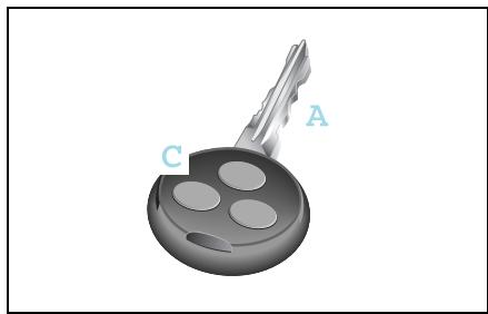
Your vehicle can be ordered with keys operated by radio or infrared remote control*.
Car key (A) with button for radio remote control (C).
>Note!
Should you have problems with your radio remote control in certain areas, please get in touch with a qualified specialist workshop such as a smart center.
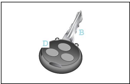
Car key (B) with button for infrared remote control* (D).
>Note!
Additionally, you receive a spare transmitter battery and a spare key.
>Note!
Unlocking and locking the driver and passenger doors can only be done using the radio remote control function on the ignition key.
Lost your car key?
You can get a spare key from a qualified specialist workshop (such as a smart center) following an identity check.
Unlocking and locking
Unlocking and locking the car from the outside

Accident risk!
When opening the doors, take care not to endanger other road users or necessitate other vehicles to swerve and potentially cause an accident. Make sure that nobody is endangered when opening the doors.
Unlock and lock the car in the following manner:
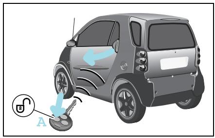
Unlocking the car with the remote control
Press button (A) once.
The turn signal lights flash once.
The car's doors can be opened.
>Note!
The remote control has an operating range of up to 15 metres. This can fluctuate greatly as a consequence of local conditions (reflective or absorbing objects) and interference emitted by other radio transmission systems. Similarly, the operating range fluctuates in line with the direction from which the remote control is activated.
Unlocking and locking
Locking the car with the remote control
Danger of injury! Never leave children unsupervised in the vehicle. They could open a locked door from the inside or start the vehicle if the key is left in it and thereby endanger themselves and others. You should therefore take the key with you when leaving the vehicle, even if you are only leaving it for a short time.
Do not leave children unsupervised in the car, even if they are secured by a child restraint system. Children could injure themselves on parts of the vehicle or be severely or even fatally harmed by prolonged exposure to intense heat or cold.
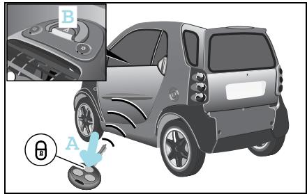
Close the car's doors.
Press button (A) once.
The turn signal lights flash three times.
The door lock display (B) flashes red. The exterior and interior lighting comes on and then goes off again after 12 seconds.
>Important!
Please make sure that you do not inadvertently activate the remote control.
The automatic locking functions
Auto-relock function
If you do not open either the driver or passenger door after unlocking the car with the remote control, the doors will be locked again automatically after one minute.
>Note!
Never leave your keys lying in the car.
You could lock yourself out!
Unlocking and locking
Drive lock function*
The vehicle doors are centrally locked from a speed of approximately 14km / h The drive lock function is switched off at delivery.
Switching on the drive lock function
Switch off the ignition.
Press the central locking switch and the locking button on the remote control device at the same time.
You will hear an acoustic signal. The drive lock function is switched on.
Switching off the drive lock function
Switch off the ignition.
Press the central locking switch and the unlocking button on the remote control at the same time.
You will hear an acoustic signal. The drive lock function is switched off.
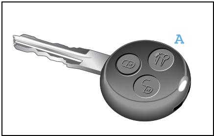
Opening and unlocking the sunroof top (smart cabrio only)
You can open the sunroof top of your vehicle from the outside by pressing button (A).
Convenience operation comprises the following functions:
- Complete opening of the sunroof top.
- Unlocking of the rear soft top.
- Unlocking of the rear soft top in its folded and locked position.
>Note!
For safety reasons, the sunroof top can only be closed using the switch on the inside of the vehicle.
>Important!
The remote control has an operating range of up to 15 metres (approx. 50 ft). Take care that you do not inadvertently open your car's sunroof top.
Unlocking and locking
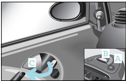
Locking and unlocking the car from the inside
How to lock the car from the inside
Press the central locking switch (A) for 2 seconds.
The central locking mechanism is distinctly heard.
The car is locked and will protect you against any unwanted persons entering the car when waiting, such as at traffic lights.
The door lock display (B) will flash red (if ignition is OFF).
If the vehicle will not lock using the remote control although the battery of the remote control has sufficient voltage:
Switch on the ignition.
Press the central locking switch (A) once.
The door lock display (B) will flash red for 5 seconds at double its normal frequency.
The car is locked if you switch the ignition off within this period of 5 seconds.
Remove the key and exit the vehicle with the key in your hand.
Close the driver door.
The car is now locked.
How to unlock the car from the inside
- You can unlock the doors by pulling the door handle (C).
If the driver door is open a warning signal will be sounded:
- if a gear is engaged while the engine is running and there is no pressure being applied to either the footbrake or the accelerator pedal.
- if the lights are switched on and the ignition is switched off.

Accident risk!
Do not leave children unsupervised in the vehicle. They could open a door from the inside - even if it is locked - and thereby endanger themselves or others.
Unlocking and locking
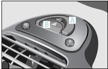
How to recognise when the transmitter battery in the key will soon be spent:
The turn signal lights flash 9 times in quick succession when you lock the car. Cause:
The remote control transmitter battery is almost spent.
You will be able to use the remote control approx. 100 more times.
Remedy:
Replace the transmitter battery1 or
Have the transmitter battery replaced by a qualified specialist workshop, such as a smart center.

Environment!
Always dispose of discharged
transmitter batteries in an environmentally-friendly manner.
>Note!
If you fail to replace the transmitter battery, after approximately 100 presses of the remote control
- you will not be able to lock or unlock the car.
- you will not be able to deactivate the electronic immobiliser.
- you will not be able to start the car.
you will, however, be able to unlock the central locking function by opening the tailgate with the car key.
If the vehicle will not lock using the remote control because the battery of the remote control is spent:
If you can no longer lock the car using the remote control and you do not have a spare transmitter battery on hand, please proceed as follows:
Open the driver door.
Turn the key in the ignition switch to position 0.
Press the central locking switch (A) until the door lock display (B) starts to flash.
Turn the key in the ignition switch to position 1 and then finally to position 0.
Take the keys out of the car with you and close the doors.
The car is now locked.
Unlocking and locking
Replacing the transmitter battery

Danger of poisoning!
Batteries contain toxic and caus
tic substances. For this reason, keep batteries away from children.
If a battery is swallowed, consult a doctor immediately.
Swallowing a transmitter battery can cause serious health problems.
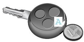
Use a coin to prise open the top half of the key casing (A).
>Note!
Replace the remote control's transmitter battery every 2 years at the latest.
Otherwise there is a danger of leakage! The remote control could be destroyed.
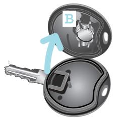
Take the transmitter battery (B) out of the board.
Insert the new transmitter battery, checking that the polarity is correct.
Type of battery: lithium cell CR 1225
>Note!
Check the polarity when inserting the new transmitter battery.
Otherwise damage may occur to parts in the electrical system.
Press both sides of the key casing back together again.
Adjusting the seats
Adjusting the seats
Adjust the driver seat to the correct position relative to the pedals and the steering wheel before starting a journey.

Accident risk!
Only adjust the driver seat while the vehicle is stationary. You will otherwise be distracted from the traffic situation and the movement of the seat could cause you to lose control of the vehicle and result in an accident.

Danger of injury!
When adjusting the seat, make sure that no one is trapped. Observe the notes on the airbag system.

Danger of injury!
To reduce the risk of serious or fatal injuries in an accident involving rapid deceleration, e.g. with an airbag inflating within a matter of milliseconds, or if the brakes are applied abruptly, please note the following:
- All vehicle occupants must select a seat position that allows the seat belt to be worn correctly and that is as far away from the airbag as possible.
The driver seat position must allow the driver to drive the vehicle safely. The driver's arms must be slightly bent when holding the steering wheel. The driver must maintain a distance from the pedals that allows him to depress these fully.
-
Move the front passenger seat as far back as possible, especially if a child is secured in a restraint system* on this seat.
-
Vehicle occupants should always wear their seat belt correctly and position their backrest as close to the vertical as possible. The head restraint should support the back of your head at about eye level.

Danger of injury!
Take the car to a qualified specialist workshop, e.g. a smart center if the seats have become damaged. The seat is an integral part of the car's safety system in the same way as e.g. seat belts and airbags. Its safety function can only be upheld if the seats are free of damage.
Adjusting the seats
Longitudinal seat adjustment

Accident risk!
Whenever the seat has been moved forward or back, ensure that it engages properly in position, as unexpected movement or adjustment of the seat while the car is being driven could cause the driver to lose control and result in an accident.

Danger of injury!
Do not insert your hands into the seat rail when adjusting the seat's longitudinal position. This represents a considerable risk of injury.
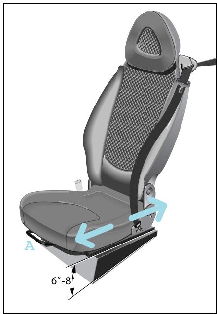
Pull up the handle (A).
Move the seat to the desired position.
Release the handle.
The locking mechanism must audibly engage on both sides.
Seat height adjustment
The seat guide is inclined in the horizontal plane. Longitudinal seat adjustment also alters the seat height.
Adjusting the seats
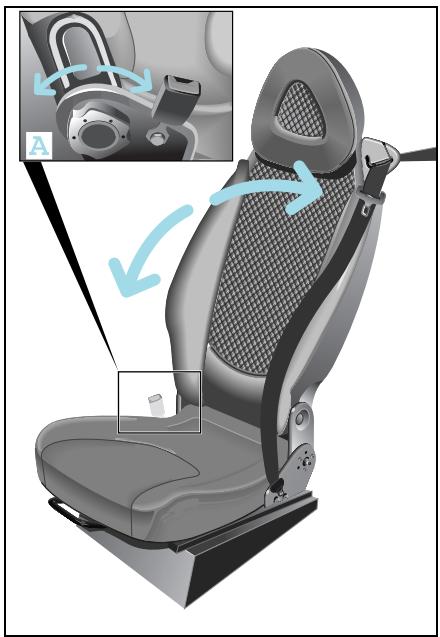
Adjusting the backrest inclination
■ Release the backrest.
Turn handwheel (A) forwards or backwards.
>Note!
Only the driver seat can be adjusted.
Adjusting the seats
Front passenger seat, folding down

Danger of injury!
Insert only suitable, sealed containers in the stowage compartment. Occupants otherwise could be injured by the receptacles or their contents in the event of an accident, a sudden braking manoeuvre or a rapid change of direction.

Danger of injury!
Do not place any hot beverages or glass bottles in the stowage compartment while driving. In the event of an accident, a sudden braking manoeuvre or a rapid change of direction,
- the hot beverage can be spilt and scald you and others,
glass bottles can be flung out and injure you and others.
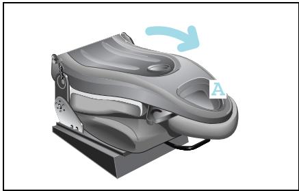
Once folded down, you can use the passenger seat
- as a storage space for small objects (A).
- as extra storage space.
>Note!
Please note the loading regulations (see page 199) contained in these operating instructions!
Adjusting the seats
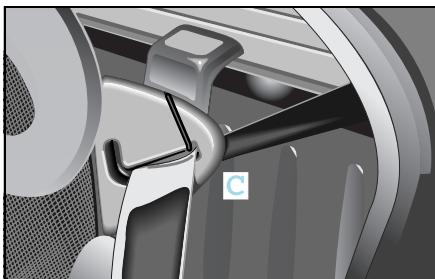
To fold the seat down:
Remove the seat belt from its belt guide (C).
- Slide the passenger seat into its centre position.
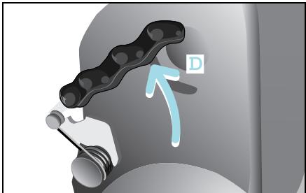
Press both levers (D) backwards at the same time.
The backrest will move forward a few millimetres out of its locked position.
■ Release both levers.
■ Fold the backrest forwards.
To fold back:
Pull backrest upwards and push it back into position until both levers audibly engage.
Place the seat belt back into the belt guide (C).

Danger of injury!
When returning the passenger
backrest to its upright position, please ensure that
- nobody becomes trapped,
- no obstacles are jammed in the lock,
- both levers audibly engage. Otherwise, in the event of an accident, a sudden application of the brakes or a rapid change of direction, the seat backrest may fail to prevent any objects stored in the luggage compartment from being propelled forwards, exposing the occupants to the risk of injury.
Mirrors, adjustment
Mirrors, adjustment

Accident risk!
The outside mirrors show objects reduced in size. The objects are closer than they appear. You could misinterpret the distance to vehicles behind you and cause an accident, e.g. when changing lanes. Therefore, ensure that you are aware of the actual distance to vehicles behind you by also looking over your shoulder.
Ensure that the outside and inside mirrors are correctly set before starting a journey. Only then can the driver be sure that the view to the rear is unobstructed.
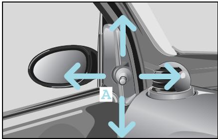
Manually adjustable outside mirror
Adjust the outside mirrors by turning lever (A).
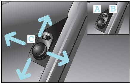
Electrically adjustable outside mirror* The control knob is located on the drive door.
The outside mirrors can be infinitely adjusted by swivelling the control knob (C).
Setting the adjustment side
Press the rocker switch.
- Driver side (A)
- Passenger side (B)
>Note!
The outside mirrors can only be adjusted when the ignition is switched on.
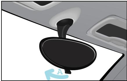
Adjusting the inside rearview mirror
Set the rearview mirror to the desired position by hand.
To avoid being distracted by oncoming traffic when driving at night:
- Deflect the inside rearview mirror by pulling lever (A).
The view to the rear is retained.
Power windows
Power windows
Opening and closing the side windows

Danger of injury!
Make sure that nobody can become
trapped as you close a side window. If there is a risk of trapping, press the switch to open the windows. Never leave children unsupervised in the vehicle. They could e.g. injure themselves by opening and closing the windows!
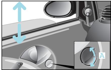
The side windows can be opened and closed by the electric power windows when the ignition is on.
To open
Press the rocker switch (A) downwards.
To close
Press the rocker switch (A) upwards.
>Note!
The windows do not close automatically when the car is locked.
Seat belts
The seat belts with integrated belt tensioners and belt force limiters combine with the airbags to form a restraint system that offers maximum safety in the event of an accident.

Danger of injury!
Airbags represent an additional form of protection but are no substitute for wearing a seat belt. To reduce the risk of serious or fatal injuries, make sure that all occupants – in particular, pregnant women – wear their seat belt correctly at all times, have adopted a normal sitting position, and that the seat is positioned as close to the vertical as possible.

Danger of injury!
A seat belt which is not worn, which is worn incorrectly, or which has not been engaged in the seat belt buckle correctly, cannot perform its intended protective function. Under certain circumstances this could even cause severe or fatal injuries. You should therefore make sure that all occupants - particularly pregnant women - are always wearing their seat belt correctly.
Make sure that the belt:
- runs over the hip bone as low down as possible, i.e. across the hip joint and not across the stomach.
- fits closely.
- is not twisted.
- runs across the middle of your shoulder.
- does not run across your neck or under your arm.
- fits closely across your pelvic area, by pulling upwards on the shoulder section of the belt.
Do not secure any objects with a seat belt if it is being used by one of the vehicle's occupants.
Avoid wearing bulky clothing, e.g. a winter coat.
Do not position the belt strap across sharp-edged or fragile objects, especially if these are located on or in your clothing, e.g. spectacles, pencils or keys. The seat belt strap could be damaged and you could be injured.
Only one person should use each seat belt at any one time.
On no account should children travel sitting on the lap of another occupant. It would not be possible to restrain the child, and the child or other vehicle occupants could be injured seriously in the event of abrupt braking or even fatally in the event of an accident.
Seat belts

Danger of injury!
Persons under 1.50m in height and children under twelve years of age cannot fasten the seat belts properly. They therefore require additional suitable restraint systems on appropriate seats for protection in an accident. Always follow the manufacturer's installation instructions when fitting a child restraint system*.

Danger of injury!
A seat belt only offers its intended degree of protection if the backrest is positioned as close to the vertical as possible and the occupant is sitting upright. Avoid seat positions that prevent the seat belt from lying correctly across the wearer's body. Position the backrest as vertically as possible. Do not drive with the backrest reclined too far back. Otherwise, you could be seriously or even fatally injured in the event of an accident or sudden braking.

Danger of injury!
Modifications to or work not performed correctly on restraint systems (seat belts, anchorages, belt tensioners, belt force limiters or airbags) or their wiring, as well as work on other networked electronic systems, may prevent the restraint systems from working correctly. Airbags or belt tensioners could e.g. fail to operate in accidents where the rate of deceleration exceeds the tripping threshold, or be activated unintentionally. Never carry out any modifications on the restraint systems. Never tamper with electronic components and their software.

Danger of injury!
The seat belt cannot function correctly if the belt or buckle is dirty or damaged. Keep the belt and buckle clean, otherwise the belt tongue cannot engage correctly.
Check the seat belts regularly to ensure that
- they are not damaged,
- they are not running across sharp edges,
- are not trapped.
Otherwise the belt could tear in the event of an accident. You or others could be seriously or fatally injured. Have seat belts which have been damaged or subjected to heavy loads in an accident replaced and have their anchorages checked.
For safety reasons,smart gmbh recommends using only seat belts that smart gmbh has specifically approved for your vehicle.
Seat belts

Seat belt height adjustment
The car has three-stage seat belt height adjustment capability integrated into the seat.
The seat belt can run
- through the belt guide (A),
- above the belt guide,
- below the belt guide.
>Note!
If the seat belt is to be run above or below the seat belt guide, the belt must be taken out of the guide.
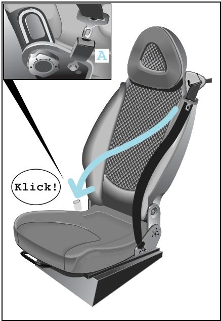
Putting on the seat belts
Take a seat.
Pull the seat belt without jerking it from the roller.
Pull the belt across your shoulder.
Your back must be leaning against the backrest.
- Click the seat belt into the buckle (A).
Taking off the seat belts
Press the red button on the belt buckle.
Let the belt run back into the belt guide.
The belt is automatically reeled back into the roller.
Belt tensioners and belt force limiters
Belt tensioners and belt force limiters
The seat belts are equipped with belt tensioners, a belt force limiter, the functions of which are explained below.
Belt tensioners
- tension the seat belts when activated, so that they lie tightly across the body.
- are only triggered in collisions with high vehicle deceleration/acceleration in the longitudinal direction, e.g. a head-on collision.
If the airbag indicator light comes on, your belt tensioner has been activated.
>Note!
Do not fasten the seat belt on the front passenger side if it is not occupied. In the event of an accident, the belt tensioner would be triggered unnecessarily.
>Note!
Belt tensioners cannot compensate for:
- incorrect seated positions,
- seat belts worn incorrectly.
Belt tensioners do not actively pull the occupants back against the seat backrests.
Belt force limiters
- reduce the force exerted by the belt on the occupants when activated in the event of an accident.
The belt force limiter is designed to operate in unison with the front airbag, which absorbs a portion of the seat belt's decelerating forces, distributing the load over a larger area.
If the ignition is switched on, the belt tensioner is activated:
- if the restraint systems are operational.
- for each three-point seat belt that is fastened properly.
- in the event of a head-on or rear-end collision if the vehicle is decelerated or accelerated sufficiently in the longitudinal direction at the start of impact.
- in certain rollover situations if the need for additional protection is detected.
Belt tensioners and belt force limiters
If the belt tensioners are triggered, you will hear a loud noise that fundamentally represents no risk to your hearing. Some dust may be generated.

Danger of injury!
Have belt tensioners which have been triggered replaced at a qualified specialist workshop which has the necessary specialist knowledge and tools to carry out the work required. smart gmbh recommends that you visit a smart center for this. In particular, work relevant to safety or on safety-related systems must be carried out at a qualified specialist workshop.
Comply with safety regulations when disposing of belt tensioners. These regulations can be viewed in every qualified specialist workshop such as a smart center.
Cockpit, left-hand drive model
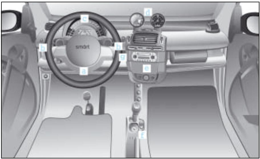
Cockpit, left-hand drive model
a Gearshifts from the steering wheel*
b Control lever
c Instrument cluster
d Upper centre console
e Lower centre console
f Shift lever console
g AUX jack
Cockpit, right-hand drive model
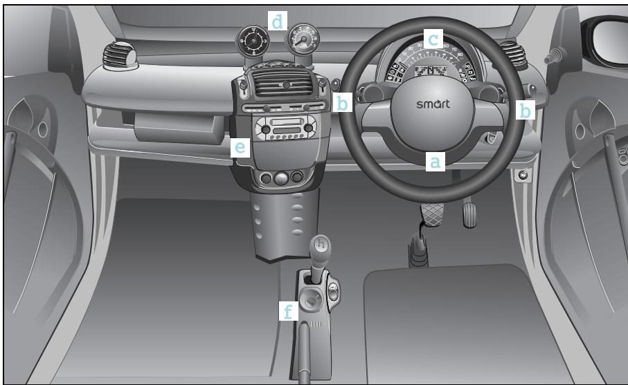
Cockpit, right-hand drive model
a Gearshifts from the steering wheel*
b Control lever
c Instrument cluster
d Upper centre console
e Lower centre console
f Shift lever console
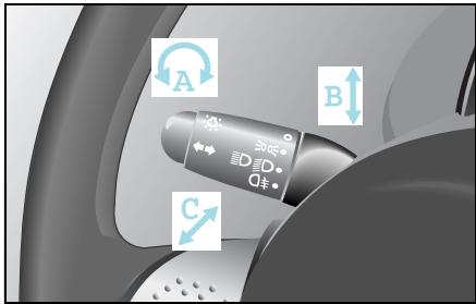
Control levers left
A Lights
0 = off, 1 = parking lights, 2 = low beam lights,
3 = rear fog lamp
B Turn signal lights
Indicating a right or left turn
C Main-beam headlamps
1 = high beam lights, 0 = off, - 1 = headlight flashers
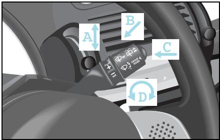
Control lever right
A Wipe windscreen
2 = wiper speed stage 2, 1 = wiper speed stage 1, 0 = off,
-1 = interval wiping
B Wiping and washing windows
2 = rear window washing, 1 = rear window interval wiping, 0 = off, -1 = windscreen washing
C Switching the cruise control and limiter on/off
D Cruise control and limiter functions
Instrument cluster, left-hand drive model
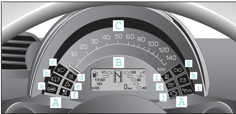
Instrument cluster, left-hand drive model
A Indicator lights
B Display
C Speedometer
Indicator lights
Brake system (b)
High beams (c)
Rear fog lamp (d)
A esp (e)
Airbag (f)
Turn signal lights (g)
Battery (h)
Oil pressure (i)
Engine check (j)
Diesel engine preheating1 (k)
Heater booster1 (l)
Instrument cluster, right-hand drive model
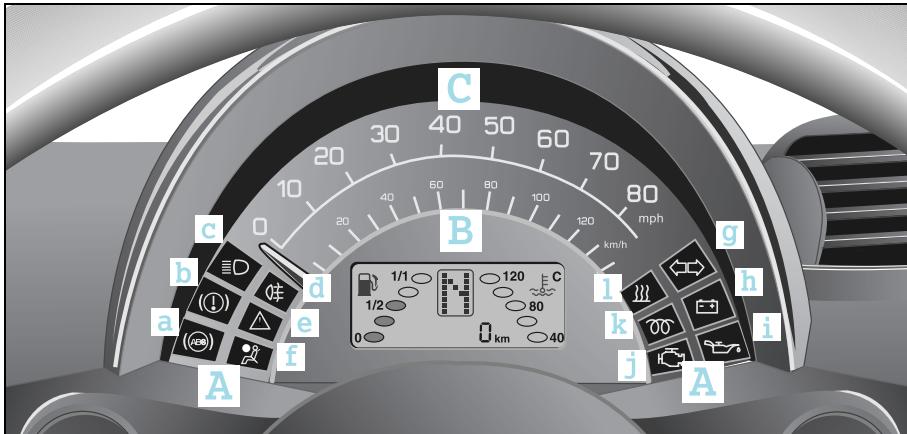
Instrument cluster, right-hand drive model
A Indicator lights
B Display
C Speedometer
Indicator lights
Brake system (b)
High beams (c)
Rear fog lamp (d)
A esp (e)
Airbag (f)
Turn signal lights (g)
Battery (h)
Oil pressure (i)
Engine check (j)
Diesel engine preheating1 (k)
Heater booster1 (l)
Instrument cluster
Instrument cluster
abs indicator light
It lights up:
- when the ignition is switched on (self diagnosis).
The light goes out after engine is started or
goes out after no more than 10 seconds.

abs indicator light

Accident risk!
If the abs system is faulty, the wheels could lock when the brakes are applied. This limits the steerability of the vehicle when braking and the braking distance may increase. If abs is deactivated due to a fault, then esp is also deactivated.
The risk of your vehicle skidding is then increased in certain situations. You should therefore always adapt your driving style to suit the prevailing road and weather conditions.
abs indicator light
- in abs limp home mode (fault in the abs system).
Take the car to a qualified specialist workshop, e.g. a smart center, without delay.
- when the abs system fails, together with the brake system indicator light.
- Immediately park your car away from moving traffic.
- When you exit the vehicle, secure it against rolling away with the handbrake.
Do not drive any further.
Call a breakdown recovery service such as smartmove Assistance or a qualified specialist workshop such as a smart center.

Brake system indicator light
It lights up:
- when the ignition is switched on.
The light goes out after the engine starts or
goes out after no more than 10 seconds.
- with handbrake applied.

Brake system indicator light
It lights up:
- when brake circuit fails or brake fluid level is too low.
- Immediately park your car away from moving traffic.
- When you exit the vehicle, secure it against rolling away with the handbrake.
Do not drive any further.
- Call a breakdown recovery service such as smartmove Assistance or a qualified specialist workshop such as a smart center.
- when the abs system malfunctions, together with abs indicator light.
Take the car to a qualified specialist workshop, e.g. a smart center, without delay.
High beam indicator light
It lights up:
- when high beam headlights are on.
- when the headlight flashers are used.
Instrument cluster
Rear fog lamp indicator light
It lights up:
- when the rear fog lamp is switched on.

esp indicator light
It flashes:
when esp actively intervenes.
Light stays on permanently:
for system failure,
when esp is not responding.
It may be possible to clear a system malfunction by restarting the car.
If the indicator light still does not go out, take the car to a qualified specialist workshop, e.g. a smart center, without delay.
>Note!
The operating principle of esp and additional information to this regard can be found on page 165.

esp indicator light

Accident risk!
If esp is no longer functioning, there is a greater risk that your car could skid in certain driving situations. You should therefore always adapt your driving style to suit the prevailing road and weather conditions.

Airbag indicator light
The airbag indicator light signals to you that there is a fault in the safety systems of the:
Airbags
- Belt tensioners
- Child seat recognition system
>Note!
The operating principle of the airbags and additional information to this regard can be found starting on page 166.

Airbag indicator light
Danger of injury! If the indicator light does not come on when you switch on the ignition or does not go out again after a few seconds once the engine is running or comes on again, there is a fault. Some systems could be triggered unintentionally or not be triggered at all in the event of an accident with high deceleration. In such cases, immediately have the safety system of your vehicle checked and repaired at a qualified specialist workshop which has the necessary specialist knowledge and tools to carry out the work required. smart gmbh recommends that you visit a smart center for this. It is particularly important to have safety-relevant work and work on safety-relevant systems performed by a qualified specialist workshop.

Airbag indicator light
It lights up:
- with the ignition switched on.
The subsequent self-diagnosis of the safety systems yields the following results:
- Airbag indicator light goes out after a maximum of 4 seconds:
No fault detected.
The airbag system is OK.
- The airbag indicator light goes out after a maximum of 4 seconds for approximately 1 second, then it comes on again and stays on:
A fault has been detected.
Do not sit on the passenger seat; this applies in particular to children secured by a rearward-facing child restraint system.
Take the car to a qualified specialist workshop, e.g. a smart center, without delay.
Instrument cluster

Airbag indicator light
- The airbag indicator light flashes for 15 seconds, then illuminates permanently:
smart baby carrier (original smart accessory) identified on the passenger seat.
Passenger airbag and the side airbags* (if available) are deactivated.
- Airbag indicator light flashes permanently:
Fault with child seat recognition system.
Do not sit on the passenger seat; this applies in particular to children secured by a rearward-facing child restraint system.
Take the car to a qualified specialist workshop, e.g. a smart center, without delay.

Airbag indicator light
Danger of injury! If the airbag indicator light does not come on when a smart baby carrier is fitted to the passenger seat, the passenger airbag has not been deactivated. This can result in the child becoming seriously to fatally injured in the event of an accident when the passenger airbag is triggered, especially if the child is in the direct vicinity of the passenger airbag at the time the airbag is triggered.
The passenger airbag is only deactivated when you fit an original smart baby carrier to the passenger's seat.
Danger of injury! If the passenger airbag is activated, e.g. the airbag indicator light does not illuminate, you must never secure a child on the passenger seat in a rearward-facing child restraint system.
Also observe the corresponding warning sticker on the instrument panel. If you have installed a special smart baby carrier on the passenger seat and the airbag indicator light does not illuminate (restraint system not detected), have the automatic restraint system detection checked by a qualified specialist workshop which has the necessary specialist knowledge and tools to carry out the required work. smart gmbh recommends that you visit a smart center for this.
Until this problem has been rectified, do not carry children in the car, as they could sustain serious or even fatal injuries in the event of an accident.

Turn signal indicator light
It flashes:
- when ignition is switched on, if:
the indicator lever is activated.
the hazard warning lights are switched on.
>Note!
If a turn signal light malfunctions, the flashing frequency is doubled.
Replace the bulb (see page 232) or
Take the car to a qualified specialist workshop, e.g. a smart center.

Battery indicator light
It lights up:
- when the ignition is switched on.
The indicator light goes out if the engine is running.
If it comes on during a journey or fails to go out after the engine has been started, the battery is not being charged.
- Immediately park your car away from moving traffic.
- When you exit the vehicle, secure it against rolling away with the handbrake.
Do not drive any further.
Call a breakdown recovery service such as smartmove Assistance or a qualified specialist workshop such as a smart center.
>Important!
The drive belt may have broken.
If this occurs, the engine may suffer damage if driven any further.
Oil pressure indicator light
It lights up:
- when the ignition is switched on.
Indicator light goes out if the engine is started and oil pressure is sufficient.
Beware of the following!
- If the indicator light goes out before the engine is started, it is not functioning.
Check the oil level.
Take the car to a qualified specialist workshop, e.g. a smart center.
Instrument cluster
Oil pressure indicator light
>Important!
Continue to drive the car or keeping the engine running may lead to the engine being destroyed.
>Note!
The oil pressure indicator light is a warning light that displays low oil pressure. Check your engine's oil level at regular intervals (see page 206).

Preglow indicator light
It lights up:
- when the ignition is switched on.
When the indicator light extinguishes, the engine is ready to be started.
>Note!
If the engine is already at operating temperature you can start it without the pre-heater.
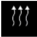
Heater booster indicator light
>Note!
The heater booster can only be switched on if the engine is running.
It lights up:
- when the heater booster is switched on.
In order to switch on the heater booster you must move the air temperature slider as far to the right as it will go.
It goes out:
- when the heater booster is switched off.
In order to switch off the heater booster you must move the air temperature slider to the left.
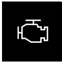
Engine check indicator light
It lights up:
- when the ignition is switched on.
Indicator light goes out after the engine is started or after 10 seconds if the engine electronics are functioning properly.
If it comes on during a journey:
Take the car to a qualified specialist workshop, e.g. a smart center, without delay.
Instrument cluster
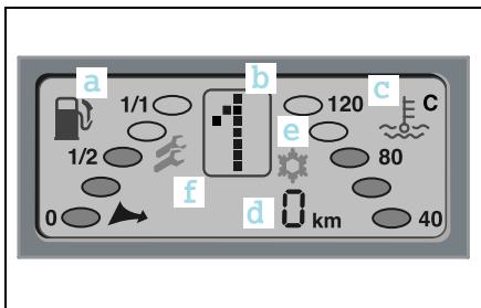
Display
You can see the following in the display:
(a) Fuel tank gauge
(b) Gearshift indicator or automatic display/electronic immobiliser
(c) Coolant temperature display
(d) Multiple display with tank capacity residual litre indicator
(e) Frost warning*
(f) Service interval display
Display illumination
The display illumination lights up:
- when the lights are switched on.
- when the ignition is switched on.
Display illumination goes out when the ignition and the lights are switched off.
>Note!
Display illumination is dimmed if the lights are switched on along with the ignition.
Instrument cluster
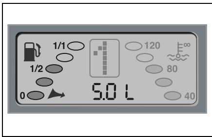
Fuel tank gauge
The tank's fuel level is displayed with the aid of five oval-shaped segments.
The number of shaded segments indicates the level of fuel in the tank.
If all five segments are dark, the tank is full.
Reserve range
You are in the reserve range if there are no more than 5 litres of fuel in the tank. If this occurs,
- the fuel pump symbol and the residual litres arrow start to flash,
- the multi-function display shows the fuel tank capacity with an accuracy of 0.5 litres (residual litres display),
- you should call at the next nearest filling station.
>Notes on the residual litres display!
The residual litres display is only active in the reserve range.
The switchover function of the multifunction display (see page 48) remains active.
If all 5 segments are flashing, there is a problem in transferring the fill level information.
Find a filling station, completely refuel the vehicle and drive according to the odometer.
Take the car to a qualified specialist workshop, e.g. a smart center.
Instrument cluster
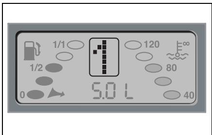
Digital gear indicator
The gear indicator displays information on the sequential transmission:
Gear engaged
Activated electronic immobiliser (see page 140 ff)
Upshift
Downshift
Neutral, no gear engaged
Reverse gear is engaged
No gear engaged
Shifting system fault
Automatic mode
CAN (data bus) malfunction (icon flashes)
Rear soft top' not correctly locked in place
1 Only for the smartfortwo cabrio.
Instrument cluster
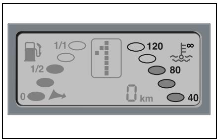
Coolant temperature gauge
The coolant temperature is displayed by 5 oval-shaped elements.
The number of shaded elements indicate the coolant temperature.
- At normal operating temperature, three segments are shaded.
The coolant temperature is at least 80^ .
-
If 5 segments are dark, then the ^ C symbol starts to flash.
-
Immediately park your car away from moving traffic.
-
Secure your car against rolling away if you have to leave it.
Do not drive any further.
Call a breakdown recovery service such as smartmove Assistance or a qualified specialist workshop such as a smart center.
-
If the temperature continues to increase, the 5 segments will also start to flash after 15 seconds.
Avoid driving at high engine speeds and do not drive fast.
- Immediately park your car away from moving traffic.
- Secure your car against rolling away if you have to leave it.
Do not drive any further.
Call a breakdown recovery service such as smartmove Assistance or a qualified specialist workshop such as a smart center.
>Important!
Continue to drive the car or keeping the engine running may lead to the engine being destroyed.
Instrument cluster
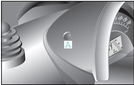
Multi-function display
In each case press button (A) once to switch between the following functions:
- Trip odometer
- Daily trip odometer (when held down for a few seconds it returns to zero)
- Outside temperature*
- Residual litres display (when there are fewer than 5 litres of fuel in the fuel tank)
>Note on outside temperature display*
The temperature display will respond sluggishly when temperatures rapidly rise or fall.
This ensures that the temperature reading is not falsified by the heat of the engine e.g. when the car is at a standstill or travelling relatively slowly.
Frost warning*

Accident risk!
Even if the temperature is slightly above freezing, there could still be ice on the road, particularly in wooded areas and on bridges. The vehicle could skid if you fail to adapt your driving style. You should therefore always adapt your driving style and speed to suit the weather conditions.
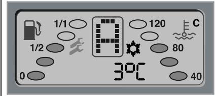
If the outside temperature falls below 3
^ C , the display alerts you to the fact that there could be ice on the road.
The outside temperature appears in the display.
A snowflake symbol flashes for 60 seconds in the display.
Instrument cluster
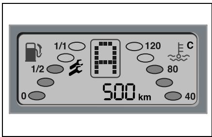
Service interval display
The service interval display informs you of the point in time and scope of the next service visit.
An upcoming service visit is shown in the display approximately one month in advance. After the engine is started, this information is shown in kilometres (km) or in days for approximately 10 seconds, depending on the kilometre reading.
One spanner or two spanners ±b is/are shown in the display, depending on if service A or B is due.
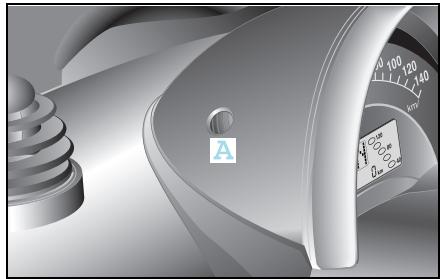
Activate service interval display
■ Briefly press button (A) on the multifunction display twice.
Upper centre console
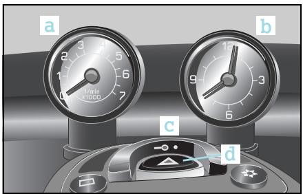

Upper centre console
a Tachometer*
b Cockpit clock*
c Central locking switch
d Hazard warning lamps
e Rear window heater
f Driver's heated seat
g Passenger's heated seat
h Air conditioning plus*
1 Only for the smart fourwo coupé.
Upper centre console
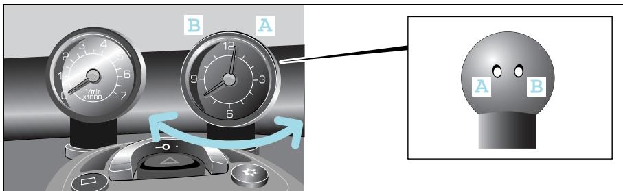
Cockpit clock*
Setting the time
The buttons for setting the time are located on the rear of the cockpit clock.
Advancing the time
Press button (A) once.
The time displayed changes by one minute.
Press button (A) for more than 2 seconds.
The speed at which the time changes accelerates.
Reversing the time
Press button (B) once.
The time displayed changes by one minute.
Press button (B) for more than 2 seconds.
The speed at which the time changes accelerates.
The cockpit clock can be adapted to suit your needs
Your cockpit clock
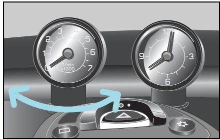
- can be turned through approx. 90^ .
This ensures that you or the person sitting next to you has an ideal view of the clock.
- is backlit the moment you switch your car's lights on.
This enables you to see the display at all times, even when it is dark outside.
>Note!
Do not hang any objects on the cockpit clock.
This could cause the clock to tear out of its mounting and badly damage it.
Upper centre console
Tachometer*
Driving in the optimum engine speed range helps you to
save fuel.
- take good care of the engine.
>Important!
Always pay attention to the gear shift recommendations indicated in your car's gear indicator.
>Important!
For safety reasons, no conversions may be made to the tachometer.
>Note!
Do not hang any objects on the tachometer.
This could cause the tachometer to be torn from its mountings and badly damage it.
The tachometer can be adapted to suit your needs
Your tachometer
- can be turned through approx. 90^ .
This gives you an ideal view of the instrument, no matter how your seat is positioned.
- is backlit the moment you switch your car's lights on.
This enables you to see the display at all times, even when it is dark outside.
Upper centre console
Function
The tachometer displays the engine speed in units of 1,000 rpm.
| The optimum engine speed ranges (rpm) are: | Petrol engines | Diesel engines |
| Driving off | 1,000 – 2,000 | 1,000 – 2,000 |
| Normal operation at constant speed | 2,000 – 3,000 | 1,800 – 3,000 |
| Brief periods of acceleration, e.g. when passing | 3,000 – 6,300 | 3,000 – 4,400 |
Lower centre console
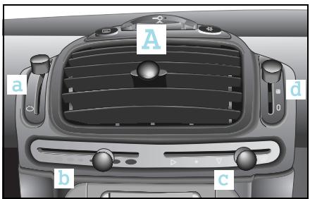
A Heater/ventilation
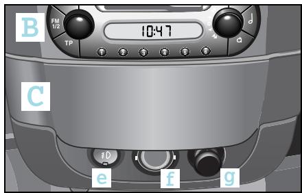
B Audio/telematics devices
C Storage compartment
a Fresh air/recirculated air selector
b Air temperature/heater/heatber booster
c Air distribution
d Blower
e Front fog lamps*
f Interior light
g 12-volt power socket
1 Only for vehicles with a diesel engine.
Shift lever console

Shift lever console
a Telephone console*
b Gearshift lever
c Power glass sliding roof switch*1 or rear soft top switch2
d Ignition switch
1 With the fourwo coupé
2 With the fourwo cabrio
Contents
Lights. 58
Headlight range control. 61
Interior lights 62
Fog lamps 63
Turn signal lights. 65
Warning sounds and indicator lights 66
>>Light conditions.
As your vehicle is easy to operate because all control elements are located where you would expect them to be, even navigating in the dark is a cinch. But go ahead and try it out in daylight first.
Lights
Lights

Accident risk!
Switch your lights on in good
time
- when it is raining heavily,
- when it starts to get dark.
Vehicles are detected easier in traffic
if they have their lights on.
Switching on the lights
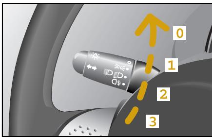
The control lever for the lights is located to the left of the steering wheel.
By turning the rotary control from its default position of 0, the following occurs:
Stage 1 - the parking lights are switched on.
Stage 2 - low beam lights are switched on.
Stage 3 - the rear fog lamp and the low beam lights are switched on.
>Note!
When you switch the ignition off, the low beam lights are also switched off. They come on again automatically when the engine is restarted.
>Note!
If you drive in countries in which the side of the road driven on is opposite that of the country in which the vehicle is approved, oncoming traffic may be blinded by the asymmetric low beam lights. In this case, have the headlights converted to the symmetric low beam lights for these countries. This conversion can be carried out in a qualified specialist workshop such as a smart center.
High beam lights
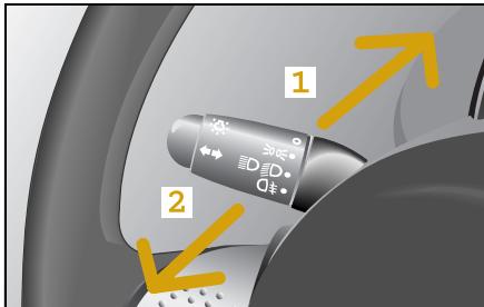
The high beam lights can only be switched on if
- the ignition is turned over.
- the rotary control is turned to at least stage 2 (low beam lights).
Switching on the high beam lights
Press the lever away from the steering wheel (1).
The lever engages.
Switching off the high beam lights
Pull the lever towards the steering wheel (2).
The lever is back in its default position.
Coming home function*
The coming home function allows you to switch on your car's lights and the interior lighting if the vehicle is parked in a dark area or you are approaching it. 12 seconds is the time the lights on your vehicle will stay on to help you find your way.
When leaving the car
Remove the ignition key.
■ Briefly press the locking button on the remote control twice in succession.
The car is locked.
The driving lights are switched on automatically and go out again after 12 seconds.
Upon returning to the car
■ Briefly press the unlocking button on the remote control twice in succession.
The car is unlocked.
The car's exterior and interior lights comes on and then go off again after 12 seconds.
Lights
Daytime driving lights*
If your car is equipped with daytime driving lights, the low beam and parking lights come on automatically when you drive off.
>Note!
When the daytime driving lights are activated, the high beam lights can only be turned on when the light control lever is in stage 2 (low beam lights).
Switching off daytime driving lights
Switch off the ignition.
Operate the headlight flashers.
At the same time press the button for unlocking the car on the car key.
A signal sounds by way of confirmation that the daytime driving lights are switched off.
Switching on daytime driving lights
Switch off the ignition.
Operate the headlight flashers.
At the same time, press the button for locking the car on the car key.
A signal sounds by way of confirmation that the daytime driving lights are switched on.
1 Standard specification in countries where daytime driving lights are required by law.
Headlight range control
Headlight range control
The headlight range adjustment enables you to adapt the headlights to suit the load status of your car.
Adjusting the headlight range
The basic setting, this means:
- no payload,
- driver seat occupied,
- headlight range adjustment position 0
ensures that you
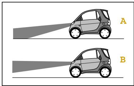
- obtain the best possible visibility conditions for the driver (A),
- do not dazzle drivers of oncoming vehicles.
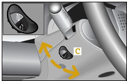
If the light cone changes due to the vehicle load (B):
Turn the headlight range adjuster wheel (C) to the corresponding position until the basic light position setting is re-established.
>Note!
Note that the headlight range adjustment must be reset to position 0 after you have unloaded the vehicle.
| Switch position | Load |
| 0 | Driver seat occupied. |
| Driver and passenger seats occupied. |
| 1 | Driver seat occupied and maximum load in the luggage compartment (50 kg). |
| 2 | Driver seat, passenger seat occupied and maximum payload in the luggage compartment (50 kg). |
Interior lights
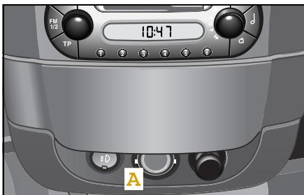
Interior lights
The interior lights are located on the
centre console (A).
- at the rear of the car (B).
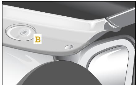
The interior lights both illuminate briefly when you open the doors. The lights go off
- immediately after the ignition is switched off if all doors are closed.
- after 15 seconds, if all doors are closed.
- after 10 minutes if at least one door is open.
The lights also illuminate when you lock or unlock the car with the remote control. The lights go off
- immediately after the ignition is switched on.
- after 30 seconds.
Both lights continuously illuminate when you press the toggle switch-type interior light (A) on the lower edge.
The lights go off when you press the toggle switch on the upper edge.
>Important!
When leaving the car, make sure that
- the interior lights are not set to permanent operation.
- one of the doors is not left open for longer.
This could cause car's battery to run flat.
Fog lamps
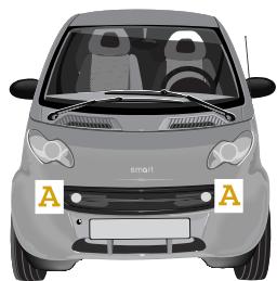
Front fog lamps*
The front fog lamps (A) should only be switched on
-in fog
- where visibility is poor because of rain, or
- where vision is impaired because of snow.

Accident risk!
Adapt your speed and driving style according to the visibility conditions. Other vehicles could be driving only a short distance in front of you without you being able to spot them in good time and brake.
Switching on the fog lamps
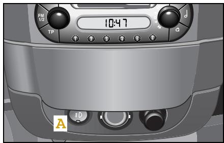
The front fog lamps can only be switched on if the parking lights are already on.
Press switch (A) once.
The following lights are switched on:
- the fog lamps
- the integrated indicator light
>Note!
Please observe the national statutory regulations regarding the use of front fog lamps.
Switching off the fog lamps
Press switch (A) again.
>Note!
If you switch the lights off, the fog lamps are also switched off. Switching the lights back on again does not automatically switch the fog lamps on.
Fog lamps
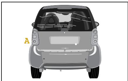
Rear fog lamp
The control lever for the rear fog lamp (A) is located to the left of the steering wheel.

Accident risk!
The rear fog lamp should only be switched on when visibility is down to less than 50 metres. Vehicles following behind may otherwise be dazzled.
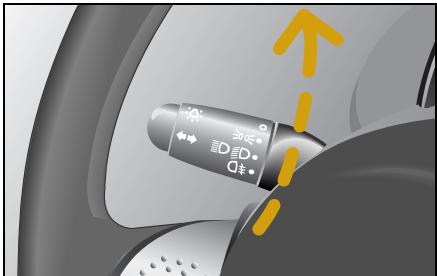
Switching on the rear fog lamp
Turn the rotary control to the rear fog lamp icon (stage 3).
When the ignition is switched on, the following lights also come on:
- The rear fog lamp
- The indicator light in the display
Switching off the rear fog lamp
Turn the rotary control to stage 0.
>Important!
Turn it back by one stage only if you wish to continue driving with low beam lights on.
Turn signal lights
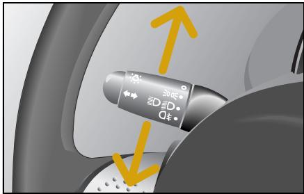
Turn signal lights
The turn signal light control lever is located to the left of the steering wheel.
To signal turning right
Push it further upwards until you feel it lock into place.
To signal turning left
Push it further downwards and allow it to lock into place.
>Note!
The lever which is locked in place is then returned to the neutral position
- after turning.
- via the automatic turn signal reset function.
The control lever can also be returned to its neutral position manually.
Turn signal lights with convenience touch-shifting
If you briefly press the control lever up or down, the turn signal lights flash three times on the corresponding side of the car.
Warning sounds and indicator lights

Warning sounds and indicator lights
Horn
Press anywhere on the steering wheel's highlighted area.
The horn sounds.
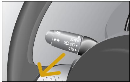
Headlight flashers
The control lever for the headlight flashers is located to the left of the steering wheel.
The headlight flashers remain active for as long as the lever is pulled in towards the steering wheel.
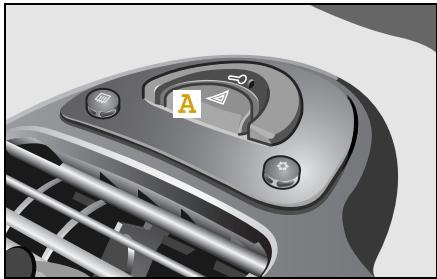
Hazard warning lights
To switch the hazard warning lights on, press the red switch (A).
This causes
- all six turn signal lights to flash,
- the turn signal indicator light to start flashing when the ignition is switched on, and
- the hazard warning light switch also to flash.
To switch the hazard warning lights off, press the red switch again.
Contents
Audio/telematics devices*. 68
smart radio one* 69
smart radio three* 70
smart radio five* 71
smart radio navigator* 72
smart CD changer* 76
CD box* 77
Cassette box*.80
Telephone console* .83
Universal hands-free system*. .86
ipod*.87
smart sound package* .88
>>Communication.
Your car is quite an entertaining vehicle in and of itself. However, should you prefer a little more variety while on the move, you can listen to the radio, a cassette or CD.
These systems transform your car into an all-round entertainer.
Audio/telematics devices*
Audio/telematics devices*

Accident risk!
Acquaint yourself with the various functions of your audio, navigation and telecommunications systems prior to starting out on your journey to ensure that you are not distracted in any way from events on the road if you operate them while driving.
For safety reasons, only operate the system when the vehicle is stopped and if traffic conditions permit.

Accident risk!
Always select a volume that allows you to still hear ambient sound in your immediate vicinity (e.g. horns, emergency rescue vehicles, police vehicles, etc.). You could otherwise cause an accident.

Accident risk!
If you wish to have a radio other than an original smart radio fitted in your car, please always have the necessary work performed by a qualified specialist workshop, such as a smart center.
This is particularly important if there had already been fitted a smart radio five or if your car has a radio preinstallation.
If a radio is connected up inexpertly, important vehicle functions could fail.
On the following pages you will find a brief description of the audio, navigation and telecommunications systems that are available for your smart fortno coupé and smart fortno cabrio.
The devices are described with their full complement of equipment, including radio, cassette, and CD changer* modes. The description for your individual equipment specification applies.
Please see the individual operating instructions for detailed functions.
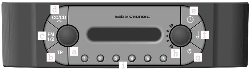
smart radio one*
Basic settings
- Switch on/off, change volume (a)
- TP on/off (b)
- Clock (e)
- Tone settings (f) changeable with button (h)
- EXPERT settings (g)
Radio mode
- Select transmitter, store station (i)
- Station search (c)
- Station storing levels (FM1/FM2) (c) with six memory slots per level (callable by button (i))
CD mode
- Selector button, CD mode (d)
- Scan tracks (h)
- Select CD (i)
- Select track (h)
-Play tracks in random order (h)
smart radio three*
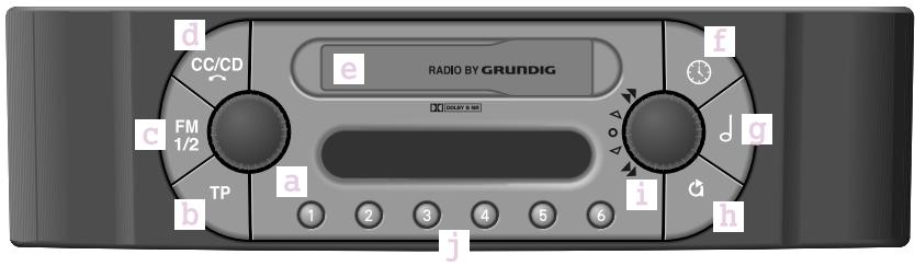
smart radio three*
Basic settings
- Switch on/off, change volume (a)
- TP on/off (b)
- Clock (f)
- Tone settings (g) changeable with button (i)
- EXPERT settings (h)
Radio mode
- Select transmitter, store station (j)
- Station search (c)
- Station storing levels (FM1/FM2) (c) with six memory slots per level (callable by button (i))
Cassette mode
- Selector button for cassette, CD mode/eject cassette (d)
- Cassette compartment (e)
- Scan tracks (i)
- Briefly turn (i) to switch to other side of cassette
- Turn (i) for forward and reverse
CD mode
- Selector button for cassette, CD mode/eject cassette (d)
- Scan tracks (i)
- Select CD (j)
- Select track (i)
- Play tracks in random order (i)
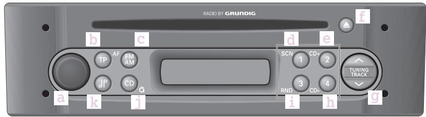
smart radio five*
Basic settings
- Switch on/off, change volume (a)
- TP on/off (b)
- EXPERT settings (by pressing and holding) (j)
- Tone settings (k) changeable with button (g)
Radio mode
- Select station button, store station (d, e, h, i)
- Station search (g)
- Station storing levels (AM/FM1/FM2/FM3) (c) with four memory slots per level (callable by buttons (d,e,h,i)
CD mode
- Scan tracks (d)
- Select CD (e, h)
- Eject CD (f)
- Select track (g)
-Play tracks in random order (i)
smart radio navigator*
smart radio navigator*

Accident risk!
Acquaint yourself with the various functions of your smart navigation system prior to starting out on your journey to ensure that you are not distracted in any way from events on the road if you operate it while driving. For safety reasons, only operate the system when the vehicle is stopped and if traffic conditions permit.
The smart navigation system offers
- radio functions (VHF, short wave, medium wave and long wave reception),
- a CD player which plays audio CDs, and an
- integrated navigation system with simultaneous use of audio and navigation functions.
CD drive
Audio CDs and the data media for the navigation system are played on the integrated CD drive.
Multi-function display
The multi-function display serves to visualise the main functions with directional arrows, letters, distance data and schematic intersection displays. Voice information supports the visual displays and also helps you to arrive at your destination quickly and without any problems.
>Note!
More detailed information on the navigation system functions can be found in the operating instructions for your smart navigation system.

Accident risk!
Always select a volume that allows you to still hear ambient sound in your immediate vicinity (e.g. horns, emergency rescue vehicles, police vehicles, etc.). You could otherwise cause an accident.
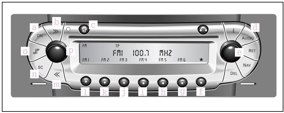
Radio control elements
a Switching device on or off
b Automatic forward search function
c Mute switch
d Radio or CD player select
e Manual station setting and setting ofbass, treble, fader and balance
f Menu change
g Station memory and autostore function
h Station memory
i Station memory, PTY+ search and manual search run
j Station memory and PTY- search
k Station memory and regional mode
1 Station memory and switch-over to RDS/ frequency mode
m Automatic reverse search run
n Scan search function Briefly plays receivable radio stations
o Selection: Bass, treble, fader, balance
p Volume control
smart radio navigator*
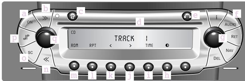
CD control elements
a Switching device on or off
b Skip track, forward
c Mute switch
d CD tray
e CD eject button
f Selection: Radio or CD mode
g Settings Bass, treble, fader, balance
h Contrast setting
i Display of elapsed CD time, elapsed track time and total playing time
j Music search forwards
k Music search backwards
1 Repeat of current track on CD in tray
in Random play
n Skip track, reverse
Scan search function: Briefly plays tracks
pSelection: Bass,treble,fader,balance
q Volume control
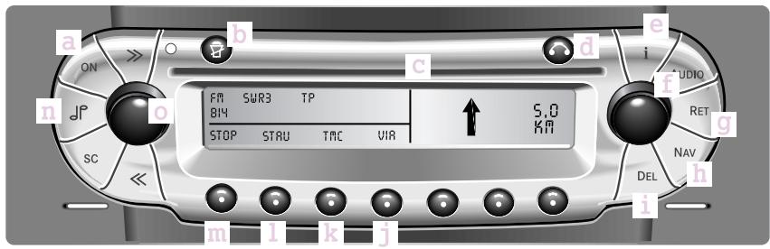
Navigation control elements
a Switching device on or off
b Interrupt navigation information or switch off
c CD tray
d CD eject button
e Information button
f Menu select and confirmation of selec-tion
g Back to previous menu
h Selecting navigation mode
i Delete an entry or a stored destination
j VIA function
k TMC function
1 Traffic congestion
m Intermediate stop
nSelection:Bass,treble,fader,balance
Volume control and playback of current navigation information
smart CD changer*
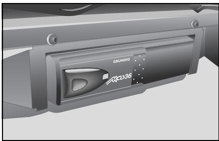
smart CD changer*
The smart CD changer is located underneath the passenger seat.
>Note!
More detailed information on the CD changer functions can be found in the operating instructions for the smart CD changer.
CD box\*
The CD box is located between the driver and passenger footwells in the vertical console.
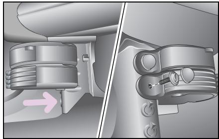
Installing and removing
In left-hand drive model
Push the CD box on the cone on the vertical console until the back of the CD box comes to rest against the vertical console.
Screw the housing of the CD box hand-tight with the aid of a coin.
- Check that the housing is located securely and fit the cover cap.
>Note!
Removal is done in the reverse order.
CD box*
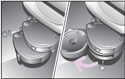
In right-hand drive model
Guide the CD box up against the fixing holes on the vertical console.
The housing of the CD box must rest against the vertical console.
Screw the housing to the left-hand fixing hole with the aid of a coin.
- Fold the CD trays open and secure the CD box through the hole in the rear wall with the second screw.
Check that the housing is located securely and fit the cover cap over the left-hand screw.
>Note!
Removal is done in the reverse order.
Installation in conjunction with the ashtray, the drinks holder* or the cassette box*
If so, note that the ashtray always must remain installed in the uppermost position and the drinks holder always installed in the lowest position. Always install the items in the vertical console from top to bottom.
The individual elements are linked together by guides.
Push the top side of the element to be installed as far as it will go along the guide on the underside of the element already installed above it.
Before screwing the individual elements tight, check that they are properly interconnected and are located flush one above the other.
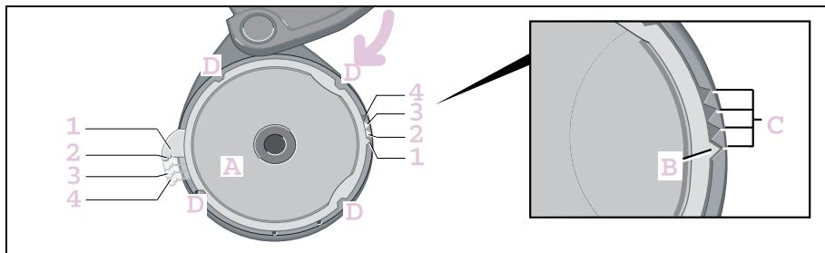
Changing the pull-out points of the CD trays
In order to find the desired CD tray more easily, you can place the pull-out points of the four CD trays at different positions.
- Swivel the frame with the CD tray out of the housing past the snap-in position until it stops.
Press the CD tray (A) upwards out of the frame.
Move the position arrow (B) of the CD tray to one of the recesses (C) of the frame.
There are four possibilities (1 - 4) for fitting the CD tray and positioning the pull-out points.
Press the CD tray and the frame together so that the four clips (D) interlock.
The frame with the CD tray can be swivelled back.
Repeat this process to position the pull-out points of the other CD trays to the desired positions.
Cassette box*
Cassette box*
The cassette box is located between the driver and passenger footwells in the vertical console.
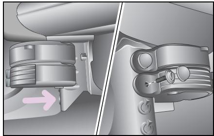
Installing and removing
In left-hand drive model
Push the cassette box on the cone on the vertical console until the back of the cassette box comes to rest against the vertical console.
Screw the housing of the cassette box hand-tight with the aid of a coin.
Check that the housing is located securely and fit the cover cap.
>Note!
Removal is done in the reverse order.
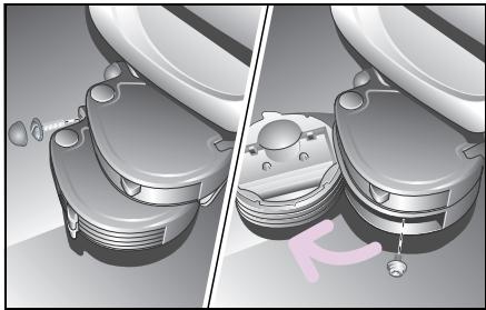
In right-hand drive model
Guide the cassette box up against the fixing holes on the vertical console.
The housing of the cassette box must rest against the vertical console.
Screw the housing to the left-hand fixing hole with the aid of a coin.
- Fold the cassette trays open and secure the cassette box through the hole in the rear wall with the second screw.
Check that the housing is located securely and fit the cover cap over the left-hand screw.
>Note!
Removal is done in the reverse order.
Installation in conjunction with the drinks holder or the CD box
If so, note that the ashtray always must remain installed in the uppermost position and the drinks holder always installed in the lowest position.
Always install the items in the vertical console from top to bottom.
The individual elements are linked together by guides.
Push the top side of the element to be installed as far as it will go along the guide on the underside of the element already installed above it.
Before screwing the individual elements tight, check that they are properly interconnected and are located flush one above the other.
Cassette box*
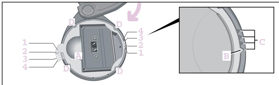
Changing the pull-out points of the cassette trays
In order to find the desired cassette tray more easily, you can place the pull-out points of the four cassette trays at different positions.
- Swivel the frame with the cassette tray out of the housing past the snap-in position until it stops.
Press the cassette tray (A) upwards out of the frame.
Move the position arrow (B) of the cassette tray to one of the recesses (C) of the frame.
There are four possibilities (1 - 4) for fitting the cassette tray and positioning the pull-out points.
Press the cassette tray and the frame together such that the four clips (D) interlock.
The frame with the cassette tray can be swivelled back.
Repeat this process to position the pull-out points of the other cassette trays to the desired positions.
Telephone console*
Accident risk! Mobile phones and two-way radio equipment that do not have a low reflection outside aerial may interfere with the vehicle electronics and thereby jeopardise the operational safety of the vehicle and your safety as well. Therefore, use this equipment only if it has been properly connected to a separate low reflection outside aerial.

Accident risk!
When operating mobile communications equipment in the vehicle, please observe the statutory requirements of the respective country. If operating communications equipment is legally approved while en route, be sure that you do so only when traffic allows. Otherwise you may fail to recognise hazards and could consequently cause an accident and injure yourself and others.
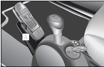
The telephone console provides for secure and convenient installation of your mobile phone. There are suitable cradles available for the various different makes of mobile phone. In order to use a different mobile phone in the universal hands-free system*, all you need to do is exchange the cradle.
The telephone console (A) is located in front of the gearshift lever.
Installing and removing
If you have a drinks holder in the car, remove this first (see operating instructions for drinks holder).
Telephone console*
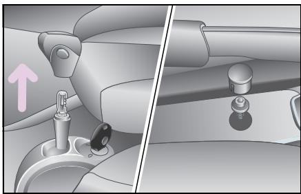
- Remove the cover cap on the centre tunnel console.
Release the Torx screw beneath it using a suitable screwdriver.
Pull up and remove the gearshift lever knob (on vehicles with softtouch*, take care not to press the automatic button when pulling it off!).
The centre tunnel console can be dismantled.
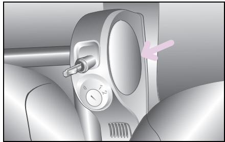
The centre tunnel console is fastened to the vehicle by means of two detent hooks at the front.
Bend open the console at the round inserts.
- Lift the centre tunnel console and remove it.
Place the centre tunnel console on a flat working surface.
Push the telephone console beneath the centre tunnel console until the undersides are parallel and the rounded section at the rear edge of the telephone console is parallel with the insert in the centre tunnel console.
Insert the enclosed screws through the designated holes, and screw them directly into the plastic of the centre tunnel console.
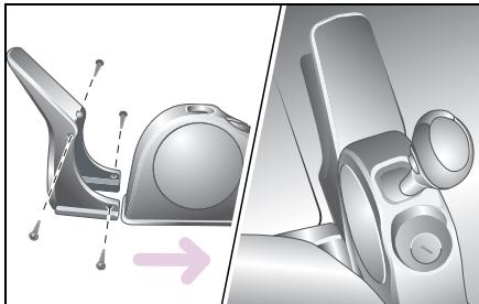
If you lay the leads to your cradle beneath the carpet for a neater appearance, you can run the leads between the telephone console and the centre tunnel console. You can use the recess on the telephone console for this.
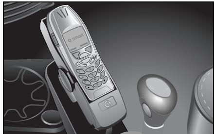
As long as the centre tunnel console is not fitted, you can lift up the carpet in this area to run the cable for the universal hands-free system beneath it. The location of the leads depends on the installation location of the universal hands-free system, and may vary.
Once the leads have been laid:
Bend the console open again at the front and push it down.
Fit the assembled consoles back over the gearshift bracket.
■ Ensure that the clips engage again.
Twist the screw back in.
■ Refit the cover cap.
Reattach the gearshift lever knob.
Mount the mobile phone cradle on the upper side of the telephone console.
>Note!
More information on operating and installing the cradles can be found in the respective operating instructions.
Universal hands-free system*
Universal hands-free system*
The universal hands-free system is connected up to the radio and loudspeaker system. The audio signals are thus reproduced via the car's loudspeakers, allowing the volume to be adjusted via the radio.
While you are using the phone
- the system is automatically activated,
- the word PHONE appears in the radio display,
- audio programs are automatically muted.
>Note!
More detailed information on the universal hands-free system is available in its operating instructions.
ipod*

Accident risk!
Keep focused on the events on the road. Do not use the Apple iPod en route. Doing so could distract you from traffic and cause an accident.
For safety reasons, only operate the system when the vehicle is stopped and if traffic conditions permit.
As a driver, you assume full responsibility for road safety.
Please note that when driving at only 50 km/h, your car will cover 14 metres every second!
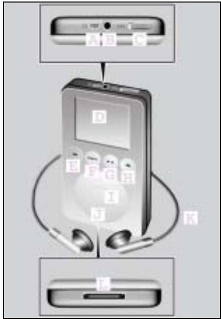
Controls
A Connection socket for the remote control
B Connection socket for headphones
C Hold switch
D Display
E Reverse button
F Menu button
GPlayback/pause button
H Forward button
I Selection button
J Scroll pad
K Headphones
L Dock connector connection
smart sound package*
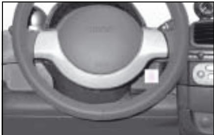
smart sound package*
In order to get the most out of your audio/ telematics equipment, the smart sound package includes additional speakers for power sound at hi-fi level.
You can connect mobile audio devices such as an MP3 player via the AUX jack1
(A) using a commercially available
3.5 mm jack plug.
The AUX jack is found in the stowage compartment between the steering column and the upper centre console2.
1 Does not apply to CD changer*
2 For left-hand drive models only
Contents
Sunvisors 90
Sunroof visor* 92
Power glass sliding roof* 93
Coat hooks. 95
Heater/ventilation. 96
Air conditioning plus* 102
Wipers 105
Rear window heater. 107
Outside mirror heaters* 108
Seat heater* 109
Car cover* 110
>>Weather outlook.
You can adjust to the weather by changing your clothes to suit. Similarly, your car offers a range of luxurious solutions such as, for example CFC-free air conditioning plus or an electric heater booster for diesels.
Sun visors
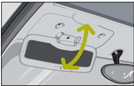
Sun visors
Protection against light from the front
- Swivel the sun visor downwards.
- Swivel the sun visor back up when the sun is no longer blinding you and you don't need it any more.
>Note!
The sun visors cannot be swivelled towards the side windows.
Mirror for the driver sun visor*

Accident risk!
Keep the mirrors in the sun visors covered while driving. Dazzling light could otherwise endanger yourself and others.
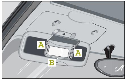
Fitting the mirror
The mirror for the driver sun visor is glued into place.
Clean the area of the driver sun visor to which it is to be affixed (A) with ordinary washing-up liquid or glass cleaner.
>Note!
Do not use alcohol or acetone. This could cause damage to the surface of the driver sun visor.
Do not touch the mounting area with the fingers, as this could impair the adhesive bond.
Dry the prepared area with a clean paper towel.
Remove the protective film from the two adhesive sections on the back of the mirror.
Insert the mirror for the driver sun visor into the fitting aperture (B) on the sun visor and secure with the locating pin.
Open the mirror cover.
Press both adhesive sections (A) on the back of the mirror firmly against the sun visor for about 20 seconds.
>Note!
The adhesive will take approx. 3 hours to harden completely.
Sunroof visor*
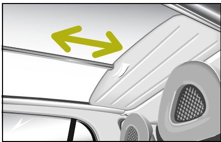
Sunroof visor*
The sunroof visor serves to protect against solar radiation and the build-up of heat through the glass roof.
Its easy-to-use operation allows you to slide the sunroof back and forth using one hand only.
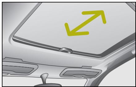
Wind and sunroof visor* for power glass sliding roof
This is only available together with the power glass sliding roof.
Power glass sliding roof*
Power glass sliding roof*

Danger of injury!
The glass sliding roof has an obstruction sensor feature. When closing it, nevertheless make sure that no one is trapped.

Switch for the power glass sliding roof
Opening and closing of the glass sliding roof is controlled via a rocker switch. It is located on the right, next to the gearshift lever. This enables the glass sliding roof to be opened to any desired position.
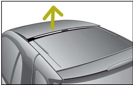
Raising the glass sliding roof
Press the rocker switch (when glass sliding roof closed) briefly to position A.
Power glass sliding roof*
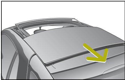
Opening the glass sliding roof
Closing the glass sliding roof
Press the rocker switch to position A and hold it there.
Press the rocker switch to position B and hold it there until the roof is completely closed.
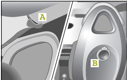
Coat hooks
Hang your jacket up on one of the coat hooks provided
- at the rear roof rail (A) or
- on the back of the seats (B).
Heater/ventilation
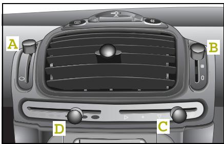
Heater/ventilation
Your heater and ventilation controls
- Fresh air/recirculated air selector (A)
- Blower (B)
Air distribution (C)
Air temperature/heater/heater booster (D)
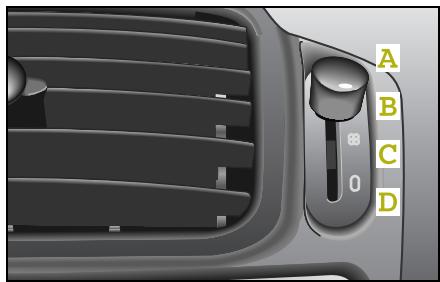
Switching the blower on
You can set the blower to four different levels:
- Blower on max./defrost (A) (for efficient defrosting and fast drying of the fogged windows)
- Blower middle setting (B)
- Blower slow setting (C)
Blower off (D)
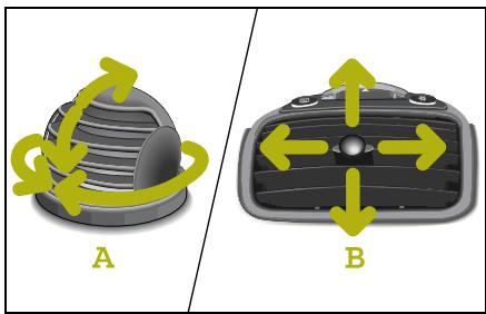
Adjusting the air nozzles
Rotary air nozzles
You can adjust the rotary air nozzle (A) by hand to suit.
Centre air nozzle
You can adjust the centre air nozzle (B) on the centre console by turning the adjusting knob to suit.
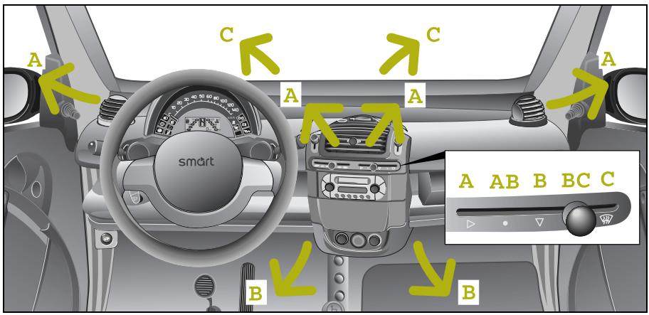
Air flow in the car
The air flows from the nozzles set to the respective blower stages as follows:
from the centre air nozzle and the rotary air nozzles (A),
- to the footwell (B),
- to the front and side windows (C).
Heater/ventilation
Your heater and ventilation controls

Accident risk!
Follow the settings recommended on the following pages for heating or cooling. The windows could otherwise mist up. This may prevent you from observing the traffic conditions, thereby causing an accident.
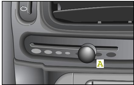
Adjusting the temperature
The further you push the knob (A) to the right-hand side, the warmer the flow of air will be.
Auxiliary heater*
The auxiliary heater heats or ventilates the interior to the temperature that you previously set using the temperature control switch.
Please refer to the separate operating instructions for detailed information on operating the auxiliary heater.
Electric heater booster\*1
If you wish to have the maximum heating effect:
- Slide button (A) as far right as it will go.
The electric heater booster is activated.
The indicator light in the instrument cluster for the electric heater booster comes on.
>Note!
The vehicle will consume more fuel as long as the electric heater booster is in operation.
To switch off the electric heater booster:
- Slide button (A) to the left.
The indicator light for the electric heater booster goes out.
Heater/ventilation
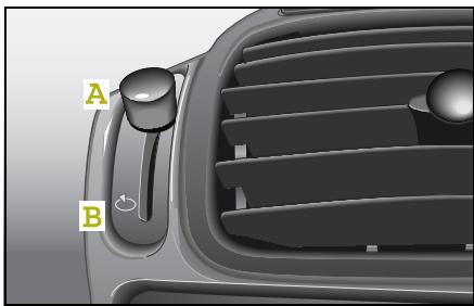

Accident risk!
Only switch over to air recirculation mode briefly for low outside temperatures. Otherwise, the windows could mist up, thus impairing visibility and endangering yourself and others. This may prevent you from observing the traffic conditions, thereby causing an accident.
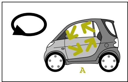
How to adjust the recirculated air or fresh air flow
Select the upper position for recirculated air (A).
The air circulates - e.g. when driving through a tunnel - in the passenger compartment.
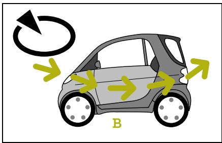
- Select the lower position for fresh air (B).
The air is drawn in from outside the car.
Heater/ventilation
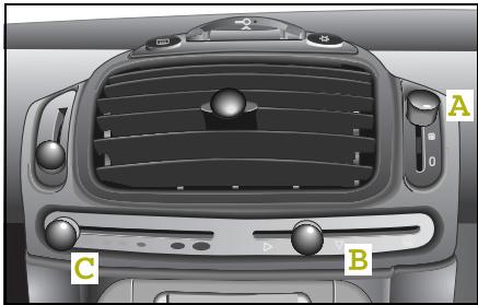
Rapid cooling
Set the
- blower (A) to maximum.
- air distribution (B) to the centre air nozzle, rotary air nozzle and footwell.
- heater (C) to the off position.
- direction of the air nozzles and rotary air nozzles if required.
- ventilation to recirculated air mode.
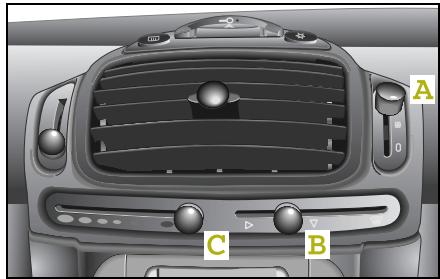
Rapid heating
Set the
- blower (A) to maximum.
Air distribution (B) to the centre air nozzle, rotary air nozzle and footwell.
- heater (C) to maximum.
The electric heater booster1 is switched on.
The heater booster indicator light 1 comes on.
- Direct the air nozzles towards the occupants.
De-icing the windows

Accident risk!
Never drive with iced-over or fogged windows. Visibility will be significantly impaired and can endanger yourself and others. This may prevent you from observing the traffic conditions, thereby causing an accident.

Environment!
De-ice and dry fogged windows before starting the engine.
Allowing the engine to idle when the car is at a standstill can damage the engine and pollute the environment.
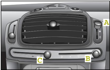
The most effective way to de-ice the windows is
- to remove the ice completely from the windows manually with an ice scraper before starting the engine,
- to turn the blower (A) to de-ice.
- to set the air distribution (B) to the front and side windows,
- to turn the heater (C) to maximum.
>Important!
Do not use an ice scraper to clear the side windows at the rear of the car from ice. This could cause damage to the surface of the windows.
Air conditioning plus*
Air conditioning plus*

Accident risk!
Ensure that you observe the recommended air conditioning system plus* settings described on the next few pages. The windows could otherwise mist up. This may prevent you from observing the traffic conditions, thereby causing an accident.
The air conditioning plus system improves the level of comfort when driving at high outside temperatures
- by cooling down the air,
- by dehumidifying the air.
Your heater and ventilation support the functions of the air conditioning plus system. Their operation is explained starting on page 96.
In addition, an integrated combination filter* (dust, pollen and particulate filter) purifies the fresh air inflow. It continues to operate when the air conditioning plus system is switched off and you have switched the blower on.
>Note!
Operating the air conditioning plus system increases fuel consumption.
>Note!
Dehumidification of the air by air conditioning plus system prevents the windows from fogging when there is a high level of moisture in the air.
This effect can also be used to de-ice the windows if, in addition to the air conditioning plus system, the heater is switched to maximum.
When will the air conditioning plus system operate?
The air conditioning plus system works
- only when the engine is running,
- only when the blower is switched on,
- most effectively when the windows are closed.
Air conditioning plus*
Outside temperature display*

Accident risk!
Even if the temperature is slightly above freezing, there could still be ice on the road, particularly in wooded areas and on bridges. The vehicle could skid if you fail to adapt your driving style. You should therefore always adapt your driving style and speed to suit the weather conditions.

Environment!
Keep the windows closed when operating the air conditioning plus system. This will save fuel.
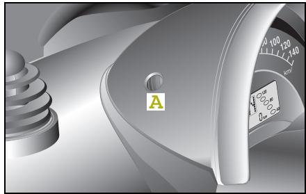
Press the selector knob (A) several times until the outside temperature display is activated.
Please observe the following notes before switching on the air conditioning plus system:
The car's interior will cool down faster if you do the following:
- Discharge the warm air. To do this,
- open a window briefly,
- turn the blower to its maximum setting, and
- close the window once the warm air has been discharged.
- Switch on the air conditioning plus system in recirculated air mode.
- Switch to fresh air mode after briefly operating the system in recirculated air mode.

Accident risk!
Only switch over to air recirculation mode briefly for low outside temperatures. Otherwise, the windows could mist up, thus impairing visibility and endangering yourself and others. This may prevent you from observing the traffic conditions, thereby causing an accident.
Air conditioning plus*
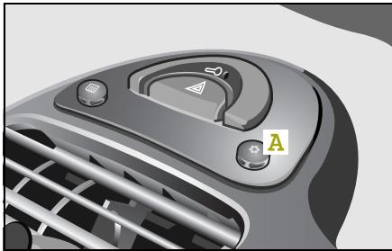
Switching the air conditioning plus* system on/off
The air conditioning plus system has three selector stages.
In each case press button (A) once in order to switch between the three stages.
1. Off
None of the indicator lights on the switch is illuminated.
2. Partial cooling
One of the indicator lights on the switch is illuminated.
3. Full cooling capacity
Both indicator lights on the switch are on.
>Note!
If the ignition or the blower is switched on again, the stored status (stages 1 - 3) will be reset.
The air conditioning plus system switches off automatically
- when the engine speed is too low,
- when driving off,
- when the blower is switched off,
- at a coolant temperature of more than 115^ C ,
- at outside temperatures below 5^ .
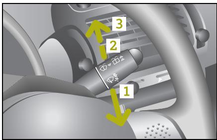
Wipers
The wiper lever is located to the right of the steering wheel.
The following wipe and wash functions are provided.
1 - Interval wiping, front
Delay duration of approx. 7 seconds while on the move.
Delay duration of approx. 11 seconds when vehicle at standstill.
2 - Windscreen wipers, slow
3 - Windscreen wipers, fast
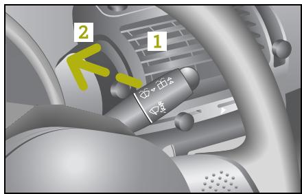
Rear window wiper1 and windscreen washer system
1 - Rear window interval wiping
Delay duration of approx. 10 seconds.
2 - Window washer system for rear window on
The windscreen washer system remains active as long as the wiper lever is pressed.
The wiper then proceeds to wipe for
3 more wipe cycles.
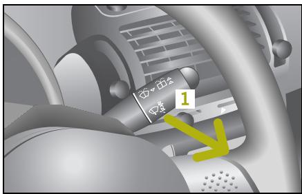
Windscreen wipers and windscreen washer system
1 - Window washer system for windscreen on
The windscreen washer system remains active as long as the wiper lever is pulled.
The wipers then proceed to wipe for 3 more wipe cycles.
>Note!
A short pull on the lever causes a single wipe to be conducted (touch contact wipe).
Wipers
Automatic wiper control*
The interval time for the windscreen wipers is controlled according to the car's speed.
The interval times for various travel speeds is as follows:
| Speed-sensitive interval times | 11 seconds | 7 seconds | 5 seconds | 3 seconds |
| For an increase in vehicle speed | 0-20 km/h | 20-75 km/h | 75-120 km/h | Above 120 km/h |
|
| Speed-sensitive interval times | 3 seconds | 5 seconds | 7 seconds | 11 seconds |
| For a decrease in vehicle speed | Above 110 km/h | 110-65 km/h | 65-10 km/h | 100 km/h |
The rear window wiper1 is automatically activated when the windscreen wipers are turned on and the reverse gear is engaged.
| Rear window wiper interval times | 12 seconds | 12 seconds | 6 seconds |
| According to position of windscreen wipers | Interval | Stage 1 | Stage 2 |
1 Only for the smart fortwo coupé.
Rear window heater
Rear window heater1

Accident risk!
Clear all windows of ice or snow before setting off. Impaired visibility could otherwise endanger yourself and others.
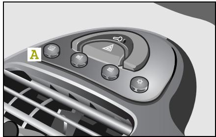
The rear window heater
- serves to free the rear window of ice quickly,
- clears the window if it has been fogged.
Switching the rear window heater on/off
Switch on the ignition.
You can help to prolong the life of the battery by switching the rear window heater on only when the engine is running.
Press the rear window heater switch (A) once.
The rear window heater is switched on.
The integrated indicator light comes on.
Press switch (A) again.
The rear window heater is switched off.
The integrated indicator light no longer illuminates.
>Note!
The rear window heater will switch itself off automatically after 10 minutes.
Outside mirror heaters*
Outside mirror heaters*
If your car is equipped with electrically adjustable outside mirrors, they will likewise be heated.
The outside mirror heaters
- serve to automatically de-ice the outside mirrors,
- give you a clear view when the outside mirrors are fogged.
Switching on outside mirror heaters
Switch on the ignition.
Switch on the rear window heater.
The outside mirror heaters automatically come on at the same time.
Switching off outside mirror heaters
Switch off the rear window heater.
The outside mirror heaters automatically switch off as well.
>Note!
In the smart fortwo cabrio, the outside mirror heaters are switched on and off with the ignition.
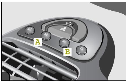
Seat heater*
The seat heater allows you to electrically heat the driver seat (A) and the passenger seat (B) when the ignition is switched on.
Switching the seat heater on/off
Three stages are provided for the seat heater.
1. Off
None of the indicator lights on the switch is illuminated.
2. Continuous operation
One of the indicator lights on the switch is illuminated.
3. Rapid heating of the seats at winter temperatures
Two indicator lights on the switch are illuminated.
>Note!
When the ignition is switched off, the seat heater is also switched off.
Malfunction
In the event of a seat heater malfunction, the indicator light on the switch lights up briefly and goes out again after the button is released.
Take the car to a qualified specialist workshop, e.g. a smart center.
Car cover*
Car cover*
Do not use the car cover to conceal extremely dirty vehicles, as the dirt particles will act like sandpaper on the paintwork.
>Important!
If the vehicle is to be continually covered up for longer than a month, the roof, engine compartment and luggage compartment areas must be ventilated at those areas where the car cover makes contact with a large surface. The vehicle's paintwork may absorb moisture, which has to be released. If the absorbed moisture is not released again, blotches may form on the paintwork. In order to prevent such stains from forming, spacers - made, e.g. from expanded polystyrene - should be inserted between the car cover and the vehicle surface to ensure that sufficient air can circulate.
Fitting the car cover
The car cover has been folded ex works so that when it is unrolled, the material's foam-based side always faces the bodywork.
Roll the car cover over the vehicle roof from the rear to the front.
■ Unfold the car cover on both sides.
Pull the cord tight so that the cover has a taut fit.
Removing the car cover
Slacken the cord.
- Fold the sides up onto the vehicle roof.
Roll the car cover over the vehicle roof from the front to the rear.
Contents
Soft top system
(onlysmartcabrio) 112
Windblocker*
120
Notes on the
soft top system . . . 122
Soft top system faults
m faults 123
Care notes and maintenance.... 125
>>Variable driving enjoyment.
Your smart for two cabrio has been designed such that it has both a sunroof top function and a rear soft top which can be lowered by means of only a few simple steps and removal of the side rails to give you a complete convertible.
Soft top system (only smart cabrio)
Soft top system (only smart cabrio)
The soft top system of the smart cabrio consists of a:
Sunroof top
- Rear soft top
- Side rails
You can remove the side rails over the doors when you open the soft top and fold down the rear soft top.

Danger of injury!
Ensure that no one is trapped or
injured when opening and closing the sunroof top or rear soft top.
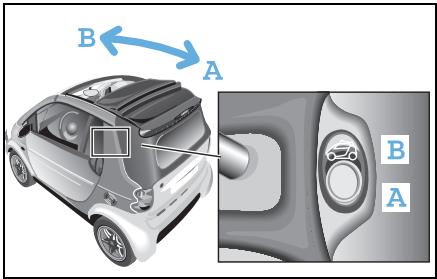
Opening the sunroof top
From the inside
Switch on the ignition.
Press down the rocker switch (A) until the sunroof top is fully open.
or
Briefly press down the rocker switch (A).
The sunroof top opens the full length.
>Note!
Pressing (A) or (B) during the opening process will stop the sunroof top in its current position.
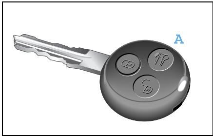
From the outside
The remote control allows you to fully open the sunroof top and unlock the rear soft top.
Press the button (A) on the remote control for approximately two seconds.
The sunroof top opens the full length.
Soft top system (only smart cabrio)
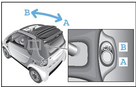
Closing the sunroof top
For safety reasons, the sunroof top can only be closed using the switch on the inside of the vehicle.
Switch on the ignition.
Press down the rocker switch (B) until the sunroof top is fully closed.
>Note!
The battery is drained when opening and closing the sunroof top. It is better to leave the engine running while opening and closing it.
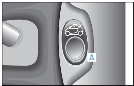
Opening the rear soft top
>Note!
Only perform this function with the car at a standstill!
Park the car.
■ Firmly apply the handbrake.
Leave the engine running or switch on the ignition.
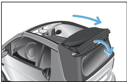
Fully open the sunroof top.
Press the rocker switch (A) for approximately 2 seconds or press the unlocking button on the remote control.
The rear soft top unlocks and falls down.
Soft top system (only smart cabrio)
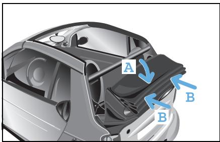
Press the rear soft top gently down by hand at the centre of the roof (A).
Ensure that the rear soft top engages on both sides (B).
>Important!
When the soft top is folded down, there is a risk of the side rails being stolen.
Therefore, it is better to remove the side rails and store them in the luggage compartment.
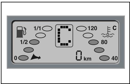
Warning message in display
If your car will not start and a C appears in the display, the rear soft top is not properly engaged. Please check the operating steps. Check, in particular, that the rear soft top has been properly locked into place.
Soft top system (only smart cabrio)
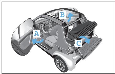
Removing the side rails
- Open the driver (A) and passenger (B) doors. Pay attention to traffic while doing so.
Open the tailgate (C).
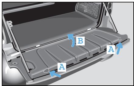
Press both release buttons (A) on the inside of the tailgate.
- Fold the cover (B) of the storage space upwards.
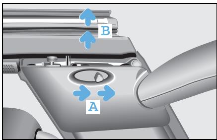
- Slide back the release lever (A) for the side rail.
The side rail can be lifted in the back (B), however remains secured.
Slide back the release lever (A) again.

Danger of accident injury!
For safety reasons, only unlock the soft top when the vehicle is at a standstill. Otherwise you could lose control of the vehicle and injure yourself and others.
Soft top system (only smart cabrio)
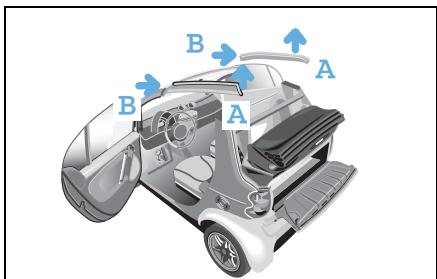
- First lift the side rail at the rear side (A) and pull it out in the direction of the arrow (B). Pay attention to traffic while doing so.
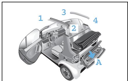
- Open the velcro straps on the storage space.
- Insert the side rails into the storage space of the tailgate (A) as numbered in the illustration, with the guide lug to the left and the painted side facing to the bottom.
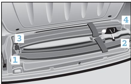
Danger of injury! Always properly fasten the velcro straps when stowing the side rails. Occupants otherwise could be injured by the side rails in an accident, during braking manoeuvres or abrupt changes in direction.
- Secure the side rails with the velcro straps.
- Close the storage space cover.
Soft top system (only smart cabrio)
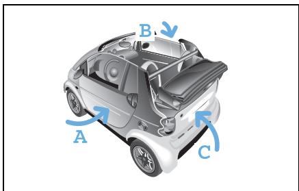
- Close the driver (A) and passenger (B) doors.
- Close the tailgate (C).
- Open the side windows as needed.
>Note!
Ensure that the storage space cover is closed before closing the tailgate. Otherwise the tailgate could jam.
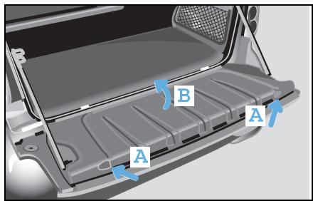
Closing the rear soft top
Mounting the side rails
- Open the driver and passenger doors.
Opening the tailgate.
Press both release buttons (A) on the inside of the tailgate.
- Fold the cover (B) of the storage space upwards.

- Open the velcro straps on the storage space.
Remove the side rails from the storage space in the tailgate.
Soft top system (only smart cabrio)
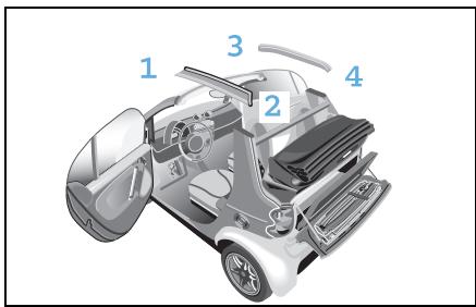
>Important!
The side rails are installed according to the numbering scheme in the illustration.

Danger of injury!
Ensure proper mounting of the
side rails. Otherwise the side rails could disengage en route and injure you and other persons.
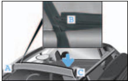
Take a side rail and insert the front section (A) first.
Ensure that the seal of the side rails is facing up at position (B) and is not pinched.
Press the side rail down at the rear section (C) until it audiably engages.
Install the side rail on the other side in the same fashion.
>Important!
Ensure that the side rails are properly installed, otherwise malfunctioning or damage can occur.
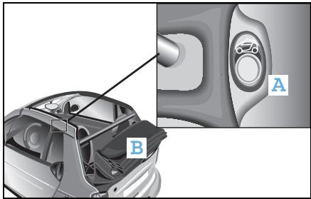
Closing the rear soft top
Close the tailgate.
Press the rocker switch (A) for approximately 2 seconds.
The rear soft top (B) unlocks in its lowered position.
Soft top system (only smart cabrio)
- Lift the rear soft top at the top until it comes to a stop in the intermediate position.
Using both hands, guide the rear soft top upwards in the vicinity of the centre brake light.
Lightly press the rear soft top until it catches.
>Important!
Ensure that the rear soft top is engaged on both sides. If the rear soft top is engaged only on one side, malfunctioning or damage can occur.
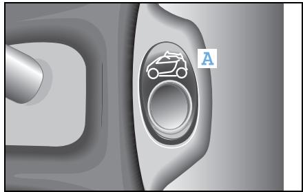
>Note!
When the rear soft top is properly engaged, you will hear a clicking sound. When the ignition is switched on, the rear soft top automatically locks.
Press down the rocker switch (A) until the sunroof top is closed.

Danger of injury!
Ensure that no one is trapped or injured when opening and closing the sunroof top.
Windblocker*
Windblocker*
You should be aware of the following:
- The screws, double panes and spanner are only required for first-time assembly.
- The windblocker should always be stowed in the original PE bag after use.
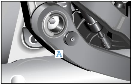
Mounting the windblocker
Screw the enclosed double panes to the pull rods (A) using the enclosed spanner. This mounting process needs to be carried out only once.
Gently tighten the screw (to a maximum torque of 0.7Nm ). There is a hole in the pull rods for this purpose.
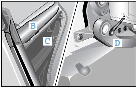
Take the windblocker and stand behind the vehicle with the soft top lowered.
There are small rectangular openings (B) on the roll bar's plastic shells.
On the windblocker you will find the corresponding securing flaps to fit into these openings (C).
Fix the windblocker in the plastic shells on both sides of the roll bar as shown in (C). The plastic flaps should face inwards.
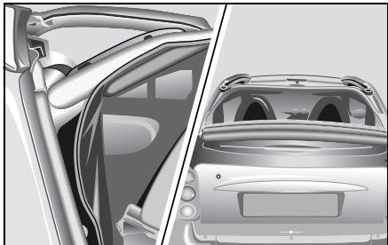
Reach between the soft top and the windblocker and fasten both round rubber cords in the double panes.
Dismantle in reverse order.
The screwed-on double panes remain in place.
>Note!
The soft top can be either open or closed when the windblocker is mounted.
Notes on the soft top system
Notes on the soft top system
To avoid causing damage to the sunroof top, rear soft top and soft top system, please observe the following notes:
Protecting the sunroof top
- When transporting long objects inside the car, make sure that they do not press against the sunroof top when it is closed.
- Do not allow the surface of the sunroof top to come into contact with lyes or acids.
Protecting the rear soft top
- Do not sit on the folded down rear soft top.
- Do not place any evenly distributed loads with a weight of more than 75kg on the rear soft top when folded down.
- Do not fold down the rear soft top at temperatures below -10^ .
- When loading, make sure that no sharp objects come into contact with the soft top or the rear window.
- Do not place any pointed, sharp-edged, hot (above 80^ ), incandescent or burning objects on the soft top's canvas.
- Do not allow the surface of the soft top to come into contact with lyes or acids.
- Do not apply wax to the soft top fabric and select only wax-free washing programmes when using an automatic car wash.
- Do not use an ice scraper on the rear window.
Protecting the soft top system
- Do not block the soft top system's locking apertures.
- Only place the side rails in the designated storage space of the tailgate.
- Do not erect the retaining clips at temperatures below -10^ .
- When carrying objects that protrude from the rear of the car, make sure that they are not resting on the retaining clips.
Other notes
- Make sure that the third brake light is not concealed.
- Drive only with the retaining clip closed, as exhaust fumes could otherwise reach the car's interior.
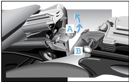
Soft top system faults
The rear soft top is engaged at one side only
When docking to the B-post, it is possible that the rear soft top could engage on one side only. This may occur if the predetent engaging catch has closed prematurely. If this occurs, proceed as follows:
Open the pre-detent engaging catch
■ Release the pre-detent engaging catch (A) with the emergency operation key from the pin (B) of the B-post lock on the side that is engaged.
On the pre-detent engaging catch, there is a triangle indicating the direction of opening.
■ Engage the rear soft top again in the lower storage position.
The pre-detent engaging catches are now moved automatically back into the home position.
Now dock the rear soft top as described in "Closing the rear soft top" (see page 117).
Soft top system faults
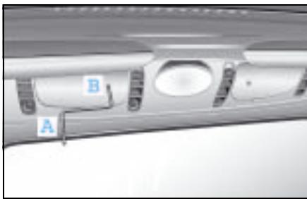
The sunroof top or rear soft top can no longer be operated electrically
If this occurs, proceed as follows:
Unlock the rear soft top from the lowered position
- Remove the emergency operation key (A) from the vehicle document wallet and insert the key into the opening (B) of the electric motor cover.
Move the key gently to and fro until it is felt to engage in the hexagonal socket opening of the electric motor.
Screw the emergency operation key in the clockwise direction up to the stop point.
A "clicking" noise signals that the pre-locking engaging catch has been released.
Remove the emergency operation key.
- Lift the rear soft top and engage it into both sides of the B-post.
>Note!
If the rear soft top cannot be docked, the electric motor was not turned to the stop point.
Closing the sunroof top
- Reinsert the emergency operation key into the hexagonal socket on the electric motor.
Turn the emergency operation key in the anticlockwise direction until the sunroof top is fully closed.
Ensure that the sunroof top does not tilt.
>Important!
When turning the emergency operation key, take care not to scratch the rear window.
Care notes and maintenance
Care notes and maintenance
Regular care will protect the sunroof top and the rear soft top of your vehicle against external influences, helping to preserve its value. Use only smartcare soft top cleaner when removing dirt from the soft top.
>Important!
- Please observe the instructions for use printed on the packaging of the cleaning agents.
- It is best to wash your vehicle by hand.
smart gmbh recommends the use of smart-care products, as
they exhibit excellent cleaning capability and provide an optimum level of protection,
- the products have been specifically designed with the smart's materials in mind and
- allsmartcare products are free of dyes and fragrances.
>Note!
Allsmartcareproductsareavailable fromasmartcenter.
The following types of dirt should be removed immediately:
Bird droppings
Tree resins
Dead insects
>Note!
Failure to remove such contamination immediately may result in damage to the soft top. These factors are environmental influences that are not covered by warranty.
Care notes and maintenance
Cleaning the sunroof top and the rear soft top
>Important!
- Avoid cleaning with a water pressure of more than 10 bar or with the water jet less than 30~cm (1 ft) away from the soft top fabric, seals, surfaces or joins.
- Do not clean the sunroof top or rear soft top with a high-pressure cleaner (pressure not to exceed 10 bar).
- Do not direct the water jet directly at the openings in the spoiler.
- Be sure to also observe the care notes (see page 219).
Cleaning the soft top fabric
>Important!
Perform cleaning only with the sunroof top and rear soft top closed.
Dry cleaning
Brush the soft top fabric with a soft brush, always working in the same direction from front to back.
Wet cleaning
Usesmartcareproductsforallwetcleaningtasks
- Car shampoo concentrate or
- Soft top cleaner
First dry brush the soft top.
Then wash the soft top fabric using ample lukewarm water.
Use a soft brush or a sponge while doing this.
Thoroughly rinse the car with clear water afterwards.
Care notes and maintenance
Cleaning and polishing the rear window
Clean the rear window using lukewarm water and smartcare car shampoo concentrate or glass cleaner.
>Note!
Use a clean, soft sponge or clean, soft cloths in order to ensure that the rear window is not scratched.
>Note!
In the event that the rear window's transparency deteriorates, it can be polished using a special smartcare plastic polish. Please observe the application instructions on the polish packaging.
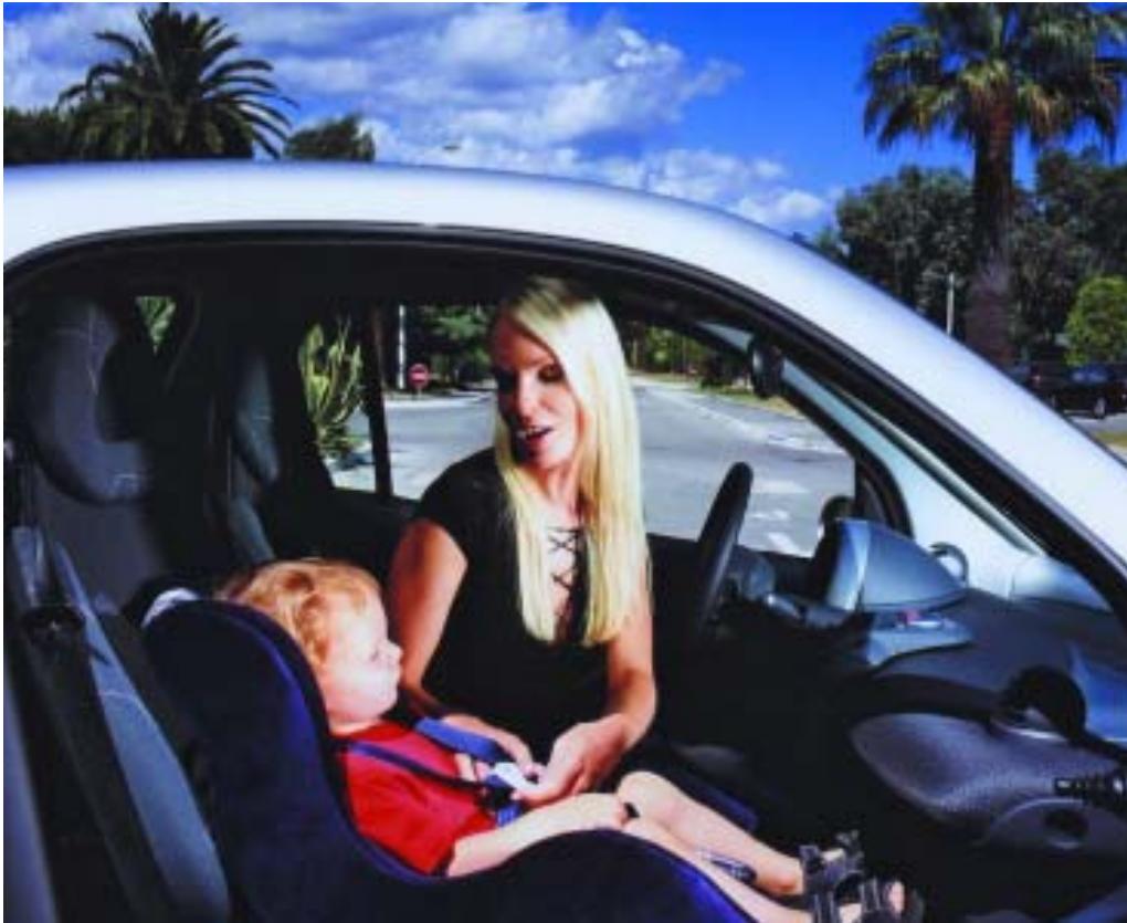
Contents
Child restraint systems* 130
Using child restraint systems*.133
>>Child friendly.
The safety of your children is a matter close to our heart.
For this reason, we have developed a child restraint system which fulfils the most stringent safety criteria. To make sure that your children are comfortable, the system has been designed using the latest ergonomic findings.
Child restraint systems*
Child restraint systems*
Without suitable child restraint systems
- the seat belts cannot be fastened correctly.
- your children will be exposed to a greater risk of injury, as children's muscles and bones are not yet fully developed.
To reduce this increased risk of injury, children need suitable child restraint systems if they are
- smaller than 150 cm or
- under 12 years of age.
smart gmbh recommends that you use the child restraint systems listed on page 134. Details of these products are provided in the operating instructions for the individual items. Please read them carefully.
>Note!
Observe the respective national regulations in this regard.
Child restraint systems*
What you must note when transporting children!

Risk of accident and injury!
Do not leave children unsupervised in the vehicle. They could open the doors, release the parking brake or injure themselves on moving parts, thus endangering themselves and others. Please also observe the warnings given elsewhere in these operating instructions regarding children and the vehicle.

Danger of injury!
It will not be possible to fit the seat belts correctly on children under 150 centimetres tall or under 12 years of age without suitable support equipment. They therefore need special child restraint systems for protection in the event of an accident. never allow children to travel sitting on the lap of another occupant. They can no longer be secured due to the forces occurring in the event of an accident, heavy braking or sudden change in direction. They may be thrown against parts of the vehicle interior and be seriously or fatally injured When fitting a child restraint system, observe the manufacturer's fitting instructions.
-
On child restraint systems that do not have their own belt system, the shoulder belt of the car's built-in three-point seat belt must run approximately across the middle of the child's shoulder - never across the neck - and lie firmly against the upper body. The lap section of the seat belt must run across the pelvis - not across the stomach - and always lie firmly in place. Tighten the belt if necessary.
-
Only one child at a time should be secured by any child restraint system.
- Make sure that the belt is not trapped, twisted or rubbing against sharp edges.
Also observe the operating instructions for the child restraint system.

Danger of injury!
To reduce the risk of serious or fatal injury to the child in the event of an accident, braking or sudden change in direction:
Child restraint systems*

Danger of injury!
If the child restraint system or its fastenings have previously been damaged or subjected to loads in an accident, the child it is intended to protect could sustain serious or even fatal injuries as a result of another accident, braking manoeuvres or abrupt changes of direction.
You should therefore have restraint systems and fastenings that have been damaged or subjected to loads in an accident checked without delay in a qualified specialist workshop, such as a smart center, and have them replaced if necessary.

Danger of injury!
If the airbag indicator light does not come on when a baby carrier is fitted to the passenger seat, the passenger airbag has not been deactivated. If the passenger airbag has not been deactivated, a child could sustain serious or even fatal injuries in the event of the airbag on the passenger side being triggered, particularly if the child is in the immediate vicinity of the passenger airbag at the time of its activation.
The passenger airbag is only deactivated when you fit a special smart baby carrier to the passenger seat.

Danger of injury!
For this reason, you should never carry a child on the passenger seat in a child restraint system that faces to the rear if the passenger airbag has not been deactivated, i.e. if the airbag indicator light is not lit.
Also observe the corresponding warning sticker on the instrument panel. If you have installed an original smart baby carrier on the passenger seat and the airbag indicator light does not come on (restraint system not identified), have the automatic restraint system recognition function checked without delay by a qualified specialist workshop, such as a smart center. Until this problem has been rectified, do not carry children in the car, as they could sustain serious or even fatal injuries in the event of an accident.
Using child restraint systems*
Using child restraint systems*
The table below provides you with an overview of the installation options for child restraint systems in your car.
| Seats | Weight categories and approximate age groups |
| up to 10 kg
(up to approx.
9 months) | up to 13 kg
(0 to 2 years) | 9 to 18 kg
(from approx. 9 months to
4 years) | 15 to 36 kg
(from approx. 4 months to
12 years) |
| Passenger seat | - | B | UV | UV |
| UV:Suitable for front facing "universal" child restraint systems that have been approved for this age group.
B:Suitable for special child restraint systems included in the enclosed list. The child restraint systems in question may be "vehicle-specific", "restricted", or "semi-universal". |
Using child restraint systems*
Recommended child restraint systems
| Weight group | Manufacturer | Model | Homologation No. | smart article number | Comment |
| up to 10 kg (to 9 months) | - | - | - | - | |
| up to 13 kg (0 to 2 years) | Storchenmühle | Baby carrier* | E4 03 442811 | LU 0010322 | 1), 2) |
| Storchenmühle | Quick coupling* and Basisfix* Left-hand drive | Components Approval Baby carrier | LU 10327 V002 | 1), 2) |
| Storchenmühle | Quick coupling* and Basisfix* Right-hand drive | Components Approval Baby carrier | LU 10328 V002 | 1), 2) |
| 9 to 36 kg (from 9 months to 12 years) | Storchenmühle | Child restraint system Air seat* Right-hand drive mod- el/left-hand drive mod- el | E1 03 301085 | LU 15081 | 1) |
| 15 to 36 kg (from 4 to 12 years) | Klippan | Booster cushion* for children | E11 03 44066 | LU 0002617 | 1) |
| Klippan | Backrest* for booster cushion* | E11 03 44112 | LU 0004663 | 1) |
1) When these child restraint systems are used, the front passenger seat must be moved to the rearmost position.
2) Disabling of front passenger front airbag essential if baby carrier used on front passenger seat.
Contents
Before driving off. 136
Driving 139
Parking 147
Driving in winter. 149
Driving with a catalytic converter. 151
Driving tips 152
Cruise control* 154
Speed limiter* 157
Brakes. 160
Electronic Stability Program (esp) 165
Airbags 166
>>Study in motion.
When a study evolves into driving enjoyment, then we are dealing with a car that conveys an entirely new driving experience. A gearshift control similar to what we see in the Formula 1 or sports cars. You can shift the soft tip sequential 6-speed gearbox without using the clutch. And when in softtouch* automatic mode, your vehicle shifts all by itself. Additionally, esp helps you to get through the winter safely and also counteracts skidding!
Before driving off
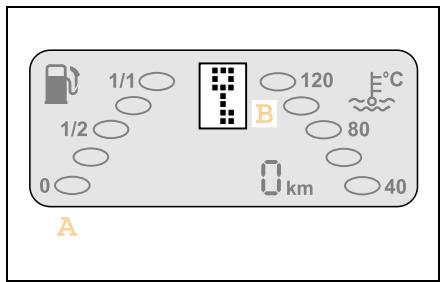
Before driving off
Acquaint yourself with the operating controls in your car before starting your first journey.
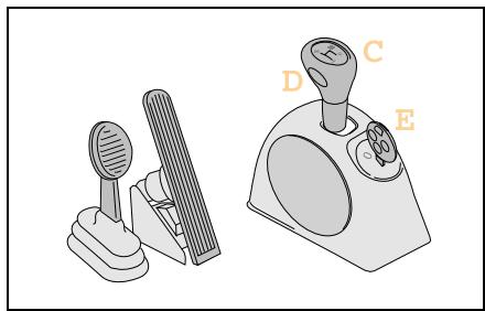
In particular, you should study its special technical features:
- (A) display with gear indicator
- (B) electronic immobiliser
- (C) gearshift lever
-(D) selector button for softmax/soft-ouch*
- (E) position of ignition switch
- no clutch pedal
Please study this chapter very carefully.
Get to know the car and how to handle it.

Accident risk!
Make sure that there is sufficient clearance around the pedals when floor mats* are used and that they are securely fastened. Do not keep any objects in the driver footwell.
Check that the floor mats are secured and correct them if necessary before beginning a journey. An insufficiently secured floor mat could slip and obstruct pedal actions.
Do not place floor mats on top of one another.

Accident risk!
Mobile phones and two-way radio equipment that do not have a low reflection outside aerial may interfere with the vehicle electronics and thereby jeopardise the operational safety of the vehicle and your safety as well. Therefore, use this equipment only if it has been properly connected to a separate low reflection outside aerial.
Before driving off
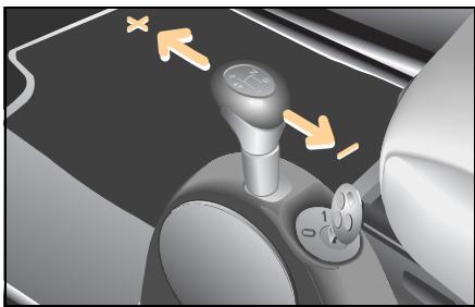
Gearshifts
You change gear in your car in various ways, depending on its specification:
Manual shifting (softip)
Shifting between gears (+ or -) is done by tipping the softtip selector out of the gearshift plane.
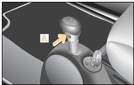
Automated shifting (softouch)*
Shifting between the gears occurs automatically when the gearshift lever is in the gearshift plane and you press button (A).
>Note!
When you start the car, manual shifting (softtip) is selected. Exception: Brabus vehicles.
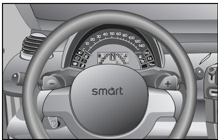
Gearshifts from the steering wheel*
The 3-spoke leather-wrapped sports steering wheel with shifting capability allows you to shift gears without taking your hands off of the wheel.
To change gear, briefly press the shift paddles on the steering wheel with the gearshift lever in the gearshift plane.
Driving
Breaking in
The first 1,500 km (approx. 930 miles) are of immense significance for the service life and performance of your car's engine.
During the break-in period:
- Do not drive at full throttle.
- Shift gears in good time, i.e. when the gear indicator tells you to do so.
- Avoid driving at high engine speeds.
When the break-in period is over:
You can gradually start to drive your car faster, progressing up to top speed and maximum engine speed.
>Note!
Please study the driving notes contained in these operating instructions.
Driving
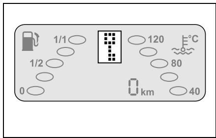
Electronic immobiliser
If the car remains unlocked for more than 5 minutes, the electronic immobiliser is automatically activated.
With electronic immobiliser activated
- the display shows when you turn the ignition key to position 1.
- a beeper sounds three times.
How to deactivate the electronic immobiliser:
Turn the ignition key back to position 0.
Press pushbutton on the ignition key. If you have an infrared remote control, you need to aim at the inside rearview mirror.
A single beeper tone indicates that the electronic immobiliser is deactivated.
Turn the ignition key back to position 1.
A 1, N or R is shown in the gear indicator.
Starting the engine

Danger of poisoning!
Never leave the engine running in enclosed spaces. The exhaust emissions contain poisonous carbon monoxide. Inhaling exhaust emissions is hazardous to your health and can cause loss of consciousness and even death.

Accident risk!
There is no servo assistance for the steering or brakes when the engine is not running.
Considerably more effort will be needed to steer and apply the brakes.
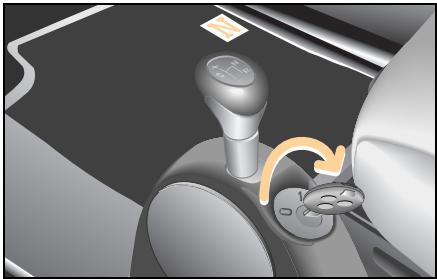
Starting the engine (petrol engine)
Fasten your seat belt.
Apply the footbrake.
Insert the key in the ignition switch.
Turn the key to 1.
Move the gearshift lever to position N.
An N appears in the gear indicator.
■ Briefly turn the key to the right.
The engine starts automatically (one-touch starting).
Starting the engine (diesel engine)
Fasten your seat belt.
Apply the footbrake.
Insert the key in the ignition switch.
Turn the key to 1.
Move the gearshift lever to position N.
An N appears in the gear indicator.
The preheat indicator light in the instrument cluster comes on.
- When the preglow indicator light goes out, you can start the engine.
■ Briefly turn the key to the right.
The engine starts automatically (one-touch starting).
Driving
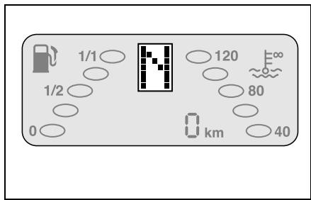
>Important!
The engine only starts when the gearshift lever is in position N
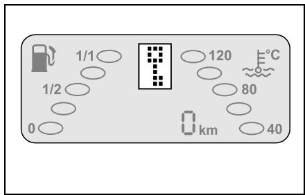
>Note!
If a is shown on the gear indicator, the electronic immobiliser must first be deactivated (see page 140).
If a is shown on the gear indicator, the soft top on the smart fortwo cabrio must be firmly locked into place.
>Note!
If, when starting, the electronic immobiliser is activated or the reverse gear is engaged, the light on the display will flash.
Engine will not start
Check once again whether
- the gearshift lever is in position N.
- the footbrake has been applied.
- the gear indicator is displaying an N .
- the electronic immobiliser is deactivated.
1. If the engine does not start within a period of 4 seconds:
Wait for a few moments.
Try to start the engine again.
2. Engine will not start:
- Secure your car against rolling away if you have to leave it.
- Call a breakdown recovery service such as smartmove Assistance or a qualified specialist workshop such as a smart center.
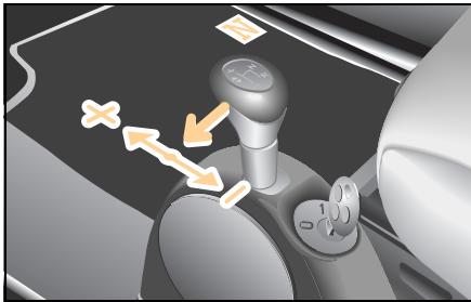
Driving off
Apply the footbrake.
Pull the gearshift lever out of position N to the left into the gearshift plane.
A 1 or A^* is shown on the gear indicator.
■ Release the footbrake.
Apply pressure to the accelerator pedal gradually.
The car will move off.
>Note!
If a 0 appears on the gear indicator, this indicates that a gear has not yet been engaged. The footbrake was not applied while moving the lever in the gearshift plane.
Driving off uphill
Your car has a hill-start assist system (ASS).
When driving off uphill, your vehicle is held in place for approximately one second after you release the footbrake.
As a result, you
- have enough time to move your foot from the brake pedal to the accelerator in order to accelerate.
- are able to prevent the car from rolling back; this protects the clutch.
Release the footbrake.
Apply sufficient pressure to the accelerator pedal.
The car will move off.
>Note!
The driving assistant is not activated if you start off with the handbrake applied.
>Important!
After approximately one second, the AAS stops braking the vehicle, which then can roll backwards. If you open the driver door within this time, AAS is deactivated and a warning signal sounds.
Driving

Reversing the car
Apply the footbrake.
Shift the gearshift lever out of position N and pull it back to position R.
An R appears in the gear indicator.
Release the footbrake.
Apply pressure to the accelerator pedal gradually.
The car will move off.
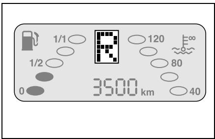
>Note!
Engage the reverse gear only when the car is at a standstill.
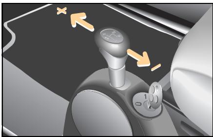
Manual shifting (softip)
To continue to accelerate the car, press the accelerator pedal.
The gear indicator displays the gear currently engaged.
An arrow will appear in the gear indicator display advising you to shift up (↑) or down (↓).
- Keep the pressure on the accelerator pedal.
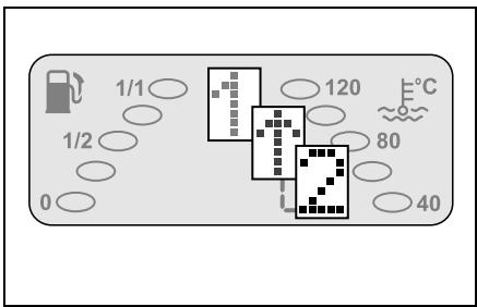
■ Briefly press the gearshift lever towards + to shift up or towards - to shift down.
The gearbox will shift to the next higher/next lower gear.
The gear indicator then shows the next highest/lowest gear selected.
>Notes on shifting!
- When coming to a stop, e.g. at traffic lights, the car will automatically select 1st gear.
- The car will automatically shift up a gear once you reach the engine speed limit.

Environment!
Upshift as soon as the gear indicator arrow prompts you to do so. This will save energy and help to protect the environment.
Driving
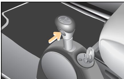
Automated shifting (softouch*)
In the gearshift plane, press the soft-ouch button.
The car will perform automated gearshifts.
An A appears in the gear indicator.
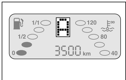
To return to softmax:
Press the gearshift lever in the direction + or - or press the softtouch button.
>Note!
When you start the car, manual shifting (softtip) is selected.
Exception: Brabus vehicles.
Kickdown*
Vehicles with softtouch or vehicles with cruise control:
Use the kick-down function when you want maximum acceleration.
Depress the accelerator past the pressure point.
The transmission downshifts.
Take your foot slightly off the accelerator once you have reached the desired speed.
If you press the accelerator beyond the kick-down point to make a sports start, the clutch is not engaged until the engine has reached a higher speed.
Parking

Accident risk!
When you stop the car on a hill or park it, it must be secured additionally by means of the handbrake.
The vehicle could otherwise set itself in motion - even with the gearshift lever in position R. This could result in an accident and cause serious or even fatal injuries.

Accident risk!
Do not park the car with the engine running and a gear engaged. This could allow the car to set itself in motion and cause an accident.

Danger of injury!
Never leave children unsupervised in the vehicle. They could e.g. release the handbrake This could result in an accident and cause serious or even fatal injuries.
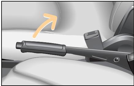
Park the car.
Apply the footbrake.
Apply the handbrake.
Switching off the engine
Move the gearshift lever to position R.
Wait until the display shows R.
Slowly release the footbrake.
Turn the key in the ignition switch to position 0.
Remove the ignition key.
Press the release button on the belt catch and let the belt run back by hand.
Parking
>Important!
In order to ensure that the turbocharger can quickly cool down after a full-load journey, the last few kilometres should be driven at a slow pace or the engine should run in neutral for a short period prior to switching off the engine.
>Note!
The reverse gear R is not a runaway protection device (parking lock), and if the car is parked on a hill with a steep incline it may still roll away.
The car is only ever 100 % safe when the handbrake has been applied.
Driving in winter
Driving in winter
At the beginning of winter, have your vehicle winterised by a qualified specialist workshop such as a smart center.

Accident risk!
Failure to observe the notes on gear shifting and driving in winter conditions may result in diminished operating stability, e.g. the rear end could break away. lead you to cause an accident.
Accident risk!
On bends, even electronic systems are only capable of providing a limited degree of stabilisation. Always adapt your driving style to the road, traffic and weather conditions. Reduce your speed before entering a bend. You could otherwise cause an accident.

Accident risk!
The risk of an accident especially increases when driving too fast, particularly when cornering and on wet or slippery roads as well as when driving too closely to the vehicle in front. Electronic control systems such as esp are unable to reduce this risk or override the laws of physics. You should therefore always adapt your driving style to suit the prevailing road and weather conditions and maintain a sufficient distance from other road users and objects on the road.
Driving in winter
A qualified specialist workshop such as a smart center will check
- the condition of your winter tyres,
- the condition of the engine oil,
- the concentration of anti-corrosion agent and antifreeze in the coolant,
- the mixture ratio in the washer system,
- the state of charge of your battery. Electronic systems (such as esp) are not able to overcome the laws of physics.
Adapt your driving style and speed to the winter road conditions and exercise caution when accelerating and braking.
Please pay particular attention to the following notes concerning winter driving:
- Use only wheels and tyres approved by smart gmbh.
- Change over to winter tyres at an early date, preferably in the autumn.
- Drive at low engine speeds.
- Avoid extreme load reversals.
- Upshift in good time (low-speed driving) and take your foot off the accelerator pedal when shifting gears.
- Avoid sudden, jerky movements of the steering wheel.
- Brake your car in good time before entering a bend.
Driving with a catalytic converter
Driving with a catalytic converter Things you need to know

Danger of injury and danger of burns!
The catalytic converter can get extremely hot. Coming into contact with it could result in burns. Note the following:
- Do not remove the protective heat guards.
- Do not apply any underseal.
-
When parking the car, make sure that the catalytic converter cannot come into contact with any flammable material (e.g. hay or grass). It could otherwise ignite and cause fire damage or injury.
-
The catalytic converter reduces exhaust emissions.
- The catalytic converter is located at the rear of the car.
- Fill up with lead-free petrol only. Even small quantities of leaded petrol can damage the catalytic converter.
It is essential to heed the following points, as there is otherwise a danger of overheating and the catalytic converter may be damaged.
- Make sure you adhere to the prescribed service intervals.
- Never run the fuel tank empty.
- If the engine starts to misfire, bring the car to an immediate standstill without endangering traffic.
- If the engine fails to start the first time, you should not try to start it any more than three times in succession.
- Do not run the starter motor for periods of more than 4 seconds at a time.
Driving tips
Driving tips
The following tricks will help you to save a substantial amount of fuel with your car.
Not only will you reduce your operating costs; you also will be helping to protect the environment.
1. Take five
The following holds true for traffic lights, rail barriers and when sitting in tailbacks: always switch the engine off, as you only need to be stopped for 10 seconds to save money.
>Important!
Make sure when you are about to drive off again that
- the selector lever is set to position N ,
- the footbrake is applied,
- the gear indicator is displaying an N .
2. Full speed ahead
Driving off expends considerably more energy than driving at a constant speed. So when starting off, drive for no more than two vehicle lengths (approx. 5 m) in 1st gear and accelerate briskly with the throttle at least three quarters of the way down.
3. Please shift
Shift gears in good time when the gear indicator in the display advises you to do so.
4. Keep on running, look ahead
Frequent braking followed by accelerating will cause your car to use up distinctly more fuel than otherwise. For this reason you should keep your distance from the vehicle in front and ease off the accelerator in good time whenever possible.
5. Letting go
It is always better to let the vehicle roll with the transmission in gear and to apply no gas than to roll in neutral. This way, fuel consumption is zero (deceleration fuel shutoff).
6. Under pressure
Correct tyre pressures help save fuel, increase tyre service life and improve braking safety. Tyre inflation pressures are given on the inside of the fuel tank flap for various load and climate conditions.
7. Shedding ballast
Mounted top carriers, bicycle carriers and ski boxes will increase air resistance and in turn the fuel consumption of your car. When they are not absolutely necessary you should dismantle them.
8. Travelling light
Unnecessary articles stored in the luggage compartment will also increase fuel consumption. Remove unnecessary loads from the luggage compartment from time to time.
9. The perfect setting
Have your car checked regularly by a qualified specialist workshop, e.g. in a smart center. Do not exceed the scheduled service intervals.

Environment!
Do not let the engine warm up and switch off the engine when waiting in traffic for extended periods. This will save energy and help to protect the environment.
Cruise control*
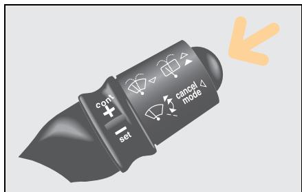
Cruise control*
From a speed of 30km / h the cruise control allows you to specify a speed that you would like to maintain, e.g. in order to comply with speed limits. The cruise control then automatically maintains this speed.
The cruise control is activated using the right control lever.
>Important!
Pressing the button on the control lever once or pushing the brake pedal will immediately deactivate the cruise control function and activate the limiter function.

Accident risk!
Only set the saved speed if it is safe to do so. Otherwise, sudden acceleration or braking could endanger yourself or others.
Labels on the control lever
- SET: for setting
- CONT: for continuing
- CANCEL MODE: clears operating mode

Accident risk!
The cruise control is intended solely as an aid to easier driving. You are responsible for the vehicle's speed and for braking in good time.
Cruise control is unable to take account of the road and traffic conditions. Do not use cruise control:
- in road and traffic conditions which do not allow you to maintain a constant speed (e.g. heavy traffic or winding roads). You could otherwise cause an accident.
- on slippery roads. The drive wheels could lose traction when braking or accelerating and the vehicle could skid.
- when there is poor visibility, e.g. due to fog, heavy rain or snow.
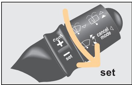
To activate the cruise control
Bring your car up to the desired speed.
Turn the ring switch towards
The desired driving speed is automatically held and stored.
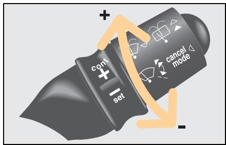
Altering speed selected via the cruise control
The set driving speed can be changed with the ring switch. Decelerating using the ring switch will bring the speed down only to 30km / h
Turn the ring switch towards

The speed is increased.
Turn the ring switch towards
The speed is reduced.

>Note!
The driving speed set using the ring switch also can be stored by turning towards
Cruise control*
Deactivating the cruise control
The cruise control is switched off:
- when braking.
- when the esp system is in operation.
- when the control lever is pressed one time.
The driving speed last set with the cruise control is stored.
>Note!
The speed last memorised is erased when you turn off the engine.
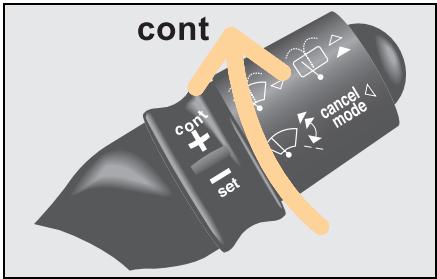
Resuming the stored driving speed
If you would like to resume the stored driving speed:
Turn the ring switch at the end of the control lever towards + .
The car is automatically accelerated or braked to the speed last memorised.
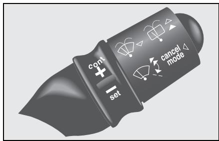
Speed limiter*
The speed limiter enables you to specify any permissible speed from 30km / h as your speed limit, but to vary the speed up to this limit by accelerating and braking.
The speed limiter function can only be set if the engine is running.
The speed limiter is activated using the right control lever.
>Important!
Pressing the button on the control lever once will immediately deactivate the limiter function and activate the cruise control function.
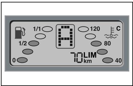
Switching on the speed limiter
Press the control lever for approx. 2 seconds.
The speed limiter is now switched on.
"LIM" and a speed value appear in the display.
Using for the first time
When you use the function
- for the first time,
- for the first time since the battery has been reconnected,
three horizontal dashes appear which flash in conjunction with "LIM".
Turn the ring switch towards

The speed limiter function is switched on.
The display shows a speed that can be changed with the ring switch.
Speed limiter*
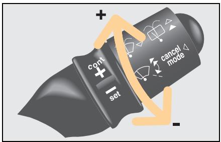
Setting the speed limit
Turn the ring switch towards cont or to set the speed limit.
The speed changes in increments of 5km / h
Driving with a speed limiter
You can accelerate your vehicle up to the set speed limit.
The engine is governed as soon as it reaches the upper limit.
Exceeding the specified limit speed
The specified speed limit may be exceeded if
- the car is accelerated while travelling downhill,
- you reduce the set speed limit using the ring switch, when your actual speed is higher than the new speed.
If the specified speed limit is exceeded by at least 10km / h
- a warning signal sounds,
- the speed limiter display starts to flash.
These warning signals cease once the set speed limit has been reached.
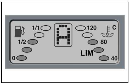
Temporarily switching off the speed limiter
In certain situations it may be necessary to temporarily switch off the speed limiter.
Press the control lever once.
The speed limiter function is switched off.
Only"LIM"appears in the display.
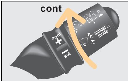
Reactivating the speed limit
You can reactivate the speed limit at any driving speed.
Turn the ring switch towards + .
The speed limit last stored re-appears in the display.
>Note!
The last speed selected for the speed limiter is stored when you switch off the engine. It can be called up directly the next time the engine is started.
>Note!
If you activate the kick-down function with the accelerator, the speed limiter function is switched off for safety reasons. You can exceed the specified limit if the situation requires.
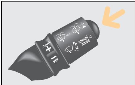
Switching off the speed limiter
Press the control lever for 2 seconds.
The speed limiter is now switched off.
The cruise control is switched on.
Brakes
Brakes
Handbrake

Danger of injury!
Never leave children unsupervised in the vehicle. They could release the hand brake. This could result in an accident and cause serious or even fatal injuries.

Accident risk!
Secure the vehicle against rolling away by pulling the hand brake. The vehicle could otherwise set itself in motion - even with the gearshift lever in position R - and cause an accident.
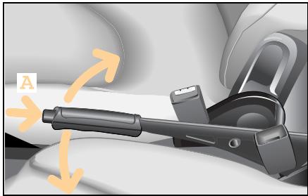
The handbrake serves to secure the car against rolling away when it is stationary or parked.
Operating the handbrake
Pull the lever upwards.
The lever engages automatically when pulled up.
Releasing the handbrake
Lift the lever up slightly.
Push lock knob (A).
Push the lever down.

Danger of injury!
The movement of the pedals must not be impaired in any way. Do not keep any objects in the driver footwell.
Make sure that there is sufficient clearance around the pedals when floor mats or carpets are used.
Always activate the handbrake when parking.
Never leave children unsupervised in the vehicle. They could move the gear lever and the vehicle could roll away on uphill or downhill gradients.
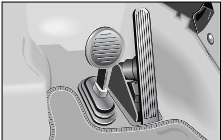
The footbrake has two brake circuits that are independent of each other. A brake servo is used during braking (when the engine is running) to increase pedal force.

Accident risk!
Considerably more effort will be required to apply the brakes if
- the brake servo has failed,
- a brake circuit has failed,
- the engine is switched off, e.g. for towing away.
The braking distance is likewise greater.
Make sure that the engine is running whenever the vehicle is rolling. Have the brake system repaired by a qualified specialist workshop, e.g. a smart center, if there is a fault in the brake system.
Brakes
If a brake circuit fails (see "Brake system faults", page 164),
>Note!
The brake servo will function only with the engine switched on.

Accident risk!
In the event of the car needing to be towed, a significantly greater amount of pedal pressure will be required when the engine is switched off.
The mechanical-acoustic brake pad display
The car is equipped with a mechanical-acoustic brake pad display. If you can hear a continuous noise from the front axle when braking, you should take the car to a qualified specialist workshop, e.g. a smart center.
Hydraulic brake assistant
The hydraulic brake assistant is activated in emergency braking situations. When you quickly depress the brake pedal (but without applying sufficient force), the hydraulic brake assistant automatically amplifies the brake force, thereby decreasing the braking distance.
Depress and hold the brake pedal until the emergency braking situation has passed.
abs will prevent the wheels from locking up.
When you release the brake pedal, the brakes will function as they normally would.
The hydraulic brake assistant is then deactivated.
Anti-lock braking system (abs)

Accident risk!
The risk of an accident especially increases when driving too fast, particularly when cornering and on wet or slippery roads as well as when driving too closely to the vehicle in front. abs and esp are unable to reduce this risk or override the laws of physics. You should therefore always adapt your driving style to suit the prevailing road and weather conditions and maintain a sufficient distance from other road users and objects on the road.
The anti-lock braking system (abs) prevents the braked wheels from blocking. Steering control is retained and you can therefore take evasive action to avoid obstacles.
>Important!
- The abs system has intervened when the brake pedal starts to pulsate.
abs is only effective during emergency braking manoeuvres when at least one wheel starts to lock up.
Braking using abs
In emergency situations:
- Quickly depress the brake pedal as hard as you can.
Steer around the obstacle.
The vehicle remains under control.
>Note!
Continue to apply the brakes even when the pedal starts to pulsate. This way you will achieve maximum deceleration.
Brakes

Faults in the brake system
A brake system fault has occurred if the brake system indicator light
- does not go out after releasing the handbrake.
- comes on when the car is in motion.
- comes on at the same time as the abs indicator light.
In all three cases
- Immediately park your car away from moving traffic.
- Secure your car against rolling away if you have to leave it.
Do not drive any further.
- Call a breakdown recovery service such as smartmove Assistance or a qualified specialist workshop such as a smart center.

Faults in the abs system
An abs malfunction has occurred if the abs indicator light
- does not go out again when the engine has started or within 10 seconds of having started (case 1).
- comes on when the car is in motion (abs emergency) (case 2).
- comes on together with the brake indicator light (abs malfunction) (case 3).
In cases 1 and 2
Take the car to a qualified specialist workshop, e.g. a smart center, without delay.
In case 3
- Immediately park your car away from moving traffic.
- Secure your car against rolling away if you have to leave it.
Do not drive any further.
- Call a breakdown recovery service such as smartmove Assistance or a qualified specialist workshop such as a smart center.
Electronic Stability Program (esp)
Electronic Stability Program (esp)
How esp works

Accident risk!
In critical driving situations,
esp stabilises the car's response subject to the laws of physics.
On no account can the system be expected to help prevent accidents if the car's speed is too high or the driver is reckless.
As such, always adapt your driving style to the prevailing road and weather conditions.
The car is equipped with the Electronic Stability Program (esp) as standard. esp monitors the driving stability and traction, i.e. the transmission of power between the tyres and the road.

Accident risk!
If the esp warning light in the instrument cluster flashes, proceed as follows:
Only depress the accelerator pedal as far as necessary when pulling away.
■ Accelerate less when driving.
Adapt your driving style to the road, traffic and weather conditions.
Otherwise the vehicle could begin to skid.
esp is unable to reduce the risk of an accident if you are driving too fast.
esp actively intervenes in the following driving situations:
- Evasive action if you suddenly encounter an obstruction
- Excessive cornering speeds
- Spinning of the driven wheels when moving away
>Note!
The indicator light in the instrument cluster flashes while esp is active. esp detects when a wheel spins and when the vehicle starts to skid.
Depending on the driving situation
- esp will reduce the speed.
- esp selectively brakes individual wheels.
- esp equalises the speed of the driven wheels.
- esp stabilises the vehicle when braking.
- esp assists you when taking evasive action on wet or slippery roads.
>Important notes for cars with esp!
Active braking intervention by esp will otherwise destroy the brake system on the rear axle.
- esp will only function properly if you fit the recommended tyre sizes on the wheels.
Airbags
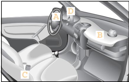
Airbags
Airbags reduce the severity of injuries in serious collisions, e.g. in a head-on collision or a side impact.
The airbag system consists of
- driver airbag (A),
- passenger airbag (B),
- sideairbags* (C),
- airbag indicator light (D).

Danger of injury!
In conjunction with a correctly fastened seat belt, airbags afford additional protective potential. However, they are no substitute for the seat belts.
To reduce the risk of serious or fatal injuries in an accident involving rapid deceleration, e.g. with an airbag inflating within a matter of milliseconds, or if the brakes are applied abruptly, please note the following:
- All vehicle occupants must select a seat position that allows the seat belt to be worn correctly and that is as far away from the airbag as possible. The driver's seat position must allow the vehicle to be driven safely. The driver's arms must be slightly bent when holding the steering wheel. The driver must maintain a distance from the pedals that allows him to depress these fully.
-
Choose a seat position that is as far as possible from the front airbag but nevertheless allows you to maintain control of the car reliably.
-
Vehicle occupants should always wear their seat belt correctly and position their backrest as close to the vertical as possible. The head restraint should support the back of your head at about eye level.
- Position the front passenger seat as far back as possible, particularly if children wearing child restraint systems* are secured to it.
- Excluding the smart baby carrier, do not secure rearward-facing child seats on the passenger seat, as doing so will not disable the passenger front airbag. Forward-facing child restraint systems may only be fitted to the front passenger seat if it is moved to its rearmost position.
- Do not lean forward, e.g. over the cushioned pad on the steering wheel, particularly while driving.
- Do not put your feet on the dashboard.
-
Only hold the steering wheel by the rim. This allows the airbag to inflate fully. You could be injured if the airbag is triggered and you are holding the inside of the steering wheel.
-
Do not lean on the doors from inside the vehicle.
- Do not place any objects on the airbags or between the airbags and the vehicle's occupants.
- Do not hang any hard objects such as coat hangers from the grab handles or coat hooks.
In view of the unavoidably high inflation speed of the airbag, the possibility of injuries when an airbag inflates cannot be entirely ruled out.
Airbag operating principle
The airbag is inflated in a matter of milliseconds. The airbag indicator light comes on.
>Note!
If the airbags are activated, you will hear a loud noise and some dust may be generated. The explosion fundamentally represents no risk to your hearing, and the dust is harmless.
The inflated airbag slows down and reduces the movement of the occupant. When the occupant makes contact with the airbag, hot gas flows out of the inflated front airbags and side airbags. This reduces the load on the occupant's head and upper body. These airbags are consequently deflated after the accident.
Airbags

Danger of injury!
After an airbag has been trig-
gered:
- airbag components will be hot. Do not touch them, or you could be burned
- the airbags must be changed by a qualified specialist workshop, which will have the necessary expertise and tools for performing the work involved. smart gmbh recommends that you visit a smart center for this. In particular, work relevant to safety or on safety-related systems must be carried out at a qualified specialist workshop.
Danger of injury!
A small amount of powder is released when an airbag inflates. This powder is not hazardous to health and does not indicate that there is a fire in the vehicle. The powder could cause short-term breathing difficulties in people with asthma or breathing problems. To avoid these breathing difficulties, such persons should either leave the car immediately (provided it is safe to do so) or open the window to let fresh air in.

Danger of injury!
For safety reasons,smart gmbh recommends that you use seat covers that have been tested for use in smart vehicles and which are fitted with a special tear seam for side airbags. A side airbag could otherwise fail to deploy correctly and achieve its intended protective potential in the event of an accident. These covers can be obtained at a smart center,for example.
Driver airbag/front passenger airbag
The front airbags are intended to increase the prospects of protecting the driver and front passenger against injuries to the head or thorax. The front airbags for the driver and front passenger are activated:
- at the start of an accident with high vehicle deceleration or acceleration in the longitudinal direction,
- if there is the prospect of supplementing the protective potential of the seat belt,
- if the seat belt is in use,
- independently of other airbags in the car being deployed,
- the airbags are not activated in the event of a rollover, unless high vehicle deceleration in the longitudinal direction is detected.
The front passenger front airbag is only activated if
- the front passenger seat is in use or occupied,
- the front passenger front airbag has not been manually disabled.

Danger of injury!
If the airbag indicator light
does not come on when a baby carrier is fitted to the passenger seat, the passenger airbag has not been deactivated. If the passenger airbag has not been deactivated, a child could sustain serious or even fatal injuries in the event of the airbag on the passenger side being triggered, particularly if the child is in the immediate vicinity of the passenger airbag at the time of its activation.
The passenger airbag is only deactivated when you fit an original smart baby carrier to the passenger's seat.
Side airbags*
Danger of injury!
To minimise the risk of injury if a side airbag deploys, you should ensure that
- there are no other persons, animals or objects between the vehicle occupants and the inflation range of the side airbag.
- only lightweight garments are hung from the clothes hooks in the car.
- there are no heavy or sharp objects in the pockets of items of clothing.
Airbags

Danger of injury!
Observe the following notes to reduce the risk of serious or fatal injuries if the side airbag deploys:
- Occupants - particularly children - should never rest their head on the area around the window from which the side airbag could emerge if deployed.
- Vehicle occupants must always wear their seat belt correctly and position their backrest as close to the vertical as possible.
- Always secure children under 150 centimetres tall and under twelve years of age with suitable child restraint systems.
The side airbags are integrated into the driver and front passenger seat backrests. If activated, they are intended to increase the potential protection for the thorax (but not the head, neck and arms) of the occupants on the side of the car that is struck.
The side airbags are activated:
- on the side of the car that is struck,
- at the start of an accident with high vehicle deceleration or acceleration acting in a lateral direction, e.g. a side impact,
- if there is the prospect of supplementing the protective potential of the seat belt,
- if the seat belt is in use,
- independently of the front airbags being deployed,
- independently of the belt tensioner,
- in situations excluding a rollover, unless high vehicle deceleration acting in the transverse direction is detected, coupled with the prospect of supplementing the protective potential.
>Note!
In the event of a side impact, the side airbags will only deploy when the airbag indicator light does not flash or illuminate.

Danger of injury!
If the airbag indicator light does not come on when a baby carrier is fitted to the passenger seat, the side airbag has not been deactivated. If the side airbag has not been deactivated, a child could sustain serious or even fatal injuries in the event of the side airbag being triggered, particularly if the child is in the immediate vicinity of the side airbag at the time of its activation.
The side airbag is only deactivated when you fit a special smart baby carrier to the passenger seat.

Airbag indicator light
The airbag indicator light signals to you that there is a fault in one or more of the following safety systems:
-airbag,
- belt tensioners,
- child seat recognition system.
The airbag indicator light comes on after switching the ignition on.
The subsequent self-diagnosis of the safety systems yields the following results:
- The airbag indicator light goes out after a maximum of 4 seconds.
No fault detected.
The airbag system is OK.
- The airbag indicator light flashes for 15 seconds, then illuminates permanently:
A smart baby carrier (original smart accessory) was identified on the passenger seat.
The passenger airbag, passenger's belt tensioner and the passenger side airbag are deactivated.
- The airbag indicator light goes out after a maximum of 4 seconds for approximately 1 second, then it comes on again and stays on.
A fault was detected (airbag warning).
or
The airbag indicator light flashes permanently.
A fault was detected in the child seat recognition system (airbag warning).
- Do not sit on the front passenger seat; this applies in particular to children.
Take the car to a qualified specialist workshop, e.g. a smart center.

Danger of injury!
If the airbag indicator light does not come on when a baby carrier is fitted to the passenger seat, the passenger airbag has not been deactivated. If the passenger airbag has not been deactivated, a child could sustain serious or even fatal injuries in the event of the airbag on the passenger side being triggered, particularly if the child is in the immediate vicinity of the passenger airbag at the time of its activation.
The passenger airbag is only deactivated when you fit an original smart baby carrier to the passenger's seat.
Airbags

Danger of injury!
For this reason, you should never carry a child on the passenger seat in a child restraint system that faces to the rear if the passenger airbag has not been deactivated, i.e. if the airbag indicator light is not lit.
Also observe the corresponding warning sticker on the instrument panel. If you have installed an original smart baby carrier on the passenger seat and the airbag indicator light does not come on (restraint system not identified), have the automatic restraint system recognition function checked without delay by a qualified specialist workshop, such as a smart center. Until this problem has been rectified, do not carry children in the car, as they could sustain serious or even fatal injuries in the event of an accident.
>Important!
If the airbag indicator light comes on during a journey, take the car to a qualified specialist workshop, e.g. a smart center, without delay.
It is possible that the airbag and the belt tensioner could be activated unintentionally or will not function in the event of an accident.

Danger of injury!
If the indicator light does not come on when you switch on the ignition or does not go out again after a few seconds once the engine is running or comes on again, there is a fault. Some systems could be triggered unintentionally or not be triggered at all in the event of an accident with high deceleration. In such cases, immediately have the safety system of your vehicle checked and repaired at a qualified specialist workshop which has the necessary specialist knowledge and tools to carry out the work required. smart gmbh recommends that you visit a smart center for this. In particular, work relevant to safety or on safety-related systems must be carried out at a qualified specialist workshop.
Contents
Storage compartments and trays 174
Luggage compartment. 183
Luggage compartment cover*.188
Luggage net bag* 190
Divider* between the luggage and passenger compartments (coupe) 193
Divider* between the luggage and passenger compartments (cabrio) 195
Multifunction box* 197
Rear rack* 198
Loading guidelines 199
>>Loading up.
How about going shopping? Parking space is not a problem with your vehicle - rest assured, you will find one!
Some coins for the parking meter? Now, let's start shopping!
Smaller objects can easily be put away in the storage compartments and trays. An entire weekend's worth of shopping can fit into the storage space behind the seats.
Storage compartments and trays
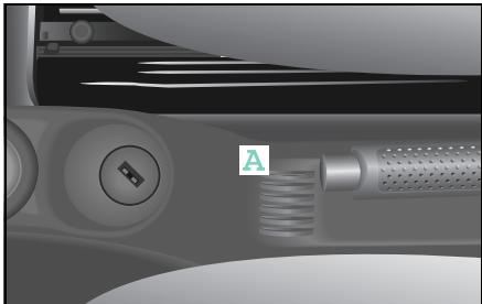
Storage compartments and trays
Coin slots
Your vehicle has handy slots for coins for
- supermarket trolleys,
parking meters,
- and pay telephones
in a place that is easy to reach.
Storage compartments and trays
Lockable storage compartment* under the driver seat

Danger of accident injury!
Do not store items weighing more than 2kg in the storage compartment. In the event of a collision or sudden braking manoeuvre, the storage compartment could otherwise be destroyed and items could fly out of the storage compartment into the footwell, potentially causing injury to the driver. The driver also could be distracted from driving by the flying objects and cause an accident.

Accident risk!
Only open and close the storage compartment when the vehicle is at a standstill. You otherwise risk being distracted from traffic and can cause an accident.

Danger of injury!
Always properly close the storage compartment. In the event of a collision or sudden braking manoeuvre, items could fly out of the storage compartment and into the footwell, potentially causing injury to the driver.

Danger of injury!
Keep the storage compartment area under the driver seat free of objects. Otherwise the storage compartment will not shut properly. If the storage compartment is not fully closed, it may unexpectedly open and cause injury en route.
Opening the storage compartment
Turn the rotary knob anticlockwise and slide the compartment out.
Closing the storage compartment
- Slide the storage compartment in.
The storage compartment is locked back into position when you hear a distinct "click".
>Important!
For safety reasons, conversions and modifications to the storage compartment are not allowed.
If the storage compartment unexpectedly opens, the driver may be startled and react inappropriately, thereby causing an accident.
Storage compartments and trays
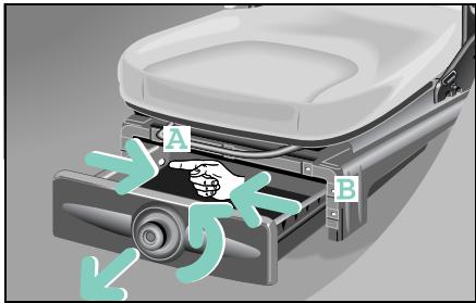
Removing the storage compartment
- Open the storage compartment until it stops.
Using your forefinger, reach into shackle A and pull it inwards.
Simultaneously pull the storage compartment forward a little, out of the mounting point.
Repeat this process with tab (B).
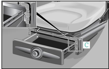
Inserting the storage compartment
Ensure that there are no objects lying around the storage compartment area under the driver seat.
Position the storage compartment rail in the rail guide (C).
- Close the storage compartment.
Storage compartments and trays
Ashtray

Fire hazard!
Never use the ashtray as a place to deposit paper or other flammable material.
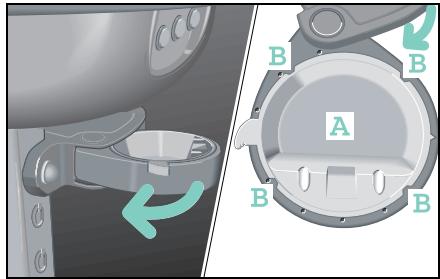
Emptying and cleaning
When cleaning the ashtray, use a wet cloth only.
- Swivel the frame out as far as it will go.
Press tray (A) upwards out of the frame.
After cleaning, press the tray and frame together so that the four clips (B) engage.
The frame can be swivelled back.
Storage compartments and trays
Drinks holder*
Danger of injury! Make sure that any objects placed in the drinks holder are always secure while the car is moving. Vehicle occupants could be injured by objects being thrown around in the vehicle in the event of:
- Severe braking
- A change of direction
- An accident
Only use the cup holders for containers of the right size and which have lids. Otherwise, the drinks could spill.
Cup holders should not be used for hot drinks. Otherwise, you may scald yourself.
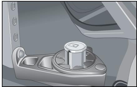
While en route:
- use the drinks holder to store your beverage cans and bottles safely, as well as other suitable objects.
- keep the drinks holder ring closed.
>Note!
Do not use the drinks holder as an ashtray, as this can damage it.
>Important!
For safety reasons, conversions and modifications to the drinks holder are not allowed.
Storage compartments and trays
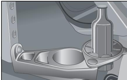
When the vehicle is at a standstill (e.g. a picnic),
- you can pivot the drinks holder ring to the right and place drink bottles on the vehicle floor.
- you can also make use of the large area in the drinks holder.
Cleaning
When cleaning the drinks holder, use a wet cloth only. You can remove the insert to clean.
- Swing the drinks holder ring out to the right as far as the outermost snap-in position.
Remove the insert by pulling it up and out.
After cleaning, place the insert back into the housing.
The drinks holder ring can be swivelled back.
Storage compartments and trays
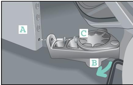
Installed position
- Between the driver and passenger foot-wells
- Always in the lowest position in the vertical console
>Note!
If you also have purchased the cassette box* or CD box*, always fit the drinks holder last.

Accident risk!
After driving approx. 10km check that the drinks holder is firmly positioned and retighten the retaining screws if necessary. If this is not done, the drinks holder could work loose and fall into the driver footwell.
Installing and removing
Guide the drinks holder diagonally from above towards the lowest mounting in the vertical console.
- Place the drinks holder on the centre console. When you do this
- the drinks holder housing must rest against the vertical console (A).
- the lateral guides (B) of the drinks holder must rest against the centre tunnel.
Press the drinks holder firmly against the carpet.
Screw the drinks holder hand-tight with a coin.
- Check that the housing is located securely and fit the cover cap (C).
>Note!
Removal is done in the reverse order.
Storage compartments and trays
Door pocket nets*
The door pocket nets*
- are located on the door trim on the driver and passenger sides.
- are flexible and able to be stretched for storing small objects that you might wish to keep immediately to hand.
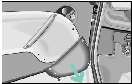
Installing/removing
- Unscrew the four retaining screws from the existing door pockets and remove the pockets.
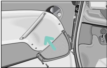
Screw the new door pocket nets into place with the retaining screws.
>Note!
The retaining screws may only be tightened hand-tight (2 Nm).
Storage compartments and trays

Danger of injury!
Do not transport unsecured heavy objects in the interior or luggage compartment. Vehicle occupants could be injured by objects being thrown around in the vehicle in the event of:
- Severe braking
- A change of direction
- An accident
Even if you follow all the loading guidelines, the load will increase the risk of injury in the event of an accident.
The storage bag in the front passenger footwell is only suitable for storing lightweight items. Heavy, sharp-edged or fragile objects should not be transported in the bag. The bag is unable to retain such items in the event of an accident.
Securing the storage bag
Danger of injury!
The storage bag may only be secured in the passenger footwell. The storage bag otherwise could work loose, fall into the driver footwell and land between the pedals. At this point, you no longer would be able to brake, engage the clutch or accelerate as intended. This can lead to accidents and injuries.
Place the side of the bag with the velcro on the carpeting in front of the passenger seat.
■ Firmly press down on the bag with your hand.
Luggage compartment
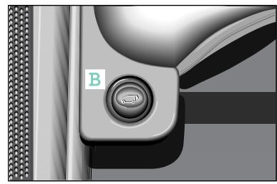
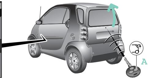
Luggage compartment
Unlocking the upper tailgate of the smart fortwo coupé

Danger of poisoning!
Keep the tailgate closed while the vehicle is in motion. Otherwise, exhaust fumes could get into the vehicle interior and poison you.
Press button (A) on the remote control for 2 seconds.
or
■ unlock the tailgate mechanically. or
press the unlock button (B) on the inside.
Press the unlocking button.
The tailgate is unlocked.
- Fold the upper flap of the tailgate upwards.
>Note!
This function only can be used when the central locking system is deactivated and the vehicle is at a standstill.

Danger of injury!
Do not transport unsecured heavy objects in the interior or luggage compartment. Vehicle occupants could be injured by objects being thrown around in the vehicle in the event of:
- Severe braking
- A change of direction
- An accident
Even if you follow all the loading guidelines, the load will increase the risk of injury in the event of an accident.
Luggage compartment
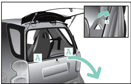
Unlocking the lower tailgate of the smart fortwo coupé
Pull both release levers (A) at the same time or successively towards you.
The lower tailgate is unlocked. It can be lowered and is held in place in the horizontal position by the two retaining straps.
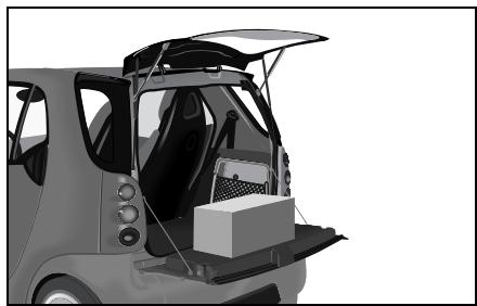
>Note!
When folded down the lower tailgate flap can bear loads up to a max. 100kg The maximum permissible load in the luggage compartment is 50~kg
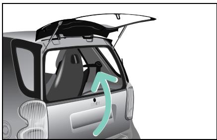
Closing the tailgates

Danger of injury!
When closing the tailgate, make sure that no one is trapped.
- Lift the lower tailgate back up and make sure that the two release levers audibly engage.
Pull down the top tailgate section and close it firmly.
Luggage compartment
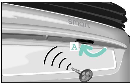
Unlocking the tailgate of the smart fortwo cabrio
■ Unlock the car with the remote control.
The tailgate now can be unlatched and opened using the door handle recess (A).
or
Mechanically unlock the tailgate from the outside.
>Note!
The lock barrel is supplied ex works with a rubber cover cap.
The anti-theft alarm system must be deactivated by pressing the button on the key before the tailgate can be opened mechanically.
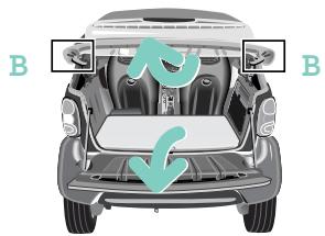
Folding up the rear soft top
The rear soft top can be folded up to ease loading and unloading.
Push up the release levers (B) at the right and left on the retaining clip.
Now, fold up the rear soft top.
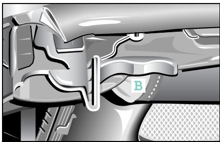
>Note!
The retaining clip is self-locking in the upper position.
>Important!
Before closing the tailgate, the rear soft top must first be locked in place; otherwise the release levers may break.
Luggage compartment
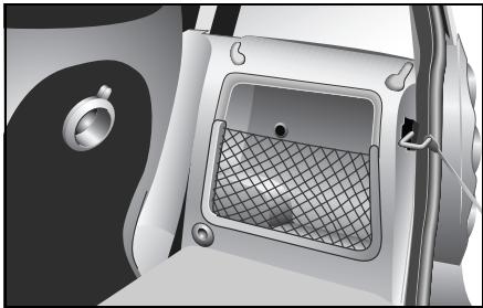
Luggage net
On the right-hand side of the luggage compartment is a compartment with a luggage net which serves to provide additional storage space for small objects. This compartment is large enough to hold the warning waistcoat and the first aid pouch. The hazard warning triangle can be secured anywhere in the luggage compartment by means of the velcro fastener.
>Note!
The luggage net is only suitable for storing lightweight items.
Heavy, sharp-edged or fragile objects should not be transported in the luggage net.
The luggage net is unable to retain such items in the event of an accident.
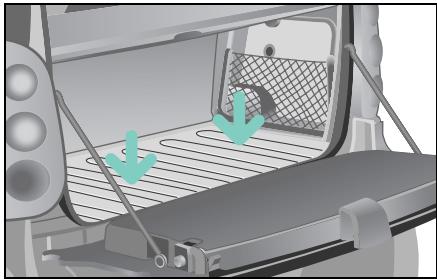
Boot tub/dirt tub*
To protect the luggage compartment floor from dirt or damage, you can secure the boot tub/dirt tub to the luggage compartment floor with the aid of velcro.
Luggage compartment

Danger of injury!
Do not transport unsecured heavy objects in the interior or luggage compartment. Vehicle occupants could be injured by objects being thrown around in the vehicle in the event of:
- Severe braking
- A change of direction
- An accident
Even if you follow all the loading guidelines, the load will increase the risk of injury in the event of an accident.
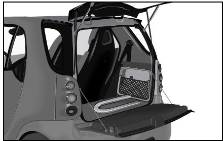
Luggage wedge*
You can use the luggage wedge to stop smaller objects from sliding around in the luggage compartment while in transit.
Securing the luggage wedge
- Secure the luggage wedge to the luggage compartment floor with the velcro.
Luggage compartment cover*
Luggage compartment cover*

Accident risk!
The luggage compartment cover is not intended to secure heavy objects in the event of an accident. For this reason, heavy objects must be tied down.

Danger of injury!
Do not transport any objects by placing them on the mounted luggage compartment cover. Vehicle occupants could be injured by objects being thrown around in the vehicle in the event of:
- Severe braking
- A change of direction
- An accident
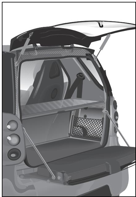
The luggage compartment cover
- serves to protect objects that are stored in the car's luggage compartment from prying eyes.
- prevents smaller objects from penetrating into the passenger compartment from the storage space area, however it is not intended to act as a load restraining device.
>Note!
If objects are placed on the luggage compartment cover when mounted, the cover may be damaged.
Luggage compartment cover*
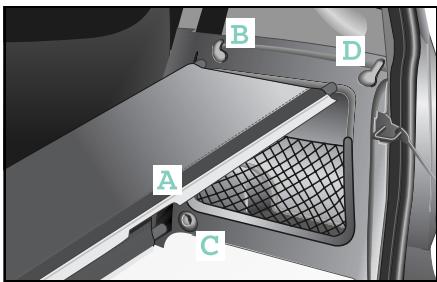
Fitting the luggage compartment cover
>Note!
The luggage compartment cover has to be fitted in such a way that
- section (A) is in the indicated position,
-
the structured side is facing upwards.
-
Place the centre rod in the left and right-hand sides of the side panelling mount (B).
Insert the front rod into the mounting (C) on the left-hand side panelling.
Insert the other side of the front rod into the mounting (C) on the right-hand side panelling.
Tension the luggage compartment cover by inserting the rear rods at the left and right into the mounting (D) of the side panelling.
Removal is done in the reverse order.
Luggage net bag*
Luggage net bag*

Accident risk!
Only place light loads in the luggage net. Do not transport heavy, sharpened or fragile objects in the luggage net. The luggage net cannot sufficiently secure loads in an accident. Please note the loading guidelines on page 199 and the divider topic on page 193.
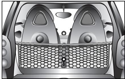
The luggage net bag
- is for storing small, lightweight objects.
- prevents small objects from sliding around inside the passenger or luggage compartment.
- can be removed and used as a carrying net.
Fitting the luggage net bag
The luggage net bag can be mounted in two positions:
- Open towards the front: The luggage net bag can be accessed between the seats in the passenger compartment
- Open towards the rear: The luggage net bag can be accessed from the luggage compartment
Fitting without luggage compartment cover
If your car does not have a luggage compartment cover, you will need an additional rod, which can be supplied by a qualified specialist workshop such as a smart center.
Connect the included hooks to the rod.
Continue with step 3 of the instructions for fitting the compartment cover.
- Secure the net to the rod with the upper end of the velcro strip.
The luggage net bag is stabilised.
Fitting with luggage compartment cover The luggage net bag is secured to the front upper rod of the luggage compartment cover.
Remove the entire luggage compartment cover from the car.
Take the two end caps off the middle rod and replace them with the hooks enclosed with the luggage net bag.
Install the rod with the hooks or the entire luggage compartment cover in the car again.
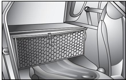
>Note!
If you wish the luggage net bag to be accessible from the front, the double hooks must be pointing forwards.
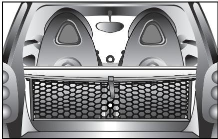
>Note!
If the luggage net bag is to be located beneath the luggage compartment cover or accessible from the luggage compartment, the hooks must point to the rear.
Luggage net bag*
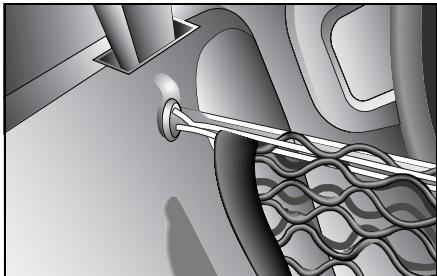
- Engage the luggage net bag in the double hooks by means of the loops of elasticated cord. Depending on the side from which the bag is to be accessed, the handle should point to the front or the rear.
Gently pull down the luggage net bag and press down the velcro to secure it to the luggage compartment base.
Divider* between the luggage and passenger compartments (coupe)
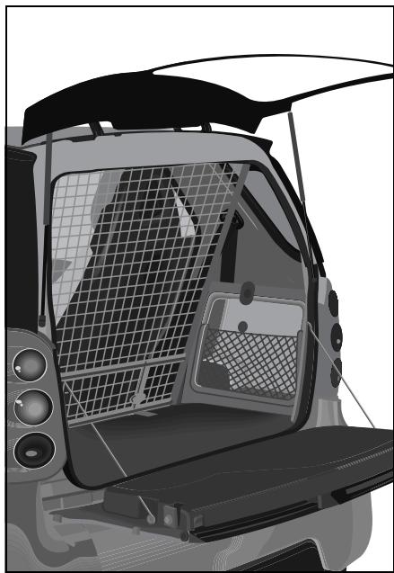
Divider* between the luggage and passenger compartments (coupe)
The divider between the luggage and passenger compartments is a restraint system for any items of luggage you may have in the storage space.
The divider between the luggage and passenger compartments is attached to four anchorage points in the car. These points are mounted in a qualified specialist workshop such as a smart center.

Danger of injury!
Do not use the divider between the luggage and passenger compartments if it is damaged. A damaged divider cannot sufficiently retain the load. Vehicle occupants could be injured by objects being thrown around in the vehicle in the event of:
- Severe braking
- A change of direction
- An accident
Divider* between the luggage and passenger compartments (coupe)
Fitting the divider between the luggage and passenger compartments

Danger of injury!
Make sure that the hooks are securely engaged and that the straps are drawn in hand-tight. Vehicle occupants could be injured by objects being thrown around in the vehicle in the event of:
- Severe braking
- A change of direction
- An accident
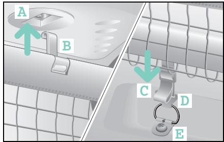
■ Engage the hooks (B) in the upper anchorage points (A).
Pull the tensioning straps (C) down.
Now insert the hooks (D) into the anchoring eyelets (E) bolted to the floor.
The lower section of the divider between the luggage and passenger compartments rests against the tensioning straps from behind.
>Note!
Do not use the divider if damaged!
Divider* between the luggage and passenger compartments (cabrio)
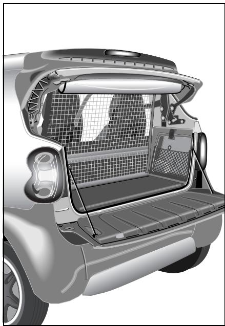
Divider* between the luggage and passenger compartments (cabrio)
The divider between the luggage and passenger compartments is a restraint system for any items of luggage you may have in the storage space.
The divider between the luggage and passenger compartments is attached at the top to the roll bar and at the bottom to the two anchoring eyelets. These anchoring eyelets are mounted in a qualified specialist workshop such as a smart center.
Fitting the divider between the luggage and passenger compartments
Danger of injury! Make sure that th
curely engaged and that the straps are drawn in hand-tight. Vehicle occupants could be injured by objects being thrown around in the vehicle in the event of:
- Severe braking
- A change of direction
- An accident
Divider* between the luggage and passenger compartments (cabrio)
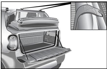
Place the belts' turnbuckles from the rear over the roll bar's covering.
Turn the catch (A) to the horizontal position.
Feed the lower belts through the turn-buckles.
Now insert the hooks into the eyelets bolted to the floor.
Fasten the divider between the luggage and passenger compartments by pulling uniformly on the belts.
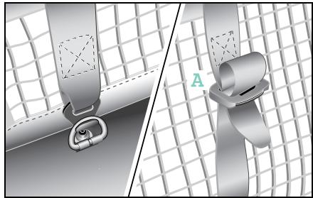
Removing the divider
To relieve the tension on the belt, simply turn the belt buckles until horizontal.
Slide the belts out.
The divider between the luggage and passenger compartments can now be unhooked and removed.
>Note!
Do not use the divider if damaged.
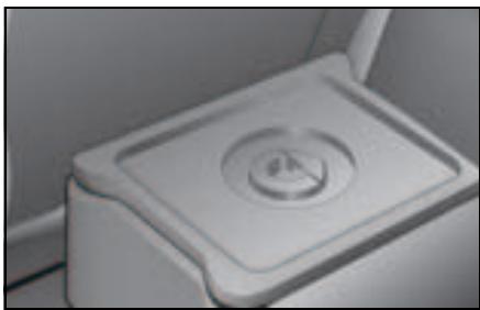
Multifunction box*
The multifunction box allows you to store smaller objects safely in a thermally insulated container. You can take the multifunction box out of the car and carry it around easily. It is consequently ideal for storing shopping. The lid can be completely detached.
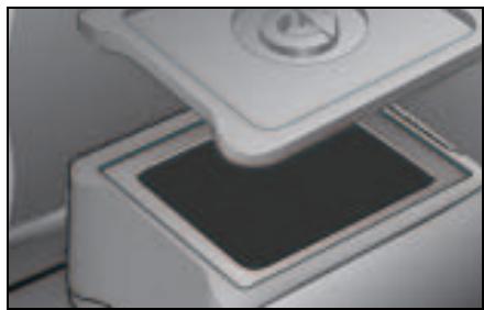
Danger of injury! Ensure that the multifunction box is always installed securely in the luggage compartment. It could otherwise be thrown forward in the event of an abrupt braking manoeuvre, a sudden change in direction or an accident and cause serious or even fatal injuries to occupants.
Rear rack*
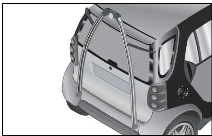
Rear rack*
The rear rack consists of a base rack* that can be extended by two special beams for the loading of e.g. bicycles and skis. All of the carrier beams are rust-free, protected against theft by multi-point head screws and are easy to mount.
>Note!
More information on operating and installing the base rack, bicycle rack and ski holder* can be found in the respective operating instructions.
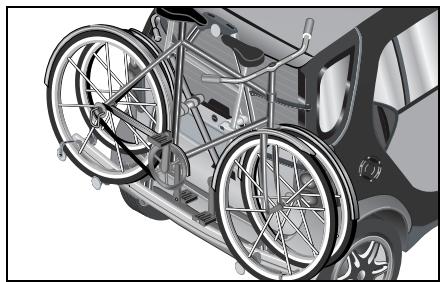
Base rack*
The base rack serves as the basis for additional special beams. This rack can be used to secure a load of up to 30kg .
Bicycle rack*
The bicycle rack, in conjunction with the base rack, can transport two bicycles up to 30kg
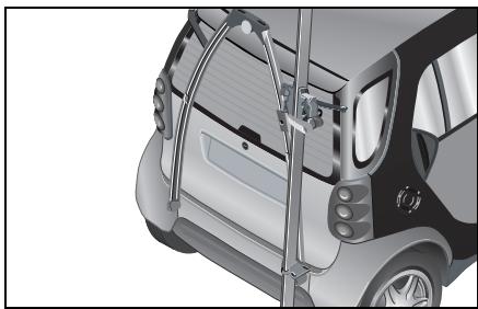
Ski holder*
The ski holder can take up to two skis or, as a Carving Kit*, carving skis.
Loading guidelines
Loading guidelines
| All fortwo coupés including
fortwo coupé from BRABUS | All fortwo cabrios including
fortwo cabrio from BRABUS |
| Curb weight1 (kg) | 805 | 815 |
| Load capacity (kg) | 260 | 250 |
| of which maximum load in the luggage compartment
(kg) | 50 | 50 |
| Permissible gross vehicle weight (kg) | 990 | 990 |
| Luggage compartment volume (l) | 150 - 3632 | 150 |
| Luggage compartment volume up to the roof (ltrs.) | 260 | - |
- Curb weight (acc. to 92/21/EEC) including driver (75 kg) and all operating fluids (tank 90 % full). Optional extras will increase the curb weight; as a result the payload is reduced.
2With passenger seat folded down.
>Note!
More information on "Dimensions and
weights" is available from page 274.
Loading guidelines

Accident risk!
The manufacturer has not approved your car for towing a trailer. A trailer can permanently impair driving safety and reliability.

Danger of accident injury!
No support beams or loads may be secured to the roof of the vehicle,
- as the glass roof (if equipped) could be destroyed and possibly injure the vehicle's occupants.
- as this can have a substantial adverse effect on the driving dynamics of the vehicle, thus provoking accidents.
Reduced payload
Optional extras and accessories increase the curb weight, which in turn reduce payload.
Mounting a base carrier, bicycle carrier and a ski carrier at the rear of the car will result in the manufacturer's axle load distribution changing.
Please study the operating instructions for each individual accessory part!
You must observe the following:
- Your car's handling characteristics are dependent upon the load distribution.
- Do not exceed the permissible gross vehicle weight and permissible axle load by loading too much into the car (take occupants into account).
- Do not stack loads higher than the top edge of the head restraints.
- Make sure that loaded articles are properly secured.
- When loading, put the heavy items at the bottom and the light ones on top.
- To transport heavy or small items safely, you should use the original smart divider accessory which is installed between the luggage and passenger compartments.
Loading guidelines

Danger of injury!
Always lash down the load. It
could otherwise be thrown forward in the event of an abrupt braking manoeuvre, a sudden change in direction or an accident and cause serious or even fatal injuries to occupants.
Danger of injury!
Transport heavy or hard objects in the luggage compartment, not the passenger compartment. Vehicle occupants could be injured by objects being thrown around in the vehicle in the event of:
- Severe braking
- A change of direction
- An accident

Accident risk!
The permissible gross vehicle weight and the permissible axle load must not be exceeded by the payload (interior and roof rack), including the occupants. Overloading or incorrectly loading the vehicle impairs driving stability, and the altered road behaviour could result in tyre damage! This poses the risk of accidents.

- Severe braking
- A change of direction
- An accident

Danger of poisoning!
Keep the tailgate closed while
the vehicle is in motion. Otherwise, exhaust fumes could get into the vehicle interior and poison you.

Environment!
Do not carry any unnecessary ballast. Unnecessary ballast increases vehicle weight and fuel consumption.
Loading guidelines
Vehicles without a right outside mirror

Accident risk!
If your car does not have a passenger door mirror,
- the smart must not be loaded above the tailgate upper edge,
- a divider must not be installed between the luggage and passenger compartments,
- the car must not be fitted with a base carrier or bicycle carrier or have a ski carrier mounted at its rear.
This is because the view to the rear would otherwise be greatly impaired. Impaired visibility could endanger yourself and others. This may prevent you from observing the traffic conditions, thereby causing an accident.
Contents
Refuelling 204
0il level. 206
Checking operating fluids. 210
Tyre inflation pressure. 215
Wiper blades 218
Care notes. 219
>>Part-time jobs.
The small activities to do with your vehicle are a practical and necessary side job. This helps to maintain the traffic and operating safety of your car plus its value. Most of it can be done while at the petrol station.
Refuelling
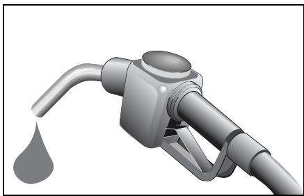

Danger of poisoning!
Keep fuel away from children. See
a doctor immediately if any fuel is swallowed.

Danger of injury!
Fuel is highly flammable. Fire, naked flames and smoking are therefore prohibited when handling fuels. Switch off the engine and the auxiliary heating* before refuelling.
Do not allow fuel to come into contact with skin or clothing. Fuel is hazardous to your health if it comes in direct contact with your skin or if you inhale the fuel vapours.
>Note!
The 55kW petrol engine (fortwo coupé from BRABUS) is designed to run on unleaded petrol with a minimum grade of 98 RON/88 MON.
In countries where no such petrol is available, you can refuel with 95 RON.
This, however, can reduce engine output and increase fuel consumption.
| Refuelling | Diesel engine | Petrol engines |
| fortwo coupé/
fortwo cabrio | fortwo coupé/
fortwo cabrio | fortwo coupé from BRABUS/
fortwo cabrio from BRABUS |
| Fuel tank | | | |
| Capacity (ltrs.) | 22 | 33 | 33 |
| of which reserve capacity (ltrs.) | 5 | 5 | 5 |
| Fuel | Diesel fuel EN 590 | Premium unleaded petrol, EN 228,
at least 95 RON/85 MON | Premium Plus unleaded petrol,
EN 228,
at least 98 RON/88 MON |
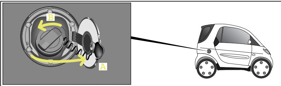
Refuelling properly
>Important!
- Never refuel a petrol engine with leaded petrol or diesel!
Do not start the engine.
Otherwise the catalytic converter will be irreparably damaged.
- Never refuel a diesel engine with petrol!
Do not start the engine.
The fuel system otherwise will be damaged.
In both cases, immediately call a qualified specialist workshop, e.g. a smart center or a breakdown recovery service such as smartmove Assistance and have the vehicle towed.
Switch both the engine and ignition off.
The fuel filler flap (A) is located on the right side of the vehicle and is locked and unlocked via the central locking system.
Turn the filler cap anticlockwise (B).
You should fill up with fuel until the nozzle cuts out.
Turn the filler cap clockwise until it is tight and the handle grip overturns.
Close the fuel filler flap.
>Note!
If you want to fill the fuel tank all the way to the top, wait 30 seconds after the first switch off, then start filling the tank with the fuel pump nozzle again until it switches off.

Environment!
Never allow fuel to spill over.
Never overfill the fuel tank.
Fuel that has spilled over onto the ground pollutes the environment.
Oil level
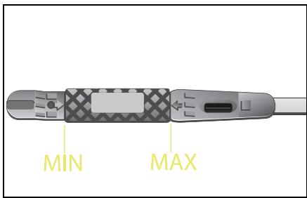
Oil level
Checking the engine oil level

Danger of poisoning!
Keep engine oil away from chil
dren. See a doctor immediately if any
engine oil is swallowed.
>Note!
Check the engine oil level at regular intervals when the engine is warm.
Park the car on a level surface.
Switch both the engine and ignition off.
Apply the handbrake.
>Important!
- Observe the scheduled service intervals.
Failure to do so may destroy your engine.
- Observe the information in the service interval display.
- An oil level above the MAX mark may result in engine or catalytic converter damage. Oil quantities above the MAX mark have to be siphoned off.
- An oil level below the MIN mark may result in your engine being damaged.
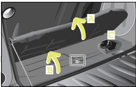
Checking engine oil level
Wait a few minutes until the oil has settled.
Opening the tailgate.
- Fold the carpet back (A).
Remove the fastening screw for the engine compartment cover (B).
Remove the engine compartment cover.
Pull the dipstick (C) out and wipe it with a clean cloth.
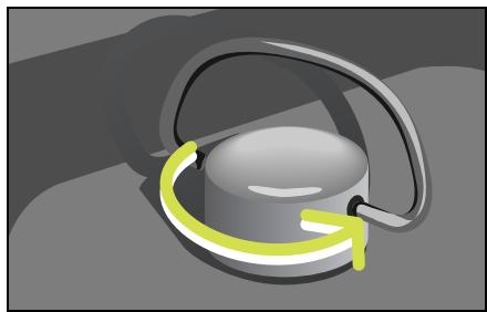
Reinsert the dipstick.
Wait for at least one minute.
Pull the dipstick out again.
The oil level must lie between the markings MIN and MAX on both sides of the dipstick.
Reinsert the dipstick.
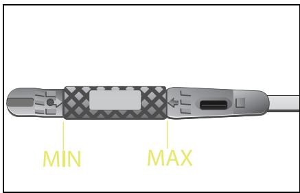
Oil level
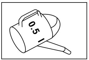
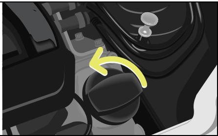
If your car has too little engine oil

Fire hazard!
When topping up the engine oil, take care to ensure that no oil is spilt on any hot parts such as the exhaust system or catalytic converter. If this should happen, however, the engine must be thoroughly cleaned off before you continue your journey. The oil could otherwise ignite.
You must top up the engine oil!
Unscrew the cap.
Use a funnel to top the engine oil up.
Top up with no more than 0.5 litres of engine oil.
smart recommends the use of Mobil engine oils or smartcare engine oil.
Wait a minute until the oil has run into the oil pan.
Check the engine oil level again.
Screw the cap on tightly in the clockwise direction.
- Slide the engine compartment cover forward into the tabs provided and tighten the fastening screw.
Return the carpet to its position.
Close the tailgate.
>Note!
The engine oil level should only be checked when the engine is still warm.
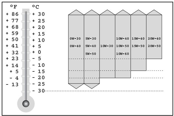
Choosing the right type of oil
Use only oils approved by smart gmbh (acc. to MB sheet 229.5). The MB sheet number is marked on the oil containers. A list of the approved engine oils can be obtained from any smart center or smart service.
>Important!
Do not use special additives. They may lead to increased wear or engine damage. A qualified specialist workshop such as a smart center will be able to provide further details.
Engine oil viscosity
The SAE class (viscosity) has to be chosen in accordance with the average outside air temperature for each current season. Exact adherence to the SAE classes according to the outside temperatures would, however, necessitate frequent oil changes. The temperature limits for the SAE classes therefore should be viewed as guidelines which can be temporarily exceeded or undercut.

Environment!
When topping up the oil, take care not to spill any. Oil must not be allowed to escape into the soil or waterways. You would otherwise be damaging the environment.
Checking operating fluids
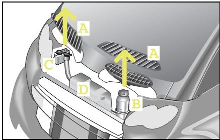
Checking operating fluids
If you open the service screen (A), you can check the fluid levels for the
- coolant (B),
- windscreen washer system (D),
- brake fluid (C).
Check the fill levels at regular intervals.
Before checking the fluid levels
Park the car on a level surface.
Switch both the engine and ignition off.
Apply the handbrake.
>Important!
Free the service screen carefully from snow and any other forms of dirt to ensure air intake at all times.
Checking operating fluids
Opening the service screen

Danger of injury!
Always switch off the ignition and remove the ignition key before opening the service screens. If the wipers should inadvertently be switched on, you could be seriously injured by the wiper washer drive, which is located just below the service screen.
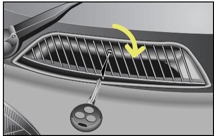
Turn the lock with the car keys towards the centre of the car.
The service screens are open.
Remove the service screen.
Remove the intake trumpet on the driver side.
>Important!
Try to avoid forcing open the service screen. The key could be damaged.
Closing the service screen
Push the service screen on the right and left-hand lower corners into the clips provided.
Use the car key to lock the service screen.
Checking operating fluids
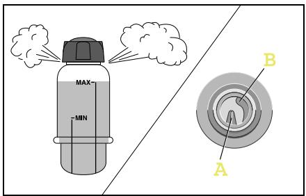
Checking the coolant level
Danger of injury! The cooling system is pres-surised. Therefore, only unscrew the cap once the engine has cooled down. Allow it to cool down for at least 30 minutes. You could otherwise be scalded by escaping hot coolant.
It is necessary to check the coolant level to ensure that the engine does not overheat.
>Important!
The cooling system is maintenance free under normal operating conditions. A drop in the coolant level indicates leakage.
If you are losing coolant
- Top up the coolant.
- Have the reason for the loss of coolant investigated by a qualified specialist workshop, e.g. a smart center.
Checking the coolant level
Let the radiator cool down for at least 30 minutes.
- Cover the cap for the coolant expansion reservoir with a cloth before touching it.
Turn the cap one complete revolution in order to allow the excess pressure to escape.
■ Unscrew the cap and remove it.
- Look down into the reservoir for a visual check.
In the reservoir, there are two ridges of different heights.
- The longer one (A) indicates the maximum filling level.
- The shorter one (B) indicates the minimum filling level.
Topping up the coolant
You should only top up the coolant as far as the maximum filling level.
Replace the cap and tighten when finished.
>Note!
Warm water expands, which is why it may extend beyond the maximum filling level.
Checking operating fluids
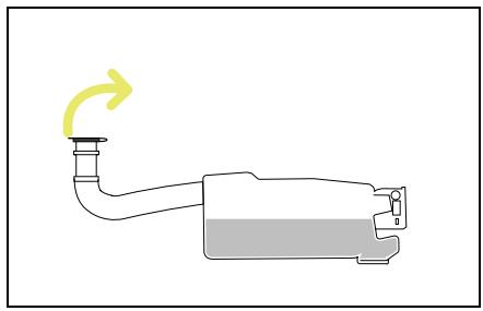
The windscreen washer reservoir has an approximate capacity of 3 litres.

Fire hazard!
Windscreen washer concentrate is highly flammable. Fire, naked flames and smoking are prohibited when windscreen washer concentrate is being handled.
Pull the filler neck upwards out of its holder.
Pull up the reservoir cap at the tab. > You can now add washer fluid.
>Note!
In order to clean the windscreen optimally, use smartcare windscreen cleanser concentrate for summer or winter.
Topping up the windscreen washer system
| Dosage for total filling quantity of 3 litres depending on the outside temperature | Above 0 °C | -10 °C | -20 °C |
| smartcare windscreen cleanser concentrate, summer: water | 1:100 | | |
| smartcare windscreen cleanser concentrate, winter: water | | 1:2 | 1:1 |
Compare with notes for use on packaging.
Checking operating fluids
Checking the brake fluid

Accident risk!
If the boiling point of the brake fluid is too low, vapour bubbles could form in the brake system when the brakes are subjected to high loads (e.g. when driving down mountain passes). This would impair braking efficiency. Have the brake fluid changed every two years!
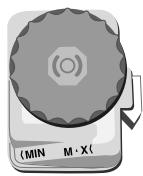
A constant fluid level is necessary to ensure that the car's brake system remains in perfect working order.
>Important!
Have the brake fluid topped up only by a qualified specialist workshop, e.g. in a smart center.
Checking the brake fluid level
- Look down into the reservoir for a visual check.
The fluid level must lie between the MIN and MAX marks.
If the level is slightly below the MIN mark, take your car to a qualified specialist workshop, e.g. a smart center.
If the level is significantly below the MIN mark, call a breakdown recovery service, e.g. smartmove Assistance or a qualified specialist workshop, such as a smart center.
Tyre inflation pressure
Tyre inflation pressure
Tyres are a particularly important aspect of the car's operating safety and roadworthiness. For this reason, you must check the tyre inflation pressure, tyre tread and tyre condition on a regular basis.

Accident risk!
If the inflation pressure of a tyre falls repeatedly,
- inspect the tyre for foreign objects.
- check whether the tyre is punctured or the valve is leaking.

Accident risk!
Insufficient tyre pressure leads
to
- excessive tyre heat build-up,
- increased tyre wear and an increased risk of causing an accident due to tyre pressure loss and changes to driving stability,
- increased fuel consumption.
High tyre pressure leads to
- a longer brake distance,
- poorer traction from all tyres and
- increased, uneven wear.
Tyres that are inflated too high are moreover more susceptible to damage and therefore increase the general risk of accidents.

Accident risk!
Always inflate your car's tyres to the specified pressures. The temperature and pressure of the tyres rise during operation. For this reason, never reduce the tyre pressure of tyres while warm. The pressure of the tyres would then be too low once they had cooled down. If tyre inflation pressure is too low, tyres could be damaged, particularly if the car is carrying a high load and is travelling at high speed.
Tyre damage could e.g. result in a tyre bursting, causing you to lose control over your car; you or others could be injured as a result.
You should therefore check the tyre inflation pressure regularly, but at least every 14 days.
Tyre inflation pressure
Check the tyre inflation pressure before the start of your journey. There is a table showing the tyre inflation pressure on your car's fuel filler flap.
>Note!
Tyre inflation pressures change by about 0.1 bar per 10^ change in the air temperature. Always keep the tyre inflation pressure at the recommended level.
Tyre inflation pressure
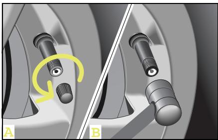
Checking the tyre inflation pressure
■ Allow the tyres to cool down.
■ Unscrew the valve protective cap (A).
Check the tyre pressure (B).
The tyre inflation pressure values are printed on the inside of the filler cap and in the table below.
Screw the protective cap back onto the valve.
>Important!
The protective cap protects the valve against dirt and leakage.
| Tyre inflation pressure (summer and winter) | (bar) |
| 135/70 R15 front - 175/55 R15 rear | 2.0 |
| 145/65 R15 front - 175/55 R15 rear | 2.0 |
| 175/55 R15 front - 195/55 R15 rear | 2.0 |
| 175/50 R16 front - 205/45 R16 rear | 1.8/2.3 |
| 175/50 R16 front - 225/35 R17 rear | 1.8/2.3 |
Wiper blades
Wiper blades
To have a clear view of things,
- wiper blades that are in perfect shape are absolutely indispensable,
clean the wiper blades regularly with a cleaner and
- remove any tough dirt stains with a sponge or brush.
>Note!
Original smart wiper blades for your car are available from a qualified specialist workshop, e.g. a smart center.
Changing the wiper blades

Danger of injury!
Remove the key from the ignition
lock before replacing the wiper blades.
The windscreen wipers could otherwise
be set in motion and injure you.
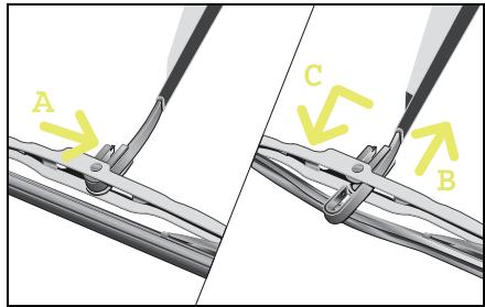
Take the keys out of the ignition switch.
- Fold the wiper blade arm up and turn the wiper blade until it is horizontal.
Press the retaining spring (A).
- Slide the wiper blade off the end of the wiper arm (B).
Remove the used wiper blade.
- Slide the new wiper blade onto the wiper blade arm (C).
The retaining spring must audibly engage in the wiper arm.
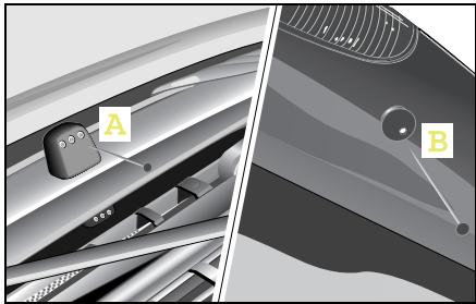
Adjusting the wiper nozzles
The wiper nozzles are located
- in the centre between the service screens (A),
- next to the third brake light on the tailgate (B).
Use a needle to adjust the spraying range of the wiper nozzles.
>Note!
The wiper nozzles are correctly adjusted if the jet of water strikes approximately the centre of the windscreen or the rear window.
Care notes
Regular care will protect your car from external influences both on the outside and in the inside and will help it to retain its value.
>Note!
You will find the care notes for your convertible sunroof top in the chapter "Variable driving enjoyment" (page 125).
>Important!
Please observe the instructions for use printed on the packaging of the cleaning agents.
smart gmbh recommends the use of smart-care products, as
they exhibit excellent cleaning capability and provide an optimum level of protection,
- the products have been specifically designed with the smart's materials in mind and
- allsmartcare products are free of dyes and fragrances.
>Note!
Allsmartcareproductsareavailable fromaqualified specialistworkshop, e.g.asmartcenter.
The following types of dirt should be removed immediately:
- Bird droppings
-Tree resins
- Dead insects etc.
>Note!
Failure to remove such dirt immediately can cause damage to the paint. These factors are environmental influences that are not covered by warranty.
Care notes
Washing the car

Accident risk!
After washing the car, the brakes may still be wet and thus their functionality impaired. Therefore, when you start off, brake lightly several times without endangering traffic.
Things you should watch out for before washing your car!
Remove caked-on grime such as
- dead insects, bird droppings and tree resins,
- oils, grease, fuel and tar.
- Do not aim the high-pressure cleaner directly at the vehicle's seals.
Insects, removing
Remove insects before you start to wash the car.
Use the smartcare insect remover spray.
After this, allow the insect remover to work itself in for a few minutes.
Rub it in lightly with a damp cloth or sponge.
Rinse off thoroughly with a generous supply of water.
Apply hard wax to the cleansed surface.
Tar, removing
Remove any tar marks before washing the car.
Apply the tar remover with a damp cloth.
After this, allow the tar remover to work itself in for a few minutes.
Rub it in lightly.
Rinse off thoroughly with a generous supply of water.
Apply hard wax to the cleansed surface.
Washing your car by hand
■ Wash your car using car shampoo concentrate and a sponge.
Rinse the car with clear water afterwards.
Rub your car down with a leather cloth.
>Important!
Do not wash the car in direct sunlight. The body panel surfaces and paint finish may be damaged.

Environment!
Wash your car at a dedicated car wash area or at a car wash facility. Washing your car in the street can cause e.g. lubricants to drain into the sewage system and harm the environment.
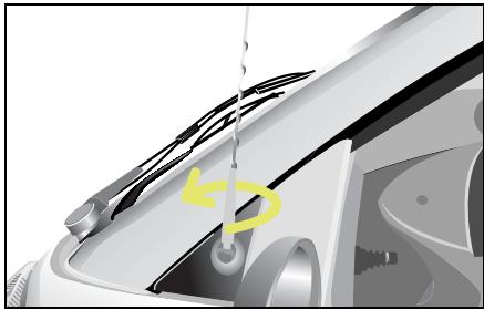
Washing your car in the car wash
Unscrew your car's antenna before driving into the car wash.
When running your car through the car wash, water droplets can run down the inside of the side windows.
Care notes
Frequency of paintwork care
The frequency with which you care for your paintwork is dependent on
- the car's degree of usage,
- where you normally park the car (e.g. in a garage or under a tree),
- the season and
- weather and environmental influences.
Paintwork damage, rectifying
You can use a touch-up paint stick to repair minimal stone-chip damage and scratches.
The smartcare touch-up paint sticks can be obtained in a qualified specialist workshop, e.g. a smart center.
>Note!
For any major paintwork damage, please contact a qualified specialist workshop, e.g. a smart center.
Exterior
Plastic body panels with clearcoat paint
Body panels with base coat and clearcoat
tridion safety cell
Repair options
Touch-up paint stick clear lacquer
smartcare two-layer touch-up paint stick set in the appropriate colour, e. g. star blue
smartcare two-layer touch-up paint stick set in the appropriate colour, e.g. silver
All care products are available as smart-care products in a qualified specialist workshop, e.g. a smart center.
| Interior | Special considerations | Light soilage | Heavy soilage | Never do the following |
| Cloth upholstery in the car | Use a clean, non-fluffy cloth | Light soap suds | Stain remover
>Important!
Use only mild soap suds for scodic grey cloth upholstery | Rub roughly, use cleaning spirits |
| Plastic parts inside the car | Use a colour-fast cloth | Damp, clean cloth, cockpit spray | Damp, clean cloth, cockpit spray | Scour, use solvent |
| Leather upholstery in the car | Use a clean, colour-fast cloth | Clean cloth with lukewarm water, leather care product | Leather care product | Use strong agents, stain remover etc. |
| Car windows | | Damp, clean cloth, microfibre cloth, glass cleaner | Microfibre cloth, glass cleaner | Strong and aggressive agents |
Care notes
All care products are available as smart-care products in a qualified specialist workshop, e.g. a smart center.
| Exterior | Special considerations | Normal soilage manual/automatic car washes | Heavily soiled, manual/automatic car washes | Never do the following |
| tridion safety cell, black | Powder coated single-coat paint finish | Car shampoo concentrate, insect remover for insect remains, polish | Car shampoo concentrate, hard wax, insect remover for insect remains, polish | Aggressive paint cleaner, machine polish, abrasive cleanser, acidic, highly alkaline agents, abrasive sponges, high-pressure or hot water cleaning equipment |
| tridion safety cell, silver | Powder coated single-coat paint finish and clearcoat |
| Highly polished plastic parts (body panels) | Body panels with base coat and clearcoat or clearcoat only |
| Wheels and wheel covers | Two-layer metallic paint (high-gloss) | Car shampoo concentrate, rim care | Car shampoo concentrate, rim care |
| Convertible soft top | Landmark fabric | Car shampoo concentrate, soft top cleaner, impregnation spray | Car shampoo concentrate, soft top cleaner, impregnation spray |
| Convertible rear window | Vinyl window | Car shampoo concentrate, glass cleanser, rear window polish | Car shampoo concentrate, glass cleanser, rear window polish | Scour, use solvent |
Contents
On-board diagnosis socket (OBD) 226
Fuses. 227
Bulbs 232
12-volt power socket 235
Breakdown set* 236
Wheel trim cap* 242
Wheel theft protection* 243
Tyres and wheels 244
Battery 252
Roll starting 259
Towing. 260
Fire extinguisher* 263
>>Communications breakdown.
If trouble looms for your car, we won't leave you on your own. We'll show you how you can quickly help your car and yourself get out of trouble. It goes without saying that qualified specialist workshops such as a smart center or smartmove Assistance are always ready to lend you a helping hand at any given time.
On-board diagnosis socket (OBD)
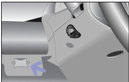
On-board diagnosis socket (OBD) The on-board diagnosis socket is located to the left of the steering wheel, in the storage tray.
Fuses
An electrical consumer has stopped functioning
The reason may be a faulty fuse. The individual circuits are protected by means of safety fuses.

Fire hazard!
Only use fuses which have been approved for smart vehicles and which have the correct amperage for the respective system. A circuit overload could otherwise cause a fire. Do not attempt to repair or bridge faulty fuses. Have the cause determined and rectified by a qualified specialist workshop, e.g. a smart center.
>Important!
Blown fuses must be replaced with equivalent fuses (recognisable by colour and amperage) that have the amperages which are recommended in the fuse assignment. Only change fuses when the vehicle is parked. Also switch off all consumers as well as the ignition.
If a newly replaced fuse blows again, have the cause of the problem determined and rectified in a qualified specialist workshop, e.g. a smart center.
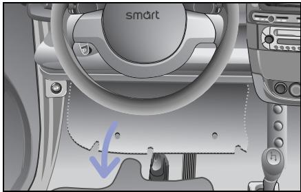
The fuse box is located on the left-hand side below the cockpit.
- Fold down the fuse box cover.
The fuse box can be seen from below.
Fuses
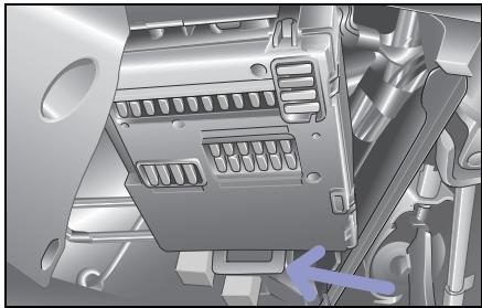
Changing a fuse
- Shut down all electrical consumers and switch the ignition off before changing a fuse.
Take the fuse box out of its holder and swing it down.
Use the fuse table (see page 230 ff) to ascertain which fuse is assigned to the failed consumer.
Remove the corresponding fuse from its holder.
Replace the defective fuse with a new one of identical amperage.
Mount the fuse box back in place.
Ensure that the lever engages again.
Fuse box, front
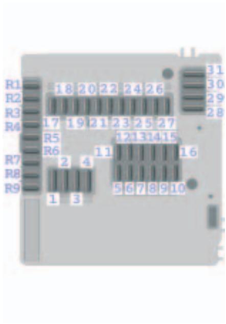
Fuse box, rear
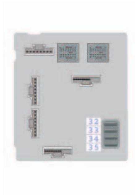
Fuses
Fuse assignment
| No. | Consumers | Amperage | Colour |
| 1 | Starter | 25 A | Neutral |
| 2 | Windscreen wipers, washer pump | 20 A | Yellow |
| 3 | Heater blower, seat heater | 20 A | Yellow |
| 4 | Power windows, l. & r. | 30 A | Green |
| 5 | Light switches, parking lights, low beam lights, high beam lights, headlight flashers, fog lamps | 7.5 A | Brown |
| 6 | Parking lights/tail lights, r., switch illumination | 7.5 A | Brown |
| 7 | Parking lights/tail lights, l. | 7.5 A | Brown |
| 8 | Engine | 20 A | Yellow |
| 9 | Engine | 10 A | Red |
| 10 | Engine (injection valves) | 15 A | Blue |
| 11 | Instrument cluster, hazard warning lights, central locking system, air conditioning system, heated seats, rear window heater, horn (steering wheel shift paddles), gearshifts from the steering wheel, on-board diagnosis socket (batt. +) | 7.5 A | Brown |
| 12 | Radio CD, interior light | 15 A | Blue |
| 13 | Front fog lamps | 15 A | Blue |
| 14 | ESP | 25 A | Neutral |
| 15 | Charge air cooling fan, air conditioner compressor | 15 A | Blue |
| 16 | Electric fuel pump | 10 A | Red |
| 17 | Rear window wiper (for fortwo coupé only) | 15 A | Blue |
| 18 | esp, airbag | 7.5 A | Brown |
| 19 | Elec. mirror adjustment, mirror heating | 7.5 A | Brown |
| 20 | Radio, CD, instrument cluster, tachometer, reversing lamp, heated seats, power steering, on-board diagnosis socket (ignition) | 15 A | Blue |
| 21 | Interior socket, cigarette lighter | 15 A | Blue |
| 22 | Low beam light, r. | 7.5 A | Brown |
| 23 | Low beam light, l. | 7.5 A | Brown |
| 24 | High beam light, r. | 7.5 A | Brown |
| 25 | Left high beam/high beam indicator light | 7.5 A | Brown |
| 26 | Brake light | 15 A | Blue |
| 27 | Engine control unit | 7.5 A | Brown |
| 28 | Rear window heater (fortwo coupé only)/coolant fan motor | 30 A | Green |
| 29 | Soft top (fortwo cabrio only), power glass sliding roof (fortwo coupé only) | 30 A | Green |
| 30 | Gearshift lever control unit | 40 A | Orange |
| 31 | Horn, central locking, rear lid remote unlocking | 30 A | Green |
| 32 | Secondary-air pump | 30 A | Green |
| 33 | Ignition | 50 A | Red |
| 34 | ESP | 50 A | Red |
| 35 | Power steering | 30 A | Green |
| R1 | Backup fuse (ignition) | - | - |
| R2 | Backup fuse (ignition) | - | - |
| R3 | Backup fuse (ignition) | - | - |
| R4 | Backup fuse (ignition) | - | - |
| R5 | Backup fuse (batt. +) | - | - |
| R6 | Backup fuse (batt. +) | - | - |
| R7 | Backup fuse (batt. +) | - | - |
| R8 | Backup fuse (batt. +) | - | - |
| R9 | Seat heating | 25 A | Neutral |
Bulbs
Bulbs Bulb replacement in a qualified specialist workshop such as a smart center
Have the following bulbs replaced only in a qualified specialist workshop such as a smart center:
- Headlights
- Front fog lamps
- Interior light at the centre console
- Side turn signal lights
Note! You should have your headlight beam setting checked regularly, or at least once a year.
Replacing the bulbs
Danger of burns! Bulbs and lamps can be very hot. You should therefore allow them to cool down before you change them. Otherwise, you could be burned if you touch them.
Before changing bulbs in your car, you should make sure of the following points:
- Switch the lights and the ignition off in order to prevent any short circuits.
- Handle the bulbs only with a clean cloth that is free of grease.
- Do not hold the bulbs by the glass.
- Do not handle the bulbs with wet or greasy fingers.
- Use only identical bulbs with the same wattage.
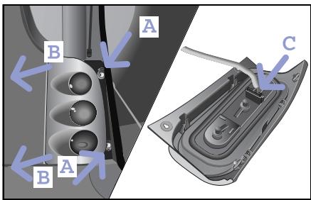
Replacing the smart fortwo coupé taillight bulbs
Each taillight consists of:
- Bulb, turn signal 12 V 21 W
- Tail lamp/brake light 12 V 21 W
- Rear fog lamp (left) 12 V 21 W
- Backup lamp (right) 12 V 21 W
Open the tailgate.
■ Unscrew the two retaining screws (A).
Press the taillight out of the apertures in the body (B).
Pull the plug connector from the bulb socket (C).
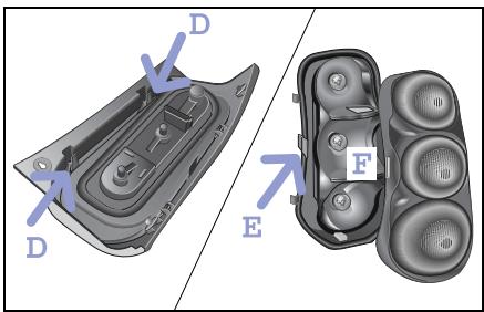
- Clip the taillight housing out of the surround and lens (D).
Remove the lens from the surround (E).
Turn the bulb anticlockwise and take it out of the holder (F).
>Note!
Installation occurs in reverse order.
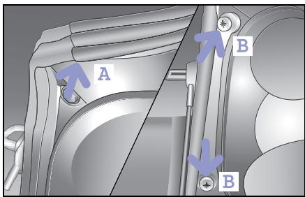
Replacing the smart fortwo cabrio taillight bulbs
Open the tailgate.
Now, fold up the rear soft top.
Pull the seal off of the body (A).
■ Unscrew the two nuts (B).
Bulbs
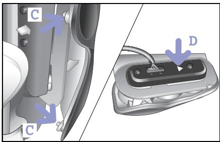
Press the taillight forward and remove the retaining lugs from the holes in the body (C).
You can now remove the taillight.
Push back the tab (D).
You can remove the bulb holder.
Remove the defective bulb.
>Note!
Installation occurs in reverse order.
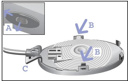
Changing the interior light at the rear
You need a 12 V 7 W bulb.
Lever the rear light out of its holder with a coin (A). To do this, position the coin from the passenger side.
Unclip and remove the surround from the lens (B).
Remove the bulb from the holder.
>Note!
Installation occurs in reverse order. When replacing the interior light, makesure that the clip (C) is located to the left.
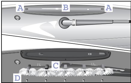
Changing the third brake light
Loosen and remove the retaining screws (A).
Remove the lens (B).
Remove the reflectors (C).
Remove the faulty bulb (D) from its holder.
>Note!
Installation occurs in reverse order.
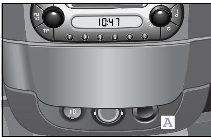
12-volt power socket
The 12-volt power socket (A) serves as a power supply for the following when the ignition is switched on:
- The cigarette lighter in conjunction with the ashtray
- The electric air pump, in conjunction with the breakdown set
- Other consumers that operate on 12 volts and a max. of 5 amperes (60 watts) and have the matching plug attached
>Note!
Do not damage the holder of the 12-volt power socket by trying to insert unsuitable plugs.
>Important!
Please observe the safety instructions given in the respective operating instructions.
Please note that
- the 12-volt power socket is only rated to handle a permanent load of 5 amperes (60 W).
- the electric air pump can be connected to the 12-volt power socket for the time it takes to inflate the tyre without any problem.
- the car battery will discharge when current is drawn.
Breakdown set*
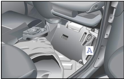
Breakdown set*
The breakdown set can be used to seal cuts of up to approx. 4 millimetres in diameter on the tyre tread.
The breakdown set (A) is located in the passenger-side footwell below the carpet.
The breakdown set comprises:
- Puncture-sealing gel bottle
-Fillertube
- Valve extractor
- Valve extractor with valve insert
- Electrically-operated pump with connector tube
- "80 km/h" and "50 mph" label
- Operating instructions
>Notes!
- Only use the tyre sealant in outside temperatures ranging from -20^ to +60^ .
- Do not remove any foreign objects such as nails or screws that have penetrated the tyre.
- Do not use the tyre sealant if the tyre has been damaged by being driven when insufficiently inflated (e.g. bumps, cuts, cracks etc. on the tyre).
- Allow escaped tyre sealant to dry, then peel it off.
- Immediately wash all painted surfaces that came into contact with the tyre sealant using a damp cloth.
- Do not allow the tyre sealant to get into your eyes!
- Do not swallow the tyre sealant!
- Allow the tyre sealant that is inside the damaged tyre to dry and dispose of together with the tyre.
- Do not use the tyre sealant after the "use by" date (see reverse of bottle)!

Danger of injury!
Do not allow the tyre sealant to
come into contact with the skin, eyes or clothing!
- If the tyre sealant comes into contact with the eyes, thoroughly rinse them immediately with clean water.
- Immediately change out of any clothes contaminated with the tyre sealant.
- If an allergic reaction occurs, consult a doctor immediately.
Danger of poisoning!
Keep the tyre sealant away from them.
- If the tyre sealant was swallowed, immediately rinse out mouth thoroughly and drink plenty of water.
- Do not induce vomiting. Consult a doctor immediately.
- Do not inhale tyre sealant fumes.
Accident risk!
Your safety is particularly at risk in the following cases, where the tyre sealant will be unable to repair the tyre:
- If there are cuts or punctures in the tyre greater than 4mm
- If the rim is damaged
- If the disc wheel is damaged
- If you have been driving on tyres with very little or no air
Do not drive any further. Consult a qualified specialist workshop which has the necessary specialist knowledge and tools to carry out the work required.
smart gmbh recommends that you visit a smart center for this. In particular, work relevant to safety or on safety-related systems must be carried out at a qualified specialist workshop.
Breakdown set*
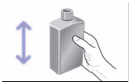
Repairing tyres with the aid of the breakdown kit
- Affix the sticker "max. 80km / h " within the driver's field of vision.
- Shake the tyre sealant bottle before use.
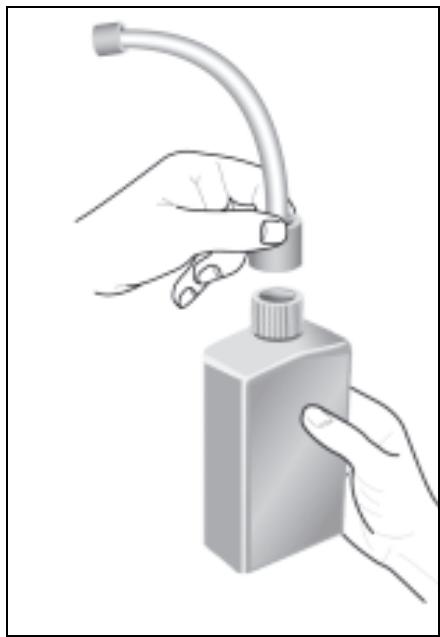
Screw the filler hose onto the bottle.
This punctures the aluminium seal.
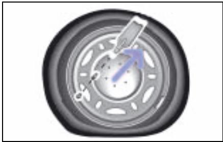
Remove the dust cap from the valve.
- Unscrew the valve insert using the enclosed valve remover.
>Note!
Take care to protect the valve insert against contamination. Should the insert be damaged, a replacement valve insert can be obtained from the bag of small parts.
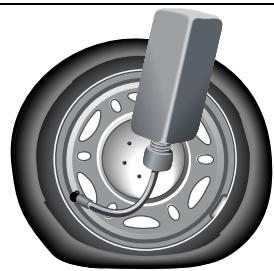
Remove the stopper from the filler hose and push the end of the hose onto the tyre valve.
Hold the bottle with the filler hose pointing downwards and squeeze it.
Press the entire contents of the bottle into the tyre.
Pull the hose off the valve and remove any residual sealant from the valve, rim and/or tyre.
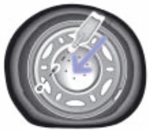
Screw the original valve insert (or the replacement one if necessary) back into the valve with the valve remover.

Fit the compressor's air hose accurately onto the valve.
Plug the power connection into the 12-volt power socket.
Inflate the tyre to at least 1.8 bar (maximum 2.5 bar).
>Note!
Do not run the electric compressor for more than six minutes. If you do so, there is a risk of overheating!
Breakdown set*
>Note!
If a pressure of 1.8 bar cannot be generated, disconnect the compressor from the wheel. Carefully drive the car 10 meters forward or backward to distribute the tyre sealant in the tyre. Inflate the tyre again.

Accident risk!
If a pressure of 1.8 bar still cannot be achieved after five minutes, the tyre is too badly damaged.
Do not drive any further. Consult a qualified specialist workshop which has the necessary specialist knowledge and tools to carry out the work required.
smart gmbh recommends that you visit a smart center for this. In particular, work relevant to safety or on safety-related systems must be carried out at a qualified specialist workshop.

Accident risk!
Do not exceed the maximum speed of 80~km / h . The "max. 80~km / h " sticker must be affixed within the driver's field of vision. The vehicle's handling characteristics may be affected.
Continue your journey immediately after removing the compressor, so that the tyre sealant is distributed evenly around the tyre's interior and can seal the damaged point.
After driving for about ten minutes, check the pressure with the gauge on the compressor.

Accident risk!
If the tyre pressure is below 1.3 bar, the tyre is too badly damaged. Do not drive any further. Consult a qualified specialist workshop which has the necessary specialist knowledge and tools to carry out the work required. smart gmbh recommends that you visit a smart center for this. In particular, work relevant to safety or on safety-related systems must be carried out at a qualified specialist workshop.
>Note!
If the pressure has fallen below 1.3 bar, do not continue your journey. If the pressure exceeds 1.3 bar, increase the tyre pressure to the level indicated in the car's operating instructions using the compressor. Carefully drive to the next qualified specialist workshop, e.g. a smart center.
>Note!
The manufacturer is unable to guarantee that all tyre punctures can be repaired with the breakdown set, in particular cuts or perforations with a diameter of more than 4mm (1/8 in) or away from the tyre's tread. The manufacturer is not liable for damage sustained through improper use of the breakdown kit.
Wheel trim cap*
Wheel trim cap*

Accident risk!
Check regularly - ideally each time you fill up with fuel - that the wheel trim caps are firmly seated on the rims. A wheel trim cap could work its way loose and endanger other road users.
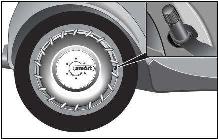
Fitting the wheel trim cap
Align the opening of the wheel trim cap with the tyre valve.
Push the wheel trim cap with both hands evenly onto the wheel rim.
Check that the wheel trim cap sits firmly on the wheel rim.
Removing a wheel trim cap
To remove a wheel trim cap, pull it carefully off the wheel rim with both hands.
Cleaning and care
The wheel trim cap can be cleaned with: - washing shampoo and a soft brush or in the car wash.
Wheel theft protection*

Accident risk!
The anti-theft wheel bolts must be retightened with a torque spanner between 100 and 500 kilometres (see "Tightening torque"). Otherwise the bolts could become loose and endanger yourself and other road users.
Caution!
Do not use impact wrenches. Store the security key in a suitable place in the car.
Caution!
For safety reasons, do not fit any hub caps or covers when fitting anti-theft devices to steel wheels.
>Note!
In the event of the security key being lost, please contact a qualified specialist workshop (e.g. a smart center), presenting the code card for your key. Keep the code card for your key in a safe place.
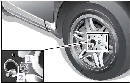
Fitting the anti-theft devices
Remove one wheel bolt from each wheel.
Turn the anti-theft wheel bolt (1) with the attached security key (2) and tighten with a torque wrench.
Tightening torque: 110 Nm
Tyres and wheels
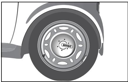
Tyres and wheels
In the interests of safety, smart gmbh recommends that you use tyres that it has specially approved for your car. These tyres have been chosen to suit control systems such as abs and esp. If you use other tyres, smart gmbh is unable to accept any responsibility for damage resulting from their use. Information on tyres is available from any qualified specialist workshop, e.g. a smart center.
If you are using tyres that have not been tested and recommended by smart gmbh, their characteristics such as road behaviour, noise and wear rate etc. could be poorer.
Dimensional deviations and a change in the way the tyres are compressed under load during operation could in addition cause them to rub against the body or axle components. This could result in damage to the tyre or vehicle.
smart gmbh neither tests nor recommends the use of retreated tyres. The preliminary stages of damage cannot always be detected on tyres that are being retreated. smart gmbh is therefore unable to guarantee driving safety with retreated tyres.

Accident risk!
Only use wheels of the dimensions stated in the vehicle registration documents. If other wheel sizes are used:
- The wheel brakes or chassis components could be damaged.
- Clearance between the wheels and tyres is no longer assured.
Modifications to the brake system and wheels and the use of spacer and brake dust rings are not permissible. In both cases the vehicle's operating approval will be nullified.
Please note in particular:
- Use only tyres and wheels of the same type and make.
- Fit only the correct type of tyre on each wheel.
- Where a car has the same size of wheel at the front and rear, only switch tyres between the front and rear axles (RF to RR; LF to LR).
- Fit new tyres on the rear wheels.
- Break in new tyres at moderate speeds for the first 100 kilometres.
-
Check tyres and wheels regularly for damage. Damaged wheels could result in a loss of pressure from and damage to the tyres.
-
Do not use tyres with an excessively low tread. Below a tread depth of
3 millimetres, grip will deteriorate sharply on wet roads. Summer tyres with a tread depth of 3 millimetres and winter tyres with a tread depth of less than 4 millimetres must therefore be replaced without fail.
- Change the tyres after no later than six years, irrespective of the level of wear. The same applies to the spare wheel.
>Note!
Store tyres in a cool, dry and preferably dark place when not fitted to the car. Protect the tyres against oil, grease and fuel. Never clean the tyres with high-pressure equipment. Your tyres could otherwise be damaged.
Operating safety and roadworthiness
Tyres are a particularly important aspect of the car's operating safety and roadworthiness. For this reason, check the tyre inflation pressure, tyre tread and tyre condition at regular intervals.
A tyre specialist shop or a qualified specialist workshop, such as a smart center, will be able to supply further information on:
- tyre load capacity (LI, load index),
speed index (maximum permitted operating speed of a tyre),
-tyreage,
- the causes and consequences of tyre wear,
- measures to take in the event of tyre damage,
- tyre types for particular regions, operating areas or operating conditions of the vehicle.
scope for converting tyres, etc.
Tyres and wheels
Tyre condition
Check tyres at regular intervals, e.g. for:
external damage,
- ageing,
- foreign bodies in the tread,
- cracks, bulges,
- one-sided or irregular tread wear.
Tyre tread
Do not undercut the minimum tread depth of 3 millimetres for summer tyres and 4 millimetres for winter tyres.
Along with increasing tyre wear, the tyres' grip and car's handling characteristics deteriorate, particularly on wet or snow-covered roads. You should therefore change tyres before they undercut the minimum tread depth.
You should measure the tread depth with a tread depth gauge, available from a qualified specialist workshop such as a smart center.
Wear indicators integrated into the edge of the tread provide an additional visual sign as to whether the tyres need to be changed or not. These indicators, however, do not form narrow, continuous patterns until the depth of the remaining tread to the base of the tread groove has reached 1.6 millimetres (1/16 in). If you can see this indicator, the tyre must be replaced without delay.

Accident risk!
Always make sure the tyre tread is adequate. Too shallow a tyre tread will reduce the tyres' grip considerably and increase the risk of aquaplaning on wet or slushy roads and at high speeds. The tyre's tread will then no longer be able to cut through the water. You could lose control of your vehicle, cause an accident and injure yourself or others.

Accident risk!
Note that cracks, bulges or external damage could cause the tyre to burst. You could lose control over your vehicle as a result, cause an accident and injure yourself or others. All tyres exhibiting such defects must be replaced without delay.
Tyres continue to age even if they are used little or not at all. The operating safety and roadworthiness of all tyres gradually decreases. You should therefore replace tyres that were manufactured more than six years ago.
The date of production is indicated in the DOT number, which is displayed on the side of every tyre. Since 2000, the last two digits denote the tyre's year of production, preceded by two digits indicating the tyre's week of production (WWYY).
Tyredamage
Tyre damage may be caused e.g. by:
- the vehicle's operating conditions,
-curbs,
- foreign bodies,
- inadequate tyre inflation pressure,
- weather and environmental factors, contact with oils, greases, fuels, etc.
Accident risk!
Driving over curbs or sharp-edged objects can cause damage to the tyre's carcass that is not externally visible. Damage to the tyre's carcass will only become evident much later and may result in tyre damage. You could lose control of your vehicle as a result and cause an accident which could injure yourself or others.
Interchanging wheels

Accident risk!
Do not interchange the front and rear wheels as they have different dimensions, e.g. rim size, wheel offset etc.
Clean the contact surface of the wheels and brake disc/inner side of the wheel each time the wheels are changed. Check the tyre inflation pressure.

Accident risk!
Never clean tyres with high-pressure equipment. This could lead to tyre damage and failure. You could consequently cause an accident or injure yourself or other persons.
Tyres and wheels
Changing a wheel

Accident risk!
Exceeding the quoted tyre load capacity and the permissible speed limit can result in tyre damage or tyre failure. You could lose control over your vehicle and cause an accident, injuring yourself or others as a result.
Only use wheels of the dimensions stated in the vehicle registration documents. Please note in particular the customer-specific approval regulations for tyres.
These regulations may specify the use of a particular tyre type for your car, or prohibit the use of certain tyre types that are permitted in other countries.
The use of a particular type of tyre may moreover be recommended for certain regions and areas of use. Information on tyres is available from a qualified specialist workshop, e.g. a smart center.

Accident risk!
Have the tightening torque checked after every wheel change at a qualified specialist workshop which has the necessary specialist knowledge and tools to carry out the work required. smart gmbh recommends that you visit a smart center for this. In particular, work relevant to safety or on safety-related systems must be carried out at a qualified specialist workshop.
The wheels could work loose if they are not tightened to a torque of 110 Nm. For safety reasons, smart gmbh recommends using only the appropriate wheel bolts approved by smart.
Tyres and wheels
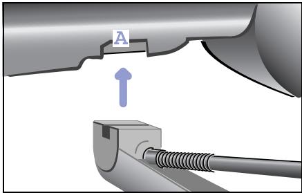
Removing a wheel
Danger of injury! Position the jack only at one of the appropriate jacking points. If you do not position the jack correctly, the vehicle can:
- Slip off the jack
- Injure you or others
- Become damaged

Danger of injury!
The jack is designed only to raise the vehicle for a short time while a wheel is being changed.
If you intend to work under the vehicle, place the vehicle on stands.
Make sure that the jack is placed on solid, non-slippery, level ground. Do not use wooden blocks or similar as jacking supports. The jack would no longer be able to achieve its load-bearing capacity due to the restricted height.
Do not start the engine at any time while the wheel is being changed. Do not lie under the vehicle when it is being supported by the jack. If you do not raise the vehicle as described, it could slip off the jack (e.g. if the engine is started or a door or tailgate is opened or closed).
Park the car on a level surface.
Apply the footbrake.
Apply the handbrake.
Move the softup gearshift control to position R.
Release the footbrake.
Switch off the engine.
Lever the wheel cap off the rim if necessary.
Use a suitable wheel wrench to slacken off the wheel bolts by turning them anticlockwise, but do not remove them yet.
Position a suitable car jack at one of the designated jacking points (A). These can be identified by impressions in the door sill area.
The contact surface of the jack support must be positioned vertically below the jacking point (A).
Tyres and wheels
Lever the car up using the jack until the wheel is off of the ground.
- Completely unscrew the wheel bolts and remove the wheel.
Fitting a new wheel

Accident risk!
Only use wheel bolts that have been designed for the wheel and the vehicle. Other bolts could work loose. Do not tighten the wheel bolts completely while the vehicle is still jacked up. The vehicle could topple off the jack.

Accident risk!
Replace damaged or corroded wheel bolts. Never oil or grease wheel bolts.
If a wheel hub thread is damaged, you must not drive the vehicle any further. Consult a qualified specialist workshop which has the necessary specialist knowledge and tools to carry out the work required.
smart gmbh recommends that you visit a smart center for this. In particular, work relevant to safety or on safety-related systems must be carried out at a qualified specialist workshop.
Only use wheel bolts that have been designed for the wheel and the vehicle.
For safety reasons, smart gmbh recommends using only the wheel bolts approved by smart. Other bolts could work loose.
Tyres and wheels
Fit the wheel in place and tighten the bolts handtight using the wheel wrench.
Lower the car and remove the jack from under it.
- Tighten the wheel bolts firmly using the wheel bolt spanner (tightening torque: 110 Nm).
>Note!
If the newly mounted wheels exhibit any imbalance, have this checked and rectified by a qualified specialist workshop, e.g. a smart center.

Accident risk!
Have the tightening torque
checked immediately after a wheel is changed. The wheels could work loose if they are not tightened to a torque of 110 Nm.
Battery
Battery
Safety notes and protective measures when handling the battery
Always observe the following safety notes and protective measures when handling the battery.
Use original smart batteries to assure a reliable fit and the correct functioning of electrical systems.

Danger of explosion!

Fire, naked flames and smoking are therefore prohibited when handling the battery. Avoid creating sparks.

Battery acid is corrosive. Avoid contact with the skin, eyes or clothing. Wear suitable clothing, especially gloves, and facial protection. Immerse acid splashes off with water. Consult a doctor if neces

Wear eye protection. Immediately rinse acid splashes off with clean water. Consult a doctor if necessary.

Keep children away.

Observe these operating instructions.
>Important!
Do not operate the vehicle without a battery fitted, otherwise its electrical equipment could be damaged.

Danger of explosion!
Do not place any metal objects on a battery. You could otherwise cause a short circuit and the battery's highly flammable gas mixture could ignite.

Danger of explosion!
If the positive terminal of the connected battery is allowed to make contact with vehicle components, there could be a short circuit which could ignite the highly explosive gas mixture generated by the battery. You and others could sustain serious injuries as a result.
- When disconnecting the battery, always disconnect first the negative terminal, then the positive terminal.
- When connecting the battery, always connect first the positive terminal, then the negative terminal.
- Do not loosen or disconnect the battery terminal clips while the engine is running.

Environment!
Do not dispose of batteries with the household rubbish. Dispose of defective batteries in an environmentally responsible manner.
Bring them to a smart center or a collection point for old batteries.
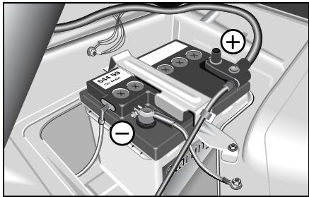
Your car's battery
Models with a petrol engine:
- 12 volts and 42 ampere hours.
- 12 volts und 61 ampere hours (cold zone).
Models with a diesel engine:
- 12 volts and 61 ampere hours.
Battery
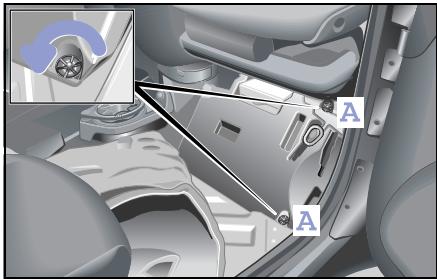
Installing and removing the battery
Make sure that
- you do not mix up the terminal clips. The battery could otherwise be destroyed.
- you never allow a wrench or other metal parts to come into contact with both battery terminals or with the positive terminal and the car body at the same time. There could otherwise be a short-circuit.
Removing the battery
Switch off the engine.
Switch off all electrical consumers.
Open the passenger door.
■ Slide the passenger seat back.
- Fold the carpet up.
Loosen the foot support's two fastening screws (A).
Remove the foot support by taking it sideways out of the car.
■ First, unscrew the negative terminal (A), then the positive terminal (B).
Remove the battery mount (C).
Remove the battery.
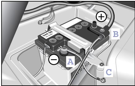
■ First, unscrew the negative terminal (A), then the positive terminal (B).
Remove the battery mount (C).
Remove the battery.
Installing the battery
Switch off all electrical consumers where appropriate.
Place the battery in the designated area.
Fasten the battery mount (C).
First fasten the positive terminal (B), then the negative terminal (A).
Mount the positive terminal cover.
Mount the foot support.
Tips on battery care
- Your car's battery requires no maintenance in normal vehicle operation (DIN 43539/T2).
However, have the battery's charge status and acid level checked at the start of the cold season by a qualified specialist workshop, e.g. a smart center.
-
The battery stoppers on the top must be opened to check the acid level. Acid must come up to MAX mark.
-
If the car is used almost exclusively for short trips, recharge the battery approximately every three months. This will preserve your vehicle's startability and prolong the battery's operating life.
- Disconnect the car's battery for extended periods of non-use and recharge approximately every six months.
- If the car is left for extended periods of time (three to four weeks) with the battery still connected, it must be re-charged.
Battery
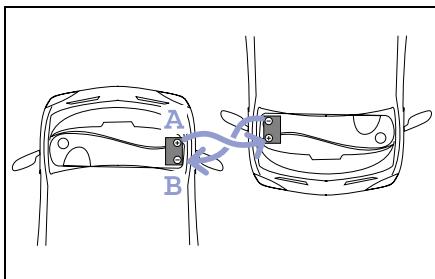
Jump starting
If your battery is flat and the car will not start, another vehicle may be able to help you start.
Start your car's engine with the aid of
- jumper cables and
- the battery of the assisting vehicle.
Observe the following instructions when doing this.

Danger of explosion!
Gases escaping from the battery during jump-starting may cause minor explosions. Avoid creating sparks. Keep naked flames away from the battery and do not smoke.
Comply with safety precautions and take protective measures when handling batteries.

Danger of injury!
There is a risk of acid burns when
jump-starting a vehicle or recharging the battery due to escaping gases.
Therefore, do not lean over the battery.
Things you need to know
Only use batteries with identically rated voltages (12 volt).
- Ensure that the capacity of the battery in the assisting vehicle is not significantly lower than that of the discharged battery.
- Use jumper cables of a suitable cross-section and insulated cable clamps; these are available from a qualified workshop, such as a smart center.
- Ensure that the vehicles do not contact each other.
- Position the jumper cables such that they cannot be caught by rotating parts in the engine compartment.
- Do not disconnect the discharged battery from the vehicle's electrical system.
Jump-start assistance
Switch off the engine of both vehicles.
Put the selector lever to N.
Switch off all electrical consumers.
Remove the battery cover.
- Connect the positive terminal (A) with the red jumper cable. Begin with your own battery.
- Connect the negative terminal of both batteries (B) with the black jumper cable. Begin with the battery of the assisting vehicle.
Let the engine of the assisting vehicle run in neutral.
- Deactivate the electronic immobiliser (see page 140).
Start your car's engine.
If the engine does not start right away, leave approx. 60 seconds between starting attempts.
If the engine will not start, call a breakdown recovery service, e.g. smartmove Assistance or a qualified specialist workshop, such as a smart center.
Removing the jumper cables
- Do not switch on electrical consumers such as the blower or the rear window heater until the engine is running.
Do not switch the lights on!
This helps reduce the danger of any sparking when removing the jumper cables.
Let the engine run 2 to 3 minutes until it runs smoothly.
- Disconnect the jumper cables from the negative terminal of both batteries (B). Begin with your own battery.
- Disconnect the jumper cables from the positive terminal of both batteries (A).
Have the battery checked by a qualified specialist workshop, e.g. a smart center.
Battery
Charging the battery

Danger of injury
Danger of explosion!
When charging the battery, deflagrations can occur due to gases escaping from the battery. Avoid creating sparks. Keep naked flames away from the battery and do not smoke.
Do not touch the battery terminal with metal objects and do not remove the battery charger's terminal clamps until the battery charger has been switched off and no further gas is being discharged by the batteries.
Only charge the battery in a well ventilated area.
There is a risk of acid burns during the charging procedure due to the gases which escape from the battery. Do not lean over the battery when it is being charged.

Danger of injury!
Never attempt to charge the installed battery. As the battery is being charged, gases can escape and generate minor explosions, which may injure you and other persons or cause damage to the paintwork or acid corrosion on the vehicle.
- Only use chargers of a correct or suitable voltage.
- Never attempt to recharge a frozen battery. Have the battery checked by a qualified specialist workshop, e.g. a smart center. The housing could be damaged.
>Note!
Disconnect the battery for rapid charging prior to using the charger.
Roll starting
Roll starting
If the starter is faulty you can try to start the car by letting it run down a steep hill.
Preparations
Apply the footbrake.
Switch on the ignition.
Move the gearshift lever to position + and hold it there.
Roll starting
■ Release the footbrake.
Push the accelerator pedal to the floor. > As the speed of the car increases the clutch is automatically engaged and the engine starts.
Release the gearshift lever.
Apply pressure to the accelerator pedal.
Towing
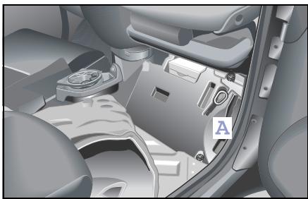
Towing
You will need a towing lug to tow another vehicle or have your vehicle towed. The towing lug (A) is located in the passenger-side footwell below the carpet. The lug always must be stored at this location in the vehicle when it is not being used.
Open the passenger door.
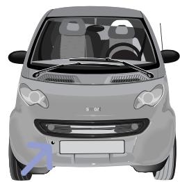
Fixing points for the towing lug
The front fixing point is for towing the vehicle.
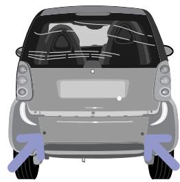
The rear fixing points are for towing other vehicles and for mounting the base rack*.
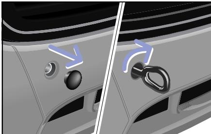
Attaching the towing lug
Take the towing lug out of the foot support in the passenger-side footwell.
Remove the cover on the vehicle.
Screw in the towing lug as far as it will go and then tighten it.
- Attach the tow rope or the tow bar to the towing lug.
Accident risk!
Have the car towed away with a tow bar if the engine cannot be started. There is no assistance for the electric power steering system* when the engine is not running. You will then need to use considerably more effort to steer and brake the car. If you are tow-starting or towing away another car, its weight must not exceed the permissible gross vehicle weight of your car. Only tow the vehicle short distances.
Towing
Switch on the ignition.
Apply the footbrake.
Move the gearshift lever to position N. >N appears in the display.
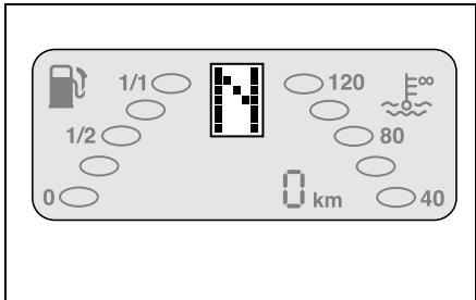
>Important!
The vehicle may only be towed when
- the gearshift lever is in position N ,
- the display shows N ,
- you are certain that no gear is engaged. This is especially the case when the battery is completely depleted, for example. Towing now can begin under consideration of the following notes.
Towing
> Towing notes!
- Only people with a certain amount of experience should tow.
- The ignition must be switched on.
- If the car is being towed, the gearshift lever must be set to position N .
- Ideally, you should have your car towed by a vehicle from a qualified specialist workshop, such as a smart center.
- Observe the national statutory regulations concerning the towing of vehicles.
-
The maximum towing speed should not exceed 50km / h (approx. 30 mph).
-
The maximum towing distance should not exceed 50km (approx. 30 miles).
- Do not tow the vehicle long distances. If you want to transport the vehicle long distances, you must use a trailer.
- When towing the car it is preferable to use a tow bar. If a tow rope is to be used, elastic polyamide ropes or polyamide belts should be used.
- The tow rope must never be attached to the base rack*!
- The towing lugs on both vehicles involved in the towing process must be on the same side.
-
The car should only be towed or tow another vehicle by means of the towing lug.
-
The towed vehicle may not be heavier than the towing vehicle.
- For safety reasons, recovery or lashing down of the car by means of the towing lug is not allowed. Failure to observe this could result in the towing lug being ripped out of its mounting and people being injured!
- Towing the car with a base carrier* mounted is not permissible.
- The vehicle must not be towed by the base carrier*!
Fire extinguisher*
Danger of injury! Ensure that the fire extinguisher is always securely fastened. Vehicle occupants could otherwise be injured by the fire extinguisher being thrown around in the vehicle in the event of: - Severe braking - A change of direction - An accident
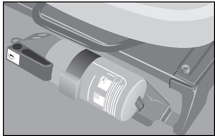
You should be aware of the following:
You should read the operating instructions before using the fire extinguisher to ensure that you can use it properly and safely at any given time.
You should have your fire extinguisher regularly checked, i.e. every 2 years.
Contents
Information signs (example: left-hand drive version) 266
Model plate 267
Technical data. 268
Homologation numbers 278
Official homologation 279
>>Data transfer.
Now, to finish off, you should take another few minutes to go through the car's technical data and soak them in. Have fun in doing so.
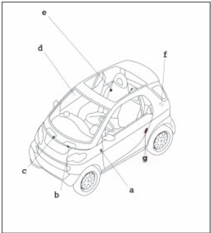
a Service label
b Coolant warning label
c Wiper mechanism warning label
Airbag information signs (sun visor/roof rail)
e Refuelling sign/tyre pressure sign
f Model plate with vehicle ident. no.
gsmartmove Assistance

Danger of injury!
Various warning stickers are affixed to your vehicle. Their purpose is to draw your attention, and the attention of others, to various dangers. Therefore, do not remove any warning stickers unless the sticker clearly states that you may do so. If you remove the warning stickers, you or others could be injured by failing to recognise certain dangers.
Made in France EBIEAF
Typ: MC 01
PZ: 7

1.2%
SMART GMBH
WME4503321J000040
-990kg
1-427kg
2-610kg

Model plate
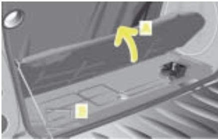
Vehicle identification number (VIN)
The vehicle identification number (B) can be found on the floor plate under the carpet (A) in the luggage compartment.
Technical data
Technical data
The technical data are valid for all standard equipped vehicles.
smart gmbh recommends that you use original smart parts and accessories.
| Engine specifications | Diesel engines | Petrol engines |
| fortwo coupé/fortwo cabrio | fortwo coupé/fortwo cabrio | fortwo coupé from BRABUS/fortwo cabrio from BRABUS |
| Rated output (kW) | 30 | 37 | 45 | 55 |
| At engine speed (rpm) | 4,200 | 5,250 | 5,250 | 5,250 |
| Nominal torque (Nm) | 100 | 80 | 95 | 110 |
| At engine speed (rpm) | 1,800-2,800 | 1,800-4,000 | 2,000-4,000 | 2,500-4,500 |
| Number of cylinders | 3 | 3 | 3 | 3 |
| Valves per cylinder | 2 | 2 | 2 | 2 |
| Spark plugs per cylinder | - | 2 | 2 | 2 |
| Total displacement (cm³) | 799 | 698 | 698 | 698 |
| Engine weight acc. to DIN 70020 A (kg) | 69 | 60 | 60 | 59 |
| Maximum climbing capacity at permissible gross vehicle weight | 20% | 20% | 20% | 20% |
Technical data
Fuel consumption in accordance with EC Directive 1999/100/EC
The following data were evaluated in accordance with the EC Directive (1999/ 100/EC). All data are valid for basic version vehicles with catalytic converter.
In practice, fuel consumption may be higher than the values determined and cited in the EC guidelines (1999/100/EC), as in everyday use different operating conditions may prevail, such as individual driving styles, additional equipment, different road surfaces and weather conditions.
The fuel consumption values given by the EC Directive (1999/100/EC) serve solely as a means of comparison in certain given conditions.
Any qualified specialist workshop such as a smart center will be able to provide further details.
Refer to the COC papers (EC-CERTIFICATE OF CONFORMITY) for the currently applicable fuel consumption ratings.
These papers are handed to you at the point of vehicle delivery.
| Fuel consumption in accordance with 1999/100/EC | Diesel engine | Petrol engines |
| fortwo coupé/fortwo cabrio | fortwo coupé/fortwo cabrio | fortwo coupé from BRABUS/fortwo cabrio from BRABUS |
| 30 kW | 37 kW | 45 kW | 55 kW |
| softtip | softtip | softtip | softtouch |
| Inner urban (ltrs./100 km) | 4.5 | 6.0 | 6.0 | 6.5 |
| Extra urban (ltrs./100 km) | 3.6 | 4.0 | 4.0 | 4.6 |
| Combined (ltrs./100 km) | 3.8 | 4.7 | 4.7 | 5.3 |
| Driving range (km) | 579 | 688 | 688 | 611 |
| Emissions standard | EU4 | EU4 | EU4 | EU4 |
| CO2 emissions (g/km) | 101 | 113 | 113 | 127 |
Technical data
| Acceleration/elasticity Maximum speed | Diesel engine | Petrol engines |
| fortwo coupé/fortwo cabrio | fortwo coupé/fortwo cabrio | fortwo coupé from BRABUS/fortwo cabrio from BRABUS |
| 30 kW | 37 kW | 45 kW | 55 kW |
| | | | |
| 0 to 100 km/h (s) | 19.8 | 18.3 | 15.5 | 12.3 |
| 60 to 100 km/h (s) in 5th gear | 13.2 | 14.7 | 11.8 | - |
| Top speed, electronically governed (km/h) | 135 | 135 | 135 | 150 |
Technical data
Wheels and tyres
>Notes on wheels and tyres!
- Use only wheels and tyres approved by smart gmbh.
This way you ensure that your car will handle optimally, which in turn guarantees the driving safety of your vehicle.
- Change over to winter tyres at an early date, preferably in the autumn.
- The vehicle operating approval status is rendered null and void if other wheel/ tyre combinations are used.
- Replace worn tyres in good time.
Every qualified specialist workshop (e.g. a smart center) will be glad to provide you with details and information concerning the wheels and tyres recommended for your smart.
| Petrol engines | fortwo coupé/fortwo cabrio | fortwo coupé from BRABUS/fortwo cabrio from BRABUS |
| Tyres, front | 145/65 R15 | 175/55 R15* | 175/50 R16* | 175/50 R16 | 175/50 R16 |
| Tyres, rear | 175/55 R15 | 195/50 R15* | 205/45 R16* | 205/45 R16 | 225/35 R17 |
| Wheels, front | 4 Jx15 ET 27 | 5Jx15 ET 27* | 5.5Jx16 ET 30* | 5.5 Jx16 ET 30 | 5.5 Jx16 ET 30 |
| Wheels, rear | 5.5 Jx15 ET -1 | 6.5Jx15 ET -1* | 6.5Jx16 ET -3* | 6.5 Jx16 ET -3 | 8Jx17 ET -15 |
| Diesel engine | fortwo coupé/fortwo cabrio |
| Tyres, front | 145/65 R15 | 175/55 R15* |
| Tyres, rear | 175/55 R15 | 195/50 R15* |
| Wheels, front | 4 Jx15 ET 27 | 5Jx15 ET 27* |
| Wheels, rear | 5.5 Jx15 ET -1 | 6.5Jx15 ET -1* |
Technical data
>Note!
Freedom of motion can only be guaranteed if the manufacturer's recommended wheels and tyres are used. Other wheel and tyre sizes may damage the braking system.
>Note!
If wide tyres are fitted on vehicles equipped with a diesel engine, the qualifying conditions for a 3-litre car will not be satisfied. In this case, the car's exemption from road tax will be nullified.
>Note!
To maintain sufficient clearance between wide tyres fitted at the front and the vehicle body, the technique used to fix the front body panel has to be modified. The professional work can be performed by your qualified specialist workshop (e.g. a smart center).
To ensure that the rear wheels are shielded as required by law, a modified fixing technique is likewise used on the fortwo cabrio. On the fortwo coupé, special black trim elements are fitted on the wheel arches.
Technical data
Snow chains*
Only the original smart accessory snow chains (part-no. 000 1792 V001) are approved for use on the smart.

Accident risk!
When fitting or removing snow chains, always park your car on a level surface and switch the engine off. The vehicle could otherwise slide and injure yourself or other road users.

Danger of injury!
When fitting and removing snow chains, ensure that you and your vehicle are at a safe distance from moving traffic. Not doing so could endanger other road users or even lead to you being injured by the vehicles behind you.

Accident risk!
The car's handling changes when driving with snow chains on any kind of road surface. You should therefore always adapt your driving style to suit the current road and weather conditions.

Accident risk!
Do not forget to retighten the snow chains. Otherwise they may work their way loose from the tyres.

Accident risk!
Only use original smart snow chains. Otherwise there is an accident risk!
>Important!
- Snow chains for the smartfortwo from BRABUS are only permitted to be used on 175/55 R15 winter tyres.
- Only fit snow chains on the rear tyres of your vehicle.
- The use of snow chains is not permitted on the wide tyres available as an optional extra.
>Note!
If other make snow chains are used:
- the vehicle operating approval status is rendered null and void,
- the car could sustain damage,
- handling can be greatly impaired.
Technical data
| Weights | All fortwo coupés including the fortwo coupé from BRABUS | All fortwo cabrios including the fortwo cabrio from BRABUS |
| Curb weight1 (kg) | 805 | 815 |
| Load capacity (kg) | 260 | 250 |
| of which maximum load in the luggage compartment (kg) | 50 | 50 |
| Permissible gross vehicle weight (kg) | 990 | 990 |
- Curb weight (acc. to 92/21/EEC) including driver (75 kg) and all operating fluids (tank 90 % full). Optional extras will increase the curb weight; as a result the payload is reduced.
| Loads | fortwo coupé/fortwo cabrio
fortwo coupé from BRABUS/fortwo cabrio from BRABUS |
| Maximum permissible axle weight, front axle (kg) | 427 |
| Maximum permissible axle weight, rear axle (kg) | 610 |
| Maximum permissible roof load | None |

Accident risk!
Do not load the roof of the car and
do not mount a roof rack!
This may significantly impair driving dynamics and lead to accidents.
Vehicle dimensions
| Length (mm) | 2,500 |
| Width (mm) | 1,515 |
| Height (mm) | 1,549 |
| Wheelbase (mm) | 1,812 |
| Tread width, front/rear (mm) | 1,272/1,354 |
| Luggage compartment, rear (ltrs.) | 150-568 |
| Turning circle, m (ft/in) | 8.70 |
| Refuelling | Diesel engine | Petrol engines |
| Fuel tank for all vehicles | fortwo coupé/
fortwo cabrio | fortwo coupé/
fortwo cabrio | fortwo coupé from BRABUS/
fortwo cabrio from BRABUS |
| Capacity, (ltrs.) | 22 | 33 | 33 |
| of which reserve capacity (ltrs.) | 5 | 5 | 5 |
| Fuel | fortwo coupé/
fortwo cabrio | fortwo coupé/
fortwo cabrio | fortwo coupé from BRABUS/
fortwo cabrio from BRABUS |
| Diesel fuel, EN 590 | Unleaded petrol
Super, EN 228,
at least 95 RON/85 MON | Premium Plus unleaded
petrol, EN 228,
at least 981RON/88 MON |
1 The 55 kW petrol engine is designed to run on unleaded fuel with a minimum grade of 98 RON/88 MON. In countries where no such petrol is available, you can refuel with 95 RON/85 MON. This, however, can reduce engine output and increase fuel consumption.
Technical data
| Fill levels | Diesel engines | Petrol engines |
| Coolant system | | |
| Coolant capacity (ltrs.) | 4.5 | 4.2 |
| Anti-corrosion agent/anti-freeze (ltrs.) | 2.25 | 2.1 |
| Windscreen washer system | | |
| Total fluid capacity (ltrs.) | 3.0 | 3.0 |
| Tyre inflation pressure (summer and winter) | | |
| 135/70 R15 front - 175/55 R15 rear (bar) | 2.0 | 2.0 |
| 145/65 R15 front - 175/55 R15 rear (bar) | 2.0 | 2.0 |
| 175/55 R15 front - 195/50 R15 rear (bar) | 2.0 | 2.0 |
| 175/50 R16 front - 205/45 R16 rear (bar) | - | 1.8/2.3 |
| 175/50 R16 front - 225/35 R17 rear (bar) | - | 1.8/2.3 |
| Engine oil | Diesel engine | Petrol engines |
| Change quantity (ltrs.) | approx. 2.7 | approx. 3.1 |
Technical data
Retrofitted electrical/electronic equipment
Retrofitting electrical or electronic equipment which may influence the driver's control over the vehicle require a type approval certificate and must be designated by means of an e symbol.
The installation of mobile phones and data transmission devices which comply with the maximum transmitting power listed below will receive the approval of the smart gmbh company if the installation is done by skilled technician and a non-reflectance aerial is used.
>Note!
If electrical/electronic devices that do not comply with the aforementioned installation specifications are fitted, the vehicle's operating approval may be rendered null and void (EU Directive 95/54/ EC).
| Frequency range (band) | Max. transmission power (watts) |
| Short wave (<50 MHz) | 100 |
| Wavelength 2 m | 50 |
| Wavelength 0.7 m | 35 |
| Wavelength 0.25 m = D + E networks | 10 |
Homologation numbers
Homologation numbers (for radio wave-based remote control)
| Country | Country code | Homologation number |
| Germany | D | G133416J |
| Austria | A | CEPT LPD D |
| Belgium | B | RTT/D/X1556 |
| Denmark | DK | CEPT/LPD/DK/9717 |
| Spain | E | E 02 98 00 74 |
| France | F | 97-0325-PPL0 |
| Italy | I | DGPGF/4/2/03/338965/FO/00171/21/01/98 |
| Luxembourg | L | L 2432/10325-01H |
| Netherlands | NL | CEPT LPD D |
| Portugal | P | ICP-069TC-97 |
| Sweden | S | Approved by National Post and Telecom Agency Ue970133 |
| Switzerland | CH | BAKOM 97.0885.K.P |
Official homologation

Official homologation
Symbols for the homologation
Germany
France
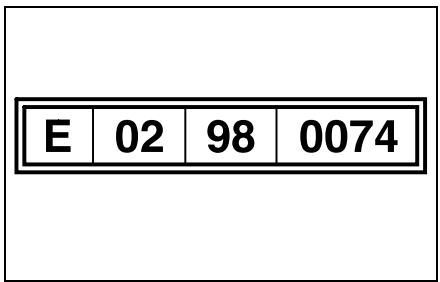
Spain
Key word index.
Key word index
A
abs 163
Indicator lamp 36
Malfunction 164
Acceleration 270
Air conditioning plus* 102
Air seat 134
Airbags 166
Front-pessenger 169
Indicator lamp 39
Side airbags. 166
Air-recirculation mode 99
Anti-lock braking system, see "abs"
Ashtray 177
Automated shifting (softouch)* 138
Automatic car wash. 221
auto-relock function 12
AUX jack* 88
Auxiliary heater* 98
B
Baby carrier* 134
Base rack* 198
Battery. 252
Charging 258
Indicator lamp 41
Installation 254
Key 15
Removal. 254
Belt force limiters 29
Belt guide 21
Belt height adjustment. 28
Belt tensioners. 29
Bicycle rack* 198
Booster cushion* 134
Boot 183
Boot tub* 186
Brake assistant 162
Brake fluid. 214
Brake pad display 162
Brakes, see "Brake system"
Braking system
Footbrake. 161
Handbrake. 160
Indicator lamp. 37
Malfunction. 164
Breakdown set* 236
Breaking in. 139
Bulbs
Changing 232
Front. 232
Rear. 233
C
Car cover* 110
Care
Automatic car wash. 221
High-pressure cleaners. 220
Sunroof top/rear soft top. 125
Vehicle. 219
Carving Kit* 198
Cassette box 80
CD box* 77
CD changer* 76
Central locking 14
Centre console,
lower 55
upper 51
Changing a wheel, see "Flat tyre"
Child restraint system*
Air seat 134
Baby carrier* 134
Basisfix 134
Booster cushion* 134
Quick coupling* 134
Recommendation. 134
Children
Automatic child seat recognition.....132
In the vehicle. 131
Restraint system* 130
Cigarette lighter 235
Cleaning, see "Care"
Clock, see "Cockpit clock"
COC documents. 269
Cockpit 31
Cockpit clock* 52
Combination filter* 102
Coming home function* 59
Consumption 269
Control lever 33
All sections marked with the * symbol refer to either factory-fitted optional extras or original smart accessories.
Key word index
Coolant 276
Checking the level. 212
Display 44
Temperature display 47
Cruise control* 154
D
Daily trip odometer 48
Daytime driving lights* 60
De-icing the windows 101
Demisting. 101
Diesel, see "Fuel"
Dimensions. 275
Dipped-beam headlamps
Driving abroad 58
Switching on/off. 58
Dirt tub* 186
Display 44
Lighting 44
Divider*
cabrio 195
coupe 193
Door handle 14
Door locking system
Indicator lamp 12
Door pocket net* 181
Drinks holder* 178
drive lock function* 13
Driving abroad. 58
Driving off. 143
Driving tips 152
Catalytic converter. 151
esp. 165
Winter. 149
E
Electrical/electronic equipment
Retrofitting 277
Electronic immobiliser. 140
Electronic Stability Program, see "esp" e-mark. 277
Emergency release 15
Engine Starting 141
Switching off. 147
Technical data. 268
Engine compartment 207
Engine oil 276
Capacity 276
Checking the oil level. 206
Oil grades. 209
Topping up 208
esp. 165
Driving tips 165
Indicator lamp. 38
F
Fill levels. 276
Fire extinguisher* 263
First aid kit* 186
Flat tyre 248
Floor mats* 137
Footbrake 161
Fresh air mode 99
Front bulbs 232
Front fog lamps* 63
Frost warning* 49
Display 44
Fuel 204
Consumption 269
Minimum quality. 275
Fuel filler flap. 205
Fuse box. 227
Fuses. 227
G
Gear indicator 46
Gearshift lever 138
Console 56
Gearshifts
Automated shifting (softouch)* 138
Malfunction 46
Manual shifting (softip) 138
Gearshifts from the steering wheel*... 138
Key word index
H
Handbrake. 160
Hands-free system* 86
Hazard warning lamps 66
Headlamp flasher 66
Headlamp range control. 61
Heater 96
Air distribution. 97
Air nozzles 96
Air-recirculation mode 99
Auxiliary heater* 98
Blower. 96
De-icing the windows 101
Fresh air mode 99
Heater booster 98
Outside mirrors* 108
Rear window. 107
Seat heater* 109
Temperature. 98
Heater booster 98
Indicator lamp 42
High-pressure cleaners. 126, 220
Homologation numbers 278
Horn 66
I
Indicator lamp
abs. 36, 164
Airbags. 39, 171
Battery 41
Braking system. 37, 164
Engine check. 43
esp. 38
Heater booster. 42
Main-beam headlamps 37
Oil pressure 41
Overview. 34
Preheating. 42
Rear fog lamp. 38
Turn signals 41
Information signs. 266
Instrument cluster 34
Display. 44
Indicator lamp. 34
Interior lighting 62
Interval wiping. 105
ipod* .87
J
Jump-starting
Jump-starting 256
Roll starting 259
K
Key 10
Battery. 15
Kickdown. 146
L
Lighting 58
Lights
Coming home function* 59
Daytime driving lights* 60
Dipped-beam headlamps 58
Front fog lamps* 63
Headlamp flasher. 66
Headlamp range control. 61
Interior lighting 62
Main-beam headlamps. 59
Rear fog lamp 64
Side lamps. 58
Load capacity 200
Loading guidelines 199
Locking button. 15
Locking in an emergency. 14
Luggage compartment. 183
Luggage compartment cover* 188
Luggage net. 186
Luggage net bag* 190
Luggage wedge* 187
All sections marked with the * symbol refer to either factory-fitted optional extras or original smart accessories.
Key word index
M
Main-beam headlamps Indicator lamp 37 Switching on/off. 59
Malfunction abs system 164 Braking system 164 Soft top system 123
Manual shifting (softip) 138
Maximum permissible gross vehicle weight 274
Maximum speed 270
Mileage 48
Mirrors
Driver sun visor* 91
inside 23
outside 22
Mobile phone
Hands-free system 86
Telephone console 83
Model plate 267
Multifunction box* 197
Multi-function display 48
N
Navigation system* 72
0
Oil, see "Engine oil"
On-board diagnosis socket 226
Outside mirror heaters* 108
Outside mirrors adjusting 22
Note 202
Outside temperature display* 48 Adjusting. 103
P
Parking 147
Passenger airbag. 169
Passenger seat, folding down. 20
Performance. 270
Petrol, see "Fuel"
Power glass sliding roof 93
Power steering 261
Power windows 24
R
Radio smart radio five*. 71 smart radio one*. 69 smart radio three*. 70
Rear bulbs. 233
Rear fog lamp. 64
Indicator lamp. 38
Rear rack* 198
Rear soft top. 113
Cleaning. 126
Display 114
Malfunction. 123
Notes. 122
Rear window Cleaning. 127
Rear window heater 107
Rear window wiper. 105
Rear-view mirror adjusting. 23
Refuelling 204
Residual litres display. 45
Remote control Changing the battery 16
Infrared remote control* 10 Radio remote control. 10
Residual litres display Instrument cluster 48 Notes. 45
Restraint system
Airbags 166
Belt force limiters 29
Belt tensioners 29
Children* 130
Indicator lamp 39
Malfunction 171
Seat belt. 25
Reversing the car. 144
Roll starting.. 259
Key word index
S
Seat
Folding down the passenger seat.....20
Height adjustment 18
Longitudinal adjustment. 18
Seat belt. 25
Height adjustment 28
Seat heater* 109
Service interval display 50
Display 44
Service screen. 211
Sideairbags 166
Side lamps. 58
Side rails Mounting 117
Removing 115
Side windows 24
Ski holder* 198
smart sound package* 88
smartmove Assistance 266
Snow chains* 273
Socket 235
Softtop system Faults. 123
Mounting the side rails 117
Notes. 122
Rear soft top. 113
Removing the side rails. 115
Sunroof top. 112
softip. 145
softtouch 146
sound package* 88
Speed limiter* 157
Speedometer 34
Storage bag* in the front passenger footwell. 182
Storage compartment* under driver seat. 175
Summer tyres 245
Sun visors. 90
Sunroof top. 112
Cleaning 126
Malfunction. 123
Notes 122
Sunroof visor* 92
T
Tachometer* 53
Tailgate cabrio. 185
coupe. 183
Tank capacity 275
Display. 45
Technical data Acceleration. 270
Coolant 276
Fuel consumption 269
Maximum speed 270
Vehicle dimensions 275
Vehicle weight. 274
Telephone console* 83
Temperature
Adjusting 98
Display, outside* 48
Tightening torque. 251
Towing. 260
Towing eye 260
Transport (vehicle) 262
Trays
Coin slots. 174
Door pocket net* 181
Drinks holder* 178
Luggage net. 186
Luggage net bag* 190
Storage bag* in the front passenger footwell. 182
Trip odometer. 48
Turn signals 65
Indicator lamp 41
Tyre inflation pressure 215
Checking 217
Table 276
Tyre pressure,
see "Tyre inflation pressure"
Tyres. 244
Damage 247
Fill pressure 215
Summer 245
Technical data 271
Tightening torque 251
Tread depth. 246
Winter 245
U
Universal hands-free system* 86
Unladen weight 274
V
Vehicle
Breaking in 139
Care 219
identification number (VIN) 267
Locking in an emergency 14, 15
Locking (auto relock function) 12
Locking (central locking switch) 14
Locking (drive lock function*) 13
Towing. 260
Transporting 262
Unlocking in an emergency 15
Unlocking (door handle) 14
Unlocking (remote control) 11, 12
Vehicle dimensions 275
Vehicle electronics. 277
Vehicle identification number (VIN)....267
Vehicle weight. 274
Ventilation
Air distribution. 97
Air nozzles 96
Blower. 96
W
Warning triangle 186
Warning waistcoat* 186
Washer fluid 213
Washing the car. 221
Wheel theft protection* 243
Wheel trim cap* 242
Wheels 244
Interchanging 247
Technical data. 271
Wind and sunroof visor* 92
Windblocker* 120
Windscreen washer system. 105
Capacity 276
Topping up 213
Windscreen wipers. 105
Adjusting the wiper nozzles 218
Replacing the wiper blades 218
Wipe and wash functions. 105
Winter driving 149
Winter tyres 245
Wiper blades. 218
Wiper control*, automatic. 106
Wiper nozzles 218
Publisher and copyright
smart gmbh
Concept and execution
cognitas. GmbH
Layout and typesetting
cognitas. GmbH
Translation
indubo translation solutions
GmbH & Co. KG
Print
Sommer Corporate Media