
K10N750SLI-110DB - Carte mère ASROCK - Notice d'utilisation et mode d'emploi gratuit
Retrouvez gratuitement la notice de l'appareil K10N750SLI-110DB ASROCK au format PDF.

| Type de produit | Carte mère ATX |
| Dimensions | 30.5 cm x 22.4 cm (12.0 po x 8.8 po) |
| Socket processeur | Socket AM2+ / AM2 |
| Processeurs compatibles | AMD Phenom FX, Phenom, Athlon 64 FX, Athlon 64 X2, Athlon X2 Dual-Core, Athlon 64, Sempron |
| Chipset | NVIDIA nForce 750a SLI |
| Mémoire | 4 x DDR2 DIMM, jusqu'à 8 Go, DDR2 1066/800/667/533 non-ECC |
| Slots d'extension | 2 x PCI Express 2.0 x16 (vert x16, bleu x8), 1 x PCIe x1, 3 x PCI |
| Stockage | 6 x SATA II 3.0 Gb/s (RAID 0, 1, 0+1, JBOD, 5), 1 x eSATA II, 1 x ATA133 IDE, 1 x FDD |
| Audio | HD Audio 7.1 canaux, codec ALC890, DAC 110 dB |
| Réseau | Gigabit Ethernet Realtek RTL8211B |
| Ports USB | 6 x USB 2.0 en panneau arrière, 2 x en-têtes USB 2.0 (4 ports supplémentaires) |
| Ports IEEE 1394 | 1 en panneau arrière, 1 en-tête |
| Alimentation requise | Connecteur ATX 24 broches, connecteur ATX 12V 8 broches |
| Technologies supportées | NVIDIA SLI, Hybrid SLI, AMD Cool'n'Quiet, Untied Overclocking |
| Form factor | ATX |
| BIOS | AMI 8 Mo, support Plug and Play, ACPI 1.1 |
| Systèmes d'exploitation | Windows XP / XP Media Center / XP 64-bit / Vista / Vista 64-bit |
| Entretien et nettoyage | Débrancher l'alimentation avant nettoyage. Utiliser un chiffon sec et antistatique. Éviter l'humidité. |
| Sécurité | Utiliser un bracelet antistatique. Ne pas toucher les composants sous tension. Débrancher avant toute manipulation. |
FOIRE AUX QUESTIONS - K10N750SLI-110DB ASROCK
Questions des utilisateurs sur K10N750SLI-110DB ASROCK
0 question sur cet appareil. Repondez a celles que vous connaissez ou posez la votre.
Poser une nouvelle question sur cet appareil
Téléchargez la notice de votre Carte mère au format PDF gratuitement ! Retrouvez votre notice K10N750SLI-110DB - ASROCK et reprennez votre appareil électronique en main. Sur cette page sont publiés tous les documents nécessaires à l'utilisation de votre appareil K10N750SLI-110DB de la marque ASROCK.
MODE D'EMPLOI K10N750SLI-110DB ASROCK
ASRock
K10N750SLI- 110dB
User Manual
Version 1.0
Published March 2008
Copyright©2008 ASRock INC. All rights reserved.
Copyright Notice:
No part of this manual may be reproduced, transcribed, transmitted, or translated in any language, in any form or by any means, except duplication of documentation by the purchaser for backup purpose, without written consent of ASRock Inc.
Products and corporate names appearing in this manual may or may not be registered trademarks or copyrights of their respective companies, and are used only for identification or explanation and to the owners' benefit, without intent to infringe.
Disclaimer:
Specifications and information contained in this manual are furnished for informational use only and subject to change without notice, and should not be constructed as a commitment by ASRock. ASRock assumes no responsibility for any errors or omissions that may appear in this manual.
With respect to the contents of this manual, ASRock does not provide warranty of any kind, either expressed or implied, including but not limited to the implied warranties or conditions of merchantability or fitness for a particular purpose.
In no event shall ASRock, its directors, officers, employees, or agents be liable for any indirect, special, incidental, or consequential damages (including damages for loss of profits, loss of business, loss of data, interruption of business and the like), even if ASRock has been advised of the possibility of such damages arising from any defect or error in the manual or product.

This device complies with Part 15 of the FCC Rules. Operation is subject to the following two conditions:
(1) this device may not cause harmful interference, and
(2) this device must accept any interference received, including interference that may cause undesired operation.
CALIFORNIA, USA ONLY
The Lithium battery adopted on this motherboard contains Perchlorate, a toxic substance controlled in Perchlorate Best Management Practices (BMP) regulations passed by the California Legislature. When you discard the Lithium battery in California, USA, please follow the related regulations in advance.
"Perchlorate Material-special handling may apply, see
www.dtsc.ca.gov/hazardouswaste/perchlorate"
ASRock Website: http://www.asrock.com
Contents
1. Introduction 5
1.1 Package Contents 5
1.2 Specifications 6
1.3 Minimum Hardware Requirement Table for Windows® Vista™ Premium 2008 and Basic Logo
1.4 Supported PCI Express VGA Card List for SLI^TM Mode 11
1.5 Motherboard Layout 12
1.6 ASRock WiFi_SPDIF I/O 13
2.Installation 14
Pre-installation Precautions 14
2.1 CPU Installation 15
2.2 Installation of CPU Fan and Heatsink 15
2.3 Installation of Memory Modules (DIMM) 16
2.4 Expansion Slots (PCI and PCI Express slots) 18
2.5 SLITMOperation Guide 20
2.6 Jumpers Setup 25
2.7 Onboard Headers and Connectors 26
2.8 HDMI_SPDIF Header Connection Guide 32
2.9 eSATAI lIInterface Introduction 33
2.10 SATAI Hard Disk Setup Guide 36
2.11 Serial ATA (SATA) / Serial ATAII (SATAII) Hard Disks Installation 37
2.12 Hot Plug and Hot Swap Functions for SATA / SATAII HDDs and eSATAII Devices 38
2.13 SATA/SATAI HDD Hot Plug Feature and Operation Guide 39
2.14 Driver Installation Guide 41
2.15 Installing Windows XP / XP 64-bit / Vista™ / Vista™ 64-bit Without RAID Functions 41
2.15.1 Installing Windows XP / XP 64-bit Without RAID Functions 41
2.15.2 Installing Windows® Vista™ / Vista™ 64-bit Without RAID Functions 42
2.16 Installing Windows XP / XP 64-bit / Vista™ / Vista™ 64-bit With RAID Functions 43
2.16.1 Installing Windows XP / XP 64-bit With RAID Functions 43
2.16.2 Installing Windows Vista™ / Vista™ 64-bit With RAID Functions 44
2.17 Untied Overclocking Technology 45
3.BIOS SETUP UTILITY 46
3.1 Introduction 46
3.1.1 BIOS Menu Bar 46
3.1.2 Navigation Keys 47
3.2 Main Screen 47
3.3 Advanced Screen 48
3.3.1 CPU Configuration 48
3.3.2 Chipset Configuration 53
3.3.3 ACPI Configuration 55
3.3.4 IDE Configuration 56
3.3.5 PCIPnP Configuration 58
3.3.6 Floppy Configuration 59
3.3.7 Super IO Configuration 59
3.3.8 USB Configuration 60
3.4 Hardware Health Event Monitoring Screen 61
3.5 Boot Screen 62
3.5.1 Boot Settings Configuration 62
3.6 Security Screen 63
3.7 Exit Screen 64
4. Software Support 65
4.1 Install Operating System 65
4.2 Support CD Information 65
4.2.1 Running Support CD 65
4.2.2 Drivers Menu 65
4.2.3 Utilities Menu 65
4.2.4 Contact Information 65
1. Introduction
Thank you for purchasing ASRock K10N750SLI-110dB motherboard, a reliable motherboard produced under ASRock's consistently stringent quality control. It delivers excellent performance with robust design conforming to ASRock's commitment to quality and endurance.
In this manual, chapter 1 and 2 contain introduction of the motherboard and step-by-step guide to the hardware installation. Chapter 3 and 4 contain the configuration guide to BIOS setup and information of the Support CD.

Because the motherboard specifications and the BIOS software might be updated, the content of this manual will be subject to change without notice. In case any modifications of this manual occur, the updated version will be available on ASRock website without further notice. You may find the latest VGA cards and CPU support lists on ASRock website as well. ASRock website http://www.asrock.com
If you require technical support related to this motherboard, please visit our website for specific information about the model you are using. www.asrock.com/support/index.asp
1.1 Package Contents
ASRock K10N750SLI-110dB Motherboard (ATX Form Factor: 12.0-in x 8.8-in, 30.5 cm x 22.4 cm)
ASRock K10N750SLI-110dB Quick Installation Guide
ASRock K10N750SLI-110dB Support CD
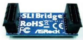
One ASRock SLI Bridge
One ASRock SLI/XFire Switch Card
One 80-conductor Ultra ATA 66/100/133 IDE Ribbon Cable
One Ribbon Cable for a 3.5-in Floppy Drive
Four Serial ATA (SATA) Data Cables (Optional)
One Serial ATA (SATA) HDD Power Cable (Optional)
One HDMI_SPDIF Cable (Optional)
One "ASRock WiFi_SPDIF I/O" I/O Panel Shield
1.2 Specifications
| Platform | - ATX Form Factor: 12.0-in x 8.8-in, 30.5 cm x 22.4 cm - All Solid Capacitor design |
| CPU | - Support for Socket AM2+/ AM2 processors: AMD Phenom™ FX / Phenom / Athlon 64 FX / Athlon 64 X2 Dual-Core / Athlon X2 Dual-Core / Athlon 64 / Sempron processor - AMD LIVE!™ Ready - Supports AMD's Cool 'n' Quiet™ Technology - FSB 2600 MHz (5.2 GT/s) (see CAUTION 1) - Supports Untied Overclocking Technology (see CAUTION 2) - Supports Hyper-Transport Technology |
| Chipset | -NVIDIA® nForce 750a SLI |
| Memory | -Dual Channel DDR2 Memory Technology (see CAUTION 3) - 4 x DDR2 DIMM slots -SupportDDR2 1066/800/667/533 non-ECC, un-buffered memory (see CAUTION 4) - Max. capacity of system memory: 8GB (see CAUTION 5) |
| Expansion Slot | - 2 x PCI Express 2.0 x16 slots (green @ x16 mode, blue @ x8 mode) - 1 x PCI Express x1 slot - 3 x PCI slots - Supports NVIDIA® SLITM (see CAUTION 6) - Supports NVIDIA® Hybrid SLITM (see CAUTION 7) |
| Audio | - 7.1 CH Windows® Vista™ Premium Level HD Audio with Content Protection -DAC with 110dB dynamic range (ALC890 Audio Codec) |
| LAN | -Gigabit LAN 10/100/1000 Mb/s -Giga PHY Realtek RTL8211B -Supports Wake-On-LAN |
| Rear Panel I/O | ASRock WiFi_SPDIF I/O - 1 x PS/2 Mouse Port - 1 x PS/2 Keyboard Port - 1 x Coaxial SPDIF Out Port - 1 x Optical SPDIF Out Port - 6 x Ready-to-Use USB 2.0 Ports - 1 x eSATAII Port - 1 x RJ-45 LAN Port with LED (ACT/LINK LED and SPEED LED) - 1 x IEEE 1394 Port -HD Audio Jack: Side Speaker/Rear Speaker/Central/Bass/Line in/Font Speaker/Microphone (see CAUTION 8) |
| Connector | -6 x SATAll 3.0Gb/s connectors, support RAID (RAID 0, RAID 1, RAID 0+1, JBOD and RAID 5), NCQ, AHCI and "Hot Plug" functions (see CAUTION 9) -1 x eSATAll 3.0Gb/s connector (shared with 1 SATAll connector) (see CAUTION 10) -1 x ATA133 IDE connector (supports 2 x IDE devices) -1 x Floppy connector -1 x DeskExpress Hot Plug Detection header -1 x COM port header -1 x HDMI_SPDIF header -1 x IEEE 1394 header -CPU/Chassis FAN connector -24 pin ATX power connector -8 pin 12V power connector -SLI/XFIRE power connector -CD in header -Front panel audio connector -2 x USB 2.0 headers (support 4 USB 2.0 ports) (see CAUTION 11) -1 x WiFi/E header (see CAUTION 12) |
| BIOS Feature | -8Mb AMI BIOS -AMI Legal BIOS -Supports "Plug and Play" -ACPI 1.1 Compliance Wake Up Events -Supports jumperfree -AMBIOS 2.3.1 Support -CPU, DRAM, NB, SB, VTT Voltage Multi-adjustment |
| Support CD | -Drivers, Utilities, AntiVirus Software (Trial Version) |
| Unique Feature | -ASRock OC Tuner (see CAUTION 13) -Intelligent Energy Saver (see CAUTION 14) -Hybrid Booster: -CPU Frequency Stepless Control (see CAUTION 15) -ASRock U-COP (see CAUTION 16) -Boot Failure Guard (B.F.G.) -ASRock AM2 Boost: ASRock Patented Technology to boost memory performance up to 12.5% (see CAUTION 17) |
| Hardware Monitor | - CPU Temperature Sensing -Chassis Temperature Sensing -CPU Fan Tachometer -Chassis Fan Tachometer |
| - CPU Quiet Fan - Voltage Monitoring: +12V, +5V, +3.3V, CPU Vcore | |
| OS | - Microsoft®Windows®XP / XP Media Center / XP 64-bit / Vista™ / Vista™ 64-bit compliant |
| Certifications | - FCC, CE, WHQL |
- For detailed product information, please visit our website: http://www.asrock.com
WARNING
Please realize that there is a certain risk involved with overclocking, including adjusting the setting in the BIOS, applying Untied Overclocking Technology, or using the third-party overclocking tools. Overclocking may affect your system stability, or even cause damage to the components and devices of your system. It should be done at your own risk and expense. We are not responsible for possible damage caused by overclocking.
CAUTION!
- If you install AM2 CPU on this motherboard, the system bus speed will be HT1.0 (2000 MT/s). If you install AM2+ CPU on this motherboard, the system bus speed will be HT3.0 (up to 5200 MT/s), and the HT Link frequency depends on the ability of the AM2+ CPU you adopt. Please refer to the CPU support list on our website for more information. ASRock website http://www.asrock.com
- This motherboard supports Untied Overclocking Technology. Please read "Untied Overclocking Technology" on page 45 for details.
- This motherboard supports Dual Channel Memory Technology. Before you implement Dual Channel Memory Technology, make sure to read the installation guide of memory modules on page 16 for proper installation.
- Whether 1066MHz memory speed is supported depends on the AM2+ CPU you adopt. If you want to adopt DDR2 1066 memory module on this motherboard, please refer to the memory support list on our website for the compatible memory modules. ASRock website http://www.asrock.com
- Due to the operating system limitation, the actual memory size may be less than 4GB for the reservation for system usage under Windows® XP and Windows® Vista™. For Windows® XP 64-bit and Windows® Vista™ 64-bit with 64-bit CPU, there is no such limitation.
-
This motherboard supports NVIDIA® SLITM technology. If you want to use SLITM function, please follow the instructions on page 20 to reverse the direction of ASRock SLI/XFire Switch Card. For the information of the compatible SLITM Mode PCI Express VGA cards, please refer to the "Supported PCI Express VGA Card List for SLITM Mode" on page 11. For the proper installation of PCI Express VGA card, please refer to the installation guide on page 18.
-
Hybrid SLI^TM feature should depend on the driver from NVIDIA. Currently, Hybrid SLI^TM driver is not ready yet. As long as NVIDIA releases Hybrid SLI^TM driver, we will update it to our website. Please visit our website for Hybrid SLI^TM driver and its operation guide in the future. ASRock website: http://www.asrock.com
- For microphone input, this motherboard supports both stereo and mono modes. For audio output, this motherboard supports 2-channel, 4-channel, 6-channel, and 8-channel modes. Please check the table on page 13 for proper connection.
- Before installing SATAll hard disk to SATAll connector, please read the "SATAll Hard Disk Setup Guide" on page 36 to adjust your SATAll hard disk drive to SATAll mode. You can also connect SATA hard disk to SATAll connector directly.
- This motherboard supports eSATAIl interface, the external SATAll specification. Please read "eSATAI l Interface Introduction" on page 33 for details about eSATAI and eSATAI installation procedures.
- Power Management for USB 2.0 works fine under Microsoft® Windows® Vista™ 64-bit / Vista™ / XP 64-bit / XP SP1 or SP2.
- WiFi/E header supports WiFi+AP function with ASRock WiFi-802.11g or WiFi-802.11n module, an easy-to-use wireless local area network (WLAN) adapter. It allows you to create a wireless environment and enjoy the convenience of wireless network connectivity. Please visit our website for the availability of ASRock WiFi-802.11g or WiFi-802.11n module. ASRock website http://www.asrock.com
- It is a user-friendly ASRock overclocking tool which allows you to surveil your system by hardware monitor function and overclock your hardware devices to get the best system performance under Windows® environment. Please visit our website for the operation procedures of ASRock OC Tuner. ASRock website: http://www.asrock.com
- Featuring an advanced proprietary hardware and software design, Intelligent Energy Saver is one of the options in ASRock OC Tuner. The voltage regulator can reduce the number of output phases to improve efficiency when the CPU cores are idle. In other words, it is able to provide exceptional power saving and improve power efficiency without sacrificing computing performance. To use Intelligent Energy Saver function, please enable Cool 'n' Quiet option in the BIOS setup in advance. Please visit our website for the operation procedures of Intelligent Energy Saver. ASRock website: http://www.asrock.com
- Although this motherboard offers stepless control, it is not recommended to perform over-clocking. Frequencies other than the recommended CPU bus frequencies may cause the instability of the system or damage the CPU.
-
While CPU overheat is detected, the system will automatically shutdown. Before you resume the system, please check if the CPU fan on the motherboard functions properly and unplug the power cord, then plug it back again. To improve heat dissipation, remember to spray thermal grease between the CPU and the heatsink when you install the PC system.
-
This motherboard supports ASRock AM2 Boost overclocking technology for AM2 CPU. If you enable this function in the BIOS setup, the memory performance will improve up to 12.5% , but the effect still depends on the AM2 CPU you adopt. Enabling this function will overclock the chipset/CPU reference clock. However, we can not guarantee the system stability for all CPU/DRAM configurations. If your system is unstable after AM2 Boost function is enabled, it may not be applicative to your system. You may choose to disable this function for keeping the stability of your system.
1.3 Minimum Hardware Requirement Table for Windows Vista™ Premium 2008 and Basic Logo
For system integrators and users who purchase this motherboard and plan to submit Windows® Vista™ Premium 2008 and Basic logo, please follow below table for minimum hardware requirement.
| CPU | Sempron 2800+ |
| Memory | 1GB system memory (Premium) |
| 512MB system memory (Basic) | |
| VGA | DX10 with WDDM Driver |
| with 128bit VGA memory (Premium) | |
| with 64bit VGA memory (Basic) |
- After June 1, 2008, all Windows® Vista™ systems are required to meet above minimum hardware requirements in order to qualify for Windows® Vista™ Premium 2008 logo.
1.4 Supported PCI Express VGA Card List for SLI^TM Mode
(for Windows XP / XP 64-bit / Vista™ / Vista™ 64-bit only)
| Graphics Chip Vendor | Model Name | Chipset Name |
| NVIDIA | ASUS EN8800GTX | GeForce 8800GTX |
| ASUS EN8600GT/2DHT | GeForce 8600GT | |
| ASUS EN7950GX2 * | GeForce 7950GX2 | |
| ASUS EN7900GT TOP | GeForce 7900GT | |
| ASUS EN7800GT | GeForce 7800GT | |
| ASUS EN7600GSSILENT | GeForce 7600GT | |
| ASUS EN7600GT/2DHT | GeForce 7600GS | |
| ASUS EN6800LE | GeForce 6800LE | |
| ASUS Extreme N6800/TD | GeForce 6800 | |
| ALBATRON PC6600GT | GeForce 6600GT | |
| GIGABYTE GV-NX66256DP2 | GeForce 6600 | |
| LEADTEK PX7900GS TDH | GeForce 7900GS | |
| LEADTEK PX7300GS TDH * | GeForce 7300GS | |
| MSI 7300GT-TD256EH | GeForce 7300GT |
- These two cards can only work under Windows® XP / XP 64-bit OS.
For the latest updates of the supported PCI Express VGA card list for SLI^TM Mode, please visit our website for details.
ASRock website: http://www.asrock.com/support/index.htm
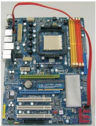
1.5 Motherboard Layout
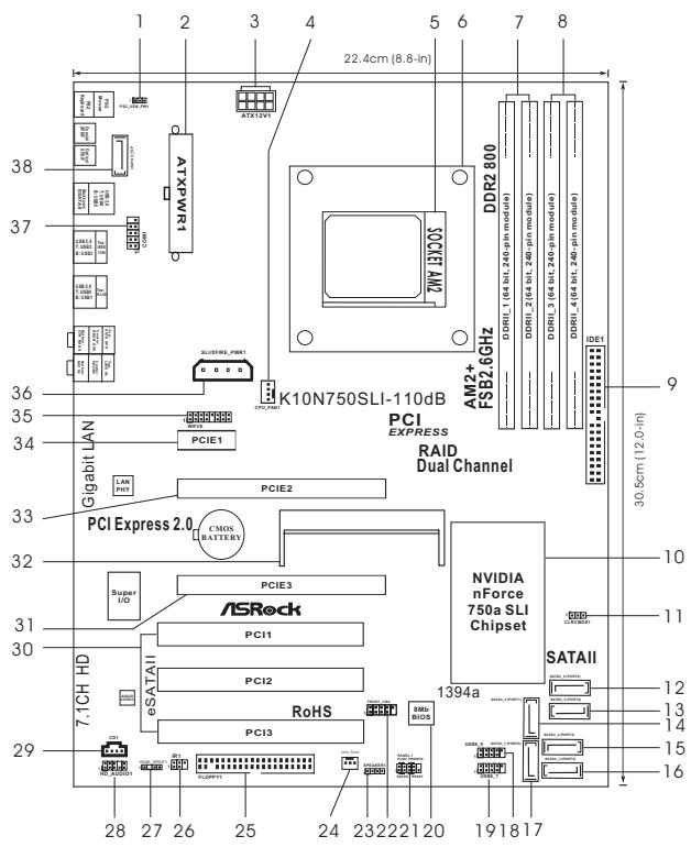
1 PS2_USB_PWM1 Jumper
2 ATX Power Connector (ATXPWR1)
3 ATX 12V Power Connector (ATX12V1)
4 CPU Fan Connector (CPU_FAN1)
5 AM2 940-Pin CPU Socket
6 CPU Heatsink Retention Module
7 2x240-pin DDR2 DIMM Slots
(Dual Channel A: DDRII_1, DDRII_2; Yellow)
8 2x240-pin DDR2 DIMM Slots
Dual Channel B: DDRII_3, DDRII_4; Orange)
9 Primary IDE Connector (IDE1, Blue)
10 NVIDIA nForce 750a SLI Chipset
11 Clear CMOS Jumper (CLRCMOS1)
12 SATAll Connector (SATAll_6 (PORT5))
13 SATAll Connector (SATAI5 (PORT4))
14 SATAll Connector (SATAI_2 (PORT1))
15 SATAll Connector (SATAll_4(PORT3))
16 SATAll Connector (SATAI3 (PORT2))
17 SATAll Connector (SATAI_1 (PORT0))
18 USB 2.0 Header (USB8_9, Blue)
19 USB 2.0 Header (USB6_7, Blue)
20 SPI BIOS Chip
21 System Panel Header (PANEL1)
22 Front Panel IEEE 1394 Header
(FRONT_1394)
23 Chassis Speaker Header (SPEAKER 1)
24 Chassis Fan Connector (CHA_FAN1)
25 Floppy Connector (FLOPPY1)
26 DeskExpress Hot Plug Detection Header (IR1)
27 HDMI_SPDIF Header (HDMI_SPDIF1)
28 Front Panel Audio Header (HD AUDIO01)
29 Internal Audio Connector: CD1 (Black)
30 PCI Slots (PCI1- 3)
31 PCI Express x16 Slot (PCIE3, Blue)
32 SLI/XFire Switch Card Retention Slot
33 PCI Express x16 Slot (PCIE2, Green)
34 PCI Express x1 Slot (PCIE1, White)
35 WiFi/E Header (WIFI/E)
36 SLI/XFIRE Power Connector
37 COM Port Header (COM1)
38 eSATAI Connector (eSATAI_TOP)
1.6 ASRock WIFI_SPDIF I/O
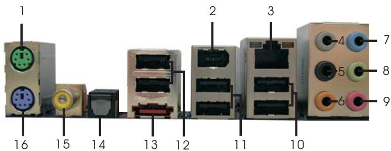
1 PS/2 Mouse Port (Green)
9 Microphone (Pink)
2 IEEE 1394 Port
10 USB 2.0 Ports (USB01)
3 LAN RJ-45 Port
11 USB 2.0 Ports (USB23)
4 Side Speaker (Gray)
12 USB 2.0 Ports (USB45)
5 Rear Speaker (Black)
13 eSATAI Port
6 Central/Bass (Orange)
14 Optical SPDIF Out Port
7 Line In (Light Blue)
15 Coaxial SPDIF Out Port
*8 Front Speaker (Lime)
16 PS/2 Keyboard Port (Purple)
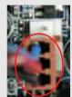
- There are two LED next to the LAN port. Please refer to the table below for the LAN port LED indications.
LAN Port LED Indications
SPEEDLED
| Status | Description |
| Off | 10Mbps connection |
| Orange | 100Mbps connection |
| Green | 1Gbps connection |
Activity/Link LED
| Status | Description |
| Off | No link |
| Orange | Linked |
| Blinking | Data Activity |
SPEED ACT/LINK
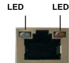
LAN Port
** If you use 2-channel speaker, please connect the speaker's plug into "Front Speaker Jack". See the table below for connection details in accordance with the type of speaker you use.
TABLE for Audio Output Connection
| Audio Output Channels | Front Speaker (No. 8) | Rear Speaker (No. 5) | Central / Bass (No. 6) | Side Speaker (No. 4) |
| 2 | V | -- | -- | -- |
| 4 | V | V | -- | -- |
| 6 | V | V | V | -- |
| 8 | V | V | V | V |
To enable Multi-Streaming function, you need to connect a front panel audio cable to the front panel audio header. After restarting your computer, you will find "Mixer" tool on your system. Please select "Mixer ToolBox", click "Enable playback multi-streaming", and click
"ok". Choose "2CH", "4CH", "6CH", or "8CH" and then you are allowed to select "Realtek HDA Primary output" to use Rear Speaker, Central/Bass, and Front Speaker, or select "Realtek HDA Audio 2nd output" to use front panel audio.
2. Installation
This is an ATX form factor (12.0-in x 8.8-in, 30.5cm× 22.4cm ) motherboard.
Before you install the motherboard, study the configuration of your chassis to ensure that the motherboard fits into it.
Pre-installation Precautions
Take note of the following precautions before you install motherboard components or change any motherboard settings.

Before you install or remove any component, ensure that the power is switched off or the power cord is detached from the power supply. Failure to do so may cause severe damage to the motherboard, peripherals, and/or components.
- Unplug the power cord from the wall socket before touching any component.
- To avoid damaging the motherboard components due to static electricity, NEVER place your motherboard directly on the carpet or the like. Also remember to use a grounded wrist strap or touch a safety grounded object before you handle components.
- Hold components by the edges and do not touch the ICs.
- Whenever you uninstall any component, place it on a grounded anti-static pad or in the bag that comes with the component.
- When placing screws into the screw holes to secure the motherboard to the chassis, please do not over-tighten the screws! Doing so may damage the motherboard.
2.1 CPU Installation
Step 1. Unlock the socket by lifting the lever up to a 90^ angle.
Step 2. Position the CPU directly above the socket such that the CPU corner with the golden triangle matches the socket corner with a small triangle.
Step 3. Carefully insert the CPU into the socket until it fits in place.

The CPU fits only in one correct orientation. DO NOT force the CPU into the socket to avoid bending of the pins.
Step 4. When the CPU is in place, press it firmly on the socket while you push down the socket lever to secure the CPU. The lever clicks on the side tab to indicate that it is locked.
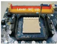
STEP1:
Lift Up The Socket Lever
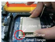
STEP 2/STEP3:
Match The CPU Golden Triangle To The Socket Corner Small Triangle
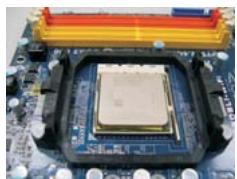
STEP4:
Push Down And Lock The Socket Lever
2.2 Installation of CPU Fan and Heatsink
After you install the CPU into this motherboard, it is necessary to install a larger heatsink and cooling fan to dissipate heat. You also need to spray thermal grease between the CPU and the heatsink to improve heat dissipation. Make sure that the CPU and the heatsink are securely fastened and in good contact with each other. Then connect the CPU fan to the CPU FAN connector (CPU_FAN1, see Page 12, No. 4). For proper installation, please kindly refer to the instruction manuals of the CPU fan and the heatsink.
2.3 Installation of Memory Modules (DIMM)
This motherboard provides four 240-pin DDR2 (Double Data Rate 2) DIMM slots, and supports Dual Channel Memory Technology. For dual channel configuration, you always need to install identical (the same brand, speed, size and chip-type) DDR2 DIMM pair in the slots of the same color. In other words, you have to install identical DDR2 DIMM pair in Dual Channel A (DDRII_1 and DDRII_2; Yellow slots; see p.12 No.7) or identical DDR2 DIMM pair in Dual Channel B (DDRII_3 and DDRII_4; Orange slots; see p.12 No.8), so that Dual Channel Memory Technology can be activated. This motherboard also allows you to install four DDR2 DIMMs for dual channel configuration, and please install identical DDR2 DIMMs in all four slots. You may refer to the Dual Channel Memory Configuration Table below.
Dual Channel Memory Configurations
| DDRII_1 (Yellow Slot) | DDRII_2 (Yellow Slot) | DDRII_3 (Orange Slot) | DDRII_4 (Orange Slot) | |
| (1) | Populated | Populated | - | - |
| (2) | - | - | Populated | Populated |
| (3)* | Populated | Populated | Populated | Populated |
- For the configuration (3), please install identical DDR2 DIMMs in all four slots.

- If you want to install two memory modules, for optimal compatibility and reliability, it is recommended to install them in the slots of the same color. In other words, install them either in the set of yellow slots (DDRII_1 and DDRII_2), or in the set of orange slots (DDRII_3 and DDRII_4).
- If only one memory module or three memory modules are installed in the DDR2 DIMM slots on this motherboard, it is unable to activate the Dual Channel Memory Technology.
- If a pair of memory modules is NOT installed in the same Dual Channel, for example, installing a pair of memory modules in DDR1_1 and DDR1_3, it is unable to activate the Dual Channel Memory Technology.
- It is not allowed to install a DDR memory module into DDR2 slot; otherwise, this motherboard and DIMM may be damaged.
Installing a DIMM

Please make sure to disconnect power supply before adding or removing DIMMs or the system components.
Step 1. Unlock a DIMM slot by pressing the retaining clips outward.
Step 2. Align a DIMM on the slot such that the notch on the DIMM matches the break on the slot.

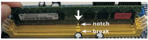

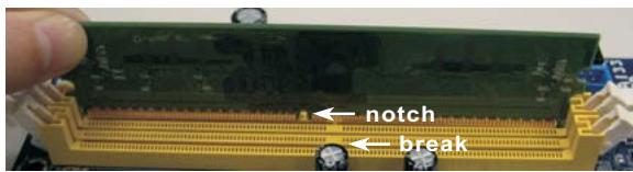

The DIMM only fits in one correct orientation. It will cause permanent damage to the motherboard and the DIMM if you force the DIMM into the slot at incorrect orientation.
Step 3. Firmly insert the DIMM into the slot until the retaining clips at both ends fully snap back in place and the DIMM is properly seated.
2.4 Expansion Slots (PCI and PCI Express Slots)
There are 3 PCI slots and 3 PCI Express slots on this motherboard.
PCI Slots: PCI slots are used to install expansion cards that have the 32-bit PCI interface.
PCIE Slots: PCIE1 (PCIE x1 slot; White) is used for PCI Express cards with x1 lane width cards, such as Gigabit LAN card, SATA2 card and ASRock PCIE_DE card.
PCIE2 (PCIE x16 slot; Green) is used for PCI Express x16 lane width graphics cards, or used to install PCI Express graphics cards to support SLITM function.
PCIE3 (PCIE x16 slot; Blue) is used for PCI Express x1 lane width cards, such as Gigabit LAN card, SATA2 card, etc., or used to install PCI Express graphics cards to support SLI^TM function.
PCIE2 / PCIE3 / SLI/XFire Switch Card Retention Slot
Configurations
| PCIE2 Slot (Green) | PCIE3 Slot (Blue) | SLI/XFire Switch Card Retention Slot | |
| Single Graphics Card | PCIE x16 | PCIE x1 | |
| Dual Graphics Cards in SLITM Mode | PCIE x8 | PCIE x8 |

- If you plan to install only one PCI Express VGA card on this motherboard, please install it on PCIe2 slot (Green). In this mode, you do not need to adjust the default setting of ASRock SLI/XFire Switch Card, and please do not remove or lose ASRock SLI/XFire Switch Card when it is still in working condition.
- For the information of the compatible SLI^TM Mode PCI Express VGA cards and SLI^TM setup procedures, please refer to the "Supported PCI Express VGA Card List for SLI^TM Mode" on page 11 and "SLI™ Operation Guide" on page 20.
- If you want to use ASRock DeskExpress function on this motherboard, please install ASRock PCIE_DE card on PCIE1 slot.
Installing an expansion card
Step 1. Before installing the expansion card, please make sure that the power supply is switched off or the power cord is unplugged. Please read the documentation of the expansion card and make necessary hardware settings for the card before you start the installation.
Step 2. Remove the system unit cover (if your motherboard is already installed in a chassis).
Step 3. Remove the bracket facing the slot that you intend to use. Keep the screws for later use.
Step 4. Align the card connector with the slot and press firmly until the card is completely seated on the slot.
Step 5. Fasten the card to the chassis with screws.
Step 6. Replace the system cover.
2.5 SLITM Operation Guide
This motherboard supports NVIDIA® SLITM (Scalable Link Interface) technology that allows you to install two identical NVIDIA® SLITM enabled PCI Express x16 graphics cards. Currently, NVIDIA® SLITM technology supports Windows® XP, XP 64-bit, Vista™ and Vista™ 64-bit OS. Please follow the installation procedures in this section.

SLITM Technology Requirements
- You should have two identical SLIT™-ready graphics cards that are NVIDIA® certified.
- Make sure that your graphics card driver supports the NVIDIA® SLI™ technology. Download the latest driver from the NVIDIA® website (www.nvidia.com).
- Make sure that your power supply unit (PSU) can provide at least the minimum power required by your system.
Enjoy the benefit of SLI^TM
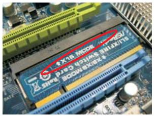
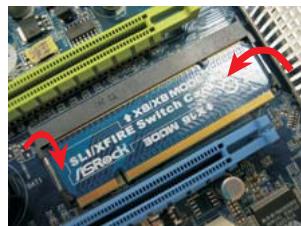
Step 1. There is one ASRock SLI/XFire Switch Card factory-mounted on this motherboard. This card served as a switch between the default mode (x16) and SLI mode (x8 / x8). ASRock SLI/XFire Switch Card is factory-mounted with its default mode (x16) side toward the retention slot base.
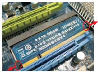
Step 2. To change it to SLI Mode, you need to reverse the direction of ASRock SLI/ XFire Switch Card. Please simultaneously pull open both the retention arms that hold the card in position. The card itself will spring away from the retention slot. Take it out gently by holding its edges, and keep away from touching the connectors (Golden Fingers).
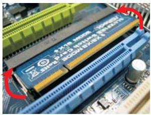
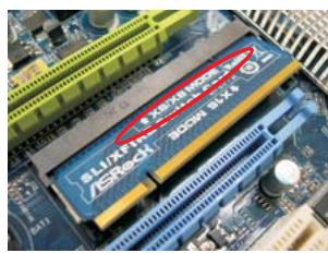
Step 3. Reverse the card direction so as to have the "X8 / X8 MODE" wording side toward the retention slot base. Insert the card into the bottom of the base.
Step 4. Push the card down into the retention slot till both the retention arms firmly hold the card into position. Also, keep away from touching the connectors (Golden Fingers).
Step 5. Install the identical SLITM-ready graphics cards that are NVIDIA® certified because different types of graphics cards will not work together properly. (Even the GPU chips version shall be the same.) Insert one graphics card into PCIE2 slot and another graphics card to PCIE3 slot. Make sure that the cards are properly seated on the slots.
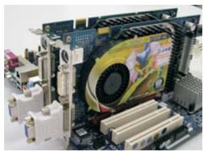
Step 6. If required, connect an auxiliary power source to the PCI Express graphics cards.
Step 7. Align and insert the SLI Bridge to the goldfingers on each graphics card. Make sure that the SLI Bridge is firmly in place.
Step 8. Connect a VGA cable or a DVI-I cable to the monitor connector and the DVI connector of the graphics card that is inserted to PCIE2 slot.
Step 9. Connect a 4-pin ATX power cable to SLI/XFIRE power connector.
Step 10. Install the graphics card drivers to your system. After that, you can enable the Multi-Graphics Processing Unit (GPU) feature in the NVIDIA® nView system tray utility. Please follow the below procedures to enable the multi-GPU feature.
For Windows XP / XP 64-bit OS:
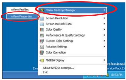
A. Click the NVIDIA Settings icon on your Windows® taskbar.

B. From the pop-up menu, select nView Desktop Manager, and then click nView Properties.
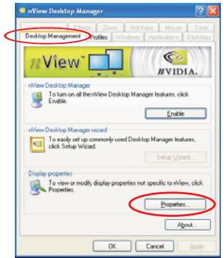
C. From the nView Desktop Manager window, select the Desktop Management tab.
D. Click Properties to display the Display Properties dialog box.
E. From the Display Properties dialog box, select the Settings tab then click Advanced.
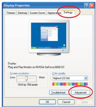
F. Select the NVIDIA GeForce tab.
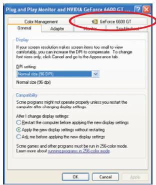
G. Click the slider to display the following screen, then select the SLI
multi-GPU item.
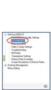
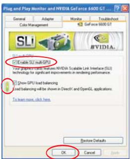
H. Click the Enable SLI multi-GPU check box.
- Click OK when done.
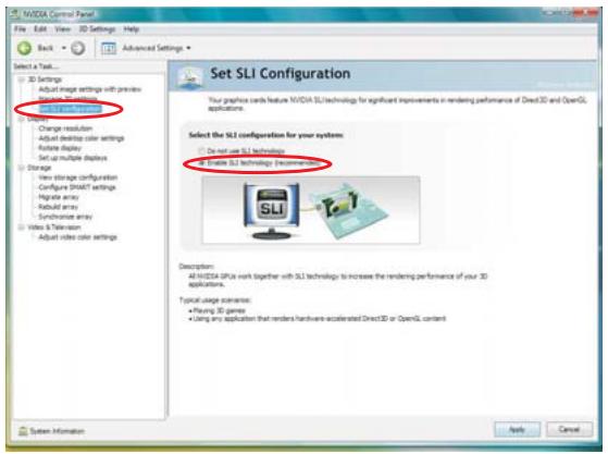
For Windows® Vista™ / Vista™ 64-bit OS:
A. Click the Start icon on your Windows taskbar.
B. From the pop-up menu, select All Programs, and then click NVIDIA Corporation.
C. Select NVIDIA Control Panel tab.
D. Select Control Panel tab.
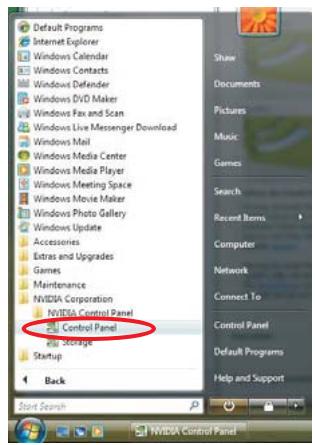
E. From the pop-up menu, select Set SLI configuration, and then click Apply.
- SLITM appearing here is a registered trademark of NVIDIA® Technologies Inc., and is used only for identification or explanation and to the owners' benefit, without intent to infringe.
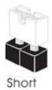
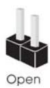
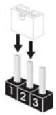
2.6 Jumpers Setup
The illustration shows how jumpers are setup. When the jumper cap is placed on pins, the jumper is "Short". If no jumper cap is placed on pins, the jumper is "Open". The illustration shows a 3-pin jumper whose pin1 and pin2 are "Short" when jumper cap is placed on these 2 pins.
Jumper
Setting
PS2_USB_PWM1
(see p.12, No. 1)


Short pin2, pin3 to enable
+5VSB (standby) for PS/2 or
USB wake up events.
Note: To select +5VSB, it requires 2 Amp and higher standby current provided by power supply.
Clear CMOS Jumper
(CLRCMOS1)
(see p.12, No. 11)

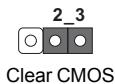
Note: CLRCMOS1 allows you to clear the data in CMOS. The data in CMOS includes system setup information such as system password, date, time, and system setup parameters. To clear and reset the system parameters to default setup, please turn off the computer and unplug the power cord from the power supply. After waiting for 15 seconds, use a jumper cap to short pin2 and pin3 on CLRCMOS1 for 5 seconds. However, please do not clear the CMOS right after you update the BIOS. If you need to clear the CMOS when you just finish updating the BIOS, you must boot up the system first, and then shut it down before you do the clear-CMOS action.
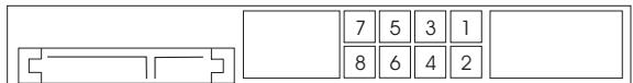
2.7 Onboard Headers and Connectors

Onboard headers and connectors are NOT jumpers. Do NOT place jumper caps over these headers and connectors. Placing jumper caps over the headers and connectors will cause permanent damage of the motherboard!
Floppy Connector
(33-pinFLOPPY1)
(see p.12, No. 25)
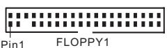
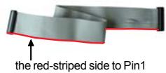
Note: Make sure the red-striped side of the cable is plugged into Pin1 side of the connector.
Primary IDE connector (Blue)
(39-pin IDE1, see p.12, No. 9)
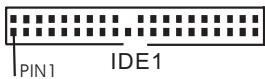
connect the blue end to the motherboard

80-conductor ATA 66/100/133 cable
Note: Please refer to the instruction of your IDE device vendor for the details.
Serial ATA II Connectors
(SATAI_1 (PORT0):
see p.12, No. 17)
(SATAI_2 (PORT1):
see p.12, No. 14)
(SATAI_3 (PORT2):
see p.12, No. 16)
(SATAI_4 (PORT3):
see p.12, No. 15)
(SATAI_5 (PORT4):
see p.12, No. 13)
(SATAI_6 (PORT5):
see p.12, No. 12)
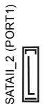
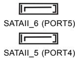

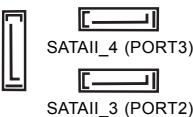
These six Serial ATA11
(SATAII) connectors support
SATA data cables for internal
storage devices. The current
SATAI interface allows up to
3.0 Gb/s data transfer rate.

SATAI1_6 (PORT5) connector can be used for internal storage device or be connected to eSATAI1 connector to support eSATAI1 device. Please read "eSATAI1 Interface Introduction" on page 33 for details about eSATAI1 and eSATAI1 installation procedures.
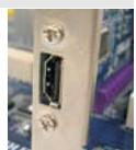
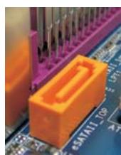
eSATAI Connector
(eSATAI_TOP: see p.12, No. 38)

This eSATAI connector supports SATA data cable for external SATAI function. The current eSATAI interface allows up to 3.0 Gb/s data transfer rate.
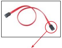
Serial ATA (SATA)
Data Cable
(Optional)
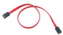
Either end of the SATA data cable can be connected to the SATA / SATAII hard disk or the SATAII connector on this motherboard. You can also use the SATA data cable to connect SATAII_6 (PORT5) connector and eSATAII connector.
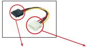
Serial ATA (SATA)
Power Cable
(Optional)
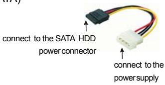
Please connect the black end of SATA power cable to the power connector on each drive. Then connect the white end of SATA power cable to the power connector of the power supply.
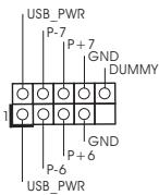
USB 2.0 Headers
(9-pin USB8_9)
(see p.12 No. 18)
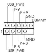
Besides six default USB 2.0 ports on the I/O panel, there are two USB 2.0 headers on this motherboard. Each USB 2.0 header can support two USB 2.0 ports.
(9-pin USB6_7)
(see p.12 No. 19)
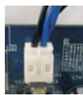
WiFi/E Header
(15-pin WIFI/E)
(see p.12 No. 35)
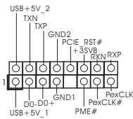
This header supports WiFi+AP function with ASRock WiFi-802.11g or WiFi-802.11n module, an easy-to-use wireless local area network (WLAN) adapter. It allows you to create a wireless environment and enjoy the convenience of wireless network connectivity.

If you don't plan to use WiFi+AP functin on this motherboard, this header can be used as a 4-Pin USB 2.0 header to support one USB 2.0 port. To connect the
4-Pin USB device cable to this header, please refer to this picture for proper installation.
DeskExpress Hot Plug Detection
Header
(5-pin IR1)
(see p.12 No. 26)
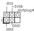
This header supports the Hot Plug detection function for ASRock DeskExpress.
Internal Audio Connectors
(4-pin CD1)
(CD1: see p.12, No. 29)

CD1
This connector allows you to receive stereo audio input from sound sources such as a CD-ROM, DVD-ROM, TV tuner card, or MPEG card.
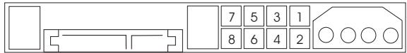
Front Panel Audio Header
(9-pin HD=AUDIO1)
(see p.12, No. 28)
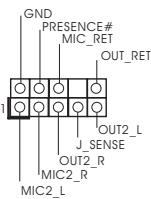
This is an interface for the front panel audio cable that allows convenient connection and control of audio devices.

- High Definition Audio supports Jack Sensing, but the panel wire on the chassis must support HDA to function correctly. Please follow the instruction in our manual and chassis manual to install your system.
- If you use AC'97 audio panel, please install it to the front panel audio header as below:
A. Connect Mic_IN (MIC) to MIC2_L.
B. Connect Audio_R (RIN) to OUT2_R and Audio_L (LIN) to OUT2_L.
C. Connect Ground (GND) to Ground (GND).
D. MIC_RET and OUT_RET are for HD audio panel only. You don't need to connect them for AC'97 audio panel.
E. Enter BIOS Setup Utility. Enter Advanced Settings, and then select Chipset Configuration. Set the Front Panel Control option from [Auto] to [Enabled].
F. Enter Windows system. Click the icon on the lower right hand taskbar to enter Realtek HD Audio Manager.
For Windows XP / XP 64-bit OS:
Click "Audio I/O", select "Connector Settings", choose
"Disable front panel jack detection", and save the change by clicking "OK".
For Windows® Vista™ / Vista™ 64-bit OS:
Click the right-top "Folder" icon , choose "Disable front
panel jack detection", and save the change by clicking "OK".
System Panel Header
(9-pin PANEL1)
(see p.12, No. 21)

This header accommodates several system front panel functions.
Chassis Speaker Header
(4-pin SPEAKER 1)
(see p.12, No. 23)
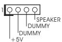
Please connect the chassis speaker to this header.
Chassis Fan Connector
(3-pin CHA_FAN1)
(see p.12, No. 24)
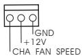
Please connect a chassis fan cable to this connector and match the black wire to the ground pin.
CPU Fan Connector
(4-pinCPU_FAN1)
(see p.12, No. 4)
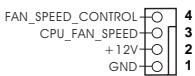
Please connect the CPU fan cable to this connector and match the black wire to the ground pin.

Though this motherboard provides 4-Pin CPU fan (Quiet Fan) support, the 3-Pin CPU fan still can work successfully even without the fan speed control function. If you plan to connect the 3-Pin CPU fan to the CPU fan connector on this
motherboard, please connect it to Pin 1-3.
Pin 1-3 Connected
3-Pin Fan Installation
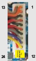
ATX Power Connector
(24-pinATXPWR1)
(see p.12, No. 2)
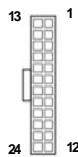
Please connect an ATX power supply to this connector.

Though this motherboard provides 24-pin ATX power connector, it can still work if you adopt a traditional 20-pin ATX power supply. To use the 20-pin ATX power supply, please plug your power supply along with Pin 1 and Pin 13.
20-Pin ATX Power Supply Installation
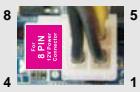
ATX 12V Power Connector
(8-pin ATX12V1)
(see p.12, No. 3)

Please note that it is necessary to connect a power supply with ATX 12V plug to this connector. Failing to do so will cause power up failure.

Though this motherboard provides 8-pin ATX 12V power connector, it can still work if you adopt a traditional 4-pin ATX 12V power supply. To use the 4-pin ATX power supply, please plug your power supply along with Pin 1 and Pin 5.
4-Pin ATX 12V Power Supply Installation
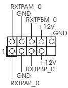
SLI/XFIRE Power Connector
(4-pin SLI/XFIRE_PWR1)
(see p.12 No. 36)

SLI/XFIRE_POWER1
It is not necessary to use this connector, but please connect it with a hard disk power connecr when two graphics cards are plugged to this motherboard at the same time.
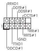
IEEE 1394 Header
(9-pin FRONT_1394)
(see p.12 No. 22)
Besides one default IEEE 1394 port on the I/O panel, there is one IEEE 1394 header (FRONT_1394) on this motherboard. This IEEE 1394 header can support one IEEE 1394 port.
Serial port Header
(9-pin COM1)
(see p.12 No.37)
This COM1 header supports a serial port module.
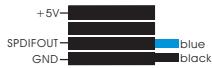
HDMI_SPDIF Header
(3-pin HDMI_SPDIF1)
(see p.12, No. 27)

HDMI_SPDIF header, providing SPDIF audio output to HDMI VGA card, allows the system to connect HDMI Digital TV/ projector/LCD devices. Please connect the HDMI_SPDIF connector of HDMI VGA card to this header.
HDMI_SPDIF Cable
(Optional)
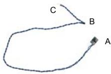
Please connect the black end (A) of HDMI_SPDIF cable to the HDMI_SPDIF header on the motherboard. Then connect the white end (B or C) of HDMI_SPDIF cable to the HDMI_SPDIF connector of HDMI VGA card.
A. black end
B. white end (2-pin)

C. white end (3-pin)
2.8 HDMI_SPDIF Header Connection Guide
HDMI (High-Definition Multi-media Interface) is an all-digital audio/video specification, which provides an interface between any compatible digital audio/video source, such as a set-top box, DVD player, A/V receiver and a compatible digital audio or video monitor, such as a digital television (DTV). A complete HDMI system requires a HDMI VGA card and a HDMI ready motherboard with a HDMI_SPDIF header. This motherboard is equipped with a HDMI_SPDIF header, which provides SPDIF audio output to HDMI VGA card, allows the system to connect HDMI Digital TV/projector/ LCD devices. To use HDMI function on this motherboard, please carefully follow the below steps.
Step 1. Install the HDMI VGA card to the PCI Express Graphics slot on this motherboard. For the proper installation of HDMI VGA card, please refer to the installation guide on page 18.
Step 2. Connect the black end (A) of HDMI_SPDIF cable to the HDMI_SPDIF header (HDMI_SPDIF1, yellow, see page 12, No. 27) on the motherboard.

Make sure to correctly connect the HDMI_SPDIF cable to the motherboard and the HDMI VGA card according to the same pin definition. For the pin definition of HDMI_SPDIF header and HDMI_SPDIF cable connectors, please refer to page 31. For the pin definition of HDMI_SPDIF connectors on HDMI VGA card, please refer to the user manual of HDMI VGA card vendor. Incorrect connection may cause permanent damage to this motherboard and the HDMI VGA card.
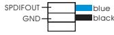
Step 3. Connect the white end (B or C) of HDMI_SPDIF cable to the HDMI_SPDIF connector of HDMI VGA card. (There are two white ends (2-pin and 3-pin) on HDMI_SPDIF cable. Please choose the appropriate white end according to the HDMI_SPDIF connector of the HDMI VGA card you install.
white end (2-pin) (B)

white end (3-pin) (C)

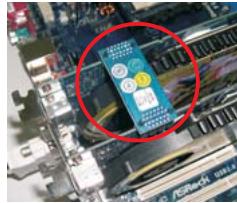
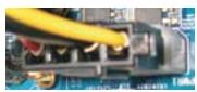
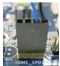
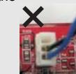
Please do not connect the white end of HDMI_SPDIF cable to the wrong connector of HDMI VGA card or other VGA card. Otherwise, the motherboard and the
VGA card may be damaged. For example, this picture shows the wrong example of connecting HDMI_SPDIF cable to the fan connector of PCI Express VGA card. Please refer to the VGA card user manual for connector usage in advance.
Step 4. Connect the HDMI output connector on HDMI VGA card to HDMI device, such as HDTV. Please refer to the user manual of HDTV and HDMI VGA card vendor for detailed connection procedures.
Step 5. Install HDMI VGA card driver to your system.
2.9 eSATAII Interface Introduction
What is eSATAI?
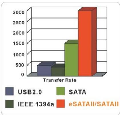
This motherboard supports eSATAIl interface, the external SATAll specification. eSATAll allows you to enjoy the SATAll function provided by the I/O of your computer, offering the high speed data transfer rate up to 3.0Gb/s, and the convenient mobility like USB. eSATAll is equipped with Hot Plug capability that enables you to exchange drives easily. For example, with eSATAll interface, you may simply plug your eSATAll hard disk to the eSATAll ports instead of opening your chassis to exchange your SATAll hard disk. Currently, on the market, the data transfer rate of USB 2.0 is up to 480Mb/s, and for IEEE 1394 is up to 400Mb/ s. However, eSATAll provides the data transfer rate up to 3000Mb/s, which is much higher than USB 2.0 and IEEE 1394, and still keeps the convenience of Hot Plug feature. Therefore, on the basis of the advantageous transfer speed and the facilitating mobile capability, in the near future, eSATAll will replace USB 2.0 and IEEE 1394 to be a trend for external interface.
NOTE:
- If you set "SATA Operation Mode" option in BIOS setup to AHCI or RAID mode, Hot Plug function is supported with eSATAI devices. Therefore, you can insert or remove your eSATAI devices to the eSATAI ports while the system is power-on and in working condition.
- If you set "SATA Operation Mode" option in BIOS setup to non-RAID mode, Hot Plug function is not supported with eSATAI1 devices. If you still want to use eSATAI1 function in non-RAID mode, please insert or remove your eSATAI1 devices to the eSATAI1 ports only when the system is power-off.
- If you want to use the eSATAI1 HDD as an OS disk, please set "SATA Operation Mode" option in BIOS setup to non-RAID mode. If you want to use the eSATAI1 HDD as a removable data disk, please set "SATA Operation Mode" option in BIOS setup to RAID mode. If you want to add the eSATAI1 HDD as a RAID disk, please set "SATA Operation Mode" option in BIOS setup to RAID mode.
- Please do not configure your eSATAI HDD as a RAID disk; otherwise, it may affect the Hot Plug function that eSATAI HDD should have.
- Please refer to page 41 to 44 for detailed information of RAID mode, non-RAID mode and AHCI mode.
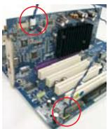
How to install eSATAI?
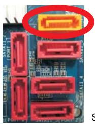
SATAI1_6(PORT5)
esATAI_TOP
- In order to enable the eSATAI port of the I/O shield, you need to connect the orange SATAI connector (SATAI_6 (PORT5); see p.12 No.12) and the eSATAI connector (eSATAI_TOP; see p.12 No.38) with a SATA data cable first.
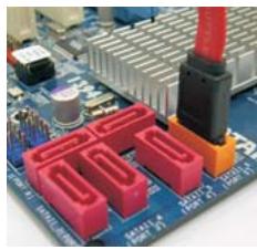
Connect the SATA data cable to the orange SATAll connector (SATAII_6 (PORT5))
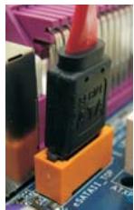
Connect the SATA data cable to the eSATAI connector (eSATAI_TOP)
- Use the eSATAI device cable to connect eSATAI device and the eSATAI port of the I/O shield according to the eSATAI connector that you connect the SATA data cable.
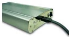
Connect one end of the eSATAI device cable to eSATAI device

Connect the other end of the eSATAI device cable to eSATAI port of the I/O shield
Comparison between eSATAI and other devices
| IEEE 1394 | 400Mb/s |
| USB 2.0 | 480Mb/s |
| SATA | 1.5Gb/s (1500Mb/s) |
| eSATAI/SATAII | 3.0Gb/s (3000Mb/s) |
2.10 SATAll Hard Disk Setup Guide
Before installing SATAll hard disk to your computer, please carefully read below SATAll hard disk setup guide. Some default setting of SATAll hard disks may not be at SATAll mode, which operate with the best performance. In order to enable SATAll function, please follow the below instruction with different vendors to correctly adjust your SATAll hard disk to SATAll mode in advance; otherwise, your SATAll hard disk may fail to run at SATAll mode.
Western Digital
If pin 5 and pin 6 are shorted, SATA 1.5Gb/s will be enabled.
On the other hand, if you want to enable SATAll 3.0Gb/s, please remove the jumpers from pin 5 and pin 6.
SAMSUNG
If pin 3 and pin 4 are shorted, SATA 1.5Gb/s will be enabled.
On the other hand, if you want to enable SATAII 3.0Gb/s, please remove the jumpers from pin 3 and pin 4.
HITACHI
Please use the Feature Tool, a DOS-bootable tool, for changing various ATA
features. Please visit HITACHI's website for details:
http://www.hitigist.com/hdd/support/download.htm

The above examples are just for your reference. For different SATAll hard disk products of different vendors, the jumper pin setting methods may not be the same. Please visit the vendors' website for the updates.
2.11 Serial ATA (SATA) / Serial ATAII (SATAII) Hard Disks Installation
This motherboard adopts NVIDIA® nForce 750a SLI chipset that supports Serial ATA (SATA) / Serial ATAII (SATAII) hard disks and RAID functions. You may install SATA/ SATAII hard disks on this motherboard for internal storage devices. This section will guide you to install the SATA/ SATAII hard disks.
STEP1: Install the SATA / SATAII hard disks into the drive bays of your chassis.
STEP2: Connect the SATA power cable to the SATA / SATAll hard disk.
STEP 3: Connect one end of the SATA data cable to the motherboard's SATAI connector.
STEP4: Connect the other end of the SATA data cable to the SATA / SATAll hard disk.

- If you plan to use RAID 0, RAID 1 or JBOD function, you need to install at least 2 SATA / SATAll hard disks. If you plan to use RAID 5 function, you need to install 3 SATA / SATAll hard disks. If you plan to use RAID 0 + 1 function, you need to install 4 SATA / SATAll hard disks.
- It is recommended to build RAID on internal SATAll ports. In other words, if SATAll_6 (PORT5) is used for eSATAll port, please build RAID on other SATAll ports.
- Under non-RAID mode, SATAI_5 (PORT4) and SATAI_6 (PORT5) cannot function.
2.12 Hot Plug and Hot Swap Functions for SATA / SATAll HDDs and eSATAll Devices
This motherboard supports Hot Plug and Hot Swap functions for SATA / SATAII / eSATAI Devices in RAID / AHCI mode. NVIDIA® nForce 750a SLI chipset provides hardware support for Advanced Host controller Interface (AHCI), a new programming interface for SATA host controllers developed thru a joint industry effort. AHCI also provides usability enhancements such as Hot Plug.

NOTE
What is Hot Plug Function?
If the SATA / SATAII HDDs are NOT set for RAID configuration, it is called "Hot Plug" for the action to insert and remove the SATA / SATAII HDDs while the system is still power-on and in working condition. However, please note that it cannot perform Hot Plug if the OS has been installed into the SATA / SATAII HDD.
What is Hot Swap Function?
If SATA / SATAII HDDs are built as RAID1 or RAID 5 then it is called "Hot Swap" for the action to insert and remove the SATA / SATAII HDDs while the system is still power-on and in working condition.
eSATAI is equipped with Hot Plug capability that enables you to exchange drives easily. For example, with eSATAI interface, you may simply plug your eSATAI devices to the eSATAI ports instead of opening your chassis to exchange your SATAI hard disk.
2.13 SATA / SATAII HDD Hot Plug Feature and Operation Guide
This motherboard supports Hot Plug feature for SATA / SATAII HDD in RAID / AHCI mode. Please read below operation guide of SATA/ SATAII HDD Hot Plug feature carefully. Before you process the SATA / SATAII HDD Hot Plug, please check below cable accessories from the motherboard gift box pack.
A. 7-pin SATA data cable
B. SATA power cable with SATA 15-pin power connector interface
A. SATA data cable (Red)
SATA 7-pin connector
B. SATA power cable
The SATA 15-pin power connector (Black) connect to SATA/SATAII HDD
1x4-pin conventional power connector (White) connect to power supply
Caution
- Without SATA 15-pin power connector interface, the SATA / SATAII Hot Plug cannot be processed.
- Even some SATA/ SATAII HDDs provide both SATA 15-pin power connector and IDE 1x4-pin conventional power connector interfaces, the IDE 1x4-pin conventional power connector interface is definitely not able to support Hot Plug and will cause the HDD damage and data loss.
Points of attention, before you process the Hot Plug:
- Below operation procedure is designed only for our motherboard, which supports SATA / SATAII HDD Hot Plug.
- The SATA / SATAII Hot Plug feature might not be supported by the chipset because of its limitation, the SATA / SATAII Hot Plug support information of our motherboard is indicated in the product spec on our website: www.asrock.com
- Make sure your SATA / SATAII HDD can support Hot Plug function from your dealer or HDD user manual. The SATA / SATAII HDD, which cannot support Hot Plug function, will be damaged under the Hot Plug operation.
- Please make sure the SATA / SATAll driver is installed into system properly. The latest SATA / SATAll driver is available on our support website: www.asrock.com
- Make sure to use the SATA power cable & data cable, which are from our motherboard package.
- Please follow below instructions step by step to reduce the risk of HDD crash or data loss.
How to Hot Plug a SATA / SATAII HDD:
Points of attention, before you process the Hot Plug:
Please do follow below instruction sequence to process the Hot Plug, improper
procedure will cause the SATA / SATAII HDD damage and data loss.

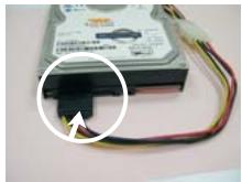
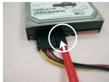
Please connect SATA power cable 1x4-pin end (White) to the power supply 1x4-pin cable.

Connect SATA data cable to the motherboard's SATAI connector.
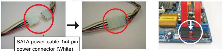

Connect SATA 15-pin power cable connector (Black) end to SATA / SATAII HDD.

Connect SATA data cable to the SATA / SATAII HDD.
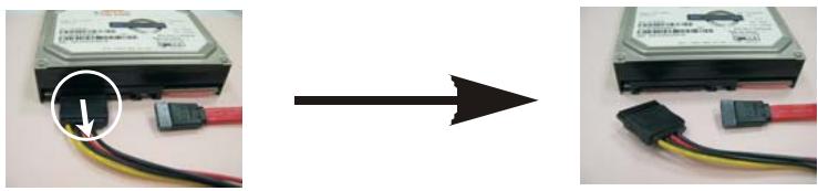
How to Hot Unplug a SATA / SATAll HDD:
Points of attention, before you process the Hot Unplug:
Please do follow below instruction sequence to process the Hot Unplug, improper procedure will cause the SATA / SATAII HDD damage and data loss.

Unplug SATA data cable from SATA / SATAll HDD side.
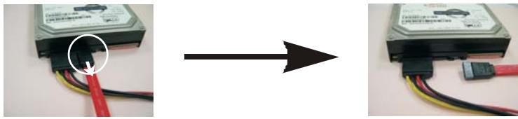

Unplug SATA 15-pin power cable connector (Black) from SATA / SATAII HDD side.
2.14 Driver Installation Guide
To install the drivers to your system, please insert the support CD to your optical drive first. Then, the drivers compatible to your system can be auto-detected and listed on the support CD driver page. Please follow the order from up to bottom side to install those required drivers. Therefore, the drivers you install can work properly.
2.15 Installing Windows XP / XP 64-bit / Vista™ / Vista™ 64-bit Without RAID Functions
If you want to install Windows® XP, Windows® XP 64-bit, Windows® Vista™ or Windows® Vista™ 64-bit on your SATA/ SATAII HDDs without RAID functions, please follow below procedures according to the OS you install.
2.15.1 Installing Windows XP / XP 64-bit Without RAID Functions
If you want to install Windows XP / Windows XP 64-bit on your SATA / SATAII HDDs without RAID functions, please follow below steps.
Using SATA / SATAAll HDDs and eSATAI devices with NCQ and Hot Plug functions
STEP 1: Set Up BIOS.
A. Enter BIOS SETUP UTILITY Advanced screen IDE Configuration.
B. Set the "SATA Operation Mode" option to [non-RAID].
STEP 2: Make a SATA / SATAll driver diskette.
A. Insert the ASRock Support CD into your optical drive to boot your system.
B. During POST at the beginning of system boot-up, press
C. When you see the message on the screen, "Generate Serial ATA driver diskette [YN]?", press
D. Then you will see these messages,
Please choose:
- Generate AHCI Driver diskette for WindowsXP/XP64
- Generate RAID Driver diskette for WindowsXP
- Generate RAID Driver diskette for WindowsXP64
4.Exit
Reboot system now
Press any key to continue
Please insert a floppy diskette into the floppy drive. Select your required item on the list according to the mode you choose and the OS you install. Then press any key.
E. The system will start to format the floppy diskette and copy SATA / SATAI drivers into the floppy diskette.
STEP 3: Set Up BIOS.
Please follow step 1 to set up the BIOS option "SATA Operation Mode" to [AHCI].
STEP 4: Install Windows XP / XP 64-bit OS on your system.
You can start to install Windows XP / XP 64-bit on your system. At the beginning of Windows setup, press F6 to install a third-party AHCI driver. When prompted, insert the SATA/SATAI driver diskette containing the NVIDIA AHCI driver. After reading the floppy disk, the drivers will be presented. Select the driver to install according to the OS you install. The drivers are as below:
A. NVIDIA nForce Storage Controller (required) Windows XP
B. NVIDIA nForce Storage Controller (required) Windows XP64
Please select A for Windows® XP in AHCI mode. Please select B for Windows® XP 64-bit in AHCI mode.
Using SATA / SATAII HDDs and eSATAI devices without NCQ and Hot Plug functions
STEP 1: Set Up BIOS.
A. Enter BIOS SETUP UTILITY Advanced screen IDE Configuration.
B. Set the "SATA Operation Mode" option to [non-RAID].
STEP 2: Install Windows XP / XP 64-bit OS on your system.
2.15.2 Installing Windows® Vista™ / Vista™ 64-bit Without RAID Functions
If you want to install Windows® Vista™ / Windows® Vista™ 64-bit on your SATA/ SATAAll HDDs without RAID functions, please follow below steps.
Using SATA / SATAII HDDs and eSATAII devices with NCQ and Hot Plug functions
STEP1: Set Up BIOS.
A. Enter BIOS SETUP UTILITY Advanced screen IDE Configuration.
B. Set the "SATA Operation Mode" option to [AHCI].
STEP 2: Install Windows Vista™ / Vista™ 64-bit OS on your system.
Insert the Windows® Vista™ / Windows® Vista™ 64-bit optical disk into the optical drive to boot your system, and follow the instruction to install Windows® Vista™ / Windows® Vista™ 64-bit OS on your system. When you see “Where do you want to install Windows? ” page, please insert the ASRock Support CD into your optical drive, and click the “Load Driver” button on the left on the bottom to load the NVIDIA® AHCI drivers. NVIDIA® AHCI drivers are in the following path in our Support CD:
...I386\Vista32_AHCI(ForWindows®Vista™OS)
..\AMD64\Vista64_AHCI (For Windows® Vista™ 64-bit OS)
After that, please insert Windows® Vista™ / Windows® Vista™ 64-bit optical disk into the optical drive again to continue the installation.
Using SATA / SATAII HDDs and eSATAII devices without NCQ and Hot Plug functions
STEP 1: Set Up BIOS.
A. Enter BIOS SETUP UTILITY Advanced screen IDE Configuration.
B. Set the "SATA Operation Mode" option to [non-RAID].
STEP 2: Install Windows® Vista™ / Vista™ 64-bit OS on your system.
2.16 Installing Windows XP / XP 64-bit / Vista™ / Vista™ 64-bit With RAID Functions
If you want to install Windows® XP, Windows® XP 64-bit, Windows® Vista™ or Windows® Vista™ 64-bit on your SATA / SATAII HDDs with RAID functions, please follow below procedures according to the OS you install.
2.16.1 Installing Windows XP / XP 64-bit With RAID Functions
If you want to install Windows XP / Windows XP 64-bit on your SATA / SATAII HDDs with RAID functions, please follow below steps.
STEP 1: Set Up BIOS.
A. Enter BIOS SETUP UTILITY Advanced screen IDE Configuration.
B. Set the "SATA Operation Mode" option to [non-RAID].
STEP 2: Make a SATA / SATAll driver diskette.
Please make a SATA / SATAII driver diskette by following section 2.15.1 step 2 on page 41.

If you want to enable Hot Plug function on eSATAI ports but you install OS on IDE HDD, please skip step 1 and 2.
STEP 3: Set Up BIOS.
Please follow step 1 to set up the BIOS option "SATA Operation Mode" to [RAID].
STEP 4: Use "RAID Installation Guide" to set RAID configuration.
Before you start to configure RAID function, you need to check the RAID installation guide in the Support CD for proper configuration. Please refer to the BIOS RAID installation guide part of the document in the following path in the Support CD:
...RAID Installation Guide
STEP 5: Install Windows XP / XP 64-bit OS on your system.
You can start to install Windows® XP / Windows® XP 64-bit OS on your system. At the beginning of Windows® setup, press F6 to install a third-party RAID driver. When prompted, insert the SATA / SATAAll driver diskette containing the NVIDIA® RAID driver. After reading the floppy disk, the drivers will be presented. Select the drivers to install. The drivers are as below:
A. NVIDIA RAID Driver (required)
B. NVIDIA nForce Storage Controller (required)
Please select A and B for Windows® XP / XP 64-bit in RAID mode. (There are two RAID drivers needed for RAID mode, you have to select them separately. Please specify the first RAID driver and then specify again for the second one.)
NOTE. If you install Windows XP / Windows XP 64-bit on IDE HDDs and want to manage (create, convert, delete, or rebuild) RAID functions on SATA / SATAll HDDs, you still need to set up "SATA Operation Mode" to [RAID] in BIOS first. Then, please set the RAID configuration by using the Windows RAID installation guide part of the document in the following path in the Support CD: ..\RAID Installation Guide
2.16.2 Installing Windows® Vista™ / Vista™ 64-bit With RAID Functions
If you want to install Windows® Vista™ / Windows® Vista™ 64-bit on your SATA/ SATAAll HDDs with RAID functions, please follow below steps.
STEP 1: Set Up BIOS.
A. Enter BIOS SETUP UTILITY Advanced screen IDE Configuration.
B. Set the "SATA Operation Mode" option to [RAID].
STEP 2: Use "RAID Installation Guide" to set RAID configuration.
Before you start to configure RAID function, you need to check the RAID installation guide in the Support CD for proper configuration. Please refer to the BIOS RAID installation guide part of the document in the following path in the Support CD:
...RAID Installation Guide
STEP 3: Install Windows® Vista™ / Vista™ 64-bit OS on your system.
Insert the Windows® Vista™ / Windows® Vista™ 64-bit optical disk into the optical drive to boot your system, and follow the instruction to install Windows® Vista™ / Windows® Vista™ 64-bit OS on your system. When you see “Where do you want to install Windows? ” page, please insert the ASRock Support CD into your optical drive, and click the “Load Driver” button on the left on the bottom to load the NVIDIA® RAID drivers. NVIDIA® RAID drivers are in the following path in our Support CD:
...I386\Vista32 RAID (For Windows® Vista™ OS)
..\AMD64\Vista64 RAID (For Windows® Vista™ 64-bit OS)
After that, please insert Windows® Vista™ / Windows® Vista™ 64-bit optical disk into the optical drive again to continue the installation.
NOTE. If you install Windows® Vista™ / Windows® Vista™ 64-bit on IDE HDDs and want to manage (create, convert, delete, or rebuild) RAID functions on SATA / SATAII HDDs, you still need to set up "SATA Operation Mode" to [RAID] in BIOS first. Then, please set the RAID configuration by using the Windows RAID installation guide in the following path in the Support CD: ..\RAID Installation Guide
2.17 Untied Overclocking Technology
This motherboard supports Untied Overclocking Technology, which means during overclocking, FSB enjoys better margin due to fixed PCI / PCIE buses. Before you enable Untied Overclocking function, please enter "Overclock Mode" option of BIOS setup to set the selection from [Auto] to [CPU, PCIE, Async]. Therefore, CPU FSB is untied during overclocking, but PCI / PCIE buses are in the fixed mode so that FSB can operate under a more stable overclocking environment.

Please refer to the warning on page 8 for the possible overclocking risk before you apply Untied Overclocking Technology.
3. BIOS SETUP UTILITY
3.1 Introduction
This section explains how to use the BIOS SETUP UTILITY to configure your system. The Flash Memory on the motherboard stores the BIOS SETUP UTILITY. You may run the BIOS SETUP UTILITY when you start up the computer. Please press
If you wish to enter the BIOS SETUP UTILITY after POST, restart the system by pressing <Ctrl> + <Alt> + <Delete> , or by pressing the reset button on the system chassis. You may also restart by turning the system off and then back on.

Because the BIOS software is constantly being updated, the following BIOS setup screens and descriptions are for reference purpose only, and they may not exactly match what you see on your screen.
3.1.1 BIOS Menu Bar
The top of the screen has a menu bar with the following selections:
Main To set up the system time/date information
Advanced To set up the advanced BIOS features
H/W Monitor To display current hardware status
Boot To set up the default system device to locate and load the Operating System
Security To set up the security features
Exit To exit the current screen or the BIOS SETUP UTILITY
Use <> key or <> key to choose among the selections on the menu bar, and then press
3.1.2 Navigation Keys
Please check the following table for the function description of each navigation key.
Navigation Key(s) Function Description
| ← / → | Moves cursor left or right to select Screens |
| ↑ / ↓ | Moves cursor up or down to select items |
| + / - | To change option for the selected items |
| <Enter> | To bring up the selected screen |
| <F1> | To display the General Help Screen |
| <F9> | To load optimal default values for all the settings |
| <F10> | To save changes and exit the BIOS SETUP UTILITY |
| <ESC> | To jump to the Exit Screen or exit the current screen |
3.2 Main Screen
When you enter the BIOS SETUP UTILITY, the Main screen will appear and display the system overview.
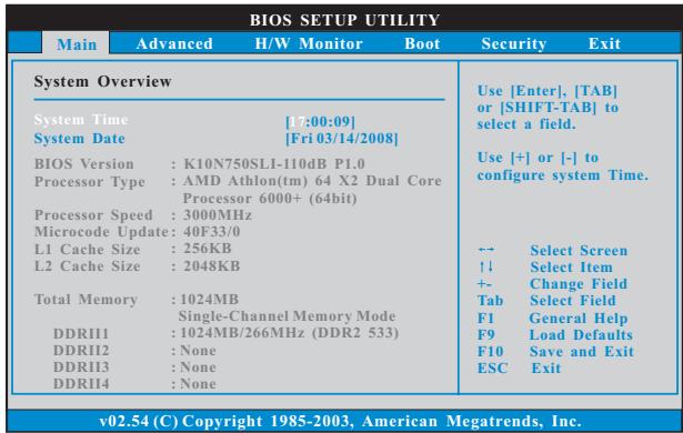
System Time [Hour:Minute:Second]
Use this item to specify the system time.
System Date [Day Month/Date/Year]
Use this item to specify the system date.
3.3 Advanced Screen
In this section, you may set the configurations for the following items: CPU Configuration, Chipset Configuration, ACPI Configuration, IDE Configuration, PCIPnP Configuration, Floppy Configuration, SuperIO Configuration, and USB Configuration.
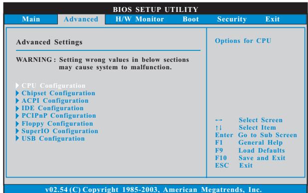

Setting wrong values in this section may cause the system to malfunction.
3.3.1 CPU Configuration
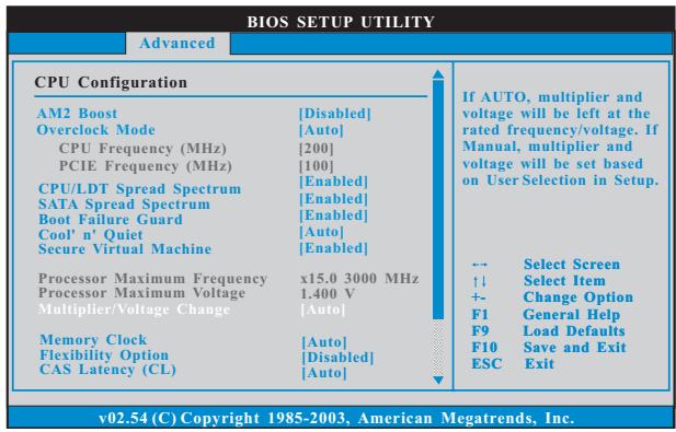
AM2 Boost
If you set this option to [Enabled], you will enable ASRock AM2 Boost function, which will improve the memory performance. The default value is [Disabled]. Please refer to caution 17 on page 10 for details.
Overclock Mode
Use this to select Overclock Mode. The default value is [Auto]. Configuration options: [Auto], [CPU, PCIE, Sync.] and [CPU, PCIE, Async.].
CPU Frequency (MHz)
Use this option to adjust CPU frequency.
PCIE Frequency (MHz)
Use this option to adjust PCIE frequency.
CPU/LDT Spread Spectrum
This feature will be set to [Enabled] as default. Configuration options: [Disabled] and [Enabled].
SATA Spread Spectrum
This feature will be set to [Enabled] as default. Configuration options: [Disabled] and [Enabled].
Boot Failure Guard
Enable or disable the feature of Boot Failure Guard.
Cool 'n' Quiet
Use this item to enable or disable AMD's Cool 'n' Quiet™ technology. The default value is [Auto]. Configuration options: [Auto], [Enabled] and [Disabled]. If you install Windows® Vista™ and want to enable this function, please set this item to [Enabled]. Please note that enabling this function may reduce CPU voltage and memory frequency, and lead to system stability or compatibility issue with some memory modules or power supplies. Please set this item to [Disable] if above issue occurs.
Secure Virtual Machine
This option appears only when you adopt AM2 CPU. When this option is set to [Enabled], a VMM (Virtual Machine Architecture) can utilize the additional hardware capabilities provided by AMD-V. The default value is [Enabled]. Configuration options: [Enabled] and [Disabled].
Processor Maximum Frequency
It will display Processor Maximum Frequency for reference.
North Bridge Maximum Frequency
This option appears only when you adopt Phenom CPU. It will display North Bridge Maximum Frequency for reference.
Processor Maximum Voltage
It will display Processor Maximum Voltage for reference.
Multiplier/Voltage Change
This item is set to [Auto] by default. If it is set to [Manual], you may adjust the value of Processor Frequency and Processor Voltage. However, it is recommended to keep the default value for system stability.
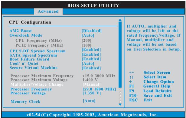
Processor Frequency
This option appears only when you adopt AM2 CPU. This item will show when "Multiplier/Voltage Change" is set to [Manual]; otherwise, it will be hidden. The range of the value depends on the CPU you adopt on this motherboard. However, for system stability, it is not recommended to adjust the value of this item.
Processor Voltage
This option appears only when you adopt AM2 CPU. This item will show when "Multiplier/Voltage Change" is set to [Manual]; otherwise, it will be hidden. The range of the value depends on the CPU you adopt on this motherboard. However, for safety and system stability, it is not recommended to adjust the value of this item.
Processor Target Frequency
This option appears only when you adopt Phenom CPU. This item will show when "Multiplier/Voltage Change" is set to [Manual]; otherwise, it will be hidden. The range of the value depends on the CPU you adopt on this motherboard. However, for system stability, it is not recommended to adjust the value of this item.
North Bridge Target Frequency
This option appears only when you adopt Phenom CPU. This item will show when "Multiplier/Voltage Change" is set to [Manual]; otherwise, it will be hidden. The range of the value depends on the CPU you adopt on this motherboard. However, for safety and system stability, it is not recommended to adjust the value of this item.
CPU Frequency Multiplier
This option appears only when you adopt Phenom CPU. However, for safety and system stability, it is not recommended to adjust the value of this item.
CPU Frequency Divider
This option appears only when you adopt Phenom CPU. However, for safety and system stability, it is not recommended to adjust the value of this item.
CPU Voltage
This option appears only when you adopt Phenom CPU. It allows you to adjust the value of CPU voltage. However, for safety and system stability, it is not recommended to adjust the value of this item.
NB Frequency Multiplier
This option appears only when you adopt Phenom CPU. However, for safety and system stability, it is not recommended to adjust the value of this item.
NB Voltage
This option appears only when you adopt Phenom CPU. It allows you to adjust the value of NB voltage. However, for safety and system stability, it is not recommended to adjust the value of this item.
Memory Clock
This item can be set by the code using [Auto]. You can set one of the standard values as listed: [200 MHz (DDR2 400)], [266 MHz (DDR2 533)],
[333 MHz (DDR2 667)] and [400MHz (DDR2 800)]. If you adopt Phenom CPU, there is one more option: [533MHz (DDR2 1066)].
Flexibility Option
The default value of this option is [Disabled]. It will allow better tolerance for memory compatibility when it is set to [Enabled].
CAS Latency (CL)
Use this item to adjust the means of memory accessing. Configuration options: [Auto], [3CLK], [4CLK], [5CLK] and [6CLK]. The default value is [Auto].
TRCD
Use this to adjust TRCD values. Configuration options: [Auto], [3CLK], [4CLK], [5CLK] and [6CLK]. The default value is [Auto].
TRP
Use this to adjust TRP values. Configuration options: [Auto], [3CLK], [4CLK], [5CLK] and [6CLK]. The default value is [Auto].
TRTP
Use this to adjust TRTP values. Configuration options: [Auto], [2-4CLK] and [3-5CLK]. The default value is [Auto].
TRAS
Use this to adjust TRAS values. Configuration options: [Auto], [5CLK] to [18CLK]. The default value is [Auto].
TRRD
Use this to adjust TRRD values. Configuration options: [Auto], [2CLK], [3CLK], [4CLK] and [5CLK]. The default value is [Auto].
TRC
Use this to adjust TRC values. Configuration options: [11CLK] to [25CLK]. The default value is [Auto].
TWR
Use this to adjust TWR values. Configuration options: [Auto], [3CLK], [4CLK], [5CLK] and [6CLK]. The default value is [Auto].
TWTR
Use this to adjust TWTR values. Configuration options: [Auto], [1CLK], [2CLK] and [3CLK]. The default value is [Auto].
TRWTTO
This option appears only when you adopt AM2 CPU. Use this to adjust TRWTTD values. Configuration options: [Auto], [2CLK], [3CLK], [4CLK], [5CLK], [6CLK], [7CLK], [8CLK] and [9CLK]. The default value is [Auto].
TWRRD
This option appears only when you adopt AM2 CPU. Use this to adjust TWRRD values. Configuration options: [Auto], [0CLK], [1CLK], [2CLK] and [3CLK]. The default value is [Auto].
TWRWR
This option appears only when you adopt AM2 CPU. Use this to adjust TWRWR values. Configuration options: [Auto], [1CLK], [2CLK] and [3CLK]. The default value is [Auto].
TRDRD
This option appears only when you adopt AM2 CPU. Use this to adjust TRWTTD values. Configuration options: [Auto], [2CLK], [3CLK], [4CLK] and [5CLK]. The default value is [Auto].
MA Timing
Use this to adjust values for MA timing. Configuration options: [Auto], [2T], [1T]. The default value is [Auto].
Addr/Cmd Fine Delay
Use this to adjust values for Addr/Cmd Fine Delay feature. Configuration options: [Auto], [No Delay], [1/64CLK] to [31/64CLK]. The default value is [Auto].
CS/ODT Fine Delay
Use this to adjust values for CS/ODT Fine Delay feature. Configuration options: [Auto], [No Delay], [1/64CLK] to [31/64CLK]. The default value is [Auto].
Bank Interleaving
Interleaving allows memory accesses to be spread out over banks on the same node, or across nodes, decreasing access contention.
3.3.2 Chipset Configuration
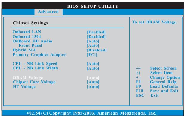
Onboard LAN
This allows you to enable or disable the onboard LAN feature.
Onboard IEEE 1394
This allows you to enable or disable the onboard IEEE 1394 feature.
OnBoard HD Audio
Select [Auto], [Enabled] or [Disabled] for the onboard HD Audio feature. If you select [Auto], the onboard HD Audio will be disabled when PCI Sound Card is plugged.
Front Panel
Select [Auto], [Enabled] or [Disabled] for the onboard HD Audio Front Panel.
Hybrid SLI
Adjust this item if you want this motherboard to support Hybrid SLITM function. This item is available only when the total capacity of the memory module you adopt is above 1GB. Configuration options: [Disabled], [256MB] and [512MB]. The default value is [Disabled].
Primary Graphics Adapter
This item will switch the PCI Bus scanning order while searching for video card. It allows you to select the type of Primary VGA in case of multiple video controllers. The default value of this feature is [PCI]. Configuration options: [PCI] and [PCI Express].
CPU - NB Link Speed
This feature allows you selecting CPU to NB link frequency. Configuration options: [Auto], [200 MHz], [400 MHz], [600 MHz], [800 MHz] and [1000 MHz]. The configuratopn options depend on the CPU you adopt. If you adopt Phenom CPU, the configuration options are: [Auto], [200 MHz], [400 MHz], [600 MHz], [800 MHz], [1000 MHz], [1800 MHz], [2000 MHz], [2200 MHz], [2400 MHz] and [2600 MHz].
CPU - NB Link Width
This feature allows you selecting CPU to NB link width. Configuration options: [Auto], [8 Bit] and [16 Bit].
DRAM Voltage
Use this to select DRAM voltage. Configuration options: [Auto], [1.80V], [1.85V], [1.90V], [1.95V], [2.00V], [2.05V], [2.15V], [2.20V], [2.30V], [2.35V], [2.40V], [2.45V], [2.55V], [2.60V], [2.65V] and [2.70V]. The default value is [Auto].
Chipset Core Voltage
Use this to select chipset core voltage. Configuration options: [Auto], [1.10V], [1.15V], [1.20V] and [1.25V]. The default value is [Auto].
HT Voltage
Use this to select HT voltage. Configuration options: [Auto], [1.20V], [1.25V], [1.30V] and [1.35V]. The default value is [Auto].
3.3.3 ACPI Configuration
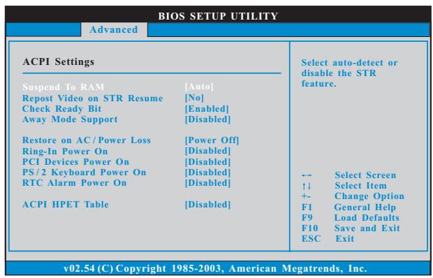
Suspend to RAM
Use this item to select whether to auto-detect or disable the Suspend-to-RAM feature. Select [Auto] will enable this feature if the OS supports it. If you set this item to [Disabled], the function "Repost Video on STR Resume" will be hidden.
Repost Video on STR Resume
This feature allows you to repost video on STR resume. (STR refers to suspend to RAM.)
Check Ready Bit
Use this item to enable or disable the feature Check Ready Bit.
Away Mode Support
Use this item to enable or disable Away Mode support under Windows® XP Media Center OS. The default value is [Disabled].
Restore on AC/Power Loss
This allows you to set the power state after an unexpected AC/power loss. If [Power Off] is selected, the AC/power remains off when the power recovers. If [Power On] is selected, the AC/power resumes and the system starts to boot up when the power recovers.
Ring-In Power On
Use this item to enable or disable Ring-In signals to turn on the system from the power-soft-off mode.
PCI Devices Power On
Use this item to enable or disable PCI devices to turn on the system from the power-soft-off mode.
PS/2 Keyboard Power On
Use this item to enable or disable PS/2 keyboard to turn on the system from the power-soft-off mode.
RTC Alarm Power On
Use this item to enable or disable RTC (Real Time Clock) to power on the system.
ACPI HPET Table
Use this item to enable or disable ACPI HPET Table. The default value is [Disabled]. Please set this option to [Enabled] if you plan to use this motherboard to submit Windows® Vista™ certification.
3.3.4IDE Configuration
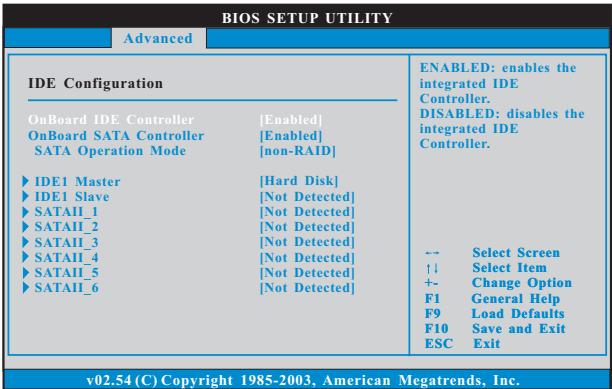
OnBoard IDE Controller
Use this item to enable or disable the "OnBoard IDE Controller" feature.
OnBoard SATA Controller
Use this item to enable or disable the "OnBoard SATA Controller" feature.
SATA Operation Mode
Use this item to adjust SATA Operation Mode. The default value of this option is [non-RAID]. If you want to operate RAID function on SATA / SATAII HDDs, please select [RAID]. If you want to enable eSATAII function, please select [RAID] or [AHCI]. Configuration options: [RAID], [non-RAID] and [AHCI].
- If you select [RAID] mode, SATA / SATAAll HDDs can not be accessed until you finish configuring RAID functions in NVIDIA BIOS / Windows RAID Utility.
- If you install OS on SATA / SATAII HDDs, please do not change the setting of this item after OS installation.
- If you install SATA / SATAAll device on eSATAI port and plan to make a floppy image or use Ghost under DOS (Disk Operating System), please set this option to [non-RAID].
IDE Device Configuration
You may set the IDE configuration for the device that you specify. We will use the "IDE1 Master" as the example in the following instruction, which can be applied to the configurations of "IDE1 Slave" as well.
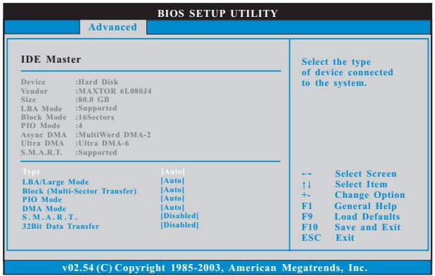
TYPE
Use this item to configure the type of the IDE device that you specify.
Configuration options: [Not Installed], [Auto], [CD/DVD], and [ARMD].
[Not Installed]: Select [Not Installed] to disable the use of IDE device.
[Auto]: Select [Auto] to automatically detect the hard disk drive.

After selecting the hard disk information into BIOS, use a disk utility, such as FDISK, to partition and format the new IDE hard disk drives. This is necessary so that you can write or read data from the hard disk. Make sure to set the partition of the Primary IDE hard disk drives to active.
[CD/DVD]:This is used for IDE CD/DVD drives.
[ARMD]: This is used for IDE ARMD (ATAPI Removable Media Device), such as MO.
LBA/Large Mode
Use this item to select the LBA/Large mode for a hard disk >512 MB under DOS and Windows; for Netware and UNIX user, select [Disabled] to disable the LBA/Large mode.
Block (Multi-Sector Transfer)
The default value of this item is [Auto]. If this feature is enabled, it will enhance hard disk performance by reading or writing more data during each transfer.
PIO Mode
Use this item to set the PIO mode to enhance hard disk performance by optimizing the hard disk timing.
DMA Mode
DMA capability allows the improved transfer-speed and data-integrity for compatible IDE devices.
S.M.A.R.T.
Use this item to enable or disable the S.M.A.R.T. (Self-Monitoring, Analysis, and Reporting Technology) feature. Configuration options: [Disabled], [Auto], [Enabled].
32Bit Data Transfer
Use this item to enable 32-bit access to maximize the IDE hard disk data transfer rate.
3.3.5 PCIPnP Configuration
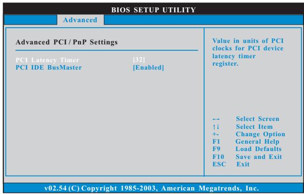

Setting wrong values in this section may cause the system to malfunction.
PCI Latency Timer
The default value is 32. It is recommended to keep the default value unless the installed PCI expansion cards' specifications require other settings.
PCI IDE BusMaster
Use this item to enable or disable the PCI IDE BusMaster feature.
3.3.6Floppy Configuration
In this section, you may configure the type of your floppy drive.
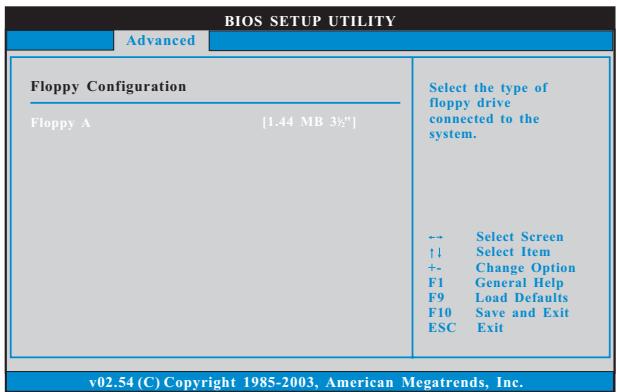
3.3.7 Super IO Configuration
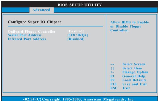
OnBoard Floppy Controller
Use this item to enable or disable floppy drive controller.
Serial Port Address
Use this item to set the address for the onboard serial port or disable it.
Configuration options: [Disabled], [3F8 / IRQ4], [2F8 / IRQ3], [3E8 / IRQ4], [2E8 / IRQ3].
Infrared Port Address
Use this item to set the address for the onboard infrared port or disable it.
Configuration options: [Disabled], [2F8 / IRQ3], and [2E8 / IRQ3]. If you plan to use ASRock DeskExpress on this motherboard, please keep this item on [Disabled] option.
3.3.8 USB Configuration
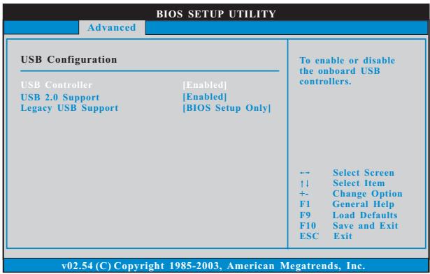
USB Controller
Use this item to enable or disable the use of USB controller.
USB 2.0 Support
Use this item to enable or disable the USB 2.0 support.
Legacy USB Support
Use this option to select legacy support for USB devices. There are four configuration options: [Enabled], [Auto], [Disabled] and [BIOS Setup Only]. The default value is [BIOS Setup Only]. Please refer to below descriptions for the details of these four options:
[Enabled] - Enables support for legacy USB.
[Auto] - Enables legacy support if USB devices are connected.
[Disabled] - USB devices are not allowed to use under legacy OS and BIOS setup when [Disabled] is selected. If you have USB compatibility issue, it is recommended to select [Disabled] to enter OS.
[BIOS Setup Only] - USB devices are allowed to use only under BIOS setup and Windows / Linux OS.
3.4 Hardware Health Event Monitoring Screen
In this section, it allows you to monitor the status of the hardware on your system, including the parameters of the CPU temperature, motherboard temperature, CPU fan speed, chassis fan speed, and the critical voltage.
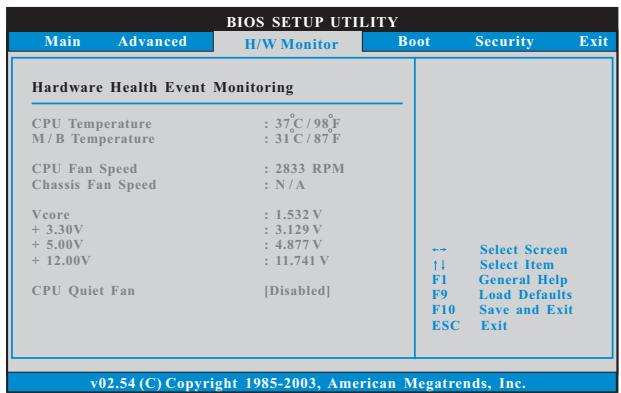
CPU Quiet Fan
This item allows you to identify the temperature of CPU fan. If you set this option as [Disabled], the CPU fan will operate in full speed. If you set this option as [Enabled], you will find the items "Target CPU Temperature" and "Target Fan Speed" appear to allow you adjusting them. The default value is [Disabled]. You are allowed to enable this function only when you install 4-pin CPU fan.
Target CPU Temperature
The target temperature will be between 45^ / 113^ and 65^ / 149^ . The default value is [50^ / 122^] .
Target Fan Speed
Use this option to set the target fan speed. You can freely adjust the target fan speed according to the target CPU temperature that you choose. Configuration options: [Level 1], [Level 2], [Level 3], [Level 4], [Level 5], [Level 6] [Level 7], [Level 8] and [Level 9].
3.5 Boot Screen
In this section, it will display the available devices on your system for you to configure the boot settings and the boot priority.
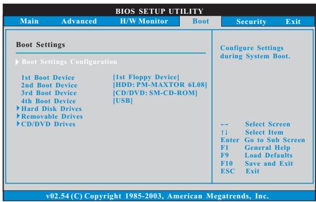
3.5.1 Boot Settings Configuration
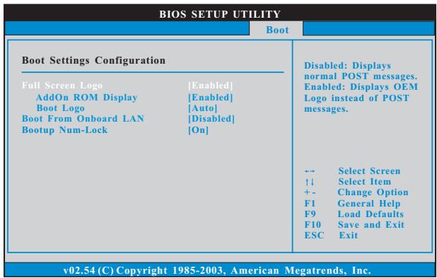
Full Screen Logo
Use this item to enable or disable OEM Logo. The default value is [Enabled].
AddOn ROM Display
Use this option to adjust AddOn ROM Display. If you enable the option
"Full Screen Logo" but you want to see the AddOn ROM information when the system boots, please select [Enabled]. Configuration options: [Enabled] and [Disabled]. The default value is [Enabled].
Boot Logo
Use this option to select logo in POST screen. This option only appears when you enable the option "Full Screen Logo". Configuration options: [Auto],
[Aircraft], [Scenery] and [ASRock]. The default value is [Auto]. Currently, the option [Auto] is set to Aircraft.
Boot From Onboard LAN
Use this item to enable or disable the Boot From Onboard LAN feature.
Boot Up Num-Lock
If this item is set to [On], it will automatically activate the Numeric Lock function after boot-up.
3.6 Security Screen
In this section, you may set or change the supervisor/user password for the system. For the user password, you may also clear it.
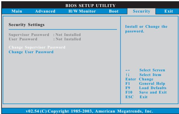
3.7 Exit Screen
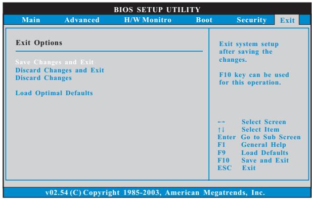
Save Changes and Exit
When you select this option, it will pop-out the following message, "Save configuration changes and exit setup?" Select [OK] to save the changes and exit the BIOS SETUP UTILITY.
Discard Changes and Exit
When you select this option, it will pop-out the following message, "Discard changes and exit setup?" Select [OK] to exit the BIOS SETUP UTILITY without saving any changes.
Discard Changes
When you select this option, it will pop-out the following message, "Discard changes?" Select [OK] to discard all changes.
Load Optimal Defaults
When you select this option, it will pop-out the following message, "Load optimal defaults?" Select [OK] to load the default values for all the setup configurations.
4. Software Support
4.1 Install Operating System
This motherboard supports various Microsoft® Windows® operating systems: XP / XP Media Center / XP 64-bit / Vista™ / Vista™ 64-bit. Because motherboard settings and hardware options vary, use the setup procedures in this chapter for general reference only. Refer to your OS documentation for more information.
4.2 Support CD Information
The Support CD that came with the motherboard contains necessary drivers and useful utilities that enhance the motherboard features.
4.2.1 Running The Support CD
To begin using the support CD, insert the CD into your CD-ROM drive. The CD automatically displays the Main Menu if "AUTORUN" is enabled in your computer. If the Main Menu did not appear automatically, locate and double click on the file "ASSETUP.EXE" from the BIN folder in the Support CD to display the menus.
4.2.2 Drivers Menu
The Drivers Menu shows the available devices drivers if the system detects the installed devices. Please install the necessary drivers to activate the devices.
4.2.3 Utilities Menu
The Utilities Menu shows the applications software that the motherboard supports. Click on a specific item then follow the installation wizard to install it.
4.2.4 Contact Information
If you need to contact ASRock or want to know more about ASRock, welcome to visit ASRock's website at http://www.asrock.com; or you may contact your dealer for further information.