MODE D'EMPLOI GS110TP NETGEAR
GS110TP Hardware Installation Guide
NETGEAR
NETGEAR, Inc.
350 East Plumeria Drive
San Jose, California 95134 USA
202-10596-01
March 2010
v1.0
Trademarks
NETGEAR, the NETGEAR logo, and Auto Uplink are trademarks or registered trademarks of NETGEAR, Inc. Microsoft, Windows, and Windows NT are registered trademarks of Microsoft Corporation. Other brand and product names are registered trademarks or trademarks of their respective holders. Portions of this document are copyright Intoto, Inc.
Statement of Conditions
In the interest of improving internal design, operational function, and/or reliability, NETGEAR reserves the right to make changes to the products described in this document without notice.
NETGEAR does not assume any liability that may occur due to the use or application of the product(s) or circuit layout(s) described herein.
Certificate of the Manufacturer/Importer
It is hereby certified that the GS110TP Smart PoE Switch has been suppressed in accordance with the conditions set out in the BMPT-AmtsblVfg 243/1991 and Vfg 46/1992. The operation of some equipment (for example, test transmitters) in accordance with the regulations may, however, be subject to certain restrictions. Please refer to the notes in the operating instructions.
The Federal Office for Telecommunications Approvals has been notified of the placing of this equipment on the market and has been granted the right to test the series for compliance with the regulations.
Product and Publication Details
Model Number: GS110TP
Publication Date: March 2010
Product Family: Gigabit Advanced Smart Switch
Product Name: GS110TP Smart PoE Switch
Home or Business Product: Business
Language: English
Publication Part Number: 202-10596-01
Publication Version Number: 1.0
Contents
GS110TP Hardware Installation Guide
About This Manual
Conventions, Formats, and Scope
How to Print this Manual vi
Revision History vi
Chapter 1
Introduction
Overview 1-1
Features 1-2
PoE Features 1-3
Green Features 1-3
Package Contents 1-4
Chapter 2
Physical Description
GS110TP Front and Back Panel Configuration 2-1
LED Designations 2-2
Port LEDs 2-2
System LEDs 2-3
Device Hardware Interfaces 2-3
RJ-45 Ports 2-3
Reset Button 2-4
Factory Defaults Button 2-4
Chapter 3
Applications
Desktop Switching 3-1
Chapter 4 Installation
Step 1: Preparing the Site 4-1
Step 2: Installing the Switch 4-2
Installing the Switch on a Flat Surface 4-2
Wall Mounting the Switch 4-2
Step 3: Checking the Installation 4-3
Step 4: Connecting Devices to the Switch 4-3
Step 5: Applying AC Power 4-4
Step 6: Managing the Switch using a Web Browser or the PC Utility 4-4
Appendix A Troubleshooting
Troubleshooting Chart A-1
Additional Troubleshooting A-2
Network Adapter Cards A-2
Configuration A-2
Switch Integrity A-2
Auto-Negotiation A-3
Appendix B Technical Specifications
Index
About This Manual
The NETGEAR® ProSafe™ GS110TP Hardware Installation Guide describes how to install and power on the GS110TP Smart PoE Switch. The information in this manual is intended for readers with intermediate computer and Internet skills.
The conventions, formats, and scope of this manual are described in the following paragraphs:
- Typographical Conventions. This manual uses the following typographical conventions:
| Italic | Emphasis, books, CDs, file and server names, extensions |
| Bold | User input, IP addresses, GUI screen text |
| Fixed | Command prompt, CLI text, code |
| italic | URL links |
- Formats. This manual uses the following formats to highlight special messages:
| → | Note: This format is used to highlight information of importance or special interest. |
| Tip: This format is used to highlight a procedure that will save time or resources. |
| ! | Warning: Ignoring this type of note may result in a malfunction or damage to the equipment. |

Danger: This is a safety warning. Failure to take heed of this notice may result in personal injury or death.
- Scope. This manual is written for the GS110TP Smart PoE Switch according to these specifications:
Product Version GS110TP Smart PoE Switch
Manual Publication Date March 2010

Note: Product updates are available on the NETGEAR, Inc. website at http://kbserver.netgear.com/products/GS110TP.asp.
How to Print this Manual
To print this manual, use the Complete PDF Manual link at the top left of any page.
- Click the Complete PDF Manual link at the top left of any page in the manual. The PDF version of the complete manual opens in a browser window.
- Click the print icon in the upper left of the window.

Tip: If your printer supports printing two pages on a single sheet of paper, you can save paper and printer ink by selecting this feature.
Revision History
| Part Number | Version Number | Date | Description |
| 202-10596-01 | 1.0 | March 2010 | Initial release |
Chapter 1 Introduction
Congratulations on the purchase of your NETGEAR GS110TP Smart PoE Switch. The GS110TP Smart PoE Switch is a supplement to the Gigabit Advanced Smart Switch family. Available as a desktop or wall-mountable switch, the GS110TP Smart PoE Switch is not intended to be rackmountable. The GS110TP is a PoE-supportable, low-port switch with two fiber uplinks included.
This chapter serves as an introduction to the GS110TP Smart PoE Switch and provides the following information:
Overview
- Features
Package Contents
Overview
This Installation Guide is for the NETGEAR GS110TP Smart PoE Switch. This product offers support for eight 10/100/1000 Mbps autosensing and two 1000M SFP Gigabit Ethernet switching ports.
Using Gigabit ports, high-speed connections can be made to a server or network backbone. For example:
- Linking to high-speed servers
Providing 10/100/1000 Mbps copper connectivity
The GS110TP Smart PoE Switch also provides the benefit of administrative management with a complete package of features for the observation, configuration, and control of the network. With a Web-based Graphical User Interface (GUI), the switch's many capabilities can be viewed and used in a simple and intuitive manner. The switch's management features include configuration for port and switch information, VLAN for traffic control, port trunking for increased bandwidth, and Class of Service (CoS) for traffic prioritization. These features provide better understanding and control of the network. Initial discovery of the switch on the network requires the Netgear Smart Control Center program, a utility that runs on a PC.
The GS110TP Smart PoE Switch is a free-standing switch. It is IEEE-compliant and offers low latency for high-speed networking. All ports can automatically negotiate to the highest speed. This capability makes the switch ideal for environments that have a mix of Ethernet, Fast Ethernet, or Gigabit Ethernet devices. In addition, all RJ-45 ports operate in half-duplex or full-duplex mode. The maximum segment length is 328 feet (100 meters) over Category 5 Unshielded Twisted-Pair (UTP) cable.
Features
The following list identifies the key features of the GS110TP Smart PoE Switch:
Eight RJ-45 10/100/1000 Mbps autosensing Gigabit Ethernet switching ports.
- Two 1000M SFP Gigabit Ethernet switching ports.
Full NETGEAR Smart Switch functionality.
Full compatibility with IEEE standards:
Standard NETGEAR 1xx series chassis.
- NETGEAR Green product features.
External 48V/1.25A PA.
PoE Features
The GS110TP Smart PoE Switch supports IEEE 802.3af PSE features:
Ports 1 through 8 support IEEE 802.3af, Alternative A (MDI-X).
- PoE is enabled by default.
Green Features
The GS110TP Smart PoE Switch supports the following power-saving features:
- The power consumption automatically adjusts based on the RJ-45 cable length.
Each port is configured to power down automatically when the port link is down.
Package Contents
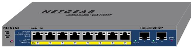
Figure 1-1 shows the package contents of the NETGEAR GS110TP Smart PoE Switch.
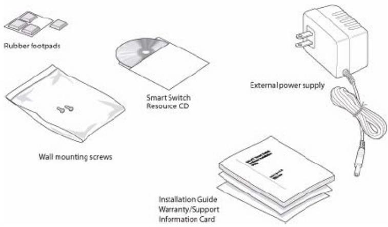
Verify that the package contains the following:
- NETGEAR GS110TP Smart PoE Switch
Rubber footpads for tabletop installation
- Wall mounting screws (2)
External power adapter
Installation guide
- Smart Switch Resource CD with Netgear Smart Control Center and User's manual If any item is missing or damaged, contact the place of purchase immediately.
This chapter describes the NETGEAR GS110TP Smart PoE Switch hardware features. Topics include:
GS110TP Front and Back Panel Configuration
LED Designations
Device Hardware Interfaces
GS110TP Front and Back Panel Configuration
The GS110TP Smart PoE Switch has eight 10/100/1000 Mbps autosensing and two 1000 Mbps SFP Gigabit Ethernet switching ports. Each RJ-45 port is capable of sensing the line speed and negotiating the duplex mode with the link partner automatically.
Figure 2-1 illustrates the front panel of the NETGEAR GS110TP Smart PoE Switch:
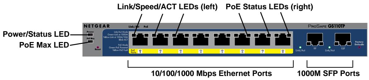
The front panel contains the following:
Eight RJ-45 connectors for 10/100/1000 Mbps autosensing Gigabit Ethernet switching ports
- Two 1000M SFP Gigabit Ethernet switching ports
- Reset button to restart the device
- Recessed default reset button to restore the device back to the factory defaults
- Link, Speed, and Activity LEDs for each port
Power and Status LED
- PoE Max LED
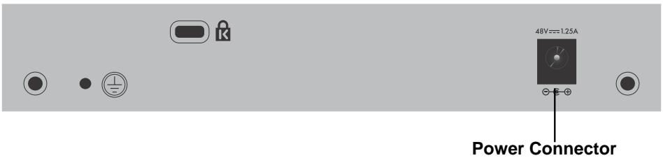
Figure 2-2 illustrates the NETGEAR GS110TP Smart PoE Switch back panel.
The back panel contains the following:
A DC input for the supplied 48V/1.25A external power adapter
LED Designations
Port LEDs
The following table describes the RJ-45 and SFP port LED designations. There are two LEDs for each RJ-45 port. Each SFP port has its own indication LED.
Table 2-1. Port LEDs
| LED | Designation |
| Speed/Link/Activity
(Left LED on each RJ-45 port) | • Off = No link is established on the port.
• Solid Green = A valid 1000 Mbps link is established on the port.
• Flashing Green = Packet transmission or reception is occurring on the port at 1000 Mbps.
• Solid Yellow = A valid 10/100 Mbps link is established on the port.
• Flashing Yellow = Packet transmission or reception is occurring on the port at 10/100 Mbps. |
| PoE Status
(Right LED on each RJ-45 port) | ·Off = No PoE powered device (PD) connected.
·Solid Green = The PoE PD is connected and the port is supplying power successfully.
·Flashing Yellow = One of the following failures resulted in stopping power to that port:
- Short circuit on PoE power circuit.
- PoE power demand exceeds power available.
- PoE current exceeds PD's classification.
- Out of proper voltage band (44 ~ 57 VDC). |
| SFP Port Indicate LED | ·Off = No link is established on the port.
·Solid Green = A valid link is established on the port.
·Flashing Green = Packet transmission or reception is occurring on the port. |
System LEDs
The following table describes the system LED designations.
Table 2-2. System LEDs
| LED | Designation |
| Power/Status LED | ·Solid Green = Power is supplied to the switch and the switch is operating normally.
·Solid Yellow = The switch is booting.
·Off = Power is disconnected. |
| PoE MAX LED | ·Off = There is at least 7W of PoE power available for another device.
·Solid Yellow = Less than 7W of PoE power is available.
·Flashing Yellow = The PoE MAX LED was active in the previous two minutes. |
Device Hardware Interfaces
RJ-45 Ports
RJ-45 ports are autosensing ports. When inserting a cable into an RJ-45 port, the switch automatically ascertains the maximum speed (10, 100, or 1000 Mbps) and duplex mode (half-duplex or full-duplex) of the attached device. All ports support only unshielded twisted-pair (UTP) cable terminated with an 8-pin RJ-45 plug.
To simplify the procedure for attaching devices, all RJ-45 ports support Auto Uplink. This technology allows attaching devices to the RJ-45 ports with either straight-through or crossover cables. When inserting a cable into the switch's RJ-45 port, the switch automatically:
Senses whether the cable is a straight-through or crossover cable.
- Determines whether the link to the attached device requires a "normal" connection (such as when connecting the port to a PC) or an "uplink" connection (such as when connecting the port to a router, switch, or hub).
- Configures the RJ-45 port to enable communications with the attached device, without requiring user intervention. In this way, the Auto Uplink technology compensates for setting uplink connections, while eliminating concern about whether to use crossover or straight-through cables when attaching devices.
The Smart Switch has a Reset button on the front panel to allow you to manually reboot the switch. This action is equivalent to powering the unit off and back on. The last saved configuration is loaded into the switch as it resets. To operate the Reset button, insert a device such as a paper clip into the opening to press the recessed button. The front-panel LEDs should extinguish and light again as the switch performs its Power On Self Test (POST).
The Smart Switch has a Factory Defaults button on the front panel so that you can remove the current configuration and return the device to its factory settings. When you enable the Factory Defaults button, all settings including the password, VLAN settings, and port configurations are removed. To operate the Factory Defaults button, insert a device such as a paper clip into the opening to press the recessed button for two seconds.
Chapter 3 Applications
Your NETGEAR GS110TP Smart PoE Switch is designed to provide flexibility in configuring your network connections. It can be used as a stand-alone device or with 10 Mbps, 100 Mbps, and 1000 Mbps hubs and switches.
Desktop Switching
The GS110TP Smart PoE Switch can be used as a desktop switch to build a small network that enables users to have 1000 Mbps access to a file server. With full-duplex enabled, the switch port connected to the server or PC can provide 2000 Mbps throughput.
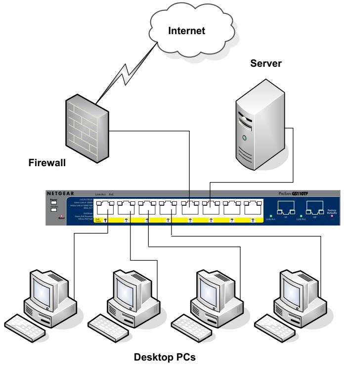
Figure 3-1
Chapter 4 Installation
This chapter describes the installation procedures for your NETGEAR GS110TP Smart PoE Switch. Switch installation involves the following steps:
Step 1: Preparing the Site
Step 2: Installing the Switch
Step 3: Checking the Installation
Step 4: Connecting Devices to the Switch
Step 5: Applying AC Power
Step 6: Managing the Switch using a Web Browser or the PC Utility
Step 1: Preparing the Site
Before you install the switch, ensure the operating environment meets the site requirements in the following table.
Table 4-1. Site Requirements
| Characteristics | Requirements |
| Mounting | • Desktop installations - Provide a flat table or shelf surface.
• Wall-mount installations - Wall-mount: select a location. You also need the mounting screws supplied with your switch. |
| Access | Locate the switch in a position that allows access to the front panel RJ-45 ports, view the front panel LEDs, and access the power connector. |
| Power source | Provide a power adapter (included). Power specifications for the switch are shown in Appendix A . Ensure the AC outlet is not controlled by a wall switch, which can accidentally turn off power to the outlet and the switch. |
| Environmental | • Temperature - Install the switch in a dry area, with ambient temperature between 0 and 50°C (32 and 122°F). Keep the switch away from heat sources such as direct sunlight, warm air exhausts, hot-air vents, and heaters.
• Operating humidity - The installation location should have a maximum relative humidity of 90%, non-condensing.
• Ventilation - Do not restrict airflow by covering or obstructing air inlets on the sides of the switch. Keep at least 2 inches (5.08 centimeters) free on all sides for cooling. Be sure there is adequate airflow in the room or wiring closet where the switch is installed.
• Operating conditions - Keep the switch at least 6 ft. (1.83 m) away from nearest source of electromagnetic noise, such as a photocopy machine. |
Step 2: Installing the Switch
The GS110TP Smart PoE Switch can be used on a flat surface or mounted on the wall.
Installing the Switch on a Flat Surface
The switch ships with four self-adhesive rubber footpads. Stick one rubber footpad on each of the four concave spaces on the bottom of the switch. The rubber footpads cushion the switch against shock/vibrations.
Wall Mounting the Switch
To mount the switch on a wall (optional), install the two provided screws in positions that correspond to the slots on the bottom side of the GS110TP, then mount the switch.
Step 3: Checking the Installation
Before applying power to the switch, perform the following:
- Inspect the equipment thoroughly.
- Verify that all cables are installed correctly.
- Check cable routing to make sure cables are not damaged or creating a safety hazard.
- Ensure all equipment is mounted properly and securely.
Step 4: Connecting Devices to the Switch
The following procedure describes how to connect PCs to the switch's RJ-45 ports. The GS110TP Smart PoE Switch contains Auto Uplink technology, which allows the attaching of devices using either straight-through or crossover cables.
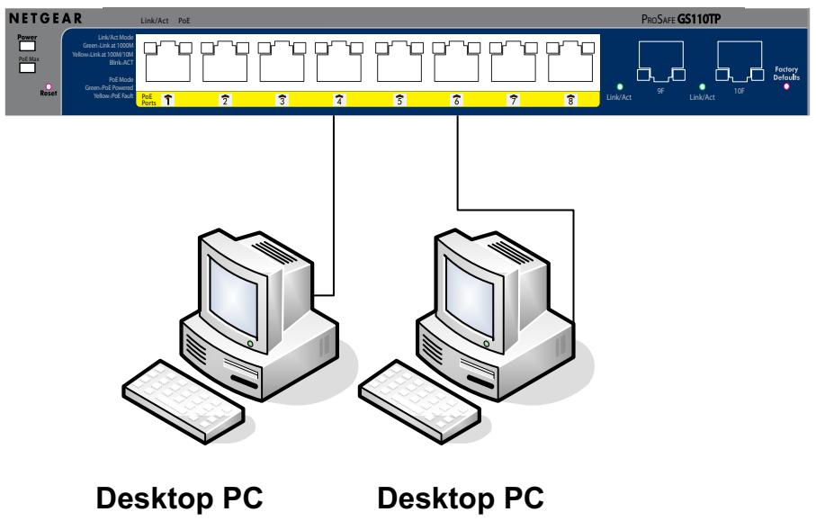
Figure 4-1
Connect each PC to an RJ-45 network port on the Switch front panel (Figure 4-1). Use Category 5 (Cat5) Unshielded Twisted-Pair (UTP) cable terminated with an RJ-45 connector to make these connections.

Note: Ethernet specifications limit the cable length between the switch and the attached device to 100m (328 ft.).
Step 5: Applying AC Power
Before connecting the power cord, select an AC outlet that is not controlled by a wall switch, which can turn off power to the switch. After selecting an appropriate outlet, use the following procedure to apply AC power:
- Connect the end of the supplied IEC AC power adapter cable to the power receptacle on the back of the switch.
- Connect the AC power adapter cable into a power source such as a wall socket or power strip.
When applying power, the Power LED on the switch's front panel illuminates.
If the Power LED does not go on, check that the power cable is plugged in correctly and that the power source is good. If this does not resolve the problem, refer to Appendix A.
Step 6: Managing the Switch using a Web Browser or the PC Utility
The GS110TP Smart PoE Switch contains software for viewing, changing, and monitoring the way it works. This management software is not required for the switch to work. The ports can be used without using the management software. However, the management software enables the setup of VLAN and Trunking features and also improves the efficiency of the switch, which results in the improvement of its overall performance as well as the performance of the network.
After powering up the switch for the first time, the Smart Switch can be configured using a Web browser or a program called Smart Control Center Utility. For more information about managing the switch, see the Gigabit Advanced Smart Switch Series Software Administration Manual on the Smart Switch Resource CD.

Note: When the device powers up, there is a default IP address already configured on the device. The default IP address is 192.168.0.239 and subnet mask 255.255.255.0.
Appendix A Troubleshooting
This chapter provides information about troubleshooting the NETGEAR Smart Switch. Topics include the following:
Troubleshooting Chart
Additional Troubleshooting
Troubleshooting Chart
The following table lists symptoms, causes, and solutions of possible problems.
Table A-1. Troubleshooting Chart
| Symptom | Cause | Solution |
| Power LED is off. | No power is received. | Check the power cord connections, the ON/OFF switch, and the connected device. Ensure all cables used are correct and comply with Ethernet specifications. |
| Link LED is off or intermittent. | Port connection is not working. | Check the crimp on the connectors and make sure that the plug is properly inserted and locked into the port at both the switch and the connecting device. Ensure all cables used are correct and comply with Ethernet specifications. Check for a defective PC adapter card, cable, or port by testing them in an alternate environment where all products are functioning. |
| File transfer is slow or performance degradation is a problem. | Half-duplex or full-duplex setting on the switch and the connected device are not the same. | Make sure the attached device is set to auto-negotiate. |
Table A-1. Troubleshooting Chart
| Symptom | Cause | Solution |
| A segment or device is not recognized as part of the network. | One or more devices are not properly connected, or cabling does not meet Ethernet guidelines. | Verify that the cabling is correct. Ensure all connectors are securely positioned in the required ports. Equipment may have been accidentally disconnected. |
| ACT LED is flashing continuously on all connected ports and the network is disabled. | A network loop (redundant path) has been created. | Break the loop by ensuring that there is only one path from any networked device to any other networked device. |
Additional Troubleshooting
If the suggestions in Troubleshooting Chart do not resolve the problem, refer to the troubleshooting suggestions in this section.
Network Adapter Cards
Ensure the network adapter cards installed in the PCs are in working condition and the software driver has been installed.
Configuration
If problems occur after altering the network configuration, restore the original connections and determine the problem by implementing the new changes, one step at a time. Ensure that cable distances, repeater limits, and other physical aspects of the installation do not exceed the Ethernet limitations.
Switch Integrity
If required, verify the integrity of the switch by resetting the switch. To reset the switch, remove the AC power from the switch and then reapply AC power. If the problem continues, contact NETGEAR technical support. In North America, call 1-888-NETGEAR. If you are outside of North America, please refer to the support information card included with your product.
Auto-Negotiation
The RJ-45 ports negotiate the correct duplex mode and speed if the device at the other end of the link supports auto negotiation. If the device does not support auto negotiation, the switch only determines the speed correctly and the duplex mode defaults to half-duplex.
The gigabit port on the Gigabit module negotiates speed, duplex mode, and flow control, provided that the attached device supports auto-negotiation.
Appendix B
Technical Specifications
Network Protocol and Standards Compatibility
IEEE 802.3i 10BASE-T
IEEE 802.3u 100BASE-TX
IEEE 802.3ab 1000BASE-T
IEEE 802.3x flow control
IEEE 802.3z 1000BASE-X
IEEE 802.3af DTE Power via MDI
Management
Windows 2000 + XP, Vista; Microsoft Explorer 6.0 or higher
IEEE 802.1Q VLAN
IEEE 802.3ad Link Aggregation
IEEE 802.1D Spanning Tree Protocol
IEEE 802.1w Rapid Spanning Tree Protocol
IEEE 802.1X Port Security
IEEE 802.3AB LLDP
SNMP v1, v2c, and v3
HTTP and HTTPS
Port Mirroring (RX, TX, and Both)
IGMP Snooping v1/v2
IEEE 802.1p Class of Service (CoS)
SNTP (Simple Network Time Protocol) 2 servers. Disabled by default.
Jumbo Frame Support
Interface
Eight RJ-45 connectors for 10BASE-T, 100BASE-TX, and 1000BASE-T (Auto Uplink™ on all ports)
Two SFP slots for SFP modules
LEDS
Per RJ-45 port: Speed/Link/Activity
Per SFP port: SFP indicator
Forwarding modes: Store-and-forward
Bandwidth: 20 Gbps
Address database size: 4K media access control (MAC) addresses per system
Mean Time Between Failure (MTBF): 157,004 hours
Power Supply
48V/1.25A 60W external power adapter
Physical Specifications
Dimensions (H x W x D): 236 x 101.6 x 27 mm (9.3 x 4 x 1.07 in)
Weight: 0.7/1.55 (kg/lbs)
Environmental Specifications
Operating temperature: 0^ to 50^ (32 to 122^ )
Operating humidity: 10% to 90% maximum relative humidity, noncondensing
Storage temperature: -20^ to 70^ (-4 to 158^)
Storage humidity: 5% to 95% maximum relative humidity, noncondensing
Electromagnetic Emissions
FCC Class B
CE Class B: Includes EN55022 (CISPR 22), 55024, and 50082-1
VCCI Class B
C-Tick
Safety
UL/cUL (UL 1950)/cUL IEC950/EN60950)
CE (includes EN60950)
IEC950
CB
Numerics
1U 1-3
8-pin 2-3
A
Applying AC Power 4-4
Auto Uplink 2-4
Auto-negotiating 1-2
Autosensing 1-2, 2-3
B
Backpressure 1-2
C
Category 5 Unshielded Twisted-Pair 1-2
Checking the Installation 4-3
Class of Service 1-1
Connecting Devices to the Switch 4-3
Copper 1-1
Crossover 2-4
D
Default IP Address 4-5
Default Reset Button 2-1
Desktop Switching 3-1
Device Hardware Interfaces 2-2
Duplex Mode 2-3
E
Example of Desktop Switching 3-1
F
Factory Default Button 2-4
Factory Defaults 2-1
Flat Surface 4-2
Full-duplex 1-2
G
Gigabit Ports 1-1
H
High-speed Servers 1-1
1
IEEE 802.3i 1-2
IEEE 802.3x 1-2
IEEE Standards 1-2
IEEE-compliant 1-2
Installation Guide 1-4
Installing the Switch 4-2
L
LED Designations 2-2
Low Latency 1-2
M
MAC 1-2
Media Access Control 1-2
N
Netgear Smart Control Center Utility 1-1
0
Operating Conditions 4-2
Operating Environment 4-1
Operating humidity 4-2
Overview 1-1
P
Package Contents 1-4
Pause Frame Flow Control 1-2
Port LEDs 2-2
Power cord 1-4
Preparing the Site 4-1
R
Rack-mount Kit 1-4
Reset Button 2-1
RJ-45 1-2
RJ-45 Ports 2-2
Rubber footpads 1-4, 4-2
s
Site Requirements 4-1
Smart Switch Resource CD 1-4
Straight-through 2-4
System LEDs 2-3
T
Temperature 4-2
Traffic Control 1-1
Troubleshooting Chart A-17
U
User Intervention 2-4
User's Manual 1-4
UTP 4-4
V
Ventilation 4-2
VLAN 1-1
W
Web-based Graphical User Interface 1-1



