
MSS433 - Sélecteur audio-vidéo CLARION - Notice d'utilisation et mode d'emploi gratuit
Retrouvez gratuitement la notice de l'appareil MSS433 CLARION au format PDF.

| Type de produit | Sélecteur audio-vidéo multi-zone |
| Marque | CLARION |
| Modèle | MSS433 |
| Dimensions (appareil principal) | 250 x 27 x 133 mm |
| Dimensions (station de contrôle) | 43 x 66 x 15 mm |
| Profondeur de montage (station) | 16 mm |
| Alimentation | 10-13 V CC, fusible 5 A |
| Nombre d'entrées A/V | 4 (RCA) |
| Nombre de sorties A/V | 3 (RCA) |
| Nombre de stations de contrôle | 3 |
| Sortie audio max | 4 V crête-à-crête |
| Réponse en fréquence audio | 30 Hz - 25 kHz |
| Rapport signal/bruit audio | 90 dB |
| Impédance d'entrée audio | 82 kΩ |
| Niveau de sortie vidéo | 1 V crête-à-crête ±20% |
| Réponse en fréquence vidéo | 39 Hz - 5,5 MHz |
| Impédance d'entrée vidéo | 75 Ω |
| Connecteurs | RCA dorés |
| Commutation caméra de recul | Oui (entrée 4) |
| Fonctionnalités principales | Contrôle multi-zone, sélection indépendante, commutation automatique caméra de recul |
| Entretien | Chiffon doux non statique, pas de nettoyants liquides |
| Sécurité | Ne pas ouvrir, installation par professionnel recommandée |
| Réparabilité | Aucune pièce réparable par l'utilisateur |
| Garantie | Limitée (voir carte de garantie) |
FOIRE AUX QUESTIONS - MSS433 CLARION
Questions des utilisateurs sur MSS433 CLARION
0 question sur cet appareil. Repondez a celles que vous connaissez ou posez la votre.
Poser une nouvelle question sur cet appareil
Téléchargez la notice de votre Sélecteur audio-vidéo au format PDF gratuitement ! Retrouvez votre notice MSS433 - CLARION et reprennez votre appareil électronique en main. Sur cette page sont publiés tous les documents nécessaires à l'utilisation de votre appareil MSS433 de la marque CLARION.
MODE D'EMPLOI MSS433 CLARION
clarion®
SOURCE COMMANDER
MSS433
MULTISTATION
A/V SELECTOR
OWNER'S MANUAL
INSTALLATION GUIDE
OWNER'S MANUAL/INSTALLATION GUIDE
WARNING!
THE CLARION MSS433 MULTISTATION A/V SELECTOR IS DESIGNED FOR SWITCHING OF VIDEO SOURCES FOR REAR SEAT VIEWING ONLY.
THIS PRODUCT IS NOT INTENDED FOR VIEWING BY THE DRIVER WHILE THE VEHICLE IS IN MOTION SINCE SUCH USE MAY DISTRACT THE DRIVER OR INTERFERE WITH THE DRIVER'S SAFE OPERATION OF THE VEHICLE AND MAY RESULT IN SERIOUS INJURY OR DEATH. SUCH USE MAY ALSO VIOLATE STATE LAW.
CLARION DISCLAIMS ANY LIABILITY FOR ANY BODILY INJURY, INCLUDING FATALITIES, OR PROPERTY DAMAGE THAT MAY RESULT FROM ANY IMPROPER OR UNINTENDED USES OF THIS PRODUCT.
ABOUT INSTALLATION
Installation of mobile audio and video components requires experience with a variety of mechanical and electrical procedures. Even though this manual provides general installation and operation instructions for your new Clarion MSS433 Multistation A/V Selector, it does not show the exact installation methods for your particular vehicle.
If you do not have the required knowledge and experience to successfully complete the installation, we strongly recommend consulting an authorized Clarion dealer about professional installation options.
TABLE OF CONTENTS
Introduction. 2
Installation And Operation Precautions. 3
Installation And Wiring 5
Description Of MSS433 Front Connectors 10
Description Of MSS433 Rear Connectors 12
Description Of Control Station 13
Applications Input Configurations 15
Applications Output Configurations 16
Operating the MSS433 17
Troubleshooting 19
Specifications 20
INTRODUCTION
The Clarion MSS433 is a full-featured Multistation A/V Selector specifically created for the mobile environment. When used with the enclosed Control Stations, the system allows true multi-zone control with independent audio/video selection of up to four sources and connection of up to three monitors, each capable of displaying a different audio/video program. Each station provides individual entertainment.
The MSS433 also includes the following features:
- Works with all Clarion monitors
- Accepts up to three individual Control Stations
- All solid-state electronic circuits
Audio level gain controls - Buffered input and output audio/video circuits
Gold-plated RCA connectors - High-quality video.audio selector circuits
Rear Vision Camera automatic switching
About The Manual And Warranty
To start enjoying your new Clarion MSS433 Multistation A/V Selector, please read all remaining instructions listed in this manual. Keep all instructions for future reference.
This product is covered by a limited warranty (see the enclosed warranty card). Save the sales receipt to protect your purchase and aid in warranty service.
INSTALLATION AND OPERATION PRECAUTIONS
Installation Precautions
- This unit operates on an automotive 12-volt negative ground power source and requires additional mobile audio and video components for proper operation.
- Before installation, disconnect the (-) negative lead from the vehicle's battery.
- Use only supplied screws and hardware. Make sure all connections and components are fastened securely.
- At the proposed installation sites, make sure there is adequate space to accommodate both MSS433 and the Control Station dimensions.
-
Use extreme caution when drilling around electrical wiring, brake lines, and fuel lines. Check clearances on both sides of a planned installation surface before drilling any holes or installing any screws.
Always wear protective eyewear when using tools. -
Use only high-quality RCA cables that are no longer than necessary for direct connections to other components in the system. Extra-length audio and video cables can cause signal loss and act as an "antenna" for noise.
- When routing RCA cables, keep them away from power cables and output speaker wires.
Operation Precautions
- Do not allow liquids or foreign objects to enter the MSS433 Multistation A/V Selector or Control Station(s).
- If any unit should become wet, turn off all power and let your authorized Clarion dealer clean or service the equipment.
DO NOT ATTEMPT TO OPEN OR SERVICE THE MSS433 OR CONTROL STATIONS. THE INTERNAL PARTS ARE NOT USER-SERVICEABLE. DOING SO WILL VOID THE WARRANTY.
- Do not place heavy objects on the MSS433 Multistation A/V Selector or Control Station(s).
clarion SOURCE COMMANDER MSS433
- Do not drop or excessively jar the MSS433 Multistation A/V Selector or Control Station(s).
- Do not use liquid cleaners on any surfaces. Only use a soft (cotton or other non-static) cloth to wipe off fingerprints or other imprints from the faceplate or remote control.
- Do not subject the unit to direct sunlight or an extremely hot environment (e.g., closed windows on a hot summer day, direct path of heater vent, etc.).
-
Avoid using the products under the following conditions: - After extended parking on an extremely hot or cold day - Near strong magnetic fields
-
In an environment with excessive humidity, dust, or vibration (e.g., off-road travel, etc.)
INSTALLATION AND WIRING
Parts List
(1) Source Commander MSS433 A/V Selector
(3) Control Stations
(3) Control Station Cables
(2) Mounting L-Brackets
(4) M4 x 8 Pan Head Machine Screws
(4) M4 x 15 Self-tapping Sheet Metal Screws
(1) 4-pin Molex Power Connector
(3) 2-pin Monitor Power Connectors
- Owner's Manual/Installation Guide
Warranty Registration Card
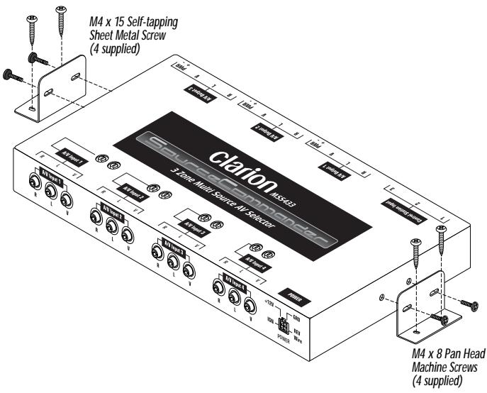
Installing the MSS433
Figure 1. Installing the MSS433.
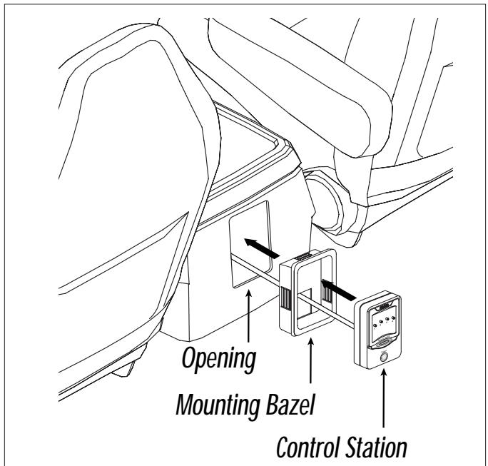
Installing the Control Station
Figure 2. Installing the Control Station in a center console.
MSS433 Wiring for the 4-Pin Power Harness
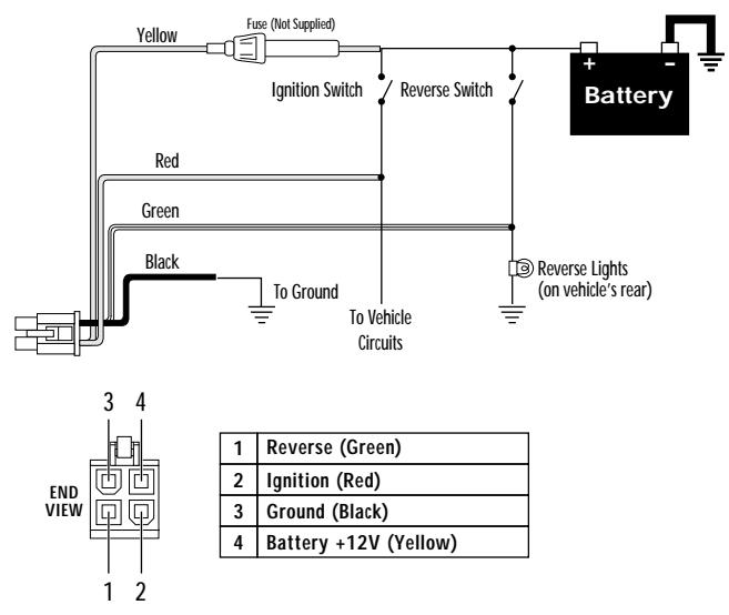
Figure 3. Wiring and pinouts for the 4-pin power harness.
INSTALLATION AND WIRING (CONTINUED)
MSS433 Wiring for DVD Disc Player
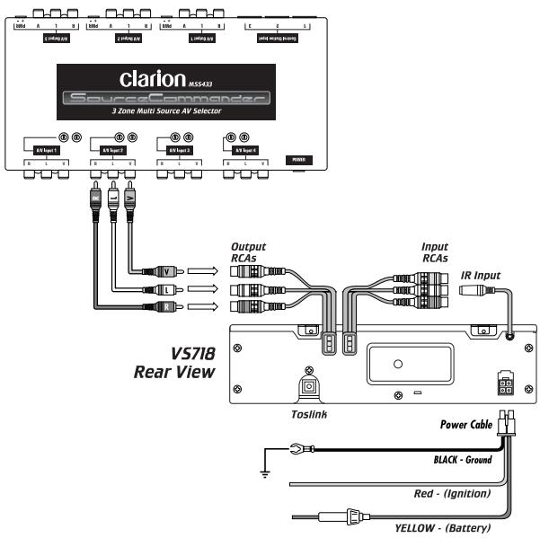
Figure 4. Wiring diagram using a VS718 DVD player.
MSS433 Wiring for VCR
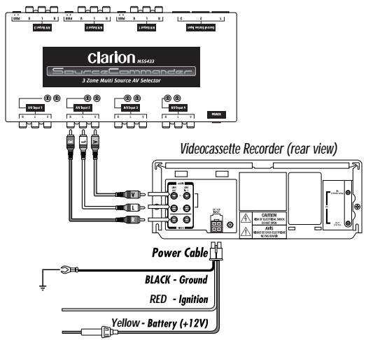
Figure 5. Wiring diagram for a VCR Input.
MSS433 Wiring for Rear Vision Camera
Figure 6. Wiring diagram for a Clarion Rear Vision Camera.
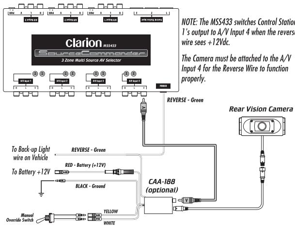
NOTE: The MSS433 does not provide necessary power and signals for the Rear Vision camera. The CAA-188 Camera Power Supply is required.
Power Connector Pinouts
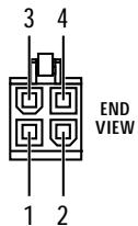
POWER 4-Pin Connector (Male Pins)
| 1 | Reverse (Green) |
| 2 | Ignition (Red) |
| 3 | Ground (Black) |
| 4 | Battery (Yellow) |
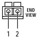
Figure 7. 4- and 2-pin Molex Power connector pinouts.
MONITOR OUTPUT 2-Pin Connector (Male Pins)
| 1 | Negative Lead |
| 2 | Positive Lead |
MSS433 Video and Power Connector Pinouts

A/V INPUT 1~4
RCAs


L
V
Center Conductor is signal (+), Outside conductor is signal ground (-).
R

A/V OUTPUT 1~3
RCAs


L
V
Center Conductor is signal (+), Outside conductor is signal ground (-).
R
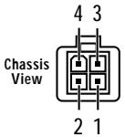
POWER INPUT 4-Pin Molex
| 1 | Reverse (Green) |
| 2 | Ignition (Red) |
| 3 | Ground (Black) |
| 4 | Battery (Yellow) |
MONITOR OUTPUT 2-Pin Connector
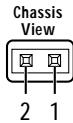
Figure 8. MSS433 Chassis A/V Inputs, Outputs, & Power connectors.
| 1 | Negative Lead |
| 2 | Positive Lead |
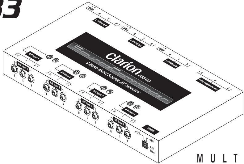
DESCRIPTION OF MSS433 FRONT CONNECTORS
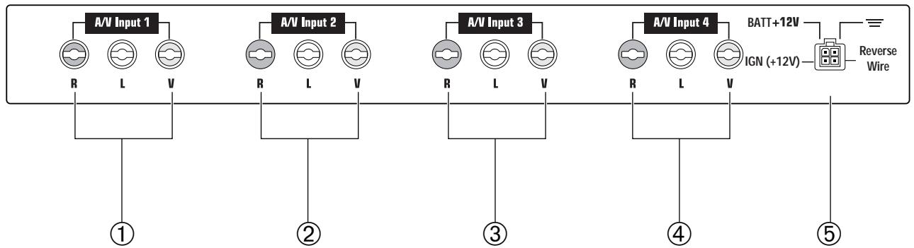
Figure 9. The MSS433's chassis input connectors.
A/V Input Connections (Front Panel)
① A/V INPUT 1 (3-RCA Jacks)
Use a triple RCA A/V cable (not supplied) to connect video and stereo audio from the primary video source (e.g., Clarion CVP9700 VCR, VS718 DVD Player, etc.) to the MSS433 A/V Selector. See Applications on page 15.
Adjust the input gain controls so that the source's level matches the audio level of the other video inputs.
NOTE: Do not connect high level speaker-level wires to these inputs. The MSS433 requires low-level signal inputs only.
② A/V INPUT 2 (3-RCA Jacks)
Same as A/V Input 1. Use these jacks to connect a second video source (e.g., video game console, etc.)
③ A/V INPUT 3 (3-RCA Jacks)
Same as A/V Input 1. Use these jacks to connect a third video source.
④ A/V INPUT 4 (3-RCA Jacks)
Same as A/V Input 1. Use these jacks to connect a fourth video source.
NOTE: When using a optional Clarion Rear Vision Camera, the video connection must be connected to A/V Input 4 to function properly with the reverse wire. See Figure 6 on page 8 for connection configuration.
When +12Vdc is applied to the reverse wire (Pin 4), the MSS433 will automatically override Control Station 1's video selection and switch directly to A/V Input 4. The LED indicator will blink to show that the reverse function is active. The video signal will automatically override any other selection that is being viewed on Monitor 1. When voltage is removed from the reverse wire, the monitor will automatically switch back to the original source selected.
⑤ POWER INPUT CONNECTOR (4-Pin Molex)
Connect the enclosed Molex pigtail to the vehicle's power, ground, and back-up light circuits, (see Figure 3 on page 6).
DESCRIPTION OF MSS43. REAR CONNECTORS (CONT'D)
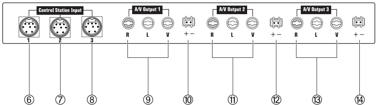
Figure 10. The MSS433's A/V Outputs and Power connectors.
CONTROL STATION 1 (6-Pin Connector)
The Control Station connected to this port provides control and selection of Zone 1 audio/video sources.
⑦ CONTROL STATION 2 (6-Pin Connector)
The Control Station connected to this port provides control and selection of Zone 2 audio/video sources.
CONTROL STATION 3 (6 -Pin Connector)
The Control Station connected to this port provides control and selection of Zone 3 audio/video sources.
⑨ A/V OUTPUT 1 (3-RCA Jacks)
Use this output when connecting the MSS433 to an external (PAL/NTSC-compatible type) video monitor for Zone 1.
⑩ MONITOR 1 OUTPUT (2-Pin Connector)
Connect to the monitor's +12V and ground for Zone 1.
A/V OUTPUT 2 (3 -RCA Jacks)
Use this output when connecting the MSS433 to an external video monitor for Zone 2.
⑫ MONITOR 2 OUTPUT (2-Pin Connector)
Connect to the monitor's +12V and ground for Zone 2.
③ A/V OUTPUT 3 (3-RCA Jacks)
Use this output when connecting the MSS433 to an external video monitor for Zone 3.
⑭ MONITOR 3 OUTPUT (2-Pin Connector)
Connect to the monitor's +12V and ground for Zone 3.
DESCRIPTION OF CONTROL STATION
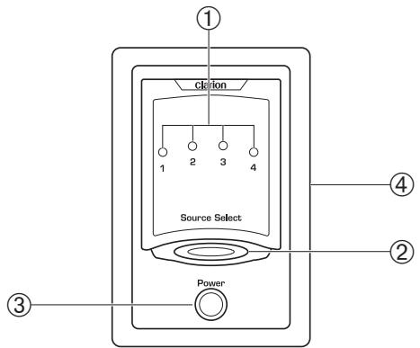
Figure 11. The Control Station's Power button, source LED indicators, and Source Select buttons.
① SOURCE SELECT LEDs
When illuminated, each LED indicates which A/V source is selected. Press the SOURCE SELECT button to change source selection and the corresponding LED will illuminate.
clarion SOURCE COMMANDER MSS433
② SOURCE SELECT Button
Press the SOURCE SELECT button one or more times to step through the different Audio/Video inputs. Each LED illuminates to confirm the source selected.
③ POWER Button
When ignition is applied to the MSS433's ignition lead, all control stations are automatically set into the Stand-By mode (no power output from the monitor's power connector). Press the POWER button on any Control Station and the source LED will illuminate and the monitor will power on.
NOTE: Control Stations
a). If the Ignition is shuts down while the Control Stations are in use, the Control Stations will not automatically turn on when the ignition is activated again. Press the Power button on the Control Station again. The Control Station will power up and reset to number 1 source.
Press and hold the Power button for 2 to 3 seconds to power down the monitor at each of the Control Stations.
④ Mounting Bezel
Outer mounting bezel around each Control Station allows for easy installation. (see page 6 for installation information).
APPLICATIONS INPUT CONFIGURATIONS
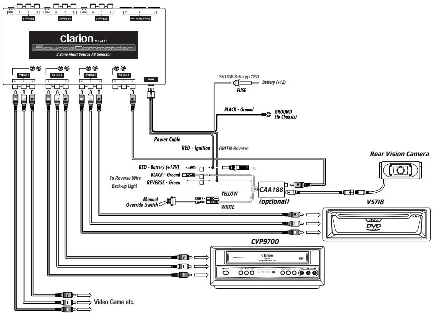
Figure 12. Using the MSS433 Input Connectors.
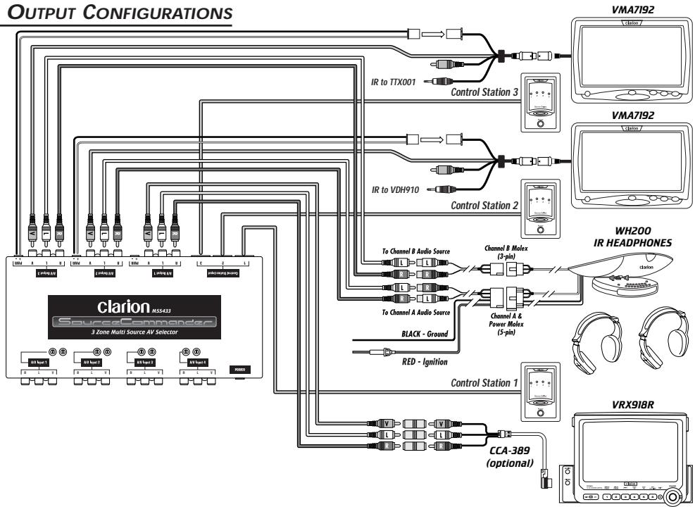
APPLICATIONS OUTPUT CONFIGURATIONS
Figure 13. Using the MSS433 Output Connectors.
OPERATING THE MSS433 SYSTEM
Reverse Mode (Control Station 1 ONLY)
When using this control station with an optional Rear Vision Camera and CAA188 power supply, the camera's source will automatically switch when the car is put into the reverse gear.
The LED indicator will flash designating the Reverse Mode and the monitor will display the video signal from the Rear Vision Camera.
NOTE: Rear Vision Camera Connections
a). The Rear Vision Camera's video output from the CAA188 must be connected directly to A/V Input 4 only. (see MSS433 Wiring for Rear Vision Camera on page 8).
When the vehicle is taken out of the reverse gear, the last video source chosen, before the reverse mode, is displayed and the source LED is illuminated constantly.
Viewing A Videocassette (If Installed)
- After system and individual control station power is on, insert a videocassette in the VCR and press PLAY on the corresponding IR Remote Control. Use the IR remote controls to control the VCR functions through the monitor's IR Sensor.(CCE-002 is required for CVP9700)
- At any Control Station, press the SOURCE SELECT button one or more times until the LED illuminates for the VCR source input. Its TV monitor will now display the source selected.
- Adjust the headphones or audio system's volume control to a desired listening level.
Viewing A Video Game (If Installed)
- After system and individual control station power is on, power on the video game player and insert a desired game cartridge.
- At any Control Station, press the SOURCE SELECT button one or more times until the LED illuminated for the
clarion SOURCE COMMANDER MSS433
video game source input. Its TV monitor should now display the selected source.
- Adjust the audio system's volume control to a desired listening level.
Viewing A DVD (VS718)
- After system and individual control station power is on, insert a DVD in the DVD player and press PLAY on the corresponding IR Remote Control. Use the IR remote controls to control the DVD functions through the monitor's IR Sensor.
- At any Control Station, press the SOURCE SELECT button one or more times until the LED illuminates for the DVD source input. Its TV monitor will now display the source selected.
- Adjust the headphones or audio system's volume control to a desired listening level.
TROUBLESHOOTING
| Symptom | Cause | Solution |
| System does not work. | Fuse is blown. | Replace external fuse with the same value. |
| Power wires not connected. | Check IGNITION and GROUND wiring at MSS433; check battery connections. | |
| No Remote-On | Check for +12 V on Battery lead. If voltage is low, use relay circuit. | |
| No LED illumination on the Control Station. | No Ignition power | Check for +12 V on Ignition lead to MSS433. If voltage is low, use relay circuit. |
| Station DIN not inserted fully into 6-pin connector. | Properly connect to MSS433; insert connector and lock into place. | |
| No sound from IR Headphones. | Station power is off. | Press the POWER button once to turn on control unit on. |
| Stand-by power up mode. | Press the Power button once to activate the Control Station. Check for source LED illumination. | |
| Volume down on IR headphones. | Check volume level on IR head- phone set. | |
| No sound from in-dash monitor | CCA389 not connected properly. | Connect CCA389 to optional video input. |
| Symptom | Cause | Solution |
| No sound from in-dash monitor | Video source not selected on in-dash unit. | Switch the input control on the in-dash unit to select the video source. |
| No video from external RCA outputs. | Power is off at Station. | At Control Station, press the POWER button once to turn on the Control Station. |
| No video from in-dash monitor. | CCA389 not connected properly. | Connect CCA389 to optional video input. |
| No Rear Vision | Reverse wire not connected. | Connect Reverse wire on MSS433 to +12V source when vehicle shifted into reverse. |
| Camera not connected properly. | Connect a Clarion Rear Vision Camera to the A/V INPUT 4 video connector. | |
| No Power to CAA188 | Check power and ground connections to CAA188. | |
| Reverse Wire not con- nected on CAA188 camera power supply. | Check for proper connection and +12 V on Reverse Wire when vehicle is in reverse gear. |
clarion SOURCE COMMANDER MSS433
MSS433 SPECIFICATIONS
Audio Specifications -
Maximum Output: 4V_p - p (peak to peak)
Frequency Response: 30Hz to 25kHz
S/N Ratio (A-wtd): 90 dB
Input Sensitivity: 1.0V_p - p (peak to peak)
Input Impedance: 82k Ohms
Input/Output Gain: 0dB +/-2dB at Max volume with 600 Ohm load.
Video Specifications -
Output Level: 1.0V_p - p + / - 20% (peak to peak)
Frequency Response: 39Hz to 5.5MHz
Video Input/Output Gain: 0dB +/-2dB with 75 Ohm load
Input Sensitivity: 0V_p - p + / - 20% (peak to peak)
Input Impedance: 75 Ohms
General Specifications -
Power Requirement: 10V_dc - 13V_dc
Fuse Rating: 5 A
Dimensions (w x h x d): 9.84 × 1.06 × 5.24 in.
(250× 27× 133mm)
CONTROL SPECIFICATIONS
Dimensions (w x h x d): 1.7 × 2.6 × .60 in.
(43 × 66 × 15 ~mm)
Mounting Depth: .63 in. (16 mm); behind panel
Mounting Hole Diam.: 1.9 × 2.8 in. (48 x 72 mm)
Due to Clarion's ongoing research and development, the product specifications and appearances listed in this manual are subject to change without prior notice.
Clarion Co., Ltd.
- clarion®
- SOURCE COMMANDER
- MSS433
- A/V SELECTOR
- OWNER'S MANUAL/INSTALLATION GUIDE
- WARNING!
- ABOUT INSTALLATION
- TABLE OF CONTENTS
- INTRODUCTION
- About The Manual And Warranty
- INSTALLATION AND OPERATION PRECAUTIONS
- Installation Precautions
- Operation Precautions
- clarion SOURCE COMMANDER MSS433
- INSTALLATION AND WIRING
- Parts List
- INSTALLATION AND WIRING (CONTINUED)
- MSS433 Wiring for Rear Vision Camera
- Power Connector Pinouts
- MSS433 Video and Power Connector Pinouts
- DESCRIPTION OF MSS433 FRONT CONNECTORS
- A/V Input Connections (Front Panel)
- DESCRIPTION OF MSS43. REAR CONNECTORS (CONT'D)
- DESCRIPTION OF CONTROL STATION
- ② SOURCE SELECT Button
- ③ POWER Button
- NOTE: Control Stations
- ④ Mounting Bezel
- APPLICATIONS INPUT CONFIGURATIONS
- OPERATING THE MSS433 SYSTEM
- Reverse Mode (Control Station 1 ONLY)
- Viewing A Videocassette (If Installed)
- Viewing A Video Game (If Installed)
- Viewing A DVD (VS718)
- TROUBLESHOOTING
- MSS433 SPECIFICATIONS
- Audio Specifications -
- Video Specifications -
- General Specifications -
- CONTROL SPECIFICATIONS
Marque : CLARION
Modèle : MSS433
Catégorie : Sélecteur audio-vidéo