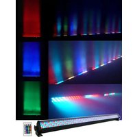
Rockstrip 252 - Éclairage Rockville - Notice d'utilisation et mode d'emploi gratuit
Retrouvez gratuitement la notice de l'appareil Rockstrip 252 Rockville au format PDF.


| Type de produit | Bande lumineuse LED RGB |
| Marque | Rockville |
| Modèle | Rockstrip 252 |
| Nombre de LED | 252 LED RGB |
| Longueur | 2,5 mètres |
| Largeur | 10 mm |
| Poids | Environ 200 g |
| Alimentation | Adaptateur secteur 12V DC (inclus) |
| Puissance | 36 W |
| Fonctions principales | Éclairage RGB, 44 modes de couleur, synchronisation musicale, télécommande infrarouge |
| Télécommande | Infrarouge, incluse (pile bouton CR2025 incluse) |
| Angle de faisceau | 120 degrés |
| Durée de vie | Jusqu'à 50 000 heures |
| Indice de protection | IP20 (usage intérieur uniquement) |
| Matériau | PCB flexible avec revêtement silicone |
| Température de couleur | RGB (16,8 millions de couleurs) |
| Entretien et nettoyage | Nettoyer avec un chiffon doux et sec ; ne pas utiliser de produits chimiques |
| Sécurité | Ne pas immerger dans l'eau ; débrancher avant nettoyage ; utiliser uniquement l'adaptateur fourni |
| Pièces détachées et réparabilité | Adaptateur et télécommande disponibles séparément ; réparation par un professionnel recommandée |
| Garantie | 1 an |
FOIRE AUX QUESTIONS - Rockstrip 252 Rockville
Questions des utilisateurs sur Rockstrip 252 Rockville
0 question sur cet appareil. Repondez a celles que vous connaissez ou posez la votre.
Poser une nouvelle question sur cet appareil
Téléchargez la notice de votre Éclairage au format PDF gratuitement ! Retrouvez votre notice Rockstrip 252 - Rockville et reprennez votre appareil électronique en main. Sur cette page sont publiés tous les documents nécessaires à l'utilisation de votre appareil Rockstrip 252 de la marque Rockville.
MODE D'EMPLOI Rockstrip 252 Rockville
ROCKVILLE
ROCKSTRIP 252
LED 5 CHANNEL DMX RGB COLOR STRIP DJ WASH UP LIGHT BAR
OWNER'S MANUAL
ATTENTION: WATCH THIS VIDEO BEFORE FIRST USE!
Who reads manuals?
Scan the QR code or go to rockvillesupport.com/rockstrip-252 to access how-to video(s), assembly video(s), the owner's manual, and other important information you may need to get the most out of your item.
If you prefer written instructions, please read ahead!
With Rockville you get many options.

Missing items? If you ordered a bundle that includes more than one product and you are missing part of your bundle then it just means your order shipped from two different warehouses. You will receive the remaining items very soon. If you have any concerns or inquiries, feel free to call our customer support center at 1-646-758-0144, 24 hours a day/7 days a week.
Thank you for purchasing the Rockville ROCKSTRIP 252. Please read the owner's manual carefully for proper use of your ROCKSTRIP 252. Should you need assistance, please call our technical help line at 1-646-758-0144, 24 hours a day/7 days a week.
Includes
- ROCKSTRIP 252
• 2x tall mounting brackets
• 2x short mounting brackets - Power cord
- owner's manual
- warranty
IMPORTANT SAFETY INSTRUCTIONS

NO USER SERVICEABLE PARTS INSIDE. WE RECOMMEND TAKING THE UNIT TO A QUALIFIED SERVICE TECHNICIAN FOR ANY REPAIRS.
• To reduce risk of electric shock, never open the unit. There are no user serviceable parts, refer service to an authorized Rockville service center.
- Avoid looking directly into the lights.
- Do not expose this unit to any kind of moisture.
• The products housing may become hot during operation. Do not touch.
- Please ensure that the unit is situated in a properly ventilated area. Allow at least 20 inches between this device and a wall.
- Do not attempt to operate this unit if the power cord has been frayed or broken.
- Do not attempt to break off or remove the ground prong. This prong is used to reduce the risk of electrical shock and fire in case of an internal short.
- Never plug this unit into a dimmer pack.
- Do not operate this unit if it is damaged.
- This unit is intended for indoor use only.
- During long periods of non-use, disconnect the unit from power source.
• Always mount this unit in a safe and stable matter.
- Power supply cords should be routed so that they are not likely to be walked on or pinched by items placed upon or against them, paying particular attention to the point of exit from the unit.
- To avoid unnecessary wear and to improve the unit's lifespan, unplug the unit when not in use for extended periods of time.
- When choosing a location for your device, make sure to avoid impact, vibration, dust, hot and cold temperatures and dampness. Furthermore, no powerful transformers or motors must be used close to the device.
• The effect light must only be operated at a maximum ambient temperature of 104° Fahrenheit (40 °C).
- Never cover the device. Make sure when mounting with other equipment that there is sufficient ventilation. Maintain a sufficient distance to other devices and walls. Never install the effect light in direct proximity of heat sources. Do not point any strong spot lights or light sources towards the device. This may cause overheating (danger of fire!).
- Do not drill or screw additional screws into the casing in order to fasten the device.
• The device must be mounted out of normal reach.
- Illuminated objects must be at least 0.5m away from the device's light emission source. Easily flammable materials such as decorative fabrics must also have a distance of at least 0.5m to the device. Otherwise, such objects may catch fire!
- When mounting the product, make sure that the power cord is neither jammed nor damaged by sharp edges.
- During installation or service work, the area below the place of installation must be cordoned off.
- The installation surface or mounting fixture needs to be designed in a way that it can take 10 times its load capacity for at least 1 hour without permanent damaging deformation.
- It is also essential that the device is secured by means of a second safety restraint that is independent of the actual mounting supports when installing it in an elevated position. No part of the installation must fall down if the main suspension system fails.
- Observe all relevant regulations of your country when installing the device.
- Please keep the lenses out of direct sunlight as it can cause heat build up which will cause serious damage to the unit.

ATTENTION
If using a 220V/50Hz power supply, do not connect more than 14 units in series. Be sure to use a separate power supply for any additional units.
If using a 110/60Hz power supply, do not connect more than 9 units in series. Be sure to use a sparate power supply for any additional units.
Functions

- Power switch
- Power In socket w/user serviceable fuse
- DMX in
- Controls: Menu - Press repeatedly to see mode options
Up - Scroll up through settings
Down - Scroll down through settings
Enter - Enter submenu
- Digital display
- Infra red remote control sensor
- Microphone
- DMX out
- Power out
Remote
- AUTO: Chase mode, cycle through chases 1 - 8.
- SOUND: Press to activate sound mode. Use +/- to select sound mode A or B.
-
DMX: Select DMX address. Press for 2 seconds to set the address to 001. Use +/- to cycle through DMX addresses/channels.
-
BLACK OUT: Turns all lights off.
-
RED, GREEN, BLUE: Turns on corresponding light.
-
WHITE: Turns on all lights.
-
+/- : Increase or decrease chase speed, DMX address, sound mode, and strobe speed.
-
Number pad: Use to directly select chase mode or sound mode.
-
JUMP: Press repeatedly to select chases 1 - 8.
-
FADE: Activate/deactivate color fade mode.
-
COLOR: Press to cycle through 7 preset colors.
-
FLASH: Activate/deactivate strobe function. Use +/- to adjust strobe speed.
Please note:
- Strobe function is only available when the color is set to red, green, blue, or white.
- In DMX mode, you can quickly change the DMX address by long pressing the +/-

Installation
For floor or wall installation, use the appropriate type of screws and anchors, if necessary, to secure the fixture to the mounting surface.

The Rockstrip 252 can be truss mounted by using two lighting clamps. We recommend Rockville LC70 Light Clamps (shown).
- Secure the mounting clamp to the fixture as shown below. Don't screw the bolt all the way in.
- Slide the clamp assembly onto the truss (a). Use the locking screw (b) and the bolt (c) to secure the clamp. Do not overtighten.
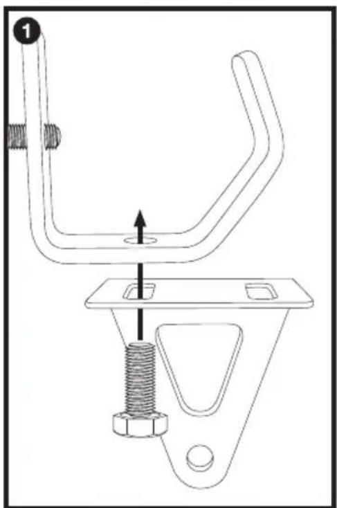

Please note: Like with 99% of all lights on the market, to mount this light to a truss you need to buy a clamp. Clamps come in different shapes and sizes depending on your application. For most applications the best clamp for you will likely be the Rockville LC70. However, this unit will work with other clamps made by Chauvet and other brands.
Operation
Use the MENU button to enter the settings menu. Use the UP and DOWN buttons to select the desired setting and set their values. Press ENTER button to save your selection. Press MENU to exit.
Display
![graph TD A["Addr"] --> B["AO0 1"] --> C["AS 12"] D["CHnd"] --> E["3CH"] --> F["4CH"] G["7CH"] --> H["24CH"] I["28CH"] --> J["SL04"] K["SLAU"] --> L["SLO1"] --> M["Slave mode"] N["AU+O"] --> O["Pr-0"] --> P["Chase 1 - 8 cycle running"] Q["Pr-1"] --> R["Pr-8"] S["Pr-9"] --> T["SP01"] --> U["Chase 1 -…](/content/2026/07/1456932/images/cb815bad6edb9dffaf447b832ec9ddf304e92dcc7f681482d440e6d840b59da6.jpg)
Operating Modes
DMX Mode
The ROCKSTRIP 252 can be controlled via any DMX controller. Simply link the fixture to your DMX controller, program a chase, and then run the chase. You can also daisy chain multiple units. When you run a chase, the units will automatically be set to the appropriate DMX channel.
If you are using multiple fixtures and you want independent control of each fixture, set them 4 DMX channels apart like the example below:
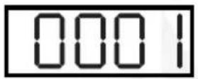


Master/Slave Mode
In this mode you can link up to 16 fixtures together via the DMX IN/DMX OUT ports. The first fixture will control all the other fixtures which will automatically switch to slave mode. Any fixture can act as a master fixture.
DMX Controller Function
When using a DMX controller, use the chart below to reference each channel's function.
3 Channel Mode
| Ch. | Function | Value | Description |
| 1 | Red Dimmer | 0 – 255 | Adjust individual LED brightness |
| 2 | Green Dimmer | 0 – 255 | |
| 3 | Blue Dimmer | 0 – 255 |
4 Channel Mode
| Ch. | Function | Value | Description |
| 1 | Red Dimmer | 0 – 255 | Adjust individual LED brightness |
| 2 | Green Dimmer | 0 – 255 | |
| 3 | Blue Dimmer | 0 – 255 | |
| 4 | Master Dimmer | 0 – 255 |
7 Channel Mode
| Ch. | Function | Value | Description | |
| 1 | Red Dimmer | 0 – 255 | Adjust individual LED brightness | |
| 2 | Green Dimmer | 0 – 255 | ||
| 3 | Blue Dimmer | 0 – 255 | ||
| 4 | Master Dimmer | 0 – 255 | ||
| 5 | CH7=0 | Strobe Speed (in dimmer mode) | 0 – 255 | 0: Strobe off |
| CH7>0 | Running Speed | 0 – 255 | In chase mode (slow to fast) | |
| 6 | Chase Mode | 0 – 25 | Mode 0 (cycles through chases 1 – 8) | |
| Chase Mode | 26 – 255 | Mode 1 – 9 | ||
| 7 | Dimmer Mode | 0 | Custom control | |
| Chase Mode | 1 – 13 | |||
| Sound Mode | 14 – 27 | A0 (runs the entire all mode A cycle) | ||
| 28 – 139 | A1 – A8 | |||
| 140 – 153 | B0 (runs the entire all mode B cycle) | |||
| 154 – 255 | B1 – B8 | |||
24 Channel Mode
| Ch. | Function | Value | Description |
| 1 | 1st Light Dimmer | 0 – 255 | Adjust LED brightness |
| 2 | 2nd Light Dimmer | 0 – 255 | |
| 3 | 3rd Light Dimmer | 0 – 255 | |
| ......... | ......... | 0 – 255 | ......... |
| 22 | 22nd Light Dimmer | 0 – 255 | Adjust LED brightness |
| 23 | 23rd Light Dimmer | 0 – 255 | |
| 24 | 24th Light Dimmer | 0 – 25 |
28 Channel Mode
| Ch. | Function | Value | Description | |
| 1 | 1st Light Dimmer | 0 - 255 | Adjust LED brightness | |
| 2 | 2nd Light Dimmer | 0 - 255 | ||
| 3 | 3rd Light Dimmer | 0 - 255 | ||
| ······ | ······ | 0 - 255 | ······ | |
| 22 | 22nd Light Dimmer | 0 - 255 | Adjust LED brightness | |
| 23 | 23rd Light Dimmer | 0 - 255 | ||
| 24 | 24th Light Dimmer | 0 - 25 | ||
| 25 | Master Dimmer | 0 - 255 | ||
| 26 | CH28=0 | Strobe Speed (in dimmer mode) | 0 - 255 | 0: Strobe off |
| CH28>0 | Running Speed | 0 - 255 | In chase mode (slow to fast) | |
| 27 | Chase Mode | 0 - 25 | Mode 0 (cycles through chases 1 - 8) | |
| Chase Mode | 26 - 255 | Mode 1 - 9 | ||
| 28(Function Channel) | Dimmer Mode | 0 | Custom control | |
| Chase Mode | 1 - 13 | |||
| Sound Mode | 14 - 27 | A0 (runs the entire all mode A cycle) | ||
| 28 - 139 | A1 - A8 | |||
| 140 - 153 | B0 (runs the entire all mode B cycle) | |||
| 154 - 255 | B1 - B8 | |||
DMX Termination (Optional)
The last fixture of a DMX chain has to be “terminated”. This prevents electrical noise from disturbing and corrupting the DMX control signals. To terminate the last fixture solder a 1/4 Watt, 120 ohm resistor across the DATA - and DATA + wires. The connections are illustrated below. If you are only connecting a few fixtures which are close together and use a short run to the controller, you may be able to operate without a terminator.
![graph TD A["1: DMX IN, DMX OUT"] --> B["4"] C["2: DMX IN, DMX OUT"] --> B D["3: DMX IN, DMX OUT"] --> B B --> E["5: DMX IN, DMX OUT"] E --> F["6 (last fixture)"] F --> G["Pin 2: 120 Ohm/1W"] F --> H["Pin 3: 120 Ohm/1W"]](/content/2026/07/1456932/images/8c1abb5c527c51480b446f9440bec82093362ec069e6b76f69cb43fbcb0cbc7a.jpg)
Troubleshooting
| PROBLEM | SOLUTION |
| No power | 1. Make sure the unit is plugged in and that the power switch is in the on position.2. Make sure the power cord is not damaged.3. Check and replace the fuse if necessary. |
| No fixture DMX response | 1. Make sure that the starting address at the fixture is correct and all other fixtures are set to the same address.2. Make sure the DMX channel setting is the same for all fixtures.3. Make sure you are using the correct faders on the controller.4. Make sure you are using the correct fixture template and assign controller faders accordingly.5. Change the signal polarity at the controller.6. Check your DMX cables to ensure they are not damaged.7. Check that the DMX cables are connected properly and are wired correctly (pin 3 is “hot”; on some other DMX devices pin 2 may be ‘hot’). Also, check that all cables are connected to the right connectors; it does matter which way the inputs and outputs are connected. |
| Unit does not respond to sound | 1. Quiet or high pitched sounds will not activate the unit.2. Make sure that Sound Activate mode is turned on. |
Fuse Replacement


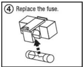

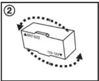
Switching Voltage


Features and Specifications
• 252 bright LED's
- Static colors and RGB color mixing with or without DMX controller
• LED's: 84 red + 84 green + 84 blue
• Built-in automated programs
- Master/slave controls allow you to link multiple lights together to clone the same program
• Additional power output to link multiple lights together easily (up to 20 max)
- High speed color changer 1 – 13Hz (one of the fastest speeds on the market)
• Bulb Life: 100,000 hours life
• Red, greed, and blue LED's (RGB)
- Dimmer: 0 - 100%
• Strobe with adjustable speed
- Lights can operate safely without overheating for months straight!
• Control: Standard DMX-512 controls with 4 or 5 channels
• 3-Pin DMX input and output for linking lights
• Lux: 1,452 @ 1m
• 110/220 volt switchable (90-250V AC 50-60Hz)
- Fuse: 2A/Max Power: 50V
• Weight: 3.97 Lbs
- Dimensions: 40.16'' × 2.64'' × 2.56''
ROCKVILLE

RockvilleAudio.com
- ROCKVILLE
- ROCKSTRIP 252
- ATTENTION: WATCH THIS VIDEO BEFORE FIRST USE
- WHO READS MANUALS
- INCLUDES
- IMPORTANT SAFETY INSTRUCTIONS
- NO USER SERVICEABLE PARTS INSIDE. WE RECOMMEND TAKING THE UNIT TO A QUALIFIED SERVICE TECHNICIAN FOR ANY REPAIRS
- ATTENTION
- REMOTE
- PLEASE NOTE
- INSTALLATION
- OPERATION
- OPERATING MODES
- DMX MODE
- MASTER/SLAVE MODE
- DMX CONTROLLER FUNCTION
- 3 CHANNEL MODE
- 4 CHANNEL MODE
- 7 CHANNEL MODE
- DMX TERMINATION (OPTIONAL)
- FEATURES AND SPECIFICATIONS
- ROCKVILLEAUDIO.COM
Marque : Rockville
Modèle : Rockstrip 252
Catégorie : Éclairage