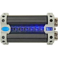
RFC50F V2 - Amplificateur audio Rockville - Notice d'utilisation et mode d'emploi gratuit
Retrouvez gratuitement la notice de l'appareil RFC50F V2 Rockville au format PDF.


| Type de produit | Haut-parleur coaxial 2 voies |
| Marque | Rockville |
| Modèle | RFC50F V2 |
| Dimensions | 5 x 7 pouces (127 x 178 mm) |
| Poids | 1,2 kg |
| Alimentation | Passive, sans alimentation externe |
| Puissance nominale (RMS) | 50 Watts |
| Puissance maximale | 100 Watts |
| Impédance | 4 ohms |
| Réponse en fréquence | 60 Hz - 20 kHz |
| Sensibilité | 92 dB |
| Fonctions principales | Reproduction audio, tweeter intégré |
| Entretien et nettoyage | Nettoyer avec un chiffon doux et sec |
| Sécurité | Éviter l'humidité et les chocs |
| Pièces détachées | Non disponibles individuellement |
| Réparabilité | Faire appel à un centre de service agréé |
| Utilisation recommandée | Enceinte arrière ou avant dans un véhicule |
| Garantie | 1 an |
FOIRE AUX QUESTIONS - RFC50F V2 Rockville
Questions des utilisateurs sur RFC50F V2 Rockville
0 question sur cet appareil. Repondez a celles que vous connaissez ou posez la votre.
Poser une nouvelle question sur cet appareil
Téléchargez la notice de votre Amplificateur audio au format PDF gratuitement ! Retrouvez votre notice RFC50F V2 - Rockville et reprennez votre appareil électronique en main. Sur cette page sont publiés tous les documents nécessaires à l'utilisation de votre appareil RFC50F V2 de la marque Rockville.
MODE D'EMPLOI RFC50F V2 Rockville

ROCKVILLE
CAPACITOR WIRING and CHARGING GUIDE
WIRING THE CAPACITOR (Diagram A)
NOTE: The following wiring instructions are for general purposes. For specific wiring instructions for the RFC50F, RFC30F, RXC50D V2, and RXC20D V2, please refer to the manual provided with your unit.
1) Determine the Installation Location: Place the capacitor as close to the amplifier as possible to minimize performance loss due to cable length. Ensure the capacitor is securely mounted to avoid damage or injury in the vehicle.
2) Connecting the Capacitor: Connect the capacitor in-line between the amplifier's power terminal and the vehicle battery's positive terminal. Attach the amplifier's power cable to the capacitor's positive output terminal. Then, connect the capacitor's positive input terminal to the vehicle's battery positive terminal or an inline fuse (if available).
3) Remote Turn-On (RFC-F series and RXC-D series only): Although the diagrams below do not show it, the RFC-F and RXC-D series capacitors include a remote turn-on terminal. Connect the capacitor's remote turn-on terminal to the vehicle's ACC/Ignition. The RXC-D series' remote turn-on terminal has four ports to which you can connect up to three amps. The fourth terminal is connected to the vehicle's ACC/Ignition.
4) Ground Connection: Connect the capacitor's negative (ground) input terminal to the vehicle chassis. Ensure that there is no paint or other insulation preventing a solid ground connection. The RXC-D series features 3 negative output terminals to facilitate connecting the negative (ground) terminal of up to 3 amps. Connect the capacitor's negative input terminal to any metal part of your vehicle's chassis. Ensure that there is no paint or other insulation preventing a solid ground connection.
NOTE: Rockville capacitors are shipped fully discharged. Follow the instructions below to charge your capacitor.
CHARGING THE CAPACITOR (Diagrams B and C):
1) Removing the In-Line Fuse: Before charging, remove any in-line fuse between the capacitor's positive terminal and the vehicle's battery. Replace it with the provided resistor (46 ohm, 2 watt). The resistor helps prevent overload when the capacitor is connected to power.
IMPORTANT: The resistor is for one-time use during initial charging. If the capacitor needs to be recharged, use the same type of resistor or one with a higher impedance. Do not use a resistor with lower wattage, as it may overheat and crack or explode.
2) Monitoring Voltage with a Voltmeter: To monitor the charge, use a voltmeter. Place the positive probe on the capacitor's positive terminal and the negative probe on the ground terminal. Set the voltmeter to Volts DC. Once the voltage reads 11-12 volts, the capacitor is fully charged.
3) Reinstalling the Power Fuse: Reinsert the power fuse into the fuse holder. You may notice a spark when reinstalling the fuse—this is normal.
Alternatively, you can use a test light to charge the capacitor (Diagram C). The test light consists of a probe (similar to a screwdriver) with a small light bulb and an alligator clip. Attach the alligator clip to one side of the fuse holder and touch the probe to the other side. The test light bulb will illuminate. Continue to hold the test light until the bulb goes out, indicating the capacitor is charged. Once charged, reinsert the power fuse into the fuse holder.
DIAGRAM A

DIAGRAM B

DIAGRAM C

RockvilleAudio.com
©2024 ROCKVILLE // The information presented is subject to change and/or improvement without notice.


Marque : Rockville
Modèle : RFC50F V2
Catégorie : Amplificateur audio