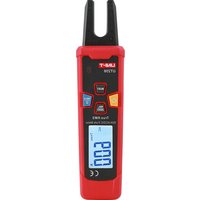
UT256 - Multimètre Uni-T - Notice d'utilisation et mode d'emploi gratuit
Retrouvez gratuitement la notice de l'appareil UT256 Uni-T au format PDF.


| Type de produit | Multimètre numérique |
| Marque | Uni-T |
| Modèle | UT256 |
| Affichage | Écran LCD 3 1/2 digits, 1999 counts |
| Tension continue (DCV) | 600 mV / 6 V / 60 V / 600 V |
| Tension alternative (ACV) | 600 V |
| Résistance (Ohm) | 600 Ω / 6 kΩ / 60 kΩ / 600 kΩ / 6 MΩ / 60 MΩ |
| Test de continuité | Oui, seuil < 50 Ω |
| Test de diode | Oui |
| Capacité | 60 nF / 600 nF / 6 µF / 60 µF / 600 µF / 6 mF |
| Fréquence | 10 Hz – 60 MHz |
| Calibrage automatique | Auto-ranging |
| Fonction Data Hold | Oui |
| Rétroéclairage | Oui |
| Alimentation | 2 piles AAA (1,5 V) |
| Dimensions (L x l x h) | 130 x 63 x 28 mm |
| Poids (avec piles) | Environ 100 g |
| Catégorie de sécurité | CAT II 600 V |
| Entretien et nettoyage | Essuyer avec un chiffon doux et sec. Ne pas utiliser de solvants. |
| Pièces détachées / réparabilité | Piles remplaçables. Fusible de protection interne (F 200 mA / 250 V) |
| Accessoires fournis | Pinces de test, pile, manuel d'utilisation |
FOIRE AUX QUESTIONS - UT256 Uni-T
Questions des utilisateurs sur UT256 Uni-T
0 question sur cet appareil. Repondez a celles que vous connaissez ou posez la votre.
Poser une nouvelle question sur cet appareil
Téléchargez la notice de votre Multimètre au format PDF gratuitement ! Retrouvez votre notice UT256 - Uni-T et reprennez votre appareil électronique en main. Sur cette page sont publiés tous les documents nécessaires à l'utilisation de votre appareil UT256 de la marque Uni-T.
MODE D'EMPLOI UT256 Uni-T
UT256 60A AC/DC Fork Meter
I. Overview
UT256 is a safe and reliable dedicated AC/DC digital fork meter with stable performance (herein after referred to as clamp meter). The design of fork-shaped clamp head enables the current measurement to be more convenient. With audible and visual alarm function, the meter allows users to obtain test results more intuitively. Featuring fashion appearance, durable, portable, UT256 has multiple functions such as backlight, REL, ZERO, HOLD, which makes it an ideal measurement tool for users.
II. Accessories
Open the package box and take out the meter. Check the following items carefully to see any missing or damaged part.
- User Manual.....1 piece
- Lanyard....1 piece
- Battery....1 pair
- Carrying bag.....1 piece
III. Rules for Safe Operation
Please pay attention to the "Warning Signs and Sentences". Warnings mean the situations and behaviors that endanger the user or cause losses to the meter or the equipment to be measured. The meter is designed in accordance with IEC/EN61010-1, 61010-2-032 Safety Standard and EN61326-1 Electromagnetic Compatibility, and complies with the safety standard of double insulation, over-voltage CAT III 600V and pollution level 2, Indoor Use. If you fail to use the meter according to relevant operation instructions, the protection provided by the meter is likely to be weakened or undermined.
- Prior to using, please check the clamp meter so as to prevent any damage or abnormality. If you find the insulating layer of the shell is damaged obviously, the display screen cannot work, etc., or you consider that the clamp meter cannot work well, please don't use the clamp meter any more.
- It is strictly prohibited to use the clamp meter without the rear cover or battery cover, otherwise, shock hazard may occur.
- When carrying out the measurement, please be sure that your fingers should not exceed the shield and not touch the bare wire and connector, unused input terminal or circuit under measurement, to prevent the electric shock.
- Before measurement, the clamp meter must be switched to correct tap position. It is prohibited to switch tap position during measurement.
- Do not measure the current higher than the allowable input.
- When the symbol "☐" is displayed on the LCD, it is necessary to replace the battery in a timely manner, so as to assure the measuring precision. Remove the battery if the meter is not used for a long time.
- Please do not change the internal wiring of the clamp meter at random, to prevent meter damage and insecurity.
- Do not keep or use the clamp meter in an environment with high-temperature, high-humidity, inflammable, explosive or strong electromagnetic field.
- During maintenance, please clean the shell of the clamp meter with the soft cloth soaked with neutral detergent, and do not use the abrasive and solvent, so as to prevent the shell corrosion, meter damage and insecurity.
- Before each use verify tester operation by measuring a known voltage that is within the rating of this unit.
IV. Electrical Symbols
| Low battery | UKCA | Conforms to UK standards | |
| AC | CE | Conforms to EU standards | |
| DC | Double insulated | ||
| CAT III | Measurement category III is applicable to test and measure circuits connected to the distribution part of the building's low-voltage MAINS installation. | ||
| Conforms to UL STD 61010-1, 61010-2-032.CSA STD C22.2 NO.61010-1, 61010-2-032 certified. | |||
| Application around and removal from UNINSULATED HAZARDOUS LIVE conductors is permitted | |||
V. General Characteristics
● Display count: 600
● Polarity display: Auto
● Overload indicator: "OL" or "-OL"
- Low battery indication: The symbol “☐” appears to indicate the battery voltage is lower than the working voltage and it’s time to replace the battery.
- Error of test position: Place the source to be measured at the measuring position of the clamp head when performing current measurement, otherwise an error or incorrect reading will occur.
- Impact-resistant strength: With an accuracy guarantee of 1 meter, and with a function guarantee of 2 meters.
● Opening of the clamp head: 10.0mm
● Power supply: 2×1.5V AAA battery
- APO function: The meter will power off automatically if no button is pressed within 30 minutes. This function can be disabled as needed (Please refer to the instruction in "Other functions").
● Dimension: 171mm*42mm*28mm
● Weight: About 120g (Batteries included)
● Altitude: 2000m
- Operating temperature and humidity: 0°C\~30°C (≤80%RH); 30°C\~40°C (≤75% RH); 40°C\~50°C (≤45% RH)
- Storage temperature and humidity: -20°C +60°C ( 80% RH)
- EMC: For RF=1V/m, overall accuracy=specified accuracy+5% of range. Not specified for RF>1V/m.
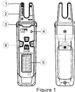
VI. Meter Structure
- NCV sensing end.
- Fork-shaped clamp head: A sensing device to measure AC current
- Finger guard: A safety design to prevent user from touching dangerous area by hand.
- Audible and visual alarm indicator.
- LCD display screen: Display measurement data and functional symbols.
- Functional buttons: Select and switch measurement functions and modes.
VII. Display Symbols
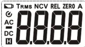
Figure 2
| Symbols | Descriptions |
| H | Data hold prompt |
| Negative reading | |
| Low battery indication | |
| AC/DC | Alternating/Direct current measurement prompt |
| A | Unit of current: Ampere |
| TRMS | True-RMS prompt |
| REL | Relative value prompt |
| ZERO | Zeroing prompt |
| APO prompt | |
| NCV | Non-contact voltage measurement |
VIII. Button Functions
- ⏻: Power on/off the meter. Long press power on, short press power off.
- SELECT: Short press this button to switch between corresponding function ranges.
- HOLD : Data hold/backlight function buttons. Short press to enable /disable the data hold function, the symbol "H" will show on the LCD. Long press about 2 seconds to enable/disable the backlight function.
- REL ZERO : At ACA gear, short press to enable/disable REL measurement function, "REL" will show on the LCD. At DCA gear, short press to enable/disable zeroing function, "ZERO" will show on the LCD
IX. Operating Instructions
1. AC/DC Current Measurement
- Press SELECT button to select AC/DC current measurement.
- Clamp a single current lead to be tested and keep it at the bottom of "U" clamp head.
- Read the measurement value from the LCD. Frequency response: 50Hz\~60Hz.
Note:
- When carrying out current measurement, please be sure that your fingers should not exceed the finger guard.
● The maximum measured AC current shall not exceed 60A.
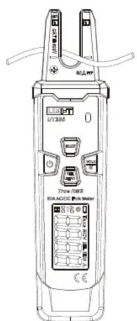
Figure 3
2. NCV Measurement
- Press SELECT button to select NCV measurement function.
- Make the NCV sensing end of the clamp head approach the live AC power cord closely. EF is displayed on the LCD, when voltage is detected, the red NCV indicator light will flash at a frequency of 3Hz and the meter will buzz at a frequency of 3Hz synchronously.
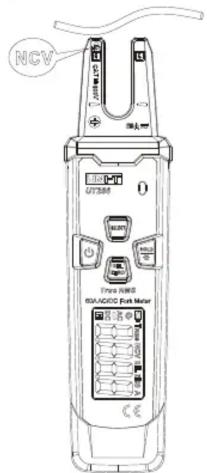
Figure 4
Note:
- If the distance between the sensing end and the measured AC power cord changes, the detected will also change.
- Induced voltage is for reference only. The frequency of induced voltage is applicable to 50Hz\~60Hz.
● Before touching the measured conductor, please measure if the voltage is safe by electro probe or test probe to prevent electric shock.
● Grip the shell of the clamp meter by hand when performing NCV function measurement.
3. Other functions
● APO: The meter will power off automatically to save power if no button is pressed in 30 minutes during measurement. To restart the meter, long press the power button in APO status.
- Hold down SELECT button and press power button, the APO function will be disabled and the buzzer will beep for 5 times (To enable the APO function, restart the meter after it is turned off).
- About 1 minute before the meter powers off automatically, the buzzer will beep for 5 times to indicate that the meter will enter sleep mode. If the meter is not operated in 1 minute by the user the meter will buzz for a long time for once and then enter sleep mode.
● Warning buzzes:
1) When selecting functions through SELECT button, the meter will buzz for once to indicate that position switching is done.
2) When the button is pressed, the meter will buzz for once to indicate the button is active, twice to indicate inactive.
- When the LCD will show "☐", it indicates the user to replace the battery. Under low battery condition, the measuring functions may work, but the measurement accuracy may be affected, please replace the battery as soon as possible.
X. Technical Specifications
Accuracy: ±(a% reading + b digit), one year warranty Ambient temperature and humidity: 23°C±5°C; ≤80%RH
Temperature coefficient: The temperature condition of accuracy is 18° C\~ 28° C, the fluctuation range of ambient temperature stabilizes within ±1° C. If temperature is 18° C or >28° C, the additional temperature coefficient error is: 0.1 x (specified accuracy)/°C.
- AC/DC Current Measurement
| Function | Range | Resolution | Accuracy |
| ACA | 60.0A | 0.1A | (1.0A, 3.0A) : ± (2%+10)(3.0A, 60.0A) : ± (2%+5) |
| DCA | 60.0A | 0.1A | (1.0A, 3.0A) : ± (2%+10)(3.0A, 60.0A) : ± (2%+5) |
Note:
● Accuracy guarantee range: 1A\~60A
● The frequency response of current: 50Hz\~60Hz
XI. Maintenance and Repair
Warning:
Before opening the battery cover of the meter to replace the battery, please be sure that the meter is disconnected with and far away from the measured object.
1. General Maintenance
1) Clean the meter casing with a soft cloth and mild detergent. Do not use abrasives or solvents.
2) If the meter is found abnormal, stop use and send for repair.
3) The maintenance and service must be implemented by qualified professionals or designated departments.
2. Battery Replacement
When low battery symbol "☐" appears on the LCD, please replace the batteries immediately to ensure measurement accuracy. Battery specification: 2×1.5 V AAA.

Figure 5
Operating steps:
1) Set the power switch at "OFF" position.
2) Loosen and remove the screw of the rear cover by screw driver, remove the battery cover, take out the old batteries as figure 5.
3) Replace with two pieces of new batteries (1.5 V AAA).
UNI-T®
UNI-TREND TECHNOLOGY (CHINA) CO., LTD.
No. 6, Gong Ye Bei 1st Road,
Songshan Lake National High-Tech Industrial
Development Zone, Dongguan City,
Guangdong Province, China

- UT256 60A AC/DC FORK METER
- OVERVIEW
- ACCESSORIES
- RULES FOR SAFE OPERATION
- GENERAL CHARACTERISTICS
- METER STRUCTURE
- BUTTON FUNCTIONS
- OPERATING INSTRUCTIONS
- AC/DC CURRENT MEASUREMENT
- NOTE
- NCV MEASUREMENT
- OTHER FUNCTIONS
- ● WARNING BUZZES
- TECHNICAL SPECIFICATIONS
- MAINTENANCE AND REPAIR
- WARNING
- GENERAL MAINTENANCE
- BATTERY REPLACEMENT
- OPERATING STEPS
- UNI-T®
Marque : Uni-T
Modèle : UT256
Catégorie : Multimètre