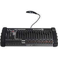
ROCKFORCE 384 - Contrôleur d'éclairage Rockville - Notice d'utilisation et mode d'emploi gratuit
Retrouvez gratuitement la notice de l'appareil ROCKFORCE 384 Rockville au format PDF.


| Type de produit | Subwoofer pour auto |
| Marque | Rockville |
| Modèle | ROCKFORCE 384 |
| Taille du haut-parleur | 12 pouces (305 mm) |
| Impédance | 4 ohms |
| Puissance RMS | 400 watts |
| Puissance crête | 800 watts |
| Réponse en fréquence | 20 Hz - 200 Hz |
| Sensibilité | 90 dB |
| Matériau du cône | Polypropylène renforcé |
| Suspension | Caoutchouc |
| Diamètre de la bobine | 2.5 pouces |
| Aimant | Ferrite |
| Profondeur de montage | 6.7 pouces (170 mm) |
| Diamètre de découpe | 11 pouces (280 mm) |
| Poids | 12.5 kg (27.5 lbs) |
| Dimensions (L x l x h) | 12.6 x 12.6 x 7.1 pouces (320 x 320 x 180 mm) |
| Alimentation | Nécessite un amplificateur externe (non inclus) |
| Fonctions principales | Reproduction des basses fréquences, installation dans un caisson |
| Entretien et nettoyage | Nettoyer avec un chiffon doux sec; éviter les solvants |
| Sécurité | Assurez-vous que l'impédance totale du système ne dépasse pas les spécifications de l'amplificateur |
| Pièces détachées et réparabilité | Bobine de remplacement disponible; consultez le service après-vente |
| Informations générales | Subwoofer conçu pour les systèmes audio de voiture; nécessite un caisson adapté |
FOIRE AUX QUESTIONS - ROCKFORCE 384 Rockville
Questions des utilisateurs sur ROCKFORCE 384 Rockville
0 question sur cet appareil. Repondez a celles que vous connaissez ou posez la votre.
Poser une nouvelle question sur cet appareil
Téléchargez la notice de votre Contrôleur d'éclairage au format PDF gratuitement ! Retrouvez votre notice ROCKFORCE 384 - Rockville et reprennez votre appareil électronique en main. Sur cette page sont publiés tous les documents nécessaires à l'utilisation de votre appareil ROCKFORCE 384 de la marque Rockville.
MODE D'EMPLOI ROCKFORCE 384 Rockville
ROCKVILLE
ROCKFORCE 384
384 CHANNEL LIGHT/FOG DMX LIGHTING CONTROLLER + MIDI CONTROL
OWNER'S MANUAL
ATTENTION: WATCH THIS VIDEO BEFORE FIRST USE!
Who reads manuals?
Scan the QR code or go to rockvillesupport.com/rockforce-384 to access how-to video(s), the owner's manual, and other important information you may need to get the most out of your item.
If you prefer written instructions, please read ahead!
With Rockville you get many options.

Missing items? If you ordered a bundle that includes more than one product and you are missing part of your bundle then it just means your order shipped from two different warehouses. You will receive the remaining items very soon. If you have any concerns or inquiries, feel free to call our customer support center at 1-646-758-0144, 24 hours a day/7 days a week.
Thank you for purchasing this Rockville ROCKFORCE 384 384 Channel Light/Fog DMX Lighting Controller + MIDI Control.
The all new ROCKFORCE 384 is a universal DMX Controller with 384 DMX channels. This controller is easy to use and is designed to work seamlessly with lights from the leading brands. Our DMX controller is top quality and includes easy to understand instructions. This controller functions the same as the other leading brand controllers.
With the ROCKFORCE 384 you can control 24 lights with up to 16 channels per light. In addition there is a 4 bit LED display and built in microphone which can be used to set up automatic modes. A great function we would like to mention is that you can take the program from any light and easily assign it to another light. This added feature provides flexibility and will saves you a ton of time at your next gig!
Although this controller has complex features we were able to design it with users of all experience levels in mind. This controller is so user friendly we gave it to some people who had little to no experience using lighting controllers and they were able to get the hang of it in no time.
Please read this guide carefully for proper use of your Rockville ROCKFORCE 384. Should you need assistance please call our technical help line at 1-646-758-0144, 24 hours a day/7 days a week.
IMPORTANT SAFETY INSTRUCTIONS

- To reduce risk of electric shock, never open the unit. There are no user serviceable parts, refer service to the Rockville service center.
- Do not expose this unit to any kind of moisture.
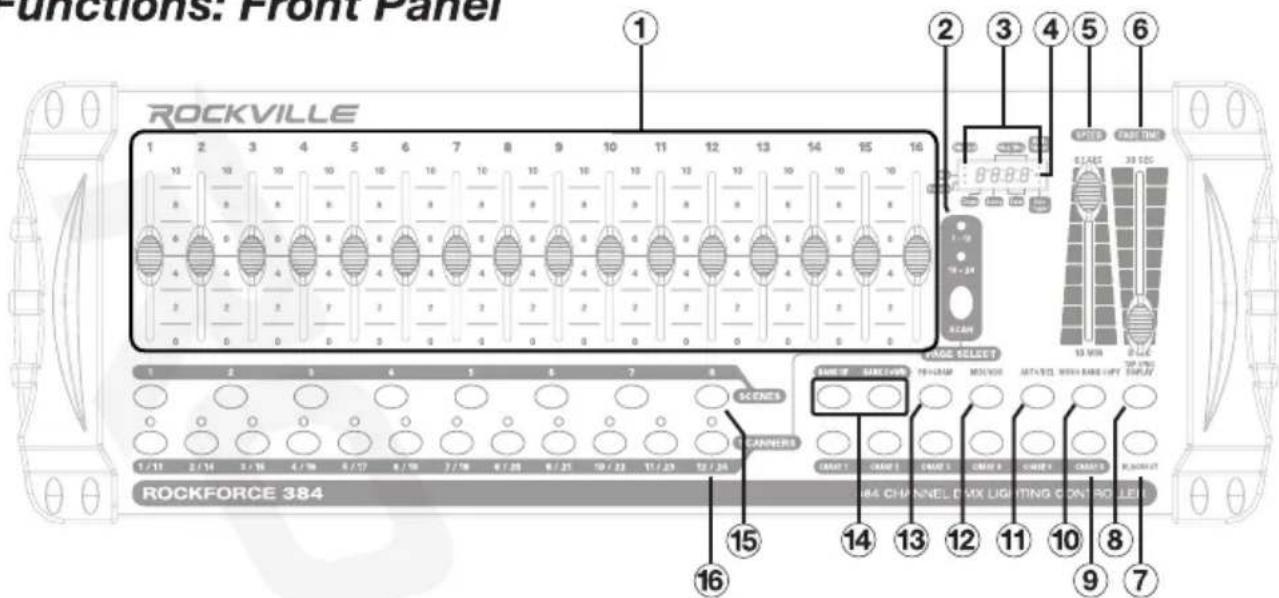
Functions: Front Panel
-
Channel Faders: For adjusting DMX values. Channels 1 – 6 can be adjusted immediately after pressing the respective scanner select button.
-
Scan Select Button: In manual mode, press to toggle between scan levels: 1 - 12/12 - 24.
-
Mode LED Indicators: Provide operating mode status (Blackout, Step, Program, Music trigger, and Auto trigger).
-
LED Display: Shows the active scene and bank number, current chase and step number, fader level settings, and shows the status for various other functions. When adjusting faders the display shows the current level setting. You can select how the level settings are shown (0 – 255 or 0% – 100%) by pushing TAPSYNC/DISPLAY.
-
Speed Fader: Will adjust the speed of scenes or a step within a chase. The display will show the setting in seconds.
-
Fade Time Fader: Adjusts the fade time for scenes and chases. The display will show the setting in seconds.
-
BLACKOUT: Disables all DMX channel output and turns blackout mode on/off.
-
TAPSYNC/DISPLAY: TAPSYNC: Controls the speed of scenes or chases. Press the button at the rate you want the chase or scenes to run at. This is as an alternative to using the SPEED fader. The display will show the result in seconds.
DISPLAY: Switches the display between STEP and BANK. In other modes it switches the output level display to show 0 - 225 or 0% - 100%.
-
Chase Selectors: Selects a chase for programming or playback.
-
MUSIC/BANK Copy: MUSIC: Turns on Music Auto-Run. An internal microphone is used to synchronize chases or scenes to music. There is an indicator on the display showing when music trigger mode is active.
BANK: In program mode pushing this button will copy the contents of one scene bank to another bank.
- AUTO/DEL: AUTO: Activates Auto-Run triggering for chases or scenes. The display has an LED indicator that shows when Auto-Mode is active.
DEL: In program mode this button will delete scenes, complete banks of scenes, chase steps, or complete chases.
- MIDI/ADD: MIDI: Turns MIDI mode on/off and selects the MIDI address. ADD: In program mode pushing the MIDI/ADD button will record a chase step or scene setting on the display showing when music trigger mode is active.
- Program: Used to place the unit in programming mode to create /record scenes and chases. Press and hold for 3 seconds to turn programming mode on /off. An indicator on the display shows when program mode is active. The unit will go into blackout mode when exiting program mode. Push the blackout button (item 14) to turn it off.
- Bank Up/Bank Down Buttons: Selects a scene bank. The third and fourth digits on the display show the currently active bank number (01 – 30). Also used for some chase programming operations.
- Scene Selectors: These buttons allow you to select a scene in the scene bank for programming or playback. The current scene is shown on the display.
- Fixture (Scanner) Selectors: Used to select one or more of the 24 fixtures. Each one is a block of 16 DMX channels. These selectors are used in programming mode and manual mode.
Rear Panel
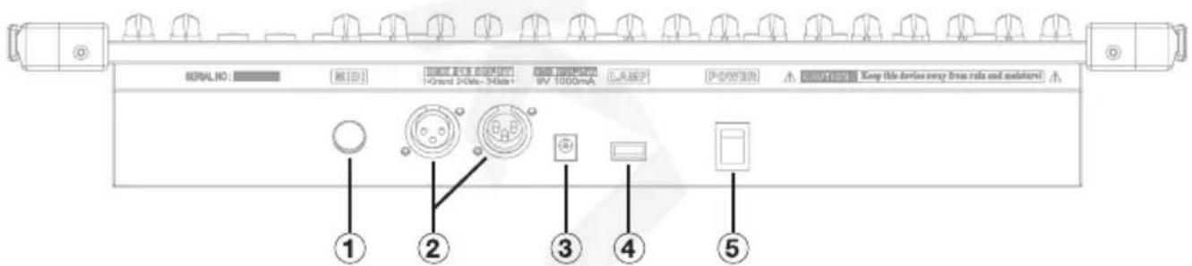
- MIDI IN: For external triggering of banks and chases using a MIDI device.
- DMX OUT: Outputs main control signal to fixtures and other DMX devices.
- DC Input Connector: plug in the external power supply here. DC 9V - 12V, 300mA minimum.
- USB Lamp Socket
- Power Switch: Turns the unit on/off and can be used with other buttons to erase scenes and chases.
Pan and Tilt Channels
Because not all intelligent lighting fixtures are alike or share the same control attributes, the controller allows the user to assign the wheel the correct pan and tilt channel for every individual fixture. All pan/tilt settings can be reassigned to output on a different DMX channel. Press AUTO/DEL buttons to delete the channel assignments.
- Press the desired chase button then press PROGRAM and TAPSYNC/DISPLAY buttons to choose a DMX channel.
- Press a SCANNER button or PAGE SELECT button that represents the fixture whose faders you would like to reassign.
- Move one of the faders to select the pan channel.
- Press the TAPSYNC/DISPLAY button to select pan/tilt.
- Move one of the faders to select the tilt channel.
- Press and hold PROGRAM and TAPSYNC/DISPLAY buttons to exit and save settings. All LEDs will blink indicating completion of the operation.
Resetting the System
To reset the controller to its factory defaults follow the steps below.
- Turn off the unit.
- Press and hold the BANK UP and AUTO/DEL buttons while simultaneously turning on the unit.
Assigning Fade Time
You can choose the board's fade time during scene execution is implemented broadly to all output channels or only to the pan/tilt movement channels. This is relevant because often you will want gobos and colors to change quickly while not affecting the movement of the light.
- Turn off the unit.
- Hold the BLACKOUT and TAPSYNC/DISPLAY buttons simultaneously.
- Turn on the controller.
- Press the TAPSYNC/DISPLAY button to toggle between the two modes (all channels or pan/tilt only).
- Press BLACKOUT and TAPSYNC/DISPLAY buttons to save settings. All LEDs will blink indicating completion of the operation.
Programming Scenes
There are a total of 30 scene banks, each containing 8 scenes which are programmable. Only one bank may be selected at any time. Press and hold PROGRAM button for 3 second to activate program mode. The display PROGRAM indicator will continuously flash while in program mode. Please note that all scene record, edit, delete, and copy functions are done in the program mode.
Recording a Scene
- Position the SPEED and FADE TIME sliders all the way down.
- Select the SCANNERS you wish to include in your scene.
- Adjust the appropriate faders to set the desired output level for each channel.
- Press MIDI/ADD button.
- Choose a BANK, 01 - 30, to change (if necessary).
- Select a SCENES button to store.
- Repeat steps 3 to 7 to record other scenes. You can record up to 8 scenes in a program.
- Exit program mode by pressing and holding down PROGRAM for 3 seconds.
Running a Scene
- Use the BANK UP/BANK DOWN buttons to change program banks if necessary.
- Press the AUTO/DEL button until the AUTO LED is on.
- Adjust the PROGRAM speed via the SPEED Fader and the loop rate via the FADE TIME fader.
- Adjust the chase speed by tapping the TAPSYNC/DISPLAY button twice at a specific rate. The time between the two tops will determine the chase speed. The maximum time is 10 minutes.
Edit a Scene
- Use BANK UP/BANK DOWN buttons to change program banks if necessary.
- Select desired scene within the bank by pushing the corresponding SCENES button (1 - 8).
- Select the fixture(s) to be affected by pushing the associated SCANNERS buttons.
- Adjust the appropriate faders to set the desired output level for each channel.
- Push MIDI/ADD button to prepare to save.
- Push the SCENES button used in step 2 to store the edited scene. When storing is complete, the display will flash briefly.
- De-select any fixtures you have used during editing and exit PROGRAM mode.
Check a Scene
- Select desired scene within the bank by pushing the corresponding SCENES button (1 - 8).
- Press the SCENE button to review each scene individually.
Insert a Scene
- Select desired chase button, 1 - 6.
- Press the TAPSYNC/DISPLAY button switch the LED display to steps view.
- Use BANK UP/BANK DOWN buttons to navigate steps and locate the insert
point of the new scene. The display will read the step number.
- Press MIDI/ADD button to prepare the insert.
- Use the BANK UP/BANK DOWN button to locate the scene.
- Press the SCENE button that corresponds to the scene to be inserted.
- Press MIDI/ADD button to insert the scene. All LEDs on the controller will blink.
Copy a Scene
You can copy the contents of a scene to another scene in the same or different bank.
- Use BANK UP or BANK DOWN to select the bank from which you wish to copy a scene.
- Select desired scene within the bank by pushing it's SCENES button, 1 – 8.
- Push MIDI/ADD to copy the scene.
- Select the bank which you want to copy to using BANK UP or BANK DOWN.
- Push the SCENES button to complete the operation. All LEDs on the controller will flash briefly indication the operation has been completed.
Copy a Bank of Scenes
Copy the entire contents of a scene bank to another bank.
- Select the bank from which you wish to copy by using BANK UP or BANK DOWN.
- Push MIDI/ADD.
- Select the bank to which you wish to copy by using BANK UP or BANK DOWN.
- Push MUSIC/BANK COPY to complete the operation. All LEDs on the controller will flash briefly indication the operation has been completed.
Copy Fixture Settings
You can copy the settings of a fixture to another while programming a scene.
- Hold down the SCANNERS button of the selected fixture.
- Now push the SCANNERS button of the fixture to which the settings will be copied.
- Release the first SCANNER button and then release the second button.
- All SCANNER LED indicators will flash to indicate completion of the copying process.
Delete a Scene
This will set all channels of all fixtures associated with the scene to zero output level.
- Select the bank which contains the scene you want to delete using BANK UP or BANK DOWN.
- Hold down AUTO/DEL and push the SCENES button, 1 – 8, to delete the desired scene. All LEDs will flash briefly indicating that the operation has been completed.
Delete all Scenes in a Bank
- Press and hold the PROGRAM and the BANK DOWN buttons while turning the power off.
- Turn the controller on. This process is irreversible and all scenes will be set to 0.
Clear all Scenes
This will delete all the scenes in all of the banks.
- Turn the unit off. Now turn the power on while simultaneously holding down the PROGRAM and BANK DOWN buttons.
- Keep holding down the buttons until the display flashes briefly indicating that the scenes have been cleared.
Programming Chases
There are 6 user programmable chases and each one includes up to 240 steps. Each chase step consists of a scene which has already been recorded. A chase step can utilize any scene in any bank. Any scene can be used in multiple chase steps and multiple chases.
Record a Chase
- Select a chase, 1 – 6, by pressing the corresponding CHASE button.
- Select the scene bank which contains the scene to be used for the chase step using BANK UP or BANK DOWN.
- Select the scene to insert by pushing its SCENES button (1 - 8).
- Press the MIDI/ADD button to store the chase.
- Repeat steps 2 – 4 as many times as needed to record additional steps in the selected chase. You can record up to 240 steps.
- Press and hold PROGRAM for 3 seconds to exit program mode.
Running a Chase
- Press the CHASE button then press the AUTO/DEL button.
- Adjust the chase speed by tapping the TAPSYNC/DISPLAY button twice at a specific rate. The time between the two tops will determine the chase speed. The maximum time is 10 minutes.
Checking a Chase
- Press the desired CHASE button.
- Press the TAPSYNC/DISPLAY button to switch the LED display to steps.
- Review each scene/step individually by using the BANK UP/BANK DOWN buttons.
Copy a Bank to a Chase
Copy the contents of a bank into a chase.
- Select the chase you wish to copy to by pressing the corresponding CHASE button.
- Use BANK UP or BANK DOWN to select the bank from which you wish to copy.
- Press the MUSIC/BANK COPY button to prepare to copy.
- Push MIDI/ADD and the LEDs will blink indicating that the scene has been copied.
Copy a Scene to a Chase
Copy a scene into a chase.
- Select the chase you wish to copy to by pressing the corresponding CHASE button.
- Use BANK UP or BANK DOWN to select the bank that contains the scene to be copied.
- Press the SCENE button that corresponds to the scene to be copied.
- Push MIDI/ADD and the LEDs will blink indicating that the scene has been copied.
Insert Step into a Chase
- Select a chase, 1 – 6, by pressing the corresponding CHASE button.
- Press TAPSYNC/DISPLAY and the display will show the step.
- Use BANK UP or BANK DOWN buttons to navigate steps and locate the insert point of the new scene.
-
Press MIDI/ADD button to prepare the insert.
-
Press the SCENES button, 1 – 8, to select the scene you wish to insert. If the scene you wish to insert is in a different bank, use BANK UP or BANK DOWN to select the desired bank.
- Push MIDI/ADD to insert the scene. All the LEDs will blink indicating that the scene has been copied.
Delete a Scene/Step in a Chase
- Select a chase, 1 - 6, that contains the scene to be deleted.
- Press TAPSYNC/DISPLAY button to switch the LED display to steps.
- Use BANK UP or BANK DOWN to advance to the scene/step you wish to delete.
- Push AUTO/DEL button to delete the step/scene. All LEDs will blink.
Delete a Complete Chase
- Press and hold the CHASE button corresponding to the chase you wish to delete.
- Now also press AUTO/DELETE. All LEDs will blink.
- Release both buttons.
Clear all Chases
This sequence will delete all the steps of all the chases. It does not clear scenes.
- Turn the unit off.
- Turn the power on while simultaneously pressing and holding the BANK DOWN and AUTO/DEL buttons.
- Keep holding down the buttons until all LEDs flash indicating that the chases have been cleared.
Operating Scenes
When the ROCKFORCE 384 is turned on, it defaults to manual scene mode with bank 1, scene 1 active.
Manual Mode
The manual mode allows direct control of all scanners. You are able to move them and change attributes by using the channel fader. All changes made while in Manual mode are temporary and will not be recorded.
- Press the AUTO/DEL button repeatedly until the MANUAL LED is lit.
- Select a SCANNER button.
- Move the faders to change fixture attributes. Press the TAPSYNC/DISPLAY button to toggle the output indicator in the LED display between DMX values (0 - 255) and percentage (0 - 100%).
Review Scene or Chase
This instruction assumes that you have already recorded scenes and chases on the controller. Otherwise skip section and go to programming.
Scene Review:
- Select any one of the 30 banks by pressing the BANK UP/BANK DOWN buttons.
- Select a SCENE button, 1 – 8, to review.
- Move wheel and faders to change fixture attributes.
Chase Review:
- Select any one of the 6 CHASE buttons.
- Press the TAPSYNC/DISPLAY button to view the step number on the display.
- Press the BANK UP/BANK DOWN buttons to review all the scenes in a chase.
Run a Bank of Scenes Automatically
The scene Auto-Run function will continuously cycle through a bank of scenes. The operator can control the speed and scene fade time. To adjust the speed use the TAPSYNC button or the SPEED fader. To control the fade time use the FADE TIME fader. Scenes can also be synchronized to music or MIDI note triggering.
- Select the appropriate scene bank using BANK UP or BANK DOWN.
- Push AUTO/DEL. This will cause the scene Auto-Run to begin cycling and the AUTO TRIGGER indicator on the display will light.
- Adjust the speed and fade time as needed. If you set your speed faster than the fade time then the scenes will advance before the fade is complete.
- You can switch to another bank at any time using BANK UP and BANK DOWN.
- To stop Auto-Run press the AUTO/DEL button. The AUTO TRIGGER indicator on the display will go OFF.
Run Scenes Automatically with Music Sync
This unit has an internal microphone which can be used to Auto-Run scenes with music synchronization.
Scene Music Auto-Run
10 Press MUSIC/BANK COPY. The MUSIC TRIGGER indicator on the display will light.
- To switch to a different scene bank use BANK UP or BANK DOWN.
- You can adjust the duration time using the FADE TIME fader.
- To stop Music Auto-Run press the MUSIC/BANK COPY button.
Operating Chases
Chases can be run in Manual, Auto-Run, and Music Auto-Run modes.
Manual Chase Operation
This is used to manually step through a chase. It is done in program mode and is useful when creating or editing chases.
- Press and hold the PROGRAM button to enter program mode. The display PROGRAM indicator will continuously flash while in program mode.
- Select a chase, 1 - 6, by pushing the appropriate CHASE button.
- Press TAP/SYNC and the display will show the chase and step numbers. The display STEP indicator will light.
- Use the BANK UP and BANK DOWN buttons to cycle through the chase steps.
- When finished, press and hold PROGRAM for 3 seconds to exit the program mode.
Run a Chase Automatically
The chase Auto-Run function will continuously cycle through a chase. Multiple chases can be run together and in the order selected.
- Select a chase, 1 – 6, by pressing the appropriate CHASE button. You can select more than one.
- Push AUTO/DEL. The AUTO TRIGGER indicator in the display will light and the chase(s) will run.
- Adjust the chase speed by tapping the TAPSYNC/DISPLAY button twice at a specific rate. The time between the two tops will determine the chase speed. The maximum time is 10 minutes.
- To stop chase Auto-Run press the AUTO/DEL button. The AUTO TRIGGER indicator on the display will go OFF. If all the chases are turned off before you turn off Auto-Run, the unit will default to the scene Auto-Run in the last accessed scene bank.
Chase Music Auto-Run
- Press MUSIC/BANK COPY. The MUSIC TRIGGER LED on the display will light.
- Select a chase, 1 – 6, by pressing the appropriate CHASE button. Or you can select several CHASE buttons in sequence and all selected chases will loop in the order in which they were selected.
- You can adjust the duration time using the FADE TIME fader.
- To stop Music Auto-Run press the AUTO/DEL button. The MUSIC TRIGGER indicator on the display will go OFF.
MIDI Control Activation
The controller will only respond to MIDI commands on the MIDI channel which is set to full stop. The ROCKFORCE 384 uses MIDI "Note on" commands to execute scene and chase function. All other MIDI instructions are ignored. You may have to use a MIDI keyboard to send the correct notes. To stop a chase, send the blackout on note.
- Press and hold the MIDI/ADD button for about to 3 seconds.
- Select MIDI control channel, 1 – 16, via the BANK UP/BANK DOWN buttons to set.
- Press and hold the MIDI/ADD button to save settings.
- To release MIDI control, press any other button except the BANK buttons during step 2.
The table below shows the functions which can be controlled by MIDI.
| MIDI NOTE | FUNCTION |
| 00 – 07 | Bank 1 Scenes 1 – 8 ON/OFF |
| 08 – 15 | Bank 2 Scenes 1 – 8 ON/OFF |
| 16 – 23 | Bank 3 Scenes 1 – 8 ON/OFF |
| 24 – 31 | Bank 4 Scenes 1 – 8 ON/OFF |
| 32 – 39 | Bank 5 Scenes 1 – 8 ON/OFF |
| 40 – 47 | Bank 6 Scenes 1 – 8 ON/OFF |
| 48 – 55 | Bank 7 Scenes 1 – 8 ON/OFF |
| 56 – 63 | Bank 8 Scenes 1 – 8 ON/OFF |
| 64 – 71 | Bank 9 Scenes 1 – 8 ON/OFF |
| 72 – 79 | Bank 10 Scenes 1 – 8 ON/OFF |
| 80 – 87 | Bank 11 Scenes 1 – 8 ON/OFF |
| 88 – 95 | Bank 12 Scenes 1 – 8 ON/OFF |
| 96 – 103 | Bank 13 Scenes 1 – 8 ON/OFF |
| 104 – 111 | Bank 14 Scenes 1 – 8 ON/OFF |
| 112 – 119 | Bank 15 Scenes 1 – 8 ON/OFF |
| 120 – 125 | Chases 1 – 6 ON/OFF |
| 126 | Blackout |
Fixture Channel Assignments
The controller is programmed to control 32 channels of DMX per fixture, therefore the fixtures you wish to control with the corresponding SCANNER buttons on the unit, must be spaced 16 channels apart.
| FIXTURE | DEFAULT DMX STARTING ADDRESS | BINARY DIP SWITCH SETTINGS SWITCH TO THE “ON POSITION” | FIXTURE | DEFAULT DMX STARTING ADDRESS | BINARY DIP SWITCH SETTINGS SWITCH TO THE “ON POSITION” |
| 1 | 1 – 16 | 1 | 13 | 193 – 208 | 1, 7, 8 |
| 2 | 17 – 32 | 1, 5 | 14 | 209 – 224 | 1, 5, 7, 8 |
| 3 | 33 – 48 | 1, 64 | 15 | 225 – 240 | 1, 6, 7, 8 |
| 4 | 49 – 64 | 1, 5, 6 | 16 | 241 – 256 | 1, 5, 6, 7, 8 |
| 5 | 65 – 80 | 1, 7 | 17 | 257 – 272 | 1, 9 |
| 6 | 81 – 96 | 1, 5, 7 | 18 | 273 – 288 | 1, 5, 9 |
| 7 | 97 – 112 | 1, 6, 7 | 19 | 289 – 304 | 1, 6, 9 |
| 8 | 113 – 128 | 1, 5, 6, 7 | 20 | 305 – 320 | 1, 5, 6, 9 |
| 9 | 129 – 144 | 1, 8 | 21 | 321 – 336 | 1, 7, 9 |
| 10 | 145 – 160 | 1, 5, 8 | 22 | 337 – 352 | 1, 5, 7, 9 |
| 11 | 161 – 176 | 1, 6, 8 | 23 | 353 – 368 | 1, 6, 7, 9 |
| 12 | 177 – 192 | 1, 5, 6, 8 | 24 | 369 | 1, 5, 6, 7, 9 |
Each fixture must be set to accommodate the DMX assignment. This is usually done using DIP switches on the fixture. Refer to the individual owner's manual of the fixture for exact instructions. This information may also appear on a chart on the fixture. If you set multiple fixtures to the same addresses then they will respond to the controller as one fixture.
Fixture Functions
You will need to know which channel within a fixture is assigned to each fixture function (pan, tilt, color, dimming, etc.). This information is normally given in the fixture's owner's manual.
Operating Fixtures Manually
To manually control a fixture push the corresponding fixture button in the Scanners section. This will activate the LED indicator and enable the channel faders. If you are using a fixture with more than 8 channels, press the PAGE A/B button to access the other channels. Multiple fixtures can be selected and controlled together. To de-select a fixture, press the corresponding button.
DMX Connections
There are 512 channels in a DMX-512 connection. Channels may be assigned in any manner. A fixture capable of receiving DMX-512 will require one or a number of sequential channels. The user must assign a starting address on the fixture that indicates the first channel reserved in the controller. There are many different types of DMX controllable fixtures and they will all vary in the total number of channels required. Choosing a start address should be planned in advance. Channels should never overlap. If they do, this will result in erratic operation of the fixtures whose starting address is set incorrectly. You can however, control
multiple fixtures of the same type using the same starting address as long as the intended result is that of uniform movement or operation. In other words, the fixtures will be slaved together and all respond exactly the same.
When using multiple DMX devices, they should be connected together as a chain of devices. The devices should be wired in a daisy chain fashion, meaning the control cable will go from the controller to the first fixture and then to other fixtures. Most fixtures have a DMX IN and a DMX OUT port for this purpose. Do not split the control cable into a multiple run star arrangement with a cable running from the controller directly to each fixture.
DMX Connector Pin Assignments
There are two types of DMX cables, 3-pin or 5-pin, and they feature XLR type connectors. This unit transmits from a 3-pin female connector on the back edge of the unit. If your fixtures use 5 pin connectors, we recommend you acquire a 3-pin male XLR to 5-pin female XLR adapter. Some fixtures use a reversed signal scheme. This means the DATA - and DATA + pins are reversed. This unit features a reversing switch on the back so as to accommodate those types of fixtures. The table below shows the pin assignments for both normal and reversed operation.
| PIN | NORMAL | REVERSED |
| 1 | DMX Common | DMX Common |
| 2 | DMX DATA - | DMX DATA + |
| 3 | DMX DATA + | DMX DATA - |
| 4 | Not used | Not used |
| 5 | Not used | Not used |
XLR Connection
DMX OUTPUT
XLR MOUNTING SOCKET

- Ground
- Signal (−)
- Signal (+)
DMX OUTPUT
XLR MOUNTING PLUG

- Ground
- Signal (−)
- Signal (+)
DMX Termination
In controller mode, the last fixture of a DMX chain has to be “terminated”. This prevents electrical noise from disturbing and corrupting the DMX control signals. To terminate the last fixture solder a 1/4 Watt, 120 Ohm resistor across the DATA - and DATA + wires. The connections are illustrated below. If you are only connecting a few fixtures which are close together and use a short run to the controller, you maybe able to operate without a terminator.
DMX Termination Diagram


If you wish to connect DMX controllers with other XLR outputs, you need to use and adapter cable.

DMX Dip Switch Quick Reference Chart
| Dip Switch Position | |||||||||||||||||||
| DMX DIP SWITCH SET0=OFF1=ONX=OFF or ON | #9 | 0 | 0 | 0 | 0 | 0 | 0 | 0 | 0 | 1 | 1 | 1 | 1 | 1 | 1 | ||||
| #8 | 0 | 0 | 0 | 0 | 1 | 1 | 1 | 1 | 0 | 0 | 0 | 0 | 1 | 1 | |||||
| #7 | 0 | 0 | 1 | 1 | 0 | 0 | 1 | 1 | 0 | 0 | 1 | 1 | 0 | 1 | |||||
| #6 | 0 | 1 | 0 | 1 | 0 | 1 | 0 | 1 | 0 | 1 | 0 | 1 | 0 | 1 | |||||
| #1 | #2 | #3 | #4 | #5 | |||||||||||||||
| 0 | 0 | 0 | 0 | 0 | 32 | 64 | 96 | 128 | 160 | 192 | 224 | 256 | 288 | 320 | 352 | 384 | 416 | ||
| 1 | 0 | 0 | 0 | 0 | 1 | 33 | 65 | 97 | 129 | 161 | 193 | 225 | 257 | 289 | 321 | 353 | 385 | 417 | |
| 0 | 1 | 0 | 0 | 0 | 2 | 34 | 66 | 98 | 130 | 162 | 194 | 226 | 258 | 290 | 322 | 354 | 386 | 418 | |
| 1 | 1 | 0 | 0 | 0 | 3 | 35 | 67 | 99 | 131 | 163 | 195 | 227 | 259 | 291 | 323 | 355 | 387 | 419 | |
| 0 | 0 | 1 | 0 | 0 | 4 | 36 | 68 | 100 | 132 | 164 | 196 | 228 | 260 | 292 | 324 | 356 | 388 | 420 | |
| 1 | 0 | 1 | 0 | 0 | 5 | 37 | 69 | 101 | 133 | 165 | 197 | 229 | 261 | 293 | 325 | 357 | 389 | 421 | |
| 0 | 1 | 1 | 0 | 0 | 6 | 38 | 70 | 102 | 134 | 166 | 198 | 230 | 262 | 294 | 326 | 358 | 390 | 422 | |
| 1 | 1 | 1 | 0 | 0 | 7 | 39 | 71 | 103 | 135 | 167 | 199 | 231 | 263 | 295 | 327 | 359 | 391 | 423 | |
| 0 | 0 | 0 | 1 | 0 | 8 | 40 | 72 | 104 | 136 | 168 | 200 | 232 | 264 | 296 | 328 | 360 | 392 | 424 | |
| 1 | 0 | 0 | 1 | 0 | 9 | 41 | 73 | 105 | 137 | 169 | 201 | 233 | 265 | 297 | 329 | 361 | 393 | 425 | |
| 0 | 1 | 0 | 1 | 0 | 10 | 42 | 74 | 106 | 138 | 170 | 202 | 234 | 266 | 298 | 330 | 362 | 394 | 426 | |
| 1 | 1 | 0 | 1 | 0 | 11 | 43 | 75 | 107 | 139 | 171 | 203 | 235 | 267 | 299 | 331 | 363 | 395 | 427 | |
| 0 | 0 | 1 | 1 | 0 | 12 | 44 | 76 | 108 | 140 | 172 | 204 | 236 | 268 | 300 | 332 | 364 | 396 | 428 | |
| 1 | 0 | 1 | 1 | 0 | 13 | 45 | 77 | 109 | 141 | 173 | 205 | 237 | 269 | 301 | 333 | 365 | 397 | 429 | |
| 0 | 1 | 1 | 1 | 0 | 14 | 46 | 78 | 110 | 142 | 174 | 206 | 238 | 270 | 302 | 334 | 366 | 398 | 430 | |
| 1 | 1 | 1 | 1 | 0 | 15 | 47 | 79 | 111 | 143 | 175 | 207 | 239 | 271 | 303 | 335 | 367 | 399 | 431 | |
| 0 | 0 | 0 | 0 | 1 | 16 | 48 | 80 | 112 | 144 | 176 | 208 | 240 | 272 | 304 | 336 | 368 | 400 | 432 | |
| 1 | 0 | 0 | 0 | 1 | 17 | 49 | 81 | 113 | 145 | 177 | 209 | 241 | 273 | 305 | 337 | 369 | 401 | 433 | |
| 0 | 1 | 0 | 0 | 1 | 18 | 50 | 82 | 114 | 146 | 178 | 210 | 242 | 274 | 306 | 338 | 370 | 402 | 434 | |
| 1 | 1 | 0 | 0 | 1 | 19 | 51 | 83 | 115 | 147 | 179 | 211 | 243 | 275 | 307 | 339 | 371 | 403 | 435 | |
| 0 | 0 | 1 | 0 | 1 | 20 | 52 | 84 | 116 | 148 | 180 | 212 | 244 | 276 | 308 | 340 | 372 | 404 | 436 | |
| 1 | 0 | 1 | 0 | 1 | 21 | 53 | 85 | 117 | 149 | 181 | 213 | 245 | 277 | 309 | 341 | 373 | 405 | 437 | |
| 0 | 1 | 1 | 0 | 1 | 22 | 54 | 86 | 118 | 150 | 182 | 214 | 246 | 278 | 310 | 342 | 374 | 406 | 438 | |
| 1 | 1 | 1 | 0 | 1 | 23 | 55 | 87 | 119 | 151 | 183 | 215 | 247 | 279 | 311 | 343 | 375 | 407 | 439 | |
| 0 | 0 | 0 | 1 | 1 | 24 | 56 | 88 | 120 | 152 | 184 | 216 | 248 | 280 | 312 | 344 | 376 | 408 | 440 | |
| 1 | 0 | 0 | 1 | 1 | 25 | 57 | 89 | 121 | 153 | 185 | 217 | 249 | 281 | 313 | 345 | 377 | 409 | 441 | |
| 0 | 1 | 0 | 1 | 1 | 26 | 58 | 90 | 122 | 154 | 186 | 218 | 250 | 282 | 314 | 346 | 378 | 410 | 442 | |
| 1 | 1 | 0 | 1 | 1 | 27 | 59 | 91 | 123 | 155 | 187 | 219 | 251 | 283 | 315 | 347 | 379 | 411 | 443 | |
| 0 | 0 | 1 | 1 | 1 | 28 | 60 | 92 | 124 | 156 | 188 | 220 | 252 | 284 | 316 | 348 | 380 | 412 | 444 | |
| 1 | 0 | 1 | 1 | 1 | 29 | 61 | 93 | 125 | 157 | 189 | 221 | 253 | 285 | 317 | 349 | 381 | 413 | 445 | |
| 0 | 1 | 1 | 1 | 1 | 30 | 62 | 94 | 126 | 158 | 190 | 222 | 254 | 286 | 318 | 350 | 382 | 414 | 446 | |
| 1 | 1 | 1 | 1 | 1 | 31 | 63 | 95 | 127 | 159 | 191 | 223 | 255 | 287 | 319 | 351 | 383 | 415 | 447 | |
Dip Switch Position
DMX Address
Glossary of Common Terms
Blackout: a state where all lighting fixture's light output is set to) or off, usually on a temporary basis.
DMX-512: an industry standard digital communication protocol used in entertainment lighting equipment.
FIXTURES: refers to your lighting instrument or other device such as a fog machine or dimmer which you can control.
Programs: are numerous scenes stacked one after another. It can be programmed as either a single scene or multiple scenes in sequence.
Scenes: are static lighting states.
Sliders: also known as faders.
Chases: can also be called programs. A chase consists of numerous scenes stacked one after another.
Scanner: refers to a lighting instrument with a pan and tilt mirror; however, in the ILLS-CON controller it can be used to control any DMX-512 compatible device as a generic fixture.
MIDI: is a standard for representing musical information in a digital format. An MIDI input would provide external triggering of scenes using an MIDI device such as a MIDI keyboard.
Stand Alone: refers to a fixture's ability to function independently of an external controller and usually in sync to music, due to a built-in microphone.
Fade: a slider used to adjust the time between scenes within a chase.
Speed: a slider that affects the amount of time a scene will hold its state. It is also known as a "wait time".
Shutter: a mechanical device in the lighting fixture that allows you to block the lights path. It is often used to lessen the intensity of the light output and to strobe.
Patching: refers to the process of assigning fixtures a DMX channel.
Playbacks: can be either scenes or chases that are directly called to execution by the user. A playback can also be considered program memory that can be recalled during a show.
Features and Specifications
• Rockville ROCKFORCE 384 Universal DMX-512 controller with MIDI controls
• 24 Intelligent lights of up to 16 channels each
• 30 Banks of 8 programmable scenes
• 384 DMX channels of control
• 6 Programmable chases of 240 scenes
- Record up to 6 chases with fade time and speeds
• 16 Sliders for direct control of channels
• MIDI control over banks, chases and blackout
• Built-in microphone for music mode
• Automatic mode program controlled by speed and fade time sliders
- Blackout master button
- Reversible DMX channels allows fixture to react opposite to others in a chase
- Manual override allows you to grab any fixture on the fly
• Built-in microphone for music triggering
• MIDI control over banks, chases, and blackout
- DMX polarity selector
• Power failure memory
- 4 bit LED display
- DMX in/out: 3 pin XLR
• LED goose neck lamp
• Power Supply: 110 – 240V, 50/60Hz (DC 9V – 12V)
• Electric current: > 500mA
• Power Consumption: 10W
• Control Signal: DMX512
• Control Channels: 384CH
- Item weight: 5.4 lbs.
• Product dimensions: 20.71" x 7.28" x 3.15"
POCKVILLE
ROCKVILLE

- ROCKVILLE
- ROCKFORCE 384
- WHO READS MANUALS
- IMPORTANT SAFETY INSTRUCTIONS
- FUNCTIONS: FRONT PANEL
- REAR PANEL
- PAN AND TILT CHANNELS
- RESETTING THE SYSTEM
- ASSIGNING FADE TIME
- PROGRAMMING SCENES
- RECORDING A SCENE
- RUNNING A SCENE
- EDIT A SCENE
- CHECK A SCENE
- INSERT A SCENE
- COPY A SCENE
- COPY A BANK OF SCENES
- COPY FIXTURE SETTINGS
- DELETE A SCENE
- DELETE ALL SCENES IN A BANK
- CLEAR ALL SCENES
- PROGRAMMING CHASES
- RECORD A CHASE
- RUNNING A CHASE
- CHECKING A CHASE
- COPY A BANK TO A CHASE
- COPY A SCENE TO A CHASE
- INSERT STEP INTO A CHASE
- DELETE A SCENE/STEP IN A CHASE
- DELETE A COMPLETE CHASE
- CLEAR ALL CHASES
- OPERATING SCENES
- MANUAL MODE
- REVIEW SCENE OR CHASE
- SCENE REVIEW
- CHASE REVIEW
- RUN A BANK OF SCENES AUTOMATICALLY
- RUN SCENES AUTOMATICALLY WITH MUSIC SYNC
- SCENE MUSIC AUTO-RUN
- OPERATING CHASES
- MANUAL CHASE OPERATION
- RUN A CHASE AUTOMATICALLY
- CHASE MUSIC AUTO-RUN
- MIDI CONTROL ACTIVATION
- FIXTURE CHANNEL ASSIGNMENTS
- FIXTURE FUNCTIONS
- OPERATING FIXTURES MANUALLY
- DMX CONNECTIONS
- DMX CONNECTOR PIN ASSIGNMENTS
- XLR CONNECTION
- DMX TERMINATION
- DMX TERMINATION DIAGRAM
- GLOSSARY OF COMMON TERMS
- FEATURES AND SPECIFICATIONS
Marque : Rockville
Modèle : ROCKFORCE 384
Catégorie : Contrôleur d'éclairage