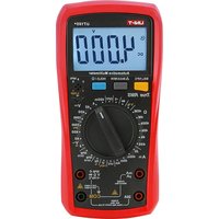
UT107+ - Multimètre Uni-T - Notice d'utilisation et mode d'emploi gratuit
Retrouvez gratuitement la notice de l'appareil UT107+ Uni-T au format PDF.


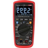
| Type de produit | Multimètre numérique |
| Marque | Uni-T |
| Modèle | UT107+ |
| Affichage | Écran LCD rétroéclairé, 1999 points |
| Tension continue | 200 mV / 2 V / 20 V / 200 V / 600 V, ±0.5 % |
| Tension alternative | 200 V / 600 V, ±1.2 % |
| Courant continu | 200 µA / 2 mA / 20 mA / 200 mA / 10 A, ±1 % |
| Courant alternatif | 200 µA / 2 mA / 20 mA / 200 mA / 10 A, ±1.2 % |
| Résistance | 200 Ω / 2 kΩ / 20 kΩ / 200 kΩ / 2 MΩ / 20 MΩ / 200 MΩ, ±0.8 % |
| Capacité | 2 nF / 20 nF / 200 nF / 2 µF / 20 µF / 200 µF, ±4 % |
| Fréquence | 2 kHz / 20 kHz / 200 kHz, ±1.5 % |
| Température | -20 °C à 1000 °C (avec thermocouple type K) |
| Test de diode | Oui |
| Test de continuité | Avec signal sonore (buzzer) |
| Alimentation | Pile 9 V (type 6F22) |
| Dimensions | 190 × 88 × 50 mm |
| Poids | Environ 310 g (avec pile) |
| Accessoires fournis | Pointes de test, thermocouple, pile 9 V, manuel d'utilisation |
| Indice de protection | CAT II 600 V, CAT I 1000 V |
| Entretien et nettoyage | Nettoyer avec un chiffon humide. Ne pas utiliser de solvants. Retirer la pile en cas de non utilisation prolongée. |
| Sécurité | Conforme CE, RoHS. Utilisation uniquement sur circuits de catégorie spécifiée. |
| Garantie | 2 ans (selon conditions du fabricant) |
FOIRE AUX QUESTIONS - UT107+ Uni-T
Questions des utilisateurs sur UT107+ Uni-T
0 question sur cet appareil. Repondez a celles que vous connaissez ou posez la votre.
Poser une nouvelle question sur cet appareil
Téléchargez la notice de votre Multimètre au format PDF gratuitement ! Retrouvez votre notice UT107+ - Uni-T et reprennez votre appareil électronique en main. Sur cette page sont publiés tous les documents nécessaires à l'utilisation de votre appareil UT107+ de la marque Uni-T.
MODE D'EMPLOI UT107+ Uni-T

P/N:110401110972X
UNI-T


UT105+/UT107+
Automotive Multimeter
User Manual
Preface
Thank you for purchasing this brand new product. In order to use this product safely and correctly, please read this manual thoroughly, especially the safety notes.
After reading this manual, it is recommended to keep the manual at an easily accessible place, preferably close to the device, for future reference.
Limited Warranty and Liability
Uni-Trend guarantees that the product is free from any defect in material and workmanship within one year from the purchase date. This warranty does not apply to damages caused by accident, negligence, misuse, modification, contamination or improper handling. The dealer shall not be entitled to give any other warranty on behalf of Uni-Trend. If you need warranty service within the warranty period, please contact your seller directly.
Uni-Trend will not be responsible for any special, indirect, incidental or subsequent damage or loss caused by using this device.
Table of Contents
- Overview 4
- Accessories 5
- Rules for Safe Operation 5
- Safety Guides for Automotive Servicing ---- 7
- Electrical Symbols 10
- General Specifications 11
- The Meter Structure 12
- Rotary Switch 13
- Functional Buttons 14
- Display Symbols 15
- Instructions for Measurement Operation ---- 17
- Technical Specifications 36
- Maintenance and Repair 47
I. Overview
This manual includes relevant safety information and warning information, please read the relevant contents carefully and follow all warnings and precautions strictly. Warning: Please read "Rules for Safe Operation" carefully before use.
UT105+/UT107+ is a handheld new-energy automotive multimeter with high reliability and high safety. The meter adopts micro-controlled data processing technology with high-resolution A/D converter. The meter has an extra large digital LCD display, full overload protection and unique outlook design, which makes it more superior in performance and safer in use. UT105+/UT107+ has multiple features such as intelligentization, high accuracy, high performance, multifunctional, and more. The meter can be used to measure or test the following parameters:
- AC/DC voltage
• AC voltage frequency
• VFC
• RPM - Pulse width (mS) (UT107+)
• DWELL
• NPN and PNP
• 12V automotive battery (UT107+) - AC/DC current
- Resistance
• Capacitance (UT107+) - Continuity
• Diode
The meters also have other functions including data hold, max/min, relative, low voltage indication, audiovisual alarm, backlight and APO.
II. Accessories
Open the package box and take out the meter. Check the following items carefully to see any missing or damaged part.
User manual 1 piece
Test lead 1 pair
K-type thermocouple sensor 1 piece
1.5V AAA battery 1 pair
III. Rules for Safe Operation
The meter is designed and produced strictly in accordance with GB4793, IEC61010-1, CAT II 1000V, CAT III 600V, Double Insulation and Pollution Degree 2 Standards. Use the meter as specified in the manual, otherwise the protection provided by the meter may be compromised.
-
Check the clamp meter and test leads before use, guard against any damage or abnormal phenomenon. If any abnormal condition was found: bare test lead, damaged insulation, no display in LCD or others, please do not use it. It is forbidden to use the meter prior to having battery cover in place, or otherwise there will be electric shock.
-
The damaged test leads must be replaced by new ones with same models or specifications.
-
Do not contact the bare wire, connector, unused input terminal or the circuit being measured when the meter is in operation.
-
Be careful in measuring voltage higher than AC/DC 30V, keep finger within the scope of finger protection position of test lead to avoid electric shock.
-
Set the function range switch at the maximum range position if the scope of measured value couldn't be defined.
-
Refrain from applying voltage over the rating value indicated at the meter between terminals or between any terminal and grounding.
-
Function switch shall be set at the correct position prior to measurement. The connection between test lead and circuit being measured must be disconnected before converting the function switch. It is forbidden to perform gear conversion in measurement to guard against damage to the meter.
-
Prior to measurement of on-line resistance and diode or the circuit on-off measurement, the power of circuits being measured shall be powered off and all capacitors shall be completely discharged.
-
Before performing current measurement, please turn off the current to be measured and check if the fuse is good. To prevent the risk of electric discharge, only after the meter is connected to the circuit reliably can the current to be measured be turned on.
- Refrain from storing or using the clamp meter in the explosive and flammable environment with high temperature, high humidity and strong electromagnetic field.
- Refrain from changing the internal wiring in the clamp meter to guard against damage to the meter and danger.
- When LCD display shows the icon "☐", it is required to replace the battery in time to ensure the measurement accuracy.
- Power off the meter in time when measurement is completed. Take out battery when clamp meter is not in use for a long time.
IV. Safety Guides for Automotive Servicing
To prevent an accident from causing any personal injury or any damage to an automobile or any of its meters, please read the following safety guidelines and testing procedure in earnest:
● Wear protective eyeglasses which meet safety requirements.
- Operate the automobile in a well-ventilated place so as to prevent the inhalation of any toxic tail gas.
- Keep your own tools and testing instruments far from all the heating components of the operating engine.
- Ensure that the automobile has stopped (automatic transmission) or put into neutral gear (manual transmission) and be sure that it is equipped with brakes and the wheels have been locked.
- Do not place any tool on the automotive battery which will cause a short circuit of the electrodes and in turn lead to any personal injury or damage to a tool or battery.
● Smoking or striking a light near the automobile is prohibited. - Pay attention to ignition coil, ignition lead and spark plug socket because these components are provided with high voltages when the automobile is operating.
- To connect or cut off an electronic component, close the ignition lock.
- Pay attention to the automotive producer's cautions, notes and servicing procedures.
Warning
As some automobiles are installed with safety air bags, you must pay attention to the cautions in the automotive servicing manual when you are working around the components and wiring of the air bags, or any carelessness will open an air bag, resulting in some personal injury. Note that the air bag will also be opened for a few minutes after the ignition lock is closed (or even when the automotive battery is cut off), which is driven by the special energy reserve.
All the information, explanations and detailed descriptions in the operational manual have originated from the industrial information recently published. It is impossible to prove the accuracy and completeness of the information, of which we shall not be responsible for the assumption.
- The data of automotive servicing manual have originated from the automotive servicing information:
(1). Contact the local distributors of automotive components.
(2). Contact the local retailers of automotive components.
(3). Contact the local libraries to look up any book for the proofreading of your automotive servicing manual so as to provide you with the latest information. - Before the diagnosis of any trouble, open the engine hood to make a thorough visual inspection. You will find the causes for many of your problems to be solved, which will save you a lot of time.
(1). Has the automobile recently been serviced? Has the same problem sometimes occurred where the trouble lies?
(2). Do not try to find any short cut. Check the hoses and leads where it is probably very difficult to find out where any trouble lies.
(3). Check any trouble with the air purifier or pipeline system.
(4). Check any damage to any sensor or the driving gear.
(5). Check the ignition lead: any breakage of any terminal, crack on any spark plug or breakage at the insulation of the ignition lead.
(6). Check all the vacuum hoses: any right line, shrinkage, bend, crack, fracture or damage.
(7). Check the leads: any connection of sharp edges, connection of hot surfaces (such as exhaust manifold), shrinkage, burn or scratch at the insulation or right line connection.
(8). Check the connection of circuit: any pin corrosion, bend or damage, inappropriate connection position or damaged electrode lead.
V. Electrical Symbols
| A | Risk of high voltage | Double insulated | |
| DC (Direct Current) | Grounding | ||
| Fuse | Warning prompt | ||
| Low battery | Continuity buzzer | ||
| AC (Alternating Current) | |||
VI. General Specifications
- Maximum voltage between signal input terminal and COM terminal: Refer to the instruction of protective voltage input at each range.
- µ A mA input terminal is set with fuse: (CE) 600mA H 250V quick-acting fuse, 6×32mm.
- 16A input terminal is set with fuse: (CE) 16A H 250V quick-acting fuse, 6 × 32mm .
- Display count: 4000 (Ut105+), 6000 (Ut107+)
- Display updates 2 or 3 times per second
- Range: Manual
- Polarity display: Auto
• Overrange indicator: OL - Low battery indication: ≤2.4±0.2V approximately
- Operating temperature: 0°C\~40°C (32°F\~104°F)
- Storage temperature: -10°C\~50°C (14°F\~122°F)
- Relative humidity: ≤75% (0°C\~30°C), ≤50% (30°C\~40°C)
- Operating altitude: ≤2000m
- EMC: In accordance with EN61326-1:2006; EN61326-2-2:2006
● Power supply: 2×1.5V AAA battery (3V)
• External dimension: 183mm x 88mm x 56mm
● Weight: About 348g (including batteries) - Category rating: IEC 61010-1: CAT II 1000V, CAT III 600V
VII. The Meter Structure

Figure 1
- LCD display
- Functional buttons
- Rotary switch
- Input terminal
- Terminal for triode
- Holster
- kick stand
VIII. Rotary Switch
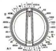
Figure 2

UT107+
| Position | Function description |
| V= | DC voltage measurement |
| V~ | AC voltage measurement |
| ACV_VFC | VFC measurement (ACV) |
| Hz/% | Frequency/Duty ratio measurement |
| RPM | Engine speed measurement |
| Pulse width (mS) | Ignition time measurement (UT107+ only) |
| Dwell | Dwell angle measurement |
| hFE | Triode measurement |
| 12V | 12V automotive battery measurement (UT107+ only) |
| mA≈ | AC/DC mA current measurement |
| A≈ | AC/DC 20A current measurement |
| Ω | Resistance measurement |
| +(- | Capacitance measurement (UT107+ only) |
| °C/°F | Celsius/Fahrenheit degree measurement |
| → | Diode measurement |
| -)) | Continuity measurement |
IX. Functional Buttons


Figure 3
Operation instruction:
Short press: Press the button for <2 seconds.
Long press: Press the button for ≥2 seconds.
| Buttons | Description |
| HOLD / ☉ | 1. Short press to enter or exit data hold mode.2. Long press to turn on/off the backlight. |
| Δ MAX/MIN | 1. Short press to enter or exit relative mode, which is only applicable to DCmV, DCV, ACV_VFC, Ω, °C/°F, CAP (UT107+), DCmA, DCA, ACmA, ACA.2. Long press to enter max/min mode, short press MAX/MIN button to view maximum/ minimum value in sequence, "MAX" and "MIN" will show on the LCD in sequence. To exit max/min mode, long press MAX/ MIN button again or switch the gear (only for DCmV, DCV, ACV_VFC, Ω, DCmA, DCA, ACmA, ACA). In max/min mode, the APO function will be disabled. |
| SEL/VFC | 1. Short press to select the functions marked in yellow color at the rotary switch.2. Long press to enter or exit VFC (only for ACV 1000V).Press and hold SELECT button and turn the rotary switch to start the meter, the buzzer will make sound for 4 times, then the meter will enter non-sleeping state. |
X. Display Symbols

Figure 4
| 1 | Auto power off |
| 2 | Dangerous voltage |
| 3 | Alternating current measurement |
| 4 | Direct current measurement |
| 5 | Data hold |
| 6 | Low battery |
| 7 | Auto range measurement |
| 8 | Variable frequency voltage |
| 9 | Maximum/minimum measurement |
| 10 | Relative value measurement |
| 11 | Rotation speed of engine |
| 12 | Ignition pulse width |
| 13 | Number of cylinder of engine |
| 14 | Engine stroke |
| 15 | Resistance unit/frequency unit/duty cycle unit |
| 16 | Diode measurement |
| 17 | Continuity measurement |
| 18 | Voltage unit/current unit/capacitance unit |
| 19 | Temperature measurement |
| 20 | Amplification factor of triode |
| 21 | Dwell angle measurement |
XI. Instructions for Measurement Operation
Please check the built-in AAA 1.5V batteries firstly, if the battery is low after the meter is turned on, the LCD will show "←", please replace the batteries to ensure the test accuracy. Please pay special attention to the warning sign "Δ" near the terminal of test lead, this sign "Δ" warns that the voltage or current under test shall not exceed the specified value to assure measurement safety!
1. AC/DC Voltage Testing
1) Connect the red test lead to "V" terminal, and black to "COM".

Figure 5
2) Turn the rotary switch to AC/DC voltage gear, connect test leads in parallel to the power or the load to be measured.
3) Read the measured voltage from the LCD directly.
4) At AC 1000V gear, long press SELECT to ACV_VFC function, composite sinusoidal signal generated by inverter and variable-frequency motor can be measured through VFC function, as shown below. Long press SELECT to exit ACV_VFC function.

5) When measuring ACV or ACV_VFC voltage, short press SELECT to switch to frequency measurement of voltage, read the frequency of measured voltage from the LCD. For frequency measurement of voltage, the amplitude of input voltage is required to be greater than 10% of the maximum range, please refer to "Technical Specifications" for more details.
Note:
- Input impedance is about 10MΩ, measuring high-impedance circuit may cause measurement error. In most cases, as the impedance of circuit is less than 10KΩ, the error (0.1% or less) is negligible.
-
Do not measure the input voltage exceeding the range, otherwise, correct reading cannot be obtained and it may damage the meter and harm the user. If the range of measured voltage is not known before performing measurement, set the rotary switch to the highest gear, and then select lower gear according to the actual reading (If the LCD shows "OL", that means overrange and indicates to increase the range).
-
Do not input voltage over 1000V. It is possible to measure higher voltage, but the protection provided by the meter may be compromised.
- Pay special attention to avoid electric shock when measuring high voltage.
- Before using the meter, a known voltage can be measured to verify if the product functions are good.
- The high-voltage alarming symbol will be displayed if the measured voltage is >30V (AC/DC); the buzzer will make alarming sound continuously and the LED will be on if the measured voltage is >1000V (AC/DC).
- Disconnect the test leads with the measured circuit after all measurement operations are completed.
2. Frequency/Duty Cycle Testing
1) Connect the red test lead to "V" terminal, and black to "COM".
2) Turn the rotary switch to Hz/% gear, connect the test leads in parallel to the signal source to be measured.
3) Short press SELECT to switch between frequency and duty cycle.
4) Read the frequency or the duty cycle from the LCD.

Note:
- As the degree of signal attenuation changes in different gears and ranges, the amplitude and the range of input signal may be different in different gears and ranges. Please refer to "Technical Specifications" for more details.
- Disconnect the test leads with the measured circuit after all measurement operations are completed.
3. Rotational Speed Testing (RPM)
RPM means "Revolutions Per Minute" of the main shaft of engine.
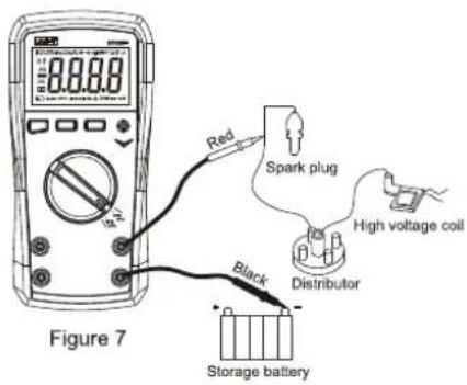
1) For Ut105+, turn the rotary switch to "RPM 2STR" or "RPM 4STR"; for UT107+, turn the rotary switch to "RPM", short press SELECT to select a suitable engine stroke to measure the RPM of engine.
2) Connect the red test lead to "V" terminal, and black to "COM". Connect the test end as figure 7.
- If the automobile adopts "Distributorless Ignition System" (DIS), connect the red test lead to the signal wire of TACH (Tachometer), the signal wire is connected to the DIS module of automotive engine, please refer to the automotive maintenance manual for the specific location of the signal wire.
- If the automobile adopts "Distribution Ignition System", connect the red test lead to the negative terminal of primary winding of ignition coil, please refer to the automotive maintenance manual for the specific location.
3) Connect the black test lead to the good grounding terminal of the automobile.
4) Measure the engine RPM when the engine is started or running, read the engine RPM from the LCD.
Note:
- The range of rotational speed for two-stroke measurement is 300\~19999 RPM; the range of rotational speed for four-stroke measurement is 600\~19999 RPM.
- Disconnect the test leads with the measured circuit after all measurement operations are completed.
4. Pulse Width Testing (mS-PULSE) (UT107+ only)
Pulse width refers to the duration of high level, there are different meanings for pulse width in different fields. In automotive field, the pulse width measurement is used in the fuel injection system, electromagnetic valve controlled by hybrid fuel, idle air control motor, etc. Figure 8 shows the pulse width measurement of fuel injection system.
1) Turn the rotary switch to "mS".
2) Connect the red test lead to "V" terminal, and black to "COM". Connect the test end as figure 8.
3) Connect the black test lead to the grounding wire of oil nozzle or to the good grounding terminal of the automobile.
4) Connect the red test lead to the input wire of electromagnetic valve of oil nozzle.
5) Start the engine. Read the time of pulse width from the LCD directly.
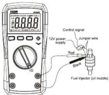
Figure 8
Note:
- Disconnect the test leads with the measured circuit after all measurement operations are completed.
23
5. Engine Dwell Testing
It was very important to measure the dwell angle of cutout switch of ignition system. The measurement of dwell angle refers to the duration that the cutout switch keeps in off state when the cam rotates. Nowadays, automobiles use electronic ignition, the adjustment of dwell angle is not needed. The measurement of dwell angle can also be applied in hybrid-control solenoid. (i.e. GM feedback carburetors). Figure 9 shows the measurement of dwell angle of engine.
1) Turn the rotary switch to "Dwell" gear, short press SELECT to select suitable number of cylinder.
2) Connect the red test lead to "V" terminal, and black to "COM". Connect the test end as figure 9.
- To measure the cutout switch of ignition system, please connect the red test lead the negative terminal of primary winding of ignition coil. (Refer to the automotive maintenance manual for the specific location)
- To measure GM feedback carburetor, please connect the red test lead to the grounding terminal of solenoid or computer drive of solenoid. (Refer to the automotive maintenance manual for the specific location)
- To measure the dwell angle of any ON/OFF device, please connect the red test lead to the end installed with ON/OFF switch.
3) Connect the black test lead to the good grounding terminal of the automobile.
4) Measure the ignition dwell when the engine is started or running, read the ignition dwell from the LCD directly.

Figure 9
Note:
- Disconnect the test leads with the measured circuit after all measurement operations are completed.
- Dwell angle differs from ignition angle. Dwell angle refers to the duration from connection to disconnection of the primary coil, that is the pulse width of ignition control pulse. Ignition angle refers to the rotation angle of crankshaft from the start of ignition to the end point at which the piston rises.
25
6. Triode Amplification Factor Testing (hFE)
1) Turn the rotary switch to "hFE".
2) When inserting base (B), emitter (E), collector (C) of the triode (PNP or NPN type) to the 4-pin socket accordingly, the LCD will show the approximate value of hFE of the triode.

Figure 10
7. 12V Battery Testing (UT107+ only)
1) Turn the rotary switch to "12V".
2) Insert the red test lead to "mA" terminal, and black to "COM". The polarity of red test lead is "+" the polarity of black test lead is "-". Connect the test leads to the electrodes of storage battery in parallel.
26
3) Read the voltage of storage battery from the LCD directly.

Figure 11
Note:
- Disconnect the electrodes of storage battery with the circuit before measurement to avoid that the measurement result is affected.
- Disconnect the test leads with the measured circuit after all measurement operations are completed, especially for the measurement of large current.
27
8. AC/DC Current Testing
1) Turn the rotary switch to "mA" or "A" range, press SELECT to select desired AC/DC current.
2) Insert the red test lead to "mA" or "A" terminal, and black to "COM". Connect the test leads with the loop to be measured.
3) Read the measured current from the LCD directly, the measured AC current is T-RMS value.
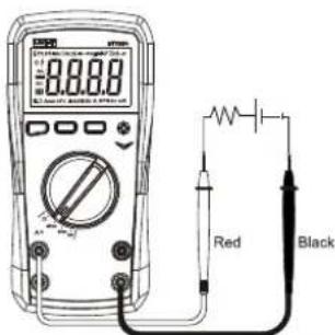
Figure 12
Note:
- Check if the fuse of the meter is good before measurement, the checking methods are as below:
1) Check 600mA fuse: Turn the rotary switch to "MΩ" gear, short-circuit the V terminal and the mA terminal. If the displayed resistance is about 1 MΩ, the fuse is good, otherwise the fuse may be damaged.
2) Check 16A fuse: Turn the rotary switch to "Ω" gear, short-circuit the V terminal and the A terminal. If the displayed resistance is about 0.0Ω, the fuse is good, otherwise the fuse may be damaged.
- Before connecting the meter with the loop to be measured, please turn off the current in the loop, otherwise there will be a risk of electric spark.
- Correct input terminal and functional gear should be selected, if the current cannot be estimated, please start measurement from the high range. For the measurement of current over 10A, the measurement time should be less than 10 seconds and the measurement interval should be more than 15 minutes.
- When the measured current is greater than 10A, the buzzer will make alarm sound continuously and the LED will flash. When the measured current is greater than 20A, OL will be displayed.
- When the test lead is inserted into the current input terminal, do not connect the test lead to any circuit in parallel, otherwise the fuse will be blown and the meter will be damage.
- After all measurement operations are completed, turn off the measured current source before disconnecting the test lead with the measured circuit, especially for the measurement of large current.
9. Resistance Testing
1) Turn the rotary switch to "Ω", "KΩ" or "MΩ" range.
2) Insert the red test lead to "V" terminal, and black to "COM", connect the test lead to the resistor.
29
3) Read the measured resistance from the LCD directly.

Figure 13
Note:
- If the measured resistance is open or the resistance exceeds the maximum range, the LCD will show "OL".
- Before measuring resistance on line, turn off all the powers in the measured circuit and discharge all capacitors completely to ensure accurate measurement.
-
If the resistance of test lead at short circuit is less than 0.5Ω , please check the looseness for the test lead and other reasons.
-
It is normal to take seconds to steady the reading for the measurement of resistance over 1MΩ.
- Do not input voltage over 30V AC/DC to avoid personal injury.
- Disconnect the test leads with the measured circuit after all measurement operations are completed.
10. Capacitance Testing (UT107+ only)
1) Turn the rotary switch to "100mF", connect the test leads to the measured capacitor in parallel.
2) Insert the red test lead to "V" terminal, and black to "COM", connect the test leads to the measured capacitor in parallel.
3) Read the capacitance loaded in the measured circuit from the LCD directly.

Figure 14
Note:
- It is recommended that REL mode is used for the measurement of capacitance less than 100nF.
- If the measured capacitor is open or the capacitance exceeds the maximum range, the LCD will show "OL".
- Before performing measurement, discharge all capacitors completely (especially for capacitor with high voltage) to avoid damage to the meter and personal injury.
- Disconnect the test leads with the measured capacitor after all measurement operations are completed.
11. Temperature Measurement
1) Turn the rotary switch to "F°C", "OL" will be displayed on the LCD. When the test lead is short-circuited, the ambient temperature will be displayed.
2) Insert the K-type thermocouple sensor to corresponding terminal as figure 15, the temperature probe will detect the measured surface, after seconds, read the temperature of measured surface from the LCD directly.
3) To read Fahrenheit temperature, press SELECT to switch from "°C" to "°F".

Figure 15
Note:
- Do not connect the thermocouple to a live circuit to avoid electric shock.
- Do not input voltage over 30V DC/AC to avoid personal injury.
- Remove the temperature probe after all measurement operations are completed.
12. Continuity Testing
1) Tum the rotary switch to “••” for UT105+; turn the rotary switch to “▶••” for UT107+, short press SELECT to select continuity measurement.
2) Insert the red test lead to "V" terminal, and black to "COM", connect the test leads to the both loaded ends of measured circuit in parallel. If the resistance between the both measured ends is 10Ω , the continuity of the circuit is considered to be in good condition, the buzzer will make sounds continuously and the LED will flash.
33
If the resistance between the both measured ends is 50Ω , the circuit is considered to be open, the buzzer will make no sound.
3) Read the resistance loaded in the measured circuit from the LCD directly.
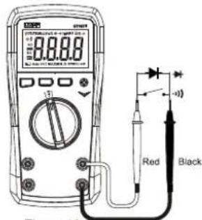
Figure 16
- Before measuring continuity on line, turn off all the powers in the measured circuit and discharge all capacitors completely.
- The open-circuit voltage is about 3V for continuity measurement.
- Do not input voltage over 30V AC/DC to avoid personal injury.
- Disconnect the test leads with the measured circuit after all measurement operations are completed.
13. Diode Testing
1) Turn the rotary switch to “→” for Ut105+; turn the rotary switch to “→…” for UT107+, short press SELECT to select diode measurement.
2) Insert the red test lead to "V" terminal, and black to "COM". The polarity of red test lead is "+" , the polarity of black test lead is "-" . Connect red test lead to the positive pole of diode, connect black test lead to the negative pole of diode.
3) Read the approximate value of forward voltage of PN junction from the LCD. The normal voltage of silicone PN junction is about 0.5\~0.8V generally.

Note:
- If the test is normal, the buzzer will make a beep sound. If short-circuited, the buzzer will make sound continuously and the LED will flash.
- "OL" will be displayer when the measured diode is open or the polarity is reversed.
35
- Before measuring diode on line, turn off all the powers in the measured circuit and discharge all capacitors completely.
- The open-circuit voltage is about 3.0V for diode test.
- Do not input voltage over 30V AC/DC to avoid personal injury.
- Disconnect the test leads with the measured circuit after all measurement operations are completed.
XII. Technical specifications
Accuracy: ±(a% reading + b digit), one year warranty Ambient temperature: 23°C±5°C Relative temperature: <75%
Note:
- Temperature condition of accuracy measurement: 18°C\~28°C, the fluctuation range of ambient temperature stabilizes within ±1°C. If temperature is <18°C or >28°C the additional temperature coefficient error is: 0.1 x (specified accuracy)/°C.
1. DC Voltage
UT107+
| Range | Resolution | Accuracy | Overload Protection |
| 600.0mV | 0.1mV | ±(0.5%+5) | 1000V AC/DC |
| 6.000V | 1mV | ±(0.5%+3) | |
| 60.00V | 10mV | ±(0.7%+3) | |
| 600.0V | 100mV | ||
| 1000V | 1V |
36
UT105+
| Range | Resolution | Accuracy | Overload Protection |
| 400.0mV | 0.1mV | ±(0.5%+5) | 1000V AC/DC |
| 4.000V | 1mV | ±(0.5%+3) | |
| 40.00V | 10mV | ±(0.7%+3) | |
| 400.0V | 100mV | ||
| 1000V | 1V |
* Input impedance: About 10MΩ
* Accuracy guarantee: 2%\~100% of the range
- AC Voltage
UT107+
| Range | Resolution | Accuracy | Overload Protection |
| 6.000V | 1mV | ±(1.0%+3) | 1000V AC/DC |
| 60.00V | 10mV | ±(0.8%+3) | |
| 600.0V | 100mV | ||
| 1000V | 1V | ±(1.0%+10) |
UT105+
| Range | Resolution | Accuracy | Overload Protection |
| 4.000V | 1mV | ±(1.0%+3) | 1000V AC/DC |
| 40.00V | 10mV | ±(0.8%+3) | |
| 400.0V | 100mV | ||
| 1000V | 1V | ±(1.0%+10) |
* Display the TRMS of sine wave
* Input impedance: About 10MΩ
* Frequency response: 40Hz\~400Hz
* Accuracy guarantee: 5\~100% of range, short circuit allows least significant digit ≤5.
* The AC crest factor of non-sinusoidal wave could be 3.0 at 3000 counts and must be ≤1.5 at 6000 counts. Add an error for the crest factor:
a. Add 3% for the accuracy if the crest factor is 1.0\~2.0 b. Add 5% for the accuracy if the crest factor is 2.0\~2.5 c. Add 7% for the accuracy if the crest factor is 2.5\~3.0
* The condition to switch to frequency measurement: The input amplitude of voltage should be greater than 10% of maximum range, the frequency accuracy is ±(1%+3)
- VFC
| Range | Resolution | Accuracy | Overload Protection |
| 1000V | 1V | ± (2.0%+10) | 1000V AC/DC |
* Display: TRMS of sine wave
* Input impedance: About 10MΩ
* Frequency response: 40Hz\~200Hz
* Accuracy guarantee: 5\~100% of range, short circuit allows least significant digit <5.
* The AC crest factor of non-sinusoidal wave could be 3.0 at 3000 counts and must be ≤1.5 at 6000 counts. Add an error for the crest factor:
a. Add 3% for the accuracy if the crest factor is 1.0\~2.0
b. Add 5% for the accuracy if the crest factor is 2.0\~2.5
c. Add 7% for the accuracy if the crest factor is 2.5\~3.0
* The 3db frequency of VFC is about 2.5KHz.
* The condition to switch to frequency measurement: The input amplitude should be greater than 10% of maximum range, the frequency accuracy is ±(1%+3)
4. Frequency/Duty Cycle (Hz/%)
| Range | Resolution | Accuracy | Overload Protection |
| 10.00Hz~10.00MHz | 0.01Hz~0.01MHz | ±(0.1%+5) | 1000V AC/DC |
| 10%-90% | 0.1 | ±(2.6%+7) |
* Input amplitude:
≤100kHz: 200mVrms ≤Input amplitude ≤30Vrms
100kHz\~1MHz: 600mVrms ≤ Input amplitude ≤30Vrms
1MHz: 1Vrms ≤Input amplitude ≤30Vrms
* Duty cycle:
10%\~90% : Applicable to square wave at 10Hz\~1kHz. 30%\~70% : Applicable to square wave at 1KHz\~10kHz.
Input amplitude: 2Vpp ≤ Input amplitude ≤ 20Vpp
5. Rotational Speed of Engine
| Range | Resolution | Accuracy | Overload Protection |
| 2STR | 1RPM | ±(3.0%+5) | 1000V AC/DC |
| 4STR | ±(3.0%+3) |
* Input signal:
Duty cycle: 5%\~95%
Amplitude: 1Vpp\~20Vpp
* Two-stroke rotational speed range is 300\~19999RPM; four-stroke rotational speed range is 600\~19999RPM.
• Measure the rotational speed through electromagnetic induction device: Invention patent: "The Device and Method to Measure the Rotational Speed of Engine Through Electromagnetic Induction Device" (Patent number: CN201710720041.1).
39
6. Pulse Width (mS PULSE) (UT107+ only)
| Range | Resolution | Accuracy | Overload Protection |
| 999.9mS | 0.1mS | ±(1.5%+10) | 1000V AC/DC |
* Input signal:
Pulse frequency: 1Hz\~<1kHz
Pulse width: ≥0.5mS
Amplitude: 2Vpp\~20Vpp
7. Ignition Dwell
| Range | Resolution | Accuracy | Overload Protection |
| 1CYL | 0.1" | ±(3.0%+5) | 1000V AC/DC |
| 2CYL | |||
| 3CYL | |||
| 4CYL | |||
| 5CYL | |||
| 6CYL | |||
| 8CYL |
* Duty cycle: 5%\~95%
* Amplitude: 10Vpp\~20Vpp
* Frequency: 5Hz\~340Hz
(Rotational speed: 300\~19999RPM)
- Triode (hFE)
| Range | Resolution | Description | Overload Protection |
| 1000 β | 1 β | (NPN/PNP)Vce about 1.2V, Ib0 about 10μA | 1000V AC/DC |
* Display: Approximate value of hFE of measured triode.
- 12V Battery Measurement (UT107+ only)
| Range | Resolution | Accuracy | Overload Protection |
| 12.00V | 0.01V | ± (2.5%+3) | FF 600mA H 250V |
* Load resistance: 240Ω (Discharge resistance)
- DC Current
UT107+
| Range | Resolution | Accuracy | Overload Protection |
| 6.000mA | 0.001mA | ±(0.8%+8) | F600mA H 250V |
| 60.00mA | 0.01mA | ±(1.2%+5) | |
| 600.0mA | 0.1mA | ||
| 20.00A | 10mA | ±(2.0%+5) | F16A H 250V |
UT105+
| Range | Resolution | Accuracy | Overload Protection |
| 4.000mA | 0.001mA | ±(0.8%+8) | F600mA H 250V |
| 40.00mA | 0.01mA | ±(1.2%+5) | |
| 400.0mA | 0.1mA | ||
| 20.00A | 10mA | ±(2.0%+5) | F16A H 250V |
* Accuracy guarantee: 2%\~100% of range
* Allow least significant digit < 2 at open circuit. Note: For measurement of current at 10A\~20A, the measurement time is ≤10 seconds, the measurement interval is ≥15 seconds.
- AC Current UT107+
| Range | Resolution | Accuracy | Overload Protection |
| 6.000mA | 0.001mA | ±(1.0%+8) | F600mA H 250V |
| 60.00mA | 0.01mA | ±(2.0%+3) | |
| 600.0mA | 0.1mA | ||
| 20.00A | 10mA | ±(3.0%+5) | F16A H 250V |
UT105+
| Range | Resolution | Accuracy | Overload Protection |
| 4.000mA | 0.001mA | ±(1.0%+8) | F600mA H 250V |
| 40.00mA | 0.01mA | ±(2.0%+3) | |
| 400.0mA | 0.1mA | ||
| 20.00A | 10mA | ±(3.0%+5) | F16A H 250V |
* Display: TRMS of sine wave
* Accuracy guarantee: 5\~100% of range
* Allow least significant digit <2 at open circuit
* The AC crest factor of non-sinusoidal wave could be 3.0 at 3000 counts and must be ≤1.5 at 6000 counts. Add an error for the crest factor:
a. Add 3% for the accuracy if the crest factor is 1.0\~2.0
b. Add 5% for the accuracy if the crest factor is 2.0\~2.5
c. Add 7% for the accuracy if the crest factor is 2.5\~3.0
Note: For measurement of current at 10A\~20A, the measurement time is ≤10 seconds, the measurement interval is ≥15 seconds.
12. Resistance
UT107+
| Range | Resolution | Accuracy | Overload Protection |
| 600.0Ω | 0.1Ω | ±(0.8%+5) | 1000V AC/DC |
| 6.000kΩ | 1Ω | ±(0.8%+3) | |
| 60.00kΩ | 10Ω | ||
| 600.0kΩ | 100Ω | ||
| 60.00MΩ | 10kΩ | ±(2.0%+5) |
UT105+
| Range | Resolution | Accuracy | Overload Protection |
| 400.0Ω | 0.1Ω | ±(0.8%+5) | 1000V AC/DC |
| 4.000kΩ | 1Ω | ±(0.8%+3) | |
| 40.00kΩ | 10Ω | ||
| 400.0kΩ | 100Ω | ||
| 4.000MΩ | 1kΩ | ||
| 40.00MΩ | 10kΩ | ±(2.0%+5) |
* For 400Ω/600Ω: Measured result = displayed value - resistance of shorted test leads
* Open-circuit voltage: About 1V
* Accuracy guarantee: 5%\~100% of range
- Capacitance (UT107+ only)
| Range | Resolution | Accuracy | Overload Protection |
| 6.000nF | 0.001nF | ±(4.0%+25) | 1000V AC/DC |
| 60.00nF | 0.01nF | ±(4.0%+10) | |
| 600.0nF | 0.1nF | ||
| 6.000uF | 1nF | ±(3.0%+10) | |
| 60.00uF | 10nF | ||
| 600.0uF | 100nF | ||
| 6.000mF | 0.001mf | ±(5.0%+10) | |
| 60.00mF | 0.01mf | ±(10.0%) | |
| 100.0mF | 0.1mf |
* Auto range (Least significant digit is allowed to be 25 at open circuit)
* Accuracy guarantee: 5%\~100% of range
* It is recommended to measure in REL mode for capacitance ≤100nF.
* "OL" will be displayed if the capacitance input is ≥100.0mF.
- Temperature
| Range | Resolution | Accuracy | Overload Protection |
| -40°C~100°C | 1°C | ±(1%+3) | 1000V AC/DC |
| 100°C~1000°C | 1°C | ±(2%+3) | |
| -40°F~212°F | 1°F | ±(1.5%+5) | |
| 212°F~1832°F | 1°F | ±(2.5%+5) |
* Ambient temperature will be displayed at short circuit.
* "OL" will be displayed at open circuit.
15. Continuity
UT107+
| Range | Resolution | Accuracy | Overload Protection |
| 600.0Ω | 0.1Ω | Broken circuit: Resistance ≥50.0Ω, no beepWell-connected circuit: Resistance ≤10.0Ω, the buzzer beeps | 1000VAC/DC |
UT105+
| Range | Resolution | Accuracy | Overload Protection |
| 400.0Ω | 0.1Ω | Broken circuit: Resistance ≥50.0Ω, no beepWell-connected circuit: Resistance ≤10.0Ω, the buzzer beeps | 1000VAC/DC |
* Open-circuit voltage is about 1V
* The buzzer may or may not beep at 10.0Ω\~50.0Ω
* The LED will flash at the same time that the buzzer beeps.
- Diode
UT107+
| Range | Resolution | Accuracy | Overload Protection |
| 6.000V | 0.001V | Open-circuit voltage: About 3V Measurable PN junction: Forward voltage drop 3V For the silicon PN junction, the normal value is generally about 0.5~0.8V. | 1000V AC/DC |
UT105+
| Range | Resolution | Accuracy | Overload Protection |
| 4.000V | 0.001V | Open-circuit voltage: About 3V Measurable PN junction: Forward voltage drop 3V For the silicon PN junction, the normal value is generally about 0.5~0.8V. | 1000V AC/DC |
* The buzzer will beep for once if the test is normal.
* If short circuit occurs, the buzzer will beep for a long time and the LED will flash.
* Least significant digit is allowed to be about 5 at short circuit.
XIII. Maintenance and Repair
UT105+/UT107+ is a smart advanced precision multimeter, please do not attempt to repair this meter except authorized professionals qualified in test approach of performance calibration.
The meter adopts automatic calibration technology, unless replaceable components specified, all components and parts cannot be replaced to avoid deviation of technical specifications.
1. General Maintenance
1) Clean the meter casing with a soft cloth and mild detergent. Do not use abrasives or solvents.
2) If the meter is found abnormal, stop use and send for repair.
3) The maintenance and service must be implemented by qualified professionals or designated departments.
4) Turn off the power of the meter when not used, remove the batteries when the meter is not used for a long time.
5) Do not store the meter in the environment with high moisture, high temperature and strong electromagnetic field.
2. Battery/Fuse Replacement
1) When low battery symbol "☐" appears on the LCD, please replace the batteries immediately to ensure measurement accuracy. Battery specification: 1.5 V AAA×2 (3V).
2) If the display does not react at all when performing current measurement, please check if the built-in fuse is blown. Check the fuse as below:
a. For 600mA fuse: Turn the rotary switch to "MΩ" gear, short-circuit "V" terminal and "mA" terminal through the test lead, if the displayed resistance is about 1MΩ, the fuse is good, otherwise the fuse may be damaged.
b. For 16A fuse: Turn the rotary switch to "Ω" gear, short-circuit "V" terminal and "A" terminal through the test lead, if the displayed resistance is about 0.0Ω, the fuse is good, otherwise the fuse may be damaged.
If the fuse is blown, please replace it immediately according to the original specifications.
Fuse specifications:
- mA range: F1 φ 6×32mm F600mA H 250V
● 20A range: F2 φ 6×32mm F16A H 250V
Operating steps:
1) Turn off the meter and remove the test leads from the input terminals.
2) Battery replacement: Loosen the screw of the battery compartment, remove the battery cover and replace batteries according to the polarity indication.
3) Loosen the two screws fixing the rear cover, remove the rear cover and replace the blown fuse.

Figure 18
The contents of this manual are subject to change without prior notice!
UNI-T.
UNI-TREND TECHNOLOGY (CHINA) CO., LTD.
No. 6, Gong Ye Bei 1st Road,
Songshan Lake National High-Tech Industrial
Development Zone, Dongguan City.
Guangdong Province, China

- UNI-T
- PREFACE
- LIMITED WARRANTY AND LIABILITY
- TABLE OF CONTENTS
- OVERVIEW
- ACCESSORIES
- RULES FOR SAFE OPERATION
- SAFETY GUIDES FOR AUTOMOTIVE SERVICING
- WARNING
- GENERAL SPECIFICATIONS
- FUNCTIONAL BUTTONS
- INSTRUCTIONS FOR MEASUREMENT OPERATION
- AC/DC VOLTAGE TESTING
- NOTE
- FREQUENCY/DUTY CYCLE TESTING
- ROTATIONAL SPEED TESTING (RPM)
- PULSE WIDTH TESTING (MS-PULSE) (UT107+ ONLY)
- ENGINE DWELL TESTING
- TRIODE AMPLIFICATION FACTOR TESTING (HFE)
- 12V BATTERY TESTING (UT107+ ONLY)
- AC/DC CURRENT TESTING
- RESISTANCE TESTING
- CAPACITANCE TESTING (UT107+ ONLY)
- TEMPERATURE MEASUREMENT
- CONTINUITY TESTING
- DIODE TESTING
- TECHNICAL SPECIFICATIONS
- DC VOLTAGE
- FREQUENCY/DUTY CYCLE (HZ/%)
- ROTATIONAL SPEED OF ENGINE
- PULSE WIDTH (MS PULSE) (UT107+ ONLY)
- IGNITION DWELL
- RESISTANCE
- CONTINUITY
- MAINTENANCE AND REPAIR
- GENERAL MAINTENANCE
- BATTERY/FUSE REPLACEMENT
- OPERATING STEPS
Marque : Uni-T
Modèle : UT107+
Catégorie : Multimètre