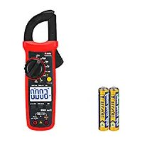
UT202A+ - Multimètre Uni-T - Notice d'utilisation et mode d'emploi gratuit
Retrouvez gratuitement la notice de l'appareil UT202A+ Uni-T au format PDF.


| Type de produit | Multimètre numérique |
| Marque | Uni-T |
| Modèle | UT202A+ |
| Dimensions (L x l x h) | 150 x 75 x 30 mm |
| Poids | 200 g (avec pile) |
| Alimentation | Pile 9 V (type 6F22) |
| Affichage | LCD 3 1/2 digits, 2000 points |
| Tension continue (DC) | 200 mV / 2 V / 20 V / 200 V / 600 V |
| Tension alternative (AC) | 2 V / 20 V / 200 V / 600 V |
| Courant continu (DC) | 200 µA / 2 mA / 20 mA / 200 mA / 10 A |
| Résistance | 200 Ω / 2 kΩ / 20 kΩ / 200 kΩ / 2 MΩ / 20 MΩ |
| Test de diode | Oui |
| Test de continuité | Oui (seuil < 50 Ω) |
| Catégorie de sécurité | CAT II 600 V |
| Entretien et nettoyage | Essuyer avec un chiffon humide, ne pas utiliser de solvants |
| Pièces détachées et réparabilité | Pile 9 V standard, fusibles de rechange disponibles |
| Informations générales | Utilisation en intérieur, altitude max 2000 m, température de fonctionnement 0-40°C |
FOIRE AUX QUESTIONS - UT202A+ Uni-T
Questions des utilisateurs sur UT202A+ Uni-T
0 question sur cet appareil. Repondez a celles que vous connaissez ou posez la votre.
Poser une nouvelle question sur cet appareil
Téléchargez la notice de votre Multimètre au format PDF gratuitement ! Retrouvez votre notice UT202A+ - Uni-T et reprennez votre appareil électronique en main. Sur cette page sont publiés tous les documents nécessaires à l'utilisation de votre appareil UT202A+ de la marque Uni-T.
MODE D'EMPLOI UT202A+ Uni-T
UT201+/UT202+/UT202A+ AC Clamp Meter User Manual
Preface
Thank you for purchasing the new AC clamp meter. In order to use this product safely and correctly, please read this manual thoroughly, especially the Safety Instructions part.
After reading this manual, it is recommended to keep the manual at an easily accessible place, preferably close to the device, for future reference.
Limited Warranty and Liability
Uni-Trend guarantees that the product is free from any defect in material and workmanship within one year from the purchase date. This warranty does not apply to damages caused by accident, negligence, misuse, modification, contamination or improper handling. The dealer shall not be entitled to give any other warranty on behalf of Uni-T rend. If you need warranty service within the warranty period, please contact your seller directly.
Uni-Trend will not be responsible for any special, indirect, incidental or subsequent damage or loss caused by using this device. As some countries or regions do not allow limitations on implied warranties and incidental or subsequent damages, the above limitation of liability may not apply to you.
I. Overview
The UT201+, UT202+, and UT202A+ are true RMS AC clamp meters. They are designed according to EN61010-1 and CAT II 600V/
CAT III 300V safety standards. These meters come with full-featured protection which ensures users a safe and reliable measurement experience. Aside from all the normal features of AC clamp meter, these meters also include high voltage frequency measurement, fast capacitance measurement, audio visual NCV detection, and plenty of additional safety features. UT202A+ also comes with live/neutral wire detection.
II. Features
• True RMS measurement
• Audio visual NCV detection
• Maximum measurable voltage: 600V;
• High voltage frequency range: 10Hz\~10kHz
- Current (UT201+/UT202+: 400A, UT202A+: 600A) frequency
response: 50Hz\~100Hz; current frequency measurement function
• Large capacitance (4mF) and temperature measurement (UT202+ only)
• Very large capacitance (60mF), low voltage frequency (10MHz),
and live/neutral wire measurement functions (UT202A+ only)
• Large LCD and fast refresh rate (3 times/s)
- Response time for capacitance measurement: less than 3s for 1mF ; ≤
about 6s for ≤10mF; about 8s for 60mF≤
• Full-featured false detection protection for up to 600V (30kVA) energy
surge; overvoltage and overcurrent alarm functions
- The power consumption of the meter is about 1.8 mA. The circuit
has an automatic power saving function. The consumption in sleep
state is <11uA, which effectively extends the battery life to 400 hours.
Warning: Before using the meter, please read the Safety carefully. Instructions
III. Accessories
Open the package box and take out the meter. Please double check
whether the following items are missing or damaged.
a) User manual 1 pc
b) Test leads 1 pair
c) K-type temperature probe (UT202+ only) 1 pc ----
d) Cloth bag 1 pc
If any of the above is missing or damaged, please contact your supplier immediately.
IV. Safety Instructions
The meter is designed according to EN61010-1, 61010-2-032/033 and electromagnetic radiation protection EN61326-1 safety standards, and conforms to CAT II 600V, CAT III 300V, double insulation and pollution grade II.
Note: In case the meter is not used in accordance with the operating instructions, the protection provided by the meter may be weakened or lost.
-
Before use, please check if there is any item which is damaged or behaving abnormally. If any abnormal item (such as bare test lead damaged meter casing, broken LCD, etc.) is found, or if the meter is considered to be malfunctioning, please do not use the meter.
-
Do not use the meter if the rear cover or the battery cover is not covered up, or it will pose a shock hazard!
-
When using the meter, keep fingers behind the finger guards of the test leads, and do not touch exposed wires, connectors, unused inputs, or circuits being measured to prevent electric shock.
-
The function switch should be placed in the correct position before measurement. It is forbidden to change the position during measurement to avoid damage to the meter!
-
Do not apply voltage over 600V between any meter terminal and earth ground to prevent electric shock or damage to the meter.
-
Be cautious when the measured voltage is higher than 60V (DC) or 30Vrms (AC) to avoid electric shock!
-
Never input voltage or current which exceeds the specified limit. If the range of the measured value is unknown, the maximum range should be selected.
-
Before measuring the resistance, diode and continuity online, switch off the power supply of the circuit, and fully discharge all capacitors to avoid inaccurate measurement.
-
When the "☐" symbol appears on the LCD, please replace the batteries in time to ensure measurement accuracy. If the meter is not in use for a long time, please remove the batteries.
-
Do not change the internal circuit of the meter to avoid damage to the meter and user!
-
Do not use or store the meter in high temperature, high humidity, flammable explosive or strong magnetic field environments.
-
Clean the meter casing with a soft cloth and mild detergent. Do not use abrasives or solvents!
V. Electrical Symbols
| Symbol | Description |
| Caution, possibility of electric shock | |
| Alternating current | |
| Direct current | |
| Equipment protected throughout by DOUBLE INSULATION or REINFORCED INSULATION | |
| Earth (ground) TERMINAL | |
| Warning or Caution |
VI. General Specifications
-
Max display: 4099 (UT201+/UT202+), 6099 (UT202A+)
-
Polarity display: Auto
-
Overload display: "OL" or "-OL"
-
Low battery indication: The "☐" symbol is displayed.
-
Low battery shutdown prompt: The "Lo.bt" interface appears on the LCD and lasts for about 10s, the buzzer beeps three times, and the meter automatically shuts down.
-
Test position error: If the source under test is not placed at the center of the clamp jaws when measuring current, ± 1.0% additional error in reading will be produced.
-
Drop protection: 1m
-
The maximum size of jaw opening: 28mm in diameter
-
Battery: AAA battery 1.5V×2
-
Auto power off: If there is no operation of the function switch or any button for 15 minutes, the meter will automatically power off. This function can be turned off as needed.
-
Dimensions: 215mm×63.5mm×36mm
-
Weight: About 248g (including batteries)
-
Altitude: 2000m
-
Operating temperature and humidity: 0°C\~30°C (≤80%RH), 30°C\~40°C ≤75%RH), 40°C\~50°C (≤45%RH)
-
Storage temperature and humidity: -20°C\~60°C (≤80%RH)
-
Electromagnetic compatibility:
RE=1V/m, overall accuracy = specified accuracy + 5% of range
RF>1V/m, no specified calculation
VII. External Structure (Picture 1)
-
NCV sensing end
-
Clamp jaws
-
Hand guard
-
LED indicator
-
low opening
-
Saw opening trigger
-
Function switch
-
LCD display
-
Function buttons
-
Positive (+) input jack
10.COM (negative -) input jack

VIII. Button Description
- SELECT Button
In the composite function position, press this button to switch between the corresponding measurement functions; in the AC/DC/Hz position (UT202+/UT202A+), short press this button to switch between the AC and DC functions, and long press (about 2s) this button to enter/exit the Hz measurement function.
In the NCV/LIVE position (UT202A+ only), short press this button to switch between the EFHI and EFLo ranges, and long press (about 2s) this button to enter/exit the LIVE measurement function.
2.HOLD/BACKLIGHT Button
Short press this button to enter/exit the data hold mode, and long press (about 2s) this button to turn on/off the backlight (the backlight will automatically turn off after 60s).
3.MAX/MIN Button
Short press this button to enter the maximum/minimum measurement mode and long press this button to exit (only valid for AC/DC voltage, AC current, resistance and temperature measurement).
4.REL Button (UT202+/UT202A+)
In the capacitance and voltage positions, press this button to store the current reading as a reference for future readings. When the LCD display value is reset to zero, the stored reading will be subtracted from the future readings. Press this button again to exit the relative value mode.
IX. Operating Instructions
- AC Current/Current Frequency Measurement (Picture 2)
1) Select the AC current range (4A/6A, 40A/60A or 400A/600A)
2) Press the trigger to open the clamp jaws, and fully enclose one conductor.
3) Only one conductor can be measured at a time, otherwise the measurement reading will be wrong.

Note:
- The current measurement must be taken within 0°C 40°C . Do not suddenly release the trigger, as the impact will change the reading for a short time.
- To ensure measurement accuracy, center the conductor in the jaws. Otherwise, ± 1.0% additional error in reading will be produced.
- When the measured current is ≥ 400A (UT201+/UT202+)/ ≥ 600A (UT202A+), the meter will automatically sound an alarm and the high voltage alarm prompt "A" will automatically flash.
-
If the LCD displays "OL", it indicates that the current is over range and there is a danger of damage to the meter.
-
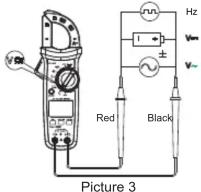
AC/DC Voltage and Voltage Frequency Measurement (Picture 3) 1) Insert the red test lead into the " V 'C + Ω → HZ' jack, black into the " COM " jack.
2) Turn the function switch to the AC/DC voltage position, and connect the test leads with the measured load or power supply in parallel.
Note:
- Do not input voltage above 600V. Although it is possible to measure higher voltage, it may damage the meter.
- Be cautious to avoid electric shock when measuring high voltage.
- When the measured voltage is 30V (AC) or 60V (DC), the LCD will display the high voltage alarm prompt "
3. Resistance Measurement (Picture 4)
1) Insert the red test lead into the " V 'C←Ω→Hz " jack, black into the " COM " jack.
2) Turn the function switch to the "Ω" position, press the SELECT button to select resistance measurement, and connect the test leads with both ends of the measured resistance in parallel.

Picture 4
Note:
- If the measured resistor is open or the resistance exceeds the maximum range, the LCD will display "OL".
- Before measuring the resistance online, switch of the power supply of the circuit, and fully discharge all capacitors to avoid inaccurate measurement.
- If the resistance is not less than 0.5Ω when the test leads are short-circuited, please check the test leads for looseness or other abnormalities.
- Do not input voltage higher than 30V to avoid personal injury.
4.Continuity Test (Picture 4)
1) Insert the red test lead into the "V°C+Ω→Hz" jack, black into the "·n" jack.
2) Turn the function switch to the “·” position, press the SELECT button to select continuity measurement, and connect the test leads with both ends of the measured load in parallel.
3) Measured resistance <10Ω : The circuit is in good conduction status; the buzzer beeps continuously. Measured resistance >31Ω : The buzzer makes no sound.
Note:
- Before measuring the continuity online, switch off the power supply of the circuit, and fully discharge all capacitors.
- Do not input voltage higher than 30V to avoid personal injury.
5. Diode Test (Picture 4)
1) Insert the red test lead into the "V C + Ω → Hz" jack, black into the "COM" jack. The polarity of the red test lead is "+" and that of the black test lead is "-".
2) Turn the function switch to the “→” position, press the SELECT button to select diode measurement, and connect the test leads with the positive and negative poles of the measured diode.
3) 0.08V ≤ reading <1.2V: The buzzer makes one beep indicating the normality of the diode. Reading <0.08V: The buzzer beeps continuously indicating the damage of the diode. For the silicon PN junction, the normal value is generally about 500\~800 mV.
Note:
- If the diode is open or its polarity is reversed, the LCD will display "OL".
- Before measuring the diode online, switch off the power supply of the circuit, and fully discharge all capacitors.
- Do not input voltage higher than 30V to avoid personal injury
6.Capacitance Measurement (UT202+/UT202A+, Picture 4)
1) Insert the red test lead into the "V°C+Ω→Hz" jack, black into the "COM" jack.
2) Turn the function switch to the “-” position, and connect the test leads with the measured capacitance in parallel. For capacitance 100nF, it is recommended to use “REL” measurement mode.
Note:
- If the measured capacitor is short-circuited or the capacitance exceeds the maximum range, the LCD will display "OL".
- When measuring capacitance >400µF , it may take some time to steady the readings.
- Before measuring, fully discharge all capacitors (especially for capacitors with high voltage) to avoid damage to the meter and user.
7. Temperature Measurement (UT202+ only, Picture 5)
1) Insert the positive pole of the temperature probe into the "V°C+Ω+Hz" jack and negative pole into the "COM"
2) Turn the function switch to the "°C/°F" position and the LCD will display room temperature.
3) Fix the temperature probe on the object to be tested, and read the temperature value of the tested object directly from the display after a few seconds.
4) Press the SELECT button to switch between °C and °F.
Note:
• The ambient temperature of the meter should be in the range of 18-28°C, otherwise it will cause measurement error.
• The positive and negative poles of the temperature probe should be properly connected. Do not measure non-insulated live
- objects to avoid incorrect readings.
- Do not input voltage higher than 30V to avoid personal injury.
8. Non-contact AG Electric Field Screening (NOV Picture 6)
- Non-contact AC Electric Field Sensing (NCV, Picture 6a) The electric field sensing sensitivity is divided into two levels ("EFHI" and "EFLo"). The meter defaults to "EFHI". Select different sensitivity levels for measurement according to the intensity of the measured electric field. When the electric field is around 220V (AC) 50Hz / 60Hz , select "EFHI"; when the electric field is around 110V (AC) 50Hz / 60Hz select "EFLO".
1) Turn the function switch to the NCV position.
2) Bring the NCV sensing end of the clamp jaws close to a charged electric field (socket, insulated wire, etc.). The LCD will display the segment "-", the buzzer will beep, and the red LED will flash. As the intensity of the measured electric field increases, the more the segments (----) are displayed, and the higher the frequency at which the buzzer beeps and the red LED flashes.

Picture 6a

Picture 6b
Note:
- Use the NCV sensing end of the clamp jaws to approach the measured electric field, otherwise the measurement sensitivity will be affected.
- When the measured electric field voltage is 100V (AC), observe whether the conductor of the measured electric field is insulated to avoid personal injury.
9. Live/Neutral Wire Measurement (UT202A+ only, Picture 6b)
1) Turn the function switch to the LIVE position
2) Insert the red test lead into the " V C + Ω → Hz " jack, make the suspended, and use the red test lead to touch the black test lead wire to distinguish the live or neutral wire socket, or bare.
3) When the neutral wire or uncharged object is detected, the "----" state is displayed.
4) When the AC "live wire" (>60 V) is detected, the LCD will display "LIVE" accompanied by audio/visual indication.
Note
- When using the LIVE function, in order to avoid the effect of the interference electric field of the COM input on the accuracy of distinguishing the live/neutral wire, please move the black test lead away from the COM input.
- When using the LIVE function, keep your hand away from the meter casing.
- When the LIVE function is applied to the measurement of dense high-voltage electric field, the accuracy of the meter to judge the "live wire" may be unstable. In this case, it should be judged by the LCD display and sound frequency together.
10. Others
1) Auto power off: During measurement, if there is no operation of the function switch or any button for 15 minutes, the meter will automatically shut down to save power. You can wake it up by pressing any button or restart it after turning the function switch to the OFF position. To disable the auto power off function, press and hold the SELECT button in the off state, and then turn on the meter. To resume the auto power off function, restart the meter after shutdown.
2) Buzzer: When any button is pressed or the function switch is turned, if it is valid, the buzzer will make one beep (about 0.25s). When measuring voltage or current, the buzzer will beep intermittently to indicate the over range.
3) Low battery detection: The battery voltage will be automatically detected as long as the meter is on. If it is lower than 2.5V, the LCD will display the "☐" symbol.
4) Low battery shutdown function: When the battery voltage is lower than 2.4V, the LCD displays the "symbol, the "Lo.bt" interface appears and lasts for about 10s, the buzzer makes consecutive beeps three times, and then the meter automatically shuts down (no interface is displayed).
X. Technical Specifications
Accuracy: ± (a% of reading + b digits), 1 year calibration period Ambient temperature and humidity: 23°C±5°C; ≤80%RH
Temperature coefficient: To ensure measurement accuracy, operating
1.AC Current
| Range | Resolution | Accuracy | Overload Protection | ||
| UT201+ UT202+ | UT202A+ | UT201+ UT202+ | UT202A+ | ||
| 4.000A | 6.000A | 0.001A | ±(4%+10) | 420A | 620A |
| 40.00A | 60.00A | 0.01A | ±(2%+10) | ||
| 400.0A | 600.0A | 0.1A | |||
| Current frequency monitoring: 50Hz~100Hz | 0.1Hz | ±(1.0%+5) | |||
• Frequency response: 50Hz\~100Hz
- For 4A range, open circuit allows least significant digit <3.
• Accuracy guarantee range: 1%\~100% of range
• The input current amplitude of the current frequency should be >2A.
2.AC Voltage
| Range | Resolution | Accuracy | Overload Protection | |
| UT201+ UT202+ | UT202A+ | |||
| 4.000V | 6.000V | 0.001V | ± (1.0%+5) | 600Vrms |
| 40.00V | 60.00V | 0.01V | ± (0.8%+5) | |
| 400.0V | 600.0V | 0.1V | ||
| 600V | 1V | |||
| Voltage frequency monitoring: 10Hz~10kHz | 0.01Hz~0.01kHz | ± (1.0%+5) | ||
- Input impedance: About 10MΩ
• Frequency response: 45Hz\~400Hz, true RMS display - Accuracy guarantee range: 1%\~100% of range; the input voltage amplitude of the voltage frequency should be >5V.
- The AC crest factor of a non-sinusoidal wave can reach 3.0 at 4000 counts while can only reach 1.8 at 6000 counts. The additional error should be added for the corresponding crest factor as follows:
a) Add 3% when crest factor is 1\~2
b) Add 5% when crest factor is 2\~2.5
c) Add 7% when crest factor is 2.5\~3
3.DC Voltage
| Range | Resolution | Accuracy | Overload Protection | |
| UT201+ UT202+ | UT202A+ | |||
| 400.0mV | 600.0mV | 0.1mV | ± (0.7%+3) | 600Vrms |
| 4.000V | 6.000V | 0.001V | ± (0.5%+2) | |
| 40.00V | 60.00V | 0.01V | ± (0.7%+3) | |
| 400.0V | 600.0V | 0.1V | ||
| 600V | 1V | |||
- Input impedance: About 10MΩ
- For mV range, short circuit allows least significant digit ₽.
• Accuracy guarantee range: 1%\~100% of range
4.Frequency/Duty Ratio (UT202A+ only)
| Range | Resolution | Accuracy | Overload Protection |
| 10Hz~10MHz | 0.01Hz~0.01MHz | ± (0.1%+4) | 600Vrms |
| 0.1%-99.9% | 0.1% | ± (3.0 + 5)% | 1) Measuring sensitivity: ≤ 100kHz : 200mVrms ≤ input amplitude ≤ 30Vrms >100kHz~1MHz: 600mVrms ≤ input amplitude ≤ 30Vrms >1MHz~10MHz: 1Vrms ≤ input amplitude ≤ 30Vrms 2) Duty ratio is only applicable to the measurement of square wave ≤ 10kHz ; amplitude: 1Vp-pFrequency ≤ 1kHz Duty ratio: 10.0%-95.0%Frequency >1kHz Duty ratio: 30.0%-70.0% |
- Resistance
| Range | Resolution | Accuracy | Overload Protection | |
| UT201+ UT202+ | UT202A+ | |||
| 400.0Ω | 600.0Ω | 0.1Ω | ±(1.0%+2) | 600Vrms |
| 4.000kΩ | 6.000kΩ | 0.001kΩ | ±(0.8%+2) | |
| 40.00kΩ | 60.00kΩ | 0.01kΩ | ||
| 400.0kΩ | 600.0kΩ | 0.1kΩ | ||
| 4.000MΩ | 6.000 MΩ | 0.001MΩ | ±(2.0%+5) | |
| 40.00MΩ | 60.00 MΩ | 0.01MΩ | ||
- Continuity
| Range | Resolution | Accuracy | Overload Protection | |
| UT201+ UT202+ | UT202A+ | |||
| 400.0Ω 6 | 00.0Ω 0.1Ω | <10Ω: Consecutive beeps>31Ω: No beep | 600Vrms | |
| Open circuit voltage: About 2.0V | ||||
- Diode
| Range | Resolution | Accuracy | Overload Protection | |
| UT201+UT202+ | UT202A+ | |||
| 4.000V | 6.000V | 0.001V | Open circuit voltage: About 2.2V (UT201+/UT202+)/3.9V (UT202A+)Measurable PN junction: Forward voltage drop ≤2V.For the silicon PN junction, the normal value is generally about 0.5~0.8V. | 600Vrms |
temperature should be within 18° C \~ 28° C and the fluctuation range should be within ±1° C. When the temperature is <18° C or >28° C, add temperature coefficient error 0.1 x (specified accuracy)/ ° C.
8.Capacitance
| Range | Resolution | Accuracy | Overload Protection | |
| UT202+ U 202A+ | ||||
| 4.000nF | 6.000nF | 0.001nF | ±(4.0%+10) | 600Vrms |
| 40.00nF | 60.00nF | 0.01nF | ||
| 400.0nF | 600.0nF | 0.1nF | ||
| 4.000uF | 6.000uF | 0.001uF | ±(4.0%+5) | |
| 40.00uF | 60.00uF | 0.01uF | ||
| 400.0uF | 600.0uF | 0.1uF | ||
| 4.000mF | 6.000mF | 0.001mF | ±10% | |
| 60.00mF | 0.01mF | |||
- Measured value = displayed value - open circuit value of the test leads (For capacitance ≤ 100nF , it is recommended to use "REL" measurement mode.)
- For capacitance range, open circuit allows least significant digit 20.
9.Temperature(UT202+ only)
| Range | Resolution | Accuracy | Overload Protection |
| -40°C~40°C | 1°C | ±4°C | 600Vrms |
| 40°C~500°C | ±(1.5%+5) | ||
| 500°C~1000°C | ±(2.0%+5) | ||
| -40°F~104°F | 1°F | ±6°F | |
| 104°F~932°F | ±(2.0%+6) | ||
| 932°F~1832°F | ±(2.5%+4) |
10 NCV.
| Range | Electric field sensing sensitivity level | Accuracy |
| NCV | EFLo | To sense the wire above 24±6V and identify whether the mains socket is charged |
| EFHI | To sense the wire above 74V±12V, to identify whether the mains socket is charged, or to judge the live/neutral wire of the socket according to the intensity of the sensing |
- Test results may be affected by different socket designs or wire insulation thickness.
XI. Maintenance
Warning: Before opening the rear cover of the meter, remove the test leads to avoid electric shock.
1.General Maintenance
1) When the meter is not in use, place the function switch in the OFF position to avoid continuous consumption of battery energy.
2) Clean the meter casing with a soft cloth and mild detergent. Do not use abrasives or solvents!
3) The maintenance and service must be implemented by qualified professionals or designated departments.
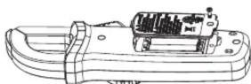
2.Battery Replacement (Picture 7)
1) Turn off the meter and remove the test leads from the input terminals
2) Unscrew the screw of the battery compartment, remove the battery cover, and replace the 2 standard AAA batteries according to the polarity indication.
3) Secure the battery cover and tighten the screw.
Picture 7
UNI-T
UNI-TREND TECHNOLOGY (CHINA) CO., LTD.
No. 6, Gong Ye Bei 1st Road,
Songshan Lake National High-Tech Industrial
Development Zone, Dongguan City,
Guangdong Province, China
Tel: (86-769) 6572 3888
www.uni-trend.com
- UT201+/UT202+/UT202A+ AC CLAMP METER USER MANUAL
- PREFACE
- LIMITED WARRANTY AND LIABILITY
- OVERVIEW
- FEATURES
- ACCESSORIES
- SAFETY INSTRUCTIONS
- GENERAL SPECIFICATIONS
- EXTERNAL STRUCTURE (PICTURE 1)
- BUTTON DESCRIPTION
- 2.HOLD/BACKLIGHT BUTTON
- 3.MAX/MIN BUTTON
- 4.REL BUTTON (UT202+/UT202A+)
- OPERATING INSTRUCTIONS
- NOTE
- RESISTANCE MEASUREMENT (PICTURE 4)
- 4.CONTINUITY TEST (PICTURE 4)
- DIODE TEST (PICTURE 4)
- 6.CAPACITANCE MEASUREMENT (UT202+/UT202A+, PICTURE 4)
- TEMPERATURE MEASUREMENT (UT202+ ONLY, PICTURE 5)
- NON-CONTACT AG ELECTRIC FIELD SCREENING (NOV PICTURE 6)
- LIVE/NEUTRAL WIRE MEASUREMENT (UT202A+ ONLY, PICTURE 6B)
- OTHERS
- TECHNICAL SPECIFICATIONS
- MAINTENANCE
- 2.BATTERY REPLACEMENT (PICTURE 7)
- UNI-T
Marque : Uni-T
Modèle : UT202A+
Catégorie : Multimètre