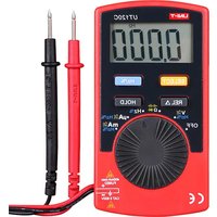
UT120C - Multimètre Uni-T - Notice d'utilisation et mode d'emploi gratuit
Retrouvez gratuitement la notice de l'appareil UT120C Uni-T au format PDF.


| Type de produit | Multimètre numérique |
| Marque | Uni-T |
| Modèle | UT120C |
| Dimensions | 115 x 60 x 25 mm |
| Poids | Environ 100 g |
| Alimentation | Pile 9 V (type 6F22) |
| Affichage | LCD 2000 points |
| Tension AC | 200 mV à 600 V |
| Tension DC | 200 mV à 600 V |
| Courant DC | 200 µA à 200 mA |
| Résistance | 200 Ω à 20 MΩ |
| Test de diode | Oui |
| Test de continuité | Oui (sonore) |
| Sécurité | CAT II 600 V |
| Entretien et nettoyage | Nettoyer avec un chiffon doux et sec. Ne pas utiliser de solvants. |
| Pièces détachées | Pile 9 V, fusible de rechange (si applicable) |
| Réparabilité | Confier à un technicien qualifié pour toute réparation. |
| Accessoires fournis | Pile, cordons de mesure, manuel d'utilisation |
| Garantie | 1 an |
FOIRE AUX QUESTIONS - UT120C Uni-T
Questions des utilisateurs sur UT120C Uni-T
0 question sur cet appareil. Repondez a celles que vous connaissez ou posez la votre.
Poser une nouvelle question sur cet appareil
Téléchargez la notice de votre Multimètre au format PDF gratuitement ! Retrouvez votre notice UT120C - Uni-T et reprennez votre appareil électronique en main. Sur cette page sont publiés tous les documents nécessaires à l'utilisation de votre appareil UT120C de la marque Uni-T.
MODE D'EMPLOI UT120C Uni-T
UNI-T®
UT120A/B
Operating Manual

Pocket Size Type Digital Multimeters
I. Introduction
UT120A/B is a 4000-count notebook type auto-ranging digital multimeter with following advantages complete functions, stable performance, high accuracy, low power consumption, novel structure, high degree of safety and reliability. It is capable of measuring AC/DC voltage, frequency, duty cycle, resistance, capacitance, diode and continuity, and becomes an ideal choice for measurement.
The Manual specifies safety information and notes relating to the meter, please read the manual carefully before use and strictly follow all warnings and notes during the operation.
⚠ Warning: Please read "Safety Information" before operating the meter.
II. Safety Information
UT120A/B digital meter is designed and manufactured in accordance with safety standard IEC61010, Double Insulation and Overvoltage CATII 600V as well as Pollution Degree 2.
Pay attention to warning symbol △ and its corresponding contents. Warning items state situations or actions that may cause potential risks to users or damage to the meter or measured equipments.
Operate the meter as specified in the manual; otherwise the protection offered by the meter will be impaired or lost.
-
Please ensure test pen's insulation layer is good and no insulation damage or broken wires before use. If test pen lead or meter housing is found with any obvious damage or failure to operate normally, do not use the meter
-
Keep your fingers behind the protection ring when using the test pen.
- To avoid electric shock or damage to the meter do not apply voltage above 600V between meter terminals and the grounding
- Be careful when working voltage is above DC60V and AC 42VRMS so as to prevent electric shock.
-
The meter is prohibited to use when back cover is not well placed, otherwise it may cause electric hazard
-
Do not exceed the specified limit value in order to avoid shock hazard or meter damage.
- In case of damage to meter, no gear changes of function switch are allowed during measurement.
- Do not change internal wiring without authorized permission which may endanger the meter or users.
- To ensure accurate readings, please change batteries timely if “💡” icon appears on LCD.
- Do not use the meter in environment with high temperature and humidity, especially the meter placed in humid places may be degraded after being moisture-affected.
- Clean the meter housing with soft wet cloth and mild detergent. No abrasive or dissolvent is allowed for cleaning.
International Electrical Symbols
| Low Battery Display | ± | Grounding | ⚠ Warning | |
| ~ | AC | → | DC | ■ Double Insulation |
| ● | Buzzer Continuity | → | Diode | +/- Capacitance |
| CE | Conformity with Europe Union standards | |||
III. Meter Description(See Figure 1)
1. LCD Display
- SELECT Button to toggle between Resistance, Capacitance, Diode and Continuity functions.(Capacitance for UT120B only).
- Relative Value Measurement (REL Button)
- Function Selection Switch Knob
- Hz/% Measurement (DCV, ACV
and Hz/% functions) - Data Hold (Hold Button);
- Positive Input End (Red Test Pen);
- Negative Input End (Black Test Pen);
IV.Button Functional Description
1. SELECT Button
It is used for switchover among resistance, capacitance, and buzzer continuity and diode measurements, indicated by beeping during the operation.
Pressing this button can wake up the meter from standby mode, which, however, will the auto power off function.
- REL Button (Relative Value Measurement)
With this button pressed down, current reading is set as reference value which will be subtracted from subsequent measurement readings. Press again to exit this mode and return to normal measuring status. This function is not available under frequency and duty cycle measurement.
3. Data Hold (HOLD Button):
Press this button to lock displayed values and hold the value; press it again to unlock this status and return to normal measuring mode.
4. Hz/% Measurement:
Switch to Hz or % measurement by pressing the button if under DCV and ACV ranges (the Hz/% key also used for frequency and duty cycle selection); where Hz/% measurement is finished, the meter will return to DCV or ACV status with the range default at 400mV(DCV) or 4V(ACV) and meanwhile® AUTO™ icon on LCD disappears. If high voltage is under test at the moment set functional knob switch or turn the meter off to reset auto-ranging for V before starting the test.
Under Hz/% mode, press the button to switch between Hz and % measurement.
V. Making Measurements
Switch on the meter to check if on the LCD there is 📋 icon which indicates the power supply falls low. To ensure high accuracy for measurement, please replace batteries. You should also take notice of notes beside the △, which indicate not to exceed the indicated value when testing voltage.
1. Measuring DC Voltage (See Figure 2)
(1) Set knob to DCV, AUTO and DC icon appear on LCD;
(2) Connect the black test pen to the cathode of the power being measured and the red test pen to the anode of the power being measured;
(3) Read measuring results displayed on LCD;
(4) Reverse test pens, then LCD will display negative readings.

Figure 2

Figure 3
2. Measuring AC Voltage(See Figure 3)
(1) Set knob to ACV, AUTO and AC icon appear on LCD;
(2) Connect the black test pen to the cathode of the power being measured and the red test pen to the anode of the power being measured;
(3) Read measuring values indicated on LCD;
(4) LCD will indicate negative readings if reversing test pen connection,
⚠️ Warnings:
- Do not input voltage above 600V, you may get desired values, however, which causes hazard to internal wiring.
● To avoid electric shock, please use it with extreme caution when
measuring high voltages.
- Disconnect test pens with measured circuits after finished all operations.
3. Measuring Resistance(See Figure 4)
(1) Set knob to Ω 等物 position
(2) Connect test pens to the resistance being measured; (3) Read measured results on the display.
(3) Read measured results on the display.
Notes:
- Please ensure to power off and discharge all capacitor before measuring online resistance so as to avoid meter damage.
- As for resistance measurement under 400Ω gear, test pen leads will cause error 0.1Ω 0.3Ω to readings In order to get accurate readings the ultimate results should subtract the short circuit reading values of the red and black test pens. It is suggested performing the operation under relative value measurement mode.
(No text)

Figure 4
P/N: 110401105302X MAY.2018 REV. 1
UNI-T®
- The meter should display "OL" if no signal is input, for instance, open circuit.
- For measurement 1MΩ , it normally takes several seconds to get stable readings.
4. Measuring Frequency and Duty Cycle(See Figure 5)
(1) Set knob switch to Hz/% or DCV or ACV position;
(2) Press Hz/% button to access frequency measurement;
(3) Connect test pens to frequency signal
source being m asured;
(4) Read results on LCD;
(5) Press Hz/% button again to
access % measurement
Note:
- The measured resolution based on frequency and waveform will vary slightly and have been preset with reference to sine wave.
5. Testing Diodes and Continuity(See Dotted Part in Figure 6)
(1) Set knob switch to Ω ✦•|| position:
(2) Press SELECT button to access diode mode
(press it again for continuity testing):
(3) Connect test pen leads to measured diode (with black test pen to cathode and red test pen to anode), then LCD reading will be a approximate value of diode forward voltage drop (when connecting test pens to both ends of the circuit being measured, if resistance between these two ends is 60Ω , the built-in buzzer will beep and the resistance value appears on LCD).


Figure 6
Notes:
- If measured diode is under open circuit status or with polarity reversed (namely, with black test pen connecting to anode and red test pen to cathode), LCD will display "OL".
- This function can be used to measure the voltage drop of PN joint of diode or semiconductor. For a normal silicon semiconductor, the reading of forward voltage drop should be within 0.5\~0.8V.
- To prevent meter damage, power off all circuits and discharge all capacitors completely before measuring online diode
- In order to prevent meter damage or personal injury, do not input voltages above DC60V or AC 30VRMS.
6. Measuring Capacitance(See Figure 7)
(1) Set knob switch to +k position
(2) As there is a capacitance reading displayed under open-circuit status, please select relative value measurement mode:
(3) Press REL button one time:
(4) Connect test pens to the capacitance being measured, then read the data on LCD.
Notes:
- Discharge all capacitors completely before testing.
- As for in-line capacitance measurement, it is required to power off all measured circuits and discharge completely all capacitors. If the capacitance being measured has polarity, ensure that the red pen is connected to the

anode of capacitance and black one to the cathode of capacitance.
- It normally takes several seconds to display the testing value when measuring more than capacitance over10uF.
- To avoid meter damage or personal injury, do not apply voltages above DC60V or AC 30VRMS.
VI. Technical Specifications
A. General Specifications
-
Max. Voltage between the Voltage Input Terminal and Grounding: 600VRMS or 600DCV
-
Range Selection: Auto
- Measuring Velocity: 3 times per second
- Max. Display: 3999
- Over Range Display: "OI"
- Polar Indication: “-” icon for negative input
- Low Battery Display: " ” on LCD
- Low Battery Display. ☑ on LCD
- Internal Battery: one Lithium manganese button cell, 2V, model: CP2032
- Internal Battery: one Lithium-manganese button cell, 3V, model: CR2032
- Operating Temperature: 0 C\~40 C (32 F\~104 F); Humidity: 675%
Humidity≤75%
Storage Temperature: -10°C\~50°C (14°F\~122°F)
Operating Altitude Height: ≤2000m
-
Dimensions: 109.8mm x 8.2mm x10.8mm
-
Weight: about 76 g (test pens and battery included)
12 Auto Power Off
The meter enters the standby mode after 30 minutes of inactivity of rotary switch and buttons. It can automatically power on (i.e. enter the working mode) if sliding rotary switch or any pressing button on the front panel. This function will be canceled if pressing SELECT button to wake up the meter "button to wake up the meter".
B. Accuracy Specifications
Accuracy:
Ambient T ± (a% readings+ b digits), calibration per year.
Relative H emperature: 23°C + 5°C:
umidity:≤75%
| Functions | Range | Resolution | Accuracy ± (a% readings+ b digits) | InputProtection | Description |
| DCVoltage | 4V | 1mV | ± (0.8%+1) | 600V DC600 V AC | Input Impedance 10M Ω; |
| 40V | 10mV | ||||
| 400V | 100mV | ||||
| 600V | 1V | ± (1%+3) | |||
| AC Voltage | 4V | 1mV | ± (1.2%+3) | 600V DC600 V AC | Input Impedance 10M Ω; FrequencyResponse: 40~400HzDisplay: RMS of Sinewave(Mean ValueResponse) |
| 40V | 10mV | ||||
| 400V | 100mV | ||||
| 600V | 1V | ± (1.5%+5) | |||
| Resistance | 400 Ω | 0.1 Ω | ± (1.2%+2) | 600 V AC | Open circuitvoltage is about0.45V. |
| 4K Ω | 1 Ω | ± (1%+2) | |||
| 40K Ω | 10 Ω | ||||
| 400K Ω | 100 Ω | ||||
| 4M Ω | 1K Ω | ± (1.2%+2) | |||
| 40M Ω | 10K Ω | ± (1.5%+2) |
| Functions | Range | Resolution | Accuracy ± (a% readings + b digits) | Input Protection | Description |
| Capacitance | 4.000nF | 0.001nF | 600 V AC | For reference | |
| 40.00nF | 0.01nF | ± (4%+3) | Measured under relative measurement, 0.45V for open circuit | ||
| 400.0nF | 0.1nF | ||||
| 4.000 μF | 0.001 μF | ||||
| 40.00 μF | 0.01 μF | ||||
| 100 μF | 0.1 μF | ± (5%+10) | Just for reading reference when measured capacitance above “100 μF”. | ||
| Frequency | 99.9Hz | 0.1Hz | ± (0.5%+3) | 600 V AC | Input sine wave 10Hz~10kHz: ≥1V RMS10kHz~100kHz: ≥30VRMS |
| 0.999kHz | 0.001kHz | ||||
| 9.99kHz | 0.01kHz | ||||
| 99.9kHz | 0.1kHz | ||||
| Duty Cycle | 0.1%~99.9% | 0.10% | 600 V AC | Use DUTY knob switch to shift to DUTY measurement mode when under AC/DC function (reading for reference only) | |
| Diode | → | 1mV | 0.5V~0.8v | 600V AC | 1.5 V for open circuit status |
| Buzzer Continuity | ●●● | 0.1Ω | About 60 Ω | 600V AC | Continuity Resistance 60 Ω : buzzer beeps; >0 Ω : not necessarily to beep, resistance approximate value is displayed, unit is Ω |
| Low Voltage Indication | About <2.4V | icon appears |
VII. Battery Replacement (See Figure 8)
If 📄 icon appears on LCD, please replace battery as follows:
-
Disconnect test pens with circuits being
measured, set knob switch to OFF position
then power off the meter. -
Unscrew the back housing and remove
the rear housing.
- Replace the battery with a new 3V battery.

conforms to UL STD 61010-1, 61010-2-030, 61010-031,
Intertek 4007682 certified to CSA STD C22.2 NO.61010-1, 61010-2-030, 61010-031

Figure 8
UNI-T
UNI-TREND TECHNOLOGY (CHINA) CO., LTD.
No6, Gong Ye Bei 1st Road,
Songshan Lake National High-Tech Industrial
Development Zone, Dongguan City.
Guangdong Province, Chin
Tel: (86-769) 8572 3888
http://www.uni-trend.com
- UNI-T®
- UT120A/B
- OPERATING MANUAL
- INTRODUCTION
- SAFETY INFORMATION
- METER DESCRIPTION(SEE FIGURE 1)
- LCD DISPLAY
- IV.BUTTON FUNCTIONAL DESCRIPTION
- SELECT BUTTON
- DATA HOLD (HOLD BUTTON)
- HZ/% MEASUREMENT
- MAKING MEASUREMENTS
- MEASURING DC VOLTAGE (SEE FIGURE 2)
- MEASURING AC VOLTAGE(SEE FIGURE 3)
- MEASURING RESISTANCE(SEE FIGURE 4)
- NOTES
- P/N: 110401105302X MAY.2018 REV. 1
- MEASURING FREQUENCY AND DUTY CYCLE(SEE FIGURE 5)
- TESTING DIODES AND CONTINUITY(SEE DOTTED PART IN FIGURE 6)
- MEASURING CAPACITANCE(SEE FIGURE 7)
- TECHNICAL SPECIFICATIONS
- GENERAL SPECIFICATIONS
- ACCURACY SPECIFICATIONS
- BATTERY REPLACEMENT (SEE FIGURE 8)
- UNI-T
Marque : Uni-T
Modèle : UT120C
Catégorie : Multimètre