
N1900B - Perceuse MAKITA - Notice d'utilisation et mode d'emploi gratuit
Retrouvez gratuitement la notice de l'appareil N1900B MAKITA au format PDF.

| Type de produit | Rabot électrique |
| Marque | MAKITA |
| Modèle | N1900B |
| Largeur de rabotage | 82 mm |
| Profondeur de rabotage | 1 mm |
| Profondeur de feuillure | 9 mm |
| Vitesse à vide | 16 000 min⁻¹ |
| Longueur hors tout | 290 mm |
| Poids net | 2,5 kg |
| Alimentation | Monophasé courant alternatif |
| Tension | Identique à celle indiquée sur la plaque signalétique |
| Isolation | Double isolation |
| Fonctions principales | Rabotage, feuillurage, chanfreinage |
| Réglage de profondeur | Molette frontale |
| Type de lame | Lames standard ou mini lames (selon version) |
| Accessoires inclus | Guide de coupe (pour modèles 1900B et N1900B) |
| Accessoires optionnels | Ensemble buse, guide de rallonge, support d'affûtage |
| Entretien | Remplacement des balais de charbon, nettoyage des copeaux |
| Sécurité | Double isolation, bouton de verrouillage, bouton de désengagement |
| Réparabilité | Réparation par centre agréé Makita, pièces d'origine |
FOIRE AUX QUESTIONS - N1900B MAKITA
Questions des utilisateurs sur N1900B MAKITA
0 question sur cet appareil. Repondez a celles que vous connaissez ou posez la votre.
Poser une nouvelle question sur cet appareil
Téléchargez la notice de votre Perceuse au format PDF gratuitement ! Retrouvez votre notice N1900B - MAKITA et reprennez votre appareil électronique en main. Sur cette page sont publiés tous les documents nécessaires à l'utilisation de votre appareil N1900B de la marque MAKITA.
MODE D'EMPLOI N1900B MAKITA
Power Planer
1900B
N1900B
1902

natural_image
Line drawing of a mechanical power tool with a labeled brand mark (no text or symbols beyond the label)
SPECIFICATIONS
| Model | 1900B/N1900B/1902 |
| Planing width | 82 mm |
| Planing depth | 1 mm |
| Shiplapping depth | 9 mm |
| No load speed (min ^-1 ) | 16,000 |
| Overall length | 290 mm |
| Net weight | 2.5 kg |
- Due to our continuing program of research and development, the specifications herein are subject to change without notice.
- Note: Specifications may differ from country to country.
Power supply
The tool should be connected only to a power supply of the same voltage as indicated on the nameplate, and can only be operated on single-phase AC supply. They are double-insulated in accordance with European Standard and can, therefore, also be used from sockets without earth wire.
natural_image
Line drawing of hands assembling a mechanical component with bolts (no text or symbols)1
text_image
1 2 3 4 52
text_image
6 3 5 7 8 9 10 11 123
text_image
13 5 14 11 15 16 17 12 9 184
text_image
18 2 4 1 16 195
natural_image
Line drawing of a hand operating a mechanical tool with a base plate (no text or symbols)6
text_image
207

text_image
21 208
text_image
22 209
text_image
24 2310
natural_image
Pure geometric diagram with diagonal hatching and a dashed rectangle (no text or symbols)11
text_image
25 2612
text_image
27 2813
natural_image
Line drawing of a wooden plank with a metal hook attached (no text or symbols)14
natural_image
Simple geometric diagram showing a shaded rectangle with curved internal lines and a dashed line extending from its right edge (no text or symbols)15
text_image
29 3016
natural_image
Technical line drawing of a mechanical assembly with a hand operating a workpiece (no text or symbols present)17
natural_image
Technical line drawing of a mechanical component with labeled part '32' (no text or symbols beyond label)18
text_image
33 34 3519
natural_image
Line drawing of two hands holding a device with a label '36' on the device (no other text or symbols)20
text_image
37 38 39 40 4121
natural_image
Line drawing of a hand using a tool to cut or mark a component on a textured base (no text or symbols)22
text_image
4223
text_image
34 4324
text_image
44 4325
Symbols
The followings show the symbols used for the tool. Be sure that you understand their meaning before use.

DOUBLE INSULATION

Read instruction manual.
Explanation of general view
| 1 | Bolt | 17 | Inside flank of gauge plate | 32 | Nozzle assembly |
| 2 | Drum | 18 | Mini planer blade | 33 | Chip cover screw |
| 3 | Planer blade | 19 | Groove | 34 | Chip cover |
| 4 | Drum cover | 20 | Switch trigger | 35 | Fit pin on nozzle assembly into this hole. |
| 5 | Adjusting plate | 21 | Lock button | ||
| 6 | Blade edge | 22 | Lock-off button | 36 | Sharpening holder |
| 7 | Screws | 23 | Start | 37 | Wing nut |
| 8 | Heel | 24 | End | 38 | Blade (A) |
| 9 | Back side of gauge base | 25 | Blade edge | 39 | Blade (B) |
| 10 | Inside edge of gauge plate | 26 | Cutting line | 40 | Side (C) |
| 11 | Gauge plate | 27 | Screw | 41 | Side (D) |
| 12 | Gauge base | 28 | Edge fence | 42 | Limit mark |
| 13 | Pan head screw | 29 | “V” groove | 43 | Screwdriver |
| 14 | Planer blade locating lugs | 30 | Front base | 44 | Brush holder cap |
| 15 | Heel of adjusting plate | 31 | Align the “V” groove with the edge of the workpiece. | ||
| 16 | Set plate |
SAFETY INSTRUCTIONS
ENA001-2
WARNING! When using electric tools, basic safety precautions, including the following, should always be followed to reduce the risk of fire, electric shock and personal injury. Read all these instructions before operating this product and save these instructions.
For safe operations:
- Keep work area clean.
Cluttered areas and benches invite injuries.
- Consider work area environment.
Do not expose power tools to rain. Do not use power tools in damp or wet locations. Keep work area well lit. Do not use power tools where there is risk to cause fire or explosion.
- Guard against electric shock.
Avoid body contact with earthed or grounded surfaces(e.g. pipes, radiators, ranges, refrigerators).
- Keep children away.
Do not let visitors touch the tool or extension cord. All visitors should be kept away from work area.
- Store idle tools.
When not in use, tools should be stored in a dry, high or locked up place, out of reach of children.
- Do not force the tool.
It will do the job better and safer at the rate for which it was intended.
- Use the right tool.
Do not force small tools or attachments to do the job of a heavy duty tool. Do not use tools for purposes not intended; for example, do not use circular saws to cut tree limbs or logs.
- Dress properly.
Do not wear loose clothing or jewellery, they can be caught in moving parts. Rubber gloves and non-skid footwear are recommended when working outdoors. Wear protecting hair covering to contain long hair.
- Use safety glasses and hearing protection.
Also use face or dust mask if the cutting operation is dusty.
- Connect dust extraction equipment.
If devices are provided for the connection of dust extraction and collection facilities ensure these are connected and properly used.
- Do not abuse the cord.
Never carry the tool by the cord or yank it to disconnect it from the socket. Keep the cord away from heat, oil and sharp edges.
- Secure work.
Use clamps or a vice to hold the work. It is safer than using your hand and it frees both hands to operate the tool.
- Do not overreach.
Keep proper footing and balance at all times.
- Maintain tools with care.
Keep cutting tools sharp and clean for better and safer performance. Follow instructions for lubrication and changing accessories. Inspect tool cord periodically and if damaged have it repaired by an authorized service facility. Inspect extension cords periodically and replace, if damaged. Keep handles dry, clean and free from oil and grease.
- Disconnect tools.
When not in use, before servicing and when changing accessories such as blades, bits and cutters.
- Remove adjusting keys and wrenches.
Form the habit of checking to see that keys and adjusting wrenches are removed from the tool before turning it on.
- Avoid unintentional starting.
Do not carry a plugged-in tool with a finger on the switch. Ensure switch is off when plugging in.
- Use outdoor extension leads.
When tool is used outdoors, use only extension cords intended for outdoor use.
- Stay alert.
Watch what you are doing. Use common sense. Do not operate tool when you are tired.
20. Check damaged parts.
Before further use of the tool, a guard or other part that is damaged should be carefully checked to determine that it will operate properly and perform its intended function. Check for alignment of moving parts, free running of moving parts, breakage of parts, mounting and any other conditions that may affect its operation. A guard or other part that is damaged should be properly repaired or replaced by an authorized service center unless otherwise indicated in this instruction manual. Have defective switches replaced by an authorized service facility. Do not use the tool if the switch does not turn it on and off.
21. Warning.
The use of any accessory or attachment, other than those recommended in this instruction manual or the catalog, may present a risk of personal injury.
22. Have your tool repaired by a qualified person.
This electric tool is in accordance with the relevant safety requirements. Repairs should only be carried out by qualified persons using original spare parts, otherwise this may result in considerable danger to the user.
ADDITIONAL SAFETY RULES
ENB045-2
- Rags, cloth, cord, string and the like should never be left around the work area.
- Avoid cutting nails. Inspect for and remove all nails from the workpiece before operation.
- Use only sharp blades. Handle the blades very carefully.
- Be sure the blade installation bolts are securely tightened before operation.
- Hold the tool firmly.
- Keep hands away from rotating parts.
- Before using the tool on an actual workpiece, let it run for a while. Watch for vibration or wobbling that could indicate poor installation or a poorly balanced blade.
- Make sure the blade is not contacting the workpiece before the switch is turned on.
- Wait until the blade attains full speed before cutting.
- Keep at least 200 mm away from the tool at all times.
- Always switch off and wait for the blades to come to a complete stop before any adjusting.
- Never stick your finger into the chip chute. Chute may jam when cutting damp wood. Clean out chips with a stick.
- Do not leave the tool running. Operate the tool only when hand-held.
- When leaving the planer, switch off and set it with the front base up on a wooden block, so that the blades do not contact anything.
- Always change both blades or covers on the drum, otherwise the resulting imbalance will cause vibration and shorten tool life.
- Wait for complete run-down before putting the tool aside.
- Use only Makita blades specified in this manual.
SAVE THESE INSTRUCTIONS.
OPERATING INSTRUCTIONS
Removing or installing planer blades
CAUTION:
Always be sure that the tool is switched off and unplugged before removing or installing the blade.
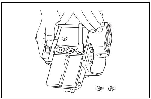
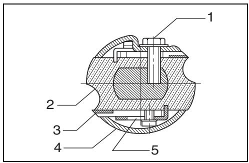
For tool with standard planer blades (Fig. 1, 2 & 3)
To remove the blades on the drum, unscrew the three installation bolts with the socket wrench. The drum cover comes off together with the blades.
To install the blades, first clean out all chips or foreign matter adhering to the drum or blades. Use blades of the same dimensions and weight, or drum oscillation/vibration will result, causing poor planing action and, eventually, tool breakdown.
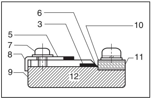
Place the blade on the gauge base so that the blade edge is perfectly flush with the inside edge of the gauge plate. Place the adjusting plate on the blade, then simply press in the heel of the adjusting plate flush with the back side of the gauge base and tighten two screws on the adjusting plate. Now slip the heel of the adjusting plate into the drum groove, then fit the drum cover on it. Tighten the three installation bolts evenly and alternately with the socket wrench.
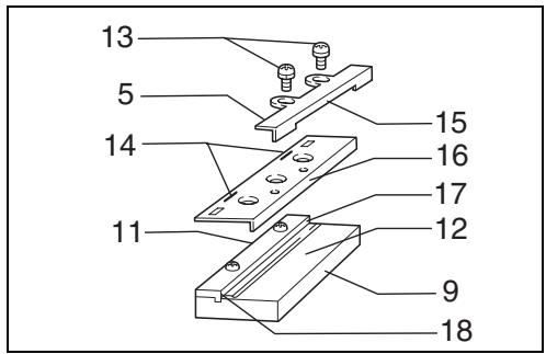
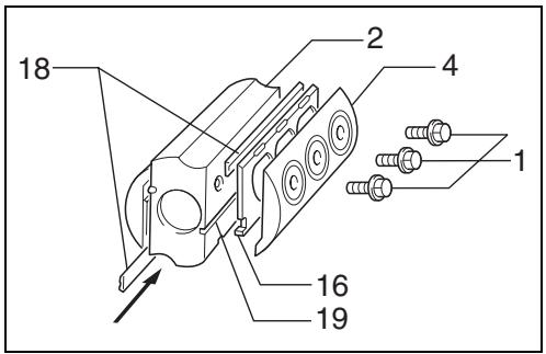
For tool with mini planer blades (Fig. 1, 4 & 5)
- Remove the existing blade, if the tool has been in use, carefully clean the drum surfaces and the drum cover. To remove the blades on the drum, unscrew the three installation bolts with the socket wrench. The drum cover comes off together with the blades.
- To install the blades, loosely attach the adjust plate to the set plate with the pan head screws and set the mini planer blade on the gauge base so that the cutting edge of the blade is perfectly flush with the inside flank of the gauge plate.
- Set the adjusting plate/set plate on the gauge base so that the planer blade locating lugs on the set plate rest in the mini planer blade groove, then press in the heel of the adjusting plate flush with the back side of the gauge base and tighten the pan head screws.
- It is important that the blade sits flush with the inside flank of the gauge plate, the planer blade locating lugs sit in the blade groove and the heel of the adjusting plate is flush with the back side of the gauge base. Check this alignment carefully to ensure uniform cutting.
- Slip the heel of the adjusting plate into the groove of the drum.
- Set the drum cover over the adjusting plate/set plate and screw in the three hex flange head bolts so that a gap exists between the drum and the set plate to slide the mini planer blade into position. The blade will be positioned by the planer blade locating lugs on the set plate.
- The blade's lengthwise adjustment will need to be manually positioned so that the blade ends are clear and equidistant from the housing on one side and the metal bracket on the other.
-
Tighten the three hex flange head bolts (with the socket wrench provided) and hand rotate the drum to check clearances between the blade ends and the tool body.
-
Check the three hex flange head bolts for final tightness.
- Repeat procedures 1 - 9 for other blade.
CAUTION:
Tighten the blade installation bolts carefully when attaching the blades to the tool. A loose installation bolt can be dangerous. Always check to see they are tightened securely.
For the correct planer blade setting
Your planing surface will end up rough and uneven, unless the blade is set properly and securely. The blade must be mounted so that the cutting edge is absolutely level, that is, parallel to the surface of the rear base.
Below are some examples of proper and improper settings.
(A) Front base (Movable shoe)
(B) Rear base (Stationary shoe)
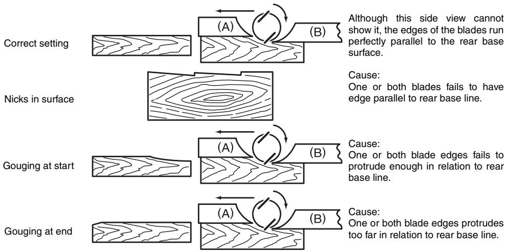
flowchart
graph TD
    A["Correct setting"] --> B["(A)"]
    B --> C["(B)"]
    C --> D["Although this side view cannot show it, the edges of the blades run perfectly parallel to the rear base surface."]
    E["Nicks in surface"] --> F["(A)"]
    F --> G["(B)"]
    G --> H["Cause: One or both blades fails to have edge parallel to rear base line."]
    I["Gouging at start"] --> J["(A)"]
    J --> K["(B)"]
    K --> L["Cause: One or both blade edges fails to protrude enough in relation to rear base line."]
    M["Gouging at end"] --> N["(A)"]
    N --> O["(B)"]
    O --> P["Cause: One or both blade edges protrudes too far in relation to rear base line."]
Adjusting the depth of cut (Fig. 6)
Depth of cut may be adjusted by simply turning the knob on the front of the tool.
Switch action
CAUTION:
Before plugging in the tool, always check to see that the switch trigger actuates properly and returns to the "OFF" position when released.
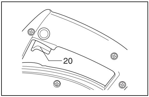
For tool without lock button and lock-off button (Fig. 7)
To start the tool, simply pull the switch trigger. Release the switch trigger to stop.
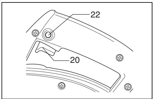
For tool with lock button (Fig. 8)
To start the tool, simply pull the switch trigger. Release the switch trigger to stop. For continuous operation, pull the switch trigger and then push in the lock button. To stop the tool from the locked position, pull the switch trigger fully, then release it.
For tool with lock-off button (Fig. 9)
To prevent the trigger from being accidentally pulled, a lock-off button is provided. To start the tool, press the lock-off button and pull the switch trigger. Release the switch trigger to stop.
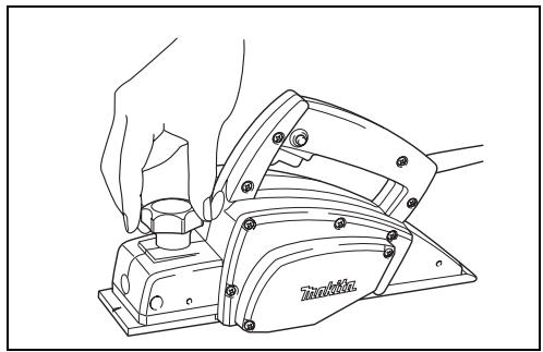
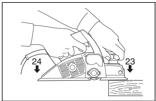
Planing operation (Fig. 10)
First, rest the tool front base flat upon the workpiece surface without the blades making any contact. Switch on and wait until the blades attain full speed. Then move the tool gently forward. Apply pressure on the front of tool at the start of planing, and at the back at the end of planing. Planing will be easier if you incline the workpiece in stationary fashion, so that you can plane somewhat downhill. The speed and depth of cut determine the kind of finish. The power planer keeps cutting at a speed that will not result in jamming by chips. For rough cutting, the depth of cut can be increased, while for a good finish you should reduce the depth of cut and advance the tool more slowly.
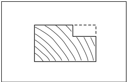
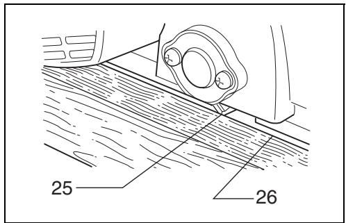
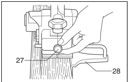
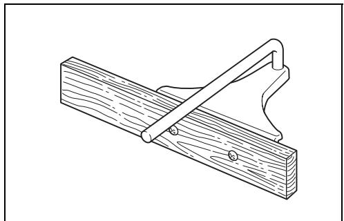
Shiplapping (Fig. 11, 12, 13 & 14)
To make a stepped cut as shown in Fig. 11, use the edge fence (Standard equipment for 1900B and N1900B; optional accessory for 1902).
Draw a cutting line on the workpiece. Insert the edge fence into the hole in the front of the tool. Align the blade edge with the cutting line.
Adjust the edge fence until it comes in contact with the side of the workpiece, then secure it by tightening the screw.
You may wish to add to the length of the fence by attaching an extra piece of wood. Convenient holes are provided in the fence for this purpose, and also for attaching an extension guide (optional accessory).
NOTE:
When planing, move the tool with the edge fence flush with the side of the workpiece. Otherwise uneven planing may result.
Max. shiplapping depth is 9 mm.
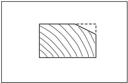
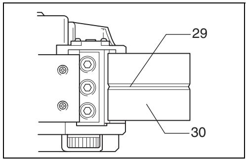
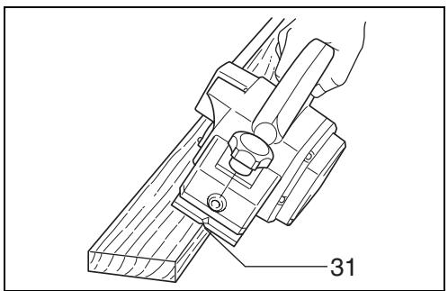
Chamfering (Fig. 15, 16 & 17)
To make a cut as shown in Fig. 15, align the "V" groove in the front base with the edge of the workpiece and plane it as shown in the Fig. 17.
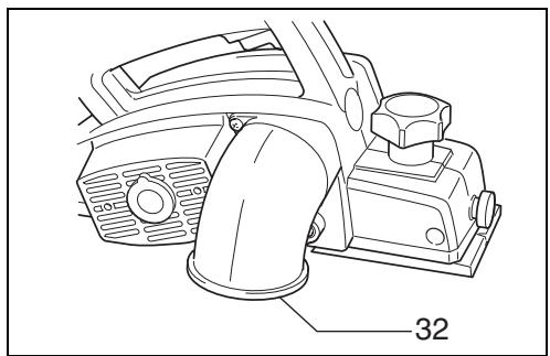
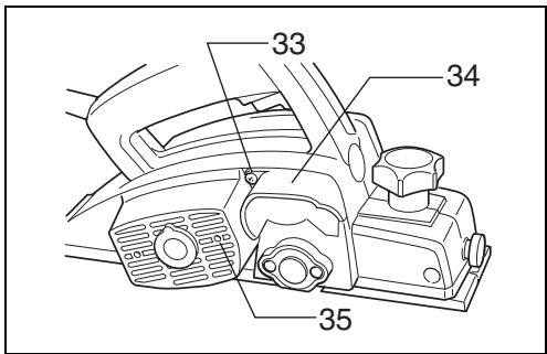
Nozzle assembly (optional accessory)
(Fig. 18 & 19)
Use of the special nozzle assembly will minimize chip scatter, making for a cleaner work area.
The nozzle assembly may be attached after the chip cover on the tool body is removed. When slipping on the assembly, fit the pin on it into the rear cover hole. Use the chip cover screws to fasten it in place.
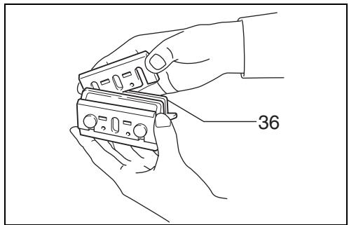
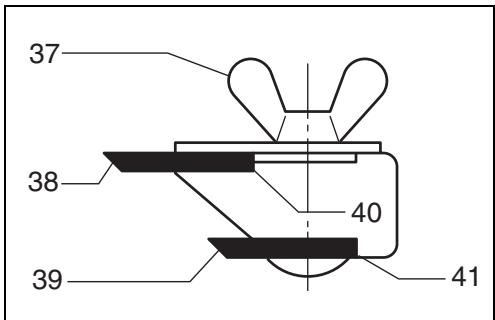
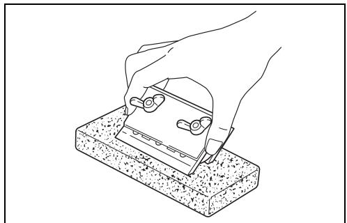
Sharpening the planer blades (Fig. 20, 21 & 22)
For standard blades only
Always keep your blades sharp for the best performance possible. Use the sharpening holder to remove nicks and produce a fine edge.
First, loosen the two wing nuts on the holder and insert the blades (A) and (B), so that they contact the sides (C) and (D). Then tighten the wing nuts.
Immerse the dressing stone in water for 2 or 3 minutes before sharpening. Hold the holder so that the blades both contact the dressing stone for simultaneous sharpening at the same angle.
MAINTENANCE
CAUTION:
Always be sure that the tool is switched off and unplugged before carrying out any work on the tool.
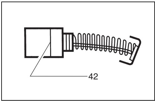
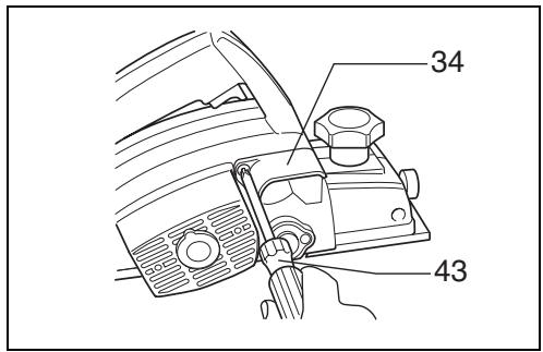
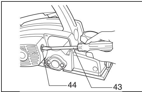
Replacing carbon brushes (Fig. 23, 24 & 25)
Remove and check the carbon brushes regularly. Replace when they wear down to the limit mark. Keep the carbon brushes clean and free to slip in the holders. Both carbon brushes should be replaced at the same time. Use only identical carbon brushes.
Use a screwdriver to remove the chip cover. Use a screwdriver to remove the brush holder caps. Take out the worn carbon brushes, insert the new ones and secure the brush holder caps.
To maintain product SAFETY and RELIABILITY, repairs, any other maintenance or adjustment should be performed by Makita Authorized or Factory Service Centres, always using Makita replacement parts.
Makita Corporation
Anjo, Aichi, Japan
Made in Japan
883185G5