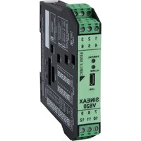
SINEAX V620 - Convertisseur audio/vidéo Camille Bauer - Notice d'utilisation et mode d'emploi gratuit
Retrouvez gratuitement la notice de l'appareil SINEAX V620 Camille Bauer au format PDF.


| Type de produit | Convertisseur audio/vidéo |
| Marque | Camille Bauer |
| Modèle | SINEAX V620 |
| Dimensions (L x l x h) | 150 x 80 x 40 mm |
| Poids | 0,5 kg |
| Alimentation | 24 V DC |
| Consommation électrique | 5 W |
| Fonctions principales | Conversion de signaux audio et vidéo analogiques, isolation galvanique |
| Entrées | Audio stéréo RCA, Vidéo composite |
| Sorties | Audio stéréo symétrique, Vidéo composite |
| Bande passante audio | 20 Hz – 20 kHz |
| Bande passante vidéo | 5 Hz – 10 MHz |
| Température de fonctionnement | -10°C à +50°C |
| Humidité relative | Jusqu'à 80% sans condensation |
| Indice de protection | IP20 |
| Matériau du boîtier | Aluminium |
| Entretien et nettoyage | Nettoyer avec un chiffon sec et non pelucheux |
| Sécurité | Utiliser dans un environnement sec, ne pas exposer à l'humidité |
| Pièces détachées et réparabilité | Contacter le service après-vente Camille Bauer |
| Informations générales | Conforme aux normes CE, garantie 2 ans |
FOIRE AUX QUESTIONS - SINEAX V620 Camille Bauer
Questions des utilisateurs sur SINEAX V620 Camille Bauer
0 question sur cet appareil. Repondez a celles que vous connaissez ou posez la votre.
Poser une nouvelle question sur cet appareil
Téléchargez la notice de votre Convertisseur audio/vidéo au format PDF gratuitement ! Retrouvez votre notice SINEAX V620 - Camille Bauer et reprennez votre appareil électronique en main. Sur cette page sont publiés tous les documents nécessaires à l'utilisation de votre appareil SINEAX V620 de la marque Camille Bauer.
MODE D'EMPLOI SINEAX V620 Camille Bauer
SINEAX V620
Universal-Signalkonverter
für mA, V, TC, RTD, Ω
CAMILLE BAUER
163 022 10.17
PM1000897 000 02
Allgemeine Eigenschaften
- Universal-Eingang, Spannung, Strom, Thermoelemente, Widerstandsthermometer, Potentiometer, Rheostat, veränderbarer Widerstand 2-Leiter
- Stromversorgung des Sensors in 2-Draht-Technik: 20 V DC stabilisiert, max. 20 mA, vor Kurzschluss geschützt.
- Messung und Rückübertragung auf galvanisch getrenntem Analogausgang mit aktivem/passivem Ausgang für Spannung und Strom.
- Auswahl mittels DIP-Schalter von: Eingangsart, START-END, Ausgangsmodus (Null ermittlung, Skalenumkehrung), Ausgangsart (mA oder V).
- Anzeige des Anliegens der Stromversorgung, Skalenüberschreitung oder Einrichtfehler bzw. Alarmstatus auf der Frontseite.
- Ausgang für Alarmkontakt mit Relais (Spst), mittels PC einrichtbar.
- STROBE-Eingang zur Aktivierung des Analogausgangs zur Steuerung einer SPS (alternativ zum Alarmkontakt).
- Möglichkeit zur Programmierung des Skalenanfangs- und endwertes, der zusätzlichen Eingangsarten, der Wurzelbildung, des Filters, des Burn-out usw. mittels PC.
• Galvanische 3-Wege-Trennung: 1500 V AC.
Technische Daten
| Spannungsversorgung | 10...40 V DC, 19...28 V AC, 50...60 Hz, max. 2.5 W, 1.6 W bei 24 V DC mit Ausgang 20 mA | |||
| Eingang Spannung | Zweipolg von 75 mV bis zu 20 V in 9 Skalen, Eingangs impedande 1 MΩ, max. Auflösung 15 Bt + Zeichen | |||
| Eingang Strom | Zweipolg bis zu 20 mA, Eingangsimpedanz 50 Ω, max. Auflösung 1 μA | |||
| Eingang Widerstandsthermometer (RTD)PT100, PFT500, PT1000,N100, KTY81, KTY84, NTC | Messung mit 3, 4 oder 4 Dränten, Aulüssostrom 0.56 mA, Ausstellung 0,0 °C, automatische Messung von Kabelunterbrechung oder RTD. Für NTR Widerstandswert < 25 kΩ, KTY81, KTY84 und NTC nur über Software einrichtbar | |||
| Eingang Thermoelument | Typ J, K, R, S, T, B, E, N; Auflösung 2,5 μV, automatische Messung der Unterbrechung TC, Eingangsimpedanz >5 MΩ | |||
| Eingang Regler Skalenendwert | min. 500 Ω, max. 25 kΩ | |||
| Eingang Potentiometer | Auslösespannung 300 MΩ, Eingangsimpedanz > 5 MΩ, Potentiometer wert von 500 Ω bis 100 kΩ (mit Hilfe eines parallel geschafften Widerstandes von 300 C) | |||
| Bemusterungsfrequenz | Variabel von 240 sps bei Auflösung 11 Bt + Zeichen bis 15 sps bei Auflösung 15 Bt + Zeichen (typische Werbe) | |||
| Reaktionszeit | 35 ms bei Auflösung 11 Bt, 140 ms bei Auflösung 16 Bt (Messung von Spannung, Strom, Potentiometer) | |||
| Ausgang | 1:0...20/4...20 mA, max. Lastwiderstand 600 Ω; V.0...5/0...10/1...5/2...10 V, min. Lastwiderstand 2 kΩ | |||
| Relais Ausgang (spdt) Schafft | 2.250 Ω, 1.25 mV | |||
| instellung: 1 ... 30 V DC / AC | ||||
| Umgebungsbedingungen | Temperatur: ... 20...60 °C, Feuchtigkeit min. 30%, max. 90% bei 40 °C ohne Kondensation (siehe Abschnitt +installationsvorschriften): | |||
| Fehler in Bezug auf den maximalen Messbereich | Kalibrierfehler | Temperatur-koeffizient | Linearitäts-fehler | Anderes |
| Eingang für Spannung/Strom | 0,3% | 0,05% EMI: < 1% | ||
| Eingang für PTC J, K, E, T, N | 0,5% 0,2 °C | 0,01% / °K | +(2) EMI: <1%d | |
| Eingang für PTC B (4) 0,5% | 1,5 °C | |||
| Ausgleich Kaltverbindung 2 °C Umgebungstemperatur 0 bis 50 °C | ||||
| Potentiometer/Widerstand | 0,3% | 0,1% | EMt: < 1% | |
| Eingang Heizwiderstand (5) | 0,3% | 0,01% / °K | t>0°C 0,02% t<0°C 0,05% | (1) EMI: < 1% |
| Spannungsausgang (3) | 0,3% 0,01% | |||
| Datenspeicher | EEPROM für alle Konfigurationsdaten; Speicherzeit 40 Jahre | |||
CE EN 61000-6-4/2007 (elektromagnetische Störungen, Industrielle Umgebung) EN 61000-6-2/2005 (elektromagnetische Unempfindlichkeit, industrielle Umgebung) EN 61010-1/2001 (Sicherheit)
Alle Schaltkreise müssen mit einer doppelten Isolierung gegenüber gefährliche Spannung führenden Schaltkreisen versehen werden. Der Transformator zur Stromversorgung muss dem Standard EN 60742: Isolier- und Sicherheitstransformatoren, Vorschriften entsprechen.
Anmerkungen:
– Benutzen mit Kupferleitung
– Benutzen in Verschmutzungsgrad 2 Umgebung
– Spannungsversorgung muss Klasse 2 sein
- Bei Verwendung eines galvanisch getrennten Netzteils sollte eine Sicherung von 2,5 A max. davor installiert werden.
(1) Einfluss des Kabelwiderstands 0,005%/Ω, max. 20 Ω
(2) Einfluss des Kabelwiderstands 0.1 μV/Ω
(3) Zu den Fehlern bezüglich des gewählten Eingangs zu summierende Werte
(4) Ausgang null für t < 400 °C
(5) Alle auf den Widerstandswert zu berechnenden Fehler
SINEAX V620 DEUTSCH 1/4 SINEAX V620 DEUTSCH 2/4 SINEAX V620 DEUTSCH 3/4
Auswahl des Eingangs
Die Auswahl der Eingangsart erfolgt durch Einrichtung der Gruppe von DIP-Schaltern SW1 seitlich des Moduls.
Jeder Eingangsart entspricht eine bestimmte Anzahl von Skalenanfangs- und endwerten, die mit der Gruppe SW2 wählbar sind.
In der nachstehenden Tabelle werden die möglichen Werte für START und END je nach der gewählten Eingangsart aufgeführt.
In der Tabelle gibt die linke Spalte die Kombination der DIP-Schalter an, die für die gewählten START und END einzurichten sind.
Anmerkung für alle Tabellen:
Die Beschriftung ● zeigt an, dass der DIP-Schalter in der ON-Position ist.
Kein Eintrag bedeutet, dass der DIP-Schalter in der OFF-Position ist!
SW1: EINGANGSARTEN
| Eingangsarten Eingangsarten | |||||||||
| 1 | 2 | 3 | 4 | 1 | 2 | 3 | 4 | ||
| V | ● | Tc K | |||||||
| ● | Ω/Regler | ● | ● | Tc R | |||||
| ● | mA | ● | ● | Tc S | |||||
| ● | ● | Ni100 | ● | ● | ● | Tc T | |||
| ● | PT100 | ● | ● | Tc B | |||||
| ● | ● | PT500 | ● | ● | ● | Tc E | |||
| ● | ● | PT1000 | ● | ● | ● | Tc N | |||
| ● | ● | ● | Tc J | ● | ● | ● | ● | Potentiometer | |
SW2: START/END
| END | |||||||
| 1 | 2 | 3 | 4 | 5 | 6 | ||
| 1 | 1 | ||||||
| ● | 2 | ● | 2 | ||||
| ● | 3 | ● | 3 | ||||
| ● | ● | 4 | ● | ● | 4 | ||
| ● | 5 | ● | 5 | ||||
| ● | ● | 6 | ● | ● | 6 | ||
| ● | ● | 7 | ● | ● | 7 | ||
| ● | ● | ● | 8 | ● | ● | ● | 8 |
SW2
| Spannung | Widerstand/Regler | Strom | Potentiometer | |||||||
| START | END | START | END | START | END | START | END | |||
| 1 | (*) | (*) | (*) | (*) | (*) | (*) | (*) | (*) | ||
| ● | 2 | 0 V | 100 mV | 0 Ω | 1 kΩ | 0 mA | 1 mA | 0% | 40% | |
| ● | 3 | 400 mV | 200 mV | 0,5 kΩ | 2 kΩ | 1 mA | 2 mA | 10% | 50% | |
| ● | 4 | 1 V | 500 mV | 1 kΩ | 3 kΩ | 4 mA | 3 mA | 20% | 60% | |
| ● | 2 V | 1 V | 2 kΩ | 5 kΩ | -1 mA | 4 mA | 30% | 70% | ||
| ● | 6 | -5 V | 5 V | 5 kΩ | 10 kΩ | -5 mA | 5 mA | 40% | 80% | |
| ● | 7 | -10 V | 10 V | 10 kΩ | 15 kΩ | -10 mA | 10 mA | 50% | 90% | |
| ● | ● | -8 V | 20 V | 15 kΩ | 25 kΩ | -20 mA | 20 mA | 60% | 100% | |
| Ni100 (RTD) PT100 (RD) PT50 (RD) PT100 (RD) | |||||||||
| START | END | START | END | START | END | START | END | ||
| 1 | (°) | (°) | (°) | (°) | (°) | (°) | (°) | (°) | |
| ● | 2 | -50 °C | 20 °C | -200 °C | 50 °C | -200 °C | 0 °C | -200 °C | 0 °C |
| ● | 3 | -30 °C | 40 °C | -100 °C | 100 °C | -100 °C | 50 °C | -100 °C | 50 °C |
| ● | 4 | -20 °C | 50 °C | -50 °C | 200 °C | -50 °C | 100 °C | -50 °C | 100 °C |
| ● | 5 | 0 °C | 80 °C | 0 °C | 300 °C | 0 °C | 150 °C | 0 °C | 150 °C |
| ● | 6 | 20 °C | 100 °C | 50 °C | 400 °C | 50 °C | 200 °C | 50 °C | 200 °C |
| ● | 7 | 30 °C | 150 °C | 100 °C | 500 °C | 100 °C | 300 °C | 100 °C | 300 °C |
| ● | 8 | 50 °C | 200 °C | 200 °C | 600 °C | 150 °C | 400 °C | 200 °C | 400 °C |
| Thermoelement J | Thermoelement K | Thermoelement R | Thermoelement S | ||||||||||
| START | END | START | END | START | END | START | END | ||||||
| 1 | (*) | (*) | (*) | (*) | (*) | (*) | (*) | (*) | (*) | (*) | (*) | ||
| ● | 2 | -200 °C | 100 °C | -200 °C | 200 °C | 0 °C | 400 °C | 0 °C | 400 °C | 0 °C | 400 °C | 0 °C | |
| ● | 3 | -100 °C | 200 °C | -100 °C | 400 °C | 100 °C | 600 °C | 100 °C | 600 °C | 100 °C | 600 °C | 100 °C | |
| ● | 4 | 0 °C | 300 °C | 0 °C | 600 °C | 200 °C | 800 °C | 200 °C | 800 °C | 200 °C | 800 °C | 800 °C | |
| ● | 5 | 100 °C | 400 °C | 100 °C | 800 °C | 300 °C | 1000 °C | 300 °C | 1000 °C | 300 °C | 1000 °C | 1000 °C | |
| ● | ● | 6 | -200 °C | 0.50 °C | 200 °C | 1000 °C | 400 °C | 1200 °C | 400 °C | 1200 °C | 400 °C | 1200 °C | 1200 °C |
| ● | ● | 7 | 300 °C | 800 °C | 300 °C | 1200 °C | 600 °C | 1400 °C | 600 °C | 1400 °C | 600 °C | 1400 °C | 1400 °C |
| ● | ● | 8 | 500 °C | 1000 °C | 500 °C | 1300 °C | 800 °C | 1750 °C | 800 °C | 1750 °C | 800 °C | 1750 °C | 1750 °C |
| Thermoelement T | Thermoelement B | Thermoelement E | Thermoelement N | ||||||
| START | END | START | END | START | END | START | END | ||
| 1 | (°) | (°) | (°) | (°) | (°) | (°) | (°) | (°) | |
| ● | 2 - 200 °C | 50 °C | 0 °C | 500 °C | -200 °C | 50 °C | -200 °C | 200 °C | |
| ● | 3 - 100 °C | 100 °C | 500 °C | 600 °C | -100 °C | 100 °C | -100 °C | 400 °C | |
| ● | 4 - 50 °C | 150 °C | 600 °C | 800 °C | 0 °C | 200 °C | 0 °C | 600 °C | |
| ● | 5 0 °C | 200 °C | 700 °C | 1000 °C | 100 °C | 300 °C | 100 °C | 800 °C | |
| ● | 6 50 °C | 250 °C | 800 °C | 1200 °C | 150 °C | 400 °C | 200 °C | 1000 °C | |
| ● | 7 100 °C | 300 °C | 1000 °C | 1500 °C | 200 °C | 600 °C | 300 °C | 1200 °C | |
| ● | 8 150 °C | 400 °C | 1200 °C | 1800 °C | 400 °C | 800 °C | 500 °C | 1300 °C | |
(*) START oder END, die im Speicher mittels PC oder Programmiertasten eingerichtet wurden.
Beliebige Einrichtung von START und END zur Messung
Die Tasten START und END unter der Gruppe der DIP-Schalter SW2 ermöglichen das beliebige Einrichten des Skalenanfangs- und endwertes innerhalb des mit den DIP-Schaltern eingerichteten Messbereichs. Für diesen Vorgang ist ein geeigneter Signalgenerator erforderlich, der in der Lage ist, die gewünschten Werte für Skalenende- oder anfang zu liefern.
Dabei ist wie folgt vorzugehen:
- Richten Sie mit der entsprechenden Gruppe von DIP-Schaltern die gewünsch-
te Eingangsart, sowie START und END für die Messung ein, die den gewünschten Skalenanfangs- und endwert für die Messung enthalten. - Schalten Sie die Stromversorgung am Modul zu
- Bringen Sie einen Generator oder Kalibrator für das Signal an, das gemessen und übertragen werden soll.
- Richten Sie am Generator den gewünschten Skalenanfangswert ein.
- Betätigen Sie die Taste START für mindestens 3 s. Ein Blinken der grünen LED auf der Frontplatte des Instruments zeigt die erfolgte Speicherung des Wertes an.
- Wiederholen Sie die Punkte 4 und 5 für den gewünschten Wert END.
- Entfernen Sie die Stromversorgung des Moduls und stellen Sie die DIP-Schalter der Gruppe SW2 für die Einrichtung der Werte von START und END in die Position OFF.
Jetzt ist das Modul für den gewünschten Skalenanfangs- und endwert konfiguriert. Zu seiner Programmierung, auch für eine andere Eingangsart, genügt es, den gesamten Vorgang zu wiederholen.
Auswahl des Ausgangs
Die DIP-Schalter mit Nummer 7 und 8 der Gruppe SW2 ermöglichen das entsprechende Einrichten des Ausgangs mit oder ohne Ermittlung von Null, normalem oder umgekehrtem Ausgang. Die Gruppe der DIP-Schalter SW3 ermöglicht die Auswahl der Ausgangsart.
Anmerkung: Die Einrichtung der DIP-Schalter muss bei nicht gespeistem Modul erfolgen, wodurch elektrostatische Entladungen vermieden werden, die zu einer möglichen Beschädigung des Moduls führen können.
| SW2 | Ausgangsart |
| 7 | |
| 0...20 mA / 0...10 V | |
| ● | 4...20 mA / 2...10 V |
| 8 | |
| Normal | |
| ● | Umgekehrt |
| SW3 | Ausgang | |
| 1 | 2 | |
| ● | Spannung | |
| ● | Strom | |
Einrichtung mittels PC
Mittels eines PC und der Software V620 (downloadbar unter
www.camillebauer.com) ist es möglich, ausser dem Skalenanfang und ende
weitere normalerweise unveränderliche Parameter einzurichten.
• Zusätzliche Eingangsarten
• Digitaler Filter (normalerweise nicht inbegriffen)
- Wurzelziehung (normalerweise nicht inbegriffen)
- Negatives Burn-out (normalerweise positiv)
- Alarm (normalerweise als Fehlermeldung eingerichtet)
- Skalenanfang und ende des Analogausgangs
- Wert des Analogausgangs bei einem Fehler
- Unterdrückung bei Netzfrequenz 50/60 Hz (normalerweise auf 50 Hz eingerichtet)
• Bemusterungsgeschwindigkeit/Auflösung (normalerweise auf 15 sps/16 Bit
eingerichtet
- Messung mit 3 oder 4 Drähten bei Heizwiderständen (normalerweise auf 3
Drahte eingerichtet
- Auslosung des Alarmrelais bei einem Défekt des Instruments.
Die Anleitung zur Einrichtung und das Anschlusskabel liegen der Software bei, die als Zubehör zu bestellen ist.
Anzeigen mittels LED auf der Frontseite
| Grüne LED | Bedeutung |
| Blinken(Freq. = 1 Blinkz./s) | Ausserhalb Skala, Burn-out oder Interner Defekt |
| Blinken(Freq. = 2 Blinkz./s) | Fehler beim Einrichten der DIP-Schalter |
| Dauerhaft leuchtend | Zeigt das Anliegen der Stromversorgung an |
| Gelbe LED | Bedeutung |
| Eingeschaltet | Anzeige eines Alarms (Relaiskontakt offen) |
| Ausgeschaltet | Kein Alarm (Relaiskontakt geschlossen) |
Elektrische Anschlüsse
Stromversorgung
| 2 | ∅ | 19 ÷ 28 VAC Die Versorgungsspannung muss zwischen 10 und 10 ÷ 40 VDC 40 V DC (unabhängig von der Polarität), 19 und 30 VAC die sonstige Vermögenswerte. |
3 2,5 W max. 28 V AC liegen; siene auch im Abschnitt «Installationsvorschriften».
Die Obergrenzen dürfen nicht überschritten
| werden, da es sonst zu schweren Schäden am Modul kommen kann. Es ist notwendig, die Stromversorgungsquelle vor eventuellen Defekten des Moduls durch eine ausreichend bemessene Sicherung zu schützen. |
| Stromeingang | Spannungseingang | |
| Die Stromversorgung des Loop erfolgt über den Sensor | Die Stromversorgung des Loop erfolgt über das Modul | |
| EingangThermoelement | Eingang Heizwiderstand | ||
| NTC, KTY81,KTY84 | PT100, Ni100, PT500, PT1000 | ||
| mNTC Eingang1210 | RTD 2-Drain: 891210 | RTD 3-Drain: 891210 | RTD 4-Drain: 891210 |
| Eingang Potentiometer / Regler | Eingang Strobe (7) | |
| Mit Widerstand R = 500 Ω (nicht mitgeliefert), P = 500 Ω ÷ 100 kΩ |
| Ausgang zur Rückübertragung | Relaisausgang(10) | ||
| Spannung | Erzeugter Strom (8) | Externe Strom-versorgung (9) | |
| 1A - 30 V | |||
(7) Alternativ zum Relaisausgang. Ist von den übrigen Schaltkreisen isoliert und dient zur Aktivierung des analogen Stromausgangs. Kann für das Multiplexing eines SPS-Eingangs an V620 verwendet werden. Zur Aktivierung siehe unter «Einstellungen mit internen Brücken».
(8) Bereits gespeister, aktiver Ausgang zum Anschluss an passive Eingänge. (9) Nicht gespeister, passiver Ausgang zum Anschluss an aktive Eingänge. Zur Auswahl siehe unter «Einstellungen mit internen Brücken»
(10) Alternativ zum Eingang STROBE aktiviert. Relais-Öffnerkontakt, bei Alarm geöffnet.

Installationsvorschriften
Das Modul wurde zur Montage auf DIN-Schiene 46277 in senkrechter Position entworfen. Für eine optimale Funktionsweise und Dauerhaftigkeit muss eine angemessene Belüftung zu dem/n Modul/en gewährleistet und vermieden werden, Kanäle oder andere Gegenstände darauf zu stellen, die die Belüftungsschlitze verschliessen. Vermeiden Sie eine Montage der Module über Wärme erzeugenden Geräten. Zu empfehlen ist die Montage im unteren Teil des Schaltkastens.
Erschwerte Betriebsbedingungen
Erschwerte Betriebsbedingungen sind:
• Hohe Versorgungsspannung (> 30 V DC / > 26 V AC).
• Stromversorgung des Eingangssensors.
• Verwendung des Ausgangs für Fremdstrom
Wenn die Module nebeneinander montiert sind, ist es möglich, dass sie in folgenden Fällen um mindestens 5 mm voneinander getrennt werden müssen:
- Bei einer Temperatur des Schaltkastens von über 45 °C und Vorliegen von min-
- destens einer der erschwerten Bedingungen. - Bei einer Temperatur des Schaltkastens von über 35 °C und Vorliegen von mindestens zwei der erschwerten Bedingungen.
Elektrische Verbindungen
Zur Erfüllung der Immunitätsanforderungen wird der Einsatz von abgeschirmten Kabeln zum Anschluss der Signale empfohlen. Die Abschirmung muss an eine Primärerdung für die Instrumentierung angeschlossen werden. Ausserdem ist es günstig, die Leiter nicht in der Nähe der Kabel zur Leistunginstallation zu verlegen, wie Invertern, Motoren, Induktionsöfen usw.
Tel. +41 56 618 21 11
Camille Bauer Metrawatt AG Fax +41 56 618 21 21
Aargauerstrasse 7 info@cbmag.com
CH-5610 Wohlen/Schweiz www.camillebauer.com

SINEAX V620 DEUTSCH 4/4
SINEAX V620
Universal Signal Converter
for mA, V, TC, RTD, Ω

163 022 10.17
PM1000898 000 02
General characteristics
- Universal input: voltage, current, thermocouples, thermoresistences, potentiometer, rheostat.
- Sensor powered by 2-wire technique: 20 V DC stabilised, 20 mA max. with short-circuit protection.
- Measurement and re-transmission on isolated analog output, with voltage and current output.
- DIP-switch for selecting: type of input, START-END, output mode (zero elevation, scale inversion), output voltage type (mA or V).
- Front panel indicating: power on, off scale or setting error, alarm status.
- Relay (spot) output, programmable through PC.
- STROBE input to activate the analog output on PLC command (alternatively to alarm contact).
- Facility for programming the following with a PC: beginning and end scale, additional input types, square root extraction, filter, burn-out etc.
• 3-point insulation: 1500 V AC.
Technical data
| Power supply | 10...40 V DC, 19...28 V AC, 50...60 Hz, max. 2.5 W; 1.6 W at 24 V DC with 20 mA output | |||
| Voltage input | Bipolar from 75 mV up to 20 V in 9 scales, input impedance 1 MΩ, resolution max. 15 bits + sign | |||
| Current input | Bipolar up to 20 mA, input impedance 50 Ω, resolution max. 1 μA | |||
| Thermoresistance (RTD) Input PT100, PT500, PT1000, K1610, KY761, KT784, NTC | 2, 3 or 4 wires measurement, energising current 0.56 mA, resolution 0.1 °C, automatic detection of cable interruption or RTD. Resistive value for NTC < 25 kΩ. KT781, KT784 and NTC may be set only via software | |||
| Thermocouple input | Type J, K, R, S, T, B, E, N; resolution 2.5 μV, automatic detection of TC interruption, input impedance >5 MΩ | |||
| Rheostat input Full scale mix | 500 Ω, max. 25 kΩ | |||
| Potentiometer input | Excitation voltage 300 mV, input impedance > 5 MΩ, potentiometer value from 500 Ω to 100 kΩ (with the aid of a parallel resistance equal to 500 Ω) | |||
| Sampling frequency | Variable from 240 sps with 11 bits resolution + sign to 15 sps with 15 bits + sign resolution (typical values)) | |||
| Response time | 35 ms with 11 bits resolution, 140 ms with 16 bits resolution (measurement of voltage current, current potentiometer) | |||
| Output | t: 0...20/4...20 mA, max. resistance 600 ΩV: 0...50...10/1...5/2...10 V, min. load resistance 2 kΩResolution 2.5 μK / 1.25 mV | |||
| Relay output (spit) Capacity: | 1 A...30 V DC / V AC | |||
| Environmental conditions | Temperature: -20...60 °C, humidity min. 30%, max. 90% at 40 °C non condensing (see +Installation instructions+) | |||
| Errors referred to max. measuring range | Calibration error | Thermal coefficient | Linearity error | Others |
| Input for voltage/current 0.3% | 0.05% EMI: < 1% | |||
| Input for PTcS J, K, E, T, N 0% | 5% 0.2 °C | 0.01% / °K | +(2) EMI: <1% | |
| Input for PTC B (4) 0.5% 1.5°C | ||||
| Cold junction compensation ≥ 3°C in ambient range 0 to 50°C | ||||
| Potentiometer/resistor 0.3% | 0.1% | EMI: < 1% | ||
| Input for thermoresistance (5) | 0.3% | 0.01% / °K | t = 0°C 0.02% t < 0°C 0.05% | (1) EMI: < 1% |
| Voltage output (3) | 0.3% 0.01% | |||
| Data memory | EEPROM for all configuration data; storage time: 40 years | |||
CE EN 61000-6-4/2007 (electromagnetic emission, industrial environment) EN 61000-6-2/2005 (electromagnetic immunity, industrial environment) EN 61010-1/2001 (safety)
All circuits are to be safety isolated from hazardous live by double insulation. The power supply transformer must comply with EN 60742: Isolating transformers and safety isolating transformers requirements.
Notes:
- Use with copper conductor
- Use in pollution degree 2 environment
- Power supply must be class 2
- When supplied by an isolated limited voltage/limited current power supply a fuse rated
max. 2.5 A shall be installed in the field
(1) Influence of cable resistance 0.005%/Ω, max. 20 Ω
(2) Influence of cable resistance 0.1 μV/Ω
(3) Values to be added to the errors of the selected input (4) Output range if t = 100 iG
(4) Output 2016 in € 400 °C
(5) All the values have to be calculated on the resistive value
SINEAX V620 ENGLISH 1/4 SINEAX V620 ENGLISH 2/4 SINEAX V620 ENGLISH 3/4
Selection input / measuring scale
The type of input is selected by setting the SW1 DIP-switch group at the side of the module.
Every type of input is matched to a certain number of scale beginnings and ends values which can be selected with the SW2 group.
The table below lists possible START and END values according to the type of input selected.
Note for all following tables.
The indication ● indicates that the DIP-switch is set in position ON. No indication is provided when the DIP-switch is set in position OFF!
SW1: INPUT TYPE
| Input type | Input type | ||||||||
| 1 | 2 | 3 | 4 | 1 | 2 | 3 | 4 | ||
| V | ● | Tc K | |||||||
| ● | Ω/Rheostat | ● | ● | Tc R | |||||
| ● | mA | ● | ● | Tc S | |||||
| ● | ● | Ni100 | ● | ● | ● | Tc T | |||
| ● | PT100 | ● | ● | Tc B | |||||
| ● | ● | PT500 | ● | ● | ● | Tc E | |||
| ● | ● | PT1000 | ● | ● | ● | Tc N | |||
| ● | ● | ● | Tc J | ● | ● | ● | ● | Potentiometer | |
SW2: START and END
| START | END | ||||||
| 1 | 2 | 3 | 4 | 5 | 6 | ||
| 1 | 1 | ||||||
| ● | 2 | ● | 2 | ||||
| ● | 3 | ● | 3 | ||||
| ● | ● | 4 | ● | ● | 4 | ||
| ● | 5 | ● | 5 | ||||
| ● | ● | 6 | ● | ● | 6 | ||
| ● | ● | 7 | ● | ● | 7 | ||
| ● | ● | ● | 8 | ● | ● | ● | 8 |
SW2
| Voltage | Resistance/Rheostat | Current | Potentiometer | |||||||
| START | END | START | END | START | END | START | END | |||
| 1 | (°) | (°) | (°) | (°) | (°) | (°) | (°) | (°) | ||
| 2 | 0 V | 100 mV | 0 Ω | 1 kΩ | 0 mA | 1 mA | 0% | 40% | ||
| 3 | 400 mV | 280 mV | 0.5 kΩ | 2 kΩ | 1 mA | 2 mA | 10% | 50% | ||
| 4 | 1 V | 500 mV | 1 kΩ | 3 kΩ | 4 mA | 3 mA | 20% | 60% | ||
| 5 | 2 V | 1 V | 2 kΩ | 5 kΩ | -1 mA | 4 mA | 30% | 70% | ||
| 6 | -5 V | 5 V | 5 kΩ | 10 kΩ | -5 mA | 5 mA | 40% | 80% | ||
| 7 | -10 V | 10 V | 10 kΩ | 15 kΩ | -10 mA | 10 mA | 50% | 90% | ||
| 8 | -20 V | 20 V | 15 kΩ | 25 kΩ | -20 mA | 20 mA | 60% | 100% | ||
| Ni100 (RTD) | PT100 (RTD) | PT500 (RTD) | PT1000 (RTD) | |||||||
| START | END | START | END | START | END | START | END | |||
| 1 | (*) | (*) | (*) | (*) | (*) | (*) | (*) | (*) | ||
| ● | 2 | -50 °C | 20 °C | -200 °C | 50 °C | -200 °C | 0 °C | -200 °C | 0 °C | |
| ● | 3 | -30 °C | 40 °C | -100 °C | 100 °C | -100 °C | 50 °C | -100 °C | 50 °C | |
| ● | 4 | -20 °C | 50 °C | -50 °C | 200 °C | -50 °C | 100 °C | -50 °C | 100 °C | |
| ● | 5 | 0 °C | 80 °C | 0 °C | 300 °C | 0 °C | 150 °C | 0 °C | 150 °C | |
| ● | ● | 6 | 20 °C | 100 °C | 50 °C | 400 °C | 50 °C | 200 °C | 50 °C | 200 °C |
| ● | ● | 7 | 30 °C | 150 °C | 100 °C | 500 °C | 100 °C | 300 °C | 100 °C | 300 °C |
| ● | ● | 8 | 50 °C | 200 °C | 200 °C | 600 °C | 150 °C | 400 °C | 200 °C | 400 °C |
| Thermocouple J | Thermocouple K | Thermocouple R | Thermocouple S | ||||||
| START | END | START | END | START | END | START | END | ||
| 1 | (*) | (*) | (*) | (*) | (*) | (*) | (*) | ||
| ● | 2 - 200 °C | 100 °C | -200 °C | 200 °C | 0 °C | 400 °C | 0 °C | 400 °C | |
| ● | 3 - 100 °C | 200 °C | -100 °C | 400 °C | 100 °C | 600 °C | 100 °C | 600 °C | |
| ● | 4 0 °C | 300 °C | 0 °C | 600 °C | 200 °C | 800 °C | 200 °C | 800 °C | |
| ● | 5 100 °C | 400 °C | 100 °C | 800 °C | 300 °C | 1000 °C | 300 °C | 1000 °C | |
| ● | 6 500 °C | 5 500 °C | 200 °C | 1000 °C | 400 °C | 1200 °C | 400 °C | 1200 °C | |
| ● | 7 300 °C | 800 °C | 300 °C | 1200 °C | 600 °C | 1400 °C | 600 °C | 1400 °C | |
| ● | 8 500 °C | 1000 °C | 500 °C | 1300 °C | 800 °C | 1750 °C | 800 °C | 1750 °C | |
| Thermocouple T | Thermocouple B | Thermocouple E | Thermocouple N | ||||||
| START | END | START | END | START | END | START | END | ||
| 1 | (*) | (*) | (*) | (*) | (*) | (*) | (*) | (*) | |
| ● | 2 | -200 °C | 50 °C | 0 °C | 500 °C | -200 °C | 50 °C | -200 °C | 200 °C |
| ● | 3 | -100 °C | 100 °C | 500 °C | 600 °C | -100 °C | 100 °C | -100 °C | 400 °C |
| ● | 4 | -50 °C | 150 °C | 600 °C | 800 °C | 0 °C | 200 °C | 0 °C | 600 °C |
| ● | 5 | 0 °C | 200 °C | 700 °C | 1000 °C | 100 °C | 300 °C | 100 °C | 800 °C |
| ● | 6 | 50 °C | 250 °C | 800 °C | 1200 °C | 150 °C | 400 °C | 200 °C | 1000 °C |
| ● | 7 | 100 °C | 300 °C | 1000 °C | 1500 °C | 200 °C | 600 °C | 300 °C | 1200 °C |
| ● | 8 | 150 °C | 400 °C | 1200 °C | 1800 °C | 400 °C | 800 °C | 500 °C | 1300 °C |
(*) START or END are set in the memory with the PC or with the programming push-buttons.
N.B.: DIP-switches must be set while the module is powered down, otherwise, the module may be damaged!
Setting START and END at will
The START and END push-buttons under the SW2 DIP-switch group allow to set the beginning and end scale at will within the scale pre-set through the DIP-switches. To obtain this facility it is necessary to use a suitable signal generator, able to furnish the desidered values of beginning and end scale.
The procedure is following:
- Set through DIP-switches, the type of input, START and END measurement which include the required beginning and end values.
- Power up the module.
- Supply a calibrator or simulator of the signal you wish to measure and retransmit.
- Set the required START value on the calibrator (or other instrument).
- Press the START push-button for at least 3 sec. The green LED on the front panel flashes to indicate the value has been stored.
- Repeat points 4 and 5 for the required END value.
- Cut power to the module and set to OFF position the DIP-switches of group SW2, correspondent to the settings of START and END values.
The module is now configured for the required start and end scale. To reprogram it (e.g. for a different type of input) repeat the whole procedure.
Selecting output
DIP-switches numbers 7 and 8 of the SW2 group enable you to set the output with or without zero elevation, or as a normal or reversed output. The SW3 DIP-switch group enables you to select the output type.
N.B.: DIP-switches must be set while the module is powered down, avoiding electrostatic discharges, otherwise the module may be damaged.
| SW2 | Output mode |
| 7 | |
| 0...20 mA / 0...10 V | |
| ● | 4...20 mA / 2...10 V |
| 8 | |
| Normal | |
| ● | Reversed |

Setting with a PC
By using a PC and V620 software (download www.camillebauer.com), it is possible to set other normally fixed parameters in addition to start and end scale.
• Additional input types
• Digital filter (normally disabled)
• Square root extraction (normally disabled)
- Negative burn-out (normally positive)
• Alarm (normally set as error signalling
- Start and end scale of the analog output
- Value of the analog output in case of error
- Rejection programmable for 50 or 60 Hz mains frequency (normally set to 50 Hz)
- Sampling frequency/resolution (normally set to 15 sps/16 bits)
- 3 or 4 wires measure for thermal resistance (normally set to 3 wires)
• Action of the digital output alarm in case of fault.
Instructions for setting and for the connection cable are supplied with the software (to be requested as an accessory item).
LED indication on the front
| Green LED Meaning | |
| Flashing (freq: 1 flash/s) | Out range, burn-out or internal fault |
| Flashing (freq = 2 flashes/s) | Error on DIP-switches setting |
| Steady ON Indicates the presence of power supply | |
| Yellow LED Meaning | |
| Steady ON Alarm signalling (relay contact opened) | |
| OFF | No alarm (relay contact closed) |
Electrical connections
Power supply
| 2 | 19 ÷ 28 VAC | Power supply voltage must be in the range 10 to 40 V DC (at any polarity), 19 to 28 V AC; also see section "Installation instructions". |
| 3 | 10 ÷ 40 VDC | |
| 2.5 W max. | The upper limits must not be exceeded, to avoid serious damage to the module. Protect the power supply source against possible damage of the module by using a fuse of suitable size. |
| Current input | Voltage input | |
| The loop is powered by the sensor | The loop is powered by the module | |
| Thermocouple input | Thermoresistance input | ||
| NTC, KTY81, KTY84 | PT100, Ni100, PT500, PT1000 | ||
| RTD 2 wire 891210 | RTD 3 wire 891210 | RTD 4 wire 891210 | |
| Potentiometer/rheostat input | Strobe input (7) | |
With resistance R = 500 Ω (not provided), P = 500 Ω ÷ 100 kΩ
| Re-transmitted output | Relay output (10) | ||
| Voltage | Generated current (8) | External power supply current (9) | |
| 1A~30 V | |||
(7) As alternative to the relay output. It is isolated from the other circuits and enables the current analog output. It may be used to multiplex a PLC input on an V620. To enable it see "Settings through internal bridges".
(8) Active output (powered) to connect to passive inputs.
(9) Unpowered passive output to be connected to active inputs. To enable it, see "Settings through internal bridges".
(10) As alternative to STROBE input; relay contact normally closed, opened in event of alarm.

Installation instructions
The module was designed for fitting to guide 46277, in a vertical position. For optimum operation and long life, make sure adequate ventilation is provided for the module/s, avoiding placing raceways or other objects which could obstruct the ventilation grilles. Do not install the modules above appliances generating heat we advise you to install in the lower part of the panel.
Severe operating conditions
Severe operating conditions are as follows:
• High power supply voltage (> 30 V DC / > 26 V AC).
- Power supply of the sensor at input.
- Use of the output on generated current.
When modules are installed side by side, it may be necessary to separate them by at least 5 mm in the following cases:
- If panel temperature exceed 45^ and at least one of the severe operating conditions exists.
- If panel temperature exceed 35^ and at least two of the severe operating conditions exists.
Electrical connections
We advise you to use shielded cables for connecting signals. The shield must be connected to an earth wire used specifically for instrumentation. Moreover, it is good practice to avoid routing conductors near power appliances such as inverters, motors, induction ovens, etc.
Phone. +41 56 618 21 11
Carmille Bauer Metrawall Ad Fax +41 56 618 21 21 Approverkappa 7, info@rbmer.com
CH. 6610 Woblen/Switzerland www
- 2015 Toronto Office Ltd - 4741@hmbd.com
SINEAX V620 ENGLISH 4/4

The Ground Truth image displays a single, solid horizontal line. According to Rule 2 (UNDERSCORE & LINE RULES), this is a stylistic or background line, not a placeholder underscore. Therefore, the OCR result must ignore it and output nothing or only meaningful text. The provided OCR content is "____", which consists of four underscores. This is an incorrect interpretation of the line as a placeholder, violating the rule that stylistic lines must be ignored. The OCR has hallucinated placeholder underscores where none should exist in the GT. Hence, the OCR result is inconsistent with the Ground Truth.


- SINEAX V620
- Universal-Signalkonverter
- CAMILLE BAUER
- Allgemeine Eigenschaften
- Auswahl des Eingangs
- Beliebige Einrichtung von START und END zur Messung
- Auswahl des Ausgangs
- Einrichtung mittels PC
- Elektrische Anschlüsse
- Installationsvorschriften
- Erschwerte Betriebsbedingungen
- Elektrische Verbindungen
- Universal Signal Converter
- General characteristics
- Selection input / measuring scale
- Setting START and END at will
- Selecting output
- Setting with a PC
- Electrical connections
- Installation instructions
- Severe operating conditions
Marque : Camille Bauer
Modèle : SINEAX V620
Catégorie : Convertisseur audio/vidéo