85245231 - Interrupteur électrique HAGER - Notice d'utilisation et mode d'emploi gratuit
Retrouvez gratuitement la notice de l'appareil 85245231 HAGER au format PDF.


| Type de produit | Composant électrique |
| Marque | Hager |
| Modèle | 85245231 |
| Catégorie | Non catégorisé |
| Dimensions (L x H x P) | Environ 90 x 80 x 70 mm |
| Poids | Environ 250 g |
| Alimentation | 230 V ~ 50 Hz |
| Fonctions principales | Fonction de protection, coupure et commande |
| Entretien et nettoyage | Nettoyer avec un chiffon sec ; ne pas utiliser de produits abrasifs |
| Sécurité | Installation par un électricien qualifié recommandée |
| Pièces détachées et réparabilité | Disponibles auprès du service après-vente Hager ; indice de réparabilité non spécifié |
| Informations générales | Conforme aux normes en vigueur ; utiliser dans le respect des instructions |
FOIRE AUX QUESTIONS - 85245231 HAGER
Questions des utilisateurs sur 85245231 HAGER
0 question sur cet appareil. Repondez a celles que vous connaissez ou posez la votre.
Poser une nouvelle question sur cet appareil
Téléchargez la notice de votre Interrupteur électrique au format PDF gratuitement ! Retrouvez votre notice 85245231 - HAGER et reprennez votre appareil électronique en main. Sur cette page sont publiés tous les documents nécessaires à l'utilisation de votre appareil 85245231 de la marque HAGER.
MODE D'EMPLOI 85245231 HAGER
Operation and installation instructions

Berker
Radio shutter push-button
quicklink
Nr.ord.: 8524 52
GB
Berker GmbH & Co. KG
Klagebach 38
58579 Schalksmühle/Germany
Telefon: + 49 (0) 23 55/90 5-0
Telefax: +49 (0) 23 55/90 5-111
www.berker.com

The Ground Truth image displays a single, solid horizontal line. According to Rule 2 (UNDERSCORE & LINE RULES), this is a stylistic or background line, not a placeholder underscore. Therefore, the OCR result must ignore it and output nothing or only meaningful text. The provided OCR content is "____", which consists of four underscores. This is an incorrect interpretation of the line as a placeholder, violating the rule that stylistic lines must be ignored. The OCR has hallucinated placeholder underscores where none exist in the GT. Hence, the result is inconsistent with the Ground Truth.
11/2016
6LE001962B
Radio shutter push-button
quicklink
GB
Safety instructions
Electrical equipment must only be installed and assembled by a qualified electrician in accordance with the relevant installation standards, regulations, directives and safety and accident prevention directives of the country.
Failure to comply with these instructions may result in damage to the device, fire, or other hazards.
The radio transmission is not suitable for safety or alarm applications.
These instructions are an integral component of the product, and must be retained by the end user.
Design of the device
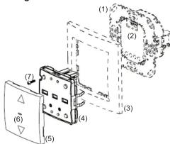
(1) Insert (see Accessories, not in scope of
delivery)
(2) Plug interface
(3) Frame (not in scope of delivery)
(4) Application module
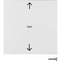
(5) Push-button design cover
(6) Status LED
(7) Screw for dismantling protection
(not for design lines R.1/R.3)
Function
System information
This device is a product of the quicklink system, in which installation devices communicate via radio signals.
quicklink stands for a configuration mode in which the function-related connection between transmitters and receivers is set on the device via push-buttons and displays without further tools.
All devices configurable via quicklink can be operated together in one system.
This device is compliant to the R&TTE-Directive 1999/5/EG. The Declaration of Conformity and further system information can be found on our homepage www.berker.de.
The device may be used in all EU and EFTA
countries.
Correct use
- Application module for blind inserts or power supply for radio application module
- Manual and automatic operation of blind/shutter motors connected to insert
- Transmission and reception of manual, time-controlled and automatic operation commands via quicklink
- Unsuitable for lighting control
- Only suitable for use in indoor areas, no drip or spray water
The quicklink configuration of the devices must only be carried out by qualified electricians.
Product characteristics
- quicklink functions for integration into the remote and group control of blinds/shutters
- Integration into scenes
- Party function to prevent unintentional operation of roller shutters through automated operation commands as well as radio/extension unit commands
- Memory function for easy time control of connected shutters
- Brightness-dependent operation when using a radio sun sensor
- LED display of insert/application module compatibility
Operation
Operating concept
The operation of the top or bottom push-button operation area is validated differently for each button. Simultaneous pressing of both push-button operation areas on a blind insert controls special functions such as memory or party function.

Figure 2: Operating element
(8) Push-button operation area ▲ for UP
(9) Status LED
(10) Push-button operation area ▼ for DOWN
Operation on a blind insert and power supply for radio application module
■ Press push-button operation area ▲ or ▼
Short-press (shorter than 0.4 s): jog mode and adjustment of slat positions.
Long-press: lock, shutter moves to fi nal
Maximum run time in lock-time is 2 minutes.
■ Short press on push-button operation area ▲
or ▼ during the shutter movement.
The shutter stops at the position reached.
If a protection signal (wind, rain) is present, no move commands are executed (see Setting Operating Mode).
Memory function
| Press both push-button operation areas | Status LED display | Function and LED display |
| 0 ... 5 s Running/recording of memory function is finished, the Status LED goes out and the radio blind push-button changes to normal operation. | ||
| 5 ... 10 s until the Status LED flashes orange for the first time | Memory function is executed; the LED is on. The Status LED flashes for 3 s: memory is empty and the radio blind push-button returns to normal operation. | |
| 10 ... 15 s until the Status LED flashes orange for the second time | Memory function operation times are recorded, the Status LED flashes orange for 2 s. Memory is full. Only 10 operation times can be recorded. The radio blind push-button changes back to normal operation. | |
| 15 ... 20 s until the Status LED flashes orange for the third time | The Status LED flashes for 3 s: memory function is deleted and the radio shutter push-button changes to normal operation. | |
Table 1: Operation of memory function
Information for electricians
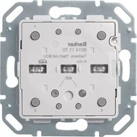
Overview of the operating elements beneath the design cover

Figure 3: Operating elements for radio configuration
(11) Press-activation points of the push-button operation areas
(12) fct button and fct LED
(13) cfg button and cfg LED
Mounting
Selecting mounting location
A minimum distance between the transmitter and corresponding receiver of about 1m must be maintained.
A minimum distance to electronic devices which emit high frequency signals such as computers, electronic transformers or microwave devices of approx. 0.5m must be maintained.
Mounting on or close to metal surfaces may cause impairment of the radio transmission.
Take material penetration into account. The range of the system can be optimised by selecting the best possible mounting location:
| Materiale Material Degree of material penetration | |
| Wood, plaster, plaster-board, uncoated glass | approx. 90% |
| Brick, press boards approx. | 70 % |
| Reinforced concrete, floor heating | approx. 30 % |
| Metal, metal grids, aluminium laminates, coated glass | approx. 10 % |
| Rain, snow approx. 1 ... 40 % | |
Table 3: degree of material penetration
Assembly of the device (Figure 1)
The insert is installed (see operating instructions for the insert).
■ Attach application module (4) together with frame (3) to a suitable shutter insert (see Accessories) so that the contact pins are inserted into the available jack (2).
As soon as voltage is supplied to the radio shutter push-button, the cfg LED (Figure 3, 13) indicates whether the radio shutter push-button and the insert are compatible with each other. In the meantime, the operating mode can be changed if necessary (see Setting Operating Mode).
| Display LED cfg cfg LED display | Significato Meaning |
| cfg LED flashes green for 5 s | Compatible |
| cfg LED flashes red for 5 s | Not compatible |
| LED blinks orange for 5 s | Compatible, but not configured to each other. For a new confi guration, the application module must be reset to factory settings. |
■ If available, fix dismantling protection with screw (7).
■ After configuration, click the design cover (6) into place on the application module (2).
Setting Operating Mode
It is possible to change between two operating modes during commissioning:
- Protection Mode (factory setting):
Mode for using sensors on the extension unit inputs of the insert to protect against wind or rain damage on outside blinds/awnings.
In protection mode no move commands are executed while a signal (wind /rain sensor) is present on the extension unit input. - Manual Mode
The last move command is executed regardless of whether or not it takes place locally or via an extension unit.
The application module was attached to the insert, the insert/application module detection is executed.
■ While the LED (6) is flashing green, hold the push-button operation area ▲ and ▼ simultaneously for approx. 5 s until the LED flashes orange.
The operating mode is changed and displayed:
The LED flashes 2x. The protection mode is set.
or:
The LED flashes 1x. The manual mode is set.
In normal operation, the operating mode cannot be displayed.
Radio configuration - quicklink
The radio configuration sets the functional connection between commanding (transmitters) and function-executing (receivers) radio components. Thus wireless e.g. central unit, group unit, extension unit and time controls can be realised.
e following can be configured:
- The local operation of the load connected to the insert
- Radio commands to control other receivers
- Functions that are executed when radio commands are received
For configuration by means of Hager connection device TX100 or ETS, additional functions are available (see operating instructions for TX100 or application description for ETS).
Configuring the radio blind push-button as a receiver Configuration to control the load connected to the insert (Table 4):
- via reception of a radio command
- via the local operation
Local operation is a function that is pre-configured at the factory and can be changed. As an example, the configuration of a wall transmitter and the radio shutter push-button as receiver is described below.
The design cover of the radio shutter push-button is not attached.
Configuration of radio shutter push-button as a transmitter
If the radio shutter push-button is operated as a transmitter, it can support the following functions for the receivers:
UP/DOWN (switch)
As an example, the configuration of the radio shutter push-button with receivers for which the supported displays occur through the cfg LED and fct LED is described here. Different configuration displays, such as for receivers with display, are to be taken from the receiver operating instructions.
Deleting a configuration
To delete a configured receiver or the local operation, execute the configuration again.
■ Start configuration (see configuration of radio button as a receiver).
■ If necessary Select transmitter button.
■ Select function on receiver: Select the function Delete on the receiver and confirm function on the receiver.
■ Finish configuration: Short press on cfg button on the transmitter.
Configuring group functions
By means of a group function, one transmitter controls several receivers. To do so, the same function must be configured on all receivers.
■ Start configuration (see configuration of radio button as a receiver).
■ If necessary Select transmitter button.
■ Select function on receiver: Select the group function as described above on each receiver to be integrated and confirm function on the receiver.
■ Finish configuration: Short press on cfg button on the transmitter.
Configuration of scenes
Individual settings for lighting and the position of shutters can be combined into scenes. Two different scenes can be created via quicklink and called up by pressing a button on the transmitter. A scene is created by configuring a push-button operation area of a transmitter (radio command) in the corresponding receivers with the scene function (see Table 5: Configure the function for the radio blind button).
■ Start configuration
■ Select transmitter button: Select the button for the scene command.
■ Select function on receiver: Select the scene function as described above on each receive to be integrated and confirm function on the receiver.
■ Finish configuration: Short press on cfg button on the transmitter.
Changing/saving scenes
Switching, dimming and blind statuses of the receivers in a scene can be changed and saved.
■ The load status can be configured locally or by remote control on the receivers integrated into the scene, e.g. light 1 = 60 % brightness level, light 2 = 40 % brightness level, blind down.
- Keep transmitter button belonging to the configured scene command pressed for more than 5 seconds.
A brief status changeover of the receiver signals the successful saving of the scene.
| fct LED display | Configurable function | Function resulting from transmitter operation, notes | |
| ▲ | Move UP, stop | Short press on button: adjustment of the slat position / stopLong press on button: lock, shutter moves to top final position. | |
| ▼ | DOWN, stop | Short press on button: adjustment of the slat position / stopLong press on button: lock, shutter moves to bottom final position. | |
| 1 | Scene 1 | Receiver is allocated to a scene due to the confi guration of the function.Short press on push-button: calling up the saved state of the con- nected load for the scene | |
| 2 | Scene 2 | ||
| ◆ | Shutter switch | Radio shutter switch is assigned to a compatible transmitter. Up/ down function is assigned to one confi guration operation. | |
| UP forced mode | Moves the shutter to the appropriate fi nal position with higher-level priority. The execution of other commands is only possible when forced operation is reset. | ||
| DOWN forced mode | |||
| Memory function | Activates/deactivates execution of the memory function (see Memory function). Recording cannot be activated by radio command. | ||
| ☒ | Delete. | No functionAssignment to transmitter is deleted | |
Table 4: Configurable receiver functions
Setting the shutter position for scenes
If the radio shutter button is assigned to a scene as a receiver, then the shutter position can be set for this scene.
■ Move the shutter to the top final position and wait for two minutes.
■ Move the shutter downwards to the desired position.
■ Set the desired slat position by pressing the button briefly several times (max. 30 UP steps)
Keep transmitter button belonging to the configured scene command pressed for more than 5 seconds.
The shutter moves up for a second and then down for a second. The scene position has been saved.
Locking/unlocking scene changes
To prevent unwanted changes to a scene, the changing of the scene can be locked.
Step Result
Start configuration
■ Short press on cfg button on the wall transmitter.

If there is no further activation, the configuration is automatically ended after 10 minutes.
Select transmitter button
■ Short press on press-activation point on the wall transmitter which should activate the Up function.

Select function on receiver
■ Repeated short press on fct button on the radio blind button until the desired UP-function is displayed (Table 4).

Confirming function on receiver
■ To confirm, keep the fct button pressed for more than 2 seconds.

Finish configuration
■ Short press on cfg button on the wall transmitter again.

■ Start configuration.
■ Select transmitter button: Select the button for the scene command.
■ Select function on receiver: When the function Scene 1 or Scene 2 is indicated by the fct LED blinking in green colour, keep the fct button on the receiver pressed for more than 5 seconds until the cfg LED blinks briefly.
Then the fct LED indicates the currently configured status:
1 x blinking: Possible to change and save
2 x blinking: Changing the scene is locked.
■ Press fct button and select the desired setting. The setting changes each time the button is pressed.
■ To accept the selected setting time, keep the fct button pressed for more than 2 seconds.
■ Finish configuration: Short press on cfg button on the transmitter.
The cfg LEDs on the wall transmitter and the radio button light up in red colour.
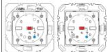
All receivers within radio range also indicate the configuration mode.
The cfg LED on the wall transmitter blinks for 1 second.

If it has already been configured, the fct LED of the radio blind button indicates the currently configured function.

After each activation, the fct LED indicates the function.
If the transmitter button has already been confi gured with a function in a different receiver and/or the confi gured function is part of a group control, only this function can be confi gured. To change a function, the existing confi guration must be deleted and the new one needs to be confi gured.
The cfg LED blinks during the saving process (approx. 5 s). The fct LED confi rms the function selection by displaying the corresponding colour.
1 Rapid blinking of the cfg LED indicates an impossible combination or an error.
The cfg LEDs on the wall transmitter, the radio blind button and all receivers within radio range go out. The function is configured.
If required, configure the Down function in the same way.
Resetting to factory settings
By factory default, the button is preconfigured for the operation of a shutter insert (see Operation).
■ Press the cfg button for more than 10 seconds. The cfg LED blinks red. If the system is reset to the factory setting, the LED goes out again.
This process deletes the complete configuration of the device.
Reconfiguration can only commence 15 seconds after the device is reset or switched on
Appendix
Technical data
Radio frequency 868 MHz
Radio protocol KNX radio
Connection Mounting on suitable inserts (see Accessories)
Power supply via insert
quicklink logic functions max. 20 transmitters/receivers
Receiver category 2
Transmitter duty cycle < 1%
Change-over time min. 600 ms
Blind operating time 2 min
Jog mode/slat adjustment time 250 ms
Relative humidity 0 ... 65 % (no condensation)
Ambient temperature 5 ... +45 °C
Storage/transport temperature -25 ... +70 °C
Step
Start configuration
■ Short press on cfg button on the radio shutter button.

If there is no operation, configuration is automatically ended after 10 minutes.
Select function on receiver
■ Short press on fct button on the receiver to select the UP/DOWN (switch) function (see the receiver operating instructions).

Confirming function on receiver
■ To save the allocation of command and function keep the fct button on the receiver pressed for more than 2 seconds.
Chiusura configurazione
■ Short press on cfg button on the radio shutter button.

Accessories
Shutter insert Comfort 8522 11 0..
Power supply
for radio application module 8502 01 0.. Radio brightness sensors 8580 11 00
...
warranty
We reserve the right to make technical and formal changes to the product in the interest of technical progress.
Our products are under guarantee within the scope of the statutory provisions.
If you have a warranty claim, please contact the point of sale or ship the device postage free with a description of the fault to the appropriate regional representative.
[Non-Text]
[Non-Text]
[Non-Text]
[Non-Text]
[Non-Text]
[Non-Text]
[Non-Text]
[Non-Text]
[Non-Text]
[Non-Text]
[Non-Text]
[Non-Text]
[Non-Text]
Result
The cfg LEDs on the radio shutter button and the receivers within radio range light up in red colour. On the fct LED of the radio shutter button, the current local operation is also shown (factory setting Up/Down switch, fct LED red/green).
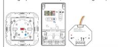
After each operation, the fct LED indicates a function.
Configuration of blind operation is carried out simultaneously for both the UP and DOWN pushbutton operation areas.
The Ground Truth image displays a single, solid horizontal line. According to Rule 2 (UNDERSCORE & LINE RULES), this is a stylistic or background line, not a placeholder underscore. Therefore, the OCR result must ignore it and output nothing or only meaningful text. The provided OCR content is "____", which consists of four underscores. This is an incorrect interpretation of the line as a placeholder, violating the rule that stylistic lines must be ignored. The OCR has hallucinated placeholder underscores where none exist in the GT, violating the rule to ignore such lines. Hence, the OCR result is inconsistent with the Ground Truth.
The Ground Truth image displays a single, solid horizontal line. According to Rule 2 (UNDERSCORE & LINE RULES), this is a stylistic or background line, not a placeholder underscore. Therefore, the OCR result must ignore it and output nothing or only meaningful text. The provided OCR content is "____", which consists of four underscores. This is an incorrect interpretation of the line as a placeholder, violating the rule that stylistic lines must be ignored. The OCR has hallucinated underscores where none should exist based on the GT's visual context. Hence, the OCR result is inconsistent with the Ground Truth.
The cfg LED blinks. After successful saving, the fct LED signals the saved function.
Rapid blinking of the cfg LED indicates an impossible combination or an error.
The cfg LEDs on the radio shutter button and all receivers within radio range go out. The radio command for the radio shutter button has been configured.
The Ground Truth image displays a single, solid horizontal line. According to Rule 2 (UNDERSCORE & LINE RULES), if the GT contains lines used for stylistic emphasis or as background elements (like ruled paper), the OCR result must ignore them. The line in the GT is clearly a stylistic/background line, not a placeholder for text. Therefore, the OCR should not have output any underscores. Outputting `____` constitutes an error under Rule 2, as it hallucinates placeholder symbols where none are semantically intended. Hence, the OCR result is inconsistent with the Ground Truth.
Table 6: Configuring the radio blind button as a transmitter
Table 5: Configuration of the function for the radio shutter push-button


- Safety instructions
- Design of the device
- Function
- System information
- Correct use
- Product characteristics
- Operation
- Operating concept
- Operation on a blind insert and power supply for radio application module
- Information for electricians
- Mounting
- Selecting mounting location
- Assembly of the device (Figure 1)
- Setting Operating Mode
- Radio configuration - quicklink
- Configuration of radio shutter push-button as a transmitter
- Deleting a configuration
- Configuring group functions
- Configuration of scenes
- Changing/saving scenes
- Setting the shutter position for scenes
- Locking/unlocking scene changes
- Step Result
- Resetting to factory settings
- Appendix
- Technical data
- Step
- Accessories
- ...
- warranty
Marque : HAGER
Modèle : 85245231
Catégorie : Interrupteur électrique