
80142180 - Interrupteur électrique HAGER - Notice d'utilisation et mode d'emploi gratuit
Retrouvez gratuitement la notice de l'appareil 80142180 HAGER au format PDF.


| Marque | Hager |
| Modèle | 80142180 |
| Type de produit | Disjoncteur modulaire |
| Nombre de pôles | 1 pôle |
| Courbe de déclenchement | Courbe C |
| Courant nominal | 16 A |
| Pouvoir de coupure | 6 kA |
| Tension nominale | 230/400 V AC |
| Fréquence | 50/60 Hz |
| Dimensions (H x L x P) | 85 x 18 x 70 mm |
| Poids | 0.1 kg |
| Alimentation | Filaire - raccordement par vis |
| Section de câble maxi | 25 mm² (rigide) / 16 mm² (souple) |
| Température de fonctionnement | -25 °C à +60 °C |
| Degré de protection | IP20 |
| Montage | Sur rail DIN symétrique 35 mm |
| Fonctions principales | Protection contre les surcharges et les courts-circuits |
| Entretien et nettoyage | Nettoyer à sec avec un chiffon doux ; ne pas utiliser de produits chimiques ou abrasifs |
| Sécurité | Disjoncteur bipolaire avec indication de position ; isolation renforcée |
| Pièces détachées et réparabilité | Non réparable par l'utilisateur ; contacter un électricien agréé |
| Informations générales | Conforme aux normes IEC/EN 60898-1 et NF C 61-121 |
FOIRE AUX QUESTIONS - 80142180 HAGER
Questions des utilisateurs sur 80142180 HAGER
0 question sur cet appareil. Repondez a celles que vous connaissez ou posez la votre.
Poser une nouvelle question sur cet appareil
Téléchargez la notice de votre Interrupteur électrique au format PDF gratuitement ! Retrouvez votre notice 80142180 - HAGER et reprennez votre appareil électronique en main. Sur cette page sont publiés tous les documents nécessaires à l'utilisation de votre appareil 80142180 de la marque HAGER.
MODE D'EMPLOI 80142180 HAGER
Operating and assembly instructions

natural_image
Technical line drawing of two electrical switch components (no text or symbols)
GB
8014 11 x0
KNX push button module 1gang
8014 21 x0
KNX push button module 2gang

e
Safety instructions GB
Electrical equipment may only be installed and assembled by a qualified electrician. Always follow the relevant accident prevention regulations of the country.
Failure to comply with these installation instructions may result in damage to the device, fire or other hazards.
When installing and laying cables, always comply with the applicable regulations and standards for SELV electrical circuits.
During renovation work, protect the device from pollution by paint, wallpaper paste, dust etc. The device can be damaged.
These instructions are an integral component of the product and must be retained by the end user.
Design and layout of the device
Figure 1: Design and layout of the device
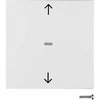
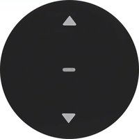
(1) Touch cover (not within scope of delivery)
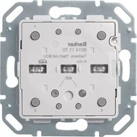
(2) Push-button module
(3) Fastening clamps
(4) Frame (not within scope of delivery)
(5) Supporting ring with prong connection
(6) Screw for dismantling protection
(7) Status LEDs
Function
System information
This device is a product of KNX system and corresponds to the KNX guidelines. Detailed specialised knowledge obtained from KNX training courses is required for comprehension. The planning, installation and commissioning are carried out with the help of KNX-certified software.
1

system link start-up
The function of the device is software-dependent. The software is to be taken from the product database. You can find the latest version of the product database, technical descriptions as well as conversion and additional support programmes on our website.
easy link start-up
The function of the device is confi guration-dependent. The confi guration can also be done using devices developed specially for simple setting and start-up.
This type of configuration is only possible with devices of the easy link system. easy link stands for easy, visually supported start-up. Preconfi gured standard functions are assigned to the in/outputs by means of a service module.
2


Correct use
- Operation of consumers, e.g. light on/off, dimming, blind up/down, saving and opening light scenes, etc.
- Installation into wall box according to DIN 49073
Product characteristics
- Start-up and programming in S-mode and E-mode
- Push-button functions: switching/dimming, blind control, value transmitter, scene call-up, specification of the heating operating mode, forced control, stepping switch and comparator function
- One status LED per rocker
- Function and colour of the status LEDs confi gurable for the device
- Integrated bus application unit
Operation
Triggering of functions and operation of electrical loads takes place via touch surfaces (fi gure 2, dashed) and can be set individually for each device.
There are two operating modes:
- Single-surface operation:
Switching lighting on/off and dimming brighter/darker is carried out alternately by repeated touching of a touch surface.
- Two-surface operation:
Two superimposed touch surfaces form a function pair. For example, touching the top surface switches/dims lighting on/makes it brighter, touching the bottom surface switches it off/makes it darker.
Operating a function or load
Consumers, such as lighting, blinds, etc., are operated using the touch surfaces, which are dependent on the device configuration.
■ Touch a touch surface.
The stored function is executed.
i The actuation pulse lasts for the duration of the actuation. Depending on the function, short and long touches can trigger different actions, e.g. switching/dimming.
Information for electricians GB
Installation and electrical connection

DANGER!
Touching live parts in the installation environment can result in an electric shock.
An electric shock can be lethal!
Disconnect the connecting cables before working on the device and cover all live parts in the area!
Connecting and installing the device
■ Mount the supporting ring (5) to a wall box in the correct position. Note marking TOP/OBEN.
■ Run the bus cable with the connecting terminal through the frame and connect it to the push-button module (2) at the back.
■ Attach the push-button module (3) with the frame (5) to the supporting ring until the fastening brackets (4) engage.
■ Fix dismantling protection with screw (6) if desired.
■ Reattach touch cover (1) to push-button module (2).
Dismantling
■ Remove touch cover (1) from push-button module.
■ Loosen screw for dismantling protection (6).
■ Remove push-button module (2) from supporting ring. Hold on to design frame.
Start-up
The device is connected and ready for operation. In general the following procedure is recommended.
system link - Loading the physical address and application software (Figure 3)
(8) Programming button
(9) Programming LED
The physical address is only ever assigned for one device. Only one device can ever be in programming mode.
It is advisable to program the physical address before installation.
■ If available, release the touch cover using the programming button (8).
■ Switch on bus voltage.
■ Press programming button (8). The programming LED (9) lights up.
If the programming LED does not light up, no bus voltage is present.
- Load the physical address into the device. The programming LED goes out.
- Load application software. Note down the physical address on the labelling fi eld.
The loading of non-compatible application software is indicated by flashing of the status LEDs (7).
■ Reattach the touch cover.
easy link
Information on the system configuration can be taken from the extensive description of the service module easy link.
Appendix
Technical data
| KNX Medium TP 1 |
| Start-up mode system link, easy link |
| Rated voltage KNX DC 21 ... 32 V SELV |
| Current consumption KNX typ. 10 mA |
| Connection mode KNX bus connecting terminals |
| Dimensions (W x H x D) 71 x 71 x 32 mm |
| assembling height from supporting ring 11 mm |
| Degree of protection IP 20 |
| Protection class | III |
| Operating temperature | -5 ... +45 °C |
| Storage/transport temperature | -20 ... +70 °C |
| Standards | EN 60669-2-1; EN 60669-1EN 50428 |
Troubleshooting
Bus operation is not possible.
Cause: Bus voltage is not present.
Check bus connection terminals for correct polarity.
Check bus voltage by brief y pressing the programming button (8), red programming LED (9) lights up if bus voltage is present.
Accessories
| Cover 1gang with lens | 8096 02 xx |
| Cover 2gang with lens | 8096 03 xx |
Warranty
We reserve the right to make technical and formal changes to the product in the interest of technical progress.
Our products are under guarantee within the scope of the statutory provisions.
If you have a warranty claim, please contact the point of sale or ship the device postage free with a description of the fault to the appropriate regional representative.

- Safety instructions GB
- Design and layout of the device
- Function
- System information
- system link start-up
- easy link start-up
- Correct use
- Product characteristics
- Operation
- Operating a function or load
- Information for electricians GB
- Installation and electrical connection
- DANGER!
- Connecting and installing the device
- Dismantling
- Start-up
- system link - Loading the physical address and application software (Figure 3)
- easy link
- Appendix
- Technical data
- Troubleshooting
- Bus operation is not possible.
- Accessories
- Warranty
Marque : HAGER
Modèle : 80142180
Catégorie : Interrupteur électrique