
AT1-5AS5E-GI - Appareil de mesure électrique INTERMATIC - Notice d'utilisation et mode d'emploi gratuit
Retrouvez gratuitement la notice de l'appareil AT1-5AS5E-GI INTERMATIC au format PDF.


| Type de produit | Minuterie programmable 24h |
| Marque | Intermatic |
| Modèle | AT1-5AS5E-GI |
| Alimentation | 120 V CA, 60 Hz |
| Courant nominal | 15 A |
| Puissance maximale | 1800 W (résistif) / ½ HP (moteur) |
| Dimensions (L x l x H) | 11,4 x 7,6 x 5,1 cm |
| Poids | 0,3 kg |
| Matériau du boîtier | Plastique ABS résistant aux chocs |
| Type de montage | Mural ou encastré |
| Fonctions principales | Programmation 24h, marche/arrêt, priorité manuelle, indicateur LED |
| Entretien et nettoyage | Nettoyer avec un chiffon doux et sec. Ne pas utiliser de liquide. |
| Sécurité | Conforme CE, protection contre les surcharges, coupe-circuit intégré |
| Pièces détachées | Contactez le service client Intermatic |
| Réparabilité | Réparation par un électricien qualifié recommandée |
| Garantie | 1 an (hors usage domestique) |
| Type de contact | Unipolaire unidirectionnel (SPST) |
| Température de fonctionnement | -10°C à 40°C |
| Degré de protection | IP20 (usage intérieur) |
| Nombre de programmes | Jusqu'à 12 cycles ON/OFF par jour |
FOIRE AUX QUESTIONS - AT1-5AS5E-GI INTERMATIC
Questions des utilisateurs sur AT1-5AS5E-GI INTERMATIC
0 question sur cet appareil. Repondez a celles que vous connaissez ou posez la votre.
Poser une nouvelle question sur cet appareil
Téléchargez la notice de votre Appareil de mesure électrique au format PDF gratuitement ! Retrouvez votre notice AT1-5AS5E-GI - INTERMATIC et reprennez votre appareil électronique en main. Sur cette page sont publiés tous les documents nécessaires à l'utilisation de votre appareil AT1-5AS5E-GI de la marque INTERMATIC.
MODE D'EMPLOI AT1-5AS5E-GI INTERMATIC
AT1-5 INSTRUCTIONS FOR USE
⚠ WARNING Risk of Fire or Electric Shock
■ Disconnect power at the circuit breaker(s) or disconnect switch(es) before installing or servicing.
■ More than one circuit breaker or disconnect switch may be required to de-energize the equipment before servicing.
■ Installation and/or wiring must be in accordance with National and Local Electrical Code requirements.
■ The device shall be installed in compliance with the enclosure, mounting, spacing and segregation requirements of the ultimate enclosure.
Thank you for having chosen an Intermatic electronic product. Before installing the instrument, please read these instructions carefully to ensure maximum performance and safety.
DESCRIPTION
| RL3 | INTERMATIC | |
| II° | Iae |
Fig.1 — Front panel
i
-
[NO TEXT]
▲N
□
×
INDICATIONS
1
Thermostat output
PL7. Availability output
RCE Auxiliary output
Alarm
INSTALLATION
■ Insert the controller through a hole measuring 71 mm x 29 mm.
■ Make sure that electrical connections comply with the paragraph "wiring diagrams". To reduce the effects of electromagnetic disturbance
keep the sensor and signal cables well separate from the power wires
■ Fix the controller to the panel by means of the suitable clips, by pressingly gently; if fitted, check that the rubber gasket adheres to the
panel perfectly. in order to prevent debris and moisture infiltration to the back of the instrument.
■ Place the probe T1 inside the room in a point that truly represents the temperature of the stored product.
■ Place the probe T2 on the evaporator where there is the maximum formation of frost.
OPERATION
TISTELV
During normal operation, the display shows either the temperature measured or one of the following indications
| DEF | Defrost in progress | HI | Room high temperature alarm |
| REC | Recovery after defrost | LO | Room low temperature alarm |
| OFF | Controller in stand-by | E1 | Probe T1 failure |
| CL | Condenser clean warning | E2 | Probe T2 failure |
| DO | Door open alarm |
The Ground Truth image displays a single, solid horizontal line. According to Rule 2 (UNDERSCORE & LINE RULES), this is a stylistic or background line, not a placeholder underscore. Therefore, the OCR result must ignore it and output nothing or only meaningful text. The provided OCR content is "\_\_\_\_", which consists of four underscores. This is an incorrect interpretation of the line as a placeholder, violating the rule that stylistic lines must be ignored. The OCR has hallucinated underscores where none should exist based on the GT's visual context. Hence, the OCR result is inconsistent with the Ground Truth.
INFO MENU
The information available in this menu is:
| T1 | Instant probe 1 temperature | TLO | Minimum probe 1 temperature recorded |
| T2 | Instant probe 2 temperature | CND | Compressor working weeks |
| THI | Maximum probe 1 temperature recorded | LOC | Keypad state lock |
Access to menu and information displayed
■ Press and immediately release button ⓘ.
■ With button ▼ or ▲ select the data to be displayed.
■ Press button ⓘ to display value.
■ To exit from the menu, press button ☒ or wait for 10 seconds.
Reset of THI, TLO, CND recordings
■ With button ▼ or ▲ select the data to be reset
■ Display the value with button 📄.
■ While keeping button i pressed, use button x
SETPOINT (display and modification of desired temperature value)
■ Press button ☑ for at least half second, to display the setpoint value.
■ By keeping button pressed, use button or to set the desired value (adjustment is within the minimum SPL and the maximum
SPH limit).
■ When button is released, the new value is stored
STAND-B
Button, when pressed for 3 seconds, allows the controller to be put on a standby or output control to be resumed (with \$B=YES only).
KEYPAD LOCK
The keypad lock avoids undesired, potentially dangerous operations, which might be attempted when the controllers is operating in a public place. In the INFO menu, set parameter LOC=YES to inhibit all functions of the buttons. To resume normal operation of keypad, adjust setting so that LOC=NO.
DEEROST
Timed defrost. Defrosting starts automatically when necessary time has elapsed to obtain the defrosting frequency set with DFR. For example, with DFR=4 defrosting occurs once every 6 hours. The internal timer is set to zero when power is applied to the controller and a each subsequent defrost start. When the controller is put on a standby, the accumulated time count is "frozen" (is not incremented).
Manual defrost. Defrosting may also be induced manually by keeping the button pressed for 2 seconds.
Defrost type. Once defrost has started, Compressor and Defrost outputs are controlled according to the parameters DTY and OAU. The AUX output is associated to defrost function with OAU=DEF exclusively.
Defrost termination. Defrost lasts as long as time DTO but, if the evaporator probe has been enabled (T2=YES) and temperature DLI is achieved before this time elapses, defrost will be terminated in advance. Caution: if C-H=HEA all defrost functions are inhibited; if DFR=C the timed defrost function is excluded; during defrost, the high temperature alarm is inhibited.
CONFIGURATION PARAMETERS
(No text)
■ The setup menu is accessed by pressing button Ⓧ + ∥ for 5 seconds.
■ With button ▼ or ▲ select the parameter to be modified.
■ Press button 🐎 to display the value
■ By keeping button pressed, use button or to set the desired value
■ When button LJJ is released, the newly programmed value is stored and the following parameter is displayed
■ To exit from the setup, press button ☒ or wait for 30 seconds.
PAR RANGE DESCRIPTION
| SCL 1 | °C; | Readout scale. |
| 2°C; °F | 1°C (only with INP=SN4A: measuring range -50/-9.9 ... 19.9/80°C) | |
| 2°C (measuring range -50 ... 120°C) | ||
| °F (measuring range -50 ... 120°C) | ||
| Caution: upon changing the SCL value, it is then absolutely necessary to reconfigure the parameters relevant to the absolute and relative temperatures (SPL, SPH, SP, ALA, AHA, etc.). | ||
| SPL | -50 .SPH | Minimum limit for SP setting (-5°C) |
| SPH | SPL, 120° | Maximum limit for SP setting (0°C) |
| SP | SPL, SPY | Setpoint (value to be maintained in the room), (0.0°C) |
| C-H | REF, HEA | Refrigerating (REF) or Heating (HEA) control mode |
| HYS | 1...16° | OFF/ON thermostat differential (0°C) |
| [IMAGE] | ||
| Refrigerating control (C-W=REF) Heating control (C-W=HEA) | ||
| CRT | 0...30min | Compressor rest time. The output is switched on again after CRT minutes have elapsed since the previous switchover. We recommend to set CRT=0.03 with HY5-2.0°, (3) |
| CT1 0 | .30min | Thermostat output run when probe TI is 1 inch. With CT1=0 the output will always remain OFF. (3) |
| CT2 0 | .30min | Thermostat output stop when probe TI is faulty. With CT2=0 and CT1=0 the output will always be ON. Example: CT1=4, CT2=2. In case of probe TI failure, the compressor will cycle 4 minutes on ON and 6 minutes. (6) |
| CDS | 0..30min | Compressor stop delay after the door has been opened (active only if DS=YES). (1) |
| DFR | 0...24/124fs | Defrost frequency expressed in cycles/24 hours. (3) |
| DLI | -50...120° | Defrost end temperature. (0°C) |
| DTO | 1...120min | Maximum defrost duration. (20) |
| DTY | OFF: ELE: GAS | Defrost type Off: off cycle defrost (Compressor and Heater OFF): ELE: electric defrost* (Compressor OFF and Heater ON): GAS: hot gas defrost* (Compressor and Heater ON). *The defrost output is active if only OAB=DEF. |
| DDY | 0...60min | Display during defrost. If DDY=0, during defrost the temperature continues to be displayed. If DDY >0, during defrost the display shows DEF when defrost is over REC is displayed during DDY minutes. (10) |
| ATM | NON: ABS: REL | Alarm threshold management. NON: all temperature alarms are inhibited (the following parameter will be ADD): ABS: the values programmed in ALA and AHA represent the real alarm thresholds. REL: the values programmed in ALR and AHR are alarm differentials referred to SP and SP+HY. |
| [IMAGE] Temperature alarm with relative thresholds, refrigerating control (ATM=REL, C-H=REF). [IMAGE] Temperature alarm with relative thresholds, heating control (ATM=REL, C-H=HEA). | ||
| ALA | -50...120° | Low temperature alarm threshold (-50°C) |
| AHA | -50...120° | High temperature alarm threshold (120°C) |
| ALR | -12...0° | Low temperature alarm differential. With ALR=0 the low temperature alarm is excluded. (0°C) |
| AHR | 0...12° | High temperature alarm differential. With AHR=0 the high temperature alarm is excluded. (0°C) |
| ATD | 0...120min | Delay before alarm temperature warning. (30) |
| ADO | 0...30min | Delay before door open alarm warning. (5) |
| ACC | 0...52 weeks | Condenser periodic cleaning. When the compressor operation time, expressed in weeks, matches the ACC value programmed, ‘CC’ flashes in the display. With ACC=0 the condenser cleaning warning is disabled. (6) |
| SB | NO/YES | Stand-by button ☑ enabling. (YES) |
| DS | NO/YES | Door switch input enabling (closed when door is closed). (NO) |
| OAU | NON: 0-1: DEF: LGT: ALR; | AUX output operation NON: output disabled (always off). 0-1: the relay contacts follow the on/standby state of controller. DEF: output programmed for defrost control. LGT: output enabled for light control. ALR: contacts make when alarm condition occurs. |
| INP 54 | ST1 | Temperature sensor selection. With INP = SN4A, the probes must be the Informatic models SN4A, with INP = ST1, the probes must be the Informatic models ST1... |
| OS1 | -12.5.12.5°C | Probe T1 offset. (0°C) |
| T2 | NO/YES | Probe T2 enabling (evaporator). (NO) |
| OS2 | -12.5.12.5°C | Probe T2 offset. (0°C) |
| TLD | 1...30 min | Delay for minimum temperature (TLG) and maximum temperature (THG) logging. (5) |
| SIM | 0...100 | Display slowdown. (6) |
| ADR | 1...255 | AT1-5 address for PC communication. (1) |
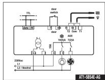
WIRING DIAGRAMS



y INTERMATIC
7777 Winn Road
Spring Grove, IL 60081
Intermatic Customer Service:
815-675-7000
www.intermatic.com
TECHNICAL DATA
The Ground Truth image displays a single, solid horizontal line. According to Rule 2 (UNDERSCORE & LINE RULES), this is a stylistic or background line, not a placeholder underscore. Therefore, the OCR result must ignore it and output nothing or only meaningful text. The provided OCR content is "\_\_\_\_", which consists of four underscores. This is an incorrect interpretation of the line as a placeholder, violating the rule that stylistic lines must be ignored. The OCR has hallucinated underscores where none should exist based on the GT's visual context. Hence, the OCR result is inconsistent with the Ground Truth.
Power supply
ATT-5...E 230Vac±10%, 50/60Hz, 3W
A11-5...U AT1.5.
ATT-5...D 12Vac±10%, 50/60Hz, 3W
[Non-Text]
Relay outputs
AT1-5.01(2)... compressor 12(4)A
AT1-5.S1(2)... Compressor 16(4)A AT1-5.08(4)
JCI-5.03(4)... compressor 12(5)W
AT1-5.\$3(4)... compressor 16(5)A AT1 5.05(E) compressor 12/8
AT1-5.63(0)... compressor 12(0)A
Art-5.55(6)... Compressor 1
Auxiliary 10a
AT1-5.0... maximum total current 12A
AT1-5.\$... maximum total current 16A
Inputs
NTC 10KΩ@25℃
PTC 1000Ω@25°C, Intermatic part No. ST1..
Measuring Range
-50...120°C,-55...240°F
-50 / -9.9 ... 19.9 / 80°C (with NTC10K only
[Non-Text]
-0.52C within the measurement range
Operating conditions
-10 ... +50°C; 15%...80% r.H.
CE - UL (Approvals and Reference Norms)
EN60730-1; EN60730-2-9;
EN55022 (Class
EN50082-1
UL 60730-
Front protection
IP55
AT1-5
INSTRUCTIONS FOR USE
MODE D'EMPLOI

158--01980


- AT1-5 INSTRUCTIONS FOR USE
- ⚠ WARNING Risk of Fire or Electric Shock
- Fig.1 — Front panel
- INDICATIONS
- INSTALLATION
- OPERATION
- TISTELV
- The Ground Truth image displays a single, solid horizontal line. According to Rule 2 (UNDERSCORE & LINE RULES), this is a stylistic or background line, not a placeholder underscore. Therefore, the OCR result must ignore it and output nothing or only meaningful text. The provided OCR content is "\_\_\_\_", which consists of four underscores. This is an incorrect interpretation of the line as a placeholder, violating the rule that stylistic lines must be ignored. The OCR has hallucinated underscores where none should exist based on the GT's visual context. Hence, the OCR result is inconsistent with the Ground Truth.
- INFO MENU
- STAND-B
- KEYPAD LOCK
- DEEROST
- CONFIGURATION PARAMETERS
- TECHNICAL DATA
- Measuring Range
- AT1-5
Marque : INTERMATIC
Modèle : AT1-5AS5E-GI
Catégorie : Appareil de mesure électrique