Pi2-5K D - Recepteur Ram Audio - Notice d'utilisation et mode d'emploi gratuit
Retrouvez gratuitement la notice de l'appareil Pi2-5K D Ram Audio au format PDF.


| Type de produit | Récepteur audio professionnel |
| Marque | Ram Audio |
| Modèle | Pi2-5K D |
| Dimensions (L x P x H) | 483 x 350 x 88 mm (19 pouces, 2U) |
| Poids | 12 kg |
| Alimentation | 230 V AC, 50/60 Hz |
| Puissance de sortie | 2 x 2500 W sous 4 ohms |
| Entrées audio | XLR symétriques |
| Sorties haut-parleurs | Speakon NL4 |
| Réponse en fréquence | 20 Hz – 20 kHz (±0.5 dB) |
| Distorsion harmonique totale | < 0.05 % |
| Protections | Thermique, court-circuit, surcharge, DC |
| Refroidissement | Ventilateurs à vitesse variable |
| Entretien et nettoyage | Dépoussiérage régulier avec un chiffon sec |
| Sécurité | Mise à la terre obligatoire, fusible externe |
| Pièces détachées et réparabilité | Disponibles auprès du service après-vente Ram Audio |
| Température de fonctionnement | 0 °C à 40 °C |
| Humidité relative | 10 % à 90 % sans condensation |
FOIRE AUX QUESTIONS - Pi2-5K D Ram Audio
Questions des utilisateurs sur Pi2-5K D Ram Audio
0 question sur cet appareil. Repondez a celles que vous connaissez ou posez la votre.
Poser une nouvelle question sur cet appareil
Téléchargez la notice de votre Recepteur au format PDF gratuitement ! Retrouvez votre notice Pi2-5K D - Ram Audio et reprennez votre appareil électronique en main. Sur cette page sont publiés tous les documents nécessaires à l'utilisation de votre appareil Pi2-5K D de la marque Ram Audio.
MODE D'EMPLOI Pi2-5K D Ram Audio

Professional Power Amplifiers
Pi Series
Pi2 3K-5K
Pi4 6K-10K

OPERATION MANUAL
BEDIENUNGSANLEITUNG
MANUAL DE EMPLEO
SAFETY PRECAUTIONS
SICHERHEITSHINWEISE
ADVERTENCIAS
WARNING:

The exclamation point inside an equilateral triangle indicates the existence of internal components whose substitution may affect safety.

The lightning and arrowhead symbol warns about the presence of uninsulated dangerous voltage.
ACHTUNG!:

Das Ausrufezeichen innerhalb eines Dreiecks weist darauf hin, dass der Austausch interner Bauteile die Sicherheit beeinflussen kann.

Das Blitzzeichen zeigt die Gegenwart unisolierter gefährlicher Spannungen an.
PRECAUCIÓN:

El signo de exclamación en el interior de un triángulo equilátero indica la existencia de componentes internos cuya sustitución puede afectar a la seguridad.

El símbolo de la flecha quebrada alerta acerca de la presencia de partes no aisladas con voltajes peligrosos.
CAUTION
RISK OF ELECTRIC SHOCK DO NOT OPEN
To avoid fire or electrocution risk do not expose the unit to rain or moisture.
To avoid electric shock, do not open the unit. No user servicable parts inside. In the case of disfunction, have the unit checked by qualified agents.
Class I device.
VORSICHT
GEFAHR EINES ELEKTRISCHEN SCHLAGES. NICHT ÖFFNEN!
Um Brand oder elektrische Schläge zu vermeiden, darf diese Einheit keiner starken Luftfeuchtigkeit oder Regen ausgesetzt werden.
Um elektrische Schläge zu vermeiden, öffnen Sie diese Einheit nicht. Bei Reparaturbedarf wenden Sie sich an qualifiziertes Personal.
Es handelt sich um ein Gerät der Klasse I.
ATENCIÓN
RIESGO DE CHOQUE ELÉCTRICO. NO ABRIR.
Para evitar incendio o riesgo de electrocución no exponga este equipo a la lluvia o la humedad.
Para evitar choques eléctricos no abra las cubiertas superior ni inferior. No hay partes reparables por el usuario. Acuda a personal técnico especializado.
Lea el manual antes de usar el equipo.
Dispositivo de Clase I.
INDEX
INHALTSVERZEICHNIS
ÍNDICE
0 Safety Precautions
1 General Information
1.1 Introduction
1.2 Main Characteristics
2 Controls: Where and What?
2.1 Front Panel
2.2 Rear Panel
3 Installation and Operation
3.1 Connections
3.1.1 Dual Channel Mode
3.1.2 Bridge Channel Mode
3.2 Configuration
4 Technical Specifications
4.1 Protection Systems
4.2 Data
0 Sicherheitshinweise
1 Allgemeine Anweisungen
1.1 Einleitung
1.2 Allgemeine Eigenschaften
2 Lokalisierung der Funktionen
2.1 Frontplatte
2.2 Rückplatte
3 Anschluss- und Inbetriebnahme
3.1 Anschlüsse
3.1.1 Dual Kanalmodus
3.1.2 Bridge Kanalmodus
3.2 Aufbau
4 Technische Spezifikationen
4.1 Schutzschaltungssysteme
4.2 Technische Daten
0 Advertencias de Precaución
1 Información general
1.1 Introducción
1.2 Características generales
2 Controles: ¿Dónde y qué?
2.1 Panel frontal
2.2 Panel trasero
3 Instalación y operación
3.1 Conexionado
3.1.1 Modo DUAL
3.1.2 Modo PUENTE
3.2 Configuración
4 Especificaciones técnicas
4.1 Sistemas de Protección
4.2 Datos técnicos
©2021 by C.E. Studio-2 s.l.
Pol.Ind. La Figuera
C/Rosa de Luxemburgo n°34
46970 Alaquas - Valencia - SPAIN
Phone: +34 96 127 30 54
Fax: +34 96 127 30 56
ramaudio.com
support@ramaudio.com
P-8004-155 QXPDQXDoc 4/21
RAM Audio ® , PMS ™ , SSP ™ , ICL ™ and QuantaPulse ™ are registered trademarks of C.E. Studio-2 s.l.. All other names are trademarks of their respective companies.
General Information
Allgemeine Anweisungen
Informaciones generales
1.1 Introduction
Pi is a multipurpose series of power amps for touring and installation applications, based on the legendary QuantaPulse™ switching mode power supply with an innovative class H 3 steps topology.
It includes a completely renewed PMS ™ which incorporates a set of protection systems which works in real time continuously maintaining all variables of the amp within safe working thresholds always.
Pi amps have been designed with a non-symmetrical class H topology which allows working with very high voltages given incredible headroom and a great punch.
All these characteristics make Pi amplifier an interesting device to work with asymmetric loads to squeeze every last drop of power in each way of the sound system.
Pi series has an extra-large 4.3" display with capacitive touch panel whereby it is possible to control and manage every parameter of the amp and its powerful FIR DSP, also controlled by our RAM_OCS software.
1.2 Main Characteristics
- Unmatched audio quality hi efficiency Class H 3-steps design.
- 2/4 Channels models from 3000W up to 10000W.
- Last generation QuantaPulse™ SMPS
- High voltage output for high headroom performances.
- Advanced Power Management System (PMS EVO™) with high effective protections system acting in real time.
- Up-side-down design to avoid fan dust accumulation.
- Industry standard Neutrik® XLR and Speakon® connectors.
- Powerful and fast response cooling system.
• 64 bits double-precision 96kHz FIR DSP - Extra-large 4.3" IPS display, capacitive touch panel user interface.
- Dante™ and AES3 inputs versions.
- Two Ethernet ports for daisy chain connection.
- USB port for firmware update and DSP control.
1.1 Einführung
Pi ist eine Mehrzweckreihe von Leistungsverstärkem für Touring- und Installationsanwendungen, die auf dem legendären QuantaPulse™ -Schaltmodus-Netzteil mit einer innovativen Klasse-3-Stufen-Topologie basiert.
Es enthält ein vollständig erneuertes PMS ™ , das eine Reihe von Schutzsystemen enthält, die in Echtzeit arbeiten und alle Variablen des Verstärkers kontinuierlich innerhalb sicherer Arbeitsschwellen halten.
Pi-Verstärker wurden mit einer nicht symmetrischen Klasse-H-Topologie entwickelt, die das Arbeiten mit sehr hohen Spannungen bei unglaublicher Kopffreiheit und großem Durchschlag ermöglicht.
All diese Eigenschaften machen den Pi-Verstärker zu einem interessanten Gerät für die Arbeit mit asymmetrischen Lasten, um den letzten Leistungsabfall in jeder Richtung des Soundsystems zu quetschen.
Die Pi-Serie verfügt über ein extra großes 4,3-Zoll-Display mit kapazitivem Touchpanel, mit dem alle Parameter des Verstärkers und seines leistungsstarken FIR-DSP gesteuert und verwaltet werden können, die ebenfalls von unserer RAM_OCS-Software gesteuert werden.
1.2 Allgemeine Eigenschaften
- Unübertroffene Audioqualität, hohe Effizienz Klasse H 3-Stufen-Design.
- Zwei- und Vierkanalmodelle von 3000W bis 10000W.
- QuantaPulse™ Schaltnetzteil der letzten Generation.
- Hochspannungsausgang für hohe Headroom-Leistungen.
- Fortschrittliches Leistungverwaltungsystem (PMS EVO™) mit hochwirksamem Schutzsystem in Echtzeit.
- Kopfüber Design, um Staubansammlungen des Lüfters zu vermeiden.
- Standard Neutrik® XLR- und Speakon®-Anschlüsse.
- Leistungsstarkes und schnell ansprechendes Kühlsystem.
• 64 Bit doppelt präzise 96kHz FIR DSP - Extra großes 4,3" IPS-Display, kapazitive Touchpanel-Benutzeroberfläche.
- Dante™- und AES3-Eingangsversionen.
- Zwei Ethernet-Ports für Daisy-Chain-Verbindung.
- USB-Port für Firmware-Update und DSP-Steuerung.
1.1 Introducción
Pi es una serie de amplificadores de potencia multiusos tanto para aplicaciones de touring como instalación. Están basados en la legendaria fuente de alimentación conmutada QuantaPulse™ con una innovadora topología en clase H de 3 pasos.
Incluye un sistema PMS™ completamente nuevo que incorpora un set de sistemas de protección que trabaja en tiempo real de forma continuada manteniendo todas las variables del amplificador dentro de umbrales de trabajo seguros siempre.
Los amplificadores Pi han sido diseñados con una topología en clase H no asimétrica que permite trabajar con tensiones muy altas dando una increíble dinámica y una excelente pegada.
Todas estas características hacen al amplificador Pi un interesante aparato para trabajar con cargas asimétricas y exprimir hasta la última gota de potencia en cada vía del sistema de sonido.
La serie Pi tiene una pantalla extra-grande de 4.3" con panel capacitivo táctil mediante el cual es posible controlar y gestionar cada parámetro del amplificador y de su potente DSP FIR, también controlado a través de nuestro software RAM_OCS.
1.2 Características principales
- Inigualable diseño en clase H 3 pasos de alta eficacia y calidad de sonido.
- Modelos de 2 y 4 canales con potencias de 3000 a 10000 W.
- Última generación de fuente de alimentación conmutada QuantaPulse™
- Alta tensión de salida para obtener una gran dinámica.
- Evolucionado Sistema de manejo de potencia (PMS EVO™) con sistema de protección de alta eficacia en tiempo real.
- Diseño up-side-down: evita acumulación de polvo sobre componentes.
- Conectores Neutrik® XLR y Speakon®
- Potente y veloz control de temperatura
- Proceso de DSP de 64 bits de doble precisión a 96 kHz.
- Pantalla IPS de 4.3" con interface a través de panel táctil capacitivo.
- Versiones con Dante™ y AES3.
- Dos puertos Ethernet para conexión daisy chain.
- Puerto USB para actualización del firmware y control del DSP.
Controls: Where and What?
Lokalisierung der Funktionen
Controles: ¿Dónde y qué?
2.1 Front Panel
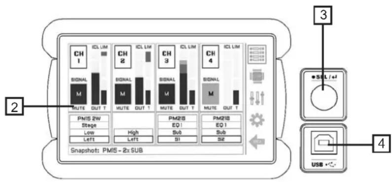
See Figure 1
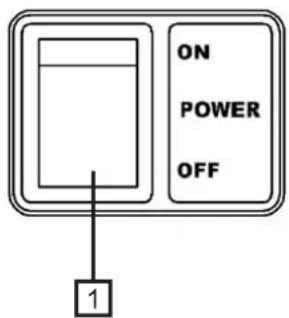
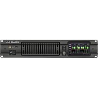
1 Main Power Switch: Position I: Connects the amplifier's current feed. Position O disconnects the Power.
2 Display: See pages 10, 11 and 12.
3 Encoder: to control de display menus.
4 USB Connector: for firmware update and DSP control.
2.1 Frontplatte
Siehe Fig. 1
1 Beleuchteter Hauptstromschalter: Position I: Schaltet die Endstufe ein. Position O Schaltet die Endstufe aus.
② Anzeige: Siehe Seiten 10, 11 und 12.
3 Encoder: Zur Steuerung der Anzeigemenüs.
4 USB-Anschluss: für Firmware-Update und DSP-Steuerung.
2.1 Panel frontal
Ver Figura 1
1 Interruptor principal:
Posición I: conecta la alimentación de corriente del amplificador.
Posición O: desconecta la potencia.
2 Pantalla: ver páginas 10, 11 y 12.
3 Encoder: para controlar los menús de la pantalla.
4 Conector USB: para actualizar el firmware y controlar el DSP.
1 Front Panel
Controls: Where and What?
Lokalisierung der Funktionen
Ubicación y función de los Controles
2.2 Rear Panel
See Figure 2
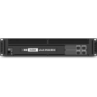
1 Signal Input: Female Neutrik® XLR Connectors for the amplifier's signal input.
② Speaker connectors: Neutrik®
Speakon to connect the speakers.
3 Ethernet ports: for daisy chain connection.
4 Dante Inputs (only in Pi+Dante version): Digital Inputs Dante™ Networking (AES67 and DDM compatible).
□ Mains Power Cord: to connect the amplifier to the mains network. The colour code is:
Blue: Neutral
Brown: Live, single phase
Yellow-green: Protective Earth
2.2 Rückplatte
Siehe Fig. 2
1 Eingangssignal: Neutrik®-XLR
Buchsen für den Signaleingang der Endstufe.
2 Lautsprecheranschluss: Neutrik Speakonstecker zum Anschluss an Lautsprecher.
3 Ethernet-Ports: für Daisy-Chain-Verbindung.
4 Dante-Eingänge (nur in Pi+Dante-Version): Digitale Eingänge Dante™ Networking (AES67- und DDM-kompatibel).
Netzkabel: Zum Anschließen des Verstärkers an das Stromnetz. Der Farbcode lautet:
Blau: Neutral
Brown: Live, einphasig
Gelbgrün: Schutzerde
2.2 Panel Trasero
Ver Figura 2
1 Entrada de señal: conectores Neutrik XLR hembra para la entrada de señal al amplificador.
2 Conectores Speakon: conectores Neutrik® Speakon para la conexión de altavoces.
3 Puertos Ethernet: para conexión daisy chain.
4 Entradas Dante (solo en la versión Pi+Dante): Entradas Digitales Dante™ Networking (compatible con AES67 y DDM).
Cable de red: para conectar el amplificador a la red eléctrica. El código de colores de este es:
Azul: neutro
Marrón: live, fase simple.
Amarillo-verde: protección de tierra.
2 Rear Panel

Installation and Operation
Anschluss und Inbetriebnahme
Instalación y operación
3.1 Connections
The Power switch must always be on the "Off" position before plugging the amp to a properly earthed mains socket (170-265V AC). The colour code is:
Blue: Neutral
Brown: Live, single phase
Yellow-green: Protective Earth
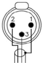
The input signal fed to the amplifier can be either balanced or un-balanced. The drawing below describes both ways to wire an XLR connector for the purpose.
Balanced Signal: Connect pin 1 to Ground, pin 2 to Signal + (hot) and pin 3 to Signal - (cold).
Unbalanced Signal: Connect Pin 1 to Ground, pin 2 to Signal and pin 3 to Ground.
3.1 Anschlüsse
Bevor Sie diese Einheit an eine SHUKO-Steckdose anschließen, schalten Sie den Hautstromschalter aus. The colour code is:
Blue: Neutral
Brown: Live, single phase
Yellow-green: Protective Earth
Das Eingangssignal kann entweder symmetrisch oder unsymmetrisch sein. Für den Anschluss siehe Zeichnung.
Symmetrisches Signal: Die Belegung der XLR Pins ist wie folgt: 1-Masse, 2-Positives Signal (hot), 3-Negatives Signal (cold).
Asymetrisches Signal: Die Belegung der XLR Pins ist wie folgt: 1-Masse, 2-Signal, 3-Masse.
3.1 Conexionado
Para proceder al conexionado de la unidad situe siempre el interruptor de alimentacion en la posicion "off". Conecte siempre el cable de alimentacion principal (170-265V AC) a una base provista de toma de tierra. El código de color es:
Azul: neutro
Marrón: vivo, fase simple.
Amarillo-verde: protección de tierra.
La conexión de la señal de entrada del amplificador se puede hacer con señal balanceada o no balanceada. La forma de realizar la conexión en ambos casos es la siguiente
Señal Balanceada: conectar el pin 1 a tierra, el pin 2 a la señal + (hot) y el pin 3 a la señal - (cold) (-).
Señal no Balanceada: conectar pin 1 a tierra, pin 2 a la señal y pin 3 a tierra.
Balanced Wiring
1- Ground
2- Signal +
3- Signal -

Unbalanced Wiring
1- Ground
2- Signal
3- Ground
Important!: If a connection is done with a un-balanced line and pin 3 on the XLR is not connected to ground, a 6 dB loss occurs in the line and only a quarter of the amplifier power is produced.
ACHTUNG! Wenn Sie ein asymetrisches Signal anschließen und Pin 3 nicht an Masse anschließen, erzeugt dies einen Verlust von 6dB (1/4 der Leistung der Endstufe) am Ausgangssignal.
¡Atención! : si se realiza una conexión con señal no balanceada y no se conecta el pin 3 del XLR a masa, se producirá una perdida de 6 dB en la señal (¼ de potencia del amplificador).
Installation and Operation
The amplifier can operate on two different configurations: DUAL, or BRIDGE. The connections for the two modes are different.
3.1.1 DUAL Channel Mode
See Figure 3
- By means of the display, set the Amplifier Mode to "DUAL".
- Connect the signal lines to the female XLR connectors on all channels.
- Connect the speakers' lines to the corresponding Speakon on the amp respecting the polarity.
- Use the level control knob on the front panel to adjust each channel independently.
3.1.2 BRIDGE Channel Mode
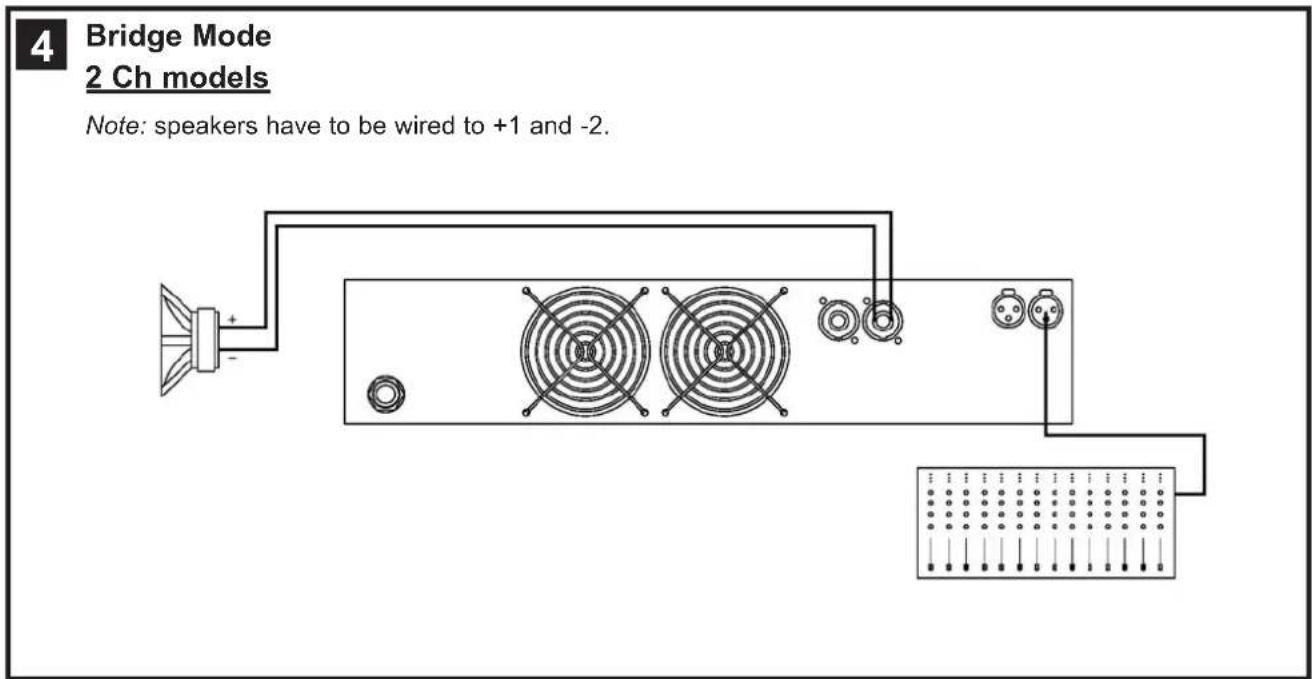
See Figure 4
- By means of the display, set the configuration mode to "BRIDGE"
- Connect a signal line to input female XLR Channel "A" (or Ch-C in 4 channel models).
- Connect the speaker line to the Channel A Speakon (or Ch-C in 4 channel models) wired to +1 and -2. In this way pin +1 is positive.
- Use Channel-A (or Ch-C in 4 channel modes) control knob to adjust the amp's output.
WARNING! The “-” pins, do not have to be Ground!
Anschluss und Inbetriebnahme
Es gibt zwei Funktionsmöglichkeiten dieser Endstufe: Dual, und Bridge. Die Anschlüsse sind in den zwei Fällen unterschiedlich.
3.1.1 DUAL Kanalmodus
Siehe Fig. 3
- Stellen Sie den Verstärkermodus über das Display auf „DUAL“.
- Schließen Sie alle Eingangssignale an ihre entsprechenden XLR-Buchsen.
- Schließen Sie die Lautsprecher an die entsprechenden Speakon an, bitte die Polarität ist beachten.
- Benutzen Sie die Lautstärkeregelung der entsprechenden Kanäle um den gewünschten Lautstärkepegel zu erreichen.
3.1.2 Bridge Kanalmodus
Siehe Fig. 4
- Setzen Sie den Konfigurationsschalter auf die Modus "BRIDGE".
- Schließen Sie das Eingangssignal an die XLR-Buchse "A" an (oder Kanal C bei 4-Kanalmodellen).
- Schließen Sie den Lautsprecher an den Kanal "A" Speakon (oder Kanal C bei 4-Kanalmodellen) verkabelt mit +1 und -2 (+1 ist positiv).
- Benutzen Sie Kanal A (oder Kanal C bei 4-Kanalmodellen) Potentiometer für die Regulierung des Endstufenausganges.
ACHTUNG! The “-” pins, do not have to be Ground!
Instalación y operación
Existen tres modos de funcionamiento posibles del amplificador: Dual, Paralelo, o Puente. Las conexiones en cada caso son diferentes.
3.1.1 Modo Dual (Stereo)
Ver figura 3
- Seleccione el Modo "DUAL" en el display.
- Conecte las señales de entrada de ambos canales por sus respectivos conectores, utilizando para ello los conectores XLR hembra de cada canal.
- Conecte los altavoces a los Speakon respectivas de cada canal respetando la polaridad.
- Utilice el control de nivel de cada canal para controlar independiente-mente los niveles de salida de cada altavoz.
3.1.2 Modo Puente (Bridge)
Ver figura 4
- Seleccione el Modo "BRIDGE" en el display.
- Conecte la señal de entrada al amplificador por el conector de entrada XLR hembra del Canal A (o canal C en una etapa de 4 canales).
- Conecte el altavoz al Speakon del canal A (o canal C en una etapa de 4 canales), cableando al +1 y -2. De esta forma el pin +1 es positivo.
- Use el botón de control del canal A (o canal C en las etapas de 4 canales) para ajustar la salida del amplificador.
¡ATENCIÓN! ¡Los pins “-” no tienen que ser tierra!


Dual Channel
4 Channel models


Bridge Mode
4 Channel models
Note: speakers have to be wired to +1 and -2.


Bridge + Dual Mode
3 Channels Mode
Note: in Bridge mode, speakers have to be wired to +1 and -2.

Installation and Operation
Instalación y operación
3.2 Configuration
By means of the display, user can configure amplifier and DSP parameters and monitoring them.
There are six different screens as follows:
3.2 Configuración
Desde la pantalla el usuario puede configurar los parámetros del amplificador y del DSP y monitorizar estos. Hay seis pantallas diferentes que son como sigue:
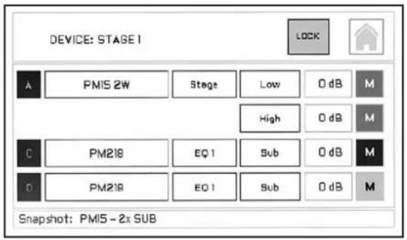
1. Default Screen:
Device Name: assigned by user via RAM_OCS
Lock Button: to lock touch screen
Home Button: to acess to Home screen
System Input Signal: shines green with signal presence
System Preset, Mode and Way names of current process
Level Control for amplifier channel output
Output Mute / Signal: shines green with output signal presence
Snapshot: shows the name of current Snapshot (if loaded one)
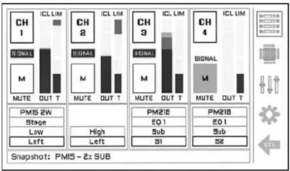
2. Home Screen:
Way Output Signal: shines green with signal presence
Mute Button: mutes the amplifier channel output
Output Channel Level
ICL Indicator: shines when clip limiter system is working
LIM: shows RMS/Peak limiters compression level
T: shows the channel temperature (percentage)
System Preset/Mode/Way/User ID Out names of current process
Snapshot: shows the name of current Snapshot (if loaded one)
Default Screen Icon: button to access to the Default screen

3. DSP Edit Screen:
Source Input: to select the analog/digital source input
System Input: to select the input of each system
User ID Input Label: shows the name assigned by the user
User EQ: to select the input EQ User Memory
Group Values: shows the control groups values (green if present)
JOIN (optional): to join different outputs to a single input
System Preset Selector
M: to select the Mode EQ
Way: to optionally select the output way
Installation and Operation
Instalación y operación

4. User Input Setting Screen:
User ID Input Label: shows the name assigned by the user
User EQ Access Button (see 4.1)
In: Input Level VUmeter
GAIN IN: to change the input gain
DELAY: to change the input delay (ms)
MIUTE: to mute input
Rev: to change input polarity

4.1. User EQ Screen:
EQ Memory Name
EQ ON/OFF: to anable/disable User EQ
On/Off HP 1-6: to access to specific filter and enable/disable it
Type: to assign the filter type to the selected EQ
FREQ: to assign the frequency to the selected EQ
GAIN: to assign the gain to the selected EQ
Q: to assign the Q to the selected EQ

5. Amp Info & Screen Config: (top section)
OPER. TIME: shows the amp operation time
SN / MODEL: shows serial number and model of the amp
HW / FW: shows the hardware and firmware versions
BACKLIGHT DIMMER: to change the screen brightness
AUTO OFF: to automatically tuen off the screen (selectable time)
AUTO LOCK: to automatically lock the screen after 60s

5.1. SNAPSHOT Tab:
Snapshot: shows the name of current Snapshot (if loaded one)
RECALL FROM LIB: to recall a Snapshot saved in the library
SAVE TO LIB: to save current amp setup to a Snapshot
DELETE SNAPSHOT MEM: to remove a library Snapshot
Installation and Operation
Instalación y operación
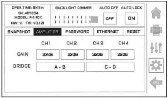
5.2 AMPLIFER Tab:
GAIN: to select amp gain (26dB to 44dB)
BRIDGE: to configure a pair of channels in Bridge mode
0dB FS IN (optional): to adjust the input digital reference
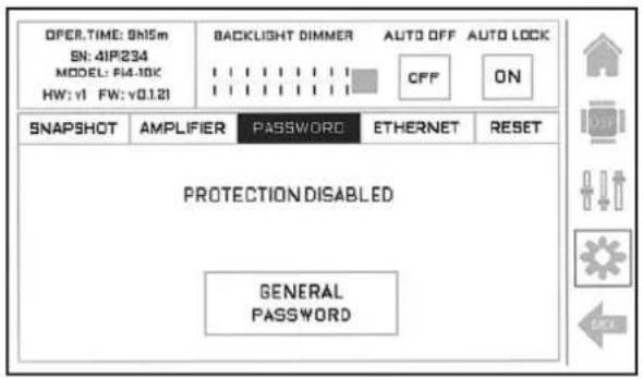
5.3 PASSWORD Tab:
GENERAL PASSWORD: to enable/disable the general password. When enable you have to introduce a 4-digits password and confirm it. When it is active user will limit the access to the amp through the screen and RAM_OCS PC software
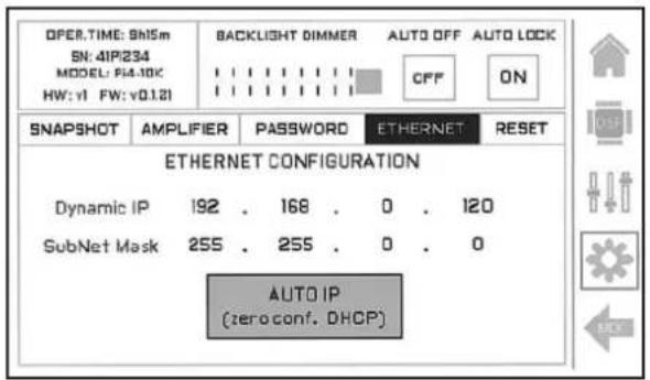
5.4 ETHERNET Tab:
Dynamic IP / SubNet Mask: information of the current IP address AUTO IP: to enable/disable the dynamic IP function:
- When Auto IP is enabled, amp will receive an IP from an external DHCP server. When no DHCP server is present in the network, amp will self-asignate an IP with the Zero config protocol.
- When Auto IP is disabled, you have to manually configure IP selecting each IP number and changing it with the encoder. To finish press the button APPLY IP.

5.5 RESET Tab:
FACTORY RESET: to reinstate initial factory parameters.
Caution! All the amp configurations and libraries will be lost.
Protection Systems
Schutzschaltungs- systeme
Sistemas de Protección
PMS EVO™ - Power Management System
This is a complete set of protections that monitors the main amp parameters (load status, signal input, temperature, current, etc.) in order to draw from the power supply only the precise amount of current required to maintain safe operation during hazardous or extreme working conditions.
This system controls the amount of power that the amp delivers under three basic circumstances:
1.- The power-on sequence, where output is inhibited until the amp circuits are ready to operate. This routine is repeated at every restart, not just when the power switch is activated.
2.- When internal temperatures rise to near thermal shutdown point due to unfavourable operating conditions. Here the system takes control, restricting current so as to maintain operational continuity at the precise power level which the amp is capable of withstanding at that particular moment.
3.- Excessive current consumption. This event usually occurs under laboratory conditions (long term sinusoidal signal testing with dummy loads) or, for example, in field applications in conditions of prolonged acoustic howl-round. Here PMS EVO™ system takes control to avoid any damage to the speakers and to prevent the mains breaker from tripping or the fuses blowing.
ICL2™ - Intelligent Clip Limiter
The RAM Audio ICL2 ™ is an anticlip system to avoid speaker failure and provide more acceptable sound quality even when clipping occurs. With the ICL2 ™ system you don't lose the music "punch" but the speakers are kept under control.
SSP™ - SOA Sentry Protection
SOA Sentry protection effectively limiting the power that the amp could deliver into an incorrect load or to a direct short-circuit. This avoids power transistor failure.
PMS EVO™ - Power Management System
Vollständiges Set von Schutzfunktionen das die wichtigsten Endstufenparameter überwacht (Auslastung, Signaleingang, Temperatur und Stomstärke) um vom Netzanschluss nur die Menge Strom zu beziehen, die für den betriebssicheren Arbeitsablauf notwendig ist
Dieses System reguliert die von der Endstufe abgegebenen Leistung in 3 Fällen:
1.- Anschaltevorgang: Der Ausgang wird gehemmt bis die Endstufe voll funktionsbereit ist. Dieser Vorgang wiederholt sich bei jedem Neustart, nicht nur wenn der Leistungsschalter aktiviert wurde.
2.- Wenn die Innentemperatur aufgrund ungünstiger Arbeitsbedingungen nahe des Grenzwertes steigt, bei dem die automatische Ausschaltefunktion aktiviert würde, um eine Überhitzung des Systems zu vermeiden. In diesem Fall übernimmt das System die Kontrolle und reduziert die Stromzufuhr auf ein Niveau, dass die Endstufe in dieser Situation aushalten kann.
3.- Überhöhter Stromverbrauch: Diese Situation tritt normalerweise unter Laborbedingungen (in sinusförmigen Langzeitsignaltests mit Dummylasten) oder in langanhaltenden akustischen Feedback Bedingungen. Hier greift das PMS EVO™ System ein um eine Schädigung der Lautsprecher zu vermeiden und um zu verhindern dass der Hauptunterbrecher ausgelöst wird oder die elektrischen Sicherungen durchbrennen.
ICL2™ - Intelligent Clip Limiter
Das RAM Audio ICL2™ ist ein Anticlipsystem das das Versagen der Lautsprecher vermeidet und auch wenn Clipping auftritt noch eine bessere Tonqualität gewährleistet. Mit dem ICL2™ System verlieren Sie den "Punch" nicht, und der Lautsprecher arbeitet kontrolliert.
SSP™ - SOA Sentry Protection
SOA Die Leistung, die die Endstufe an inkorrekte Lasten oder an einen Kurzschluss abgeben könnte wird wirksam limitiert. Dies verhindert die Zerstörung der Leistungstransistoren.
PMS EVO™ - Sistema manejo de potencia
Este es un completo set de protecciones que monitoriza los parámetros principales del amplificador (estado de la carga, señal de entrada, temperatura, corriente, etc.) para así sacar de la fuente de alimentación solo la cantidad de corriente requerida para mantener una operación segura durante condiciones extremas de trabajo.
Este sistema controla la cantidad de potencia que el amplificador entrega bajo tres circunstancias básicas:
1.- La secuencia de encendido, donde la salida es inhibida hasta que los circuitos del amplificador están preparados para operar.
2.- Cuando la temperatura interna llega casi al punto de bloqueo térmico debido a condiciones de operación desfavorables. Aquí el sistema toma el control restringiendo la corriente para mantener la continuidad operacional al nivel de potencia preciso en el que el amplificador es capaz de resistir este particular momento.
3.- Consumo de corriente excesivo. Este caso normalmente ocurre en condiciones de laboratorio (test con señal sinoidal durante largo tiempo con cargas ficticias) o, por ejemplo, en aplicaciones de campo en condiciones de re-alimentación acústica. Aquí el sistema PMS EVO™ toma el control para evitar cualquier daño en los altavoces y prevenir que el magnetotérmico salte o los fusibles se fundan.
ICL2™ - Limitador de clip inteligente
El ICL2™ es un sistema anticlip que evita daño en el altavoz y provee de una calidad de sonido más aceptable incluso cuando el clip está ocurriendo. Con el sistema ICL2™ no pierdes el "punch" de la música pero el altavoz es mantenido bajo control.
SSP™ - Protección SOA Sentry
El sistema SOA Sentry Protection limita de forma efectiva la potencia que el amplificador puede entregar frente a una carga incorrecta o a un corto-circuito. Este evita fallos en los transistores de potencia.
4.2 Data 4.2 Datos técnicos4.2 Techn
Daten
Technical Specifications
| Pi2-3K Pi2-5K Pi4-6K Pi4-10K | ||||
| Number of channels 2 | 2 | 4 | 4 | |
| Total output power 3000 W 5000 W 6000 W 10000 W | ||||
| Output Power* (All ch.'s driven/single channel) | ||||
| 2 ohms | 2 × 1450 W2 | 2 × 2500 W2 | 4 × 1450 W2 | 4 × 2500 W2 |
| 1 × 1450 W2 | 1 × 2500 W2 | 1 × 1450 W2 | 1 × 2500 W2 | |
| 4 ohms | 2 × 1500 W | 2 × 2500 W | 4 × 1500 W | 4 × 2500 W1 |
| 1 × 1750 W | 1 × 2800 W | 1 × 1900 W | 1 × 3000 W | |
| 8 ohms | 2 × 1100 W | 2 × 1600 W | 4 × 1100 W | 4 × 1600 W |
| 1 × 1150 W | 1 × 1700 W | 1 × 1200 W | 1 × 1800 W | |
| 4 ohms Bridged | 2900 W2 | 5000 W2 | 2 × 2900 W2 | 2 × 5000 W2 |
| 8 ohms Bridged | 3000 W | 5000 W | 2 × 3000 W | 2 × 5000 W1 |
| Hi-Z 70V | 2 × 1500 W | 2 × 2500 W2 | 4 × 1500 W | 4 × 2500 W2 |
| Hi-Z 100V | 2 × 800 W | 2 × 2500 W | 4 × 800 W | 4 × 2500 W1 |
| Max output voltage | 144 Vpeak | 176 Vpeak | 144 Vpeak | 176 Vpeak |
| Max output current | 38 Apeak | 50 Apeak | 38 Apeak | 50 Apeak |
| Total Harmonic Distortion | <0.05% | |||
| Voltage Gain | 26dB to 44dB (1dB step) | |||
| SNR | 106 dBA | 107.5 dBA | 106 dBA | 107.5 dBA |
| Required AC Mains | ||||
| Operating Voltage (50Hz-60Hz) | 170V-265V AC / 90V-140V AC | |||
| 1/8 Rated Power (@230V, 4 ohms) | 7 A | 8 A | 15 A | 16 A |
| Dimensions W x H x D (mm) | 483x89x320 | |||
| Weight Net (kg-Lbs) | 6-13.2 | 8.5-18.7 | 8.5-18.7 | 8.5-18.7 |
| Protections: Soft-start, Turn-on Turn-off transients, Muting at turn-on, Over-heating, DC, RF, Short-circuit, Open or mismatched loads, Overloaded power supply, ICL2TM, PMS EVO TM, and SSP TM | ||||
*IEC filtered pink noise signal (40Hz-5kHz, 12dB crest factor). 230V AC mains.
1 PMS can limit output to prevent excessive current draw tripping the mains breaker.
2 SSP can limit output to prevent excessive heating.
Dante™
AES67

- PROFESSIONAL POWER AMPLIFIERS
- PI SERIES
- PI2 3K-5K
- PI4 6K-10K
- OPERATION MANUAL
- BEDIENUNGSANLEITUNG
- MANUAL DE EMPLEO
- SAFETY PRECAUTIONS
- SICHERHEITSHINWEISE
- ADVERTENCIAS
- WARNING
- ACHTUNG
- PRECAUCIÓN
- CAUTION
- RISK OF ELECTRIC SHOCK DO NOT OPEN
- VORSICHT
- GEFAHR EINES ELEKTRISCHEN SCHLAGES. NICHT ÖFFNEN
- ATENCIÓN
- RIESGO DE CHOQUE ELÉCTRICO. NO ABRIR
- INDEX
- INHALTSVERZEICHNIS
- ÍNDICE
- 0 SAFETY PRECAUTIONS
- 1 GENERAL INFORMATION
- 2 CONTROLS: WHERE AND WHAT
- 3 INSTALLATION AND OPERATION
- 4 TECHNICAL SPECIFICATIONS
- 0 SICHERHEITSHINWEISE
- 1 ALLGEMEINE ANWEISUNGEN
- 2 LOKALISIERUNG DER FUNKTIONEN
- 3 ANSCHLUSS- UND INBETRIEBNAHME
- 4 TECHNISCHE SPEZIFIKATIONEN
- 0 ADVERTENCIAS DE PRECAUCIÓN
- 1 INFORMACIÓN GENERAL
- 2 CONTROLES: ¿DÓNDE Y QUÉ
- 3 INSTALACIÓN Y OPERACIÓN
- 4 ESPECIFICACIONES TÉCNICAS
- GENERAL INFORMATION
- ALLGEMEINE ANWEISUNGEN
- INFORMACIONES GENERALES
- 1.1 INTRODUCTION
- 1.2 MAIN CHARACTERISTICS
- 1.1 EINFÜHRUNG
- 1.2 ALLGEMEINE EIGENSCHAFTEN
- 1.1 INTRODUCCIÓN
- 1.2 CARACTERÍSTICAS PRINCIPALES
- CONTROLS: WHERE AND WHAT
- LOKALISIERUNG DER FUNKTIONEN
- CONTROLES: ¿DÓNDE Y QUÉ
- 2.1 FRONT PANEL
- SEE FIGURE 1
- 2.1 FRONTPLATTE
- SIEHE FIG. 1
- 2.1 PANEL FRONTAL
- VER FIGURA 1
- 1 FRONT PANEL
- UBICACIÓN Y FUNCIÓN DE LOS CONTROLES
- 2.2 REAR PANEL
- SEE FIGURE 2
- 2.2 RÜCKPLATTE
- SIEHE FIG. 2
- 2.2 PANEL TRASERO
- VER FIGURA 2
- 2 REAR PANEL
- INSTALLATION AND OPERATION
- ANSCHLUSS UND INBETRIEBNAHME
- INSTALACIÓN Y OPERACIÓN
- 3.1 CONNECTIONS
- 3.1 ANSCHLÜSSE
- 3.1 CONEXIONADO
- BALANCED WIRING
- UNBALANCED WIRING
- 3.1.1 DUAL CHANNEL MODE
- SEE FIGURE 3
- 3.1.2 BRIDGE CHANNEL MODE
- SEE FIGURE 4
- 3.1.1 DUAL KANALMODUS
- SIEHE FIG. 3
- 3.1.2 BRIDGE KANALMODUS
- SIEHE FIG. 4
- 3.1.1 MODO DUAL (STEREO)
- VER FIGURA 3
- 3.1.2 MODO PUENTE (BRIDGE)
- VER FIGURA 4
- 3.2 CONFIGURATION
- 3.2 CONFIGURACIÓN
- DEFAULT SCREEN
- HOME SCREEN
- DSP EDIT SCREEN
- USER INPUT SETTING SCREEN
- USER EQ SCREEN
- AMP INFO & SCREEN CONFIG: (TOP SECTION)
- SNAPSHOT TAB
- 5.2 AMPLIFER TAB
- 5.3 PASSWORD TAB
- 5.4 ETHERNET TAB
- 5.5 RESET TAB
- PROTECTION SYSTEMS
- SCHUTZSCHALTUNGS- SYSTEME
- SISTEMAS DE PROTECCIÓN
- PMS EVO™ - POWER MANAGEMENT SYSTEM
- ICL2™ - INTELLIGENT CLIP LIMITER
- SSP™ - SOA SENTRY PROTECTION
- PMS EVO™ - SISTEMA MANEJO DE POTENCIA
- ICL2™ - LIMITADOR DE CLIP INTELIGENTE
- SSP™ - PROTECCIÓN SOA SENTRY
Marque : Ram Audio
Modèle : Pi2-5K D
Catégorie : Recepteur